ASUSTeK Computer DPC2434 WIRELESS CABLE MODEM User Manual DPC2434 UserMan
ASUSTeK Computer Inc WIRELESS CABLE MODEM DPC2434 UserMan
USERS MANUAL

August 2006
Model DPC2434™ VoIP Wireless Home
Gateway User's Guide
In This Document
IMPORTANT SAFETY INFORMATION ............................................................... 3
FCC Compliance......................................................................................................... 9
Introduction .............................................................................................................. 10
What's In the Carton? .............................................................................................. 12
Front Panel Description........................................................................................... 13
Back Panel Description............................................................................................ 15
Where Is the Best Location for My Wireless Home Gateway? .......................... 17
What Are the System Requirements for Internet Service? ................................. 18
How Do I Set Up My High-Speed Internet Access Account? ............................ 19
How Do I Connect My Devices to Use the Internet?........................................... 20
How Do I Configure TCP/IP Protocol? ................................................................ 22
How Do I Install USB Drivers?............................................................................... 25
What Are the Requirements for Ethernet Network Devices?............................ 27
How Do I Select and Place Ethernet Network Devices?..................................... 28
How Do I Connect Ethernet Network Devices? .................................................. 29
What Are the Requirements for USB Network Devices? ................................... 31
How Do I Select and Place USB Network Devices? ............................................ 32
How Do I Connect USB Network Devices?.......................................................... 33
How Do I Troubleshoot My Internet Service Installation?................................. 35
What Are the Requirements for Wireless Network Devices?............................ 38
How Do I Select and Place Wireless Network Devices?..................................... 39
How Do I Install Wireless Network Devices?...................................................... 40
How Do I Use My Wireless Home Gateway for Telephone Service?............... 42
Where Do I Place My Wireless Home Gateway for Telephone Service? ......... 43
What Are the Requirements for Telephone Service? .......................................... 44
2 4011350 Rev A
How Do I Install the Modem for Telephone Service? ......................................... 45
How Do I Maintain the Batteries?.......................................................................... 48
How Do I Mount the Modem on a Wall? (Optional) .......................................... 50
How Do I Configure the Wireless Home Gateway? ........................................... 54
Telephone Service Frequently Asked Questions ............................................... 124
Having Difficulty?.................................................................................................. 126
Tips for Improved Performance........................................................................... 129
Front Panel LED Status Indicator Functions ...................................................... 130
Notices ..................................................................................................................... 133
For Information....................................................................................................... 135
4011350 Rev A 3
IMPORTANT SAFETY INFORMATION
IMPORTANT SAFETY INFORMATION
Notice to Installers
The servicing instructions in this notice are for use by qualified service personnel only. To
reduce the risk of electric shock, do not perform any servicing other than that contained in
the operating instructions, unless you are qualified to do so.
20060608SICM-EN
Notice à l’attention des installateurs de réseaux câblés
Les instructions relatives aux interventions d’entretien, fournies dans la présente notice,
s’adressent exclusivement au personnel technique qualifié. Pour réduire les risques de chocs
électriques, n’effectuer aucune intervention autre que celles décrites dans le mode d'emploi et
les instructions relatives au fonctionnement, à moins que vous ne soyez qualifié pour ce faire.
20060810SICM-FR
4 4011350 Rev A
IMPORTANT SAFETY INFORMATION
Mitteilung für CATV-Techniker
Die in dieser Mitteilung aufgeführten Wartungsanweisungen sind ausschließlich für
qualifiziertes Fachpersonal bestimmt. Um die Gefahr eines elektrischen Schlags zu
reduzieren, sollten Sie keine Wartungsarbeiten durchführen, die nicht ausdrücklich in der
Bedienungsanleitung aufgeführt sind, außer Sie sind zur Durchführung solcher Arbeiten
qualifiziert.
20060810SICM-GR
Aviso a los instaladores de sistemas CATV
Las instrucciones de reparación contenidas en el presente aviso son para uso exclusivo por
parte de personal de mantenimiento cualificado. Con el fin de reducir el riesgo de descarga
eléctrica, no realice ninguna otra operación de reparación distinta a las contenidas en las
instrucciones de funcionamiento, a menos que posea la cualificación necesaria para hacerlo.
20060810SICM-SP

4011350 Rev A 5
IMPORTANT SAFETY INFORMATION
Heed All Warnings
Adhere to all warnings on the product and in the operating instructions.
Read, Retain, and Follow These Instructions
Carefully read all safety and operating instructions before operating this product. Follow all
operating instructions that accompany this product. Retain the instructions for future use.
Give particular attention to all safety precautions.
Comply with Warnings
Avoid electric shock. Comply with all warnings and cautions in the operating instructions, as
well as those that are affixed to this product.
Power Warnings
Providing a Power Source
A label on this product indicates the correct power source for this product. Operate this
product only from an electrical outlet with the voltage and frequency indicated on the
product label.
If you are uncertain of the type of power supply to your home or business, consult your
service provider or your local power company.
Grounding This Product (U.S.A. and Canada Only)
WARNING:
To avoid electric shock and fire hazard, do not defeat the safety purpose of the
polarized or grounding-type plug. A polarized plug has two blades with one
wider than the other. A grounding-type plug has two blades and a third
grounding prong. The wide blade or the third prong is provided for your
safety. If the provided plug does not fit into your outlet, consult an electrician
for replacement of the obsolete outlet.
If this product is equipped with either a three-prong (grounding pin) safety plug or a two-
prong (polarized) safety plug, do not defeat the safety purpose of the polarized or
grounding-type plug. Follow these safety guidelines to properly ground this product:
For a 3-prong plug (consists of two blades and a third grounding prong), insert the plug
into a grounded mains, 3-prong outlet.
Note: This plug fits only one way. The grounding prong is provided for your safety. If
you are unable to insert this plug fully into the outlet, contact your electrician to replace
your obsolete outlet.
For a 2-prong plug (consists of one wide blade and one narrow blade), insert the plug
into a polarized mains, 2-prong outlet in which one socket is wider than the other.

6 4011350 Rev A
IMPORTANT SAFETY INFORMATION
Note: If you are unable to insert this plug fully into the outlet, try reversing the plug. The
wide blade is provided for your safety. If the plug still fails to fit, contact an electrician to
replace your obsolete outlet.
Overloading
WARNING:
Avoid electric shock and fire hazard! Do not overload mains AC outlets and
extension cords. For products that require battery power or other power
sources to operate them, refer to the operating instructions for those products.
Do not overload electrical outlets, extension cords, or integral convenience receptacles as this
can result in a risk of fire or electric shock. For products that require battery power or other
sources to operate, refer to the operating instructions for that product.
Preventing Power Cord Damage
Protect the power cord from being walked on or pinched, particularly at plugs, convenience
receptacles, and the point where they exit from the apparatus. Arrange all power cords so
that pets cannot walk on or disturb the cords. Do not place objects on or lean objects against
the cords, which can damage the cords.
Handling Replaceable Battery Pack
This product contains replaceable battery pack. Heed the following warning and see the
instructions later in this guide for handling, replacing, and disposing of the battery.
WARNING:
There is danger of explosion if the battery is mishandled or incorrectly
replaced. Replace only with the same type of battery. Do not disassemble it or
attempt to recharge it outside the system. Do not crush, puncture, dispose of in
fire, short the external contacts, or expose to water or other liquids. Dispose of
the battery in accordance with local regulations and instructions from your
service provider.
Usage Warnings
Providing Ventilation
Do not block any ventilation openings. Install in accordance with the manufacturer's
instructions.
Do not place this apparatus on a bed, sofa, rug, or similar surface.
Do not install near any heat sources such as radiators, heat registers, stoves, or other
apparatus (including amplifiers) that produce heat.
Do not install this apparatus in an enclosure, such as a bookcase or rack, unless the
installation provides proper ventilation.
Do not place entertainment devices (such as VCRs or DVDs), lamps, books, vases with
liquids, or other objects on top of this product.
Do not use this apparatus near water.
4011350 Rev A 7
IMPORTANT SAFETY INFORMATION
Selecting a Proper Location
WARNING:
Avoid personal injury and damage to this product! An unstable surface may
cause this product to fall.
Place this product on a stable surface. The surface must support the size and weight of this
product. Any mounting accessory used must be recommended by the manufacturer. The
product should be mounted to a wall or ceiling only as recommended by the manufacturer.
Important! The power cord is the mains power supply disconnect device.
Place this product in a location that is close enough to an electrical outlet and where the
power cord is easily accessible to be disconnected from the wall outlet or from the rear panel
of the product.
Cleaning This Product
WARNING:
Avoid electric shock! Unplug this product before cleaning. Clean only with a
dry cloth.
Before cleaning this product, unplug it from the electrical outlet. Clean this product only with
a dry cloth. Do not use a liquid cleaner or an aerosol cleaner. Do not use a magnetic/static
cleaning device (dust remover) to clean this product.
Protecting This Product from Foreign Objects and Water or Moisture Damage
WARNING:
Avoid electric shock and fire hazard! Never push objects through the
openings in this product. Foreign objects can cause electrical shorts that can
result in electric shock or fire. Do not expose this product to rain or moisture.
Do not place objects filled with liquid, such as vases, on this product.
Never push objects of any kind into this product through openings as they may touch
dangerous voltage points or short out parts that could result in a fire or electric shock.
Do not expose this product to liquids or moisture. Do not place this product on a wet surface.
Do not spill liquids on or near this product.
Do not use this product near water (such as a bathtub, washbowl, sink, or laundry tub), in a
wet basement, or near a swimming pool.
Accessories Warnings
WARNING:
Avoid any potential for electric shock or fire. Only use
attachments/accessories specified by the manufacturer.
Do not use accessories or attachments with this product unless recommended by your service
provider or manufacturer.

8 4011350 Rev A
IMPORTANT SAFETY INFORMATION
Service Warnings
Servicing This Product
WARNING:
Avoid electric shock! Opening or removing the cover may expose you to
dangerous voltages. This product contains no user-serviceable parts. Refer all
servicing to qualified service personnel.
Do not open the cover of this product. If you open the cover, your warranty will be void.
Refer all servicing to qualified personnel only. Contact your service provider for instructions.
Obtaining Service for Product Damage
For damage that requires service, unplug this product from the AC outlet. Refer all servicing
to your service provider or qualified service personnel. Servicing is required when:
The apparatus has been damaged in any way
A power-supply cord or plug is damaged
Liquid has been spilled or objects have fallen into the apparatus
The apparatus has been exposed to rain or moisture
The apparatus does not operate normally
The apparatus has been dropped
Checking Product Safety
Upon completion of any service or repairs to this product, the service technician must
perform safety checks to determine that this product is in proper operating condition.
Lightning
For added protection, unplug this apparatus during lightning storms or when unused for
long periods of time. In addition to disconnecting the AC power from the wall outlet,
disconnect the signal inputs. This may prevent damage to the apparatus due to lightning and
power-line surges. Plugging this apparatus into a surge protector may reduce the risk of
damage.
20060712MDBR

4011350 Rev A 9
FCC Compliance
FCC Compliance
United States FCC Compliance
This device has been tested and found to comply with the limits for a Class B digital device,
pursuant to part 15 of the FCC Rules. These limits are designed to provide reasonable
protection against such interference in a residential installation. This equipment generates,
uses, and can radiate radio frequency energy. If not installed and used in accordance with the
instructions, it may cause harmful interference to radio communications. However, there is
no guarantee that interference will not occur in a particular installation. If this equipment
does cause harmful interference to radio or television reception, which can be determined by
turning the equipment OFF and ON, the user is encouraged to try to correct the interference
by one or more of the following measures:
Reorient or relocate the receiving antenna.
Increase the separation between the equipment and receiver.
Connect the equipment into an outlet on a circuit different from that to which the
receiver is connected.
Consult the cable company or an experienced radio/television technician for help.
Any changes or modifications not expressly approved by Scientific-Atlanta, Inc., could void
the user's authority to operate the equipment.
The information shown in the FCC Declaration of Conformity paragraph below is a
requirement of the FCC and is intended to supply you with information regarding the FCC
approval of this device. The phone numbers listed are for FCC-related questions only and not
intended for questions regarding the connection or operation for this device. Please contact your cable
service provider for any questions you may have regarding the operation or installation of this device.
Declaration of Conformity
This device complies with Part 15 of FCC
Rules. Operation is subject to the following
two conditions: 1) the device may not cause
harmful interference, and 2) the device must
accept any interference received, including
interference that may cause undesired
operation.
VoIP Wireless Home Gateway
DPC2434
Scientific-Atlanta, Inc.
5030 Sugarloaf Parkway
Lawrenceville, Georgia 30044 USA
Telephone: 770-236-1077
Canada EMI Regulation
This Class B digital apparatus complies with Canadian ICES-003.
Cet appareil numérique de la class B est conforme à la norme NMB-003 du Canada.
20060628FDC
10 4011350 Rev A
Introduction
Introduction
Welcome to the exciting world of high-speed Internet and high quality digital
telephone service. Your new Model DPC2434 Voice-over-Internet Protocol (VoIP)
Wireless Home Gateway is a cable modem that meets industry standards for high-
speed data connectivity along with reliable digital telephone service. The DPC2434
wireless home gateway delivers data, voice and wired (Ethernet) or wireless
gateway capabilities to connect a variety of devices in the home or small office and
support high-speed data access and VoIP services, all in one device. With a DPC2434
wireless home gateway, your Internet enjoyment, home and business
communications, and personal productivity will surely soar.
This guide provides procedures and recommendations for placing, installing,
configuring, operating, and troubleshooting your DPC2434 wireless home gateway
for high-speed Internet and digital telephone service for your home or office. Refer
to the appropriate section in this guide for the specific information you need for your
situation. Contact your service provider for more information about subscribing to
these services.
Benefits and Features
Your new DPC2434 wireless home gateway offers the following outstanding benefits
and features:
Features an embedded media terminal adapter (EMTA) supporting two-line
voice services
Provides a high-speed broadband Internet connection that energizes your online
experience, such as providing hassle-free downloading and sharing files and
photos with your family and friends
Includes four 10/100BaseT Ethernet ports and a USB port to provide
connectivity for high-speed data services or to other Internet devices
Assures a broad range of interoperability with most service providers by
complying with Data Over Cable System Interface Specifications (DOCSIS) 1.0,
1.1, and 2.0 standards along with PacketCable 1.0 specifications to deliver high-
end performance and reliability
Includes two RJ-11 telephony ports for connecting conventional telephones or
fax machines
Allows you to attach multiple devices in your home or office to the wireless
home gateway for high-speed wired and wireless networking and sharing of
files and folders without first copying them onto a CD or diskette
Includes up to two internal Lithium-Ion cartridge-style batteries for convenient
and long-lasting backup power
4011350 Rev A 11
Introduction
Features Plug and Play operation for easy set up and installation
Provides parental control and advanced firewall technology
Utilizes an attractive compact design that allows for vertical, horizontal, or wall-
mount placement
Allows automatic software upgrades by your service provider
12 4011350 Rev A
What's In the Carton?
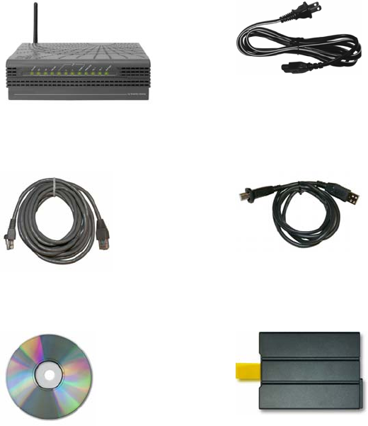
What's In the Carton?
When you receive your wireless home gateway, you should check the equipment
and accessories to verify that each item is in the carton and that each item is
undamaged. The carton contains the following items:
One DPC2434 Wireless Home
Gateway
One AC power cord
One Ethernet cable
(CAT5/RJ-45)
One USB cable
One CD-ROM containing the
user's guide and the USB drivers Lithium Ion cartridge battery
(Optional)
If any of these items are missing or damaged, please contact your service provider
for assistance.
Notes:
You will need an optional cable signal splitter and additional standard RF
coaxial cables if you want to connect a VCR, a Digital Home Communications
Terminal (DHCT) or a set-top converter, or a TV to the same cable connection as
your wireless home gateway.
Cables and other equipment needed for telephone service must be purchased
separately. Contact your service provider to inquire about the equipment and
cables you need for telephone service.
4011350 Rev A 13
Front Panel Description
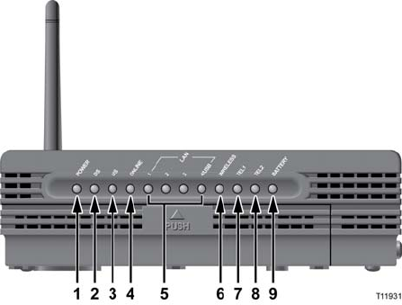
Front Panel Description
The front panel of your wireless home gateway provides LED status indicators that
indicate how well and at what state your wireless home gateway is operating. See
Front Panel LED Status Indicator Functions (on page 130), for more information on
front panel LED status indicator functions.
1 POWER—Illuminates solid green to indicate that AC power is being
applied to the wireless home gateway. AC power must be available to
recharge the batteries
2DS—Blinks to indicate that the wireless home gateway is receiving data
from the cable network
3US—Blinks to indicate that the wireless home gateway is sending data to
the cable network
4 ONLINE—Illuminates solid green when the wireless home gateway is
registered on the network and fully operational
5 LAN1 - LAN4/USB—Illuminates solid green to indicate that an
Ethernet/USB carrier is present and blinks to indicate that Ethernet/USB
data is being transferred between the PC and the wireless home gateway
6 WIRELESS—Illuminates solid green when the wireless access point is
enabled and operational and blinks to indicate that wireless data is being
transferred between the PC and the wireless home gateway. The LED is off
when the wireless access point is disabled by the user
7 TEL1—Illuminates solid green when telephony service is enabled. Blinks
when line 1 is in use
14 4011350 Rev A
Front Panel Description
8 TEL2—Illuminates solid green when telephony service is enabled. Blinks
when line 2 is in use
9 BATTERY—Illuminates solid green to indicate that the battery is charged.
Blinks to indicate that the battery charge is low. Off when operating from
battery power or when the battery charge is depleted or the battery is
defective
Notes:
After the wireless home gateway is successfully registered on the
network, the POWER (LED 1) and ONLINE (LED 4) LEDs illuminate
continuously to indicate that the cable modem is active and fully
operational.
LEDs may behave differently when the wireless home gateway is
running on battery power (without AC power). Most LEDs are
disabled if the unit is operating on battery power. In this mode, the
POWER LED blinks to indicate that the unit is operating under battery
power but AC power has failed.
Note: The wireless home gateway is shut off when operating on battery
power and only the telephone service is active.
4011350 Rev A 15
Back Panel Description
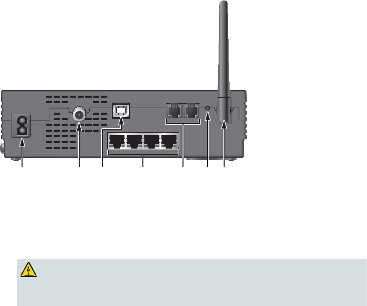
Back Panel Description
The following illustration shows the description and function of the back panel
components on the DPC2434.
CABLE
CABLE
CABLE USB
USB
USB
TELEPHONE
TELEPHONE
TELEPHONE
1
1
12
2
2RESET
RESET
RESET
1 2 3 7654 T11930
Important! Do not connect your PC to both the Ethernet and USB ports at the same
time. Your modem will not function properly if both the Ethernet and USB ports are
connected to your PC at the same time.
1 POWER—Connects the wireless home gateway to the AC power plug
that is provided with your wireless home gateway
CAUTION:
Avoid damage to your equipment. Only use the AC power cord that is
provided with your cable modem.
2 CABLE—F-Connector connects to an active cable signal from your cable
service provider
3 USB—12 Mbps USB port connects to the USB port on your PC
4 ETHERNET—Four RJ-45 Ethernet ports connect to the Ethernet port on
your PC or your home network
5 TELEPHONE 1 and 2—RJ-11 telephone ports connect to home telephone
wiring to conventional telephones or fax machines

16 4011350 Rev A
Back Panel Description
6 RESET—Activating this switch resets the EMTA. Pressing this switch for
more than ten seconds resets the device to factory default values and
resets the EMTA
CAUTION:
The Reboot EMTA button is for maintenance purposes only. Do not
use unless instructed to do so by your cable or telephone service
provider. Doing so may cause you to lose any cable modem settings
you have selected.
7 ANTENNA—Provides a communication connection for the built-in
wireless access point (WAP) to allow wireless devices to communicate
with the cable modem
4011350 Rev A 17
Where Is the Best Location for My Wireless Home Gatewa
y
?
Where Is the Best Location for My Wireless Home
Gateway?
The ideal location for your wireless home gateway is where it has access to outlets
and other devices. Think about the layout of your home or office, and consult with
your service provider to select the best location for your wireless home gateway.
Read this user's guide thoroughly before you decide where to place your wireless
home gateway.
Consider these recommendations:
Position your PC and wireless home gateway so that they are located near an AC
power outlet.
Position your PC and wireless home gateway so that they are located near an
existing cable input connection to eliminate the need for an additional cable
outlet. There should be plenty of room to guide the cables away from the modem
and the PC without straining or crimping them.
Airflow around the wireless home gateway should not be restricted.
Choose a location that protects the wireless home gateway from accidental
disturbance or harm.
18 4011350 Rev A
What Are the System Requirements for Internet Service?
What Are the System Requirements for Internet Service?
To ensure that your wireless home gateway operates efficiently for high-speed
Internet service, verify that all of the Internet devices on your system meet or exceed
the following minimum hardware and software requirements.
Note: You will also need an active cable input line and an Internet connection.
Minimum System Requirements for a PC
A PC with a Pentium MMX 133 processor or greater
32 MB of RAM
Web browsing software
CD-ROM drive
Minimum System Requirements for Macintosh
MAC OS 7.5
32 MB of RAM
System Requirements for an Ethernet Connection
A PC with Microsoft Windows 95 operating system (or later) with TCP/IP
protocol installed, or an Apple Macintosh computer with TCP/IP protocol
installed
An active 10/100BaseT Ethernet network interface card (NIC) installed
System Requirements for a USB Connection
A PC with Microsoft Windows 98SE, ME, 2000, or XP operating system
A master USB port installed in your PC or your Apple Macintosh computer

4011350 Rev A 19
How Do I Set Up My High-Speed Internet Access Account?
How Do I Set Up My High-Speed Internet Access Account?
Before you can use your wireless home gateway, you need to have a high-speed
Internet access account. If you do not have a high-speed Internet access account, you
need to set up an account with your local service provider. Choose one of the two
options in this section.
I Do Not Have a High-Speed Internet Access Account
If you do not have a high-speed Internet access account, your service provider will
set up your account and become your Internet Service Provider (ISP). Internet access
enables you to send and receive e-mail, access the World Wide Web, and receive
other Internet services.
You will need to give your service provider the following information:
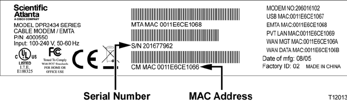
The serial number of the modem
The Media Access Control (MAC) address of the modem
These numbers appear on a bar code label located on the wireless home gateway.
The serial number consists of a series of alphanumeric characters preceded by S/N.
The MAC address consists of a series of alphanumeric characters preceded by CM
MAC. The following illustration shows a sample bar code label.
Write down these numbers in the space provided here.
Serial Number _______________________
MAC Address ________________________
I Already Have an Existing High-Speed Internet Access Account
If you have an existing high-speed Internet access account, you must give your
service provider the serial number and the MAC address of the wireless home
gateway. Refer to the serial number and MAC address information listed previously
in this section.
Note: You may not be able to continue to use your existing e-mail account with your
wireless home gateway. Contact your service provider for more information.
20 4011350 Rev A
How Do I Connect My Devices to Use the Internet?
How Do I Connect My Devices to Use the Internet?
You can use your wireless home gateway to access the Internet, and you can share
that Internet connection with other Internet devices in your home or office. Sharing
one connection among many devices is called networking.
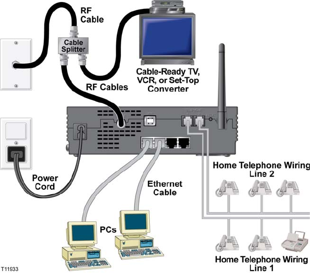
Connecting and Installing Internet Devices
You must connect and install your wireless home gateway to access the Internet.
Professional installation may be available. Contact your local cable service provider
for further assistance.
To connect devices
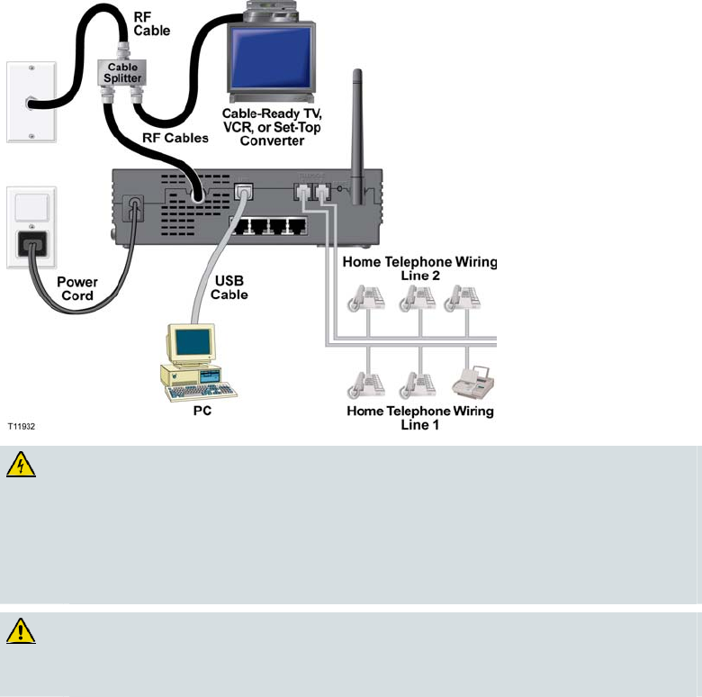
The following diagram illustrates one of the various networking options that are
available to you.

4011350 Rev A 21
How Do I Connect My Devices to Use the Internet?
Connecting the Modem for High-Speed Data Service
WARNING:
To avoid personal injury or damage to your equipment, follow these steps in
the exact order shown.
1Power off your PC and unplug it from the power source.
2Connect your PC to either the ETHERNET port or the USB port using the
appropriate data cable. Do not connect your PC to both the Ethernet and USB
ports at the same time. You can connect two separate PCs to the wireless home
gateway at the same time by connecting one PC to the Ethernet port and one PC
to the USB port.
3Connect the active RF coaxial cable to the CABLE connector. Use an optional
cable signal splitter to add a TV, a DHCT or set-top converter, or a VCR.
4Insert the AC power cord into the POWER connector on the back of the wireless
home gateway, and then plug the cord into an AC power source.
5Plug in and power on your networked devices including your PC. The wireless
home gateway will then begin an automatic search to locate and sign on to the
broadband data network. This process may take up to 5 minutes. The modem
will be ready for use when the ONLINE LED status indicator on the front panel
stops blinking and illuminates continuously.
6The next step in setting up your wireless home gateway is to configure your
Internet devices for Internet access. Choose one of the following options:
If you want to use Ethernet connections, you must configure the TCP/IP
protocol. To configure the TCP/IP protocol, go to How Do I Configure
TCP/IP Protocol? (on page 22).
If you want to use USB connections, you must install the USB drivers. To
install the USB Drivers for USB, go to How Do I Install USB Drivers?
(on page 25).
22 4011350 Rev A
How Do I Configure TCP/IP Protocol?
How Do I Configure TCP/IP Protocol?
To configure TCP/IP protocol, you need to have an Ethernet Network Interface Card
(NIC) with TCP/IP communications protocol installed on your system. TCP/IP is a
communications protocol used to access the Internet. This section contains
instructions for configuring TCP/IP on your Internet devices to operate with the
wireless home gateway in Microsoft Windows or Macintosh environments.
Configuring TCP/IP on Your Internet Devices
TCP/IP protocol in a Microsoft Windows environment is different for each
operating system. Follow the appropriate instructions in this section for your
operating system.
Configuring TCP/IP on Windows 95, 98, 98SE, or ME Systems
1Click Start, select Settings, and choose Control Panel.
2Double-click the Network icon in the Control Panel window.
3Read the list of installed network components under the Configuration tab to
verify that your PC contains the TCP/IP protocol/Ethernet adapter.
4Is TCP/IP protocol listed in the installed network components list?
If yes, go to step 7.
If no, click Add, click Protocol, click Add, and then go to step 5.
5Click Microsoft in the Manufacturers list.
6Click TCP/IP in the Network Protocols list, and then click OK.
7Click the TCP/IP Ethernet Adapter protocol, and then choose Properties.
8Click the IP Address tab, and then select Obtain an IP address automatically.
9Click the Gateway tab and verify that these fields are empty. If they are not
empty, highlight and delete all information from the fields.
10 Click the DNS Configuration tab, and then select Disable DNS.
11 Click OK.
12 Click OK when the system finishes copying the files, and then close all
networking windows.
13 Click YES to restart your computer when the System Settings Change dialog box
opens. The computer restarts. The TCP/IP protocol is now configured on your
PC, and your Ethernet devices are ready for use.
14 Try to access the Internet. If you cannot access the Internet, go to Having
Difficulty? (on page 126). If you still cannot access the Internet, contact your
service provider for further assistance.
4011350 Rev A 23
How Do I Configure TCP/IP Protocol?
Configuring TCP/IP on Windows 2000 Systems
1Click Start, select Settings, and choose Network and Dial-up Connections.
2Double-click the Local Area Connection icon in the Network and Dial-up
Connections window.
3Click Properties in the Local Area Connection Status window.
4Click Internet Protocol (TCP/IP) in the Local Area Connection Properties
window, and then click Properties.
5Select both Obtain an IP address automatically and Obtain DNS server address
automatically in the Internet Protocol (TCP/IP) Properties window, and then
click OK.
6Click Yes to restart your computer when the Local Network window opens. The
computer restarts. The TCP/IP protocol is now configured on your PC, and your
Ethernet devices are ready for use.
7Try to access the Internet. If you cannot access the Internet, go to Having
Difficulty? (on page 126). If you still cannot access the Internet, contact your
service provider for further assistance.
Configuring TCP/IP on Windows XP Systems
1Click Start, and depending on your Start menu setup, choose one of the
following options:
If you are using the Windows XP Default Start Menu, select Connect to,
choose Show all connections, and then go to step 2.
If you are using the Windows XP Classic Start Menu, select Settings, choose
Network Connections, click Local Area Connection, and then go to step 3.
2Double-click the Local Area Connection icon in the LAN or High-Speed Internet
section of the Network Connections window.
3Click Properties in the Local Area Connection Status window.
4Click Internet Protocol (TCP/IP), and then click Properties in the Local Area
Connection Properties window.
5Select both Obtain an IP address automatically and Obtain DNS server address
automatically in the Internet Protocol (TCP/IP) Properties window, and then
click OK.
6Click Yes to restart your computer when the Local Network window opens. The
computer restarts. The TCP/IP protocol is now configured on your PC, and your
Ethernet devices are ready for use.
7Try to access the Internet. If you cannot access the Internet, go to Having
Difficulty? (on page 126). If you still cannot access the Internet, contact your
service provider for further assistance.
24 4011350 Rev A
How Do I Configure TCP/IP Protocol?
Configuring TCP/IP on Macintosh Systems
1Click the Apple icon in the upper-left corner of the Finder. Scroll down to
Control Panels, and then click TCP/IP.
2Click Edit on the Finder at the top of the screen. Scroll down to the bottom of the
menu, and then click User Mode.
3Click Advanced in the User Mode window, and then click OK.
4Click the Up/Down selector arrows located to the right of the Connect Via
section of the TCP/IP window, and then click Using DHCP Server.
5Click Options in the TCP/IP window, and then click Active in the TCP/IP
Options window.
Note: Make sure that the Load only when needed option is unchecked.
6Verify that the Use 802.3 option located in the upper-right corner of the TCP/IP
window is unchecked. If there is a check mark in the option, uncheck the option,
and then click Info in the lower-left corner.
7Is there a Hardware Address listed in this window?
If yes, click OK. To close the TCP/IP Control Panel window, click File, and
then scroll down to click Close. You have completed this procedure.
If no, you must power off your Macintosh.
8With the power off, simultaneously press and hold down the Command
(Apple),Option,P, and R keys on your keyboard. Keeping those keys pressed
down, power on your Macintosh but do not release these keys until you hear the
Apple chime at least three times, then release the keys and let the computer
restart.
9When your computer fully reboots, repeat steps 1 through 7 to verify that all
TCP/IP settings are correct. If your computer still does not have a Hardware
Address, contact your authorized Apple dealer or Apple technical support center
for further assistance.
4011350 Rev A 25
How Do I Install USB Drivers?
How Do I Install USB Drivers?
To install USB drivers, your PC must be equipped with a USB network interface and
a Microsoft Windows 98SE, ME, 2000, or XP operating system. This section contains
instructions for installing the USB drivers for the wireless home gateway.
Note: If you are not using the USB interface, skip this section.
Installing USB Drivers
The USB driver installation procedures are different for each operating system.
Follow the appropriate instructions in this section for your operating system.
Installing USB Drivers on Windows 98SE and Windows ME Systems
1Insert the USB Cable Modem Driver Installation Disk into the CD-ROM drive
of your PC.
2Wait until the POWER and ONLINE LED status indicators on the front panel of
the wireless home gateway illuminate solid green. The Add New Hardware
Wizard window opens.
3Click Next in the Add New Hardware Wizard window.
4Select Search for the best driver for your device (Recommended) in the Add
New Hardware Wizard window, and then click Next.
5Select CD-ROM drive in the Add New Hardware Wizard window, and then
click Next.
6Select The updated driver (Recommended) in the Add New Hardware Wizard
window, and then click Next.
7Click Next in the Add New Hardware Wizard window. The Copying Files
window opens. After 10 to 20 seconds have passed, the Add New Hardware
Wizard window reopens.
8Click Finish. The USB driver installation is complete.
Installing USB Drivers on Windows 2000 Systems
1Insert the USB Cable Modem Driver Installation Disk into the CD-ROM drive
of your PC.
2Wait until the POWER and ONLINE LED status indicators on the front panel of
the wireless home gateway illuminate solid green.
3Click Next in the Found New Hardware Wizard window.
4Select Search for a suitable driver for my device (recommended) in the Found
New Hardware Wizard window, and then click Next.
5Select CD-ROM drives in the Found New Hardware Wizard window, and then
click Next.
26 4011350 Rev A
How Do I Install USB Drivers?
6Click Next in the Found New Hardware Wizard window. The system searches
for the driver file for your hardware device.
7After the system finds the USB driver, the Digital Signature Not Found window
opens and displays a confirmation message to continue the installation.
8Click Yes to continue the installation. The Found New Hardware Wizard
window reopens with a message that the installation is complete.
9Click Finish to close the Found New Hardware Wizard window. The USB
drivers are installed on your PC, and your USB devices are ready for use.
10 Try to access the Internet. If you cannot access the Internet, go to Having
Difficulty? (on page 126). If you still cannot access the Internet, contact your
service provider for further assistance.
Installing USB Drivers on Windows XP Systems
1Insert the USB Cable Modem Driver Installation Disk into the CD-ROM drive
of your PC.
2Wait until the POWER and ONLINE LED status indicators on the front panel of
the wireless home gateway illuminate solid green.
3Select Install from a list or specific location (Advanced) in the Found New
Hardware Wizard window, and then click Next.
4Select Search removable media (floppy, CD-ROM) in the Found New
Hardware Wizard window, and then click Next.
5Click Continue Anyway in the Hardware Installation window to continue the
installation. The Found New Hardware Wizard window reopens with a message
that the installation has finished.
6Click Finish to close the Found New Hardware Wizard window. The USB
drivers are installed on your PC, and your USB devices are ready for use.
7Try to access the Internet. If you cannot access the Internet, go to Having
Difficulty? (on page 126). If you still cannot access the Internet, contact your
service provider for further assistance.
4011350 Rev A 27
What Are the Requirements for Ethernet Network Devices?
What Are the Requirements for Ethernet Network Devices?
How Many Ethernet Network Devices Can I Connect?
The Scientific Atlanta wireless home gateway can support several Ethernet network
devices using external Ethernet hubs that must be purchased separately.
The theoretical maximum number of Ethernet network devices supported is by the
wireless home gateway is 63. However, under normal circumstances, the number of
devices connected should be a much lower number.
Contact your service provider for more information on the maximum number of
Ethernet network devices to connect to your wireless home gateway to maintain
optimal network performance.
What Are the Wiring Requirements for Ethernet Networking?
A number of factors can impact the practical limit of the network. Although the
wireless home gateway is designed to support several Ethernet network devices, it is
important to view the characteristics of the entire network and not just each
individual node.
The theoretical distance between two 10/100BaseT CAT-5 Ethernet hubs is 382 feet
(100 meters). Contact your service provider or consult the documentation for your
Ethernet network devices for more information.
Note: Scientific Atlanta recommends that you use CAT-5 Ethernet cables.
Do I Need to Configure the TCP/IP Protocol on My Computer?
For you to use Ethernet network devices on your network, you must have the
TCP/IP protocol properly configured on your PC. Refer to How Do I Configure
TCP/IP Protocol? (on page 22), for detailed information on configuring the TCP/IP
protocol.
28 4011350 Rev A
How Do I Select and Place Ethernet Network Devices?
How Do I Select and Place Ethernet Network Devices?
You can use a large variety of Ethernet network devices with your wireless home
gateway. These include NIC cards, hubs, bridges, etc. Contact your service provider
or consult the documentation for your Ethernet network devices for more
information on configuring Ethernet network devices.
Where Is the Best Location for My Ethernet Network Devices?
You should work with your service provider to choose the best location for your
Ethernet network devices. Consider these recommendations:
Location of two-way cable outlets
Distance of the Ethernet network devices from the wireless home gateway
Location of computers and other equipment from AC power outlets
Ease of running Ethernet cable to the Ethernet network devices
Now that you have selected a location for your Ethernet network devices, the next
step is to place and connect your Ethernet network devices. Go to How Do I Connect
Ethernet Network Devices? (on page 29).
4011350 Rev A 29
How Do I Connect Ethernet Network Devices?
How Do I Connect Ethernet Network Devices?
Connecting Ethernet Devices
You must connect your Ethernet devices for use with the wireless home gateway.
Professional installation may be available. Contact your local service provider for
further assistance.
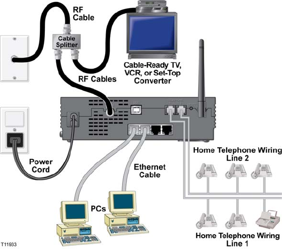
The following diagram illustrates one of the various Ethernet network connection
options that are available to you.
WARNING:
Hazardous electrical voltages can be present on any connected wiring.
Ethernet wiring and connections must be properly insulated to prevent
electrical shock. Disconnect power from the wireless home gateway before
attempting to connect to any device.
To avoid personal injury, follow these steps in the exact order shown.
CAUTION:
To prevent possible damage to the equipment, disconnect any other service
before connecting your wireless home gateway to other devices.
Read the warnings and caution on this page. Then, follow the subsequent
installation procedures to ensure proper wireless home gateway operation when
connecting Ethernet network devices.
30 4011350 Rev A
How Do I Connect Ethernet Network Devices?
1Select locations for Ethernet network devices. For more information, see How Do
I Select and Place Ethernet Network Devices? (on page 28).
2Connect the Ethernet port on the wireless home gateway to your PC.
3Connect additional Ethernet network devices by connecting an Ethernet hub or
router to the wireless home gateway.
4Connect the active RF coaxial cable to the CABLE connector on the back of the
wireless home gateway. Use an optional cable signal splitter to add a TV, a
DHCT or set-top converter, or a VCR.
5After all connections are complete, insert the AC power cord into the POWER
connector on the back of the wireless home gateway, and then plug the cord into
an AC power source.
6The wireless home gateway begins an automatic search to locate and sign on to
the network. In some unusual circumstances, this process may take up to 5
minutes. The wireless home gateway is ready for use when the ONLINE LED
status indicator on the front panel stops blinking and illuminates continuously.
7Verify that all Ethernet network devices are working properly.
Note: You will not be able to check the front panel LED status indicator on the
wireless home gateway until after one or more Ethernet network devices are
connected to the wireless home gateway.
4011350 Rev A 31
What Are the Requirements for USB Network Devices?
What Are the Requirements for USB Network Devices?
How Many USB Devices Can I Connect?
Contact your service provider for more information on the maximum number of
USB network devices to connect to the wireless home gateway to maintain optimal
network performance.
What Are the Wiring Requirements?
Several factors can impact the practical limit of the network. Contact your service
provider or consult the documentation for your USB network device for more
information.
Do I Need to Install USB Drivers on My Computer?
To use USB network devices, you must have the correct USB drivers installed on
your PC. Refer to How Do I Install USB Drivers? (on page 25), for information on
installing USB drivers.
32 4011350 Rev A
How Do I Select and Place USB Network Devices?
How Do I Select and Place USB Network Devices?
You can use a large variety of USB network devices with your wireless home
gateway. These include desktop computers, laptop computers, devices with USB
ports, and USB adapters.
Contact your service provider or consult the documentation for your USB network
devices for more information on selecting USB network devices.
Where Is the Best Location for My USB Network Devices?
You should work with your service provider to choose the best location for your
USB network devices. Consider these recommendations:
Location of two-way coaxial cable outlets
Distance of the USB network devices from the wireless home gateway
Location of computers and other equipment from AC power outlets
Ease of running USB cable to the USB network devices
Now that you have selected a location for your USB network devices, the next step is
to place and connect your USB network devices. Go to How Do I Connect USB
Network Devices? (on page 33).
4011350 Rev A 33
How Do I Connect USB Network Devices?
How Do I Connect USB Network Devices?
Connecting USB Devices
You must connect your USB devices for use with your wireless home gateway.
Professional installation may be available. Contact your local service provider for
further assistance.
The following diagram illustrates one of the various USB network connection
options that are available to you.
WARNING:
Hazardous electrical voltages can be present on any connected wiring. USB
wiring and connections must be properly insulated to prevent electrical shock.
Disconnect power from the wireless home gateway before attempting to
connect to any device.
To avoid personal injury, follow these steps in the exact order shown.
CAUTION:
To prevent possible damage to the equipment, disconnect any other service
before connecting your wireless home gateway to other devices.
Read the warnings and caution on this page. Then, follow the subsequent
installation procedures to ensure proper wireless home gateway operation when
connecting USB network devices.
34 4011350 Rev A
How Do I Connect USB Network Devices?
Note: Verify that you have installed the USB drivers on your PC before continuing
with these instructions. See How Do I Install USB Drivers? (on page 25), for more
information on installing the USB drivers.
1Select locations for USB network devices. For more information, see How Do I
Select and Place USB Network Devices? (on page 31).
2Connect the USB port on the wireless home gateway to your PC.
3Connect one or more USB network device to the wireless home gateway.
4Connect the active RF coaxial cable to the CABLE connector on the back of the
wireless home gateway. Use an optional cable signal splitter to add a TV, a
DHCT or set-top converter, or a VCR.
5After all connections are complete, insert the AC power cord into the POWER
connector on the back of the wireless home gateway, and then plug the cord into
an AC power source.
6The wireless home gateway begins an automatic search to locate and sign on to
the network. In some unusual circumstances, this process may take up to 5
minutes. The wireless home gateway is ready for use when the ONLINE LED
status indicator on the front panel stops blinking and illuminates continuously.
7Verify that all USB network devices are working properly.
Note: You will not be able to check the front panel LED status indicator on the
wireless home gateway until after one or more Ethernet network devices are
connected to the wireless home gateway.
4011350 Rev A 35
How Do I Troubleshoot My Internet Service Installation?
How Do I Troubleshoot My Internet Service Installation?
I cannot connect to the Internet
Verify that the plug to your wireless home gateway AC power is properly
inserted into an electrical outlet.
Verify that your wireless home gateway AC power cord is not plugged into an
electrical outlet that is controlled by a wall switch. If a wall switch controls the
electrical outlet, make sure the switch is in the ON position.
Verify that the POWER and CABLE indicator lights on the front panel of your
wireless home gateway are illuminated.
Verify that the indicator lights on your router or other network connection
equipment are illuminated
Verify that all cables are properly connected, and that you are using the correct
cables.
Verify that your cable service is active and that it supports two-way service.
Verify that TCP/IP is properly installed and configured on all devices if you are
using the Ethernet connections.
Verify that you have followed the procedure in How Do I Install USB Drivers?
(on page 25), if you are using the USB connection.
Verify that you have called your service provider and given them the serial
number and MAC address of your wireless home gateway.
If you are using a cable signal splitter so that you can connect the cable signal to
other devices, remove the splitter and reconnect the cable so that the wireless
home gateway is connected directly to the main cable input. If the wireless home
gateway now functions properly, the cable signal splitter may be defective and
may need to be replaced.
My wireless home gateway does not register an Ethernet connection
Even new devices do not always have Ethernet capabilities. Verify that your device
has an Ethernet card and that the Ethernet driver software is properly installed. If
you purchase and install an Ethernet card, follow the installation instructions very
carefully.
36 4011350 Rev A
How Do I Troubleshoot My Internet Service Installation?
My wireless home gateway does not register a cable connection
The wireless home gateway works with a standard, 75-ohm, RF coaxial cable. If
you are using a different cable, your wireless home gateway will not function
properly. Contact your service provider to determine if you are using the correct
cable.
You may need to renew the IP address on your PC. Refer to How Do I Renew the
IP Address on My PC? (on page 37), for instructions on how to renew the IP
address for your particular operating system.
Your USB interface may be malfunctioning. Refer to the troubleshooting
information in your USB documentation.
4011350 Rev A 37
How Do I Troubleshoot My Internet Service Installation?
How Do I Renew the IP Address on My PC?
If your PC cannot access the Internet after the wireless home gateway is online, it is
possible that your PC did not renew its IP address. Follow the appropriate
instructions in this section for your operating system to renew the IP address on
your PC.
Renewing the IP address on Windows 95, 98, 98SE, and ME Systems
1Click Start, and then click Run to open the Run window.
2Type winipcfg in the Open field, and click OK to execute the winipcfg
command. The IP Configuration window opens.
3Click the down arrow to the right of the top field, and select the Ethernet adapter
that is installed on your PC. The IP Configuration window displays the Ethernet
adapter information.
4Click Release, and then click Renew. The IP Configuration window displays a
new IP address.
5Click OK to close the IP Configuration window, you have completed this
procedure.
Note: If you cannot access the Internet, contact your service provider for further
assistance.
Renewing the IP Address on Windows NT, 2000, or XP Systems
1Click Start, and then click Run. The Run window opens.
2Type cmd in the Open field and click OK. A window with a command prompt
opens.
3Type ipconfig/release at the C:/ prompt and press Enter. The system releases
the IP address.
4Type ipconfig/renew at the C:/ prompt and press Enter. The system displays a
new IP address.
5Click the X in the upper-right corner of the window to close the Command
Prompt window. You have completed this procedure.
Note: If you cannot access the Internet, contact your service provider for further
assistance.
38 4011350 Rev A
What Are the Requirements for Wireless Network Devices?
What Are the Requirements for Wireless Network Devices?
How Many Wireless Devices Can I Connect?
The DPC2434 serves as a wireless access point (WAP). The WAP on the DPC2434
provides wireless network service to multiple wireless network devices. Contact
your cable service provider for more information on the maximum number of
wireless network devices to connect to the DPC2434 in order to maintain optimal
network performance.
What are the Requirements for Wireless Networking?
It is important to view the characteristics of the entire network and not just each
individual node. The theoretical distance between wireless network devices is 100
feet inside of a building, and 300 feet outdoors.
A number of factors can impact the practical limit of the network. Contact your cable
service provider or consult the documentation for your wireless network devices for
more information.
4011350 Rev A 39
How Do I Select and Place Wireless Network Devices?
How Do I Select and Place Wireless Network Devices?
You can use a large variety of wireless network devices with your wireless home
gateway. These include computers, PDAs, etc. On the wireless network, all devices
impact the characteristics of the network, because each device transmits a wireless
signal. Contact your cable service provider or consult the documentation for your
wireless network device for more information on selecting the appropriate wireless
network devices for your home or office network.
Where Is the Best Location for My Wireless Network Devices?
You should work with your cable service provider to choose the best location for
your wireless network devices. Consider these recommendations:
Distance from the wireless home gateway to the wireless network devices.
Do not place the wireless home gateway near metallic surfaces that may block
the wireless communications path. Wireless communication is “line-of-sight”
through non-metallic walls. However, the more structures (walls) the signal
must pass through, the weaker the received signal.
Do not place wireless network devices near a microwave oven. When operating,
microwave ovens can interfere with wireless transmissions.
Do not place your wireless network devices near 2.4 GHz wireless telephones
because these telephones may also cause interference with your wireless
network.
Now that you have selected a location for your wireless network devices, the next
step is to place and install your wireless network devices. Go to How Do I Install
Wireless Network Devices? (on page 40).
40 4011350 Rev A
How Do I Install Wireless Network Devices?
How Do I Install Wireless Network Devices?
Installing Wireless Network Devices
You must install wireless network devices for use with your wireless home gateway.
Professional installation may be available. Contact your local cable service provider
for further assistance.
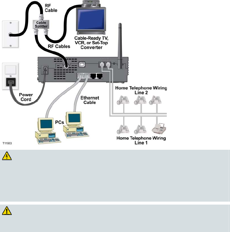
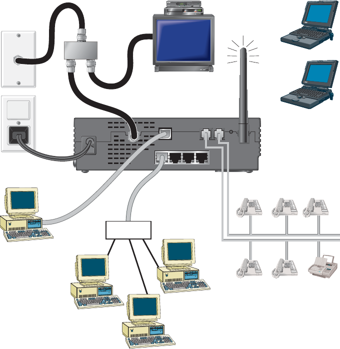
The following diagram illustrates one of the various wireless network connection
options that are available to you.
CABLE
CABLE
CABLE USB
USB
USB
TELEPHONE
TELEPHONE
TELEPHONE
1
1
12
2
2RESET
RESET
RESET
Power
Cord
Cable-Ready TV,
VCR, or Set-Top
Converter
PC
USB
Cable
RF Cables
RF
Cable
Cable
Splitter
T11954
BYPASS
VOL– VOL+
CH+
CH–
MENU GUIDE INFO A/B POWER
Ethernet
Hub
PC
PC
PC
Wireless
Laptops
Home Telephone Wiring
Line 1
Home Telephone Wiring
Line 2

4011350 Rev A 41
How Do I Install Wireless Network Devices?
To install wireless network devices
WARNING:
Hazardous electrical voltages can be present on any connected wiring.
Ethernet wiring and connections must be properly insulated to prevent
electrical shock. Disconnect power from the wireless home gateway before
attempting to connect to any device.
To avoid personal injury, follow these steps in the exact order shown.
CAUTION:
To prevent possible damage to the equipment, disconnect any other service
before connecting your wireless home gateway to other devices.
Read the warnings and caution on this page. Then, follow the subsequent
installation procedures to ensure proper wireless home gateway operation when
using wireless network devices.
Installing Wireless Network Devices
Follow these steps to install the wireless home gateway for accessing wireless
network devices.
1Select locations for wireless network devices. For more information, see How Do
I Select and Place Wireless Network Devices? (on page 39).
2Connect and install the wireless network device(s).
3Connect the active RF coaxial cable to the CABLE connector on the back of the
wireless home gateway. Use an optional cable signal splitter to add a TV, a
DHCT or set-top converter, or a VCR.
4After all connections are complete, insert the AC power cord into the POWER
connector on the back of the wireless home gateway, and then plug the power
cord into an AC power source. The wireless home gateway begins an automatic
search to locate and sign on to the network. In some unusual circumstances, this
process may take up to 5 minutes. The wireless home gateway is ready for use
when the ONLINE LED status indicator on the front panel stops blinking and
illuminates continuously.
Note: Some 2.4 GHz cordless telephones can interfere with wireless signals.
Unplug and disconnect any cordless phones until your wireless network is
operating properly.
5Verify that all wireless network devices are working properly.
42 4011350 Rev A
How Do I Use My Wireless Home Gateway for Telephone Service?
How Do I Use My Wireless Home Gateway for Telephone
Service?
Contacting Your Local Service Provider
You need to set up a telephone account with your local service provider to use your
wireless home gateway for telephone service. When you contact your service
provider, verify the following conditions:
Does the service to your home support two-way, DOCSIS-compatible wireless
home gateway access? If your service provider does not provide two-way
service, this modem will not be able to communicate with your service provider's
Internet access and telephone services.
Can you transfer your existing telephone numbers from another telephony
service provider to your current telephony service provider? In some areas, you
may be able to transfer your existing telephone numbers, or your cable telephony
service provider will assign a new telephone number for each current or
additional active telephone line. Discuss these options with your telephony
service provider.
You will need to give your service provider the following information:
The serial number of the modem
The Media Access Control (MAC) address of the modem
These numbers appear on a bar code label located on the wireless home gateway.
The serial number consists of a series of alphanumeric characters preceded by S/N.
The MAC address consists of a series of alphanumeric characters preceded by CM
MAC. The following illustration shows a sample bar code label.
Write down these numbers in the space provided here.
Serial Number _______________________
MAC Address ________________________
4011350 Rev A 43
Where Do I Place My Wireless Home Gateway for Telephone Service?
Where Do I Place My Wireless Home Gateway for Telephone
Service?
If you are planning to use your modem for telephone service, you should work with
your cable telephony provider to choose the best location for your modem.
Where Is the Best Location for My Modem?
When choosing a location for your modem, consider the following
recommendations:
Choose a location close to your computer if you will also use the wireless home
gateway for high-speed Internet service.
Choose a location that is near an existing RF coaxial connection to eliminate the
need for an additional RF coaxial outlet.
Choose a location for the wireless home gateway that is adjacent to your
telephone equipment if you are using only one or two pieces of telephone
equipment.
Note: If you are using the wireless home gateway to provide service to several
telephones, a professional installer can connect the wireless home gateway to your
existing home telephone wiring. To minimize changes to the home telephone wiring,
you may want to locate the wireless home gateway near an existing telephone outlet.
See How Do I Install the Modem for Telephone Service? (on page 45), for further
instructions.
Choose a location that is relatively protected from accidental disturbance or
harm, such as a closet, basement, or other protected area.
Choose a location so that there is plenty of room to guide the cables away from
the modem without straining or crimping them.
Airflow around the wireless home gateway should not be restricted.
Read this user's guide thoroughly before installing the wireless home gateway.
44 4011350 Rev A
What Are the Requirements for Telephone Service?
What Are the Requirements for Telephone Service?
This section provides hardware and software requirements for using your wireless
home gateway for telephone service.
Number of Telephone Devices
The RJ-11 telephone-style connectors on the wireless home gateway can each
provide telephone service to multiple telephones, fax machines, and analog
modems.
The maximum number of telephone devices connected to each RJ-11 port is limited
by the total Ringing Load of the telephone devices that are connected. Many
telephone devices are marked with a Ringer Equivalent Number (REN). Each
telephone port on the wireless home gateway can support up to a 5 REN load.
The sum of the REN load on all of the telephone devices attached to each port must
not exceed 5 REN.
Telephone Device Types
You can use telephone devices that are not labeled with a REN number, but the
maximum number of attached telephone devices cannot be accurately calculated.
With telephone devices that are not labeled, each device should be connected and
the ring signal should be tested before adding more devices. If too many telephone
devices are attached and the ring signal can no longer be heard, telephone devices
should be removed until the ring signal works properly.
Telephones, fax machines, and other telephone devices should use the center 2 pins
of the RJ-11 connectors to connect to the wireless home gateway telephone ports.
Some telephones use other pins on the RJ-11 connectors and require adapters in
order to work.
Dialing Requirements
All your telephones should be set to use DTMF dialing. Pulse dialing is typically not
enabled by your local provider.
Telephone Wiring Requirements
The wireless home gateway supports interior telephone wiring. The maximum
distance from the unit to the most distant telephone device must not exceed 1000 feet
(300 meters). Use 26-gauge twisted-pair, or larger, telephone wiring.
Important! Connection to an existing or a new permanently installed home
telephone-wiring network must be done by a qualified installer.

4011350 Rev A 45
How Do I Install the Modem for Telephone Service?
How Do I Install the Modem for Telephone Service?
The wireless home gateway can be used to provide telephone service for one or two
telephone lines. This section describes how to connect a single telephone, fax
machine, analog telephone modem, or other telephone device to each telephone port
on the wireless home gateway.
Important! Connecting the wireless home gateway permanently to the installed
home telephone wiring is not covered by this document.
Installing the Modem to Provide Telephone Service
Heed the following warnings, and then follow the subsequent installation
procedures to ensure proper wireless home gateway installation and configuration
for providing telephone service.
WARNING:
To avoid personal injury, follow the installation instructions in the exact
order shown.
Telephone connections to an installed home telephone wiring network
must be done by a qualified installer. The cable telephone service
provider may offer professional installation and connection to the home
telephone wiring network. A fee may be charged for this service.
Hazardous electrical voltages can exist on the telephone ports on the cable
modem and can be present on any connected wiring. Telephone wiring
and connections must be properly insulated to prevent electrical shock.
Disconnect power from the cable modem before attempting to connect to
any device.
To prevent possible damage to equipment, disconnect any other telephone
service before connecting your cable modem to the same wires.
Note: Professional installation may be available. Contact your service provider for
further assistance.
46 4011350 Rev A
How Do I Install the Modem for Telephone Service?
Installation Diagram
The following diagram illustrates one of the various connection options that are
available to you.
To install the wireless home gateway for telephone service
1Connect a telephone, fax machine, or analog modem to each of the appropriate
RJ-11 ports on the wireless home gateway.
Notes:
The wireless home gateway provides one line of telephone service on each of
the RJ-11 connectors.
Service must be set up and enabled by the telephone service provider.
The two center conductors (pins 3 and 4) on the RJ-11 connector provide
electrical connections to directly attached telephone devices or to a
permanently installed in-home telephone wiring network.
The telephone port labeled Line 1 also supports multi-line telephone devices.
Line 1 is supported on pins 3 and 4, and Line 2 is supported on pins 2 and 5.
The use of telephones that require electrical connections to other RJ-11 pins
requires an adapter.
2After all telephone connections are complete, insert the AC power cord into the
power connector on the back of the wireless home gateway, and then plug the
cord into an AC power source.
4011350 Rev A 47
How Do I Install the Modem for Telephone Service?
3Connect the active RF coaxial cable to the CABLE connector on the back of the
wireless home gateway. The wireless home gateway begins an automatic search
to locate and sign on to the network that provides the telephone service. This
process may take up to 5 minutes. The modem will be ready for use when the
ONLINE LED status indicator on the front panel stops blinking and illuminates
continuously
Note: Use an optional cable signal splitter to add a TV, a DHCT or set-top
converter, or a VCR.
4Test your telephone service by lifting the receiver of each attached telephone to
verify that the dial tone can be heard and that you can make and receive
telephone calls. This process may take several minutes.
Notes:
The TEL 1 and TEL 2 LED status indicators on the front panel of the wireless
home gateway illuminate when telephony service is enabled.
The TEL 1 or the TEL 2 LED status indicators on the front panel of the
wireless home gateway blink when the attached device is “off the hook.”

48 4011350 Rev A
How Do I Maintain the Batteries?
How Do I Maintain the Batteries?
Your modem includes up to two rechargeable Lithium-Ion batteries to provide
stand-by operation in the event of an AC power failure. You can replace one or both
of the batteries without the use of any tools.
WARNING:
There is danger of explosion if the battery is mishandled or incorrectly
replaced. Replace only with the same type of battery. Do not disassemble it or
attempt to recharge the battery outside the system. Do not crush, puncture,
dispose of in a fire, short external contacts, or expose to water or other liquids.
Dispose of the battery in accordance with local regulations and instructions
from your service provider.
Charging the Batteries
The batteries begin to charge automatically as soon as you attach the modem to the
AC electrical outlet. When you first plug in the modem, the POWER LED status
indicator illuminates.
Important! It may take as long as 24 hours for each battery to charge fully.
Using the Modem Without a Battery
If you want, you can use the modem without a battery. If you need to remove the
batteries, follow the procedures found in Removing and Replacing the Batteries
(on page 49), later in this section.
Important! If you choose to operate your modem without a battery, you risk losing
your telephone service during a power outage.
Replacing the Batteries
Under normal circumstances, the battery should last for several years. The
BATTERY LED status indicator turns off to indicate that the battery should be
replaced soon. Contact your service provider to obtain replacement batteries and for
disposal instructions.
Note: Follow the steps found in Removing and Replacing the Batteries (on page 49),
to remove and replace one or both of the batteries.
4011350 Rev A 49
How Do I Maintain the Batteries?
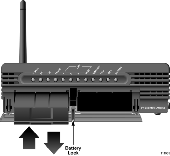
Location of Batteries
The following illustration shows the location of the batteries on the wireless home
gateway.
Removing and Replacing the Batteries
Follow these steps to remove and replace one or both of the batteries. You can
remove and replace the batteries without disconnecting the AC power source.
1Gently press the battery cover on the front of the modem to open the battery
cover and gain access to the battery compartment.
2Slide the battery lock upward (toward the front panel LEDs) to disengage the
battery lock.
3Grasp the plastic strip on the front of the battery and gently slide the battery
forward to remove it from the battery compartment.
4Insert a new battery into the battery compartment.
5Repeat steps 3 and 4 if you are replacing both batteries. Then, go to step 6.
6Close the battery compartment door. The battery lock will automatically engage.
Important! It may take as long as 24 hours for each battery to charge fully.
Note: Dispose of the battery in accordance with local regulations and
instructions from your service provider.
50 4011350 Rev A
How Do I Mount the Modem on a Wall? (Optional)
How Do I Mount the Modem on a Wall? (Optional)
You can mount the wireless home gateway on a wall using two wall anchors, two
screws, and the mounting slots located on the unit. The modem can be mounted
vertically or horizontally.
Before You Begin
Before you begin, choose an appropriate mounting place. The wall can be made of
cement, wood, or drywall. The mounting location should be free of obstructions on
all sides, and the cables should be able to easily reach the wireless home gateway
without strain. Leave sufficient clearance between the bottom of the wireless home
gateway and any flooring or shelving underneath to allow access to cabling. In
addition, leave enough slack in all cables so that the wireless home gateway can be
removed for any required maintenance without disconnecting the cables. Also,
verify that you have the following items:
Two wall anchors for #8 x 1 inch screws
Two #8 x1 inch pan head sheet metal screws
Drill with a 3/16-in. wood or masonry bit, as appropriate for the wall
composition
A copy of the wall-mounting illustrations shown on the following pages
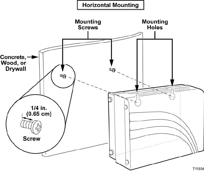
4011350 Rev A 51
How Do I Mount the Modem on a Wall?
(
Optional
)
Mount the modem as shown in the following illustration.
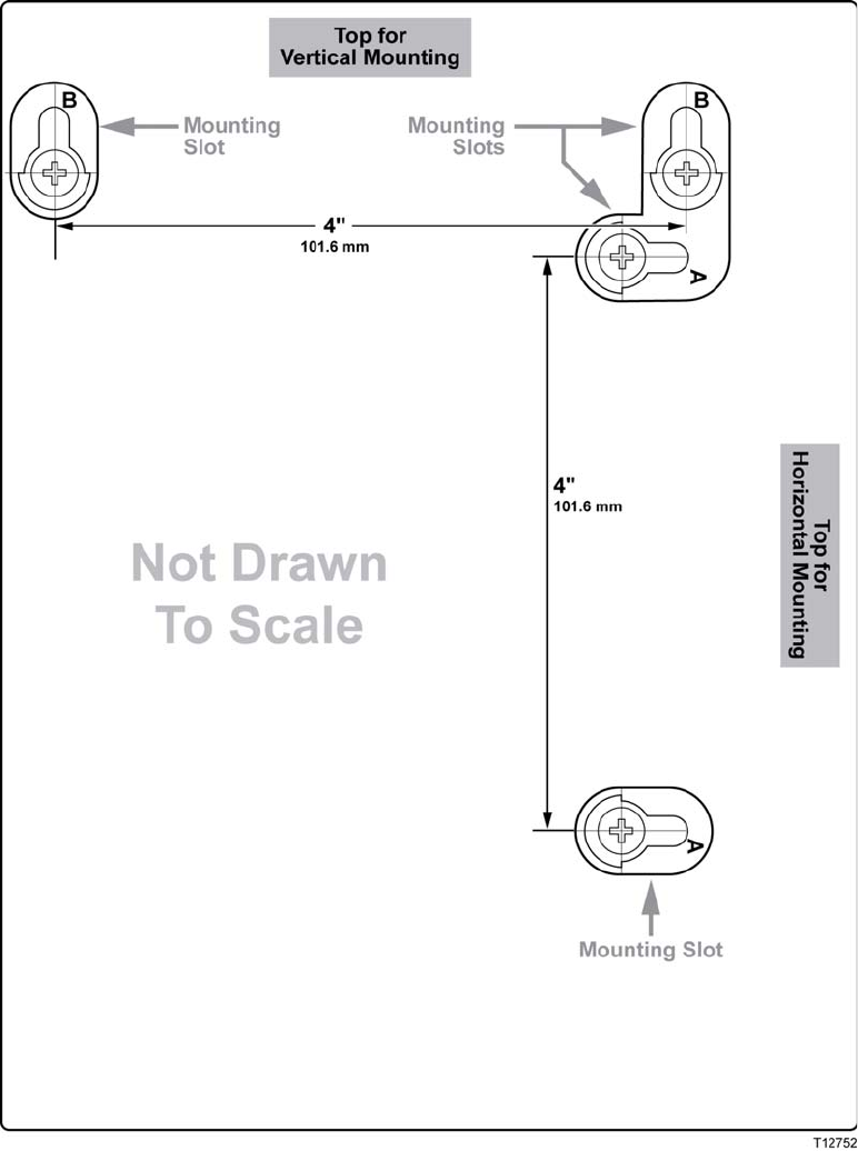
52 4011350 Rev A
How Do I Mount the Modem on a Wall? (Optional)
Location and Dimensions of the Wall-Mounting Slots
The following illustration shows the location and dimensions of the wall-mounting
slots on the bottom of the modem. Use the information on this page as a guide for
mounting your modem to the wall.
4011350 Rev A 53
How Do I Mount the Modem on a Wall?
(
Optional
)
Mounting the Wireless Home Gateway on a Wall
To mount the wireless home gateway on a wall
Complete these steps to mount the wireless home gateway on the wall.
1Using a drill with a 3/16-in. bit, drill two holes in the wall as follows:
To mount the wireless home gateway vertically, drill the holes at the same
height and 4 inches apart.
To mount the wireless home gateway horizontally, drill the holes at the same
height and 4 inches apart.
Note: The graphic on the preceding page illustrates the location of the mounting
holes on the back of the wireless home gateway.
2Are you mounting the wireless home gateway into a drywall or concrete surface
where a wooden stud is available?
If no, drive the anchor bolts into the wall, and install the mounting screws
into the anchor bolts leaving a gap of about 1/4-in. between the screw head
and the wall. Then, go to step 4.
If yes, go to step 3.
3Install the mounting screws into the wall leaving a gap of about 1/4-in. between
the screw head and the wall. Then, go to step 4.
4Verify that no cables or wires are connected to the wireless home gateway.
5Lift the wireless home gateway into position. Slip the large end of both mounting
slots (located in the back of the wireless home gateway) over the mounting
screws, then slide the wireless home gateway down until the narrow end of the
keyhole slot contacts the screw shaft.
Important! Verify that the mounting screws securely support the wireless home
gateway before you release the unit.
54 4011350 Rev A
How Do I Configure the Wireless Home Gateway?
How Do I Configure the Wireless Home Gateway?
To configure your wireless home gateway, you must first access the WebWizard
configuration pages. This section provides detailed instructions and procedures for
accessing the WebWizard pages and for configuring your wireless home gateway to
operate correctly. This section also presents examples and descriptions of each
WebWizard configuration page. Use the WebWizard pages to customize your
wireless home gateway to your needs rather than using the default settings.
Important! The WebWizard pages and the examples shown in this section are for
illustration purposes only. Your pages may differ from the pages shown in this
guide.
Note: If you are not familiar with the network configuration procedures detailed in
this section, contact your cable service provider before you attempt to change any of
the wireless home gateway default settings.
Accessing the Wireless Home Gateway
You must access the WebWizard in order to configure the wireless home gateway.
To gain access to the WebWizard, use the Web browser on the PC attached to the
gateway.
1Open the Web browser on your PC.
2Type the following IP address and then select Go:
http://192.168.0.1.
3The Web browser accesses the WebWizard and displays the default About Your
Modem page. This page displays information about your cable modem along
with a series of tabs for accessing other WebWizard configuration and operation
features.
Note: The About Your Modem page is accessible only when the modem is
offline. This page is used to provide helpful information during the installation
process or when troubleshooting network-related problems. Once the modem is
online, the About Your Modem page is hidden from view.
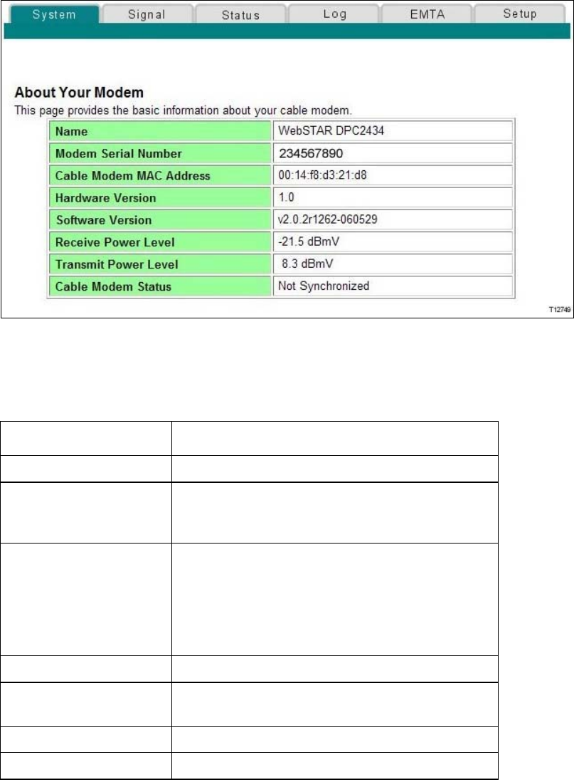
4011350 Rev A 55
How Do I Configure the Wireless Home Gatewa
y
?
About Your Modem Page Example
The following illustration is an example of the About Your Modem page.
About Your Modem Page Description
The following table provides a description of each field within the About Your
Modem page.
Field Name Description
Name The name of the wireless home gateway
Modem Serial Number A unique sequential series of alphanumeric
characters provided to every modem during
manufacturing
Cable Modem MAC
Address
A unique alphanumeric address for the cable
modem coaxial interface, which is used to connect
to the cable modem termination system (CMTS) at
the headend. A media access control (MAC)
address is a hardware address that uniquely
identifies each node of a network
Hardware Version Identifies the revision of the circuit board design
Software Version Identifies the software version placed into the
modem at the time of manufacturing
Receive Power Level The input level of the downstream CMTS carrier
Transmit Power Level Indicates the upstream power level

56 4011350 Rev A
How Do I Configure the Wireless Home Gateway?
Field Name Description
Cable Modem Status Lists one of the following possible current states of
the modem:
other
notReady
notSynchronized
phySynchronized
usParametersAcquired
rangingComplete
ipComplete
todEstablished
securityEstablished
psrsmTransferComplete
registrationComplete
operational
accessDenied
4011350 Rev A 57
How Do I Configure the Wireless Home Gatewa
y
?
Setting Configuration Options
Use the Setup page to access the various configuration options for the wireless home
gateway. Detailed descriptions of each configuration option follow later in this
guide.
Important! After you click the Setup tab, or whenever you access the WebWizard by
typing the 192.168.0.1 IP address into your Web Browser while the gateway is online,
an authentication window similar to the following window opens:
To access the Setup page, leave the user name blank and enter your password. Then
click OK to continue to the Setup page.
Important! If you have not set up a password, leave both the User Name and
Password field blank and click OK to continue to the Setup page.
Note: The gateway ships from the factory without a factory-assigned default
password. See Configuring Your Password Settings (on page 64) for assistance in
setting up your password.
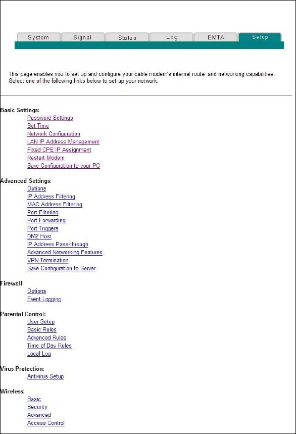
58 4011350 Rev A
How Do I Configure the Wireless Home Gateway?
Setup Page Example
The following illustration is an example of the Setup page.
Setup Page Section Headings
The Setup page is divided into the following section headings:
Basic Settings
Advanced Settings
Firewall
Parental Control

4011350 Rev A 59
How Do I Configure the Wireless Home Gatewa
y
?
Virus Protection
Wireless
In the Setup page, click the selections listed within these sections to access the
WebWizard page for that selection. A description of the selections available in each
section follows next.
Basic Settings
The following table provides a description of the pages available from within the
Basic Settings section of the Setup page.
Field Name Description
Password Settings Use this page to set or modify your password settings
Set Time Use this page to enable or disable time synchronization
by Network Time protocol
Network Configuration Use this page to enter or modify the basic settings for
your network
LAN IP Address
Management
Use this page to configure how Internet protocol (IP)
addresses are assigned and managed in your network
Fixed CPE IP Assignment Use this page to reserve IP addresses in the DHCP pool
that will be used as static IP addresses in your local
network.
Restart Modem Use this page to restart your wireless home gateway
Save Configuration to
your PC
Use this page to save your cable modem RG
configuration to your local PC and to restore the RG
configuration to your wireless home gateway, if
necessary

60 4011350 Rev A
How Do I Configure the Wireless Home Gateway?
Advanced Settings
The following table provides a description of the pages available from within the
Advanced Settings section of the Setup page.
Field Name Description
Options Use this page to enable or disable advanced features
on your network
IP Address Filtering Use this page to configure IP address filters. These
filters prevent designated IP addresses from accessing
the Internet
MAC Address
Filtering
Use this page to configure MAC address filters. These
filters prevent designated MAC addresses from
accessing the Internet
Port Filtering Use this page to configure transmission control
protocol (TCP) and user datagram protocol (UDP) port
filters. These filters prevent a range of TCP/UDP ports
from accessing the Internet
Port Forwarding Use this page to configure port forwarding for local IP
addresses. Port forwarding allows you to run a server
on the local area network (LAN) by specifying the
mapping of TCP/UPD ports to local PCs or to the IP
address of other devices. This is a static setting that
holds the ports open at all times
Port Triggers Use this page to configure TCP/UPD port triggers.
Port triggering is similar to port forwarding, but is a
dynamic function. In other words, the ports are not
held open, and the ports close if no outgoing data is
detected on the selected ports for a period of 10
minutes

4011350 Rev A 61
How Do I Configure the Wireless Home Gatewa
y
?
Field Name Description
DMZ Host
(Demilitarized Zone)
Use this page to configure an IP address that is visible
to the wide area network (WAN). DMZ hosting is
commonly referred to as “exposed host,” and allows
you to specify the “default” recipient of WAN traffic
that Network Address Translation (NAT) is unable to
translate to a known local PC.
A DMZ is used by a company that wants to host its
own Internet services without sacrificing unauthorized
access to its private network. DMZ allows one IP
address to be unprotected while others remain
protected. The DMZ is located between the Internet
and an internal network's line of defense that is a
combination of firewalls and bastion hosts.
Typically, the DMZ contains devices accessible to
Internet traffic, such as Web (HTTP) servers, FTP
servers, SMTP (e-mail) servers, and domain name
system (DNS) servers
IP Address Pass-
through
Allows the user with network administrator access to
designated MAC addresses of CPE devices in the
private LAN network to be assigned public IP
addresses instead of private IP addresses.
Note: This link is displayed when the user enters the
Network Administrator User Name and Password.
This link is not displayed during normal user access.
Advanced
Networking Features
Allows the user with network administrator access to
enable advanced networking features including RIP
and support for up to 3 routed subnets on the private
network.
Note: This link is displayed when the user enters the
Network Administrator User Name and Password.
This link is not displayed during normal user access.
VPN Termination Use this page to enable VPN protocols and manage
VPN tunnels.
Note: This link is displayed when the user enters the
Network Administrator User Name and Password.
This link is not displayed during normal user access.
Save Configuration
to Server
Allows the user with network administrator access to
save the configuration profile of the gateway to a TFTP
server in the network. Once the profile is saved to a
server, the configuration file can be downloaded and
used to restore all the router settings of the gateway.
Note: This link is displayed when the user enters the
Network Administrator User Name and Password.
This link is not displayed during normal user access.

62 4011350 Rev A
How Do I Configure the Wireless Home Gateway?
Firewall
The following table provides a description of the pages available from within the
Firewall section of the Setup page.
Field Name Description
Options Use this page to configure Web page filtering and
firewall protection
Event Logging Use this page to access the firewall event log and to
enter your e-mail address in order to receive
e-mail alerts related to firewall attacks by hackers
Parental Control
The following table provides a description of the pages available from within the
Parental Control section of the Setup page.
Field Name Description
User Setup Use this page to add or delete user profiles and to
apply access rules to those users
Basic Rules Use this page to setup access rules that block certain
Internet content and certain Web sites
Advanced Rules Use this page to configure parental control associated
with a content rating service
Time of Day Rules Use this page to configure Web access filters to block
all Internet traffic to and from specific network
devices based on time of day settings that you select
Local Log Use this page to view events captured by Parental
Control event log feature

4011350 Rev A 63
How Do I Configure the Wireless Home Gatewa
y
?
Virus Protection
The following table provides a description of the pages available from within the
Virus Protection section of the Setup page.
Field Name Description
Antivirus Setup Use this page to access a Web site that allows you to
download a free evaluation copy of antivirus
software to be installed on all PCs or computers
connected to the wireless home gateway
Wireless
The following table provides a description of the pages available from within the
Wireless section of the Setup page.
Field Name Description
Basic Use this page to configure your wireless access
point (WAP) parameters, including service set
identifier (SSID) and channel number
Security Use this page to configure your WAP authentication
and data encryption. Using encryption and
authentication prevents unauthorized access to your
wireless devices
Advanced Use this page to configure your WAP data rates and
wireless fidelity (WiFi) thresholds
Access Control Use this page to configure the WAP to restrict
access to only selected wireless client devices.
Authorized clients are selected by MAC address.
Use this page to select Open System or Share Key
authentication and to enable and disable broadcast
of the WAP SSID
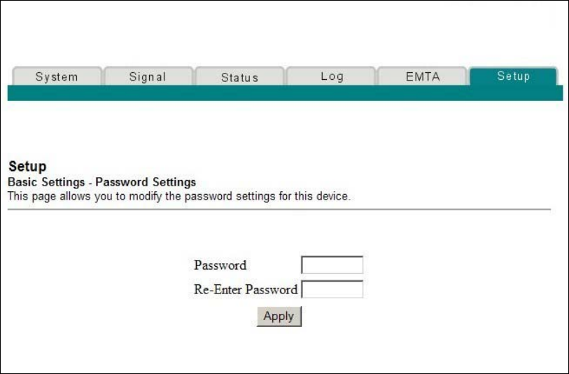
64 4011350 Rev A
How Do I Configure the Wireless Home Gateway?
Configuring Your Password Settings
Use the Basic Settings - Password Settings page to set up a password to restrict
unauthorized persons from accessing to your wireless home gateway settings. Click
Password Settings in the Basic Settings section of the Setup page to access the
Password Settings page.
Notes:
Your gateway modem comes from the factory with no password enabled. We
highly recommend that you set up a user password to prevent unauthorized
users from modifying the settings of your network.
If you do choose to set up a password, use a password that you can easily
remember. Do not forget your password.
Setup Basic Settings - Password Settings Page Example
The following illustration is an example of the Basic Settings - Password Settings
page.
4011350 Rev A 65
How Do I Configure the Wireless Home Gatewa
y
?
To set up your password
To set up your password, type your password in the Password field, and then
re-type your password in the Re-Enter Password field. Then, click Apply to save
your password.
Note: If you set a password, on subsequent access to the WebWizard pages, a screen
similar to the following appears. Do not forget your password. Write your password
and store it in a secure location known only to you.
Configuring Network Time Synchronization
Use the Basic Settings Enable/Disable time synchronization by Network Time
protocol page to enable or disable time synchronization by Network Time protocol.
Note: If you are not familiar with the time configuration procedures detailed in this
section, contact your cable service provider before you attempt to change any of the
wireless home gateway default time synchronization configuration settings.
Click Set Time in the Basic Settings section of the Setup page to access the Basic
Settings Enable/Disable time synchronization by Network Time protocol page.
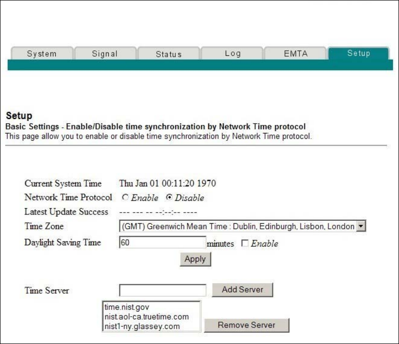
66 4011350 Rev A
How Do I Configure the Wireless Home Gateway?
Setup Basic Settings - Enable/Disable Time Synchronization by
Network Time Protocol Page Example
The following illustration is an example of the Basic Settings Enable/Disable time
synchronization by Network Time protocol page.

4011350 Rev A 67
How Do I Configure the Wireless Home Gatewa
y
?
Setup Basic Settings - Enable/Disable Time Synchronization by
Network Time Protocol Page Description
The following table provides a description of the fields within the Basic Settings
Enable/Disable time synchronization by Network Time protocol page.
Field Name Description
Current System Time Displays the current system time and date
Network Time Protocol Allows you to enable or disable network time
protocol
Note: The gateway will automatically use the time
server in your broadband network. Should there
be no current time displayed or if the network
time is incorrect, enable Network Time Protocol to
use a public Internet time server to set the clock in
the gateway.
Latest Update Success Displays the time and date of the last successful
time update
Time Zone Displays the current time zone. The drop-down
list allows you to select your local time zone.
Daylight Saving Time Allows you to adjust the time during periods
when Daylight Saving Time is in effect. Check the
Enable box to enable or disable this setting.
Note: If the offset for Daylight Savings Time is
other than 60 minutes, enter the offset in the
minutes field.
Time Server Add and delete time server URLs or IP addresses
to and from the list, as required. When using
Network Time Protocol, multiple time servers can
be specified for the gateway to query for time of
day. The gateway will sequentially step through
the listed time servers until it acquires the current
time. There are three well known public time
servers entered as default servers.
Function Keys
Key Description
Apply Saves all additions, edits, and changes
Add Server Allows you to add a network time server
Remove Server Allows you to remove a network time server
68 4011350 Rev A
How Do I Configure the Wireless Home Gateway?
Configuring the Default Network Settings
You can use the default network settings, or, if your system requires different
settings to operate correctly, you can change the default network settings using the
Setup Basic Settings - Network Configuration page.
Note: If you are not familiar with the network configuration procedures detailed in
this section, contact your cable service provider before you attempt to change any of
the wireless home gateway default network configuration settings.
Click Network Configuration in the Basic Settings section of the Setup page to
access the Setup Basic Settings - Network Configuration page.
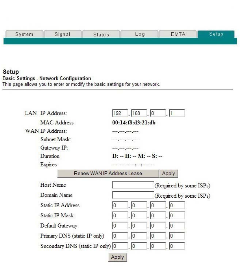
4011350 Rev A 69
How Do I Configure the Wireless Home Gatewa
y
?
Setup Basic Settings - Network Configuration Page Example
The following illustration is an example of the Setup Basic Settings - Network
Configuration page.

70 4011350 Rev A
How Do I Configure the Wireless Home Gateway?
Setup Basic Settings - Network Configuration Page Description
The following table provides a description of the fields within the Setup Basic
Settings - Network Configuration page.
Field Name Description
LAN IP Address Displays the base IP address of the private home LAN
and the WebWizard IP address. Your wireless home
gateway assigns private IP addresses to your attached
computers by its internal dynamic host configuration
protocol (DHCP) server
MAC Address Displays the MAC address for the WAN. The factory
assigned MAC address for the WAN is also referred to
as the WLAN Data MAC
WAN IP Address Displays the public IP address assigned to your
gateway by your ISP. The WAN port will be assigned a
public IP address automatically by your ISP except
when a static IP address is set up as described below.
The WAN IP address will be shared by all the PCs in
your private local area network to access the Internet
Subnet Mask Displays the subnet mask for your WAN port. This
address is automatically assigned to your WAN port by
your ISP except when a static IP address is set up as
described later in this table
Gateway IP Displays a Gateway IP address for your WAN port.
This address is automatically assigned to your WAN
port by your ISP except when a static IP address is set
up as described later in this table
Duration Displays the length of time your WAN IP address is
valid
Expires Displays the date and time your WAN IP address
expires
Host Name Displays the host name that is usually downloaded to
your gateway by your ISP. However, some ISPs require
this information to be entered manually. If manual
entry is required, your ISP will provide the information
for you to enter into this field.
Domain Name Displays the domain name that is usually downloaded
to your gateway by your ISP. However, some ISPs
require this information to be entered manually. If
manual entry is required, your ISP will provide the
information for you to enter into this field.

4011350 Rev A 71
How Do I Configure the Wireless Home Gatewa
y
?
Field Name Description
Static IP Address Manual entry is required. Your ISP will provide the
information for you to enter into this field.
Note: When setting a static IP address, you must enter
the IP address, subnet mask, and default gateway
before the static IP address will become operational.
Static IP Mask Manual entry is required. Your ISP will provide the
information for you to enter into this field.
Default Gateway Manual entry is required, your ISP will provide the
information for you to enter into this field.
Primary DNS
(static IP only)
Manual entry is required. Your ISP will provide the
information for you to enter into this field.
Secondary DNS
(static IP only)
Manual entry is required. Your ISP will provide the
information for you to enter into this field.
Function Keys
The following function keys appear on the Setup Basic Settings - Network
Configuration page.
Key Description
Renew WAN IP
Address Lease
Forces a release and renewal of your WAN IP address
Apply Saves the values you enter into the fields without
closing the screen
Configuring and Managing IP Addresses
Use the Setup Basic Settings - IP Management page to configure how your system
manages and assigns IP addresses in your network.
Note: If you are not familiar with the IP management procedures detailed in this
section, contact your cable service provider before you attempt to change any of the
wireless home gateway default IP management settings.
Click LAN IP Address Management in the Basic Settings section of the Setup page
to access the Setup Basic Settings - IP Management page.
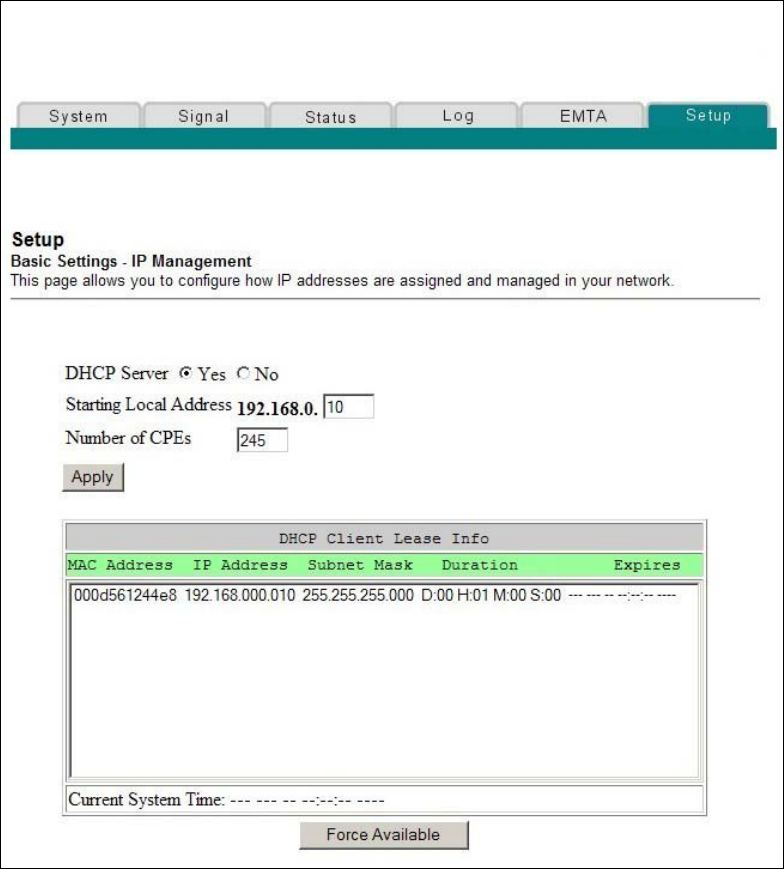
72 4011350 Rev A
How Do I Configure the Wireless Home Gateway?
Setup Basic Settings - IP Management Page Example
The following illustration is an example of the Setup Basic Settings - IP Management
page.

4011350 Rev A 73
How Do I Configure the Wireless Home Gatewa
y
?
Setup Basic Settings - IP Management Page Description
The following tables provide a description of the fields within the Setup Basic
Settings - IP Management page.
Field Name Description
DHCP Server Allows you to enable or disable the DHCP server
in the wireless home gateway
Starting Local Address Displays the starting address used by the built-in
DHCP server to distribute Private LAN IP
addresses. In the example shown, addresses
between 2 and 9 can be used for devices on your
Private LAN that require fixed IP addresses such
as printers or a device assigned as a DMZ host
Note: The LAN IP address ending in 1 is reserved
for the internal gateway server. The LAN IP
address ending in 255 is also reserved and should
not be used for CPE devices
Number of CPEs Enter the maximum number of devices allowed to
connect to the Private LAN.
Note: The Factory Default is 245. The maximum
number of devices is 253. This is the combined
total of addresses reserved for static IP addresses,
for example, the sum of the IP addresses between
2 and the value entered in the Starting Local
Address field and the value entered in the
Number of CPEs field.
Note: The sum of the value entered in the Starting
Local Address field and the value entered in the
Number of CPEs field must always be 255 or less.
DHCP Client Lease Info Displays the MAC address, IP Address, Subnet
Mask, Duration and Expiration date of all devices
issued an IP address by the built-in DHCP server.
This field also displays the current system time
and date
Function Keys
The following function keys appear on the Basic Settings - IP Management page.
Key Description
Apply Saves the values you enter into the fields without
closing the screen
Force Available Forces the release of an IP address for you to
re-use
74 4011350 Rev A
How Do I Configure the Wireless Home Gateway?
Reserving IP Addresses
Use the Setup Basic Settings - Fixed CPE IP Assignment page to reserve IP
addresses. This feature allows you to assign a fixed IP address to any device in your
network by setting static IP addresses in your PC or other network device.
These addresses will be removed from the pool of the IP addresses to be used by
your gateway's DHCP server when issuing IP addresses to devices that are
connected to your local network.
Reserving IP addresses is useful in making sure that there are no IP address conflicts
on the network, for example, two devices using the same IP address. Another
example: when using DMZ Host, the IP address for the DMZ Host should always
have the same IP address.
Note: If you are not familiar with the Fixed CPE IP Assignment procedures detailed
in this section, contact your cable service provider before you attempt to change any
of the wireless home gateway default Fixed CPE IP Assignment settings.
Click Fixed CPE IP Assignment in the Basic Settings section of the Setup page to
access the Setup Basic Settings - Fixed CPE IP Assignment page.
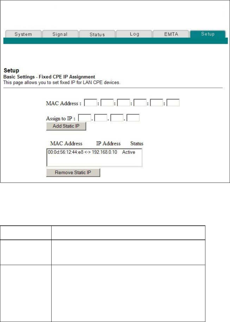
4011350 Rev A 75
How Do I Configure the Wireless Home Gatewa
y
?
Setup Basic Settings - Fixed CPE IP Assignment Page Example
The following illustration is an example of the Setup Basic Settings - Fixed CPE IP
Assignment page.
Setup Basic Settings - Fixed CPE IP Assignment Page Description
The following tables provide a description of the fields within the Setup Basic
Settings - Fixed CPE IP Assignment page.
Field Name Description
MAC Address The MAC address of the PC or device (for example, a
printer) for which you want to reserve a specific IP
address on the network
Assign to IP The IP address you assign to the PC or device for which
you want to reserve a specific IP address on the network.
Only MAC addresses within the range of the gateway's
DHCP address pool can be reserved with this feature.
Note: The factory configuration of your gateway sets
aside IP addresses 192.168.0.2 through 192.168.0.9 for
static IP addresses.
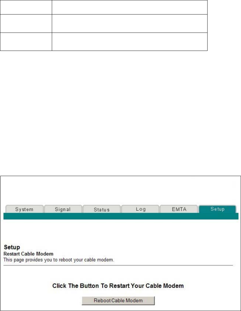
76 4011350 Rev A
How Do I Configure the Wireless Home Gateway?
Function Keys
Key Description
Add Static IP Adds the Static IP address to the list of assigned IP
addresses
Remove Static IP Removes the Static IP address from the list of assigned IP
addresses
Restarting the Gateway Modem
Use the Setup Basic Settings - Restart Cable Modem page to restart your cable
modem.
Click Restart Modem in the Basic Settings section of the Setup page to access the
Basic Settings - Restart Cable Modem page.
Click Reboot Cable Modem to restart the gateway modem.
Note: Restarting your gateway modem does not reset any of the settings.
Setup Basic Settings - Restart Cable Modem Page Example
The following illustration is an example of the Restart Cable Modem page.
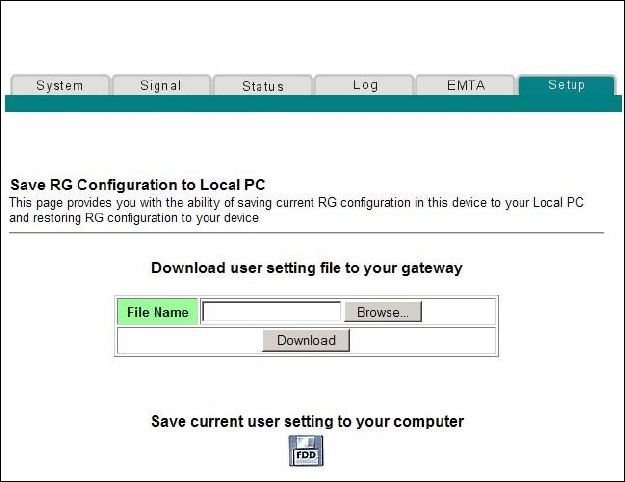
4011350 Rev A 77
How Do I Configure the Wireless Home Gatewa
y
?
Saving Your Configuration
Use the Setup Basic Settings - Save RG Configuration to Local PC page to save your
current cable modem RG configuration to the hard drive on your PC or to a floppy
disk. You will then be able to restore the RG configuration, if necessary.
Note: If you are not familiar with the procedures detailed in this section, contact
your cable service provider before you attempt to change any of the wireless home
gateway default settings.
Click Save Configuration to your PC in the Basic Settings section of the Setup page
to access the Setup Basic Settings - Save RG Configuration to Local PC page.
Setup Basic Settings - Save RG Configuration to Local PC Page
Example
The following illustration is an example of the Setup Basic Settings - Save RG
Configuration to Local PC page.
To Save your current setting to your computer, click the floppy disk icon in the
lower portion of the screen. You will be prompted to provide a file name and
location for the backup configuration file.
To Restore your setting, click Browse and select the backup configuration file name
that you saved on your PC. The path and filename of the backup configuration
appears in the File Name field. Then, click Download to restore your configuration
file. A Download Success message appears when the restore is complete.
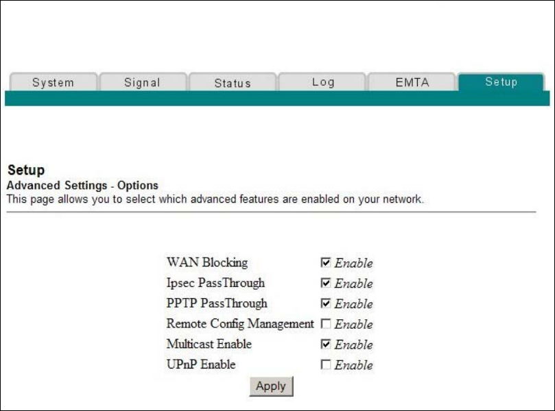
78 4011350 Rev A
How Do I Configure the Wireless Home Gateway?
Enabling and Disabling Advanced Features
Use the Setup Advanced Settings - Options page to enable or disable advanced
features on your network. When the wireless interface is disabled, the transmitter is
turned off.
Note: If you are not familiar with the advanced settings detailed in this section,
contact your cable service provider before you attempt to change any of the wireless
home gateway default advanced options settings.
Click Options in the Advanced Settings section of the Setup page to access the Setup
Advanced Settings - Options page.
Setup Advanced Settings - Options Page Example
The following illustration is an example of the Setup Advanced Settings - Options
page.
Setup Advanced Settings - Options Page Description
The following table provides a description of the fields within the Setup Advanced
Settings - Options page.
Note: If you make changes in the Setup Advanced Settings - Options page, click
Apply to apply and save your new IP address filter settings.

4011350 Rev A 79
How Do I Configure the Wireless Home Gatewa
y
?
Field Name Description
WAN Blocking Checking this box prevents the wireless home gateway
from being visible to the WAN. For example, pings to
the WAN IP address are not returned
Ipsec PassThrough Checking this box allows applications that use IPSec (IP
Security) to pass through the firewall
PPTP PassThrough Checking this box allows applications that use Point to
Point Tunneling Protocol (PPTP) to pass through the
firewall
Remote Config
Management
Checking this box enables Remote Configuration
Management that allows the user or network operator
to view and/or modify the gateway set-up parameters
from a location on the WAN, as opposed to the LAN
side of the gateway. Access to the set-up parameters is
obtained by using the password to access the
WebWizard.
Enable this feature by checking the Remote Config
Management box on the Setup Advanced Settings -
Options page. To access your gateway from a remote
location, you must also know the WAN IP address of
the gateway. To find the WAN IP address, go to the
Network Configuration page under Basic Settings. You
will find the gateway's WAN IP address list on this
page.
Enter the WAN IP address of your gateway into the
address field of any Web browser using the following
format: http://xxx.xxx.xxx.xxx:8080 where
xxx.xxx.xxx.xxx represents the WAN IP address of your
gateway.
Be sure to follow the syntax exactly, and then click Go
or press Enter. Your gateway Web pages will appear on
the remote computer. You will still need to enter your
password to access the Setup pages of your gateway
Note: If you choose to enable (check) this feature, be
sure to set up a user password to prevent unauthorized
access to your gateway settings.
Multicast Enable Checking this box allows multicasts to pass from the
WAN side through to the private network
UPnP Enable Checking this box enables Universal Plug and Play
features
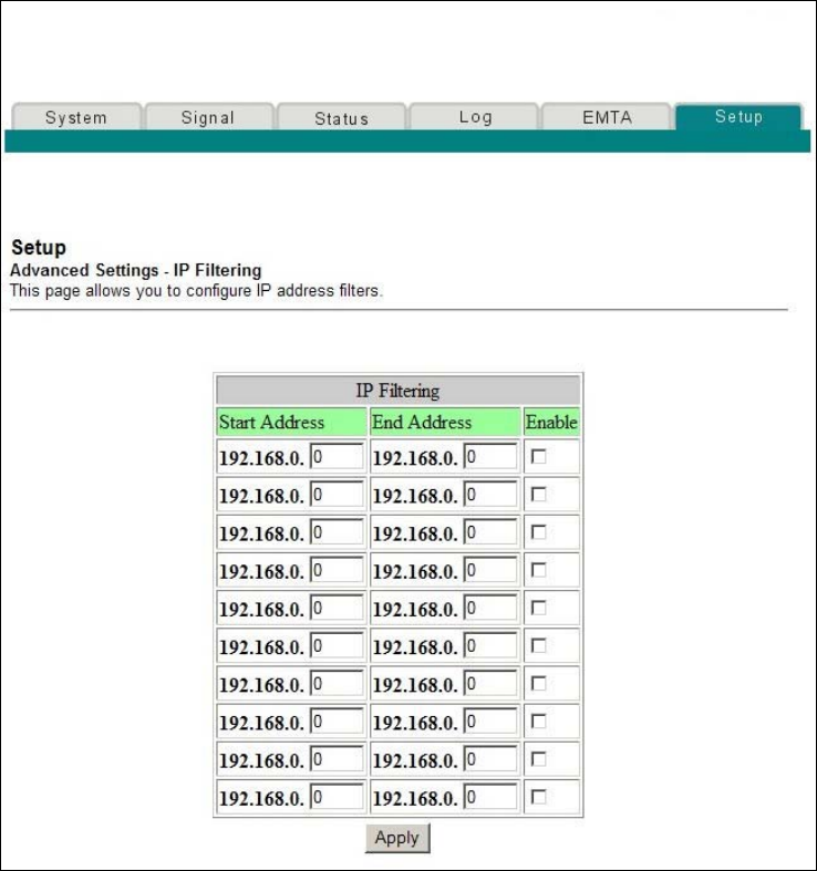
80 4011350 Rev A
How Do I Configure the Wireless Home Gateway?
Configuring IP Address Filters
Use the Setup Advanced Settings - IP Filtering page to configure IP address filters.
These filters block a range of IP addresses from accessing the Internet.
Note: If you are not familiar with the advanced settings detailed in this section,
contact your cable service provider before you attempt to change any of the wireless
home gateway default advanced IP filtering settings.
Click IP Address Filtering in the Advanced Settings section of the Setup page to
access the Setup Advanced Settings - IP Filtering page.
Setup Advanced Settings - IP Filtering Page Example
The following illustration is an example of the Setup Advanced Settings - IP Filtering
page.
4011350 Rev A 81
How Do I Configure the Wireless Home Gatewa
y
?
Setup Advanced Settings - IP Filtering Page Description
Use this page to specify and enable a range of IP addresses that cannot have access
to the Internet. Click Apply to apply and save your new IP address filter settings.
Configuring MAC Address Filters
Use the Setup Advanced Settings - MAC Filtering page to configure MAC address
filters. These filters allow you to deny or block access to the Internet by the
individual MAC addresses listed in the table. You can also prevent individual PCs
from sending outgoing TCP/UDP traffic to the WAN using their MAC address.
Note: If you are not familiar with the advanced settings detailed in this section,
contact your cable service provider before you attempt to change any of the wireless
home gateway default advanced MAC filtering settings.
Click MAC Address Filtering in the Advanced Settings section of the Setup page to
access the Setup Advanced Settings - MAC Filtering page.
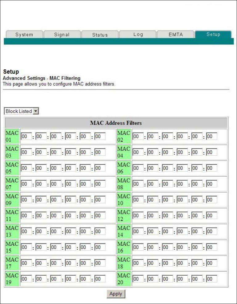
82 4011350 Rev A
How Do I Configure the Wireless Home Gateway?
Setup Advanced Settings - MAC Filtering Page Example
The following illustration is an example of the Setup Advanced Settings - MAC
Filtering page.

4011350 Rev A 83
How Do I Configure the Wireless Home Gatewa
y
?
Setup Advanced Settings - MAC Filtering Page Description
Use this page to enter the MAC address or MAC addresses of devices whose Internet
access you want to control. Click Apply to apply and save your new MAC address
filter settings.
Setting Up MAC Address Filters
The Block/Pass drop down menu allows you to block or pass Internet access to the
MAC addresses of the devices you list in the MAC Address Filters table. The
following table describes the function of the Block/Pass drop down menu.
Field Name Description
Block Listed (Default) Select Block to deny Internet access to the MAC
addresses of the devices you list in the table. All
other MAC addresses will be allowed Internet
access.
Pass Select Pass to allow Internet access only to the
MAC addresses of the devices you list in the table.
Any MAC addresses not listed in the table will be
denied Internet access.
Configuring and Enabling TCP and UDP Port Filters
Use the Setup Advanced Settings - Port Filtering page to configure and enable TCP
and UDP port filters. These filters prevent a range of TCP/UDP ports from accessing
the Internet. You can also prevent PCs from sending outgoing TCP/UDP traffic to
the WAN on specific IP port numbers. This filter is not IP address- or MAC address-
specific. The system blocks the specified port ranges for all PCs.
Note: If you are not familiar with the advanced settings detailed in this section,
contact your cable service provider before you attempt to change any of the wireless
home gateway default advanced port filtering settings.
Click Port Filtering in the Advanced Settings section of the Setup page to access the
Setup Advanced Settings - Port Filtering page.
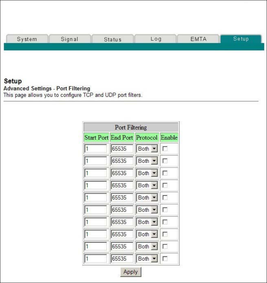
84 4011350 Rev A
How Do I Configure the Wireless Home Gateway?
Setup Advanced Settings - Port Filtering Page Example
The following illustration is an example of the Setup Advanced Settings - Port
Filtering page.
Setup Advanced Settings - Port Filtering Page Description
Use this page to enter and enable the desired port filtering ranges and protocols in
the appropriate fields and then click Apply to apply and save your new port
filtering settings.
4011350 Rev A 85
How Do I Configure the Wireless Home Gatewa
y
?
Configuring Port Forwarding for Local IP Addresses
Use the Setup Advanced Settings - Port Forwarding page to configure port
forwarding for local IP addresses. Port forwarding allows you to run a server on the
LAN by specifying the mapping of TCP/UDP ports to a local PC. You must also set
up a fixed private LAN IP address for the destination device.
Note: If you are not familiar with the advanced settings detailed in this section,
contact your cable service provider before you attempt to change any of the wireless
home gateway default advanced port forwarding settings.
Click Port Forwarding in the Advanced Settings section of the Setup page to access
the Setup Advanced Settings - Port Forwarding page.
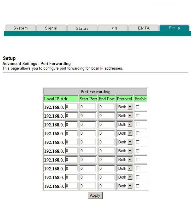
86 4011350 Rev A
How Do I Configure the Wireless Home Gateway?
Setup Advanced Settings - Port Forwarding Page Example
The following illustration is an example of the Setup Advanced Settings - Port
Forwarding page.
4011350 Rev A 87
How Do I Configure the Wireless Home Gatewa
y
?
Setup Advanced Settings - Port Forwarding Page Description
The following example illustrates how to use the port forwarding feature to
configure the Microsoft X-Box Online Live for Internet gaming.
Note: For most widely used applications (including Microsoft X-Box Online Live),
the built-in firewall automatically maps and opens ports required for that
application while the application is in use.
1. Set the device to be used for port forward to a fixed IP address, for
example, 192.168.0.5.
2. In the first entry of the Port Forwarding area of the page, enter the
same IP address (192.168.0.5) in the Local IP Address field.
3. In the same row, enter the appropriate port numbers in the Start
Port and End Port fields.
4. In the same row, select the appropriate protocol from the drop-
down list in the Protocol field, and then select the box in the
Enable field.
5. To add additional ports, repeat steps 1 through 4, and then go to
step 6.
6. Click Apply to apply and save your new port forwarding settings.
Configuring TCP/UDP Port Triggers
Use the Setup Advanced Settings - Port Triggers page to configure TCP/UDP port
triggers. Port triggering is similar to port forwarding but is dynamic. In other words,
the system does not hold the ports open indefinitely. For example, when the wireless
home gateway detects outgoing data on a specific IP port number set in the “Trigger
Range,” the resulting ports set in the “Target Range” will open for incoming data. If
the system detects no outgoing traffic on the “Trigger Range” ports for a period of 10
minutes, the “Target Range” ports close. This is a safer method for opening specific
ports for special applications, such as, video conferencing programs, interactive
gaming, and file transfer in chat programs. This is safe because the ports are
dynamically triggered and not held open continuously or left open erroneously by
the router administrator. Therefore, these ports are not exposed and vulnerable for
potential hackers to discover.
Note: If you are not familiar with the advanced settings detailed in this section,
contact your cable service provider before you attempt to change any of the wireless
home gateway default advanced port triggers settings.
Click Port Triggers in the Advanced Settings section of the Setup page to access the
Setup Advanced Settings - Port Triggers page.
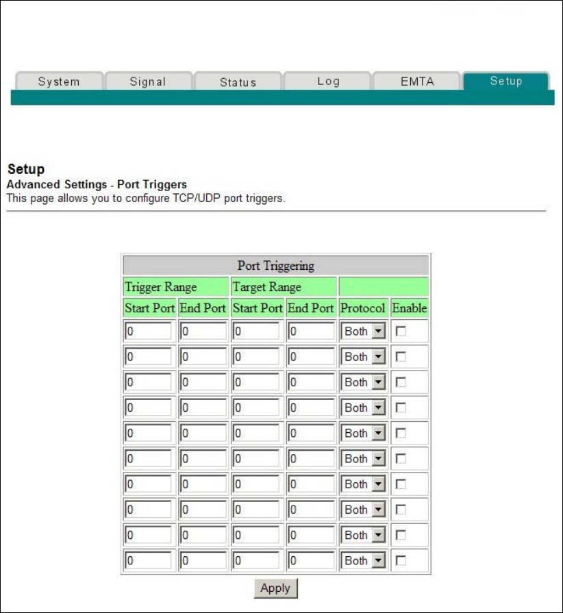
88 4011350 Rev A
How Do I Configure the Wireless Home Gateway?
Setup Advanced Settings - Port Triggers Page Example
The following illustration is an example of the Setup Advanced Settings - Port
Triggers page.
4011350 Rev A 89
How Do I Configure the Wireless Home Gatewa
y
?
Setup Advanced Settings - Port Triggers Page Description
Use this page to enter and enable the port forwarding trigger and target range start
and end ports along with protocol information in the appropriate fields. The
following example illustrates how to use the port triggering feature to configure the
Microsoft X-Box Online Live for Internet gaming.
Note: For most widely used applications (including Microsoft X-Box Online Live),
the built-in firewall automatically maps and opens ports required for that
application while the application is in use.
1. In the first row, enter 88 in both Start Port and End Port fields.
2. In the same row, select UDP from the drop-down list in the
Protocol field, and then select the box in the Enable field.
3. In the second row, enter 3074 in both Start Port and End Port
fields.
4. In the same row as the second entry, select Both, and then
select the box in the Enable field.
5. Click Apply to apply and save your new port forwarding
settings.
Configuring the DMZ Host
Use the Setup Advanced Settings - DMZ Host page to configure an IP address that is
visible to the WAN. DMZ hosting is commonly referred to as “exposed host,” and
allows you to specify the “default” recipient of WAN traffic that Network Address
Translation (NAT) is unable to translate to a known local PC. DMZ allows one IP
address to be unprotected while others remain protected.
Note: If you are not familiar with the advanced settings detailed in this section,
contact your cable service provider before you attempt to change any of the wireless
home gateway default advanced DMZ host settings.
Click DMZ Host in the Advanced Settings section of the Setup page to access the
Setup Advanced Settings - DMZ Host page.
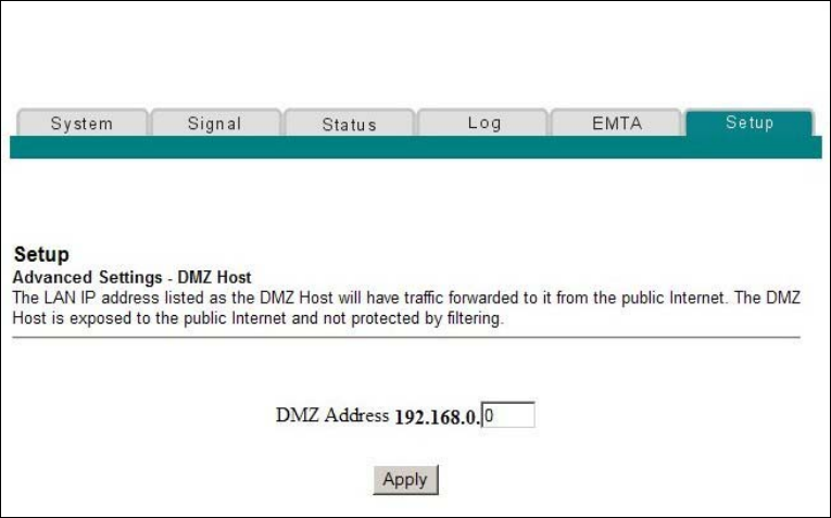
90 4011350 Rev A
How Do I Configure the Wireless Home Gateway?
Setup Advanced Settings - DMZ Host Page Example
The following illustration is an example of the Setup Advanced Settings - DMZ Host
page.
Setup Advanced Settings - DMZ Host Page Description
Use this page to place a Private LAN IP device, for example, an FTP, Mail, or Web
server directly on the Internet (bypassing the firewall). You set the server with a
fixed IP address as a DMZ Host by entering its IP address in the DMZ Address field.
Make sure the IP address used is not in the range of addresses delivered by the built-
in DHCP server. After setting up a DMZ Host, all ports on this device are open to
the Internet. You may configure only one PC to be the DMZ host. DMZ is generally
used for PCs running “problem” applications that use random port numbers and do
not function correctly with the specific port triggers or port forwarding setups
described earlier in this guide. After entering a DMZ Address, click Apply to apply
and save your new DMZ Host setting.
Configuring Firewall Protection
Use the Setup Firewall - Options page to configure Web page filtering and firewall
protection. This page allows you to enable various firewall protection filters.
Note: If you are not familiar with the advanced settings detailed in this section,
contact your cable service provider before you attempt to change any of the wireless
home gateway default firewall options settings.
Click Options in the Firewall section of the Setup page to access the Setup Firewall -
Options page.
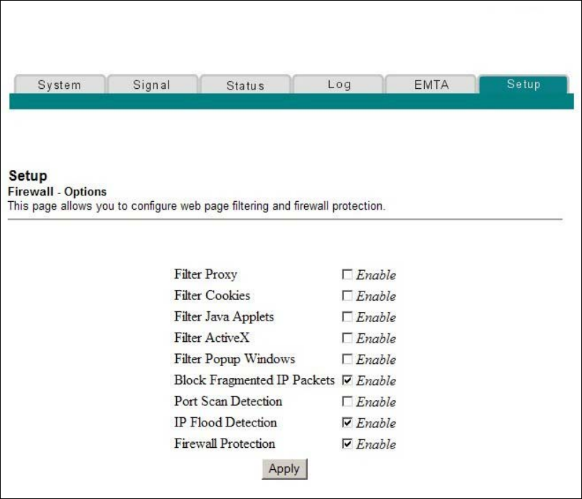
4011350 Rev A 91
How Do I Configure the Wireless Home Gatewa
y
?
Setup Firewall - Options Page Example
The following illustration is an example of the Setup Firewall - Options page.

92 4011350 Rev A
How Do I Configure the Wireless Home Gateway?
Setup Firewall - Options Page Description
This section describes the section headings and fields descriptions of the Setup
Firewall - Options page.
Note: If you make changes in any of the fields in the Setup Firewall - Options page,
click Apply to apply and save your Firewall settings.
The following table provides a description of each field name within the Setup
Firewall - Options page.
Field Name Description
Filter Proxy Enables/disables proxy
Filter Cookies Enables/disables cookie blocking. This feature filters
the unsolicited delivery of cookies to devices from the
Internet to devices in your private local network.
Cookies are computer files that contain personal
information or Web surfing behavior data.
Filter Java Applets Enables/disables java applets. This feature helps to
protect the devices in your private network from
irritating or malicious Java applets that are sent,
unsolicited, to devices in your private network from
the Internet. These applets run automatically when
they are received by a PC.
Filter ActiveX Enables/disables ActiveX controls. This feature helps
to protect the devices in your private network from
irritating or malicious ActiveX controls that are sent,
unsolicited, to devices in your private network from
the Internet. These ActiveX controls run automatically
when they are received by a PC.
Filter Popup
Windows
Enables/disables popup windows. Some commonly
used applications employ popup windows as part of
the application. If you disable popup windows, it may
interfere with some of these applications.
Block Fragmented IP
Packets
Enables/disables filtering of fragmented IP packets.
This feature helps protect your private local network
from Internet based denial of service attacks.
Port Scan Detection Enables/disables the gateway from responding to
Internet based port scans. This feature is designed to
protect your private local network from Internet
based hackers who attempt to gain unsolicited access
your network by detecting open IP ports on your
gateway.

4011350 Rev A 93
How Do I Configure the Wireless Home Gatewa
y
?
Field Name Description
IP Flood Detection Blocks malicious devices that are attempting to flood
devices or networks with illegal broadcast packets.
Also referred to as “broadcast storm.”
Firewall Protection Enables/disables the firewall. When the firewall is
enabled, the firewall will allow most commonly used
applications to automatically open IP ports and pass
data without any special setup or manual port
configuration.
Configuring Firewall Event Logging and E-mail Alerts
Use the Setup Firewall - Event Logging page to access the firewall event log and
allows you to enter your e-mail address in order for you to receive e-mail alerts
related to firewall attacks by hackers.
Note: If you are not familiar with the settings detailed in this section, contact your
cable service provider before you attempt to change any of the wireless home
gateway default firewall event logging settings.
Click Event Logging in the Firewall section of the Setup page to access the Setup
Firewall - Event Logging page.
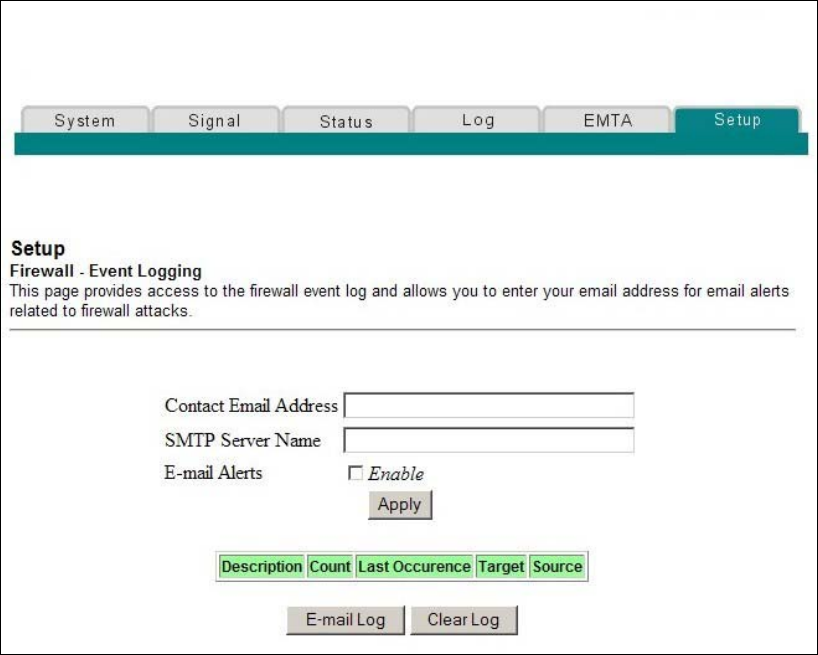
94 4011350 Rev A
How Do I Configure the Wireless Home Gateway?
Setup Firewall - Event Logging Page Example
The following illustration is an example of the Setup Firewall - Event Logging page.
Setup Firewall - Event Logging Page Description
The Setup Firewall - Event Logging page shows events captured by the firewall. The
log displays the following items:
Description of the event
Number of events that have occurred
Last occurrence of an event
Target and source addresses
You can configure the system to e-mail log events to the administrator in order for
the administrator to monitor the firewall.
This section describes the section headings and fields descriptions of the Setup
Firewall - Event Logging page.

4011350 Rev A 95
How Do I Configure the Wireless Home Gatewa
y
?
Field Name Description
Enable Email
Address
Allows you to enter the e-mail address of the person
who monitors the firewall. When an event occurs, it
will be logged and an email will be sent to this
address automatically reporting the event.
SMTP Server Name Allows you to enter the mail server name of your
outgoing mail server, or the mail server of your
Internet service provider (ISP)
E-mail Alerts Allows you to enable or disable sending e-mail alerts
Description Describes what event was detected by the gateway's
firewall
Count Displays the number of times the event has been
detected
Last Occurrence Displays the time the last occurrence of this event was
detected
Target Displays the IP address of the device in your private
local network to which the event was directed along
with the IP port number targeted by the event
Source Displays the IP address of the Internet based source of
the event along with the IP port number used by that
device
Function Keys
The following function keys appear on the Setup Firewall - Event Logging page.
Key Description
Apply Saves the values you enter into the fields without
closing the screen
E-mail Log Allows you to force the system to send an e-mail alert
even if the E-mail Alerts box is left unchecked
Clear Log Allows you to clear all entries in the log
96 4011350 Rev A
How Do I Configure the Wireless Home Gateway?
Configuring Parental Control
Use the Setup Parental Control - User Setup page to configure parental controls on
the wireless home gateway, and to add or delete the individuals who are authorized
to set parental controls.
Note: If you are not familiar with the settings detailed in this section, contact your
cable service provider before you attempt to change any of the wireless home
gateway default parental control settings.
Click User Setup in the Parental Control section of the Setup page to access the
Setup Parental Control - User Setup page.
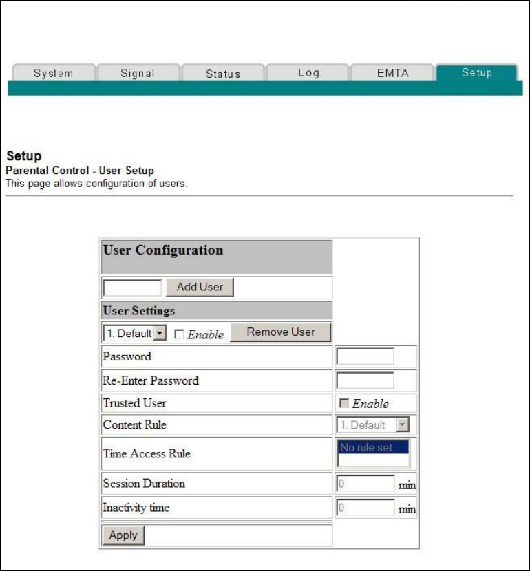
4011350 Rev A 97
How Do I Configure the Wireless Home Gatewa
y
?
Setup Parental Control - User Setup Page Example
The following illustration is an example of the Setup Parental Control - User Setup
page.
Setup Parental Control - User Setup Page Description
This section describes the section headings and fields descriptions of the Setup
Parental Control - User Setup page. This page allows you to set up user profiles.
Each profile can be assigned customized levels of Internet access as defined by the
access rules assigned to that user's profile.
Note: Once you define and enable user profiles, each user must sign-on each time
they wish to access the Internet. The user can sign-on when the pop-up sign-on
screen appears in their Web browser. The user must enter their correct user name
and password in order to gain Internet access.

98 4011350 Rev A
How Do I Configure the Wireless Home Gateway?
Important!
Make sure to disable pop-up blockers on your Web browser when using user
profiles.
User names and passwords are case-sensitive.
Field Name Description
Add User Allows you to add a new user profile. Enter the name of
the user and click the Add User button to add the user
to the list.
User Settings Allows you to edit a user profile by using the drop-
down menu to edit a user profile. The drop-down menu
allows you to recall the profile to be edited. User names
and passwords are case-sensitive.
Make sure to check the Enable box to activate the user
profile. If a profile is not active, that user will not have
any access to the Internet.
To remove a user profile, use the drop-down menu to
select the user to be removed and click the Remove
User button.
Password Enter the selected user's password in this field. Each
user must enter their User Name and Password each
time they use the Internet. User names and passwords
are case-sensitive.
Note: The Gateway will allow each user access to the
Internet, subject to the rules selected on this page for
that user.
Re-Enter Password Re-enter the same password for confirmation of the
password in the previous field.
Trusted User Check this box if the currently selected user is to be
designated a trusted user. Trusted users are not subject
to Internet access rules.
Content Rule Select the Content Rule for the current user profile.
Content Rules must first be defined by going to the
Rules Configuration page. You can access the Rule
Configuration page by clicking on the “Basic Rules” link
under the Parental Control section of the Setup page.
Time Access Rule Select the Time Access Rule for the current user profile.
Time Access Rules must first be defined by going to the
Time of Day Filter page. You can access the Time of Day
Filter page by clicking on the “Time of Day Rules” link
under the Parental Control section of the Setup page.

4011350 Rev A 99
How Do I Configure the Wireless Home Gatewa
y
?
Field Name Description
Session Duration 1440 minutes (factory default).
Enter the amount of time in minutes that the user will
be granted Internet access beginning at the time they
sign on using their User Name and Password.
Note: Set the Session Duration to 0 (zero) to prevent
session timeout.
Inactivity time 60 minutes (factory default).
Enter the amount of time during a user session where
there is no Internet access activity, indicating that the
user is no longer online. If the inactivity timer is
triggered, the user session will be closed automatically.
In order to regain Internet access, the user must log in
again with their User Name and Password.
Note: Set the Inactivity time value to 0 (zero) to prevent
timeout due to inactivity.
Available Rules Lists available rules. Apply a rule by selecting it from
the list and adding it to the current user profile.
Note: Create rules using the Parental Control Setup
pages that follow next.
Current Used Rules Lists rules in use for the current user profile. You can
apply a maximum of four rules to each user profile.
Function Keys
The following function keys appear on the Setup Parental Control - User Setup page.
Key Description
Add User Adds and saves a new user to the list of user profiles
Remove User Removes the selected user from the list of user profiles
Apply Saves all additions, edits, and changes
Configuring Parental Controls Basic Rules
Use the Setup Parental Control - Basic Setup page to select the rules that block
certain Internet content and certain Web sites.
Note: If you are not familiar with the settings detailed in this section, contact your
cable service provider before you attempt to change any of the wireless home
gateway default parental control settings.
Click Basic Rules in the Parental Control section of the Setup page to access the
Setup Parental Control - Basic Setup page.
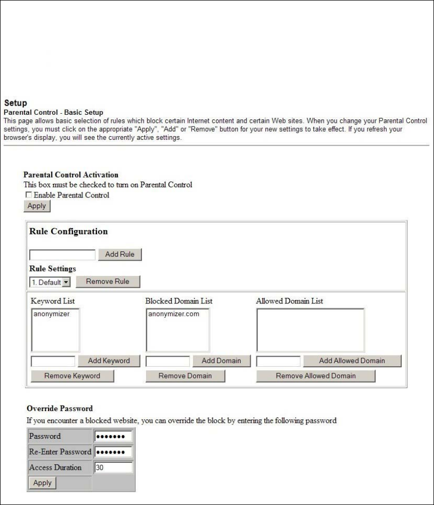
100 4011350 Rev A
How Do I Configure the Wireless Home Gateway?
Setup Parental Control - Basic Setup Page Example
The following illustration is an example of the Setup Parental Control - Basic Setup
page.

4011350 Rev A 101
How Do I Configure the Wireless Home Gatewa
y
?
Setup Parental Control - Basic Setup Page Description
This section describes the section headings and fields descriptions of the Setup
Parental Control - Basic Setup page. This page allows you to create Internet access
rules based on the content found in the URLs of Internet sites.
Field Name Description
Rule Configuration Allows you to add a new content rule. Enter the name
of the rule and click the Add Rule button to add the
content rule to the list. Content rules are used to
restrict Internet access based on IP addresses,
domains, and keywords found in the URLs of Internet
sites.
Note: It may be useful to set up your first rule as “No
Rule,” without any restrictions or settings. This setting
will allow you to assign “No Rule” status to users
who are not subject to “content-related” access
restrictions.
Rule Settings Allows you to edit a content rule by using the drop-
down menu to recall the rule to be edited.
To remove a user profile, use the drop-down menu to
select the rule to be removed and click on the Remove
Rule button.
Keyword List Allows you to create a list of keywords. Any attempt
to access a URL that contains any of the keywords in
this list will be blocked by the gateway.
Blocked Domain List Allows you to create a list of Domains that the
gateway should block access to. Any attempt to access
any of the Domains in this list will be blocked by the
gateway.
Allowed Domain List Allows you to create a list of Domains to which the
gateway allows access.
Override Password Allows you to create a password to temporarily
override user access restrictions to a blocked Internet
site.
Re-enter Password Re-enter the same password for confirmation of the
override password in the previous field.
Duration Allows you to designate an amount of time in minutes
that the Override password will allow temporary
access to a restricted Internet site.

102 4011350 Rev A
How Do I Configure the Wireless Home Gateway?
Function Keys
The following function keys appear on the Setup Parental Control - Basic Setup
page.
Key Description
Add Rule Adds and saves a new Rule to the list of content Rules
Remove Rule Removes the selected rule from the content rule list
Add/Remove
Keyword
Allows you to add new keywords to the list or to
delete selected keywords from the list
Add/Remove
Domain
Allows you to add new domains to the list or to delete
selected domains from the list
Add/Remove
Allowed Domain
Allows you to add new domains to the list or to delete
selected domains from the list
Apply Saves all additions, edits, and changes
To use keyword and domain blocking
Keyword and Domain blocking allows you to restrict access to Internet sites by
blocking access to those sites based on a word or a text string contained in the URLs
used to access those Internet sites.
Domain blocking allows you to restrict access to Web sites based on the site's
Domain Name. The Domain Name is the portion of the URL that precedes the
familiar .COM, .ORG, or .GOV extension.
Keyword blocking allows you to block access to Internet sites based on a Keyword
or text string being present anywhere in the URL, not just in the Domain Name.
Note: The Domain blocking feature blocks access to any Domain in the Domain List.
It will also block Domains, any portion of which contains an exact match to entries in
the list.
For example, if you enter example.com as a Domain, any site that contains
“example.com” will be blocked. Generally, you do not want to include “www.” in a
Domain Name since doing so limits the blocking to only the site that matches that
Domain Name exactly. For instance, if you enter www.example.com into the list,
only the one site that matches that name exactly will be blocked. Consequently, if
you do not include the “www.,” then all sites within and associated with
“example.com” will be blocked.
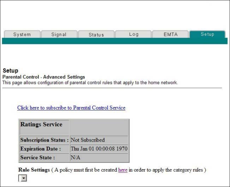
4011350 Rev A 103
How Do I Configure the Wireless Home Gatewa
y
?
Configuring Parental Control Advanced Settings
Use the Setup Parental Control - Advanced Settings page to configure parental
control rules that apply to the home network.
Note: If you are not familiar with the settings detailed in this section, contact your
cable service provider before you attempt to change any of the wireless home
gateway default parental control settings.
Click Advanced Rules in the Parental Control section of the Setup page to access the
Setup Parental Control - Advanced Settings page.
Setup Parental Control - Advanced Settings Page Example
The following illustration is an example of the Setup Parental Control - Advanced
Settings page.

104 4011350 Rev A
How Do I Configure the Wireless Home Gateway?
Setup Parental Control - Advanced Settings Page Description
This section describes the section headings and fields descriptions of the Setup
Parental Control - Advanced Settings page.
Note: A subscription is required. You must subscribe to the Parental Control Service
by clicking on the link displayed on the Setup Parental Control Advanced Settings
page.
Field Name Description
Ratings Service Your Internet Service provider may offer advanced
parental control services. Advanced parental control
utilizes Internet based servers to rate Web sites for
undesirable content. The rating service will evaluate
and rate every Internet site that a user attempts to
access through your gateway. The process is extremely
fast and does not affect the time it takes to bring up
Internet sites on your browser.
If a category (or categories) is selected from the rating
service category list, then access to any Internet site
that has a rating that matches the selected category will
be blocked by the gateway.
Subscription Status Displays the following information regarding your
subscription status:
Active - Subscription to a rating service is active.
Inactive (factory default) - No rating service
available.
Expiration Date Displays the date the Parental Control Service
subscription expires.
Service State Displays the type of subscription service to which you
are subscribed.
Rules Settings Allows you to attach the selected rating service
categories to a previously defined parental control
access rule.
Use the Rule Setting drop down menu to select the rule
to which you want to apply the current set of selected
categories.
4011350 Rev A 105
How Do I Configure the Wireless Home Gatewa
y
?
Configuring Parental Control Time of Day Access Filters
Use the Setup Parental Control - Time of Day Access Filter page to configure Web
access filters to block all Internet traffic to and from specific network devices based
on day of week and time of day settings that you select.
Note: If you are not familiar with the settings detailed in this section, contact your
cable service provider before you attempt to change any of the wireless home
gateway default parental control settings.
Click Time of Day Rules in the Parental Control section of the Setup page to access
the Parental Control - Time of Day Access Filter page.
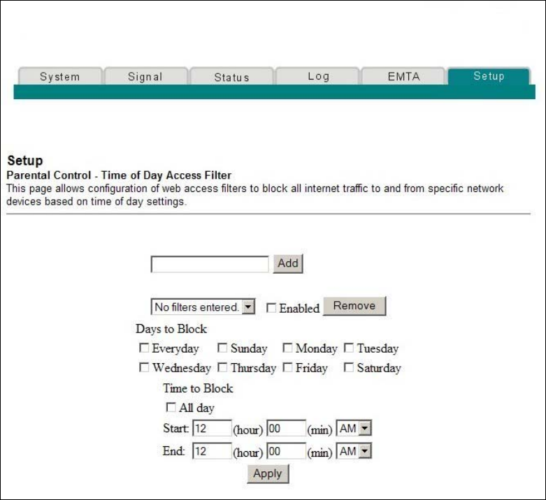
106 4011350 Rev A
How Do I Configure the Wireless Home Gateway?
Setup Parental Control - Time of Day Access Filter Page Example
The following illustration is an example of the Setup Parental Control - Time of Day
Access Filter page.
Note: The wireless home gateway uses the network time of day clock that is
managed by your data service provider. The time of day clock must be accurate and
represent the time of day in your time zone for this feature to operate properly.
Verify that the Status and Set Time pages reflect the correct time of day. If they do
not reflect the correct time of day, contact your data service provider. You can also
adjust your settings to account for the difference.

4011350 Rev A 107
How Do I Configure the Wireless Home Gatewa
y
?
Function Keys
The following function keys appear on the Setup Parental Control - Time of Day
Access Filter page.
Key Description
Add Allows you to add a new Time of Day access filter or
rule. Enter the name of the filter and click the Add key
to add the filter to the list. Time of Day rules are used
to restrict Internet access based on the day and time.
Remove Removes the selected filter from the Time of Day filter
list.
Apply Saves all additions, edits, and changes.
Configure Parental Control Event Reporting
Use the Setup Parental Control - Event Log page to view events captured by the
parental control event-reporting feature.
Note: If you are not familiar with the settings detailed in this section, contact your
cable service provider before you attempt to change any of the wireless home
gateway default parental control settings.
Click Local Log in the Parental Control section of the Setup page to access the Setup
Parental Control - Event Log page.
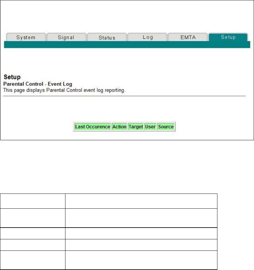
108 4011350 Rev A
How Do I Configure the Wireless Home Gateway?
Setup Parental Control - Event Log Page Example
The following illustration is an example of the Setup Parental Control - Event Log
page.
Setup Parental Control - Event Log Page Description
This section describes the section headings and fields descriptions of the Setup
Parental Control - Event Log page. This page allows you to track, by user, any
attempts made by that user to access Internet sites that are restricted.
Field Name Description
Last Occurrence Displays the time of the most recent attempt to access
a restricted Internet site
Target Displays the URL of the restricted site
User Displays the user who attempted a restricted site
Source Displays the IP address of the PC which was used
when attempting to access a restricted Web site
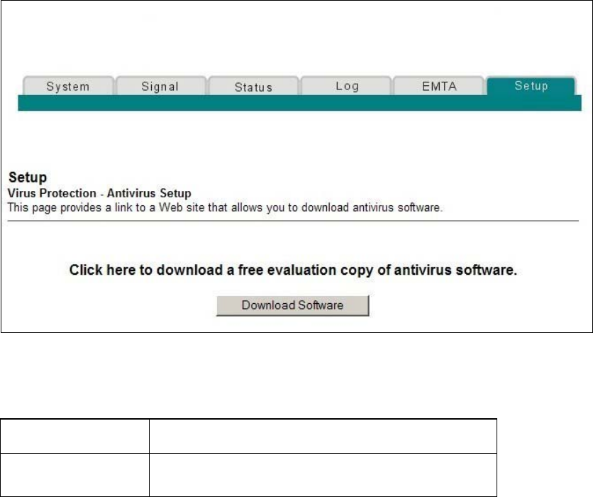
4011350 Rev A 109
How Do I Configure the Wireless Home Gatewa
y
?
Configuring Virus Protection
Use the Setup Virus Protection - Antivirus Setup page to access a Web site that
allows you to download a free evaluation copy of antivirus software.
Important! The antivirus software must be installed on all PCs or computers that are
connected to the wireless home gateway.
Note: If you are not familiar with the settings detailed in this section, contact your
cable service provider before you attempt to change any of the wireless home
gateway default antivirus settings.
Click Antivirus Setup in the Virus Protection section of the Setup page to access the
Setup Virus Protection - Antivirus Setup page.
Setup Virus Protection - Antivirus Setup Page Example
The following illustration is an example of the Setup Virus Protection - Antivirus
Setup page.
Function Key
The following function key appears on the Setup Virus Protection - Antivirus Setup
page.
Key Description
Download Software Click to download a free evaluation copy of antivirus
software.
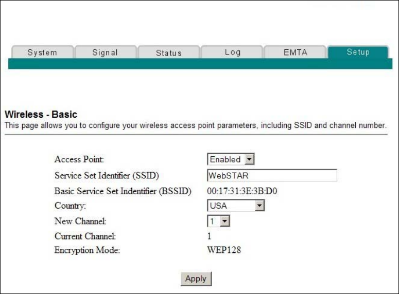
110 4011350 Rev A
How Do I Configure the Wireless Home Gateway?
Configuring Your Wireless Access Point Parameters
Use the Setup Wireless - Basic page to configure your wireless access point (WAP)
parameters, included SSID and channel number.
Note: If you are not familiar with the advanced settings detailed in this section,
contact your cable service provider before you attempt to change any of the wireless
home gateway default wireless basic settings.
Click Basic in the Wireless section of the Setup page to access the Setup Wireless -
Basic page.
Setup Wireless - Basic Page Example
The following illustration is an example of the Setup Wireless - Basic page showing
the factory default settings.

4011350 Rev A 111
How Do I Configure the Wireless Home Gatewa
y
?
Setup Wireless - Basic Page Description
This section describes the section headings and fields descriptions of the Setup
Wireless - Basic page.
Note: If you make changes in the Setup Wireless - Basic page, click Apply to apply
and save your wireless basic settings.
Field Name Description
Access Point Allows you to turn the access point on the gateway on or
off
Service Set Identifier
(SSID)
The name assigned to this access point
Note: The factory default for the SSID field should
contain the product name WebSTAR.
Basic Service Set
Identifier (BSSID)
The MAC address of the access point
Country Allows you to select the country in which you are using
your access point
New Channel (1-11) Allows setting a communications channel for your
access point
Note: Wireless networking channels overlap. Channels
1, 6, and 11 do not overlap with each other. For best
performance, select one of these channels. If there are
other access points in use in the area, select one of these
channels that is farthest away from the other access
points.
Example: If channel 8 is in use by another access point,
use channel 1 for your wireless network.
Note: If your wireless network is not operating correctly,
or if external devices are interfering with your signal,
select a different channel. Use your PC wireless utility
software to scan for other access points in your area.
Current Channel Present channel the WAP is using
Encryption Mode Shows current encryption mode
112 4011350 Rev A
How Do I Configure the Wireless Home Gateway?
Configuring Your Wireless Network Security and Encryption
Parameters
Use the Setup Wireless - Security page to configure your WAP wireless equivalent
privacy (WEP) encryption keys and authentication.
Note: If you are not familiar with the advanced settings detailed in this section,
contact your cable service provider before you attempt to change any of the wireless
home gateway default wireless security settings.
Click Security in the Wireless section of the Setup page to access the Setup Wireless -
Security page.
Important! Your wireless home gateway ships from the factory with 128-bit WEP
encryption enabled to provide you with a basic level of wireless network security. To
gain initial access to your wireless network, select 128-bit WEP encryption on your
computer's wireless adapter and enter the 128-bit encryption key to match the key
setup in your gateway. The factory default 128-bit key in the gateway is 26 zeros (see
the following example). You can continue to use this factory default key. However,
to maximize your wireless security, it is highly recommended that you use
something other than the factory default key.
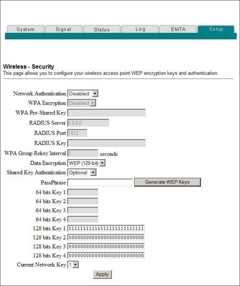
4011350 Rev A 113
How Do I Configure the Wireless Home Gatewa
y
?
Setup Wireless - Security Page Example
The following illustration is an example of the Setup Wireless - Security page.
Setup Wireless - Security Page Description
This section describes the section headings and fields descriptions of the Setup
Wireless - Security page.
Note: If you make changes in the Setup Wireless - Security page, click Apply to
apply and save your wireless security settings.

114 4011350 Rev A
How Do I Configure the Wireless Home Gateway?
Field Name Description
Network
Authentication
Network Authentication allows only authorized
users to gain access to your wireless network. Only
users with an authorized user name, password, or
pre-shared key are allowed access to the wireless
network.
Select from the following Network Authentication
protocols:
Disabled (factory default)
802.1x
WPA
WPA-PSK
Note: Network Authentication restricts access to
your wireless network to only authorized computers
or users. Authentication does not protect the data
you send over the wireless network connection. You
must enable encryption to protect data that is
transmitted over your wireless network.
WPA Pre-Shared Key Allows you to set a WPA Pre-Shared encryption key.
Enter a text string in this field. The text string or
phrase is used to generate a unique set of encryption
keys for your network. Use this string to set up
wireless devices in your network.
The PSK can be either a text string or a 64
character hexadecimal number.
The text string must be an ASCII character string
with a minimum of 8 characters but no more
than 63.
Note: Not all wireless adapter devices support PSK.
For these devices, you must enter the encryption
keys exactly as they appear in the in wireless
gateway fields in the preceding illustration of the
Setup Wireless Security page.
WPA Group Rekey
Interval
Allows you to set the WPA Group Rekey Interval in
seconds. This only applies when WPA and WPA-
PSK Network Authentication is enabled.
Set this value to 0 (factory default) to disable
periodic rekeying. The valid range is 1 to
4,294,967,295 seconds.

4011350 Rev A 115
How Do I Configure the Wireless Home Gatewa
y
?
Field Name Description
RADIUS Server Allows you to enter the IP address of the RADIUS
server used for authentication and encryption key
derivation.
This field is used with 802.1x and WPA Network
Authentication.
The factory default for this field is 0.0.0.0.
RADIUS Port Determines the port number of the RADIUS server.
The port number is usually 1812 (factory default) or
1645, depending on the server used.
This field is used with 802.1x and WPA Network
Authentication.
RADIUS Key Allows you to set the Shared Secret key for your
RADIUS connection.
The factory default for this field is empty.
This field is used with 802.1x and WPA Network
Authentication.
Data Encryption Allows you to enable data encryption to help secure
the data that is sent over your wireless network.
WEP 128-bit (factory default)
–128-bit or-64 bit static key data encryption
can be selected when the network is
configured to have no authentication.
–128-bit static key data encryption is
automatically selected when 802.1x network
authentication is enabled.
Note: Static key authentication uses one of the
four encryption keys, as define below, to encrypt
your data. You must manually change keys. The
keys do not change or rotate automatically as
they do with TKIP.
TKIP (Temporal Key Integrity Protocol) data
encryption is automatically enabled when WPA
and WPA-PSK network authentication is
enabled.
Notes:
64-bit and 40-bit encryption are two different
names for the same encryption
128-bit and 104-bit encryption are two different
names for the same encryption

116 4011350 Rev A
How Do I Configure the Wireless Home Gateway?
Field Name Description
Shared Key
Authentication
Allows you to determine is Shared Key
Authentication is used in the network. Shared Key
Authentication can be used when there is no other
network authentication in the network.
Optional - (factory default)
Wireless clients can associate with the wireless
access point without authentication.
Required - Only wireless clients with a valid
network key are allowed to associate with the
access point.
PassPhrase Automatically generates WEP encryption keys
required to communicate with the network.
Although not required for WEP operation, use of a
PassPhrase can simplify the configuration and setup
of each of your client wireless adapters.
Using a PassPhrase eliminates the need to manual
enter lengthy encryption keys and reduces the
chance of error associated with entering entry of
large numbers.
64 Bit Keys
1 through 4
Select these keys for use with Encryption Mode set
to 64-bit encryption. Enter 5-byte values for a Key.
You do not have to set all four Keys. Only one Key is
used for a home network. Each value is represented
in hexadecimal. Use only these numbers or letters: 0,
1, 2, 3, 4, 5, 6, 7, 8, 9, a, b, c, d, e, and f to set up your
encryption keys.
Note: It is generally a good practice to use only
lowercase letters when entering WEP encryption
keys. Uppercase letters can sometimes be confused
with numbers. For example, the uppercase letter “B”
is often mistaken for the number “8.” Using
lowercase characters minimizes the risk of confusing
characters when copying keys from one device to
another. Uppercase characters will automatically be
converted to lowercase when the key or keys are
applied and saved to memory.
Use two numbers or letters in each box. Record your
Key values. You will need these Key values when
you set up your client wireless adapter. The Key
values in each wireless network device must match.

4011350 Rev A 117
How Do I Configure the Wireless Home Gatewa
y
?
Field Name Description
128 Bit Keys
1 through 4
Select these keys for use with Encryption Mode set
to 128-bit encryption. Enter 13-byte values for a Key.
You do not have to set all four Keys. Usually only
one is needed for a home network. Each value is
represented in hexadecimal. Use only these numbers
or letters: 0, 1, 2, 3, 4, 5, 6, 7, 8, 9, a, b, c, d, e, and f to
set up your encryption keys.
Note: The Factory Default setting is 26 ones:
11111111111111111111111111
It is generally a good practice to use only lowercase
letters when entering WEP encryption keys.
Uppercase letters can sometimes be confused with
numbers. For example, the uppercase letter “B” is
often mistaken for the number “8.” Using lowercase
characters minimizes the risk of confusing characters
when copying keys from one device to another.
Uppercase characters will automatically be
converted to lowercase when the key or keys are
applied and saved to memory.
Use two numbers or letters in each box. Record your
Key values. You will need these Key values when
you set up your client wireless adapter. The Key
values in each wireless network device must match.
Current Network Key Allows you to select which of the four 64-bit or 128-
bit keys to use to encrypt your data when you are
using encryption that requires the manual entry of
an encryption key. Only one WEP key is in use at a
time. You must manually change keys. They do not
change automatically.
Notes:
64-bit and 40-bit encryption are two different
names for the same encryption
128-bit and 104-bit encryption are two different
names for the same encryption

118 4011350 Rev A
How Do I Configure the Wireless Home Gateway?
Function Keys
Key Description
Generate WEP Keys Automatically generates four WEP keys based on the
PassPhrase entry.
Notes:
For 64-bit WEP, four unique 64-bit WEP keys will
be generated
For 128-bit WEP, only one 128-bit WEP key will be
generated. The same key will be entered into all
four key locations.
Apply Saves all additions, edits, and changes
Configuring Wireless Data Rates and WiFi Thresholds
Use the Setup Wireless - Advanced page to configure your WAP data rates and
wireless fidelity (WiFi) thresholds.
Note: If you are not familiar with the advanced settings detailed in this section,
contact your cable service provider before you attempt to change any of the wireless
home gateway default wireless advanced settings.
Click Advanced in the Wireless section of the Setup page to access the Setup
Wireless - Advanced page.
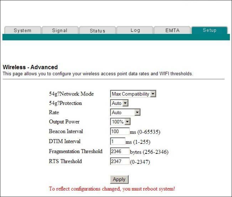
4011350 Rev A 119
How Do I Configure the Wireless Home Gatewa
y
?
Setup Wireless - Advanced Page Example
The following illustration is an example of the Setup Wireless - Advanced page.
Note: We recommend that you do not change the default wireless settings that are
shown in the preceding illustration unless you are instructed to do so by your cable
service provider.
Setup Wireless - Advanced Page Description
This section describes the section headings and fields descriptions of the Setup
Wireless - Advanced page.
Note: If you make changes in the Setup Wireless - Advanced page, click Apply to
apply and save your wireless advanced settings.

120 4011350 Rev A
How Do I Configure the Wireless Home Gateway?
Field Name Description
54g Network Mode Allows you to optimize the performance of your
wireless network using one of the following options:
Max compatibility (factory default)
Allows the access point to interoperate with
both 802.11b and 802.11g wireless client
devices and minimizes interference with
nearby 802.11b wireless networks.
54g Only
The wireless access point will only accept
802.11g wireless clients.
Max Performance
Maximum throughput. In this mode, the
wireless access point accepts only 802.11g
wireless clients. Setting the device in this
mode may degrade the operation of near by
802.11b wireless networks.
54g Protection Allows you to prioritize 802.11g communication when
there is a mix of 802.11b and 802.11g devices in the
wireless network using one of the following options:
Auto (factory default)
Maximize 802.11g performance in networks
with a mix of 802.11b and 802.11g wireless
client devices.
Off
Maximum performance. Networks with
802.11g-only wireless client devices.
Rate Allows you to fix the data rate for wireless connections.
The following data rates are available:
Auto (factory default), 1 Mbps, 2 Mbps, 5.5 Mbps,
6 Mbps, 9 Mbps, 11 Mbps, 12 Mbps, 18 Mbps,
24 Mbps, 36 Mbps, 48 Mbps, 54 Mbps
Note: In the automatic mode, data rate is a function of
signal strength and signal quality.
Output Power Allows you to adjust the relative output power of your
gateway wireless transmitter. The following settings
are available:
100% (factory default), 75%, 50%, and 25%

4011350 Rev A 121
How Do I Configure the Wireless Home Gatewa
y
?
Field Name Description
Beacon Interval Displays the time interval that the WAP uses to
announce itself to remote devices. The Beacon Interval
should be left at 100ms for compliance with most client
cards. The Beacon Interval specifies how often packets
are sent by the Access Point (AP) to synchronize a
wireless network and its clients
DTIM Interval Displays the time interval between
Broadcasts/Multicast transmissions. The DTIM
(Delivery Traffic Indication Message) Interval is a
countdown informing the wireless clients of the next
window for listening to broadcast and multicast
messages. When the AP has buffered broadcast or
multicast messages for associated clients, it sends the
next DTIM with a DTIM Interval value. AP clients hear
the beacons and awaken to receive the broadcast and
multicast messages. The DTIM Interval should be left
at 3 ms for compliance with most client cards
Fragmentation
Threshold
Allows you to set the fragmentation threshold. This
threshold should be set equivalent to the maximum
Ethernet frame size allowable on the link including
overhead (1536 bytes). Lesser settings can damage data
throughput as large frames could be fragmented or
collisions could occur. The factory default is 2346
RTS Threshold Determines at what packet size beyond which the
ready to send/clear to send (RTS/CTS) mechanism is
invoked. The factory default is 2347
Configuring Wireless Access Point Access Control
Use the Setup Wireless - Access Control page to configure your configure your
wireless access point access control.
Note: If you are not familiar with the advanced settings detailed in this section,
contact your cable service provider before you attempt to change any of the wireless
home gateway default wireless advanced settings.
Click Access Control in the Wireless section of the Setup page to access the Setup
Wireless - Access Control page.
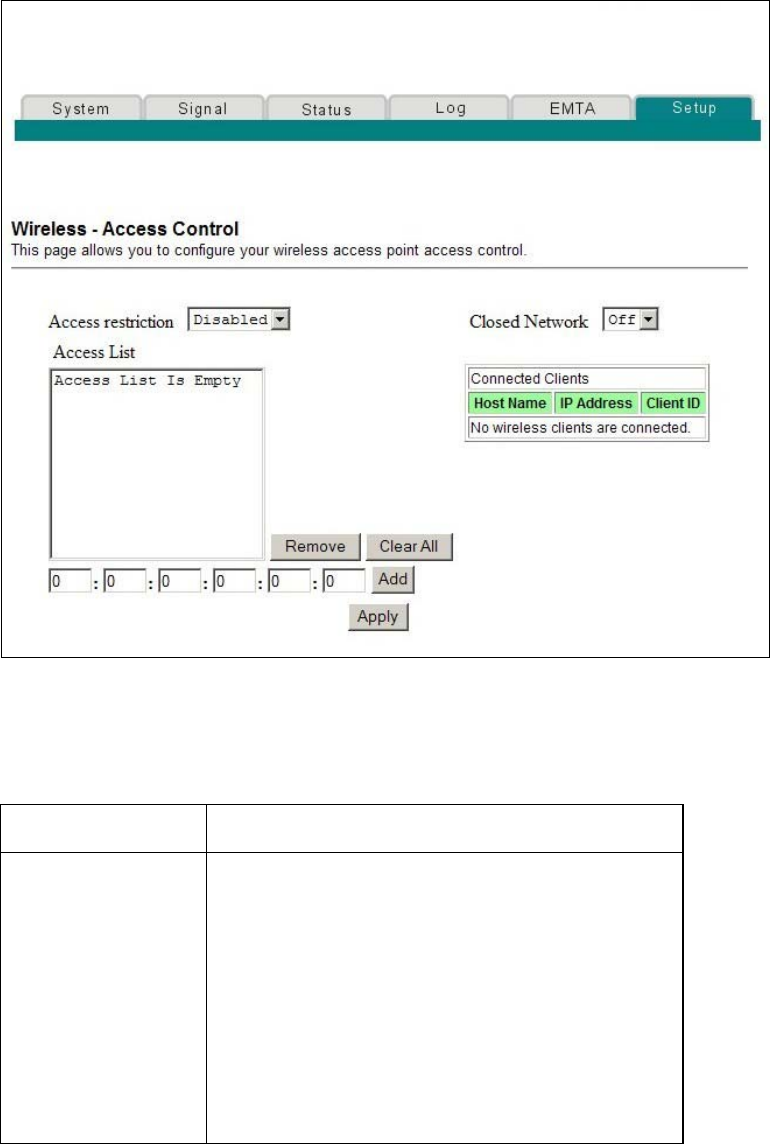
122 4011350 Rev A
How Do I Configure the Wireless Home Gateway?
Setup Wireless Access Control Page Example
Setup Wireless - Access Control Page Description
This section describes the section headings and field descriptions of the Setup
Wireless - Access Control page.
Field Name Description
Access restriction When encryption is enabled, this selection allows
you to choose one of the following options from the
drop-down list:
Disable (factory default)–No access restrictions
based on MAC address of wireless access
devices
Allow–Allows wireless access to only the MAC
addresses listed in the Access List
Deny–Denies wireless access to only the MAC
address listed in the Access List

4011350 Rev A 123
How Do I Configure the Wireless Home Gatewa
y
?
Field Name Description
Closed Network Allows you to disable or enable the network to
access by wireless clients. When ON is selected, the
access point does not broadcast the SSID. The client
device must be configured manually with the SSID
and the MAC address of the access point in order to
access with wireless network.
Access List Displays the MAC address of the clients that are
subject to wireless access control
Connected Clients Displays the Host Name, IP Address, and Client ID
of wireless clients that are connected to (associated
with) the gateway modem
Function Keys
The following function keys appear on the Setup Firewall - Event Logging page.
Key Description
Apply Applies and saves the values you enter into the
fields without closing the screen
Clear All Clears the Access List
Remove Removes entries from the Access List
Add Adds a client to the Access List using the MAC
address of the client
124 4011350 Rev A
Telephone Service Frequently Asked Questions
Telephone Service Frequently Asked Questions
This section provides answers to frequently asked questions regarding wireless
home gateway telephone service. For issues regarding wireless home gateway
Internet service, see How Do I Troubleshoot My Internet Service Installation?
(on page 35)
Frequently Asked Questions
Q. What if I don't subscribe to telephone service from my cable operator, can I
still use the wireless home gateway to make and receive phone calls?
A. No. Telephone service is enabled for each telephone port on the wireless home
gateway by the cable telephony service provider. Contact your cable telephony
service provider to get telephone service through the wireless home gateway.
Q. How do I arrange for installation?
A. Professional installation from your cable telephony service provider may be
provided. A professional installer can connect the telephone service to your existing
telephone wiring in your home or install new wiring if needed. Professional
installation also ensures proper cable connection to the modem and to your PC, and
ensures proper configuration of all hardware and software settings. Contact your
cable telephony service provider for more information about installation.
Q. Can I use my existing phone number with the wireless home gateway?
A. Telephone numbers are portable in some areas. Contact your telephone service
provider for more information about using an existing telephone number.
Q. Do I automatically receive high-speed Internet service with the wireless home
gateway?
A. Your wireless home gateway may be used to provide telephone service, high-
speed Internet service, or both services. Your cable service provider enables Internet
service. Contact your cable service provider for more information if you are not
currently subscribing to Internet service.
Q. How many telephones can I connect?
A. The RJ-11 telephone-style connectors on the wireless home gateway can each
provide telephone service to multiple telephones, fax machines, and analog
modems. The maximum number of telephone devices connected to each RJ-11 port
is limited by the total Ringing Load of the telephone devices that are connected.
Many telephone devices are marked with a Ringer Equivalent Number (REN). Each
telephone port on the wireless home gateway can support up to a 5 REN load. The
sum of the REN load on all of the telephone devices attached to each port must not
exceed 5 REN.
4011350 Rev A 125
Telephone Service Frequently Asked Questions
Q. Can I surf the Internet and make telephone calls at the same time?
A. Absolutely! Telephone service is provided separately from Internet data services.
Internet surfing and other data services do not affect the quality of your telephone
calls. If these services are enabled by your cable service provider, you can make
telephone calls and surf the net at the same time.
126 4011350 Rev A
Having Difficulty?
Having Difficulty?
Common Troubleshooting Suggestions
The modem does not register a cable connection
The modem works with a standard, 75-ohm, RF coaxial cable. If you are using a
different cable, your wireless home gateway will not function properly. Contact your
service provider to determine whether you are using the correct cable.
There is no dial tone when I lift the telephone handset
Your telephone wiring may be connected to the wrong RJ-11 port on the wireless
home gateway. The wireless home gateway has two telephone ports. Verify that
you are connected to the correct telephone port.
There may be a problem with your telephone set. Use a different telephone set
and listen to hear dial tone.
There may be a problem with your home telephone wiring. Use a telephone and
connect directly to the same RJ-11 port on the back of the unit. If the dial tone is
working here but does not work at other locations in the home, a professional
may need to diagnose and repair a problem with your telephone wiring.
Verify that the phone company has removed the previous telephone service from
your home telephone wiring.
Your telephone service may not be enabled from your cable telephony service
provider. Contact your cable telephony service provider for more information.
Frequently Asked Questions
Q. What if I don't subscribe to cable TV?
A. If cable TV is available in your area, data service may be made available with or
without subscribing to cable TV service. Contact your local cable service provider for
complete information on cable services, including high-speed Internet access.
Q. How do I arrange for installation?
A. Call your cable telephony service provider to inquire about professional
installation. A professional installation ensures proper cable connection to the
modem and to your PC, and it ensures the proper configuration of all hardware and
software settings. Contact your cable telephony service provider for more
information about installation.
4011350 Rev A 127
Having Difficult
y
?
Q. How does the wireless home gateway connect to my computer?
A. The wireless home gateway connects to the USB port or the 10/100BaseT
Ethernet port on your PC. If your PC is not equipped with an Ethernet interface, an
Ethernet card is available from your local PC or office supply retailer, or from your
cable service provider.
Q. After my wireless home gateway is connected, how do I access the Internet?
A. Your local service provider becomes your Internet Service Provider (ISP). They
offer a wide range of services including e-mail, chat, news, and information services.
Your cable service provider will provide the software you will need.
Q. Can I watch TV and surf the Internet at the same time?
A. Absolutely! If you subscribe to cable television service, you can watch TV and
use your wireless home gateway at the same time by connecting your TV and your
wireless home gateway to the cable network using an optional cable signal splitter.
Q. Can I run more than one device on the modem?
A. Yes. A single wireless home gateway will theoretically support up to 253
Ethernet devices utilizing user-supplied Ethernet hubs or routers that you can
purchase at your local PC or office supply retailer. Another user at your location can
simultaneously connect to the USB port on the wireless home gateway. Contact your
service provider for further assistance.
Common Troubleshooting Issues
I don't understand the front panel status indicators
See Front Panel LED Status Indicator Functions (on page 130), for more detailed
information on front panel LED status indicator operation and function.
The modem does not register an Ethernet connection
Verify that your computer has an Ethernet card and that the Ethernet driver
software is properly installed. If you purchase and install an Ethernet card,
follow the installation instructions very carefully.
Verify the status of the front panel status indicator lights.
The modem does not register an Ethernet connection after connecting to a hub
If you are connecting multiple PCs to the wireless home gateway, you should first
connect the modem to the uplink port of the hub using the correct crossover cable.
The LINK LED of the hub will illuminate continuously.
128 4011350 Rev A
Having Difficulty?
The modem does not register a cable connection
The modem works with a standard 75-ohm RF coaxial cable. If you are using a
different cable, your wireless home gateway will not function properly. Contact
your cable service provider to determine whether you are using the correct cable.
Verify that you have followed the procedures in How Do I Troubleshoot My
Internet Service Installation? (on page 35).
Your NIC card or USB interface may be malfunctioning. Refer to the
troubleshooting information in the NIC or USB documentation provided with
the device.
4011350 Rev A 129
Tips for Improved Performance
Tips for Improved Performance
Check and Correct
If your wireless home gateway does not perform as expected, the following tips may
help. If you need further assistance, contact your service provider.
Verify that the plug to your wireless home gateway AC power is properly
inserted into an electrical outlet.
Verify that your wireless home gateway AC power cord is not plugged into an
electrical outlet that is controlled by a wall switch. If a wall switch controls the
electrical outlet, make sure the switch is in the ON position.
Verify that the POWER and ONLINE LED status indicators on the front panel of
your wireless home gateway are illuminated.
Verify that all cables are properly connected, and that you are using the correct
cables.
Verify that your cable service is active and that it supports two-way service.
Verify that your TCP/IP is properly installed and configured if you are using the
Ethernet connection.
Verify that you have followed the procedures in How Do I Install USB Drivers?
(on page 25), if you are using the USB connection.
Verify that you have called your service provider and given them the serial
number and MAC address of your wireless home gateway.
If you are using a cable signal splitter so that you can connect the wireless home
gateway to other devices, remove the splitter and reconnect the cables so that the
wireless home gateway is connected directly to the cable input. If the wireless
home gateway now functions properly, the cable signal splitter may be defective
and may need to be replaced.
For best performance over an Ethernet connection, your PC should be equipped
with a 10/100BaseT network interface card.

130 4011350 Rev A
Front Panel LED Status Indicator Functions
Front Panel LED Status Indicator Functions
Initial Power Up, Calibration, and Registration (AC Power applied)
The following chart illustrates the sequence of steps and the corresponding
appearance of the wireless home gateway front panel LED status indicators during
power up, calibration, and registration on the network when AC power is applied to
the wireless home gateway. Use this chart to troubleshoot the power up, calibration,
and registration process of your wireless home gateway.
Note: After the wireless home gateway completes Step 7 (Registration Completed),
the modem proceeds immediately to Normal Operations. See Normal Operations
(AC Power applied) (on page 131).
Front Panel LED Status Indicators During Initial Power Up, Calibration, and Registration
Step1234567
Front Panel
Indicator
Self
Test
Downstream
Scan
Downstream
Signal Lock
Ranging Requesting
IP Address
Registering Registration
Completed
1 POWER ON ON ON ON ON ON ON
2 DS ON BLINKING ON ON ON ON ON
3 US ON OFF OFF BLINKING ON ON ON
4 ONLINE ON OFF OFF OFF OFF BLINKING ON
5 LAN1
through
LAN4/USB
ON ON
or
BLINKING
ON
or
BLINKING
ON
or
BLINKING
ON
or
BLINKING
ON
or
BLINKING
ON
or
BLINKING
6 WIRELESS ON ON
or
BLINKING
ON
or
BLINKING
ON
or
BLINKING
ON
or
BLINKING
ON
or
BLINKING
7 TEL1 ON OFF OFF OFF OFF OFF OFF
8 TEL2 ON OFF OFF OFF OFF OFF OFF
9 BATTERY OFF OFF OFF OFF OFF OFF OFF
*The ONLINE LED is on whenever a PC is connected to the modem, and it blinks to indicate that data is being
transferred. If the modem is used to provide telephone service only and is not connected to a PC, the ONLINE
LED is off.

4011350 Rev A 131
Front Panel LED Status Indicator Functions
Normal Operations (AC Power applied)
The following chart illustrates the appearance of the wireless home gateway front
panel LED status indicators during normal operations when AC power is applied to
the gateway.
Step 8
Front Panel LED Status Indicators During Normal Operations
Front Panel
Indicator
Normal Operations
1 POWER ON
2 DS BLINKS - To indicate data is being transferred between the modem
and the network
3 US BLINKS - To indicate data is being transferred between the modem
and the network
4 ONLINE ON
5 LAN 1
through LAN
4/USB
ON - When a single device is connected to either the Ethernet or USB
port and no data is being sent to or from the modem
BLINKS - When only one Ethernet or USB device is connected and
data is being transferred between the consumer premise equipment
(CPE) and the wireless home gateway
OFF - When no devices are connected to either the Ethernet or USB
ports
NOTE: With both Ethernet and USB devices connected to the modem
at the same time, when data is being transferred through only one of
the devices (Ethernet or USB), the indicator will illuminate
continuously. Whenever data is being sent through both data ports
(Ethernet and USB) simultaneously, the indicator will blink as
described above.
6 WIRELESS ON when the wireless access point is enabled and operational
BLINKS when data is being transferred between the CPE and the
wireless home gateway
OFF when the wireless access point is disabled by the user
7 TEL1 ON when telephony service is enabled
BLINKS when line 1 is in use
8 TEL2 ON when telephony service is enabled
BLINKS when line 2 is in use
9 BATTERY ON when battery is charged
BLINKS when battery charge is low
OFF when there is no battery in the unit

132 4011350 Rev A
Front Panel LED Status Indicator Functions
Special Conditions
The following chart describes the appearance of the cable modem front panel LED
status indicators during special conditions to show when you have been denied
network access or when the modem is operating on battery power.
Front Panel LED Status Indicators During Special Conditions
Front Panel
Indicator
Network Access
Denied
Operating on Battery Power
1 POWER Slow Blinking
1 time per second
Slow Blinking
1 time per second
2 DS Slow Blinking
1 time per second
Off
3 US Slow Blinking
1 time per second
Off
4 ONLINE Slow Blinking
1 time per second
Slow Blinking
1 time per second
5 LAN 1 through
LAN 4
Slow Blinking
1 time per second
Off
6 WIRELESS On Off
7 TEL1 Off Off
8 TEL2 Off Off
9 BATTERY On Off
4011350 Rev A 133
Notices
Notices
Trademarks
Scientific Atlanta is a registered trademark of Scientific-Atlanta, Inc.
DPC2434 is a trademark of Scientific-Atlanta, Inc.
Cisco, Cisco Systems, and the Cisco Systems logo are registered trademarks of Cisco
Systems, Inc. and/or its affiliates in the U.S. an d certain other countries.
DOCSIS is a registered trademarks of Cable Television Laboratories, Inc.
PacketCable is a trademark of Cable Television Laboratories, Inc.
Other trademarks listed herein are the property of their respective owners.
Disclaimer
Scientific-Atlanta, Inc. assumes no responsibility for errors or omissions that may
appear in this guide. Scientific-Atlanta, Inc. reserves the right to change this guide at
any time without notice.
Documentation Copyright Notice
© 2006 Scientific-Atlanta, Inc. All rights reserved.
Printed in the United States of America.
Information in this document is subject to change without notice. No part of this
document may be reproduced in any form without the express written permission of
Scientific-Atlanta, Inc.
Software Use Notice
The software described in this document is copyrighted and furnished to you under
a license agreement. You may only use or copy this software in accordance with the
terms of your license agreement.
Firmware Use Notice
The firmware in this equipment is copyrighted. You may only use the firmware in
the equipment in which it is provided. Any reproduction or distribution of this
firmware, or any portion of it, without express written consent is prohibited.
134 4011350 Rev A
Notices
FCC Radiation Exposure Statement
This equipment complies with FCC radiation exposure limits set forth for an
uncontrolled environment. To maintain compliance with the FCC RF exposure
guidelines, this equipment should be installed and operated with minimum distance
of at least 7.8 in. (20cm) from all persons.
4011350 Rev A 135
For Information
For Information
If You Have Questions
If you have technical questions, contact your local cable service provider.

Scientific-Atlanta, A Cisco Company
5030 Sugarloaf Parkway, P.O. Box 465477
Lawrenceville, GA 30042
770.236.5000
www.scientificatlanta.com
Product and service availability subject to change without notice.
© 2006 Scientific-Atlanta, Inc. All rights reserved.
Printed in United States of America
August 2006 Part Number 4011350 Rev A