ASUSTeK Computer EW2000TX ASUS WICAST User Manual
ASUSTeK Computer Inc ASUS WICAST Users Manual
Users Manual

User Manual
Model
No.:EW2000
Model
name:
WHDI
transmitter
module
V
ersion:
v0.1
Date:
July-12,
2010
2
Federal Communication Commission Interference Statement
This equipment has been tested and found to comply with the limits for a Class B digital device, pursuant to
Part 15 of the FCC Rules. These limits are designed to provide reasonable protection against harmful
interference in a residential installation. This equipment generates, uses and can radiate radio frequency
energy and, if not installed and used in accordance with the instructions, may cause harmful interference to
radio communications. However, there is no guarantee that interference will not occur in a particular
installation. If this equipment does cause harmful interference to radio or television reception, which can
be determined by turning the equipment off and on, the user is encouraged to try to correct the interference
by one of the following measures:
z Reorient or relocate the receiving antenna.
z Increase the separation between the equipment and receiver.
z Connect the equipment into an outlet on a circuit different from that to which the receiver is
connected.
z Consult the dealer or an experienced radio/TV technician for help.
Any changes or modifications not expressly approved by the party responsible for compliance could void
the user's authority to operate this equipment.
This device is restricted to indoor use when operated in the 5.15 to 5.25 GHz frequency range.
FCC / IC Radiation Exposure Statement:
This equipment complies with FCC/ IC RSS-102 radiation exposure limits set
forth for an uncontrolled environment. This equipment should be installed and
operated with minimum distance 20cm between the radiator & your body.
This module is intended for OEM integrator only and limited to host with ASUS
WiCast model: EW2000; EW2000TX. The OEM integrator is still responsible for
the FCC compliance requirement of the end product, which integrates this
module.
20cm minimum distance has to be able to be maintained between the antenna
and the users for the host this module is integrated into. Under such
configuration, the FCC radiation exposure limits set forth for an
population/uncontrolled environment can be satisfied.
Any changes or modifications not expressly approved by the manufacturer could
void the user's authority to operate this equipment.
The FCC part 15.19 statement below has to also be available in the
manual: This device complies with Part 15 of FCC rules.
Operation is subject to the following two conditions: (1) this device may not
cause harmful interference and (2) this device must accept any interference
received, including interference that may cause undesired operation.
To reduce potential radio interference to other users, the antenna type and its
gain should be so chosen that the equivalent isotropically radiated power (EIRP)
is not more than that required for successful communication.
This device has been designed to operate with an antenna having a maximum
gain of [2.11] dBi. Antenna having a higher gain is strictly prohibited per
regulations of Industry Canada. The required antenna impedance is 50 ohms.
To reduce potential radio interference to other users, the antenna type and its
gain should be so chosen that the equivalent isotropically radiated power (e.i.r.p.)
is not more than that permitted for successful communication.
3
This Class [B] digital apparatus complies with Canadian ICES-003.
Cet appareil numérique de la classe [B] est conforme à la norme NMB-003 du
Canada.
Contents
1. Revision History ................................................................................................... 3
2. Related Documents .............................................................................................. 3
3. Overview ............................................................................................................... 4
3.1. Scope .......................................................................................................... 4
3.2. Features ...................................................................................................... 4
3.3. Specification .............................................................................................. 5
3.4. Mechanical Characteristics ........................................................................ 6
3.5. Module function Block Diagram ............................................................... 7
3.6. RoHS Compliant ........................................................................................ 7
3.7. EMI EMC certifications............................................................................. 7
4. Engineering sheets ............................................................................................... 8
4
3. Overview
3.1. Scope
The EW2000 wireless transmitter module, together with the EW2000
wireless receiver module, presents the ultimate solution for converting
any High Definition (HD) system into a wireless one. This add-on module
enables wireless A/V applications that easily fit into the living room and
eliminate traditional A/V wiring. The ultimate HD video and audio quality
and robustness are unmatched by any other wireless technology, and
present a true alternative to cable.
3.2. Features
Transmission technology
z MIMO
Cable Free
z To eliminate the wires clutter from the living room
Video resolutions
z Up to 1080p
Frequencies supported
z Unlicensed 5GHz band
Range
z At least 5m in room
z Line-of-sight will depend on the environment
Application Bandwidth
z The Control Channel allows two-way communication of
100Kbps
Latency
z Less than 1ms delay between video/audio source and sink.

5
3.3. Specification
Interface
Digital Video:30-bit RGB or YCrCb
Digital
a
udio:
I2S
and
SPDIF
Two-W
i
r
e
serial
bus
sl
a
v
e
in
te
rf
ace
One
interrup
t
line
Network
S
tandard
5GHz
unlicensed
band
Modulation
OFDM
T
echnique
Proprietary
Operating Frequenc
y
5.18
G
Hz to 5.875
G
Hz
Operating Channels
USA/Canada: 36/40/44/48/149/153/157/161/165
Japan: 36/40/44/48
EU/AUS/NZ: 36/40/44/48
RF Output Power
TBD
Antenna
With
2
ex
te
rna
l
antennas
Supply
V
oltage
5V±10%
Power Consumption
3.5W max
6
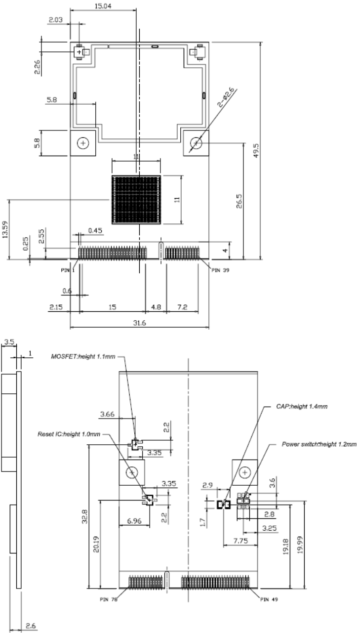
3.4. Mechanical Characteristics
7
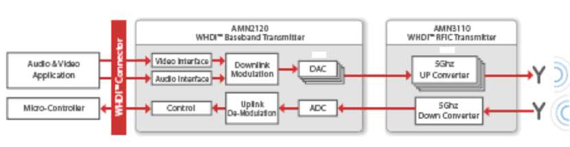
3.5. Module function Block Diagram
3.6. RoHS Compliant
HM510 is fully compliant to RoHS requirement.
3.7. EMI EMC certifications
HM510 is fully compliant with FCC regulatory requirements.

8
4. Engineering sheets
Pins Out and Pin Descriptions :
1 GND 40 GND
2 5V 41 5V
3 5V 42 5V
4 GND 43 GND
5 WHDI_DCLK 44 WHDI_H_SYNC
6 GND 45 WHDI_V_SYNC
7 WHDI_DE 46 GND
8 WHDI_D34 47 WHDI_D35
9 WHDI_D32 48 WHDI_D33
10 WHDI_D30 49 WHDI_D31
11 WHDI_D28 50 WHDI_D29
12 WHDI_D26 51 WHDI_D27
13 GND 52 GND
14 WHDI_D22 53 WHDI_D23
15 WHDI_D20 54 WHDI_D21
16 WHDI_D18 55 WHDI_D19
17 WHDI_D16 56 WHDI_D17
18 WHDI_APP_DEBUG1_D14 57 WHDI_APP_DEBUG2_D15
19 GND 58 GND
20 WHDI_D10 59 WHDI_D11
21 WHDI_D8 60 WHDI_D9
22 WHDI_D6 61 WHDI_D7
23 WHDI_D4 62 WHDI_D5
24 WHDI_D2 63 WHDI_D3
25 GND 64 GND
26 WHDI_MCLK 65 WHDI_I2S_D3
27 WHDI_SCLK 66 WHDI_I2S_D2
28 WHDI_LRCLK 67 WHDI_I2S_D1
29 WHDI_SPDIF 68 WHDI_I2S_D0
30 GND 69 WHDI_HPD
31 WHDI_USB_D- 70 WHDI_I2CS_SCL
32 WHDI_USB_D+ 71 WHDI_I2CS_SDA
33 GND 72 WHDI_TXD_APP
34 WHDI_M_SCL 73 WHDI_RXD_APP

9
WHDI_M_SDA 74 WHDI_RESET_IN
36 WHDI_INT_OUT_PE 75 WHDI_HDMI_RESET_OUT
37 WHDI_HDMI_INT_IN 76 WHDI_GPIO0
38 WHDI_PWM0 77 WHDI_GPIO1
39 WHDI_PWM1 78 WHDI_GPIO2
35