ASUSTeK Computer F9F Notebook P.C. User Manual T13Fg UserMan
ASUSTeK Computer Inc Notebook P.C. T13Fg UserMan
Manual
Notebook PC
Hardware User’s Manual
ASUS WIDE SCREEN NOTEBOOK
OFFON
E2896 / Oct 2006

2
Contents
Table of Contents
1. Introducing the Notebook PC
About This User’s Manual .......................................................................................... 6
Notes For This Manual........................................................................................... 6
Preparing your Notebook PC...................................................................................... 9
2. Knowing the Parts
Top Side.................................................................................................................... 12
Bottom Side.............................................................................................................. 14
Left Side ................................................................................................................... 16
Right Side................................................................................................................. 18
Rear Side.................................................................................................................. 20
Front Side................................................................................................................. 21
3. Getting Started
Power System .......................................................................................................... 24
Using AC Power................................................................................................... 24
Using Battery Power ............................................................................................ 25
Battery Care......................................................................................................... 25
Powering ON the Notebook PC ........................................................................... 26
The Power-On Self Test (POST).......................................................................... 26
Checking Battery Power ...................................................................................... 27
Charging the Battery Pack................................................................................... 27
Restarting or Rebooting....................................................................................... 28
Powering OFF...................................................................................................... 28
Special Keyboard Functions..................................................................................... 29
Colored Hot Keys................................................................................................. 29
Microsoft Windows Keys...................................................................................... 31
Keyboard as a Numeric Keypad ......................................................................... 31
Keyboard as Cursors ........................................................................................... 31
Switches and Status Indicators ................................................................................ 32
Switches............................................................................................................... 32
Status Indicators .................................................................................................. 33
Table of Contents

3
Contents
4. Using the Notebook PC
Operating System..................................................................................................... 36
Support Software ................................................................................................. 36
Automatic Touchpad Disabling (on selected models) ......................................... 36
Pointing Device......................................................................................................... 37
Using the Touchpad ............................................................................................. 37
Touchpad Usage Illustrations............................................................................... 38
Caring for the Touchpad....................................................................................... 39
Storage Devices ....................................................................................................... 40
Expansion Card ................................................................................................... 40
Optical Drive ........................................................................................................ 41
Flash Memory Card Reader ................................................................................ 43
Hard Disk Drive.................................................................................................... 43
Connections.............................................................................................................. 44
Modem Connection.............................................................................................. 44
Network Connection ............................................................................................ 45
Wireless LAN Connection (on selected models) ................................................. 46
Bluetooth Wireless Connection (on selected models) ......................................... 47
Power Management Modes...................................................................................... 48
Full Power Mode & Maximum Performance ........................................................ 48
ACPI..................................................................................................................... 48
Suspend Mode..................................................................................................... 48
Power Savings..................................................................................................... 48
Power State Summary......................................................................................... 49
Thermal Power Control........................................................................................ 49
Stand by and Hibernate ....................................................................................... 50
Appendix
Optional Accessories................................................................................................ 52
Glossary ................................................................................................................... 54
Declarations and Safety Statements ........................................................................ 58
Notebook PC Information ......................................................................................... 68

4
Contents

5
1. Introducing the Notebook PC
About This User’s Manual
Notes For This Manual
Safety Precautions
Preparing your Notebook PC

6
1 Introducing the Notebook PC
About This User’s Manual
You are reading the Notebook PC User’s Manual. This User’s Manual provides informa-
tion on the various components in the Notebook PC and how to use them. The following
are major sections of this User’s Manuals:
1. Introducing the Notebook PC
Introduces you to the Notebook PC and this User’s Manual.
2. Knowing the Parts
Gives you information on the Notebook PC’s components.
3. Getting Started
Gives you information on getting started with the Notebook PC.
4. Using the Notebook PC
Gives you information on using the Notebook PC’s components.
5. Appendix
Introduces you to optional accessories and gives additional information.
Notes For This Manual
A few notes and warnings in bold are used throughout this guide that you should be aware of in order
to complete certain tasks safely and completely. These notes have different degrees of importance as
described below:
NOTE: Tips and information for special situations.
TIP: Tips and useful information for completing tasks.
IMPORTANT! Vital information that must be followed to prevent damage to data, com-
ponents, or persons.
WARNING! Important information that must be followed for safe operation.
Text enclosed in < > or [ ] represents a key on the keyboard; do not actually type the
< > or [ ] and the enclosed letters.
< >
[ ]
7
Introducing the Notebook PC 1
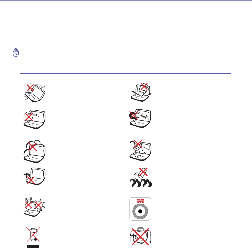
Safety Precautions
The following safety precautions will increase the life of the Notebook PC. Follow all precautions and
LQVWUXFWLRQV([FHSWDVGHVFULEHGLQWKLVPDQXDOUHIHUDOOVHUYLFLQJWRTXDOLÀHGSHUVRQQHO'RQRWXVH
GDPDJHGSRZHUFRUGVDFFHVVRULHVRURWKHUSHULSKHUDOV'RQRWXVHVWURQJVROYHQWVVXFKDVWKLQQHUV
benzene, or other chemicals on or near the surface.
IMPORTANT! Disconnect the AC power and remove the battery pack(s) before clean-
ing. Wipe the Notebook PC using a clean cellulose sponge or chamois cloth dampened
with a solution of nonabrasive detergent and a few drops of warm water and remove
any extra moisture with a dry cloth.
DO NOT expose to or use near liquids,
rain, or moisture. DO NOT use the
modem during an electrical storm.
DO NOT expose to dirty or dusty en-
vironments. DO NOT operate during
a gas leak.
SAFE TEMP: This Notebook PC
should only be used in environments
with ambient temperatures between
5°C (41°F) and 35°C (95°F)
Battery safety warning:
DO NOT WKURZWKHEDWWHU\LQÀUH
DO NOT short circuit the contacts.
DO NOT disassemble the battery.
DO NOT expose to strong magnetic
RUHOHFWULFDOÀHOGV
DO NOT place on uneven or unstable
work surfaces. Seek servicing if the
casing has been damaged.
DO NOT place or drop objects on top
and do not shove any foreign objects
into the Notebook PC.
DO NOT press or touch the display
SDQHO 'R QRW SODFH WRJHWKHU ZLWK
small items that may scratch or enter
the Notebook PC.
DO NOT leave the Notebook PC on
your lap or any part of the body in
order to prevent discomfort or injury
from heat exposure.
DO NOT throw the Notebook PC
in municipal waste. Check local
regulations for disposal of electronic
products.
DO NOT carry or cover a Notebook
PC that is powered ON with any ma-
terials that will reduce air circulation
such as a carrying bag.
INPUT RATING: Refer to the rating
label on the bottom of the Notebook
PC and be sure that your power adapter
complies with the rating.

8
1 Introducing the Notebook PC
CAUTION! There are three main types of airport security devices: X-ray machines
(used on items placed on conveyor belts), magnetic detectors (used on people walking
through security checks), and magnetic wands (hand-held devices used on people or
individual items). You can send your Notebook PC and diskettes through airport X-ray
machines. However, it is recommended that you do not send your Notebook PC or
diskettes through airport magnetic detectors or expose them to magnetic wands.
Charge Your Batteries
If you intend to use battery power, be sure to fully charge your battery pack and any optional battery
packs before going on long trips. Remember that the power adapter charges the battery pack as long as
it is plugged into the computer and an AC power source. Be aware that it takes much longer to charge
the battery pack when the Notebook PC is in use.
Airplane Precautions
Contact your airline if you want to use the Notebook PC on the airplane. Most airlines will have restric-
tions for using electronic devices. Most airlines will allow electronic use only between and not during
takeoffs and landings.
Transportation Precautions
To prepare the Notebook PC for transport, you should turn it OFF and disconnect all external peripher-
als to prevent damage to the connectors. The hard disk drive’s head retracts when the power is turned
OFF to prevent scratching of the hard disk surface during transport. Therefore, you should not transport
the Notebook PC while the power is still ON. Close the display panel and check that it is latched securely
in the closed position to protect the keyboard and display panel.
CAUTION: The Notebook PC’s surface is easily dulled if not properly cared for. Be
careful not to rub or scrape the Notebook PC surfaces.
Cover Your Notebook PC
Purchase a carrying bag to protect the Notebook PC from dirt, water, shock, and scratches.
9
Introducing the Notebook PC 1
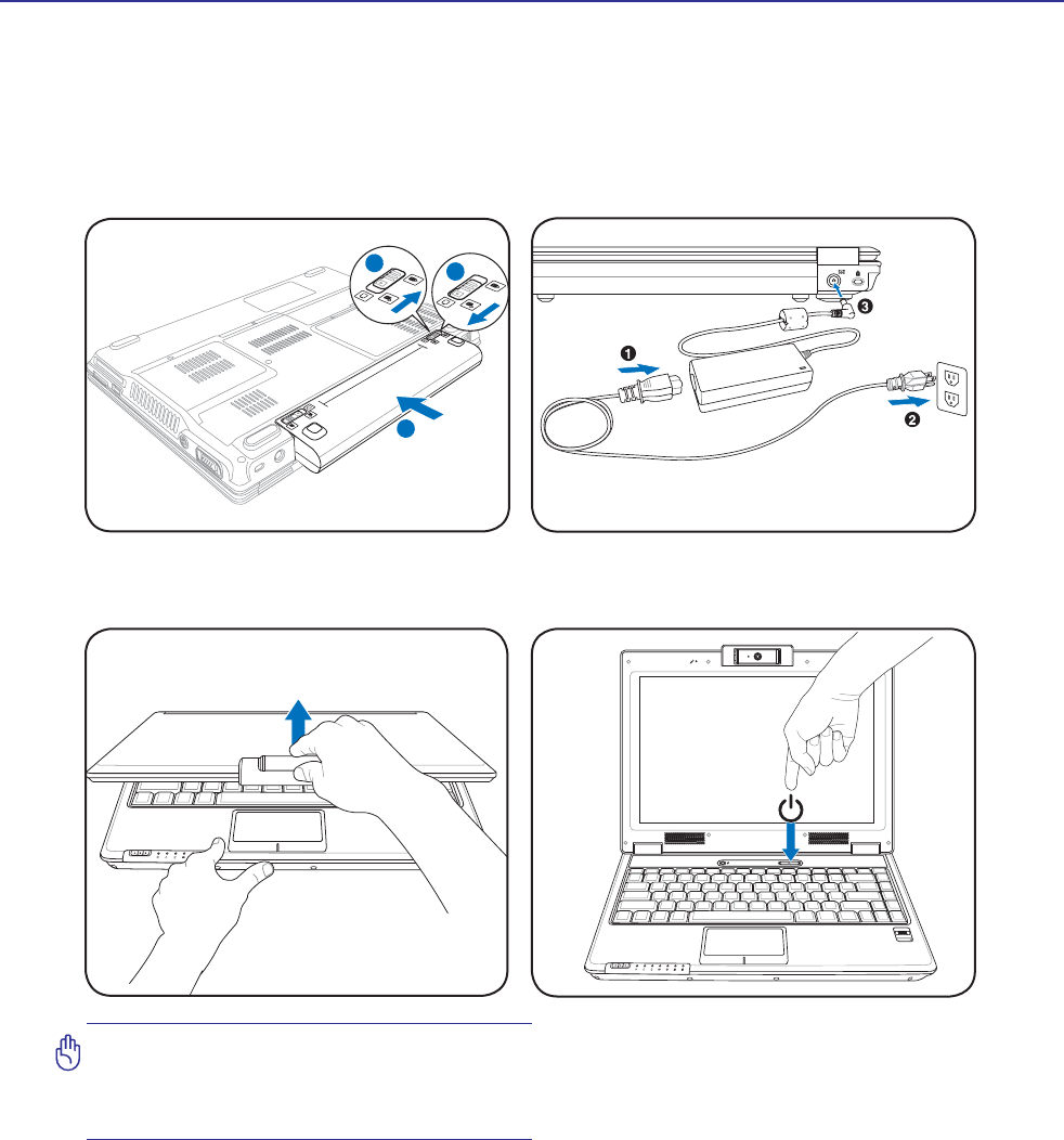
Preparing your Notebook PC
These are only quick instructions for using your Notebook PC. Read the later pages for detailed informa-
tion on using your Notebook PC.
1. Install the battery pack 2. Connect the AC Power Adapter
Press the power button and release.
(In Windows XP, this button can also be used to
safely turn OFF the Notebook PC.)
IMPORTANT! When opening, do not force
the display panel down to the table or else
the hinges may break! Never lift the Note-
book PC by the display panel!
OFF ON
ASUS WIDE SCREEN NOTEBOOK
2
31
1.3
MEGA
PIXELS
OFF ON
ASUS WIDE SCREEN NOTEBOOK
3. Open the Display Panel 4. Turn ON the Notebook PC

10
1 Introducing the Notebook PC

11
2. Knowing the Parts
Basic sides of the Notebook PC
NOTE: Photos and icons in this manual are used for artistic purposes only and do not
show what is actually used in the product itself.
12
2 Knowing the Parts
1
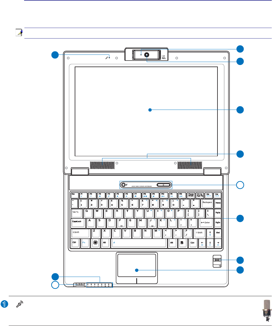
Top Side
Refer to the diagram below to identify the components on this side of the Notebook PC.
NOTE: The keyboard will be different for each territory.
4
5
7
8
3
1
2
10
9
6
6
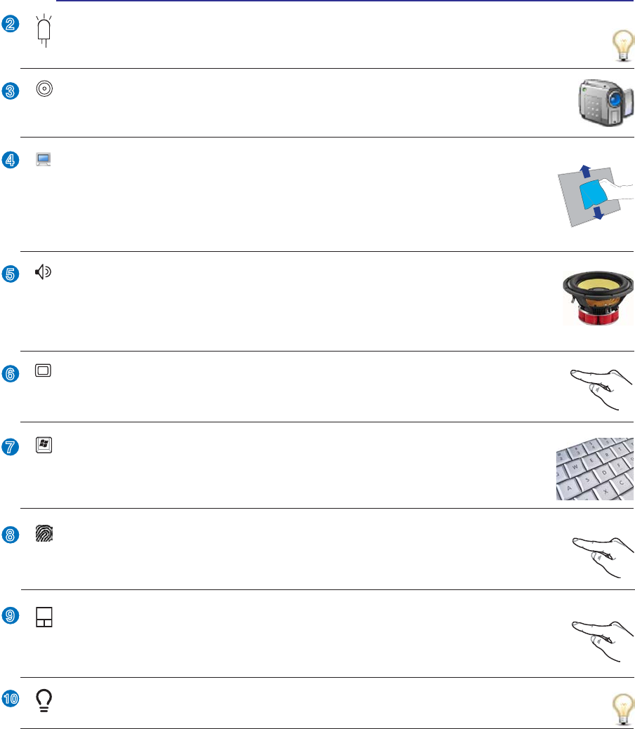
Microphone (Built-in)
The built-in mono microphone can be used for video conferencing, voice narrations, or simple
audio recordings.
(continued on next page)
13
Knowing the Parts 2
2
3
4
5
6
7
8
9
10
Instant Keys
Instant keys allow you to launch frequently used applications with one push of a button.
'HWDLOVare described in section 3.
Touchpad and Buttons
The touchpad with its buttons is a pointing device that provides the same functions as a
desktop mouse. A software-controlled scrolling function is available after setting up the
included touchpad utility to allow easy Windows or web navigation.
Camera (on selected models)
The built-in camera allows picture taking or video recording. Can be used with video con-
ferencing and other interactive applications.
Audio Speakers
The built-in stereo speaker system allows you to hear audio without additional attachments.
The multimedia sound system features an integrated digital audio controller that produces
rich, vibrant sound (results improved with external stereo headphones or speakers). Audio
features are software controlled.
Display Panel
The display panel functions the same as a desktop monitor. The Notebook PC uses an
DFWLYHPDWUL[7)7/&'ZKLFKSURYLGHVH[FHOOHQWYLHZLQJOLNHWKDWRIGHVNWRSPRQLWRUV
8QOLNHGHVNWRSPRQLWRUVWKH/&'SDQHOGRHVQRWSURGXFHDQ\UDGLDWLRQRUÁLFNHULQJ
so it is easier on the eyes. Use a soft cloth without chemical liquids (use plain water if
necessary) to clean the display panel.
Status Indicators (front)
Status indicators represent various hardware/software conditions. See indicator details in section 3.
Camera Indicator
The camera indicator shows when the built-in camera is in use. The camera may be auto-activated
by supported software.
Keyboard
The keyboard provides full-sized keys with comfortable travel (depth at which the keys
can be depressed) and palm rest for both hands. Two Windows function keys are provided
to help ease navigation in the Windows operating system.
Fingerprint Scanner
7KHÀQJHUSULQWVFDQQHUDOORZVXVHRIVHFXULW\VRIWZDUHXVLQJ\RXUÀQJHUSULQWDV\RXULGHQ-
WLÀFDWLRQNH\
14
2 Knowing the Parts
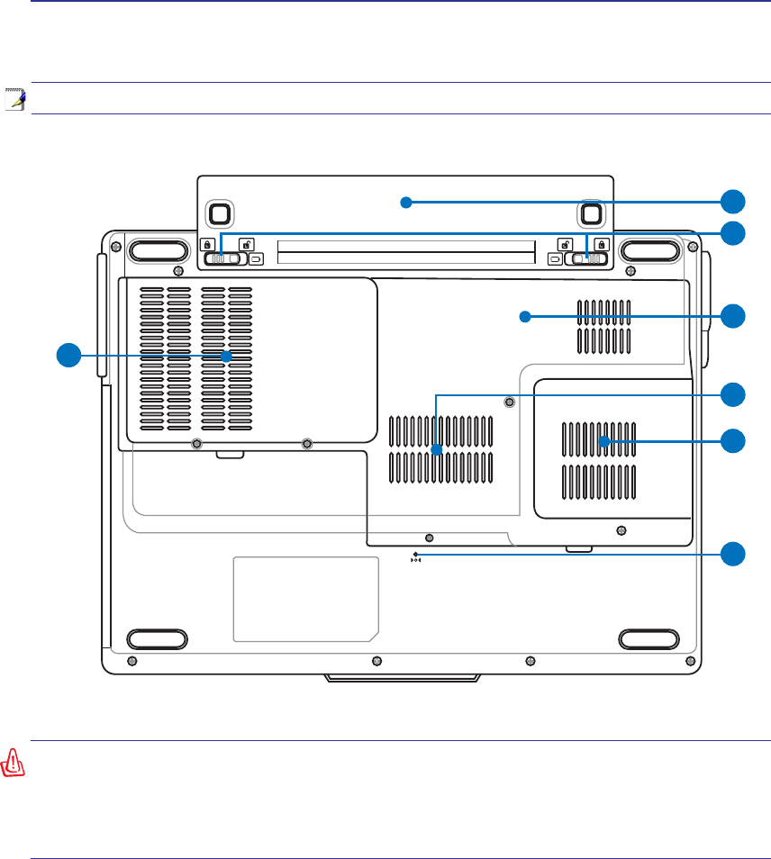
Bottom Side
Refer to the diagram below to identify the components on this side of the Notebook PC.
5
6
7
3
4
1
2
WARNING! The bottom of the Notebook PC can get very hot. Be careful when handling
the Notebook PC while it is in operation or recently been in operation. High tempera-
tures are normal during charging or operation. Do not use on soft surfaces such as
beds or sofas which may block the vents. DO NOT PUT THE NOTEBOOK PC ON YOUR
LAP OR OTHER PARTS OF THE BODY TO AVOID INJURY FROM THE HEAT.
NOTE: The bottom side may vary in appearance depending on model.
15
Knowing the Parts 2
2
3
4
1
6
7
5
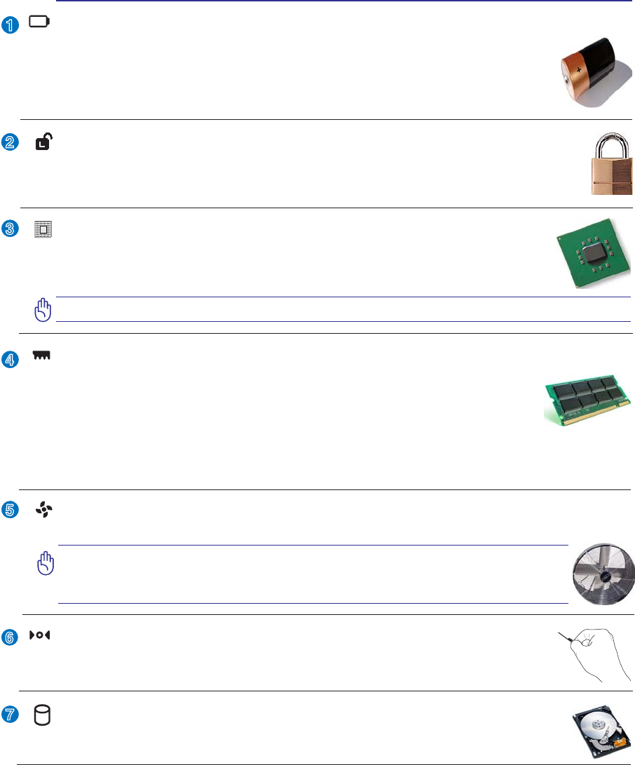
Shutdown Button (Emergency)
In case your operating system cannot properly turn OFF or restart, the shutdown button
can be pressed with a straightened paper clip to shutdown the Notebook PC.
Battery Lock - Spring
The spring battery lock is used to keep the battery pack secured. When the battery pack is in-
serted, it will automatically lock. To remove the battery pack, this spring lock must be held in
the unlocked position.
Memory (RAM) Compartment
The memory compartment provides expansion capabilities for additional memory. Addi-
tional memory will increase application performance by decreasing hard disk access. The
%,26DXWRPDWLFDOO\GHWHFWVWKHDPRXQWRIPHPRU\LQWKHV\VWHPDQGFRQÀJXUHV&026
accordingly during the POST (Power-On-Self-Test) process. There is no hardware or
software (including BIOS) setup required after the memory is installed. Visit an authorized service center
or retailer for information on memory upgrades for your Notebook PC. Only purchase expansion modules
from authorized retailers of this Notebook PC to ensure maximum compatibility and reliability.
Central Processor Unit (CPU) Compartment
Some Notebook PC models feature a socketed-processor design to allow upgrading to faster
processors in the future. Some models feature a ULV design for compactness and may not
be upgraded. Visit an authorized service center or retailer for information on upgrades.
WARNING! End-user removal of the CPU or hard disk drive will void the warranty.
Hard Disk Drive Compartment
The hard disk drive is secured in a compartment. Hard disk drive upgrades are to be done
by authorized service centers or dealers only.
Battery Pack
The battery pack is automatically charged when the Notebook PC is connected to an AC
power source and maintains power to the Notebook PC when AC power is not connected.
This allows use when moving temporarily between locations. Battery time varies by usage
DQGE\WKHVSHFLÀFDWLRQVIRUWKLV1RWHERRN3&7KHEDWWHU\SDFNFDQQRWEHGLVDVVHPEOHG
and must be purchased as a single unit.
Cooling Fan
The cooling fan is activated to remove excess heat depending on temperature threshold settings.
IMPORTANT! Make sure that paper, books, clothing, cables, or other objects
do not block any of the air vents or else overheating of the Notebook PC
may occur.
16
2 Knowing the Parts
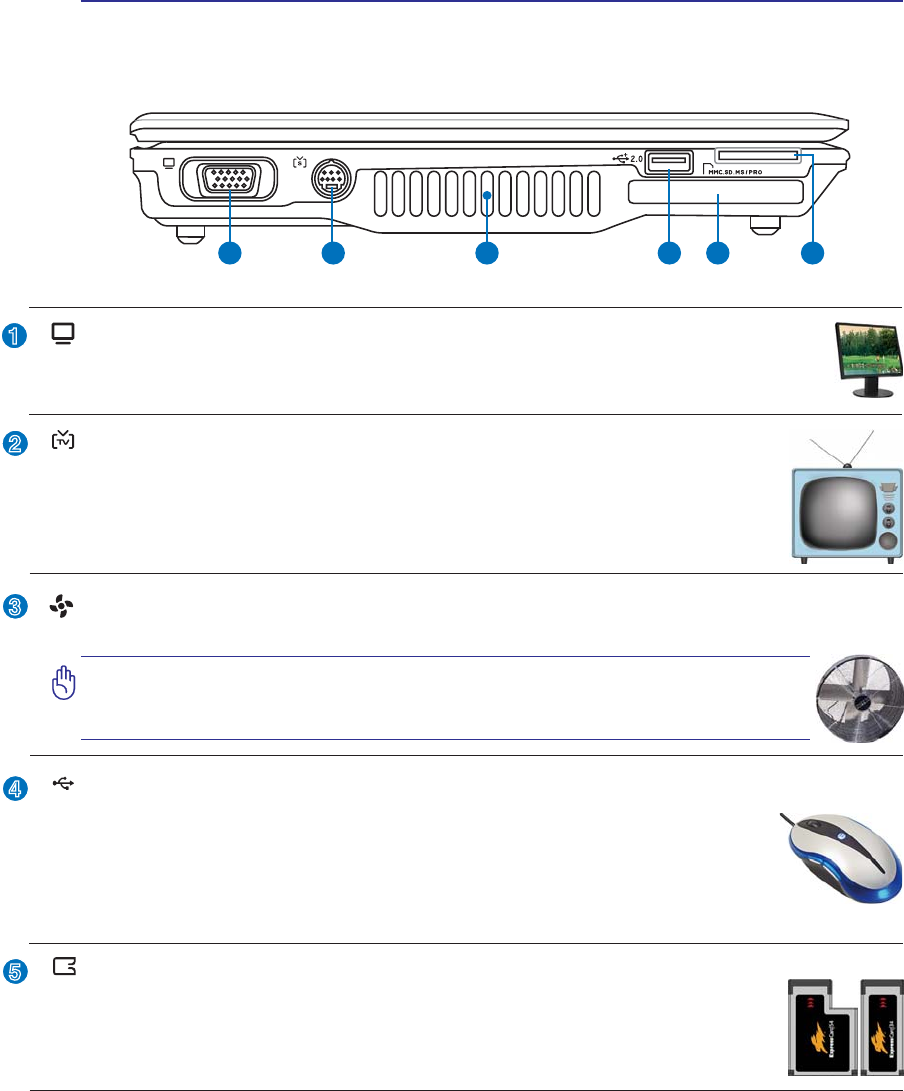
Left Side
Refer to the diagram below to identify the components on this side of the Notebook PC.
2
3
4
1
5
1 2 3 4 5 6
ExpressCard Slot
One 26pin Express card slot is available to support one ExpressCard/34mm or one
ExpressCard/54mm expansion card. This new interface is faster by using a serial bus
supporting USB 2.0 and PCI Express instead of the slower parallel bus used in the PC
card slot. (Not compatible with previous PCMCIA cards.)
(continued on next page)
Air Vents
The air vents allow cool air to enter and warm air to exit the Notebook PC.
IMPORTANT! Make sure that paper, books, clothing, cables, or other objects
do not block any of the air vents or else overheating of the Notebook PC
may occur.
Display (Monitor) Output
7KHSLQ'VXEPRQLWRUSRUWVXSSRUWVDVWDQGDUG9*$FRPSDWLEOHGHYLFHVXFKDVDPRQLWRU
or projector to allow viewing on a larger external display.
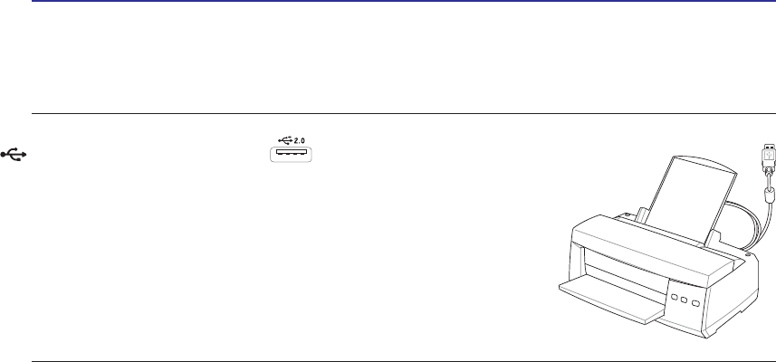
2.0
USB Port (2.0/1.1)
The USB (Universal Serial Bus) port is compatible with USB 2.0 or USB 1.1 devices
such as keyboards, pointing devices, cameras, hard disk drives, printers, and scanners
connected in a series up to 12Mbits/sec (USB 1.1) and 480Mbits/sec (USB 2.0). USB
allows many devices to run simultaneously on a single computer, with some peripherals
acting as additional plug-in sites or hubs. USB supports hot-swapping of devices so that most
peripherals can be connected or disconnected without restarting the computer.
TV-Out Port
The TV-Out port is an S-Video connector that allows routing the Notebook PC’s display
to a television or video projection device. You can choose between simultaneously or
single display. Use an S-Video cable (not provided) for high quality displays or use the
provided RCA to S-Video adapter for standard video devices. This port supports both
NTSC and PAL formats.
17
Knowing the Parts 2
6
Flash Memory Slot
Normally a PCMCIA or USB memory card reader must be purchased separately in
order to use memory cards from devices such as digital cameras, MP3 players, mobile
SKRQHVDQG3'$V7KLV1RWHERRN3&KDVDEXLOWLQPHPRU\FDUGUHDGHUWKDWFDQUHDG
PDQ\ÁDVKPHPRU\FDUGVDVVSHFLÀHGODWHULQWKLVPDQXDO7KHEXLOWLQPHPRU\FDUGUHDGHULV
not only convenient, but also faster than most other forms of memory card readers because it
utilizes the high-bandwidth PCI bus.
18
2 Knowing the Parts
Right Side
Refer to the diagram below to identify the components on this side of the Notebook PC.
2
3
1
4
2 3 41 5 6 7 8
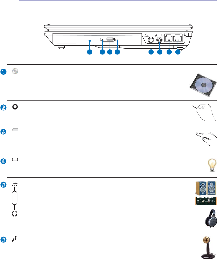
Optical Drive Electronic Eject
The optical drive eject has an electronic eject button for opening the tray. You can also eject
the optical drive tray through any software player or by right clicking the optical drive in
Windows™ “My Computer.”
Optical Drive Emergency Eject (location varies by model)
The emergency eject is used to eject the optical drive tray in case the electronic eject does
QRWZRUN'RQRWXVHWKHHPHUJHQF\HMHFWLQSODFHRIWKHHOHFWURQLFHMHFW
5
6
Optical Drive Activity Indicator (location varies by model)
The optical drive activity indicator shows when data is being transferred by the optical disk drive.
This indicator will light in proportion to the data size transferred.
Optical Drive
The Notebook PC comes in various models with different optical drives. The Notebook
3&·VRSWLFDOGULYHPD\VXSSRUWFRPSDFWGLVFV&'DQGRUGLJLWDOYLGHRGLVFV'9'DQG
PD\KDYHUHFRUGDEOH5RUUHZULWDEOH5:FDSDELOLWLHV6HHWKHPDUNHWLQJVSHFLÀFD-
tions for details on each model.
SPDIF Output Jack
7KLVMDFNSURYLGHVFRQQHFWLRQWR63',)6RQ\3KLOLSV'LJLWDO,QWHUIDFHFRPSOLDQWGH-
YLFHVIRUGLJLWDODXGLRRXWSXW8VHWKLVIHDWXUHWRWXUQWKH1RWHERRN3&LQWRDKLÀKRPH
entertainment system.
Headphone Output Jack
The stereo headphone jack (1/8 inch) is used to connect the Notebook PC’s audio out signal to
DPSOLÀHGVSHDNHUVRUKHDGSKRQHV8VLQJWKLVMDFNDXWRPDWLFDOO\GLVDEOHVWKHEXLOWLQVSHDNHUV
Combo
Microphone Input Jack
The mono microphone jack (1/8 inch) can be used to connect an external microphone or output
signals from audio devices. Using this jack automatically disables the built-in microphone. Use
this feature for video conferencing, voice narrations, or simple audio recordings.
19
Knowing the Parts 2
7
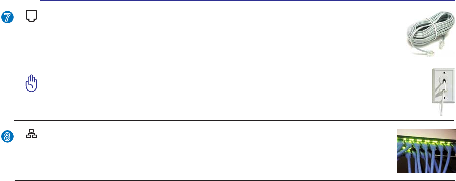
Modem Port
The RJ-11 modem port with two pins is smaller than the RJ-45 LAN port and supports
a standard telephone cable. The internal modem supports up to 56K V.90 transfers. The
built-in connector allows convenient use without additional adapters.
IMPORTANT! The built-in modem does not support the voltage used in digital
phone systems. Do not connect the modem port to a digital phone system or
else damage will occur to the Notebook PC.
LAN Port
The RJ-45 LAN port with eight pins is larger than the RJ-11 modem port and supports a
standard Ethernet cable for connection to a local network. The built-in connector allows
convenient use without additional adapters.
8
20
2 Knowing the Parts
Rear Side
Refer to the diagram below to identify the components on this side of the Notebook PC.
1 2 3 4
1
2
3
4
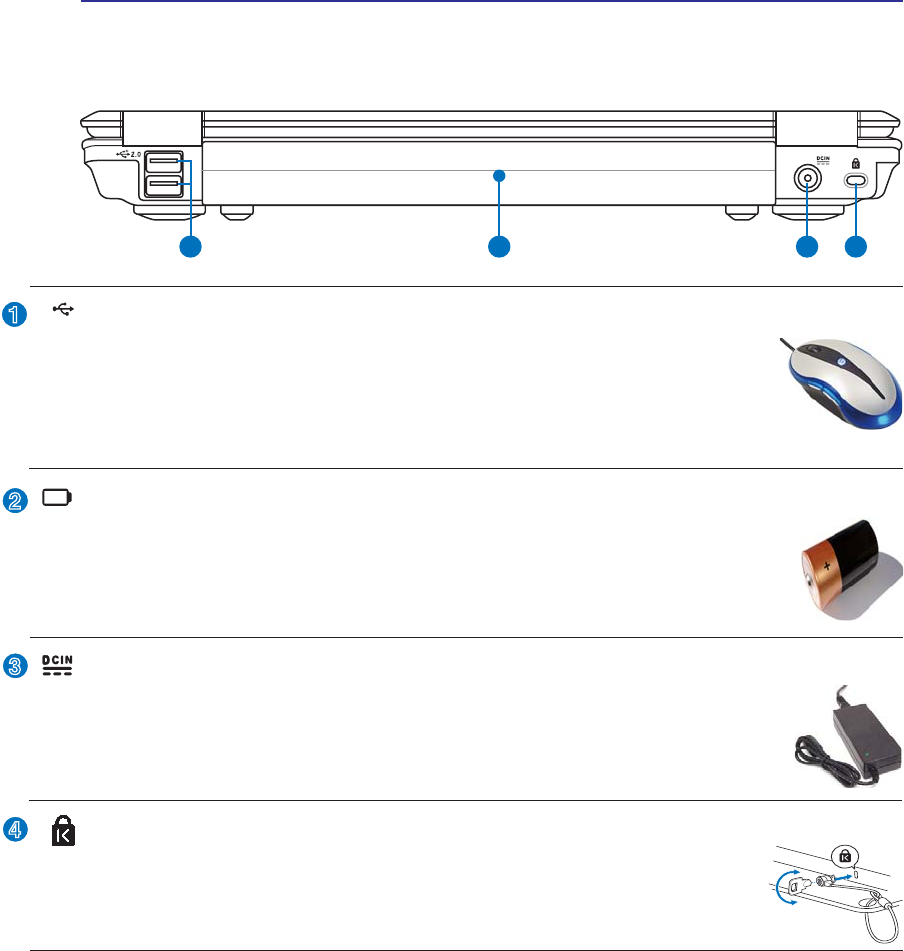
Kensington® Lock Port
The Kensington® lock port allows the Notebook PC to be secured using Kensington®
compatible Notebook PC security products. These security products usually include a
PHWDOFDEOHDQGORFNWKDWSUHYHQWWKH1RWHERRN3&WREHUHPRYHGIURPDÀ[HGREMHFW
Some security products may also include a motion detector to sound an alarm when moved.
Battery Pack
The battery pack is automatically charged when the Notebook PC is connected to an AC
power source and maintains power to the Notebook PC when AC power is not connected.
This allows use when moving temporarily between locations. Battery time varies by usage
DQGE\WKHVSHFLÀFDWLRQVIRUWKLV1RWHERRN3&7KHEDWWHU\SDFNFDQQRWEHGLVDVVHPEOHG
and must be purchased as a single unit.
2.0
USB Port (2.0/1.1)
The USB (Universal Serial Bus) port is compatible with USB 2.0 or USB 1.1 devices
such as keyboards, pointing devices, cameras, hard disk drives, printers, and scanners
connected in a series up to 12Mbits/sec (USB 1.1) and 480Mbits/sec (USB 2.0). USB
allows many devices to run simultaneously on a single computer, with some peripherals
acting as additional plug-in sites or hubs. USB supports hot-swapping of devices so that most
peripherals can be connected or disconnected without restarting the computer.
Power (DC) Input
7KHVXSSOLHGSRZHUDGDSWHUFRQYHUWV$&SRZHUWR'&SRZHUIRUXVHZLWKWKLVMDFN3RZHUVXS-
plied through this jack supplies power to the Notebook PC and charges the internal battery pack.
To prevent damage to the Notebook PC and battery pack, always use the supplied power
adapter. CAUTION: MAY BECOME WARM TO HOT WHEN IN USE. BE SURE
NOT TO COVER THE ADAPTER AND KEEP IT AWAY FROM YOUR BODY.
21
Knowing the Parts 2
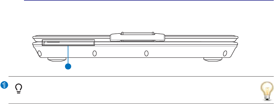
Front Side
Refer to the diagram below to identify the components on this side of the Notebook PC.
1
1
Status Indicators (front)
Status indicators represent various hardware/software conditions. See indicator details in section 3.

22
3 Getting Started

23
3. Getting Started
Using AC Power
Using Battery Power
Powering ON the Notebook PC
Checking Battery Power
Restarting or Rebooting
Powering OFF the Notebook PC
Special Keyboard Functions
Switches and Status Indicators
24
3 Getting Started
IMPORTANT! Damage may occur if you use a different adapter to power the Notebook
PC or use the Notebook PC’s adapter to power other electrical devices. If there is
smoke, burning scent, or extreme heat coming from the AC-DC adapter, seek servic-
ing. Seek servicing if you suspect a faulty AC-DC adapter. You may damage both your
battery pack(s) and the Notebook PC with a faulty AC-DC adapter.
NOTE: This Notebook PC may come with either a two or three-prong plug depending
on territory. If a three-prong plug is provided, you must use a grounded AC outlet or
use a properly grounded adapter to ensure safe operation of the Notebook PC.
WARNING! THE POWER ADAPTER MAY BECOME WARM TO HOT WHEN IN USE. BE
SURE NOT TO COVER THE ADAPTER AND KEEP IT AWAY FROM YOUR BODY.
Power System
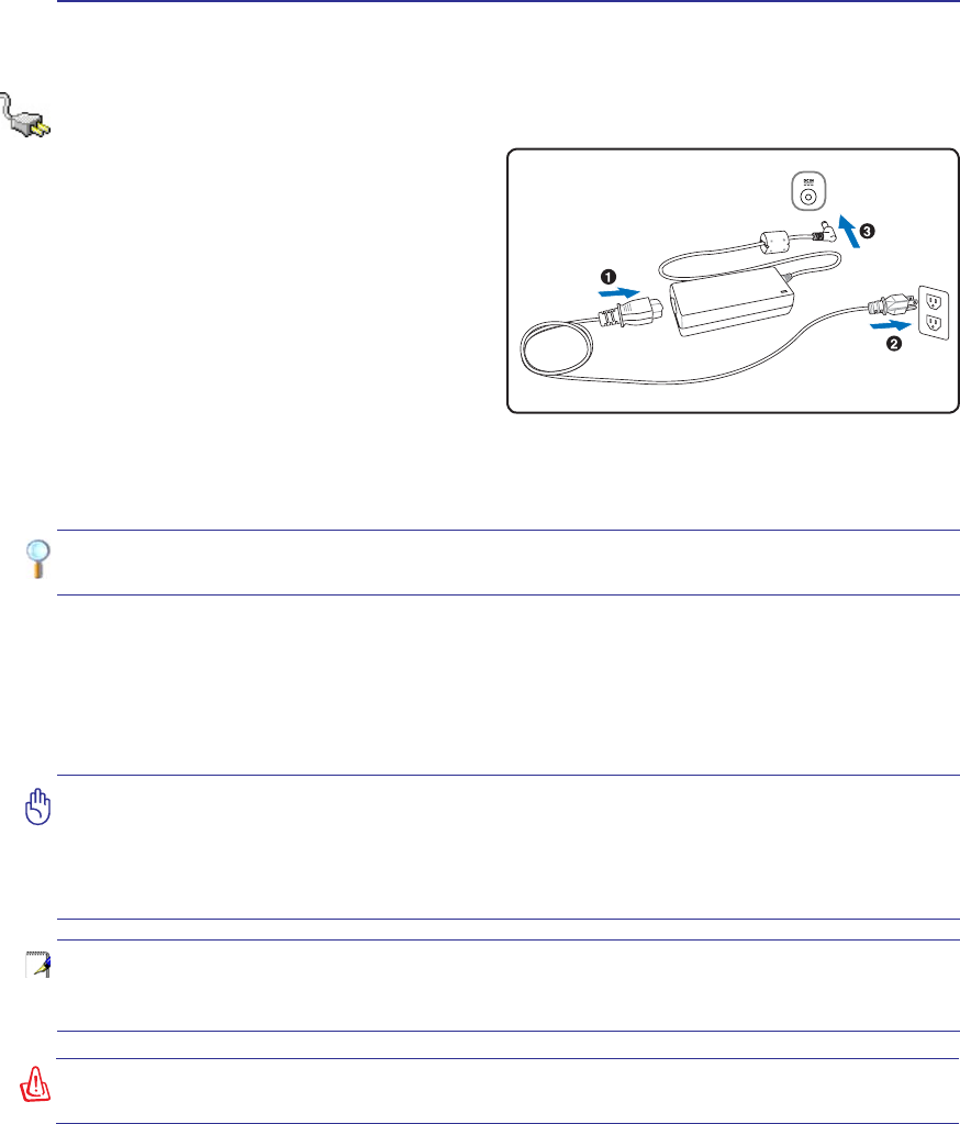
Using AC Power
The Notebook PC power is comprised of two parts,
the power adapter and the battery power system.
The power adapter converts AC power from a wall
RXWOHWWRWKH'&SRZHUUHTXLUHGE\WKH1RWHERRN
PC. Your Notebook PC comes with a universal
$&'&DGDSWHU7KDWPHDQVWKDW\RXPD\FRQQHFW
the power cord to any 100V-120V as well as 220V-
240V outlets without setting switches or using
SRZHUFRQYHUWHUV'LIIHUHQWFRXQWULHVPD\UHTXLUH
that an adapter be used to connect the provided
US-standard AC power cord to a different standard.
Most hotels will provide universal outlets to sup-
port different power cords as well as voltages. It is always best to ask an experienced traveler about AC
outlet voltages when bringing power adapters to another country.
TIP: You can buy travel kits for the Notebook PC that includes power and modem
adapters for almost every country.
:LWKWKH$&SRZHUFRUGFRQQHFWHGWRWKH$&'&FRQYHUWHUFRQQHFWWKH$&SRZHUFRUGWRDQ$&RXWOHW
SUHIHUDEO\ZLWKVXUJHSURWHFWLRQDQGWKHQFRQQHFWWKH'&SOXJWRWKH1RWHERRN3&&RQQHFWLQJWKH
$&'&DGDSWHUWRWKH$&RXWOHWÀUVWDOORZV\RXWRWHVWWKH$&RXWOHW·VSRZHUDQGWKH$&'&FRQYHUWHU
LWVHOIIRUFRPSDWLELOLW\SUREOHPVEHIRUHFRQQHFWLQJWKH'&SRZHUWRWKH1RWHERRN3&7KHSRZHULQGL-
cator on the adapter (if available) will light if the power is within accepted ranges.
25
Getting Started 3
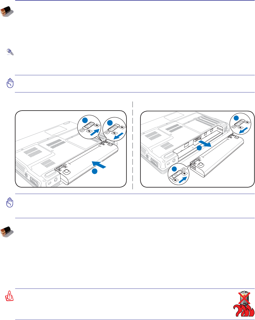
IMPORTANT! Never attempt to remove the battery pack while the Notebook PC is
turned ON, as this may result in the loss of working data.
IMPORTANT! Only use battery packs and power adapters supplied with this Notebook
3&RUVSHFLÀFDOO\DSSURYHGE\WKHPDQXIDFWXUHURUUHWDLOHUIRUXVHZLWKWKLVPRGHORU
else damage may occur to the Notebook PC.
2
31
3
1
2
To install the battery pack: To remove the battery pack:
:$51,1*)RUVDIHW\UHDVRQV'2127WKURZWKHEDWWHU\LQÀUH'2127
short circuit the contacts, and DO NOT disassemble the battery. If there is
any abnormal operation or damage to the battery pack caused by impact,
turn OFF the Notebook PC and contact an authorized service center.
Battery Care
The Notebook PC’s battery pack, like all rechargeable batteries, has a limit on the number times it can
be recharged. The battery pack’s useful life will depend on your environment temperature, humidity, and
KRZ\RXU1RWHERRN3&LVXVHG,WLVLGHDOWKDWWKHEDWWHU\EHXVHGLQDWHPSHUDWXUHUDQJHEHWZHHQÝ&
DQGÝ&Ý)DQGÝ)<RXPXVWDOVRWDNHLQWRDFFRXQWWKDWWKH1RWHERRN3&·VLQWHUQDOWHPSHUDWXUH
is higher than the outside temperature. Any temperatures above or below this range will shorten the life
of the battery. But in any case, the battery pack’s usage time will eventually decrease and a new battery
pack must be purchased from an authorized dealer for this Notebook PC. Because batteries also have a
shelf life, it is not recommended to buy extras for storing.
Using Battery Power
The Notebook PC is designed to work with a removable battery pack. The battery pack consists of a set
of battery cells housed together. A fully charged pack will provide several hours of battery life, which
can be further extended by using power management features through the BIOS setup. Additional battery
packs are optional and can be purchased separately through a Notebook PC retailer.
Installing and Removing the Battery Pack
Your Notebook PC may or may not have its battery pack installed. If your Notebook PC does not have
its battery pack installed, use the following procedures to install the battery pack.

26
3 Getting Started
IMPORTANT! If warnings are still given during bootup after running a software disk
checking utility, you should take your Notebook PC in for servicing. Continued use
may result in data loss.
IMPORTANT! To protect the hard disk drive, always wait at least 5 seconds after turn-
ing OFF your Notebook PC before turning it back ON.
127(%HIRUHERRWXSWKHGLVSOD\SDQHOÁDVKHVZKHQWKHSRZHULVWXUQHG217KLVLV
part of the Notebook PC’s test routine and is not a problem with the display.
WARNING! DO NOT carry or cover a Notebook PC that is powered ON with any materi-
als that will reduce air circulation such as a carrying bag.
Powering ON the Notebook PC
The Notebook PC’s power-ON message appears on the screen when you turn it ON. If necessary, you
may adjust the brightness by using the hot keys. If you need to run the BIOS Setup to set or modify the
V\VWHPFRQÀJXUDWLRQSUHVV>)@XSRQERRWXSWRHQWHUWKH%,266HWXS,I\RXSUHVV>7DE@GXULQJWKH
VSODVKVFUHHQVWDQGDUGERRWLQIRUPDWLRQVXFKDVWKH%,26YHUVLRQFDQEHVHHQ3UHVV>(6&@DQG\RXZLOO
be presented with a boot menu with selections to boot from your available drives.
The Power-On Self Test (POST)
:KHQ\RXWXUQ21WKH1RWHERRN3&LWZLOOÀUVWUXQWKURXJKDVHULHVRIVRIWZDUHFRQWUROOHGGLDJQRV-
tic tests called the Power-On Self Test (POST). The software that controls the POST is installed as a
permanent part of the Notebook PC’s architecture. The POST includes a record of the Notebook PC’s
KDUGZDUHFRQÀJXUDWLRQZKLFKLVXVHGWRPDNHDGLDJQRVWLFFKHFNRIWKHV\VWHP7KLVUHFRUGLVFUHDWHG
by using the BIOS Setup program. If the POST discovers a difference between the record and the exist-
LQJKDUGZDUHLWZLOOGLVSOD\DPHVVDJHRQWKHVFUHHQSURPSWLQJ\RXWRFRUUHFWWKHFRQÁLFWE\UXQQLQJ
BIOS Setup. In most cases the record should be correct when you receive the Notebook PC. When the
WHVWLVÀQLVKHG\RXPD\JHWDPHVVDJHUHSRUWLQJ´1RRSHUDWLQJV\VWHPIRXQGµLIWKHKDUGGLVNZDVQRW
preloaded with an operating system. This indicates that the hard disk is correctly detected and ready for
the installation of a new operating system.
Self Monitoring and Reporting Technology
The S.M.A.R.T. (Self Monitoring and Reporting Technology) checks the hard disk drive during POST and
gives a warning message if the hard disk drive requires servicing. If any critical hard disk drive warning
is given during bootup, backup your data immediately and run Windows disk checking program. To run
Window’s disk checking program: (1) right-click any hard disk drive icon in “My Computer”, (2) choose
Properties, (3) click the Tools tab, (4) click Check Now, (5) select a hard disk drive, (6) select Thorough to
also check for physical damages, and (7) click Start. Third party disk utilities such as Symantec’s Norton
'LVN'RFWRUFDQDOVRSHUIRUPWKHVDPHIXQFWLRQVEXWZLWKJUHDWHUHDVHDQGPRUHIHDWXUHV
27
Getting Started 3
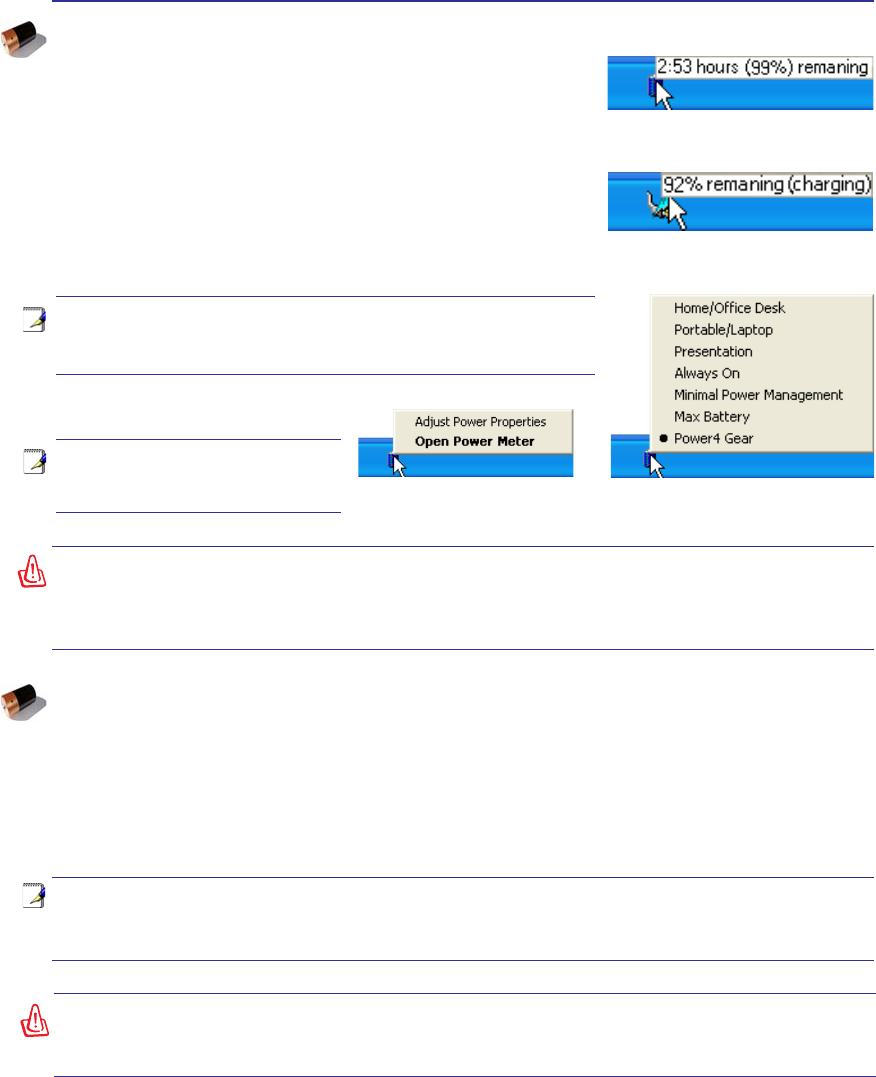
NOTE: You will be warned when battery power is low. If you
continue to ignore the low battery warnings, the Notebook PC
eventually enters suspend mode (Windows default uses STR).
WARNING! Suspend-to-RAM (STR) does not last long when the battery power is depleted.
Suspend-to-Disk (STD) is not the same as power OFF. STD requires a small amount of
power and will fail if no power is available due to complete battery depletion or no power
supply (e.g. removing both the power adapter and battery pack).
Right-click the battery icon for
sub-menus. Left-click the battery icon for power
management settings.
Note: Screen captures shown here
are examples only and may not re-
ÁHFWZKDW\RXVHHLQ\RXUV\VWHP
Move your mouse over the battery icon
for remaining power information.
When the AC power is connected,
charging status will be shown.
WARNING! Do not leave the battery pack discharged. The battery pack will discharge
over time. If not using a battery pack, it must continued to be charged every three
months to extend recovery capacity or else it may fail to charge in the future.
NOTE: The battery stops charging if the temperature is too high or the battery voltage
is too high. BIOS provides a smart battery refreshing function. If the battery calibration
process fails, stop charging and contact an authorized service center.
Checking Battery Power
The battery system implements the Smart Battery standard under
the Windows environment, which allows the battery to accurately
report the amount of charge left in the battery. A fully-charged battery
pack provides the Notebook PC a few hours of working power. But
WKHDFWXDOÀJXUHYDULHVGHSHQGLQJRQKRZ\RXXVHWKHSRZHUVDYLQJ
features, your general work habits, the CPU, system memory size,
and the size of the display panel.
To check the remaining battery power, move your cursor over the
power icon. The power icon is a “battery” when not using AC power
DQGD´SOXJµZKHQXVLQJ$&SRZHU'RXEOHFOLFNRQWKHLFRQIRU
more information and settings.
Charging the Battery Pack
Before you use your Notebook PC on the road, you will have to charge the battery pack. The battery pack
begins to charge as soon as the Notebook PC is connected to external power using the power adapter.
)XOO\FKDUJHWKHEDWWHU\SDFNEHIRUHXVLQJLWIRUWKHÀUVWWLPH$QHZEDWWHU\SDFNPXVWFRPSOHWHO\FKDUJH
before the Notebook PC is disconnected from external power. It takes a few hours to fully charge the
battery when the Notebook PC is turned OFF and may take twice the time when the Notebook PC is
turned ON. The battery charge light turns OFF when the battery pack is charged.
28
3 Getting Started
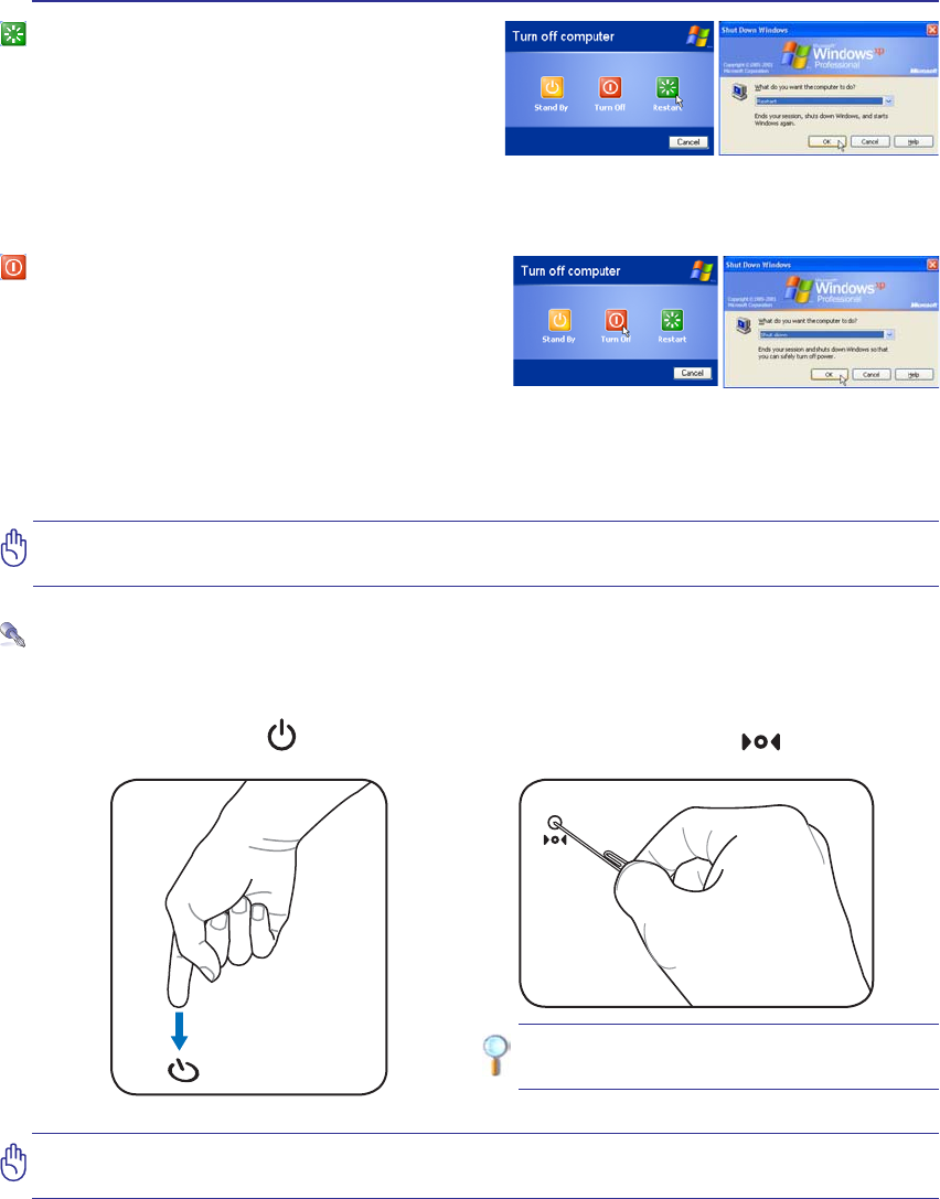
Restarting or Rebooting
After making changes to your operating system,
you may be prompted to restart the system. Some
installation processes will provide a dialog box to
allow restart. To restart the system manually, click
:LQGRZV 6WDUW EXWWRQ DQG VHOHFW 6KXW 'RZQ DQG
then choose Restart.
Powering OFF
In Windows XP, power OFF the Notebook PC by
FOLFNLQJ:LQGRZV6WDUWEXWWRQDQGVHOHFW6KXW'RZQ
and then choose Turn off (or Shut down). For oper-
ating systems without proper power management
'26:LQGRZV17\RXPXVWFORVHDOODSSOLFDWLRQV
and exit operating systems and then power OFF by holding the power switch for 2 seconds (as opposed
to 1 second to power ON). Holding the power switch for 2 seconds is necessary in order to prevent ac-
cidental power-OFFs.
IMPORTANT! To protect the hard drive, wait at least 5 seconds after turning OFF your
Notebook PC before turning it back ON.
(Screens are different depending on security settings.)
IMPORTANT! Do not use emergency shutdown while data is being written; doing so
can result in loss or destruction of your data.
TIP: Use a straightened paper clip to
press the shutdown button.
Emergency Shutdown
In case your operating system cannot properly turn OFF or restart, there are two additional ways to
shutdown your Notebook PC:
(1) Hold the power button over 4 seconds, or (2) Press the shutdown button .
29
Getting Started 3
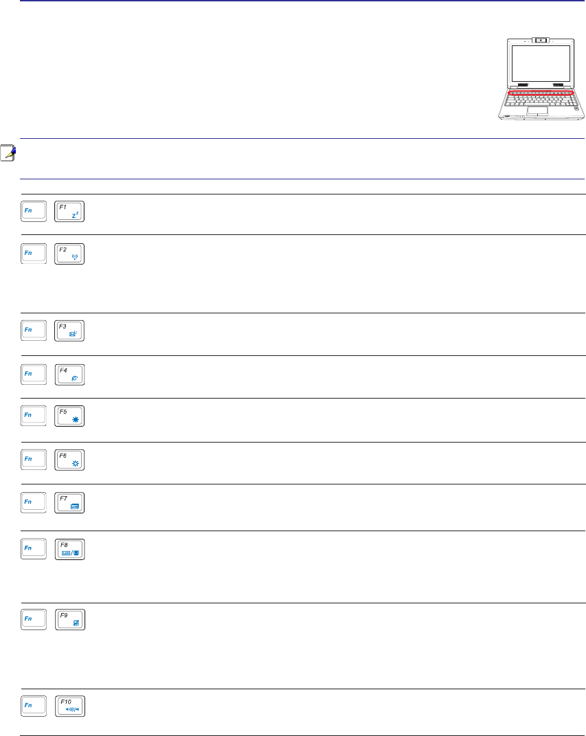
Special Keyboard Functions
Colored Hot Keys
7KH IROORZLQJ GHÀQHV WKH FRORUHG KRW NH\V RQ WKH 1RWHERRN 3&·V NH\ERDUG 7KH
FRORUHGFRPPDQGVFDQRQO\EHDFFHVVHGE\ÀUVWSUHVVLQJDQGKROGLQJWKHIXQFWLRQ
key while pressing a key with a colored command.
1.3
MEGA
PIXELS
OFF ON
ASUS WIDE SCREEN NOTEBOOK
NOTE: The Hot Key locations on the function keys may vary depending on model but the
functions should remain the same. Follow the icons instead of the function keys.
(continued on next page)
Radio Tower (F2): Wireless Models Only: Toggles the internal wireless LAN or Blue-
tooth (on selected models) ON or OFF with an on-screen-display. When enabled, the cor-
responding wireless indicator will light. Windows software settings are necessary to use
the wireless LAN or Bluetooth.
Envelope Icon (F3): Pressing this button will launch your Email application while Win-
dows is running.
“e” Icon (F4): Pressing this button will launch your Internet browser application while
Windows is running.
Filled Sun Icon (F5):
'HFUHDVHVWKHGLVSOD\EULJKWQHVV
“Zz” Icon (F1): Places the Notebook PC in suspend mode (either Save-to-RAM or Save-
WR'LVNGHSHQGLQJRQVOHHSEXWWRQVHWWLQJLQSRZHUPDQDJHPHQWVHWXS
LCD Icon (F7): Toggles the display panel ON and OFF. This also stretches your screen
DUHDRQFHUWDLQPRGHOVWRÀOOWKHHQWLUHGLVSOD\ZKHQXVLQJORZUHVROXWLRQPRGHV
Open Sun Icon (F6):
Increases the display brightness
Speaker Icons (F10):
Toggles the speakers ON and OFF (only in Windows OS)
LCD/Monitor Icons (F8):7RJJOHVEHWZHHQWKH1RWHERRN3&·V/&'GLVSOD\DQGDQH[WHUQDO
PRQLWRULQWKLVVHULHV1RWHERRN3&/&'!([WHUQDO0RQLWRU!%RWK7KLVIXQFWLRQGRHV
QRWZRUNLQ&RORUVVHOHFW+LJK&RORULQ'LVSOD\3URSHUW\6HWWLQJVIMPORTANT:
Connect an external monitor before booting up the Notebook PC.
Crossed-out Touchpad (F9)7RJJOHVWKHEXLOWLQWRXFKSDG/2&.('GLVDEOHGDQG81-
/2&.('HQDEOHG/RFNLQJWKHWRXFKSDGZLOOSUHYHQW\RXIURPDFFLGHQWDOO\PRYLQJWKH
cursor while typing and is best used with an external pointing device such as a mouse. Note:
$QLQGLFDWRUEHWZHHQWKHWRXFKSDGEXWWRQVZLOOOLJKWZKHQWKHWRXFKSDGLV81/2&.('
HQDEOHGDQGQRWOLJKWZKHQWKHWRXFKSDGLV/2&.('GLVDEOHG
30
3 Getting Started
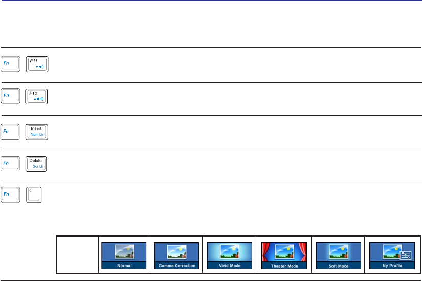
Colored Hot Keys (Cont.)
Fn+C: Toggles “Splendid Video Intelligent Technology” function ON and OFF. This al-
lows switching between different display color enhancement modes in order to improve
contrast, brightness, skin tone, and color saturation for red, green, and blue independently.
<RXFDQVHHWKHFXUUHQWPRGHWKURXJKWKHRQVFUHHQGLVSOD\26'
OSD
Icons
Speaker Down Icon (F11):
'HFUHDVHVWKHVSHDNHUYROXPHRQO\LQ:LQGRZV26
Speaker Up Icon (F12):
Increases the speaker volume (only in Windows OS)
Num Lk (Ins): Toggles the numeric keypad (number lock) ON and OFF. Allows you to
use a larger portion of the keyboard for number entering.
Scr Lk (Del): Toggles the “Scroll Lock” ON and OFF. Allows you to use a larger portion
of the keyboard for cell navigation.
31
Getting Started 3
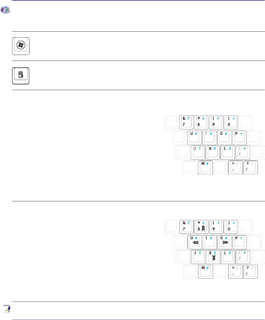
NOTE: The arrow symbols are illustrated here for your reference. They are not labeled
on the keyboard as shown here.
Microsoft Windows Keys
There are two special Windows keys on the keyboard as described below.
The key with the Windows Logo activates the Start menu located at the bottom left of the Win-
dows desktop.
The other key, that looks like a Windows menu with a small cursor, activates the properties menu
and is equivalent to pressing the right mouse button on a Windows object.
Keyboard as a Numeric Keypad
The numeric keypad is embedded in the keyboard and
consists of 15 keys that make number intensive input more
convenient. These dual-purpose keys are labeled in orange on
the key caps. Numeric assignments are located at the upper
ULJKWKDQGFRUQHURIHDFKNH\DVVKRZQLQWKHÀJXUH:KHQ
WKHQXPHULFNH\SDGLVHQJDJHGE\SUHVVLQJ>Fn@>Ins/Num
LK@WKHQXPEHUORFN/('OLJKWVXS,IDQH[WHUQDONH\ERDUG
LV FRQQHFWHG SUHVVLQJ WKH >Ins/Num LK@ RQ WKH H[WHUQDO
keyboard enables/disables the NumLock on both keyboards
simultaneously. To disable the numeric keypad while keeping
WKHNH\SDGRQDQH[WHUQDONH\ERDUGDFWLYDWHGSUHVVWKH>Fn@>Ins/Num LK@NH\VRQWKH1RWHERRN3&
Keyboard as Cursors
The keyboard can be used as cursors while Number Lock is
ON or OFF in order to increase navigation ease while entering
numeric data in spreadsheets or similar applications.
With Number Lock OFFSUHVV>Fn@DQGRQHRIWKHFXUVRU
NH\VVKRZQEHORZ)RUH[DPSOH>Fn@>8@IRUXS>Fn@>.@IRU
GRZQ>Fn@>U@IRUOHIWDQG>Fn@>O@IRUULJKW
With Number Lock ONXVH>Shift@DQGRQHRIWKHFXUVRU
NH\VVKRZQEHORZ)RUH[DPSOH>Shift@>8@IRUXS>Shift@>K@
IRUGRZQ>Shift@>U@IRUOHIWDQG>Shift@>O@IRUULJKW
32
3 Getting Started
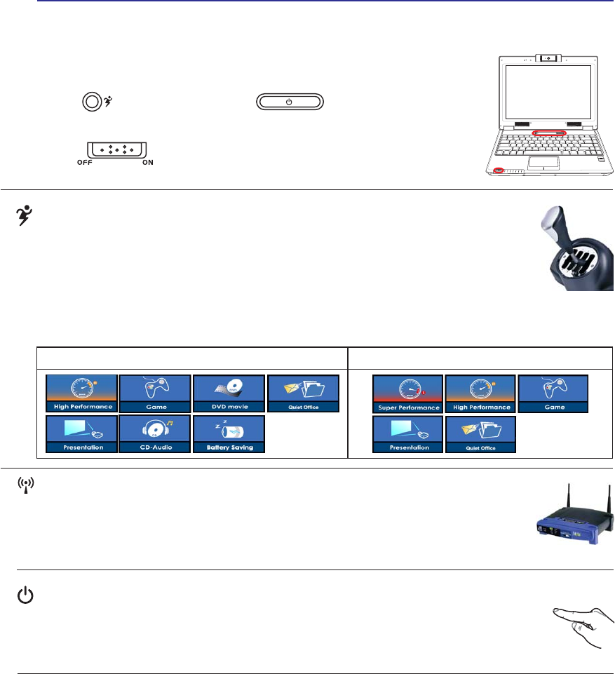
Power Switch
The power switch allows powering ON and OFF the Notebook PC and recovering from
67'8VHWKHVZLWFKRQFHWRWXUQ21DQGRQFHWRWXUQ2))WKH1RWHERRN3&,Q:LQGRZV
XP, this button can also be used to safely turn OFF the Notebook PC. The power switch only
works when the display panel is opened.
Switches
Switches and Status Indicators
1.3
MEGA
PIXELS
OFF ON
ASUS WIDE SCREEN NOTEBOOK
Battery Mode AC Mode
Power4 Gear+ Key
The Power4 Gear+ button toggles power savings between various power saving modes. The
power saving modes control many aspects of the Notebook PC to maximize performance
versus battery time.
When you are using an AC power adapter, Power4 Gear+ will switch between modes in the
AC power mode segment. When you remove the AC adapter, Power4 Gear+ will switch between modes
LQWKHEDWWHU\'&PRGHVHJPHQW:KHQ\RXUHPRYHRUDSSO\WKH$&DGDSWHU3RZHU*HDUZLOODX-
WRPDWLFDOO\VKLIW\RXXSRUGRZQLQWRWKHSURSHUPRGHVHJPHQW$&RU'&
Wireless Switch
Wireless Models Only: Toggles the internal wireless LAN or Bluetooth (on selected
models) ON or OFF with an on-screen-display. When enabled, the corresponding wireless
indicator will light. Windows software settings are necessary to use the wireless LAN or
Bluetooth.
33
Getting Started 3
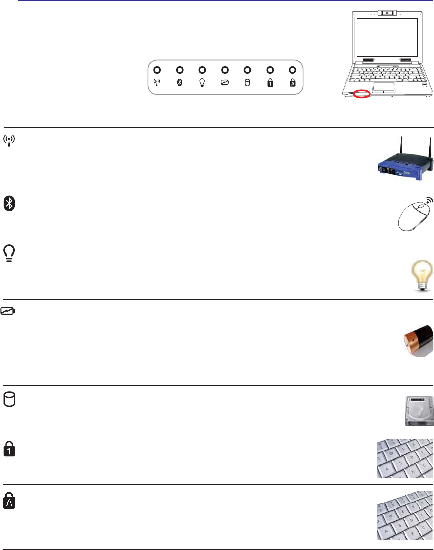
Status Indicators
Front
Battery Charge Indicator
7KHEDWWHU\FKDUJHLQGLFDWRULVDQ/('WKDWVKRZVWKHVWDWXVRIWKHEDWWHU\·VSRZHUDVIROORZV
ON: The Notebook PC’s battery is charging when AC power is connected.
OFF: The Notebook PC’s battery is charged or completely drained.
Blinking: Battery power is less than 10% and the AC power is not connected.
1.3
MEGA
PIXELS
OFF ON
ASUS WIDE SCREEN NOTEBOOK
Wireless Indicator
This is only applicable on models with built-in wireless LAN and/or built-in Bluetooth.
When the built-in wireless LAN and/or built-in Bluetooth is enabled, this indicator will
light. (Windows software settings are necessary.)
Power Indicator
The power indicator lights when the Notebook PC is turned ON and blinks slowly when the Note-
book PC is in the Suspend-to-RAM (Standby) mode. This indicator is OFF when the Notebook
3&LVWXUQHG2))RULQWKH6XVSHQGWR'LVN+LEHUQDWLRQPRGH
Drive Activity Indicator
Indicates that the Notebook PC is accessing one or more storage device(s) such as the hard
GLVN7KHOLJKWÁDVKHVSURSRUWLRQDOWRWKHDFFHVVWLPH
Bluetooth Indicator
This is only applicable on models with internal Bluetooth (BT). This indicator will light to
show that the Notebook PC’s built-in Bluetooth (BT) function is activated.
Capital Lock Indicator
,QGLFDWHVWKDWFDSLWDOORFN>&DSV/RFN@LVDFWLYDWHGZKHQOLJKWHG&DSLWDOORFNDOORZVVRPH
of the keyboard letters to type using capitalized letters (e.g. A, B, C). When the capital
lock light is OFF, the typed letters will be in the lower case form (e.g. a,b,c).
Number Lock Indicator
,QGLFDWHVWKDWQXPEHUORFN>1XP/N@LVDFWLYDWHGZKHQOLJKWHG1XPEHUORFNDOORZVVRPH
of the keyboard letters to act as numbers for easier numeric data input.

34
4 Using the Notebook PC

35
4. Using the Notebook PC
Operating System
Pointing Device
Storage Devices
Expansion Card
Optical drive
Flash memory reader
Hard disk drive
Connections
Modem Connection
Network Connection
Wireless LAN Connection
Bluetooth Wireless Connection
Power Management Modes
36
4 Using the Notebook PC
Operating System
This Notebook PC may offer (depending on territory) its customers the choice of a pre-installed operat-
ing system such as Microsoft Windows XP. The choices and languages will depend on the territory.
The levels of hardware and software support may vary depending on the installed operating system. The
stability and compatibility of other operating systems cannot be guaranteed.
Support Software
7KLV1RWHERRN3&FRPHVZLWKDVXSSRUW&'WKDWSURYLGHV%,26GULYHUVDQGDS-
plications to enable hardware features, extend functionality, help manage your
Notebook PC, or add functionality not provided by the native operating system. If
XSGDWHVRUUHSODFHPHQWRIWKHVXSSRUW&'LVQHFHVVDU\FRQWDFW\RXUGHDOHUIRUZHE
sites to download individual software drivers and utilities.
7KHVXSSRUW&'FRQWDLQVDOOGULYHUVXWLOLWLHVDQGVRIWZDUHIRUDOOSRSXODURSHUDWLQJ
V\VWHPVLQFOXGLQJWKRVHWKDWKDYHEHHQSUHLQVWDOOHG7KHVXSSRUW&'GRHVQRWLQFOXGHWKHRSHUDWLQJ
V\VWHPLWVHOI7KHVXSSRUW&'LVQHFHVVDU\HYHQLI\RXU1RWHERRN3&FDPHSUHFRQÀJXUHGLQRUGHUWR
provide additional software not included as part of the factory pre-install.
$UHFRYHU\&'LVRSWLRQDODQGLQFOXGHVDQLPDJHRIWKHRULJLQDORSHUDWLQJV\VWHPLQVWDOOHGRQWKHKDUG
GULYHDWWKHIDFWRU\7KHUHFRYHU\&'SURYLGHVDFRPSUHKHQVLYHUHFRYHU\VROXWLRQWKDWTXLFNO\UHVWRUHV
the Notebook PC’s operating system to its original working state provided that your hard disk drive is
in good working order. Contact your retailer if you require such a solution.
Note: Some of the Notebook PC’s components and features may not work until the
device drivers and utilities are installed.
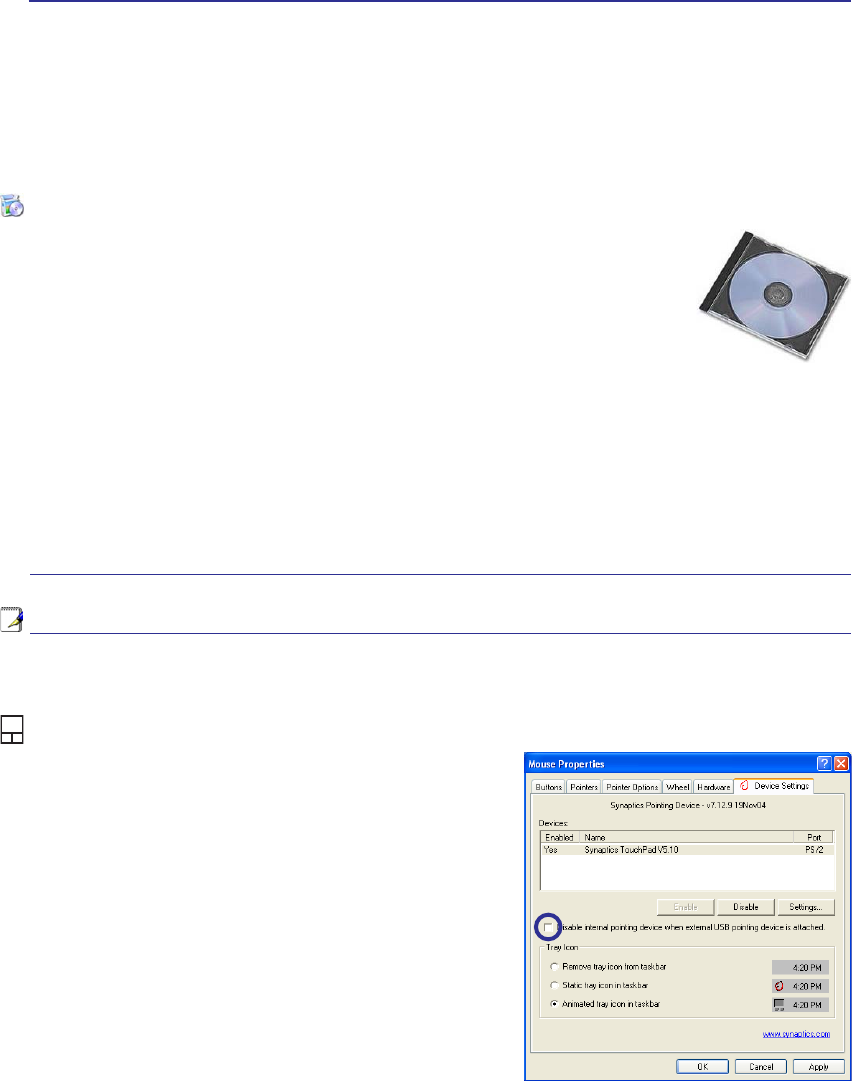
Automatic Touchpad Disabling (on selected models)
Notebook PC models with newer chipsets will automatically disable the Notebook PC’s touchpad when
an external USB mouse is attached. To turn OFF this feature,
deselect the option in Windows Control Panel - Mouse
Properties - Device Settings.
37
Using the Notebook PC 4
IMPORTANT! Do not use any objects in
SODFHRI\RXUÀQJHUWRRSHUDWHWKHWRXFK-
pad or else damage may occur to the
touchpad’s surface.
Pointing Device
The Notebook PC’s integrated touchpad pointing
device is fully compatible with all two/three-but-
ton and scrolling knob PS/2 mice. The touchpad is
pressure sensitive and contains no moving parts;
therefore, mechanical failures can be avoided. A
device driver is still required for working with some
application software.
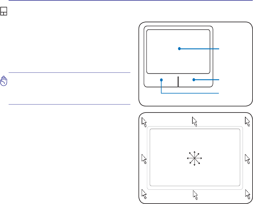
Using the Touchpad
/LJKWSUHVVXUHZLWKWKHWLSRI\RXUÀQJHULVDOOWKDWLV
required to operate the touchpad. Because the touch-
pad is electrostatic sensitive, objects cannot be used in
SODFHRI\RXUÀQJHUV7KHWRXFKSDG·VSULPDU\IXQFWLRQ
is to move the cursor around or select items displayed
RQWKHVFUHHQZLWKWKHXVHRI\RXUÀQJHUWLSLQVWHDGRI
a standard desktop mouse. The following illustrations
demonstrate proper use of the touchpad.
Moving The Cursor
3ODFH\RXUÀQJHULQWKHFHQWHURIWKHWRXFKSDGDQG
slide in a direction to move the cursor.
6OLGHÀQJHU
forward
6OLGHÀQJHU
left
6OLGHÀQJHU
backward
6OLGHÀQJHU
right
Cursor
Movement
Right Click
Left Click
38
4 Using the Notebook PC
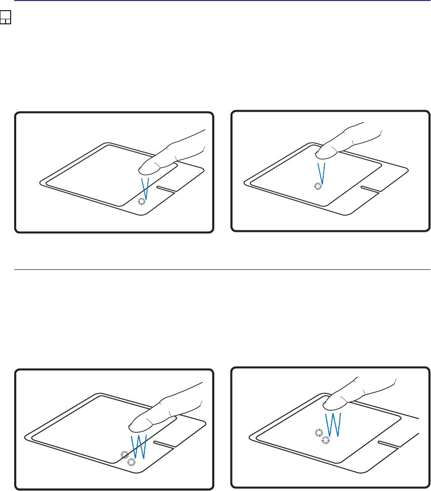
Double-clicking/Double-tapping - This is a common skill for launching a program directly from the
corresponding icon you select. Move the cursor over the icon you wish to execute, press the left button or
tap the pad twice in rapid succession, and the system launches the corresponding program. If the interval
between the clicks or taps is too long, the operation will not be executed. You can set the double-click speed
using the Windows Control Panel “Mouse.” The following 2 examples produce the same results.
Press the left button twice and release. Lightly but rapidly strike the touchpad twice.
Press the left cursor button and release. Lightly but rapidly strike the touchpad.
Clicking/Tapping -:LWKWKHFXUVRURYHUDQLWHPSUHVVWKHOHIWEXWWRQRUXVH\RXUÀQJHUWLSWRWRXFKWKH
WRXFKSDGOLJKWO\NHHSLQJ\RXUÀQJHURQWKHWRXFKSDGXQWLOWKHLWHPLVVHOHFWHG7KHVHOHFWHGLWHPZLOO
change color. The following 2 examples produce the same results.
Clicking Tapping
Double-Clicking Double-Tapping
Touchpad Usage Illustrations
39
Using the Notebook PC 4
Caring for the Touchpad
The touchpad is pressure sensitive. If not properly cared for, it can be easily damaged. Take note of the
following precautions.
• Make sure the touchpad does not come into contact with dirt, liquids or grease.
'RQRWWRXFKWKHWRXFKSDGLI\RXUÀQJHUVDUHGLUW\RUZHW
'RQRWUHVWKHDY\REMHFWVRQWKHWRXFKSDGRUWKHWRXFKSDGEXWWRQV
'RQRWVFUDWFKWKHWRXFKSDGZLWK\RXUÀQJHUQDLOVRUDQ\KDUGREMHFWV
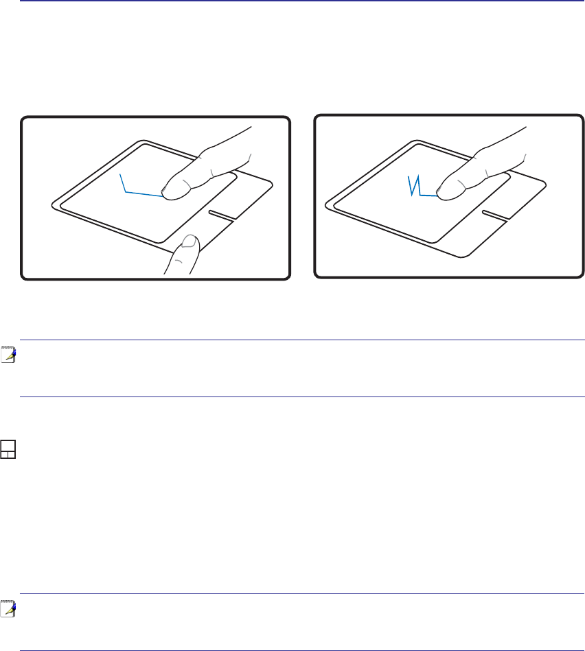
Dragging -'UDJJLQJPHDQVWRSLFNXSDQLWHPDQGSODFHLWDQ\ZKHUHRQWKHVFUHHQ\RXZLVK<RXFDQ
move the cursor over the item you select, and while keeping the left button depressed, moving the cursor
to the desired location, then release the button. Or, you can simply double-tap on the item and hold while
GUDJJLQJWKHLWHPZLWK\RXUÀQJHUWLS7KHIROORZLQJLOOXVWUDWLRQVSURGXFHWKHVDPHUHVXOWV
+ROGOHIWEXWWRQDQGVOLGHÀQJHURQWRXFKSDG /LJKWO\VWULNHWKHWRXFKSDGWZLFHVOLGLQJÀQJHURQ
touchpad during second strike.
Dragging-Clicking Dragging-Tapping
NOTE: A software-controlled scrolling function is available after setting up the included
touchpad utility to allow easy Windows or web navigation. Basic functions can be
adjusted at the Windows control panel to allow comfortable clicking and tapping.
NOTE: The touchpad responds to movement not to force. There is no need to tap
the surface too hard. Tapping too hard does not increase the responsiveness of the
touchpad. The touchpad responds best to light pressure.
40
4 Using the Notebook PC
Storage Devices
6WRUDJHGHYLFHVDOORZWKH1RWHERRN3&WRUHDGRUZULWHGRFXPHQWVSLFWXUHVDQGRWKHUÀOHVWRYDULRXV
data storage devices. This Notebook PC has the following storage devices:
• Expansion Card
• Optical drive
• Flash memory reader
• Hard disk drive
Expansion Card
One 26pin Express card slot is available to support one ExpressCard/34mm or one
ExpressCard/54mm expansion card. This new interface is faster by using a serial bus
supporting USB 2.0 and PCI Express instead of the slower parallel bus used in the PC
card slot. (Not compatible with previous PCMCIA cards.)
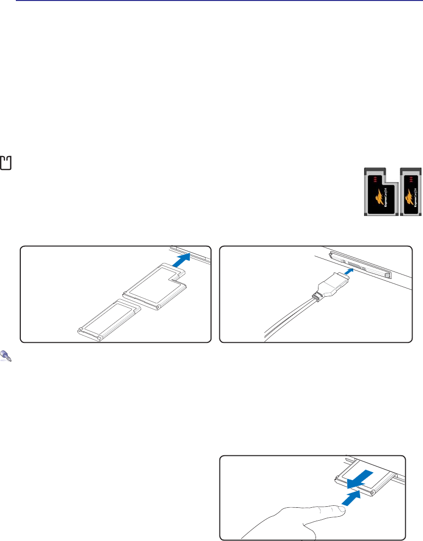
Inserting an Expansion Card
Be sure the ExpressCard
is level when inserting.
1. If there is an ExpressCard socket protector,
remove it using the “Removing an Express-
Card” instructions below.
2. Insert the ExpressCard with the connector side
ÀUVWDQGODEHOVLGHXS6WDQGDUG([SUHVV&DUGV
ZLOOEHÁXVKZLWKWKH1RWHERRN3&ZKHQIXOO\
inserted.
3. Carefully connect any cables or adapters
needed by the ExpressCard. Usually connectors
can only be inserted in one orientation. Look
for a sticker, icon, or marking on one side of
the connector representing the top side.
Removing an Expansion Card
The ExpressCard slot does not have an eject but-
ton. Press the ExpressCard inwards and release to
eject the ExpressCard. Carefully pull the ejected
ExpressCard out of the socket.
41
Using the Notebook PC 4
Optical Drive
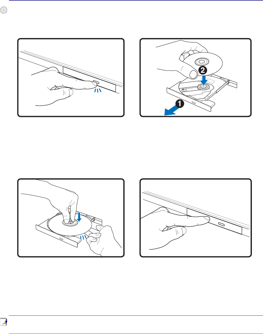
Inserting an optical disc
1. While the Notebook PC’s power is ON, press
the drive’s eject button and the tray will eject
out partially.
2. Gently pull on the drive’s front panel and slide
the tray completely out. Be careful not to touch
WKH&'GULYHOHQVDQGRWKHUPHFKDQLVPV0DNH
sure there are no obstructions that may get
jammed under the drive’s tray.
3. Hold the disc by the edge and face the disc’s
printed side up. Push down on both sides of
the disc’s center until the disc snaps onto the
hub. The hub should be higher than the
disc when correctly mounted.
4. Slowly push the drive’s tray back in. The drive
will begin reading the table of contents (TOC)
on the disc. When the drive stops, the disc is
ready to be used.
NOTE: It is normal to hear as well as feel the CD spinning with great intensity in the
CD drive while data is read.
42
4 Using the Notebook PC
$&'GULYHOHWWHUVKRXOGEHSUHVHQWUHJDUGOHVVRIWKHSUHVHQFHRID&'GLVFLQWKHGULYH$IWHUWKH&'LV
properly inserted, data can be accessed just like with hard disk drives; except that nothing can be written
WRRUFKDQJHGRQWKH&'8VLQJWKHSURSHUVRIWZDUHD&'5:GULYHRU'9'&'5:GULYHFDQDOORZ
&'5:GLVFVWREHXVHGOLNHDKDUGGULYHZLWKZULWLQJGHOHWLQJDQGHGLWLQJFDSDELOLWLHV
9LEUDWLRQLVQRUPDOIRUDOOKLJKVSHHGRSWLFDOGULYHVGXHWRXQEDODQFHG&'VRU&'SULQW7RGHFUHDVH
YLEUDWLRQXVHWKH1RWHERRN3&RQDQHYHQVXUIDFHDQGGRQRWSODFHODEHOVRQWKH&'
Listening to Audio CD
7KHRSWLFDOGULYHVFDQSOD\DXGLR&'VEXWRQO\WKH'9'520GULYHFDQSOD\'9'DXGLR,QVHUWWKH
DXGLR&'DQG:LQGRZVDXWRPDWLFDOO\RSHQVDQDXGLRSOD\HUDQGEHJLQVSOD\LQJ'HSHQGLQJRQWKH
'9'DXGLRGLVFDQGLQVWDOOHGVRIWZDUHLWPD\UHTXLUHWKDW\RXRSHQD'9'SOD\HUWROLVWHQWR'9'
audio. You can adjust the volume using hotkeys or Windows™ speaker icon on the taskbar.
Using the Optical Drive
Optical discs and equipment must be handled with care because of the precise mechanics involved.
.HHSLQPLQGWKHLPSRUWDQWVDIHW\LQVWUXFWLRQVIURP\RXU&'VXSSOLHUV8QOLNHGHVNWRSRSWLFDOGULYHV
WKH1RWHERRN3&XVHVDKXEWRKROGWKH&'LQSODFHUHJDUGOHVVRIWKHDQJOH:KHQLQVHUWLQJD&'LWLV
LPSRUWDQWWKDWWKH&'EHSUHVVHGRQWRWKHFHQWHUKXERUHOVHWKHRSWLFDOGULYHWUD\ZLOOVFUDWFKWKH&'
WARNING! If the CD disc is not properly locked onto the center hub, the CD can be
damaged when the tray is closed. Always watch the CD closely while closing the tray
slowly to prevent damage.
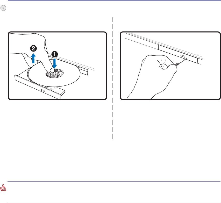
Eject the tray and gently pry the edge of the disc
upwards at an angle to remove the disc from
the hub.
The emergency eject is located in a hole on the op-
tical drive and is used to eject the optical drive tray
LQFDVHWKHHOHFWURQLFHMHFWGRHVQRWZRUN'RQRW
use the emergency eject in place of the electronic
eject. Note: Make sure not to stab the activity
indicator located in the same area.
Actual location will
vary by model.
Optical Drive (Cont.)
Emergency eject
Removing an optical disc
43
Using the Notebook PC 4
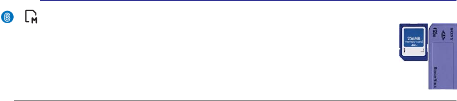
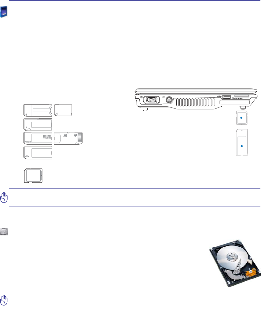
MS (Memory Stick)
Duo/Pro/Duo Pro/MG
MS (Memory Stick)
Select
MS (Memory Stick)
Magic Gate (MG)
MS (Memory Stick)
MS adapter
MMC (Multimedia Card)
SD (Secure Digital)
Supported Memory Types
IMPORTANT! Never remove cards while or immediately after reading, copying, format-
ting, or deleting data on the card or else data loss may occur.
SD / MMC
MS / MS Pro
512MB
Flash Memory Card Reader
Normally a PCMCIA memory card reader must be purchased separately in order to use memory cards
IURPGHYLFHVVXFKDVGLJLWDOFDPHUDV03SOD\HUVPRELOHSKRQHVDQG3'$V7KLV1RWHERRN3&KDV
DVLQJOHEXLOWLQPHPRU\FDUGUHDGHUWKDWFDQUHDGWKHIROORZLQJÁDVKPHPRU\FDUGV6HFXUH'LJLWDO
6' 0XOWL0HGLD &DUG 00& 0HPRU\ 6WLFN 06 0HPRU\ 6WLFN 6HOHFW 06 6HOHFW 0HPRU\
6WLFN'XRZLWK06DGDSWHU0HPRU\6WLFN3URDQG0HPRU\6WLFN3UR'XRZLWK063URDGDSWHU
Memory Sticks may be standard or with MagicGate technology. The built-in memory card reader is not
only convenient, but also faster than most other forms of memory card readers because it utilizes the
high-bandwidth PCI bus.
Hard Disk Drive
Hard disk drives have higher capacities and operate at much faster speeds than
ÁRSS\GLVNGULYHVDQGRSWLFDOGULYHV7KH1RWHERRN3&FRPHVZLWKDUHSODFH-
able 2.5” (6.35cm) wide and approximately .374” (.95cm) high hard disk drive.
Current hard drives support S.M.A.R.T. (Self Monitoring and Reporting Technol-
ogy) to detect hard disk errors or failures before they happen. When replacing or
upgrading the hard drive, always visit an authorized service center or retailer for
this Notebook PC.
IMPORTANT! Poor handling of the Notebook PC may damage the hard disk drive.
Handle the Notebook PC gently and keep it away from static electricity and strong
vibrations or impact. The hard disk drive is the most delicate component and will
OLNHO\EHWKHÀUVWRURQO\FRPSRQHQWWKDWLVGDPDJHGLIWKH1RWHERRN3&LVGURSSHG
44
4 Using the Notebook PC
NOTE: The built-in modem and network cannot be installed later as an upgrade. After
purchase, modem and/or network can be installed as an expansion card.
CAUTION: For electrical safety concerns, only use telephone cables rated 26AWG or
higher. (see Glossary for more information)
NOTE: When you are connected to an online service, do not place the Notebook PC
in suspend (or sleep mode) or else you will disconnect the modem connection.
Connections
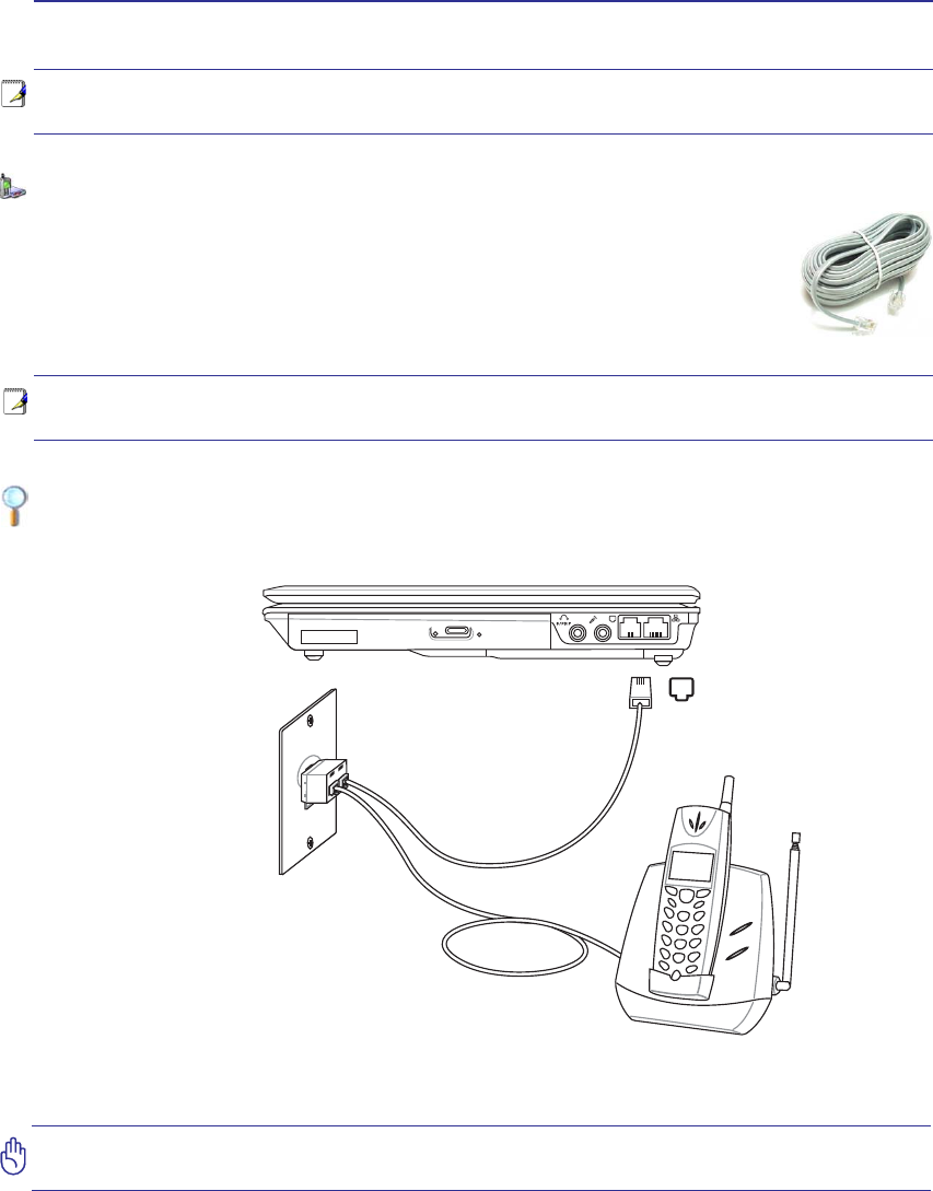
Example of the Notebook PC connected to a telephone jack for use with the built-in modem:
Modem Connection
The telephone wire used to connect the Notebook PC’s internal modem should have
either two or four wires (only two wires (telephone line #1) is used by the modem) and
should have an RJ-11 connector on both ends. Connect one end to the modem port and
the other end to an analog telephone wall socket (the ones found in residential buildings).
Once the driver is setup, the modem is ready to use.
Telephone Wall
Jack
Telephone cables
with RJ-11 connectors
Telephone
connection is
optional
Telephone connector
is the smaller of the two.
45
Using the Notebook PC 4
WARNING! Only use analog telephone outlets. The built-in modem does not support
the voltage used in digital phone systems. Do not connect the RJ-11 to digital phone
systems found in many commercial buildings or else damage will occur!
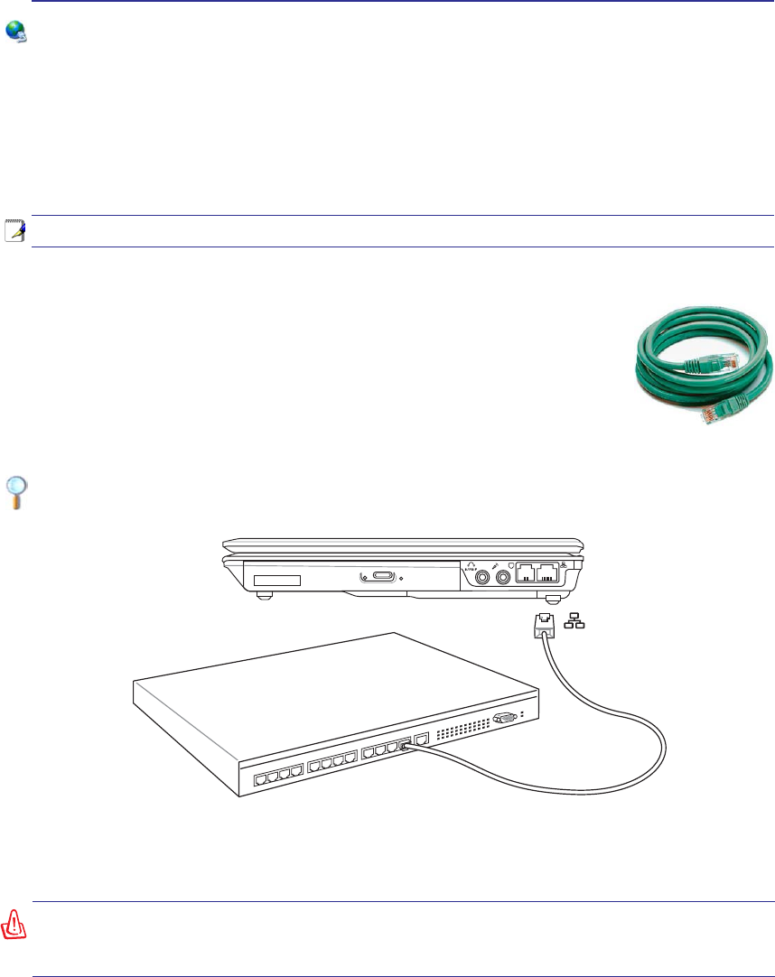
Example of the Notebook PC connected to a Network Hub or Switch for use with the built-in
Ethernet controller.
Network Connection
Connect a network cable, with RJ-45 connectors on each end, to the modem/network port on the Note-
book PC and the other end to a hub or switch. For 100 BASE-TX / 1000 BASE-T speeds, your network
cable must be category 5 or better (not category 3) with twisted-pair wiring. If you plan on running the
interface at 100/1000Mbps, it must be connected to a 100 BASE-TX / 1000 BASE-T hub (not a BASE-T4
KXE)RU%DVH7XVHFDWHJRU\RUWZLVWHGSDLUZLULQJ0ESV)XOO'XSOH[LVVXSSRUWHG
on this Notebook PC but requires connection to a network switching hub with “duplex” enabled. The
software default is to use the fastest setting so no user-intervention is required.
1000BASE-T (or Gigabit) is only supported on selected models.
Twisted-Pair Cable
The cable used to connect the Ethernet card to a host (generally a Hub or Switch)
is called a straight-through Twisted Pair Ethernet (TPE). The end connectors are
called RJ-45 connectors, which are not compatible with RJ-11 telephone connectors.
If connecting two computers together without a hub in between, a crossover LAN
cable is required (Fast-Ethernet model). (Gigabit models support auto-crossover so
a crossover LAN cable is optional.)
Network Hub or Switch
Network cable with RJ-45 connectors
LAN
connector is the
larger of the two.
46
4 Using the Notebook PC
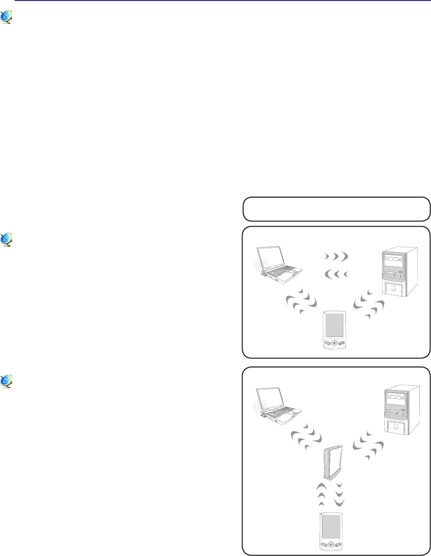
These are examples of the Notebook PC
connected to a Wireless Network.
Desktop PC
PDA
Notebook PC
Access
Point
Desktop PC
PDA
Notebook PC
Wireless LAN Connection (on selected models)
The optional built-in wireless LAN is a compact easy-to-use wireless Ethernet adapter. Implementing
the IEEE 802.11 standard for wireless LAN (WLAN), the optional built-in wireless LAN is capable of
IDVWGDWDWUDQVPLVVLRQUDWHVXVLQJ'LUHFW6HTXHQFH6SUHDG6SHFWUXP'666DQG2UWKRJRQDO)UHTXHQF\
'LYLVLRQ0XOWLSOH[LQJ2)'0WHFKQRORJLHVRQ*+]*+]IUHTXHQFLHV7KHRSWLRQDOEXLOWLQZLUH-
less LAN is backward compatible with the earlier IEEE 802.11 standards allowing seamless interfacing
of wireless LAN standards.
The optional built-in wireless LAN is a client adapter that supports Infrastructure and Ad-hoc modes
JLYLQJ\RXÁH[LELOLW\RQ\RXUH[LVWLQJRUIXWXUHZLUHOHVVQHWZRUNFRQÀJXUDWLRQVIRUGLVWDQFHVXSWR
meters between the client and the access point.
7RSURYLGHHIÀFLHQWVHFXULW\WR\RXUZLUHOHVVFRPPXQLFDWLRQWKHRSWLRQDOEXLOWLQZLUHOHVV/$1FRPHV
with a 64-bit/128-bit Wired Equivalent Privacy (WEP) encryption and Wi-Fi Protected Access (WPA)
features.
Ad-hoc mode
The Ad-hoc mode allows the Notebook PC to connect
to another wireless device. No access point (AP) is
required in this wireless environment.
(All devices must install optional 802.11 wireless LAN adapters.)
Infrastructure mode
The Infrastructure mode allows the Notebook PC and
other wireless devices to join a wireless network cre-
ated by an Access Point (AP) (sold separately) that
provides a central link for wireless clients to commu-
nicate with each other or with a wired network.
(All devices must install optional 802.11 wireless LAN adapters.)
47
Using the Notebook PC 4
1
2
3
4
5
6
7
*
#
8
0
9
g
p
t
j
a
d
m
?
w
+
a/A
ɕ
əɪ
ɣɧ
ɲɶ
ɥɩ
ɴɸ
ɦɵ
ɹ
ɤɨ
ɳɷ
ɝɠɮ
ɞɡɯ
ɖ
ɚɫ
ɟɢ
ɰɱ
ɗ
ɬɛ
ɜ
ɘɭ
Bluetooth Wireless Connection (on selected models)
Notebook PCs with Bluetooth technology eliminates the need for cables for connecting Blue-
WRRWKHQDEOHGGHYLFHV([DPSOHVRI%OXHWRRWKHQDEOHGGHYLFHVPD\EH1RWHERRN3&V'HVNWRS
3&VPRELOHSKRQHVDQG3'$V
Note: If your Notebook PC did not come with built-in Bluetooth, you need to connect
a USB or ExpressCard Bluetooth module in order to use Bluetooth.
Bluetooth-enabled mobile phones
<RXFDQZLUHOHVVFRQQHFWWR\RXUPRELOHSKRQH'HSHQGLQJRQ\RXUPRELOHSKRQH·VFD-
SDELOLWLHV\RXFDQWUDQVIHUSKRQHERRNGDWDSKRWRVVRXQGÀOHVHWFRUXVHLWDVDPRGHP
to connect to the Internet. You may also use it for SMS messaging.
Bluetooth-enabled computers or PDAs
<RXFDQZLUHOHVVFRQQHFWWRDQRWKHUFRPSXWHURU3'$DQGH[FKDQJHÀOHVVKDUHSHULSKHUDOV
or share Internet or network connections. You may also make use of Bluetooth-enabled
wireless keyboard or mouse.
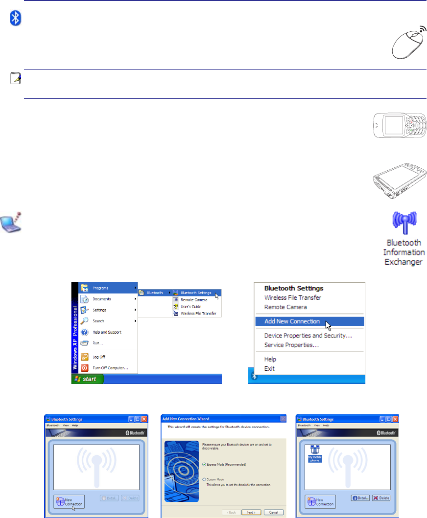
Pairing with Bluetooth-enabled devices
<RXÀUVWQHHGWRSDLU\RXU1RWHERRN3&ZLWKD%OXHWRRWKHQDEOHGGHYLFHEHIRUH\RXFDQ
connect to it. Make sure the Bluetooth-enabled device is turned ON and ready to accept a
pair. Launch Bluetooth Settings from Windows Start | Programs | Bluetooth or select
Add New Connection from the Bluetooth taskbar icon if available.
Add New Connection from the
Bluetooth taskbar icon
Bluetooth Settings from Windows Start |
Programs | Bluetooth
Click New Connection from
Bluetooth Settings. Follow the wizard to add Bluetooth
devices. After complete, you should see
your device in the window.

48
4 Using the Notebook PC
Power Management Modes
The Notebook PC has a number of automatic or adjustable power saving features that you can use to
maximize battery life and lower Total Cost of Ownership (TCO). You can control some of these features
through the Power menu in the BIOS Setup. ACPI power management settings are made through the
operating system. The power management features are designed to save as much electricity as possible
by putting components into a low power consumption mode as often as possible but also allow full
operation on demand. These low power modes are referred to as “Stand by” (or Suspend-to-RAM) and
´+LEHUQDWLRQµPRGHRU6XVSHQGWR'LVN67'7KH6WDQGE\PRGHLVDVLPSOHIXQFWLRQSURYLGHGE\WKH
operating system. When the Notebook PC is in either one of the power saving modes, the status will be
VKRZQE\WKHIROORZLQJ´6WDQGE\µ3RZHU/('%OLQNVDQG´+LEHUQDWLRQµ3RZHU/('2))
Full Power Mode & Maximum Performance
The Notebook PC operates in Full Power mode when the power management function is disabled by
FRQÀJXULQJ:LQGRZVSRZHUPDQDJHPHQWDQG6SHHG6WHS:KHQWKH1RWHERRN3&LVRSHUDWLQJLQ)XOO
3RZHU0RGHWKH3RZHU/('UHPDLQV21,I\RXDUHFRQVFLRXVRIERWKV\VWHPSHUIRUPDQFHDQGSRZHU
consumption, select “Maximum Performance” instead of disabling all power management features.
ACPI
$GYDQFHG&RQÀJXUDWLRQDQG3RZHU0DQDJHPHQW$&3,ZDVGHYHORSHGE\,QWHO0LFURVRIWDQG7RVKLED
especially for Windows and later to control power management and Plug and Play features. ACPI is the
new standard in power management for Notebook PCs.
NOTE: APM was used in older operating systems like Windows NT4 and Windows 98.
Because newer operating systems like Windows XP, Windows 2000, and Windows ME
utilize ACPI, APM is no longer fully supported on this Notebook PC.
Suspend Mode
,Q´6WDQGE\µ675DQG´+LEHUQDWLRQµ67'WKH&38FORFNLVVWRSSHGDQGPRVWRIWKH1RWHERRN3&
devices are put in their lowest active state. The suspend mode is the lowest power state of the Notebook
3&7KH1RWHERRN3&HQWHUVVXVSHQGPRGHZKHQWKHV\VWHPUHPDLQVLGOHIRUDVSHFLÀHGDPRXQWRIWLPH
RUPDQXDOO\XVLQJWKH>)Q@>)@NH\V7KH3RZHU/('EOLQNVZKHQWKH1RWHERRN3&LVLQ675PRGH
,Q67'PRGHWKH1RWHERRN3&ZLOODSSHDUWREHSRZHUHG2))5HFRYHUIURP675E\SUHVVLQJDQ\
NH\ERDUGEXWWRQH[FHSW)Q5HFRYHUIURP67'E\XVLQJWKHSRZHUVZLWFKMXVWOLNHSRZHULQJ21WKH
Notebook PC).
Power Savings
,QDGGLWLRQWRUHGXFLQJWKH&38FORFNWKLVPRGHSXWVGHYLFHVLQFOXGLQJWKH/&'EDFNOLJKWLQWKHLUORZHU
active state. The Notebook PC enters “Stand by” mode (low priority) when the system remains idle for a
VSHFLÀHGDPRXQWRIWLPH7KHWLPHRXWFDQEHVHWWKURXJK:LQGRZVSRZHUPDQDJHPHQWKLJKHUSULRULW\
To resume system operation, press any key.

49
Using the Notebook PC 4
Thermal Power Control
There are three power control methods for controlling the Notebook PC’s thermal state. These power
FRQWUROFDQQRWEHFRQÀJXUHGE\WKHXVHUDQGVKRXOGEHNQRZQLQFDVHWKH1RWHERRN3&VKRXOGHQWHU
these states. The following temperatures represent the chassis temperature (not CPU).
• The fan turns ON for active cooling when the temperature reaches the safe upper limit.
• The CPU decreases speed for passive cooling when the temperature exceeds the safe upper limit.
• The system shut down for critical cooling when temperature exceeds the maximum safe upper
limit.
Power State Summary
STATE ENTRY EVENT EXIT EVENT
“Stand by” • “Stand by” through Windows Start button
• Timer as set though “Power Management” in
Windows Control Panel (higher priority)
• Any device
• Battery low
STR (“Stand by”)
(Suspend-to-RAM) • Hotkey (see “Colored Hotkeys” under “Special
Keyboard Functions” in the previous section) • Signal from modem port
• Power button or any key
STD (“Hibernate”)
(Suspend-to-Disk) • Hotkey (see “Colored Hotkeys” under “Special
Keyboard Functions” in the previous section) • Power button
Soft OFF 3RZHUEXWWRQFDQEHGHÀQHGDV675RU67'
• “Shut down” through Windows Start button • Power button
50
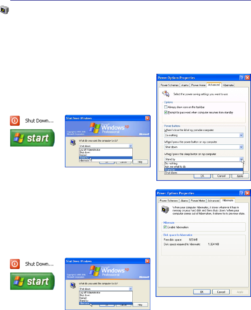
4 Using the Notebook PC
“Stand by” is the same as Suspend-to-RAM (STR). This
function stores your current data and status in RAM while
many components are turned OFF. Because RAM is volatile,
it requires power to keep (refresh) the data. To operate: select
“Start” | “Shut down”, and “Stand by”.
“Hibernate” LV WKH VDPH DV 6XVSHQGWR'LVN 67' DQG
stores your current data and status on the hard disk drive. By
doing this, RAM does not have to be periodically refreshed
and power consumption is greatly reduced but not completely
eliminated because certain wake-up components like LAN
needs to remain powered. “Hibernate” saves more power
compared to “Stand by”. To operate: Enable hibernation
in “Power Options” and select “Start” | “Shut down”, and
“Hibernate”.
Stand by and Hibernate
Power management settings can be found in the Windows control panel. The following shows the power
RSWLRQVSURSHUWLHVLQ:LQGRZV<RXFDQGHÀQH´6WDQG%\µRU´6KXWGRZQµIRUFORVLQJWKHGLVSOD\SDQHO
pressing the power button, or activating sleep mode. “Stand by” and “Hibernate” saves power when
your Notebook PC is not in use by turning OFF certain components. When you resume your work, your
last status (such as a document scrolled down half way or email typed half way) will reappear as if you
never left. “Shut down” will close all applications and ask if you want to save your work if any are not
saved.

51
Appendix
Optional Accessories
Optional Connections
Glossary
Declarations and Safety Statements
Notebook PC Information
52
A Appendix
Optional Accessories
These items, if desired, come as optional items to complement your Notebook PC.
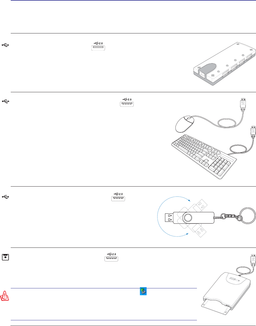
USB Flash Memory Disk
$ 86% ÁDVK PHPRU\ GLVN LV DQ RSWLRQDO LWHP WKDW FDQ
UHSODFH WKH 0% ÁRSS\ GLVN DQG SURYLGH VWRUDJH XS
to several hundred megabytes, higher transfer speeds, and
greater durability. When used in current operating systems,
no drivers are necessary.
USB Hub (Optional)
Attaching an optional USB hub will increase your USB ports and allow
you to quickly connect or disconnect many USB peripherals through a
single cable.
WARNING! To prevent system failures, use (Safely Remove
+DUGZDUHRQWKHWDVNEDUEHIRUHGLVFRQQHFWLQJWKH86%ÁRSS\
GLVNGULYH(MHFWWKHÁRSS\GLVNEHIRUHWUDQVSRUWLQJWKH1RWHERRN
PC to prevent damage from shock.
USB Floppy Disk Drive
$QRSWLRQDO86%LQWHUIDFHÁRSS\GLVNGULYHFDQDFFHSWDVWDQGDUG0%RU
.%LQFKÁRSS\GLVNHWWH
USB Keyboard and Mouse
Attaching an external USB keyboard will allow data entry to be
more comfortable. Attaching an external USB mouse will allow
Windows navigation to be more comfortable. Both the external
USB keyboard and mouse will work simultaneously with the
Notebook PC’s built-in keyboard and touchpad.
53
Appendix A
Optional Connections
These items, if desired, may be purchased from third-parties.
Printer Connection
One or more USB printers can be simultaneously used on any USB port
or USB hub.

54
A Appendix
Glossary
$&3,$GYDQFHG&RQÀJXUDWLRQDQG3RZHU0DQDJHPHQW,QWHUIDFH
Modern standard for reducing power usage in computers.
APM (Advanced Power Management)
Modern standard for reducing power usage in computers.
AWG (American Wire Gauge)
NOTE: This table is for general reference only and should not be used as a source of
the American Wire Gauge standard as this table may not be current or complete.
Gauge Diam Area R I@3A/mm2
AWG (mm) (mm2) (ohm/km) (mA)
33 0.18 0.026 676 75
0.19 0.028 605 85
32 0.20 0.031 547 93
30 0.25 0.049 351 147
29 0.30 0.071 243 212
27 0.35 0.096 178 288
26 0.40 0.13 137 378
25 0.45 0.16 108 477
Gauge Diam Area R I@3A/mm2
AWG (mm) (mm2) (ohm/km) (mA)
24 0.50 0.20 87.5 588
0.55 0.24 72.3 715
0.60 0.28 60.7 850
22 0.65 0.33 51.7 1.0 A
0.70 0.39 44.6 1.16 A
0.75 0.44 38.9 1.32 A
20 0.80 0.50 34.1 1.51 A
0.85 0.57 30.2 1.70 A
BIOS (Basic Input/Output System)
BIOS is a set of routines that affect how the computer transfers data between computer components, such
as memory, disks, and the display adapter. The BIOS instructions are built into the computer’s read-only
PHPRU\%,26SDUDPHWHUVFDQEHFRQÀJXUHGE\WKHXVHUWKURXJKWKH%,266HWXSSURJUDP7KH%,26
FDQEHXSGDWHGXVLQJWKHSURYLGHGXWLOLW\WRFRS\DQHZ%,26ÀOHLQWRWKH((3520
Bit (Binary Digit)
Represents the smallest unit of data used by the computer. A bit can have one of two values: 0 or 1.
Boot
Boot means to start the computer operating system by loading it into system memory. When the manual
instructs you to “boot” your system (or computer), it means to turn ON your computer. “Reboot” means
WRUHVWDUW\RXUFRPSXWHU:KHQXVLQJ:LQGRZVRUODWHUVHOHFWLQJ´5HVWDUWµIURP´6WDUW_6KXW'RZQµ
will reboot your computer.
Byte (Binary Term)
One byte is a group of eight contiguous bits. A byte is used to represent a single alphanumeric character,
punctuation mark, or other symbol.

55
Appendix A
Clock Throttling
Chipset function which allows the processor’s clock to be stopped and started at a known duty cycle.
Clock throttling is used for power savings, thermal management, and reducing processing speed.
CPU (Central Processing Unit)
The CPU, sometimes called “Processor,” actually functions as the “brain” of the computer. It interprets
and executes program commands and processes data stored in memory.
Device Driver
A device driver is a special set of instructions that allows the computer’s operating system to communicate
with devices such as VGA, audio, Ethernet, printer, or modem.
DVD
'9'LVHVVHQWLDOO\DELJJHUIDVWHU&'WKDWFDQKROGYLGHRDVZHOODVDXGLRDQGFRPSXWHUGDWD:LWKWKHVH
FDSDFLWLHVDQGDFFHVVUDWHV'9'GLVFVFDQSURYLGH\RXZLWKGUDPDWLFDOO\HQKDQFHGKLJKFRORUIXOOPR-
WLRQYLGHRVEHWWHUJUDSKLFVVKDUSHUSLFWXUHVDQGGLJLWDODXGLRIRUDWKHDWHUOLNHH[SHULHQFH'9'DLPV
to encompass home entertainment, computers, and business information with a single digital format,
HYHQWXDOO\UHSODFLQJDXGLR&'YLGHRWDSHODVHUGLVF&'520DQGYLGHRJDPHFDUWULGJHV
ExpressCard
ExpressCard slot is 26 pins and support one ExpressCard/34mm or one ExpressCard/54mm expansion
card. This new interface is faster by using a serial bus supporting USB 2.0 and PCI Express instead of
the slower parallel bus used in the PC card slot. (Not compatible with previous PCMCIA cards.)
Hardware
Hardware is a general term referring to the physical components of a computer system, including pe-
ripherals such as printers, modems, and pointing devices.
IDE (Integrated Drive Electronics)
,'(GHYLFHVLQWHJUDWHWKHGULYHFRQWUROFLUFXLWU\GLUHFWO\RQWKHGULYHLWVHOIHOLPLQDWLQJWKHQHHGIRUD
VHSDUDWHDGDSWHUFDUGLQWKHFDVHIRU6&6,GHYLFHV8OWUD'0$RU,'(GHYLFHVFDQDFKLHYHXS
to 33MB/Sec transfer.
IEEE1394 (1394)
Also known as iLINK (Sony) or FireWire (Apple). 1394 is a high speed serial bus like SCSI but has
simple connections and hot-plugging capabilities like USB. The popular 1394a interface has a bandwidth
of 400Mbits/sec and can handle up to 63 units on the same bus. The newer 1394b interface can support
twice the speed and will appear in future models when peripherals support higher speeds. It is very likely
WKDWWRJHWKHUZLWK86%ZLOOUHSODFH3DUDOOHO,'(6&6,DQG(,'(SRUWVLVDOVRXVHGLQ
KLJKHQGGLJLWDOHTXLSPHQWDQGVKRXOGEHPDUNHG´'9µIRU'LJLWDO9LGHRSRUW
Infrared Port (IrDA) (on selected models)
7KHLQIUDUHG,U'$FRPPXQLFDWLRQSRUWDOORZVFRQYHQLHQWZLUHOHVVGDWDFRPPXQLFDWLRQZLWKLQIUD-
red-equipped devices or computers up to 4Mbits/sec. This allows easy wireless synchronization with
3'$VRUPRELOHSKRQHVDQGHYHQZLUHOHVVSULQWLQJWRSULQWHUV6PDOORIÀFHVFDQXVH,U'$WHFKQRORJ\WR
VKDUHDSULQWHUEHWZHHQVHYHUDOFORVHO\SODFHG1RWHERRN3&VDQGHYHQVHQGÀOHVWRHDFKRWKHUZLWKRXW
a network.

56
A Appendix
Kensington® Locks
Kensington® locks (or compatible) allow the Notebook PC to be secured usually using a metal cable and
ORFNWKDWSUHYHQWWKH1RWHERRN3&WREHUHPRYHGIURPDÀ[HGREMHFW6RPHVHFXULW\SURGXFWVPD\DOVR
include a motion detector to sound an alarm when moved.
/DVHU&ODVVLÀFDWLRQV
As lasers became more numerous and more widely used, the need to warn users of laser hazards became
DSSDUHQW7RPHHWWKLVQHHGODVHUFODVVLÀFDWLRQVZHUHHVWDEOLVKHG&XUUHQWFODVVLÀFDWLRQOHYHOVYDU\IURP
optically safe, requiring no controls (Class 1) to very hazardous, requiring strict controls (Class 4).
CLASS 1: A Class 1 laser or laser system emits levels of optical energy that are eye-safe and consequently
require no controls. An example of this class of laser system is the checkout scanning device found
in most grocery stores or lasers used in optical drives.
CLASS 2 & CLASS 3A: Class 2 and Class 3A lasers emit visible, continuous-wave (CW) optical ra-
diation levels slightly above the maximum permissible exposure (MPE) level. Although these lasers
can cause eye damage, their brightness usually causes observers to look away or blink before eye
damage occurs. These lasers have strict administrative controls requiring placement of signs warning
personnel not to stare directly into the beam. Class 3A lasers must not be viewed with optically-aided
devices.
CLASS 3B: Class 3B lasers, and Class 3A lasers with outputs of 2.5mW, are hazardous to personnel
ZKRDUHZLWKLQWKHEHDPSDWKDQGORRNDWWKHEHDPVRXUFHGLUHFWO\RUE\VSHFXODUUHÁHFWLRQ7KHVH
ODVHUVFDQQRWSURGXFHKD]DUGRXVGLIIXVHUHÁHFWLRQV3HUVRQQHOZRUNLQJZLWKWKHVHODVHUVVKRXOGZHDU
appropriate protective eyewear during any operation of the laser. Class 3B lasers have both administra-
tive and physical controls to protect personnel. Physical controls include limited access work areas.
Administrative controls include special warning signs posted outside the entrances to the laser work
spaces and lights outside the entrances that warn personnel when the lasers are in use.
CLASS 4: Class 4 lasers are high-power lasers that will cause damage to unprotected eyes and skin
WKURXJKLQWUDEHDPYLHZLQJDQGVSHFXODURUGLIIXVHUHÁHFWLRQV&RQVHTXHQWO\QRSHUVRQQHOVKRXOG
be in a room where a Class 4 laser is operating without proper eye protection.
PCI Bus (Peripheral Component Interconnect Local Bus)
3&,EXVLVDVSHFLÀFDWLRQWKDWGHÀQHVDELWGDWDEXVLQWHUIDFH3&,LVDVWDQGDUGZLGHO\XVHGE\H[-
pansion card manufacturers.
POST (Power On Self Test)
:KHQ\RXWXUQRQWKHFRPSXWHULWZLOOÀUVWUXQWKURXJKWKH3267DVHULHVRIVRIWZDUHFRQWUROOHGGLDJ-
nostic tests. The POST checks system memory, the motherboard circuitry, the display, the keyboard, the
diskette drive, and other I/O devices.

57
Appendix A
RAM (Random Access Memory)
RAM (usually just called memory) is the place in a computer where the operating system, applica-
tion programs, and data in current use are temporarily kept so that they can be quickly reached by the
computer’s processor instead of having to read from and write to slower storage such as the hard disk
or optical disc.
Suspend Mode
,Q6DYHWR5$0675DQG6DYHWR'LVN67'WKH&38FORFNLVVWRSSHGDQGPRVWRIWKH1RWHERRN3&
devices are put in their lowest active state. The Notebook PC enters Suspend when the system remains
LGOHIRUDVSHFLÀHGDPRXQWRIWLPHRUPDQXDOO\XVLQJWKHIXQFWLRQNH\V7KHWLPHRXWVHWWLQJRIERWK
+DUG'LVNDQG9LGHRFDQEHVHWE\WKH%,266HWXS7KH3RZHU/('EOLQNVZKHQWKH1RWHERRN3&LV
LQ675PRGH,Q67'PRGHWKH1RWHERRN3&ZLOODSSHDUWREHSRZHUHG2))
System Disk
$V\VWHPGLVNFRQWDLQVWKHFRUHÀOHRIDQRSHUDWLQJV\VWHPDQGLVXVHGWRERRWXSWKHRSHUDWLQJV\VWHP
TPM (Trusted Platform Module) (on selected models)
The TPM is a security hardware device on the system board that will hold computer-generated keys for
encryption. It is a hardware-based solution that can help avoid attacks by hackers looking to capture
passwords and encryption keys to sensitive data. The TPM provides the ability to the PC or Notebook
PC to run applications more secure and to make transactions and communication more trustworthy.
Twisted-Pair Cable
The cable used to connect the Ethernet card to a host (generally a Hub or Switch) is called a straight-
through Twisted Pair Ethernet (TPE). The end connectors are called RJ-45 connectors, which are not
compatible with RJ-11 telephone connectors. If connecting two computers together without a hub in
between, a crossover twisted-pair is required.
UltraDMA/66 or 100
8OWUD'0$RUDUHQHZVSHFLÀFDWLRQVWRLPSURYH,'(WUDQVIHUUDWHV8QOLNHWUDGLWLRQDO3,2PRGH
ZKLFKRQO\XVHVWKHULVLQJHGJHRI,'(FRPPDQGVLJQDOWRWUDQVIHUGDWD8OWUD'0$RUXVHVERWK
rising edge and falling edge.
USB (Universal Serial Bus)
A new 4-pin serial peripheral bus that allows plug and play computer peripherals such as keyboard,
PRXVHMR\VWLFNVFDQQHUSULQWHUDQGPRGHP,6'1WREHDXWRPDWLFDOO\FRQÀJXUHGZKHQWKH\DUHDW-
tached physically without having to install drivers or reboot. With USB, the traditional complex cables
from back panel of your PC can be eliminated.

58
A Appendix
Declarations and Safety Statements
DVD-ROM Drive Information
7KH1RWHERRN3&FRPHVZLWKDQRSWLRQDO'9'520GULYHRUD&'520GULYH,QRUGHUWRYLHZ'9'
WLWOHV\RXPXVWLQVWDOO\RXURZQ'9'YLHZHUVRIWZDUH2SWLRQDO'9'YLHZHUVRIWZDUHPD\EHSXUFKDVHG
ZLWKWKLV1RWHERRN3&7KH'9'520GULYHDOORZVWKHXVHRIERWK&'DQG'9'GLVFV
Regional Playback Information
3OD\EDFNRI'9'PRYLHWLWOHVLQYROYHVGHFRGLQJ03(*YLGHRGLJLWDO$&DXGLRDQGGHFU\SWLRQRI&66
protected content. CSS (sometimes called copy guard) is the name given to the content protection scheme
adopted by the motion picture industry to satisfy a need to protect against unlawful content duplication.
Although the design rules imposed on CSS licensors are many, one rule that is most relevant is playback re-
VWULFWLRQVRQUHJLRQDOL]HGFRQWHQW,QRUGHUWRIDFLOLWDWHJHRJUDSKLFDOO\VWDJJHUHGPRYLHUHOHDVHV'9'YLGHR
WLWOHVDUHUHOHDVHGIRUVSHFLÀFJHRJUDSKLFUHJLRQVDVGHÀQHGLQ´5HJLRQ'HÀQLWLRQVµEHORZ&RS\ULJKWODZV
UHTXLUHWKDWDOO'9'PRYLHVEHOLPLWHGWRDSDUWLFXODUUHJLRQXVXDOO\FRGHGWRWKHUHJLRQDWZKLFKLWLVVROG
:KLOH'9'PRYLHFRQWHQWPD\EHUHOHDVHGIRUPXOWLSOHUHJLRQV&66GHVLJQUXOHVUHTXLUHWKDWDQ\V\VWHP
capable of playing CSS encrypted content must only be capable of playing one region.
5HJLRQ'HÀQLWLRQV
Region 1
Canada, US, US Territories
Region 2
Czech, Egypt, Finland, France, Germany, Gulf States, Hungary, Iceland, Iran, Iraq, Ireland, Italy, Japan,
Netherlands, Norway, Poland, Portugal, Saudi Arabia, Scotland, South Africa, Spain, Sweden, Switzer-
land, Syria, Turkey, UK, Greece, Former Yugoslav Republics, Slovakia
Region 3
Burma, Indonesia, South Korea, Malaysia, Philippines, Singapore, Taiwan, Thailand, Vietnam
Region 4
$XVWUDOLD&DULEEHDQ ([FHSW867HUULWRULHV&HQWUDO$PHULFD 1HZ=HDODQG 3DFLÀF,VODQGV 6RXWK
America
Region 5
CIS, India, Pakistan, Rest of Africa, Russia, North Korea
Region 6
China
127(7KHUHJLRQVHWWLQJPD\EHFKDQJHGXSWRÀYHWLPHVXVLQJWKHYLHZHUVRIWZDUH
then it can only play DVD movies for the last region setting. Changing the region code
after that will require factory resetting which is not covered by warranty. If resetting is
desired, shipping and resetting costs will be at the expense of the user.

59
Appendix A
Internal Modem Compliancy
The Notebook PC with internal modem model complies with JATE (Japan), FCC (US, Canada, Korea,
7DLZDQ DQG&757KH LQWHUQDO PRGHPKDV EHHQDSSURYHG LQDFFRUGDQFH ZLWK &RXQFLO'HFLVLRQ
98/482/EC for pan-European single terminal connection to the public switched telephone network
(PSTN). However due to differences between the individual PSTNs provided in different countries, the
approval does not, of itself, give an unconditional assurance of successful operation on every PSTN
network termination point. In the event of problems you should contact your equipment supplier in the
ÀUVWLQVWDQFH
Overview
2QWK$XJXVWWKH(XURSHDQ&RXQFLO'HFLVLRQUHJDUGLQJWKH&75KDVEHHQSXEOLVKHGLQWKH
2IÀFLDO-RXUQDORIWKH(&7KH&75DSSOLHVWRDOOQRQYRLFHWHUPLQDOHTXLSPHQWZLWK'70)GLDOOLQJ
which is intended to be connected to the analogue PSTN (Public Switched Telephone Network).
CTR 21 (Common Technical Regulation) for the attachment requirements for connection to the analogue
public switched telephone networks of terminal equipment (excluding terminal equipment supporting
WKHYRLFHWHOHSKRQ\MXVWLÀHGFDVHVHUYLFHLQZKLFKQHWZRUNDGGUHVVLQJLISURYLGHGLVE\PHDQVRIGXDO
tone multifrequency signalling.
Network Compatibility Declaration
6WDWHPHQWWREHPDGHE\WKHPDQXIDFWXUHUWRWKH1RWLÀHG%RG\DQGWKHYHQGRU´7KLVGHFODUDWLRQZLOO
LQGLFDWHWKHQHWZRUNVZLWKZKLFKWKHHTXLSPHQWLVGHVLJQHGWRZRUNDQGDQ\QRWLÀHGQHWZRUNVZLWK
ZKLFKWKHHTXLSPHQWPD\KDYHLQWHUZRUNLQJGLIÀFXOWLHVµ
Network Compatibility Declaration
Statement to be made by the manufacturer to the user: “This declaration will indicate the networks with
ZKLFKWKHHTXLSPHQWLVGHVLJQHGWRZRUNDQG DQ\QRWLÀHGQHWZRUNVZLWKZKLFKWKHHTXLSPHQWPD\
KDYHLQWHUZRUNLQJGLIÀFXOWLHV7KHPDQXIDFWXUHUVKDOODOVRDVVRFLDWHDVWDWHPHQWWRPDNHLWFOHDUZKHUH
network compatibility is dependent on physical and software switch settings. It will also advise the user
to contact the vendor if it is desired to use the equipment on another network.”
8SWRQRZWKH1RWLÀHG%RG\RI&(7(&20LVVXHGVHYHUDOSDQ(XURSHDQDSSURYDOVXVLQJ&757KH
UHVXOWVDUH(XURSH·VÀUVWPRGHPVZKLFKGRQRWUHTXLUHUHJXODWRU\DSSURYDOVLQHDFKLQGLYLGXDO(XURSHDQ
country.
Non-Voice Equipment
Answering machines and loud-speaking telephones can be eligible as well as modems, fax machines,
auto-dialers and alarm systems. Equipment in which the end-to-end quality of speech is controlled by
regulations (e.g. handset telephones and in some countries also cordless telephones) is excluded.

60
A Appendix
Internal Modem Compliancy (Cont.)
This table shows the countries currently under the CTR21 standard
.
Country Applied More Testing
Austria1 Yes No
Belgium Yes No
Czech Republic No Not Applicable
'HQPDUN1 Yes Yes
Finland Yes No
France Yes No
Germany Yes No
Greece Yes No
Hungary No Not Applicable
Iceland Yes No
Ireland Yes No
Italy Still Pending Still Pending
Israel No No
Lichtenstein Yes No
Luxemburg Yes No
The Netherlands1Yes Yes
Norway Yes No
Poland No Not Applicable
Portugal No Not Applicable
Spain No Not Applicable
Sweden Yes No
Switzerland Yes No
United Kingdom Yes No
This information was copied from CETECOM and is supplied without liability. For updates to this table,
you may visit http://www.cetecom.de/technologies/ctr_21.html
1 National requirements will apply only if the equipment may use pulse dialling (manufacturers may state
LQWKHXVHUJXLGHWKDWWKHHTXLSPHQWLVRQO\LQWHQGHGWRVXSSRUW'70)VLJQDOOLQJZKLFKZRXOGPDNH
DQ\DGGLWLRQDOWHVWLQJVXSHUÁXRXV
,Q7KH1HWKHUODQGVDGGLWLRQDOWHVWLQJLVUHTXLUHGIRUVHULHVFRQQHFWLRQDQGFDOOHU,'IDFLOLWLHV

61
Appendix A
Federal Communications Commission Statement
This device complies with FCC Rules Part 15. Operation is subject to the following two conditions:
• This device may not cause harmful interference, and
• This device must accept any interference received, including interference that may cause undesired
operation.
This equipment has been tested and found to comply with the limits for a class B digital device, pursuant
to Part 15 of the Federal Communications Commission (FCC) rules. These limits are designed to provide
reasonable protection against harmful interference in a residential installation. This equipment generates,
uses, and can radiate radio frequency energy and, if not installed and used in accordance with the instructions,
may cause harmful interference to radio communications. However, there is no guarantee that interference
will not occur in a particular installation. If this equipment does cause harmful interference to radio or
television reception, which can be determined by turning the equipment off and on, the user is encouraged
to try to correct the interference by one or more of the following measures:
• Reorient or relocate the receiving antenna.
• Increase the separation between the equipment and receiver.
• Connect the equipment into an outlet on a circuit different from that to which the receiver is
connected.
• Consult the dealer or an experienced radio/TV technician for help.
WARNING! The use of a shielded-type power cord is required in order to meet FCC
emission limits and to prevent interference to the nearby radio and television recep-
tion. It is essential that only the supplied power cord be used. Use only shielded
cables to connect I/O devices to this equipment. You are cautioned that changes or
PRGLÀFDWLRQVQRWH[SUHVVO\DSSURYHGE\WKHSDUW\UHVSRQVLEOHIRUFRPSOLDQFHFRXOG
void your authority to operate the equipment.
5HSULQWHGIURPWKH&RGHRI)HGHUDO5HJXODWLRQVSDUW:DVKLQJWRQ'&2IÀFHRIWKH)HGHUDO
5HJLVWHU1DWLRQDO$UFKLYHVDQG5HFRUGV$GPLQLVWUDWLRQ86*RYHUQPHQW3ULQWLQJ2IÀFH
CE Mark Warning
This is a Class B product, in a domestic environment, this product may cause radio interference, in which
case the user may be required to take adequate measures.

62
A Appendix
R&TTE Directive (1999/5/EC)
7KHIROORZLQJLWHPVZHUHFRPSOHWHGDQGDUHFRQVLGHUHGUHOHYDQWDQGVXIÀFLHQWIRUWKH577(5DGLR
7HOHFRPPXQLFDWLRQV7HUPLQDO(TXLSPHQWGLUHFWLYH
(VVHQWLDOUHTXLUHPHQWVDVLQ>$UWLFOH@
3URWHFWLRQUHTXLUHPHQWVIRUKHDOWKDQGVDIHW\DVLQ>$UWLFOHD@
7HVWLQJIRUHOHFWULFVDIHW\DFFRUGLQJWR>(1@
3URWHFWLRQUHTXLUHPHQWVIRUHOHFWURPDJQHWLFFRPSDWLELOLW\LQ>$UWLFOHE@
7HVWLQJIRUHOHFWURPDJQHWLFFRPSDWLELOLW\LQ>(1@>(1@
7HVWLQJDFFRUGLQJWR>@
(IIHFWLYHXVHRIWKHUDGLRVSHFWUXPDVLQ>$UWLFOH@
5DGLRWHVWVXLWHVDFFRUGLQJWR>(1@
FCC Radio Frequency Interference Requirements
7KLVGHYLFHLVUHVWULFWHGWR,1'22586(GXHWRLWVRSHUDWLRQLQWKHWR*+]IUHTXHQF\UDQJH
FCC requires this product to be used indoors for the frequency range 5.15 to 5.25GHz to reduce the
potential for harmful interference to co-channel of the Mobile Satellite Systems.
IMPORTANT: This device and its antenna(s) must not be co-located or operating in
conjunction with any other antenna or transmitter.
FCC Radio Frequency (RF) Exposure Caution Statement
This equipment complies with FCC RF exposure limits set forth for an uncontrolled environment.
To maintain compliance with FCC RF exposure compliance requirements, please follow operation
instructions in the user’s manual. This equipment is for operation within 5.15 GHz and 5.25GHz frequency
ranges and is restricted to indoor environments only.
)&&&DXWLRQ$Q\FKDQJHVRUPRGLÀFDWLRQVQRWH[SUHVVO\DSSURYHGE\WKHSDUW\UH-
sponsible for compliance could void the user’s authority to operate this equipment.
“The manufacturer declares that this device is limited to Channels 1 through 11 in the
*+]IUHTXHQF\E\VSHFLÀHGÀUPZDUHFRQWUROOHGLQWKH86$µ
This equipm ent com plies with EU RF radiation exposure limits of 2 W/kg.
802.11b=0.342 W/kg, 802.11g=0.224W /kg, 802.11a (5200M H z)= 0.287W /kg,
802.11a (5800M H z)= 0.236W /kg

63
Appendix A
France Restricted Wireless Frequency Bands
Some areas of France have a restricted frequency band. The worst case maximum authorized power
indoors are:
• 10mW for the entire 2.4 GHz band (2400 MHz–2483.5 MHz)
• 100mW for frequencies between 2446.5 MHz and 2483.5 MHz
NOTE: Channels 10 through 13 inclusive operate in the band 2446.6 MHz to 2483.5 MHz.
There are few possibilities for outdoor use: On private property or on the private property of public
SHUVRQVXVHLVVXEMHFWWRDSUHOLPLQDU\DXWKRUL]DWLRQSURFHGXUHE\WKH0LQLVWU\RI'HIHQVHZLWKPD[LPXP
authorized power of 100mW in the 2446.5–2483.5 MHz band. Use outdoors on public property is not
permitted.
In the departments listed below, for the entire 2.4 GHz band:
• Maximum authorized power indoors is 100mW
• Maximum authorized power outdoors is 10mW
'HSDUWPHQWVLQZKLFKWKHXVHRIWKH²0+]EDQGLVSHUPLWWHGZLWKDQ(,53RIOHVVWKDQ
100mW indoors and less than 10mW outdoors:
01 Ain Orientales 02 Aisne 03 Allier 05 Hautes Alpes
08 Ardennes 09 Ariège 11 Aude 12 Aveyron
&KDUHQWH 'RUGRJQH 'RXEV 'U{PH
32 Gers 36 Indre 37 Indre et Loire 41 Loir et Cher
45 Loiret 50 Manche 55 Meuse 58 Nièvre
1RUG 2LVH 2UQH 3X\GX'{PH
64 Pyrénées Atlantique 66 Pyrénées 67 Bas Rhin 68 Haut Rhin
+DXWH6D{QH 6D{QHHW/RLUH 3DULV 7DUQHW*DURQQH
84 Vaucluse 88 Vosges 89 Yonne 90 Territoire de Belfort
94 Val de Marne
This requirement is likely to change over time, allowing you to use your wireless LAN card in more
areas within France. Please check with ART for the latest information (www.art-telecom.fr)
NOTE: Your WLAN Card transmits less than 100mW, but more than 10mW.
Wireless Operation Channel for Different Domains
N. America 2.412-2.462 GHz Ch01 through CH11
Japan 2.412-2.484 GHz Ch01 through Ch14
Europe ETSI 2.412-2.472 GHz Ch01 through Ch13

64
A Appendix
UL Safety Notices
Required for UL 1459 covering telecommunications (telephone) equipment intended to be electrically
connected to a telecommunication network that has an operating voltage to ground that does not exceed
200V peak, 300V peak-to-peak, and 105V rms, and installed or used in accordance with the National
Electrical Code (NFPA 70).
When using the Notebook PC modem, basic safety precautions should always be followed to reduce the
ULVNRIÀUHHOHFWULFVKRFNDQGLQMXU\WRSHUVRQVLQFOXGLQJWKHIROORZLQJ
•Do not use the Notebook PC near water, for example, near a bath tub, wash bowl, kitchen sink or
laundry tub, in a wet basement or near a swimming pool.
• Do not use the Notebook PC during an electrical storm. There may be a remote risk of electric shock
from lightning.
•Do not use the Notebook PC in the vicinity of a gas leak.
Required for UL 1642 covering primary (non-rechargeable) and secondary (rechargeable) lithium batter-
ies for use as power sources in products. These batteries contain metallic lithium, or a lithium alloy, or
a lithium ion, and may consist of a single electrochemical cell or two or more cells connected in series,
parallel, or both, that convert chemical energy into electrical energy by an irreversible or reversible
chemical reaction.
•Do not GLVSRVHWKH1RWHERRN3&EDWWHU\SDFNLQDÀUHDVWKH\PD\H[SORGH&KHFNZLWKORFDOFRGHV
IRUSRVVLEOHVSHFLDOGLVSRVDOLQVWUXFWLRQVWRUHGXFHWKHULVNRILQMXU\WRSHUVRQVGXHWRÀUHRUH[SOR-
sion.
•Do not use power adapters or batteries from other devices to reduce the risk of injury to persons due
WRÀUHRUH[SORVLRQ8VHRQO\8/FHUWLÀHGSRZHUDGDSWHUVRUEDWWHULHVVXSSOLHGE\WKHPDQXIDFWXUHU
or authorized retailers.
Power Safety Requirement
Products with electrical current ratings up to 6A and weighing more than 3Kg must use approved power
cords greater than or equal to: H05VV-F, 3G, 0.75mm2 or H05VV-F, 2G, 0.75mm2.
65
Appendix A
Nordic Lithium Cautions (for lithium-ion batteries)
CAUTION! 'DQJHURIH[SORVLRQLIEDWWHU\LVLQFRUUHFWO\UHSODFHG5HSODFHRQO\ZLWKWKHVDPHRUHTXLYD-
OHQWW\SHUHFRPPHQGHGE\WKHPDQXIDFWXUHU'LVSRVHRIXVHGEDWWHULHVDFFRUGLQJWRWKHPDQXIDFWXUHU·V
instructions. (English)
ATTENZIONE! Rischio di esplosione della batteria se sostituita in modo errato. Sostituire la batteria con
un una di tipo uguale o equivalente consigliata dalla fabbrica. Non disperdere le batterie nell’ambiente.
(Italian)
VORSICHT! Explosionsgetahr bei unsachgemäßen Austausch der Batterie. Ersatz nur durch denselben
oder einem vom Hersteller empfohlenem ähnlichen Typ. Entsorgung gebrauchter Batterien nach Angaben
des Herstellers. (German)
ADVARSELI! Lithiumbatteri - Eksplosionsfare ved fejlagtig håndtering. Udskiftning må kun ske med
EDWWHULDIVDPPHIDEULNDWRJW\SH/HYpUGHWEUXJWHEDWWHULWLOEDJHWLOOHYHUDQG¡UHQ'DQLVK
VARNING! Explosionsfara vid felaktigt batteribyte. Använd samma batterityp eller en ekvivalent typ som
rekommenderas av apparattillverkaren. Kassera använt batteri enligt fabrikantens instruktion. (Swedish)
VAROITUS! Paristo voi räjähtää, jos se on virheellisesti asennettu. Vaihda paristo ainoastaan laitevalmistajan
sousittelemaan tyyppiin. Hävitä käytetty paristo valmistagan ohjeiden mukaisesti. (Finnish)
ATTENTION! Il y a danger d’explosion s’il y a remplacement incorrect de la batterie. Remplacer
uniquement avec une batterie du mêre type ou d’un type équivalent recommandé par le constructeur.
Mettre au rebut les batteries usagées conformément aux instructions du fabricant. (French)
ADVARSEL! Eksplosjonsfare ved feilaktig skifte av batteri. Benytt samme batteritype eller en tilsvarende
type anbefalt av apparatfabrikanten. Brukte batterier kasseres i henhold til fabrikantens instruksjoner.
(Norwegian)
(Japanese)

66
A Appendix
Service warning label
:$51,1*0DNLQJDGMXVWPHQWVRUSHUIRUPLQJSURFHGXUHVRWKHUWKDQWKRVHVSHFLÀHG
in the user’s manual may result in hazardous laser exposure. Do not attempt to disas-
semble the optical drive. For your safety, have the optical drive serviced only by an
authorized service provider.
CAUTION: INVISIBLE LASER RADIATION WHEN OPEN. DO NOT STARE INTO BEAM
OR VIEW DIRECTLY WITH OPTICAL INSTRUMENTS.
CDRH Regulations
7KH&HQWHUIRU'HYLFHVDQG5DGLRORJLFDO+HDOWK&'5+RIWKH86)RRGDQG'UXJ$GPLQLVWUDWLRQLPSOH-
mented regulations for laser products on August 2, 1976. These regulations apply to laser products manu-
factured from August 1, 1976. Compliance is mandatory for products marketed in the United States.
WARNING: Use of controls or adjustments or performance of procedures other than
WKRVHVSHFLÀHGKHUHLQRULQWKHODVHUSURGXFWLQVWDOODWLRQJXLGHPD\UHVXOWLQKD]DUG-
ous radiation exposure.
Macrovision Corporation Product Notice
This product incorporates copyright protection technology that is protected by method claims of certain
U.S.A. patents and other intellectual property rights owned by Macrovision Corporation and other rights
owners. Use of this copyright protection technology must be authorized by Macrovision Corporation, and
is intended for home and other limited viewing uses only unless otherwise authorized by Macrovision
Corporation. Reverse engineering or disassembly is prohibited.
Optical Drive Safety Information
Laser Safety Information
,QWHUQDORUH[WHUQDORSWLFDOGULYHVVROGZLWKWKLV1RWHERRN3&FRQWDLQVD&/$66/$6(5352'8&7
/DVHUFODVVLÀFDWLRQVFDQEHIRXQGLQWKHJORVVDU\DWWKHHQGRIWKLVXVHU·VPDQXDO
67
Appendix A
Danish
Dutch
English
Finnish
French
German
Greek
Italian
Portuguese
Spanish
Swedish
CTR 21 Approval (for Notebook PC with built-in Modem)

68
A Appendix
Owner’s Name: ___________________________ Owner’s Telephone: ______________
Manufacturer:_______________ Model: ___________ Serial Number: ______________
Display Size: ___________Resolution: _____________Memory Size: ______________
Retailer: _________________Location: ___________ Purchase Date: ______________
Hard Drive Manufacturer: ____________________________ Capacity: ______________
Optical Drive Manufacturer: _____________________________ Type: ______________
BIOS Version:__________________________________________Date: ______________
Accessories: _____________________________________________________________
Accessories: _____________________________________________________________
Software
Operating System:__________Version: ___________ Serial Number: ______________
Software: _________________Version: ___________ Serial Number: ______________
Software: _________________Version: ___________ Serial Number: ______________
Security
Supervisor Name: _______________________ Supervisor Password: ______________
User Name:___________________________________User Password: ______________
Network
User Name:______________Password: _________________ Domain: ______________
User Name:______________Password: _________________ Domain: ______________
Notebook PC Information
This page is provided for recording information concerning your Notebook PC for future reference or
IRUWHFKQLFDOVXSSRUW.HHSWKLV8VHU·V0DQXDOLQDVHFXUHGORFDWLRQLISDVVZRUGVDUHÀOOHGRXW
Copyright Information
No part of this manual, including the products and software described in it, may be reproduced, trans-
mitted, transcribed, stored in a retrieval system, or translated into any language in any form or by any
means, except documentation kept by the purchaser for backup purposes, without the express written
permission of ASUSTeK COMPUTER INC. (“ASUS”).
$686 3529,'(6 7+,6 0$18$/ ´$6 ,6µ :,7+287 :$55$17< 2)$1< .,1' (,7+(5
(;35(6625,03/,(',1&/8',1*%87127/,0,7('727+(,03/,(':$55$17,(625
&21',7,2162)0(5&+$17$%,/,7<25),71(66)25$3$57,&8/$5385326(,112
(9(17 6+$//$686 ,76 ',5(&7256 2)),&(56 (03/2<((6 25$*(176 %( /,$%/(
)25$1<,1',5(&763(&,$/,1&,'(17$/25&216(48(17,$/'$0$*(6,1&/8',1*
'$0$*(6)25/2662)352),76/2662)%86,1(66/2662)86(25'$7$,17(5-
5837,212)%86,1(66$1'7+(/,.((9(1,)$686+$6%((1$'9,6('2)7+(326-
6,%,/,7<2)68&+'$0$*(6$5,6,1*)520$1<'()(&725(5525,17+,60$18$/
25352'8&7
Products and corporate names appearing in this manual may or may not be registered trademarks or
FRS\ULJKWVRIWKHLUUHVSHFWLYHFRPSDQLHVDQGDUHXVHGRQO\IRULGHQWLÀFDWLRQRUH[SODQDWLRQDQGWRWKH
RZQHUV·EHQHÀWZLWKRXWLQWHQWWRLQIULQJH
63(&,),&$7,216$1',1)250$7,21&217$,1(',17+,60$18$/$5()851,6+(')25
,1)250$7,21$/86(21/<$1'$5(68%-(&772&+$1*($7$1<7,0(:,7+28712-
7,&($1'6+28/'127%(&216758('$6$&200,70(17%<$686$686$6680(612
RESPONSIBILITY OR LIABILITY FOR ANY ERRORS OR INACCURACIES THAT MAY APPEAR
,17+,60$18$/,1&/8',1*7+(352'8&76$1'62)7:$5('(6&5,%(',1,7
Copyright © 2006 ASUSTeK COMPUTER INC. All Rights Reserved.
Limitation of Liability
Circumstances may arise where because of a default on ASUS’ part or other liability, you are entitled to
recover damages from ASUS. In each such instance, regardless of the basis on which you are entitled
to claim damages from ASUS, ASUS is liable for no more than damages for bodily injury (including
death) and damage to real property and tangible personal property; or any other actual and direct dam-
ages resulted from omission or failure of performing legal duties under this Warranty Statement, up to
the listed contract price of each product.
ASUS will only be responsible for or indemnify you for loss, damages or claims based in contract, tort
or infringement under this Warranty Statement.
This limit also applies to ASUS’ suppliers and its reseller. It is the maximum for which ASUS, its sup-
pliers, and your reseller are collectively responsible.
81'(512&,5&8067$1&(6,6$686/,$%/()25$1<2)7+()2//2:,1*7+,5'
3$57<&/$,06$*$,167<28)25'$0$*(6/2662)25'$0$*(72<2855(-
&25'625'$7$2563(&,$/,1&,'(17$/25,1',5(&7'$0$*(625)25$1<
(&2120,&&216(48(17,$/'$0$*(6,1&/8',1*/267352),76256$9,1*6(9(1
,)$686,766833/,(5625<2855(6(//(5,6,1)250('2)7+(,53266,%,/,7<
Service and Support
Visit our multi-language web site at http://support.asus.com