ASUSTeK Computer HSW1HEADSET Wireless Headset User Manual
ASUSTeK Computer Inc Wireless Headset
UserManual.wiki
>
ASUSTeK Computer
>
HSW1HEADSET User Manual
user manual
Navigation menu
Upload a User Manual
Namespaces
Wiki Guide
HTML
PDF
Info
Views
User Manual
Discussion / Help
Navigation
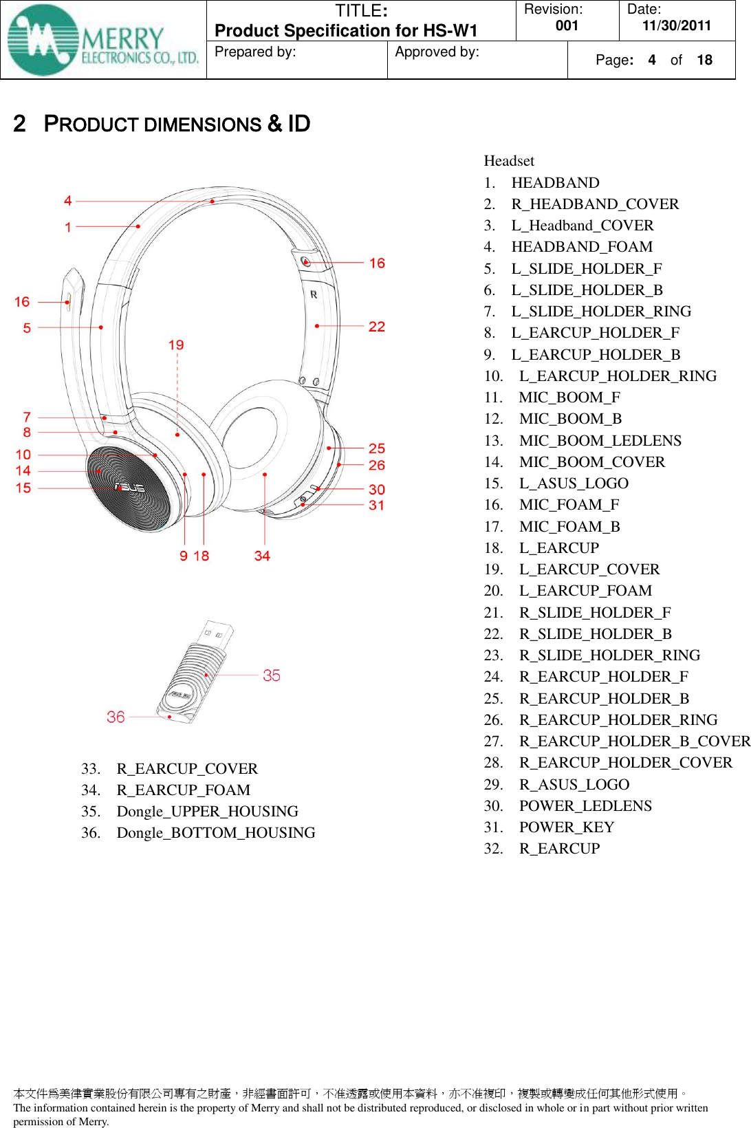
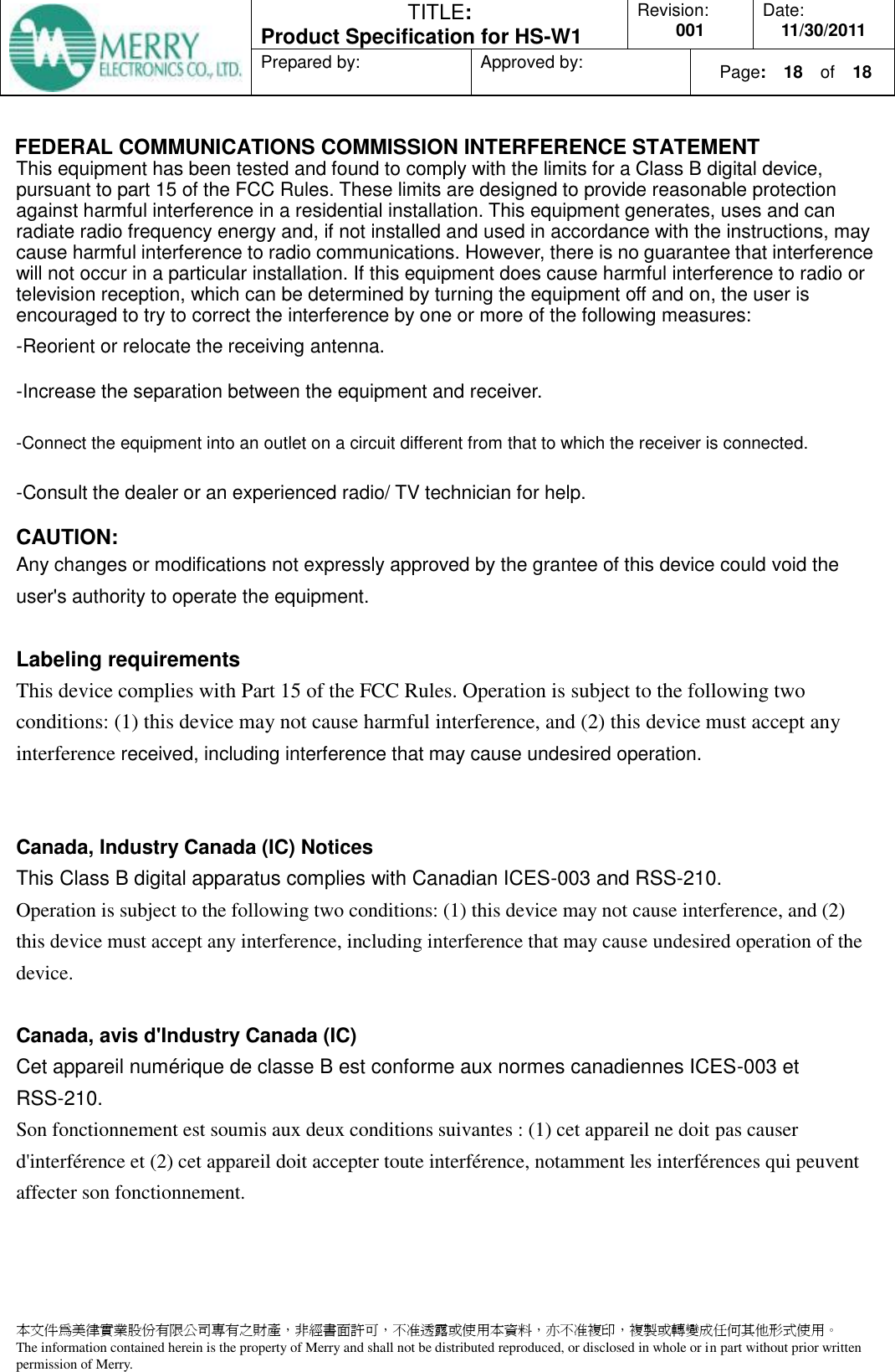
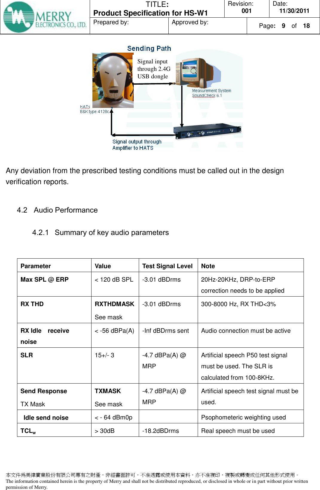
![TITLE: Product Specification for HS-W1 Revision: 001 Date: 11/30/2011 Prepared by: Approved by: Page: 7 of 18 本文件為美律實業股份有限公司專有之財產,非經書面許可,不准透露或使用本資料,亦不准複印,複製或轉變成任何其他形式使用。 The information contained herein is the property of Merry and shall not be distributed reproduced, or disclosed in whole or in part without prior written permission of Merry. 3.4.4 Current Consumption Operating Mode Mode Description Current Consumption (mA)(rms) from Battery Off Mode [X] Headset is not active. ≤ 0.05mA Standby Mode Headset is active, paired and connected to the phone. ≤ 50mA Playing Mode Headset is operating. ≤ 65mA Battery Life Time Playing music 6hr 3.5 Tone MMI Status Action Enter low battery mode Alert Tune beeps. MIC enable and disable Ring tone Power On Ring tone RF link Ring tone 3.6 RF Table 1 RF General Characteristics Parameter Minimum Typical Maximum Units Operating Frequency 2400 2525 MHz PLL Programming step 2 MHz System freauency 16 MHz Freauency deviation +/-700 KHz Channel spacing 2 MHz RF Transmitter Characteristics Maximum output power 6 8 dBm 20dB Bandwidth for modulated carrier 3 MHz First adjacent channel transmit power 2MHz -20 dBm Second adjacent channel transmit power 4MHz -50 dBm Maximum received signal at 0.1% BER 0 dBm Sensitivity(0.1% BER) -80 dBm RF Range 10 m](https://usermanual.wiki/ASUSTeK-Computer/HSW1HEADSET/User-Guide-1596758-Page-7.png)
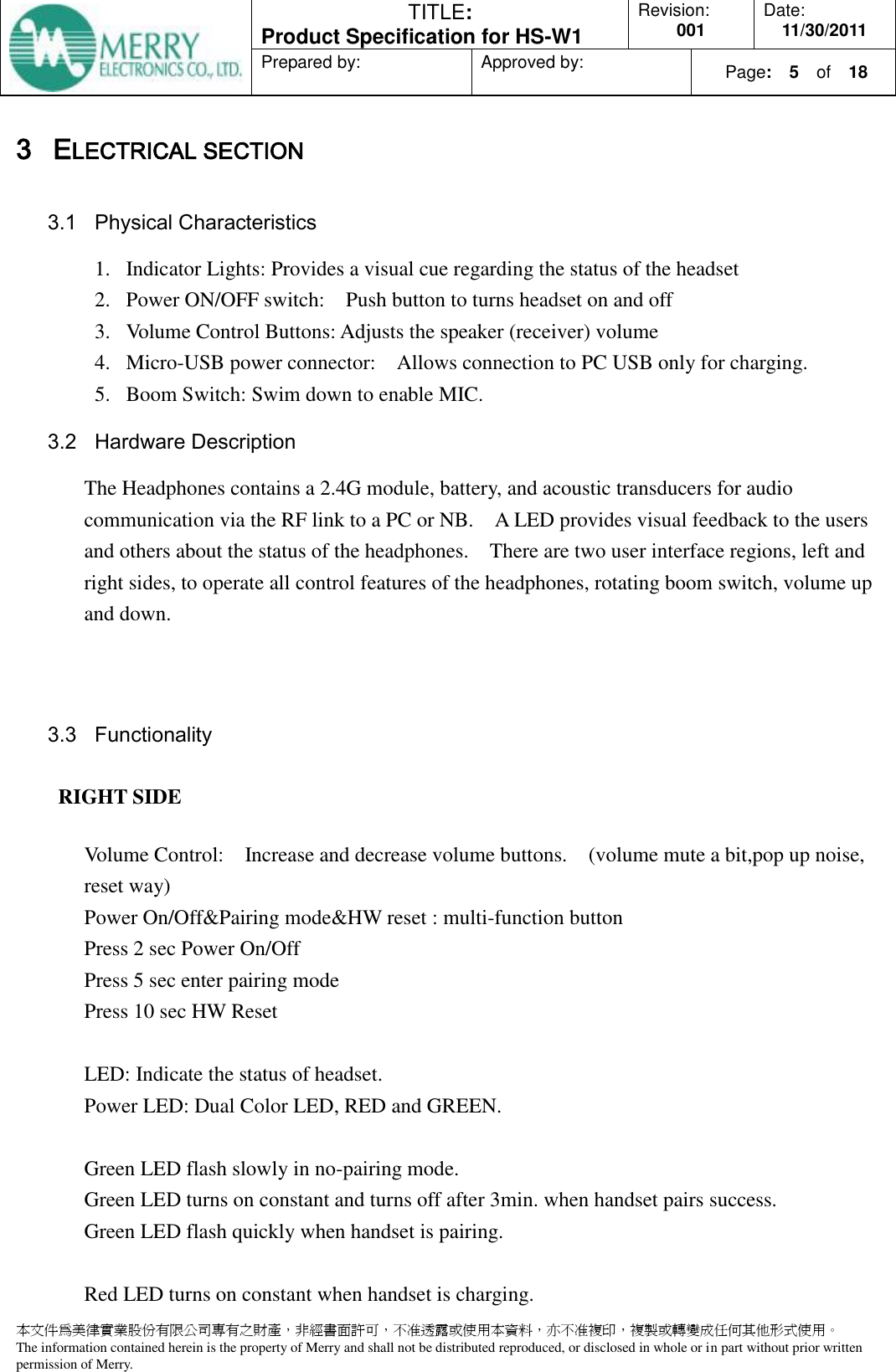
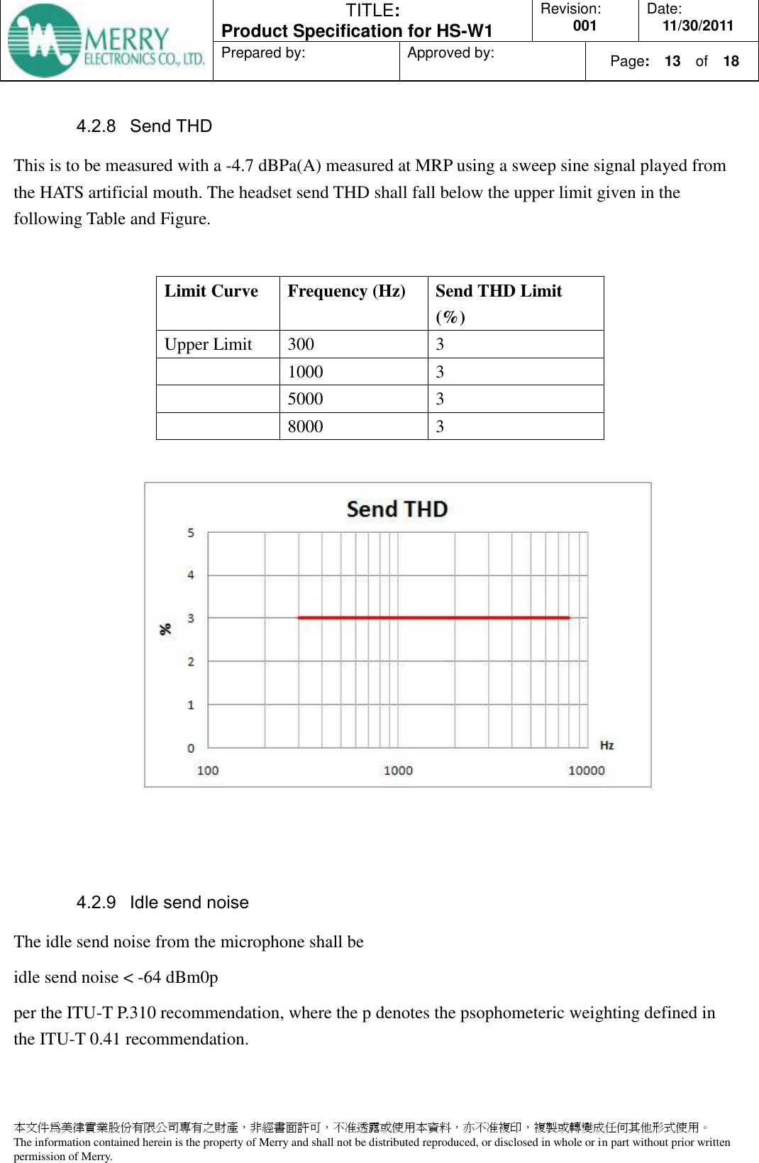
![TITLE: Product Specification for HS-W1 Revision: 001 Date: 11/30/2011 Prepared by: Approved by: Page: 10 of 18 本文件為美律實業股份有限公司專有之財產,非經書面許可,不准透露或使用本資料,亦不准複印,複製或轉變成任何其他形式使用。 The information contained herein is the property of Merry and shall not be distributed reproduced, or disclosed in whole or in part without prior written permission of Merry. 4.2.2 Max allowed SPL @ ERP This can be measured by sweeping a -3 dBDrms tone, and measuring the response from the IEC711 coupler. Note that the DRP-to-ERP correction is to be applied. No point on the curve is to be above 120 dB. 4.2.3 Receive THD The Receive THD shall be measured at the maximum volume step with a -3dBDrms sweep sine signal from 20Hz to 20KHz, and measuring the response from the IEC711 coupler. The headset Receive THD shall fall below the upper limit given in the following Table and Figure. Limit Curve Frequency (Hz) Send Response Limit (dB) [floating level] Upper Limit 300 3 1000 3 5000 3 8000 3](https://usermanual.wiki/ASUSTeK-Computer/HSW1HEADSET/User-Guide-1596758-Page-10.png)
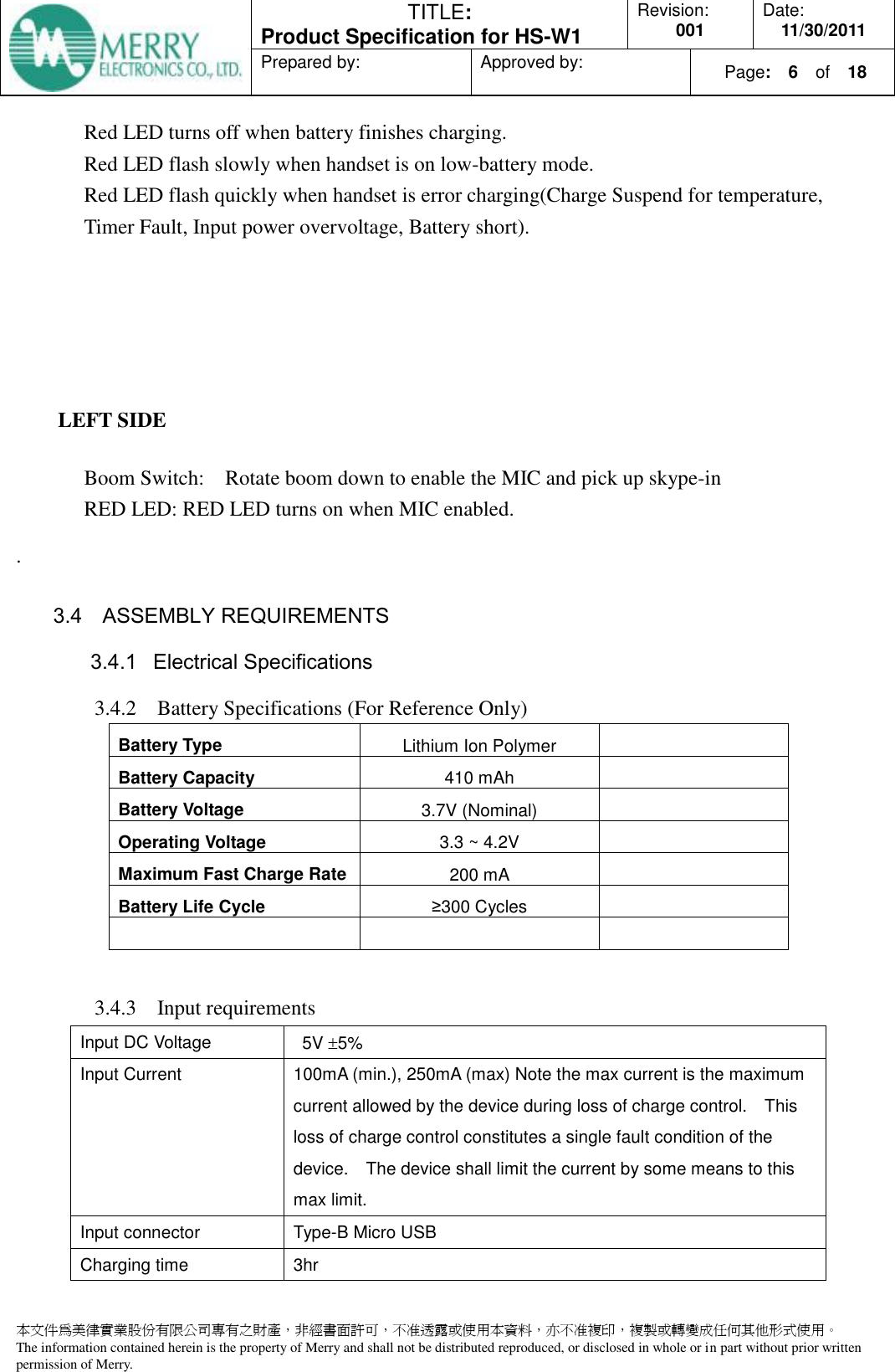
![TITLE: Product Specification for HS-W1 Revision: 001 Date: 11/30/2011 Prepared by: Approved by: Page: 11 of 18 本文件為美律實業股份有限公司專有之財產,非經書面許可,不准透露或使用本資料,亦不准複印,複製或轉變成任何其他形式使用。 The information contained herein is the property of Merry and shall not be distributed reproduced, or disclosed in whole or in part without prior written permission of Merry. 4.2.4 Idle receive noise (dBA) The idle receive noise shall be measured at the maximum volume step. This must be measured with a quite (all zero) signal being sent. The final ERP spectrum must be A weighted and power summed to achieve the final dBA value. Following the ITU-T p.310 recommendation, It shall not exceed -56 dBPa(A) or 38 dBA SPL measured on an IEC711 coupler with the DRP-to-ERP correction applied. 4.2.5 Send path The send microphone path is to be measured on a HATS with the send path representing the transfer function from the pressure at MRP to the microphone signal. Frequently in DSP enabled headsets, the send path cannot be measured with tones, but must be measured with a broadband artificial speech signal into the hats mouth simulator. The send path requirements are to be measured with an in-speech SPL of -4.7 dBPa(A) or 89.3 dBA SPL 3 dB at MRP. The signal sent into the artificial mouth must be equalized to compensate for the non-flat response of a HATS artificial mouth to achieve a nearly flat response between the digital representation of the test signal and the MRP pressure. 4.2.6 SLR The SLR is the loudness loss in the send direction from the acoustic signal at the mouth reference point to the send signal at the digital reference point. Refer to Annex A and ITU-T Recommendation P.79. The SLR shall be calculated using the 1/3rd octave sensitivity data collected from the send frequency response measurement. Use equation [A1] of Annex A and bands 1 to 20, of Table 14. The terminal is designed to have a SLR = 15 dB 3 dB 4.2.7 Send mask The headset send frequency response shall fall between the upper limit and the lower limit given in the following Table and Figure. The limit curves shall be determined by straight lines joining successive co-ordinates given in the table, when frequency response is plotted on a linear dB scale against frequency on a logarithmic scale. Note that the frequency response mask is a floating or “best fit” mask.](https://usermanual.wiki/ASUSTeK-Computer/HSW1HEADSET/User-Guide-1596758-Page-11.png)
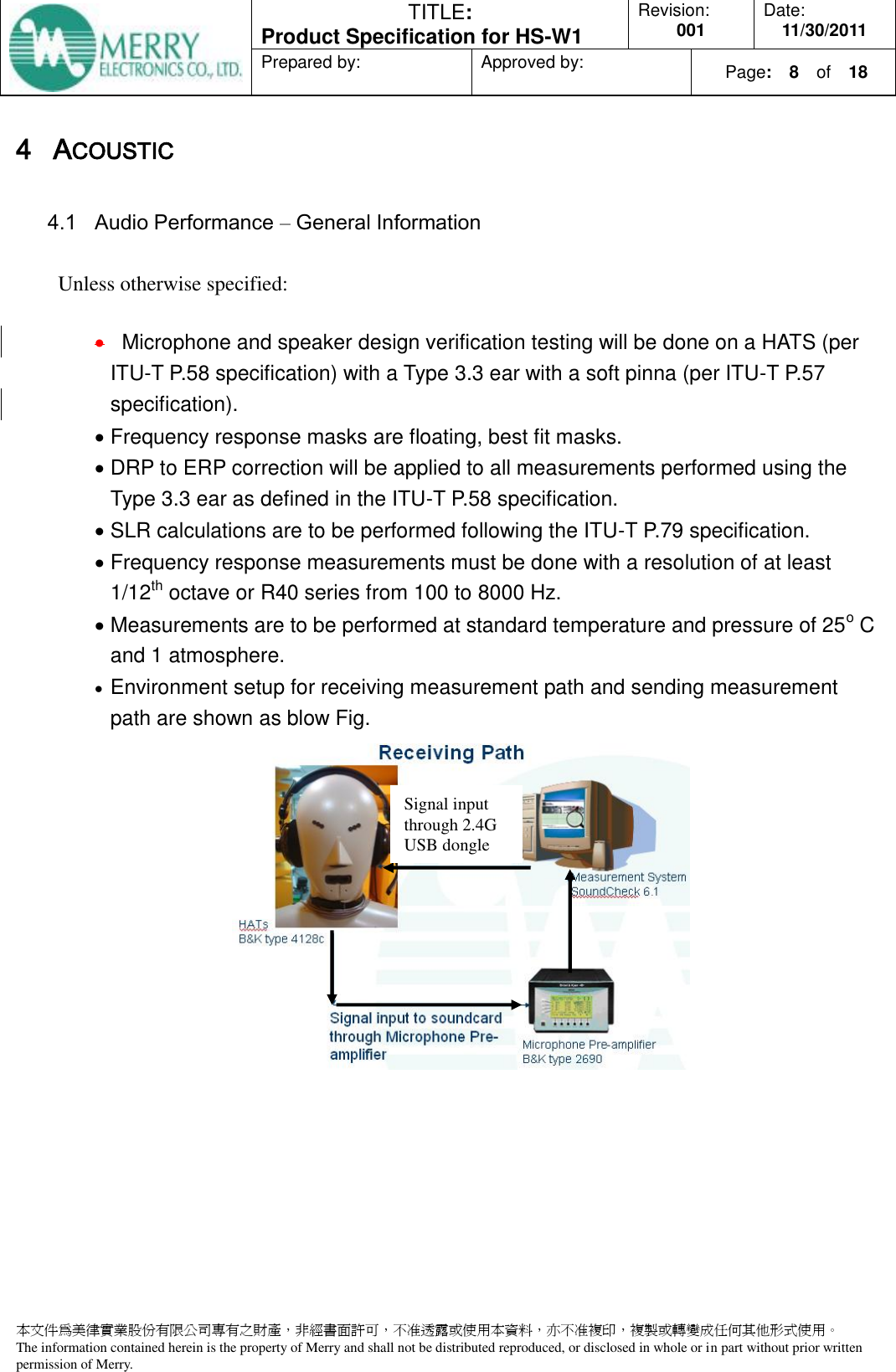
![TITLE: Product Specification for HS-W1 Revision: 001 Date: 11/30/2011 Prepared by: Approved by: Page: 12 of 18 本文件為美律實業股份有限公司專有之財產,非經書面許可,不准透露或使用本資料,亦不准複印,複製或轉變成任何其他形式使用。 The information contained herein is the property of Merry and shall not be distributed reproduced, or disclosed in whole or in part without prior written permission of Merry. Limit Curve Frequency (Hz) Send Response Limit (dB) [floating level] Upper Limit 100 0 1000 0 5000 4 8000 4 Lower Limit 200 -11 250 -8 5000 -8 6300 -11](https://usermanual.wiki/ASUSTeK-Computer/HSW1HEADSET/User-Guide-1596758-Page-12.png)
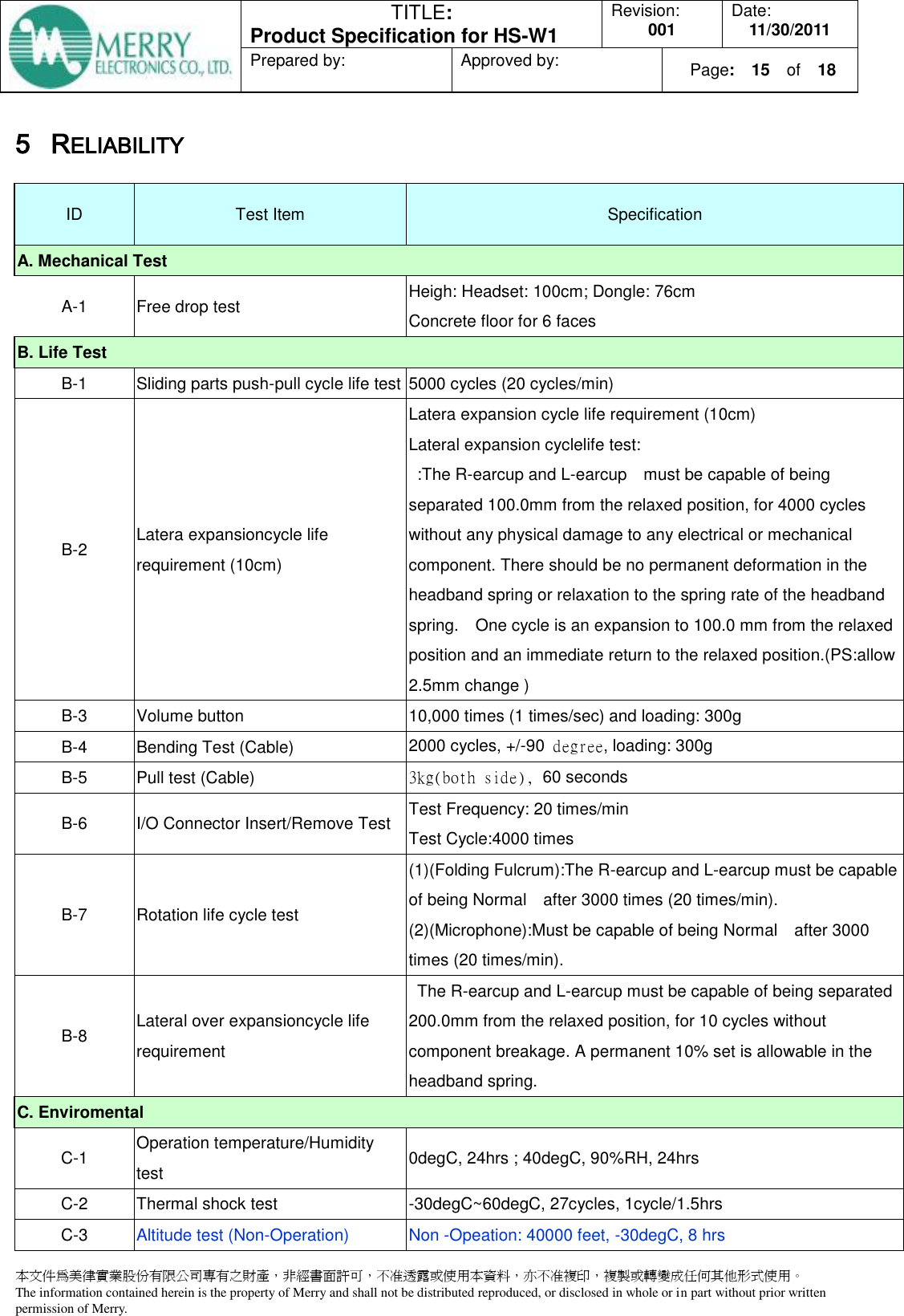
![TITLE: Product Specification for HS-W1 Revision: 001 Date: 11/30/2011 Prepared by: Approved by: Page: 14 of 18 本文件為美律實業股份有限公司專有之財產,非經書面許可,不准透露或使用本資料,亦不准複印,複製或轉變成任何其他形式使用。 The information contained herein is the property of Merry and shall not be distributed reproduced, or disclosed in whole or in part without prior written permission of Merry. 4.2.10 Echo performance The test signal level shall be -18.2 dBDrms. The TCLw is calculated according to ITU-T Recommendation G.122 [8], annex B, clause B.4 (trapezoidal rule). For the calculation the averaged measured echo level at each frequency band is referred to the averaged test signal level measured in each frequency band. The length of the test signal shall be at least one second (1,0 s). TCLW > 30 dB](https://usermanual.wiki/ASUSTeK-Computer/HSW1HEADSET/User-Guide-1596758-Page-14.png)
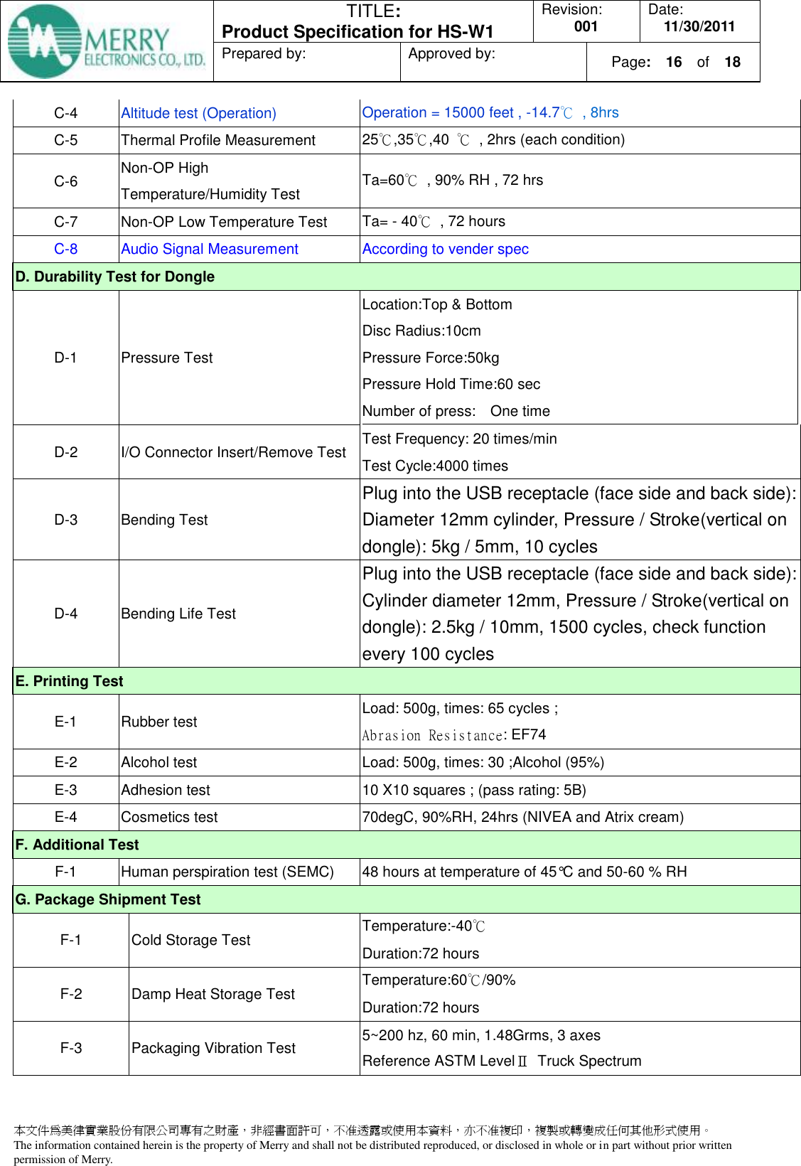
![TITLE: Product Specification for HS-W1 Revision: 001 Date: 11/30/2011 Prepared by: Approved by: Page: 17 of 18 本文件為美律實業股份有限公司專有之財產,非經書面許可,不准透露或使用本資料,亦不准複印,複製或轉變成任何其他形式使用。 The information contained herein is the property of Merry and shall not be distributed reproduced, or disclosed in whole or in part without prior written permission of Merry. F-4 Packaging Bump Test Pulse Shape:Half-Sine wave Peak Acceleration:40G Duration: 6+-2ms Direction : Normal position Times:4000 F-5 Non- Packaging Bump Test Pulse Shape:Half-Sine wave Peak Acceleration:40G Duration: 9ms Direction : Normal position Times:1000 F-6 Packaging Drop Test Package Weight (KG) Drop Height (cm) No. Drops (Times) 0 ~ 9.1 91 10 9.2 ~ 18.2 76 10 18.3 ~ 27.2 61 10 27.3~45.4 46 10 10 Drops : 1 corner,3 edges and 6 surfaces F-7 Package Compression Test [((stack layer -1)+3)*(one carton loading)]+Storage test (-40℃,48hrs+60℃/90%, 48hrs) condition. I. EMC & RF EMC pre-test ESD, CS, OTA & RE J. Performance J-1 Listen time test Max VOL(mA) 1K tone J-2 Standby time test Power on and RF function is OFF NCC 警語 經型式認證合格之低功率射頻電機,非經許可,公司、商號或使用者均不得擅自變更頻率、加大功率或變更原設計之特性及功能。 低功率射頻電機之使用不得影響飛航安全及干擾合法通信;經發現有干擾現象時,應立即停用,並改善至無干擾時方得繼續使用。 前項合法通信,指依電信法規定作業之無線電通信。低功率射頻電機須忍受合法通信或工業、科學及醫療用電波輻射性電機設備之干擾。](https://usermanual.wiki/ASUSTeK-Computer/HSW1HEADSET/User-Guide-1596758-Page-17.png)