ASUSTeK Computer PCCWL127 Wireless LAN Card User Manual
ASUSTeK Computer Inc Wireless LAN Card
UserManual.wiki
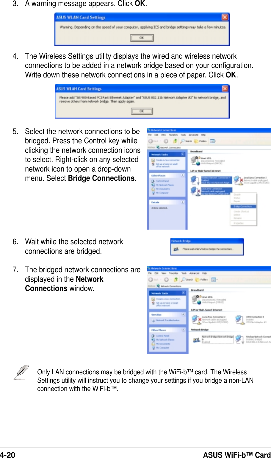
>
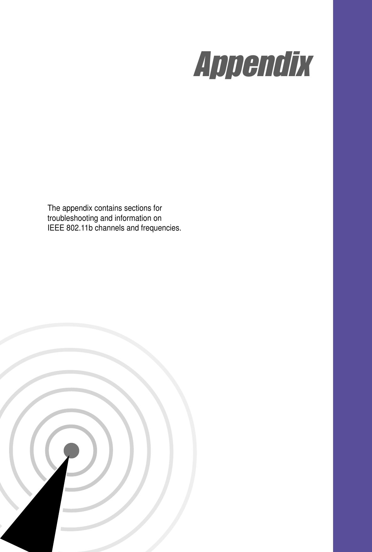
ASUSTeK Computer
>
PCCWL127 User Manual
User Manual
Navigation menu
Upload a User Manual
Namespaces
Wiki Guide
HTML
PDF
Info
Views
User Manual
Discussion / Help
Navigation
![viSafety informationIn order to maintain compliance with the FCC RF exposure guidelines, thisequipment should be installed and operated with minimum distance of more than[20cm] between the radiator and your body. Use only with supplied antenna.Unauthorized antenna, modification, or attachments could damage the transmitterand may violate FCC regulations.Any changes or modifications not expressly approved in this manualcould void your authorization to use this device.MPE StatementYour device contains a low power transmitter. When device is transmitted it sendsout Radio Frequency (RF) signal.Caution Statement of the FCC Radio Frequency Exposure>This Wireless LAN radio device has been evaluated under FCC Bulletin OET 65Cand found compliant to the requirements as set forth in CFR 47 Sections2.1091, and 15.247(b)(4) addressing RF Exposure from radio frequencydevices. The radiation output power of this Wireless LAN device is far belowthe FCC radio frequency exposure limits. Nevertheless, this device shall beused in such a manner that the potential for human contact during normaloperation is minimized. Use in a portable or body-worn configuration isstrictly prohibited. Separate approval is required for all other operatingconfigurations, including portable configurations with respect to 2.1093 anddifferent antenna configurations.When using this device, a certain separation distance between antenna andnearby persons has to be kept to ensure RF exposure compliance. In order to2003/12/24comply with the RF exposure limits established in the ANSI C95.1 standards,the distance between the antennas and the user should not be less than 20cm.GermanyTel.: +49-9194-9016Fax: +49-9194-8125Mailto:kknoerig@emcc.de](https://usermanual.wiki/ASUSTeK-Computer/PCCWL127/User-Guide-388311-Page-6.png)