ASUSTeK Computer PCCWL127 Wireless LAN Card User Manual
ASUSTeK Computer Inc Wireless LAN Card
User Manual

WiFi-b™ Card
Wireless Fidelity Card
User Guide
®

ii
Checklist
Copyright © 2003 ASUSTeK COMPUTER INC. All Rights Reserved.
No part of this manual, including the products and software described in it, may be
reproduced, transmitted, transcribed, stored in a retrieval system, or translated into any
language in any form or by any means, except documentation kept by the purchaser for
backup purposes, without the express written permission of ASUSTeK COMPUTER INC.
(“ASUS”).
Product warranty or service will not be extended if: (1) the product is repaired, modified or
altered, unless such repair, modification of alteration is authorized in writing by ASUS; or (2)
the serial number of the product is defaced or missing.
ASUS PROVIDES THIS MANUAL “AS IS” WITHOUT WARRANTY OF ANY KIND, EITHER
EXPRESS OR IMPLIED, INCLUDING BUT NOT LIMITED TO THE IMPLIED WARRANTIES
OR CONDITIONS OF MERCHANTABILITY OR FITNESS FOR A PARTICULAR PURPOSE.
IN NO EVENT SHALL ASUS, ITS DIRECTORS, OFFICERS, EMPLOYEES OR AGENTS BE
LIABLE FOR ANY INDIRECT, SPECIAL, INCIDENTAL, OR CONSEQUENTIAL DAMAGES
(INCLUDING DAMAGES FOR LOSS OF PROFITS, LOSS OF BUSINESS, LOSS OF USE
OR DATA, INTERRUPTION OF BUSINESS AND THE LIKE), EVEN IF ASUS HAS BEEN
ADVISED OF THE POSSIBILITY OF SUCH DAMAGES ARISING FROM ANY DEFECT OR
ERROR IN THIS MANUAL OR PRODUCT.
SPECIFICATIONS AND INFORMATION CONTAINED IN THIS MANUAL ARE FURNISHED
FOR INFORMATIONAL USE ONLY, AND ARE SUBJECT TO CHANGE AT ANY TIME
WITHOUT NOTICE, AND SHOULD NOT BE CONSTRUED AS A COMMITMENT BY ASUS.
ASUS ASSUMES NO RESPONSIBILITY OR LIABILITY FOR ANY ERRORS OR
INACCURACIES THAT MAY APPEAR IN THIS MANUAL, INCLUDING THE PRODUCTS
AND SOFTWARE DESCRIBED IN IT.
Products and corporate names appearing in this manual may or may not be registered
trademarks or copyrights of their respective companies, and are used only for identification or
explanation and to the owners’ benefit, without intent to infringe.
E1414
Revised Edition V2
September 2003

iii
Contents
Notices ........................................................................................................ v
Safety information ...................................................................................... vi
About this guide ......................................................................................... vi
WiFi-b™ specifications summary ............................................................. viii
Chapter 1: Product introduction
1.1 Welcome ........................................................................................ 1-2
1.2 Package contents .......................................................................... 1-2
1.3 Features ........................................................................................ 1-2
1.4 Card layout .................................................................................... 1-3
1.5 LED indicators ............................................................................... 1-3
Chapter 2: Hardware installation
2.1 System requirements ..................................................................... 2-2
2.2 Installing the WiFi-b™ card ........................................................... 2-3
2.3 Antenna placement ........................................................................ 2-3
2.4 WiFi-b™ modes ............................................................................. 2-4
2.5 Network setup ................................................................................ 2-4
Chapter 3: Software installation
3.1 Support CD information ................................................................. 3-2
3.1.1 Installing the WLAN Card Utilities and driver ................... 3-2
3.1.2 Setting the Windows® XP wireless options ..................... 3-2
3.1.3 Other support CD options ................................................ 3-2
3.2 Setup Wizard ................................................................................. 3-3
3.2.1 Selecting the WiFi-b™ operation mode ........................... 3-3
3.2.2 Station Mode.................................................................... 3-3
3.2.3 My Configuration.............................................................. 3-5
3.3 Internet Connection Sharing (ICS) .............................................. 3-10
3.3.1 Broadband connection that requires an account ........... 3-10
3.3.2 Broadband connection that is always on ....................... 3-14
3.3.3 Dial-up modem .............................................................. 3-15
Chapter 4: Utility information
4.1 The Control Center utility ............................................................... 4-2
4.1.1 Control Center icons ........................................................ 4-2

iv
Contents
4.2 Control Center Right-click menu .................................................... 4-2
4.2.1 Wireless LAN Card Settings ............................................ 4-3
4.2.2 Help Menu ....................................................................... 4-9
4.2.3 Change Mode .................................................................. 4-9
4.2.4 Preferences ................................................................... 4-10
4.2.5 About Control Center ..................................................... 4-10
4.3 Control Center Left-click menu .................................................... 4-10
4.4 Configuring WiFi-b™ by Wireless Settings utility ........................ 4-11
4.4.1 Station Mode (STA) ....................................................... 4-11
4.4.2 Soft Access Point Mode (Soft AP) ................................. 4-13
4.5 Internet Connection Sharing (ICS) .............................................. 4-16
4.5.1 Connect to the Internet using a broadband
connection that is always on .......................................... 4-16
4.5.2 Connect to the Internet using a broadband or
dial-up connection that requires an account .................. 4-17
4.6 Network Bridge ............................................................................ 4-19
Appendix
A.1 Troubleshooting ............................................................................ A-2
A.2 Channels ...................................................................................... A-5

v
Notices
Federal Communications Commission Statement
This device complies with FCC Rules Part 15. Operation is subject to the following
two conditions:
•This device may not cause harmful interference, and
•This device must accept any interference received including interference that
may cause undesired operation.
This equipment has been tested and found to comply with the limits for a Class B
digital device, pursuant to Part 15 of the FCC Rules. These limits are designed to
provide reasonable protection against harmful interference in a residential
installation. This equipment generates, uses and can radiate radio frequency energy
and, if not installed and used in accordance with manufacturer’s instructions, may
cause harmful interference to radio communications. However, there is no guarantee
that interference will not occur in a particular installation. If this equipment does
cause harmful interference to radio or television reception, which can be determined
by turning the equipment off and on, the user is encouraged to try to correct the
interference by one or more of the following measures:
•Reorient or relocate the receiving antenna.
•Increase the separation between the equipment and receiver.
•Connect the equipment to an outlet on a circuit different from that to which the
receiver is connected.
•Consult the dealer or an experienced radio/TV technician for help.
The use of shielded cables for connection of the monitor to the
graphics card is required to assure compliance with FCC regulations.
Changes or modifications to this unit not expressly approved by the
party responsible for compliance could void the user’s authority to
operate this equipment.
Canadian Department of Communications Statement
This digital apparatus does not exceed the Class B limits for radio noise emissions
from digital apparatus set out in the Radio Interference Regulations of the Canadian
Department of Communications.
This class B digital apparatus complies with Canadian ICES-003.

vi
Safety information
In order to maintain compliance with the FCC RF exposure guidelines, this
equipment should be installed and operated with minimum distance of more than
[20cm] between the radiator and your body. Use only with supplied antenna.
Unauthorized antenna, modification, or attachments could damage the transmitter
and may violate FCC regulations.
Any changes or modifications not expressly approved in this manual
could void your authorization to use this device.
MPE Statement
Your device contains a low power transmitter. When device is transmitted it sends
out Radio Frequency (RF) signal.
Caution Statement of the FCC Radio Frequency Exposure
>
This Wireless LAN radio device has been evaluated under FCC Bulletin OET 65C
and found compliant to the requirements as set forth in CFR 47 Sections
2.1091, and 15.247(b)(4) addressing RF Exposure from radio frequency
devices. The radiation output power of this Wireless LAN device is far below
the FCC radio frequency exposure limits. Nevertheless, this device shall be
used in such a manner that the potential for human contact during normal
operation is minimized. Use in a portable or body-worn configuration is
strictly prohibited. Separate approval is required for all other operating
configurations, including portable configurations with respect to 2.1093 and
different antenna configurations.
When using this device, a certain separation distance between antenna and
nearby persons has to be kept to ensure RF exposure compliance. In order to
2003/12/24
comply with the RF exposure limits established in the ANSI C95.1 standards,
the distance between the antennas and the user should not be less than 20cm.
Germany
Tel.: +49-9194-9016
Fax: +49-9194-8125
Mailto:kknoerig@emcc.de

vii
About this guide
This user guide contains the information you need to install and configure your
WiFi-b™ card.
How this guide is organized
This manual contains the following parts:
•Chapter 1: Product introduction
This chapter describes the features of the WiFi-b™ card. It presents the card
layout, the standard package contents and LED indicators.
•Chapter 2: Hardware installation
This chapter provides a step-by-step procedure on installing the WiFi-b™ card
into an ASUS motherboard. It also provides information on the system
requirements and recommended WiFi-b™ wireless network settings.
•Chapter 3: Software installation
This chapter provides information on the WiFi-b™ card software installation
and describes configuration of WiFi-b™ using the setup wizard.
•Chapter 4: Utility information
This chapter provides information on how to configure the WiFi-b™ using the
Control Center utility.
•Appendix
The appendix contains sections for troubleshooting and information on
IEEE 802.11b channels and frequencies.
Conventions used in this guide
To make sure that you perform certain tasks properly, take note of the following
symbols used throughout this manual.
WARNING: Information to prevent injury to yourself when trying to
complete a task.
CAUTION: Information to prevent damage to the components when
trying to complete a task.
IMPORTANT: Information that you MUST follow to complete a task.
NOTE: Tips and additional information to aid in completing a task.

viii
WiFi-b™ specifications summary
Standard IEEE 802.11b
Technology Direct Sequence Spread Spectrum (DSSS)
Data Transfer Rate 11Mbps (with automatic fallback to 5.5, 2 and 1Mbps)
Host Interface ASUS proprietary WiFi-b™ interface
Network Types Supports Infrastructure and Ad Hoc networks
Frequency Band 2.4 GHz ~ 2.5 GHz
Security 64-bit/128-bit configurable WEP encryption
Access Point Software access point function supports up to
31 wireless clients (Windows
®
XP only)
Operating Distance Indoors: 100 ft (30 m) @ 11Mbps
Outdoors: 1000 ft (300 m) @ 11Mbps
Supported OS Station Mode: Windows
®
98SE/ME/2000/XP
Soft AP Mode: Windows
®
XP
Antenna Stand-alone dipolar antenna
*Specifications are subject to change without notice.

Chapter 1
This chapter describes the features of the
WiFi-b™ card. It presents the card layout, the
standard package contents and LED indicators.
Product introduction

1-2
ASUS WiFi-b™ Card
1.2 Package contents
Check the following items in your ASUS WiFi-b™ package. Contact your retailer if
any item is damaged or missing.
ASUS WiFi-b™ card
ASUS WiFi-b™ antenna
User Guide
WiFi-b™ support CD*
* If you purchased an ASUS Wireless Edition motherboard, the WiFi-b™
support CD contents are included in the motherboard support CD.
1.3 Features
The WiFi-b™ card gives you freedom to connect to a wired or wireless local area
network and the Internet without the wires and cables. Employing the Direct
Sequence Spread Spectrum (DSSS) technology, the WiFi-b™ card is capable of
transmitting and receiving signals through radio waves on the 2.4 GHz band.
Here are other WiFi-b™ features:
•Reliable data transfer rates of up to 11Mbps with automatic fallback to 5.5, 2,
and 1Mbps
•Secure data transmission via Wired Equivalent Privacy (WEP) encryption
•Operating distance of up to 100 ft (30 m) indoors and 1000 ft (300m) outdoors*
•Easy installation and full software support
•Soft access point function supports up to 31 wireless clients (Windows
®
XP only)
•Supports infrastructure (WiFi-b™ to access point) and ad-hoc (WiFi-b™ to other
wireless clients) network types
•Windows
®
98SE/ME/2000/XP compatible
* The WiFi-b™ operating distance may be shorter if there are walls, barriers, or
interferences in the home layout or operating environment.
1.1 Welcome
Thank you for choosing the ASUS WiFi-b™ Card! The WiFi-b™ card is a wireless
network interface card for ASUS motherboards with the proprietary Wi-Fi slot. This
card conforms to the IEEE 802.11b standard for wireless local area network
(WLAN) assuring you of seamless connection to any wireless network. The
WiFi-b™ card also allows you to share a single Internet connection with other
computers making it a perfect solution for your home or small office network. With
easy installation and full software support, WiFi-b™ is sure to keep you ahead in
the world of wireless computing.
Chapter 1: Product Introduction
1-3
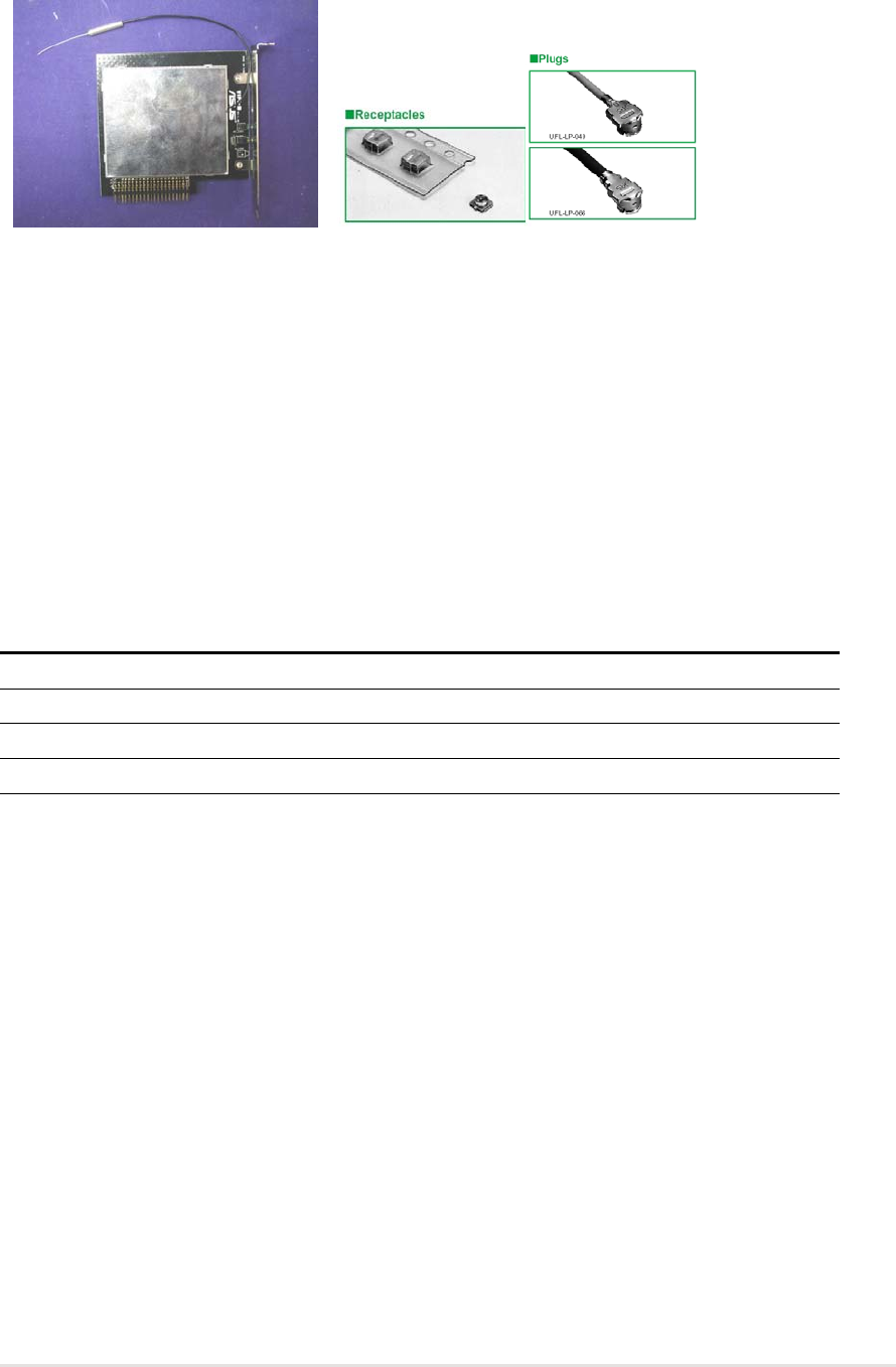
1.4 Card layout
1.5 LED indicators
The WiFi-b™ card comes with a Data Transmission (Green AIR) and Network Link
(Yellow LINK) LED indicators. Refer to the table below for LED indications.
AIR LINK Meaning
Fast Blink ON WiFi-b™ radio is on and is transmitting/receiving data
ON ON WiFi-b™ radio is on but no data activity
OFF OFF No power / WiFi-b™ radio is off or disabled
Blink OFF WiFi-b™ is not connected to a wireless LAN
WiFi-b™ connectors

1-4
ASUS WiFi-b™ Card

Chapter 2
This chapter provides a step-by-step procedure
on installing the WiFi-b™ card into an ASUS
motherboard that supports Wi-Fi specification. It
also provides information on system
requirements and recommended wireless
network settings.
Hardware installation
ASUS WiFi-b™ Card
2-2
Follow these instructions to install the WiFi-b™ card in your system.
1. Make sure that the PC is turned off. Unplug the power cord from the electrical
socket.
2. Remove the PC cover.
3. Locate the Wi-Fi slot. Refer to your motherboard documentation for the Wi-Fi
slot location.
4. Remove the rear panel bracket opposite the Wi-Fi slot. Keep the screw
for later use.
2.2 Installing the WiFi-b
™
card
Before handling the card, touch a bare metal portion of your PC to discharge static
electricity from your body. Wear a wrist strap grounded to the PC chassis when
handling the card.
The PCI5 and the Wi-Fi slot may not be used simultaneously on certain
motherboards. Check your motherboard documentation for this limitation.
2.1 System requirements
Before installing the WiFi-b™ card, make sure that your system meets the
following requirements.
•ASUS motherboard with Wi-Fi slot
•Intel
®
Pentium™ 4 or AMD K7/K8 system
•Minimum 64MB system memory
•Windows
®
98SE/2000/ME/XP operating system
•CD-ROM drive for software and drivers installation
The following ASUS motherboards support the WiFi-b™ card: P4C800-E Deluxe,
P4C800 Deluxe, P4C800, P4P800 Deluxe, P4P800, P4P800S-E Deluxe, P4P800S,
P4P8X, P4S800D Deluxe, P4S800D, P4S800, K8V Deluxe, A7N8X-E Deluxe, and
A7V600. Visit the ASUS website for an updated list of motherboards with Wi-Fi slot.
Notes for P4P800 Deluxe/P4C800 Deluxe/P4P800/P4C800/P4C800-E Deluxe
motherboards:
•Update the BIOS before installing the WiFi-b™ card. Download the latest BIOS
file from the ASUS website.
•Update the 3Com utilities to V.046 before installing the WiFi-b™ card. The 3Com
utility update is available in the WiFi-b™ support CD.
•The PCI slot nearest the WiFi slot may not be used simultaneously with the Wi-Fi
slot. If a PCI card is installed on this slot, transfer it to another PCI slot before
installing WiFi-b™.
Chapter 2: Hardware Installation
2-3
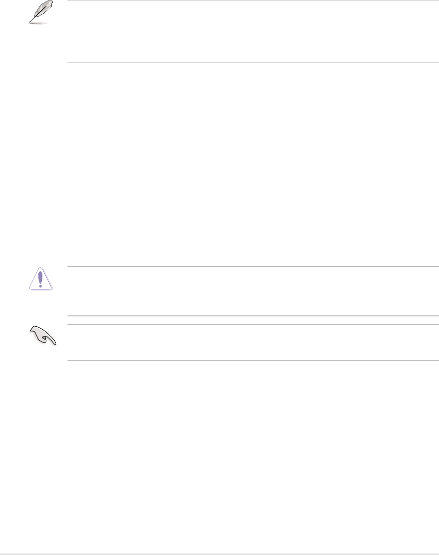
5. Carefully insert the card into the Wi-Fi slot.
To prevent incorrect orientation, a WiFi-b™ connector pin is removed to match the
covered hole on the Wi-Fi slot.
6. Secure the card with the screw that you removed earlier.
7. Replace the PC cover and plug in the power cord.
9. Connect the dipolar antenna twist-on connector to the antenna connector
(male) of the WiFi-b™ card.
8. Turn on the computer.
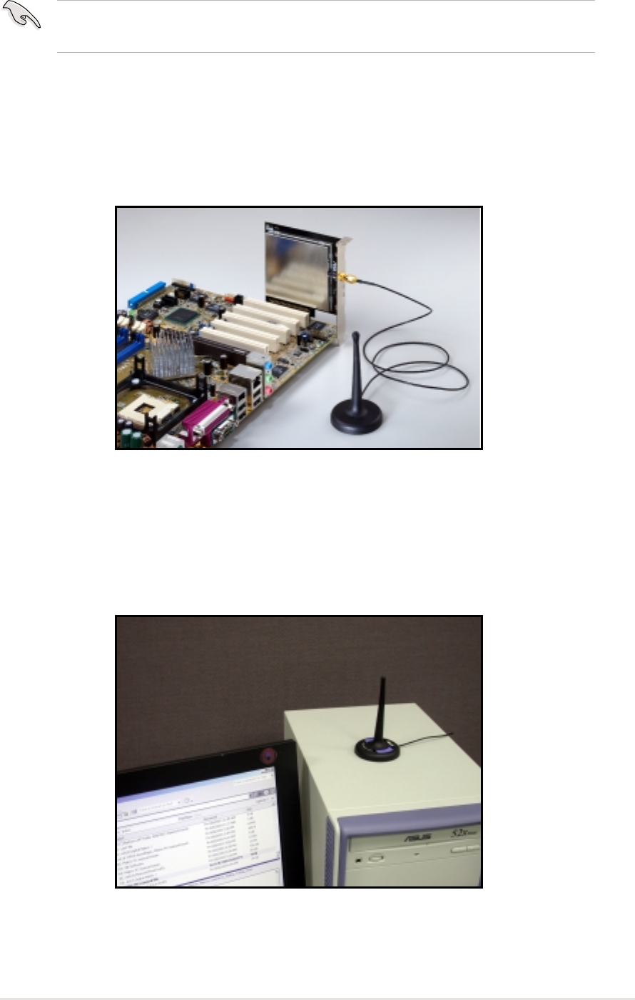
2.3 Antenna placement
Place the antenna at an elevated location to receive or transmit better signal. Do
not place the antenna under your table or in a closed compartment.
An installed WiFi-b™ card
ASUS WiFi-b™ Card
2-4
2.4 WiFi-b
™
modes
The WiFi-b™ card may be set to Station (STA) or Soft Access Point (Soft AP)
mode. In STA mode, WiFi-b™ connects to a wireless or wired network through an
access point. In Soft AP mode, WiFi-b™ connects other computers with wireless
devices to a wireless or wired network.
The following section describes the WiFi-b™ card functions in a typical home or
small office network.
2.5 Network setup
After installing the WiFi-b™ card, determine your network settings to avail all
WiFi-b™ features. The following network settings are recommended.
WiFi-b™ in Soft Access Point (Soft AP) Mode - Internet Connection Sharing (ICS)
The Internet Connection Sharing (ICS) feature allows wireless clients to share a
single Internet connection. In this setup, WiFi-b™ automatically assigns a virtual IP
address to each of the wireless clients. The computer with the WiFi-b™ card must
create a broadband network connection.
ADSL Modem
Wireless clients
INTERNET
PC with WiFi-b™
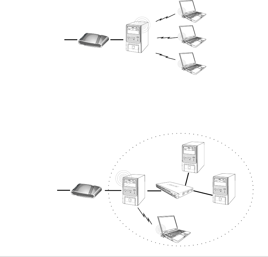
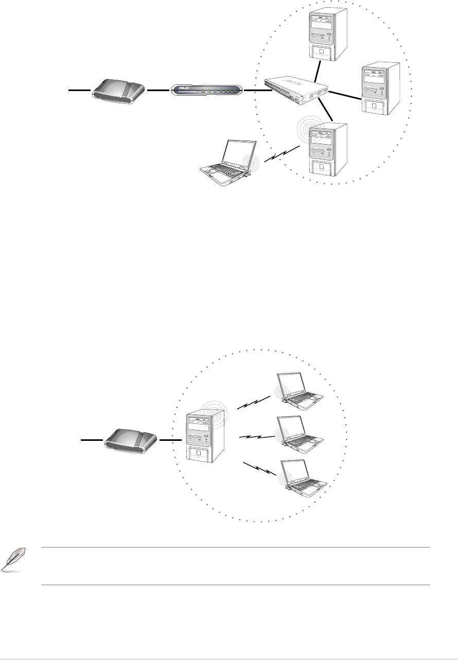
WiFi-b™ in Soft Access Point (Soft AP) Mode -ICS and Bridge
In this setup, WiFi-b™ bridges the computer’s network connection to the ADSL
modem (wired) and to the wireless client (wireless). WiFi-b™ assigns a virtual IP
address to the wireless client. The PC with the installed WiFi-b™ card must setup
a broadband network connection.
ADSL Modem Hub
PC1
PC2
Wireless client
INTERNET
PC with
WiFi-b™
Chapter 2: Hardware Installation
2-5
ADSL Modem Router Hub
PC1
PC2
PC3 with
WiFi-b™
Wireless client
INTERNET
WiFi-b™ in Soft Access Point (Soft AP) Mode - Bridge
In this setup, WiFi-b™ functions as a wireless hub allowing a wireless client to
access the ADSL modem and the Internet. The router assigns a virtual Internet
Protocol (IP) address to the wireless client.
WiFi-b™ in Soft Access Point (Soft AP) Mode - Bridge
In this setup, WiFi-b™ bridges the computer’s network connection to the ADSL
modem and to the wireless clients allowing the latter access to the Internet. The
real IP address for each wireless client is supplied by the Internet Service Provider.
In this setup, every computer must create a broadband network connection.
ADSL Modem
Wireless
clients
INTERNET
PC with
WiFi-b™
The number of computers that can connect simultaneously to the Internet depends
on the number of IP address assigned by the ISP.
ASUS WiFi-b™ Card
2-6
ADSL Modem Router Hub
PC1 PC2
Wireless clients
INTERNET
Access Point
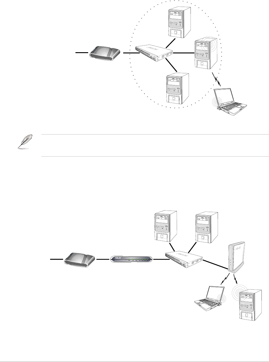
WiFi-b™ in Station Mode - Infrastructure Network
When set to Station Mode, WiFi-b™ connects to a wired or wireless network via an
access point. The router assigns a virtual IP address to each wireless client.
WiFi-b™ in Soft Access Point (Soft AP) Mode - Bridge
This setup applies to a host computer with an installed WiFi-b™ card and a
network adapter connected to a hub. By bridging the network connections to the
hub and the wireless client, the latter is allowed connection to the Internet via the
ADSL modem. The Internet Service Provider (ISP) assigns the real IP address to
the wireless client. In this setup, every computer must create a broadband network
connection.
ADSL Modem Hub
PC2
PC3
Wireless client
INTERNET
PC1 with
WiFi-b™
The number of computers that can connect simultaneously to the Internet depends
on the number of IP address assigned by the ISP.

Chapter 3
This chapter provides information on the
WiFi-b™ card software installation and
describes configuration of WiFi-b™ using the
setup wizard.
Software installation
3-2
ASUS WiFi-b™ Card
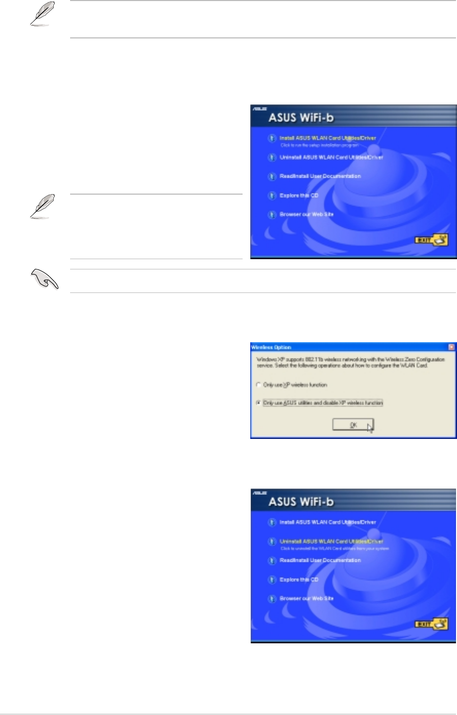
3.1.2 Setting the Windows
®
XP wireless options
The Wireless Option window appears
after the software installation if you are
using Windows XP
®
. Select “Only use
ASUS utilities and disable XP wireless
function” to avail all WiFi-b™ card
features. Click OK.
3.1 Support CD information
The Support CD contents are subject to change at anytime without notice. Visit the
ASUS website for updates.
3.1.1 Installing the WLAN Card Utilities and driver
To install the WiFi-b™ card driver and the Control Center Utility in your computer:
1. Insert the support CD into the
CD-ROM drive.
2. Click “Install ASUS WLAN Card
Utilities/Driver” when the ASUS
WiFi-b installation window appears.
3.1.3 Other support CD options
Uninstall ASUS WLAN Card Utilities/
Driver. Click this option to uninstall the
WLAN Card utilities and driver from your
system.
Read/Install User Documentation. Click
to view the installation and quick setup
guides in PDF format.
Explore this CD. Click this option to
explore the support CD contents.
Browse our Web Site. Click this option
to visit the ASUS website.
Click EXIT to close the installation window.
If Autorun is NOT enabled in your
computer, browse the contents of the
support CD and double click the
Setup.exe file to run the CD.
Windows
®
98SE/ME users must restart the computer after installation.
Chapter 3: Software installation
3-3
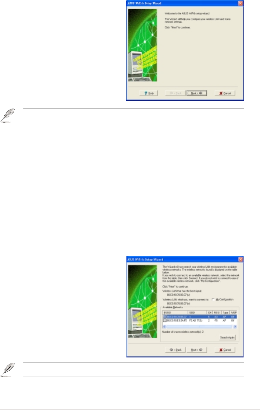
3.2 Setup Wizard
After configuring the wireless option, the
Setup Wizard window appears. Click
Next.
3.2.1 Selecting the WiFi-b™ operation mode
The default setting of the WiFi-b™ card is Station Mode in an Infrastructure type
network. The first time you run the setup wizard, it scans available wireless
networks in your location and automatically selects the network with the best
signal. The wizard also allows you to connect to any of the available networks.
If you want to set your WiFi-b™ in soft access point mode or in Ad Hoc network
setting, check My Configuration, then click Next. See section 3.2.3 “My
Configuration” for details.
3.2.2 Station Mode
Follow these instructions to set your WiFi-b™ in station (STA) mode.
Select a wireless network from the table,
then click Next. WiFi-b™ connects to the
selected network.
Click the Search Again button ro rescan available access points in your location.
The appearance of setup wizard windows varies on different operating systems.
3-4
ASUS WiFi-b™ Card
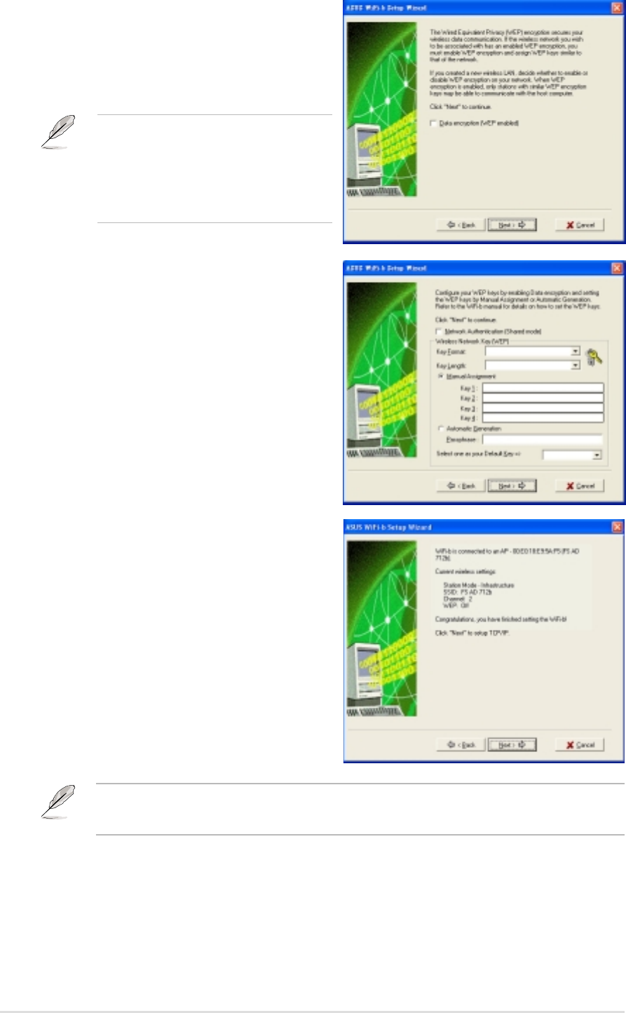
When connected, the wizard displays
information on the wireless network
WiFi-b™ is associated with. Click Next to
configure the TCP/IP settings.
If the wireless network you wish to
access has an enabled Wired
Equivalent Privacy (WEP) encryption,
the setup wizard will prompt you to
enable data encyption. Click next.
Inquire the WEP keys with the
network administrator. The WiFi-b™
and the selected wireless network
WEP keys must be identical to
establish connection.
Enter the WEP encryption keys you
obtained from the network administrator
Refer to “Config-Encryption Tab” on
page 4-6 for WEP encryption settings.
Click Next.
The wizard prompts you to return to the previous window and select another
wireless network if WiFi-b™ is not connected to the selected network.
Chapter 3: Software installation
3-5
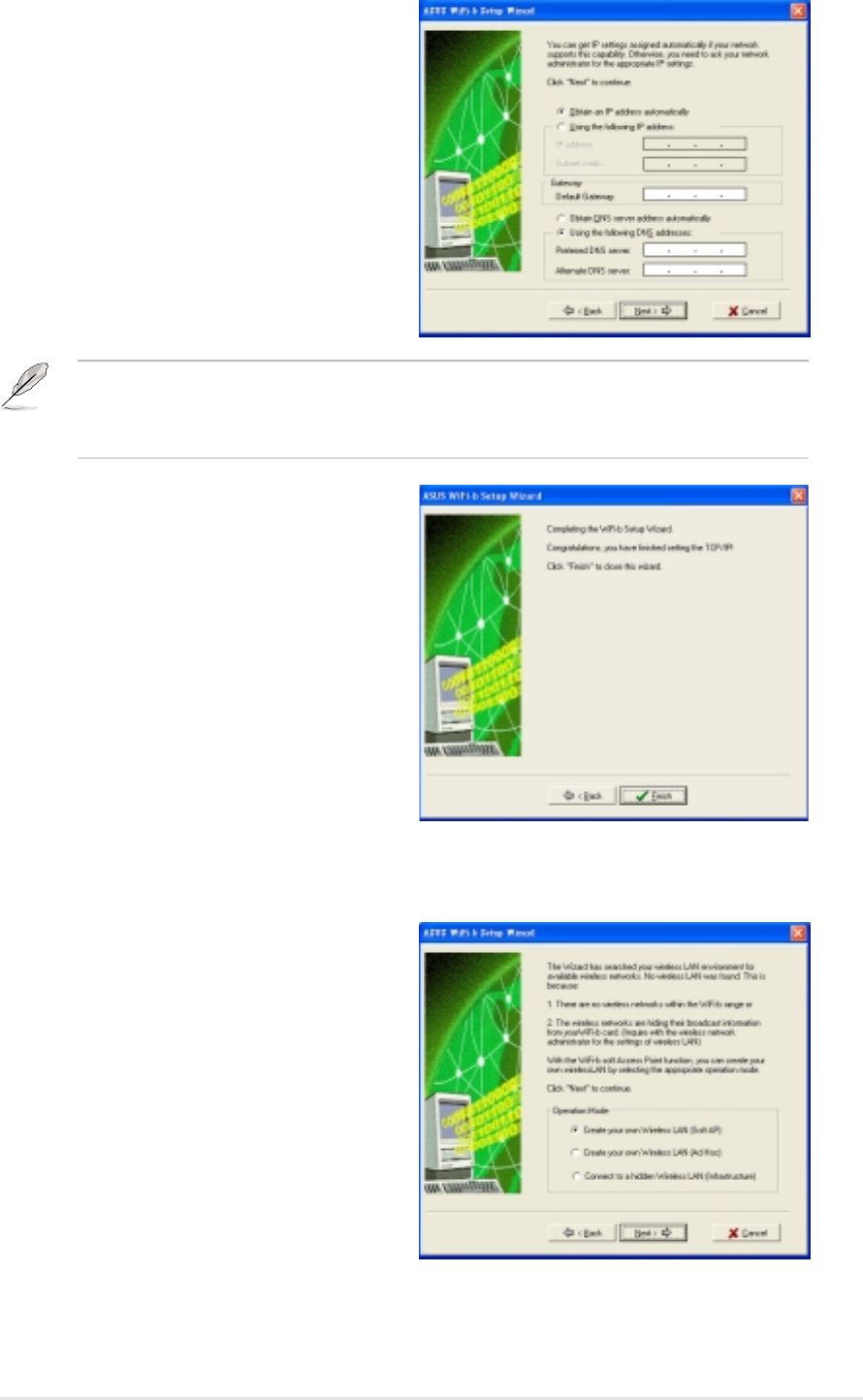
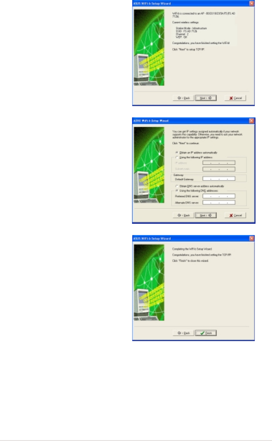
Select automatic IP settings if your
network supports automatic IP address
assignment. If not, inquire the IP settings
with your network administrator, then
enter the IP address manually. After
configuration, click Next.
The WiFi-b™ setup is complete. Click
Finish to close the setup wizard.
3.2.3 My Configuration
The setup wizard displays allows you to
set the WiFi-b™ card in three different
operation modes when you select My
Configuration. Select an operation
mode, then click Next.
The TCP/IP configuration window appears when you run the setup wizard on
Windows
®
98SE/ME/2000. The window also appears in Windows
®
XP OS if WiFi-b™
is not bridged to other network connections and has a disabled ICS function.
3-6
ASUS WiFi-b™ Card
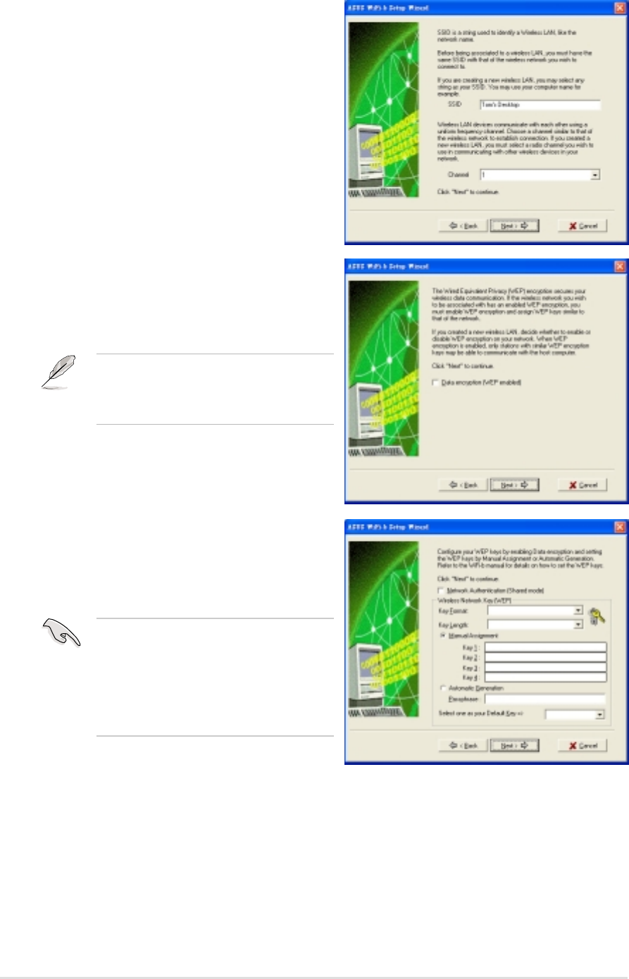
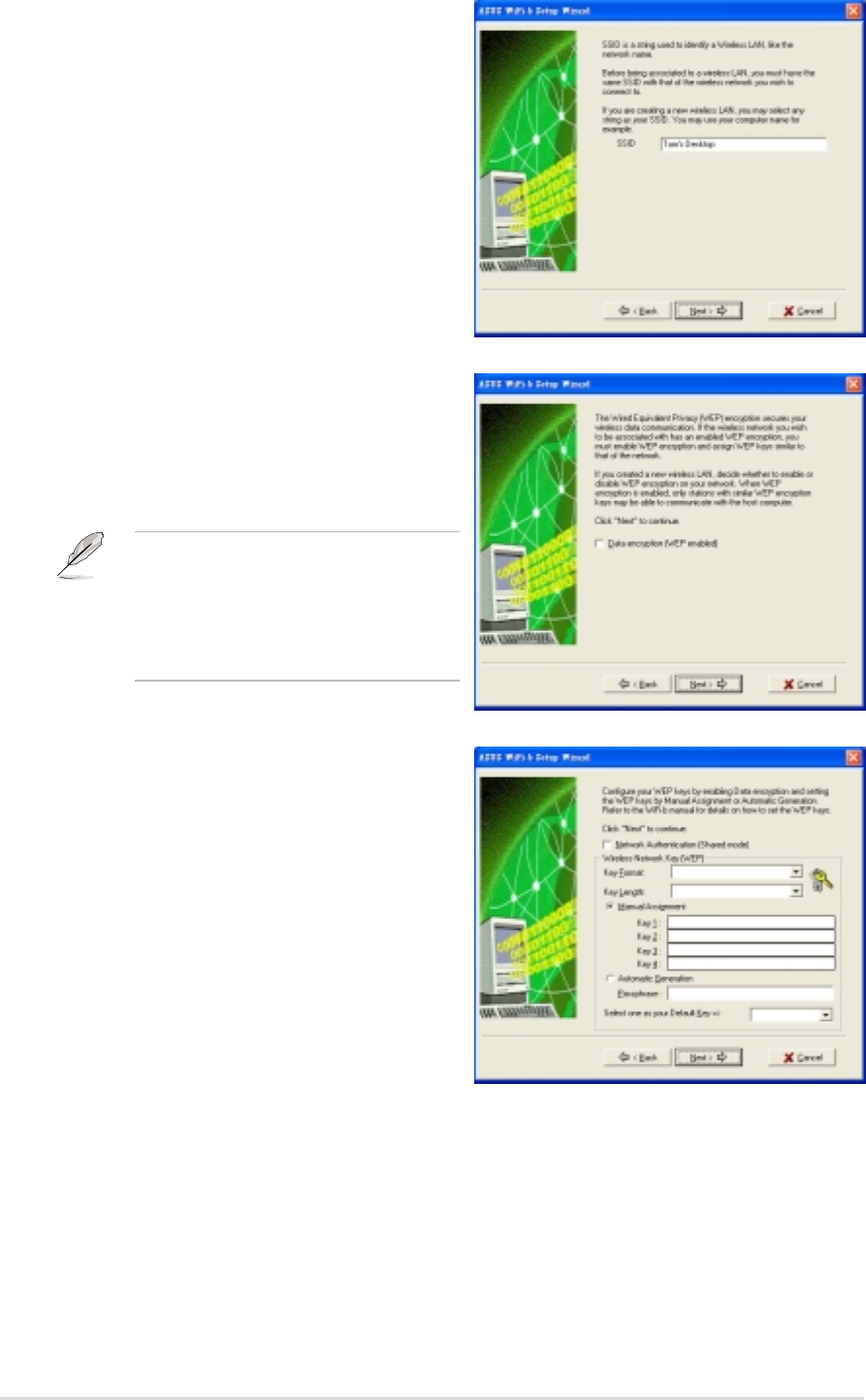
Check Data encryption (WEP enabled)
to secure your wireless network with a
Wired Equivalent Privacy (WEP)
encryption. Click Next.
Enabling data encryption prevents
unauthorized access by other
wireless networks in your location.
Create your own wireless LAN (Soft AP and Ad Hoc modes)
When prompted, assign a SSID (Network
Name) to the wireless LAN you wish to
create, then select a radio channel you
wish to use in communicating with other
wireless devices. Click Next to continue.
Assign the WEP encryption keys of your
wireless network. Refer to
“Config-Encryption Tab” on page 4-6
for WEP encryption settings. Click Next.
Keep a record of the WEP keys.
Wireless computers in your
network must have the same
WEP keys to establish
connection with the WiFi-b™.
Chapter 3: Software installation
3-7
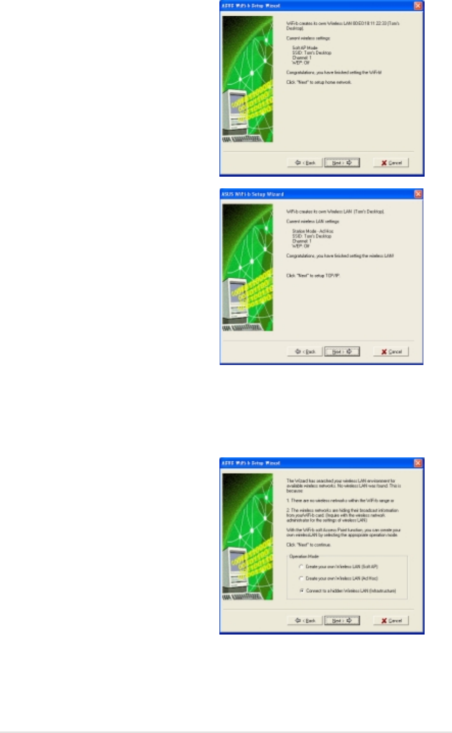
The wizard displays the settings of the
created wireless network including the
WiFi-b™ mode, SSID, channel and WEP
information.
If you created a Soft AP, click Next to
setup Internet Connection Sharing (ICS).
See section 3.3 “Internet Connection
Sharing” on page 3-10.
When WiFi-b™ is set to Ad Hoc mode,
click Next to configure the TCP/IP
settings. Refer to section 3.2.2
“Station Mode” on TCP/IP configuration.
Connecting to a hidden wireless LAN
Some access points disable their SSID broadcasting to prevent a wireless device
from finding and accessing their networks. Inquire the SSID of the hidden wireless
LAN with the network administrator. To connect to a hidden wireless LAN:
Select Connect to a hidden wireless
LAN, then click Next.
3-8
ASUS WiFi-b™ Card
When prompted, enter the SSID of the
hidden wireless LAN you obtained from
the network administrator. Click Next.
If the hidden wireless LAN you wish to
access has an enabled Wired Equivalent
Privacy (WEP) encryption, the setup
wizard will prompt you to enable data
encyption. Click next.
Inquire the WEP keys with the
network administrator. The WiFi-b™
and the hidden wireless LAN WEP
keys must be identical to establish
connection.
Enter the WEP encryption keys you
obtained from the network administrator
Refer to “Config-Encryption Tab” on
page 4-6 for WEP encryption settings.
Click Next.
Chapter 3: Software installation
3-9
The wizard displays information on the
wireless network WiFi-b™ is associated
with. Click Next to set the TCP/IP
configuration.
Select automatic IP settings if your
network supports automatic IP address
assignment. If not, inquire the IP settings
with your network administrator, then
enter the IP address manually. After
configuration, click Next.
The WiFi-b™ setup is complete. Click
Finish to close the setup wizard.
3-10
ASUS WiFi-b™ Card
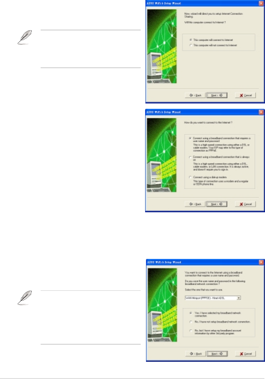
2. Select the Internet connection mode
of your computer from a list.
Click Next.
3.3.1 Broadband connection that requires an account
Follow these instructions to enable ICS if you have an existing broadband network
connection that requires a username and password.
3.3 Internet Connection Sharing (ICS)
After setting the WiFi-b™ in soft AP mode, the wizard will prompt you to setup
Internet Connection Sharing (ICS). ICS is a networking feature that allows several
computers in a wired or wireless network to share a single Internet connection. To
setup ICS:
1. Select the broadband network
connection from the drop-down list.
Click Next.
1. Select whether your computer
connects to the Internet or not.
Click Next.
The wizard will require you to create
a home network connection if your
computer is not connected to the
Internet.
If you do not have a broadband
network connection, the wizard will
instruct you to create one using the
Windows
®
interface or the support
CD from your Internet Service
Provider (ISP).
Chapter 3: Software installation
3-11
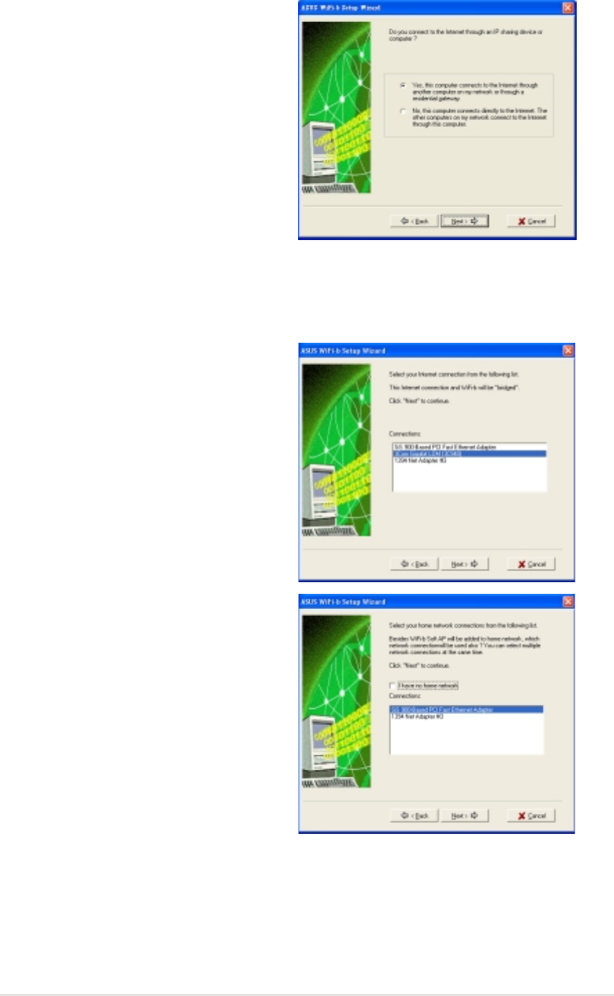
2. When prompted, select whether your
computer connects to the Internet
directly or through another computer
or residential gateway. Click Next.
1. Select the network adapter you are
using to connect to the host
computer or residential gateway.
Click Next.
2. Select the network adapters that
connect to other computers in your
home network, if any. The wizard will
bridge these networks with the
WiFi-b. Click Next.
Internet connection via another computer or residential gateway
If your computer connects to the Internet through another computer or residential
gateway:
3-12
ASUS WiFi-b™ Card
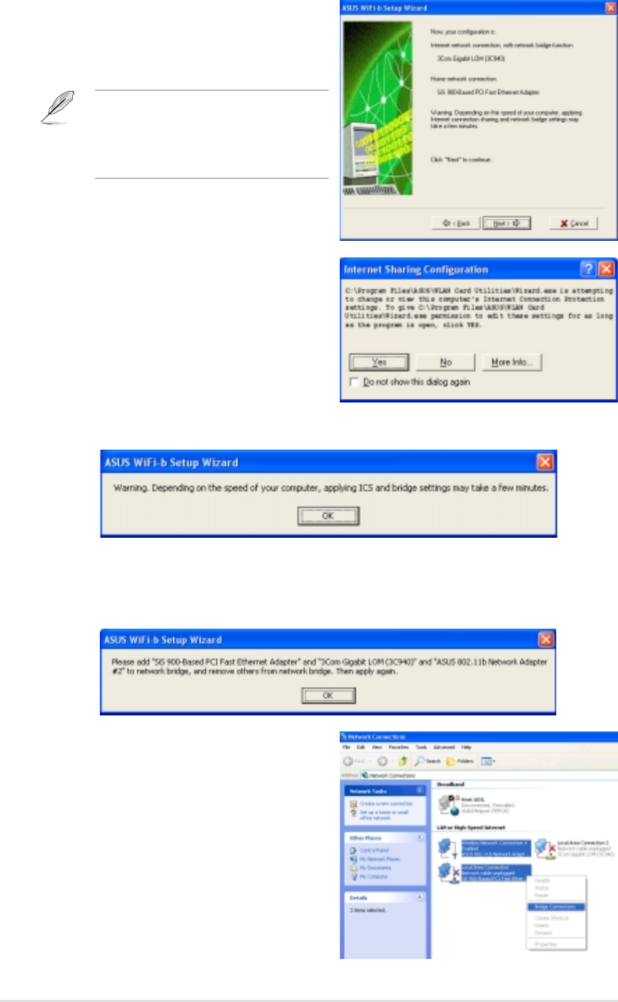
3. The wizard creates a network bridge
between your wired (LAN) and
wireless (WiFi-b™) network
connections. Click Next.
Network bridge is a process of
connecting several wired or wireless
LAN segments. See page 4-19 for
details.
4. An Internet Sharing Configuration
dialog box appears. Click Yes.
7. Select the network connections to be
bridged when the Network
Connections window appears. Press
the Control key while clicking the
network connection icons to select.
Right-click on any selected network
icon to open a drop-down menu.
Select Bridge Connections.
5. A warning dialog box appears. Click OK.
6. The wizard displays the wired and wireless network connections to be added
in a network bridge based on your configuration. Write down these network
connections in a piece of paper. Click OK.
Chapter 3: Software installation
3-13
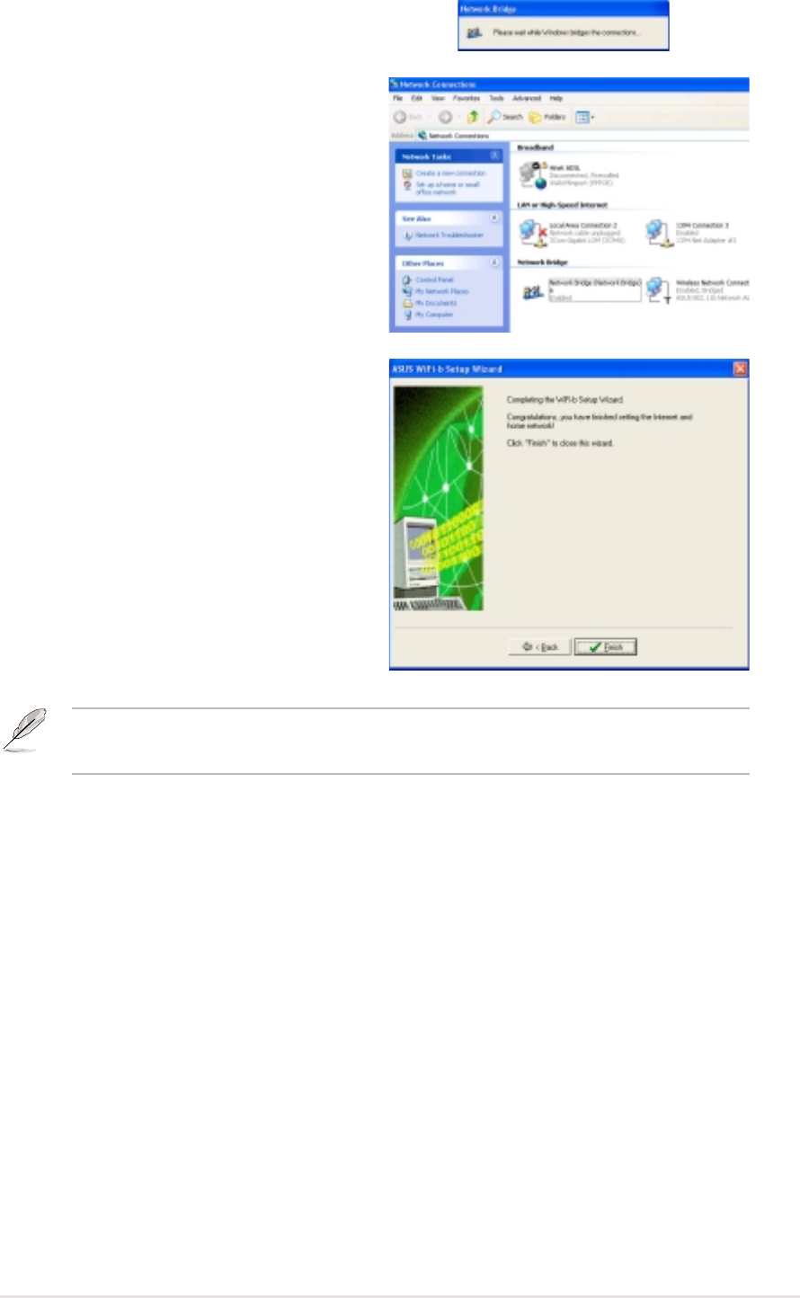
9. The bridged network connections are
displayed in the Network
Connections window.
8. The selected network connections
are bridged.
10. Click Finish to close the setup
wizard.
Refer to Windows
®
XP Help and Support Center for articles and help files on the
Network Bridge function.
3-14
ASUS WiFi-b™ Card
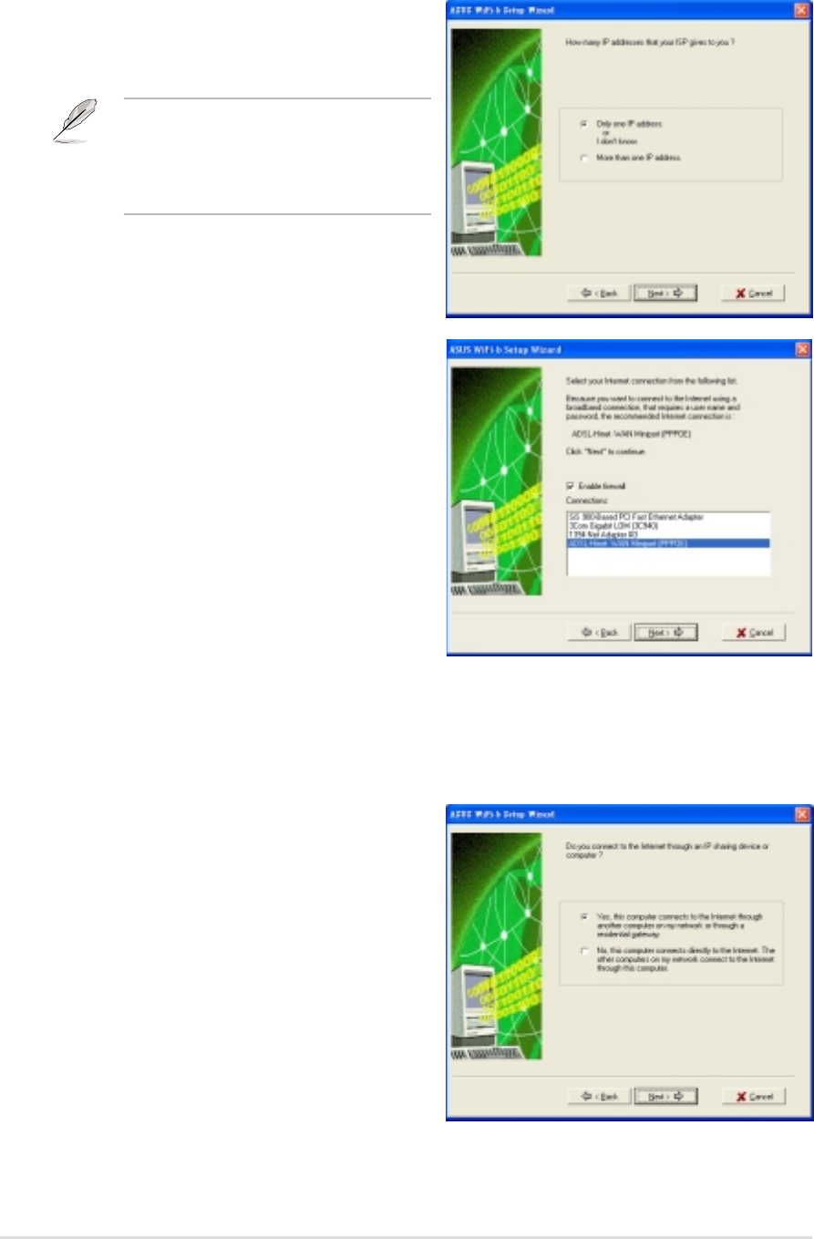
2. The setup wizard automatically
selects your broadband network
connection. Check Enable Firewall
to secure your network from
unauthorized access. Click Next.
3. Refer to instructions 2 to 10 of the
previous section to enable ICS.
3.3.2 Broadband connection that is always on
To enable ICS if you have an existing broadband network that is always on (DSL,
cable modem, or LAN):
1. Select whether your computer directly
connects to the Internet or through
another computer or residential
gateway. Click Next.
Direct internet connection
To enable ICS if your computer directly connects to the Internet:
1. Select the number of IP address
assigned by your Internet Service
Provider (ISP). Click Next.
The wizard will instruct you to enable
ICS or create a network bridge if you
are assigned two or more IP
addresses.
Chapter 3: Software installation
3-15
2. If your computer connects to the internet via another computer or residential
gateway, follow steps 2 to 10 of the “Internet connection via another
computer or residential gateway” section on pages 3-10 to 3-13.
Follow the steps in the “Direct Internet connection” section on page 3-14 if
your computer connects directly to the Internet.
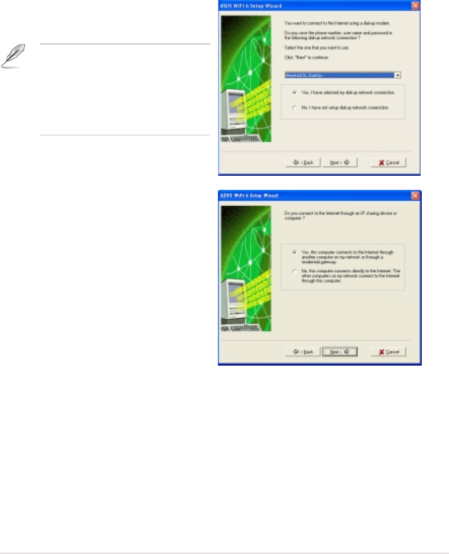
3.3.3 Dial-up modem
Follow these instructions to enable ICS if you are using a modem and a regular or
ISDN phone line.
1. Select the dial-up connection from
the drop-down list. Click Next.
If you do not have a dial-up
connection, the wizard will instruct
you to create one using the
Windows
®
interface or the support
CD from your Internet Service
Provider (ISP).
2. Select whether your computer directly
connects to the Internet or through
another computer or residential
gateway. Click Next.
3. If your computer connects to the internet via another computer or residential
gateway, follow steps 2 to 10 of the “Internet connection via another
computer or residential gateway” section on pages 3-10 to 3-13.
Follow the steps in the “Direct Internet connection” section on page 3-14 if
your computer connects directly to the Internet.

3-16
ASUS WiFi-b™ Card

Chapter 4
This chapter provides information on how to
configure the WiFi-b™ using the Control Center
utility.
Utility information
4-2
ASUS WiFi-b™ Card
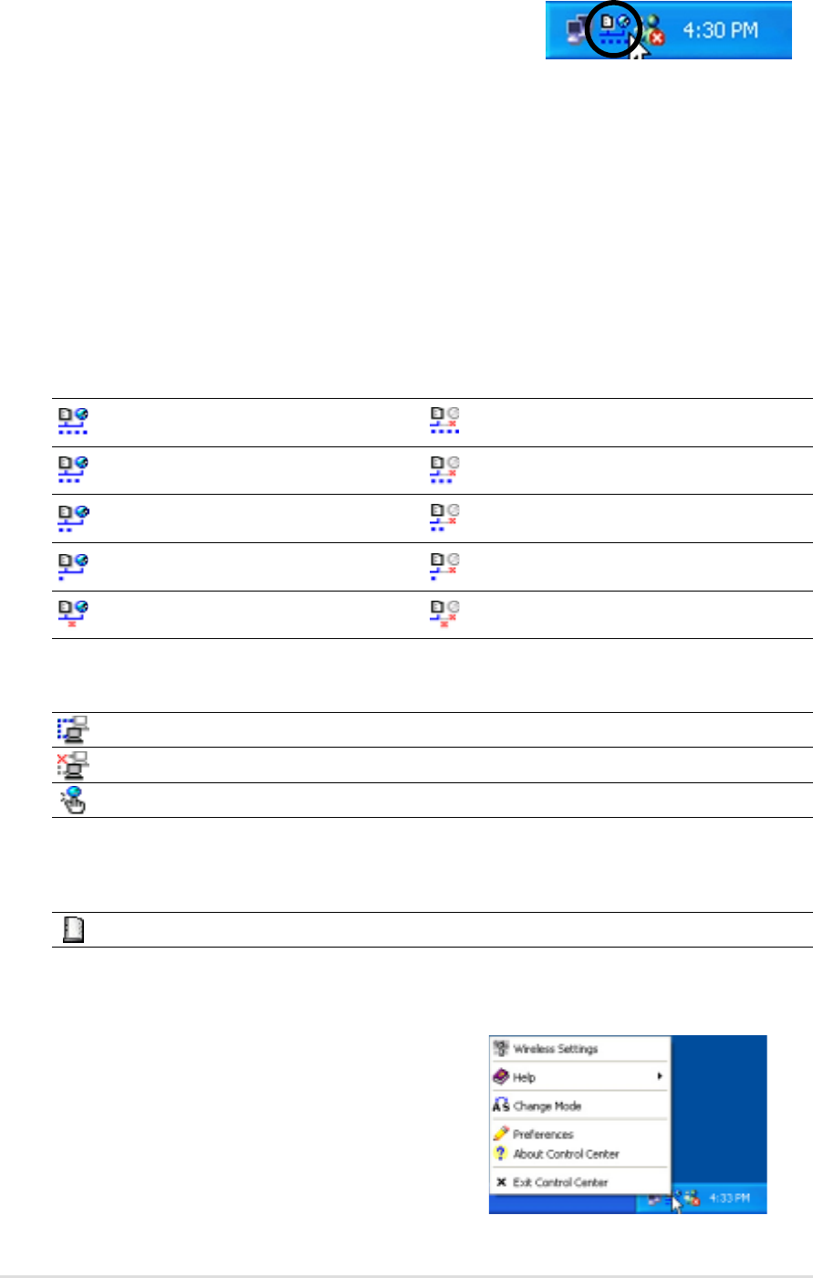
4.2 Control Center Right-click menu
Right-clicking the Control Center icon
displays the right-click menu. The following
sections describe the right-click menu
items.
4.1 The Control Center utility
The Control Center utility is a management software
that launches applications and configures network
settings. The Control Center Utility starts
automatically when the system boots and displays the Control Center icon in the
Windows
®
taskbar. The Control Center icon serves as an application launcher, and
indicator of signal quality and Internet connection.
4.1.1 Control Center icons
The Control Center icon indicates the quality of link to the access point and
connection to the Internet. Refer to the table below for icon indications.
Station Mode
Infrastructure Network Mode (WiFi-b™ to an access point)
Excellent link quality and Excellent link quality but not
connected to the Internet connected to the Internet
Good link quality and Good link quality but not
connected to the Internet connected to the Internet
Fair link quality and Fair link quality but not
connected to the Internet connected to the Internet
Poor link quality but Poor link quality and not
connected to the Internet connected to the Internet
Not linked but connected Not linked and not
to the Internet connected to the Internet
Ad-Hoc Network Mode (WiFi-b™ to other Wi-Fi device)
Linked
Not Linked
Connected to the Internet
Soft Access Point Mode
WiFi-b™ is in soft access point (Soft AP) mode.
Chapter 4: Utility information
4-3
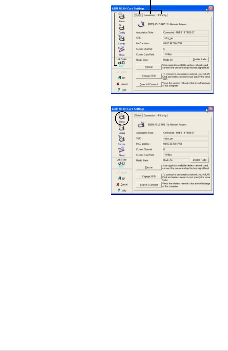
4.2.1 Wireless LAN Card Settings
The Wireless LAN Card Settings is
the main interface that allows users to
control the ASUS WiFi-b™. Use the
Wireless Settings to view the
operational and connection status, or
to modify the WiFi-b™ configuration.
The Wireless Settings window is
composed of the property window
and tabbed property sheets. Click the
icons in the property window to
display their tabbed property sheets.
Property window
Tabbed property sheets
Status - Status Tab
The Status Tab provides general
information on the WiFi-b™ card.
Association State. This field displays
the connection status and MAC address
of the network where the system is
connected.
Service Set Identifier (SSID). This field
displays the SSID of the network which
the card is associated with or is intending
to join. The SSID is a group name shared
by every member of a wireless network. Only client PCs with the same SSID are
allowed to establish a connection.
The MAC Address field displays the hardware address of a device connected to a
network.
The Current Channel field displays the radio channel that the card is currently
tuned. The channel changes as WiFi-b™ scans the available channels. See the
Appendix for channel information.
The Current Data Rate field displays the data transfer rate between the WiFi-b™
card and the access point.
The Radio State field displays the radio communication status. Click the Disable
Radio button if you wish to disable radio communication with an access point or a
Wi-Fi device.
Rescan button - Click to allow WiFi-b™ to scan available wireless networks and to
connect to the network with the best signal quality.
4-4
ASUS WiFi-b™ Card
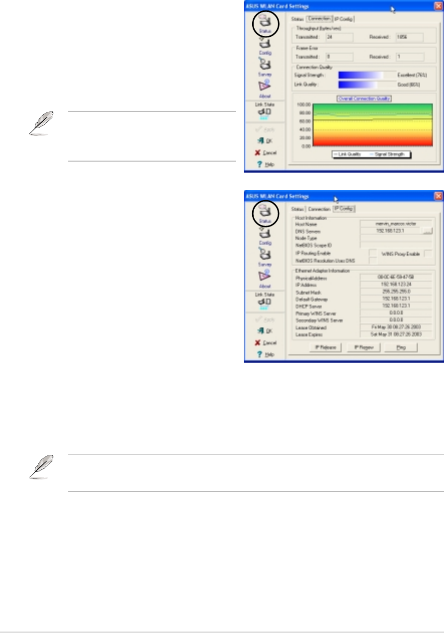
Status - IP Config Tab
The IP Config tab displays the current
host and Ethernet adapter configurations.
IP Config displays TCP/IP information
including the IP address, subnet mask,
default gateway, DNS and Windows
Internet Naming Service (WINS)
configurations.
Use the IP Config Tab to verify your
network settings.
IP Release. Click to release the DHCP IP address for the WiFi-b™ card.
IP Renew. Click to renew the DHCP IP address for the WiFi-b™ card.
Ping. Click to display the Ping tab. Use ping to verify a connection to a particular
host name or IP address.
The IP Release and IP Renew buttons may only be used on a WiFi-b card that is
configured with DHCP.
Change SSID button - Click to change the SSID. Clicking this button opens the
Config-Basic window. See “Config-Basic Tab” on next page.
Search and Connect button - Click to view all wireless networks within the range
of your system. Clicking this button opens the Site Survey window. See page 4-8.
Status - Connection Tab
The Connection Tab provides real-time
information on connection throughput,
frame errors, signal strength, link quality
and overall connection quality in graph
representation.
On soft AP mode, only the
Throughput and Frame Error fields
are displayed.
Chapter 4: Utility information
4-5
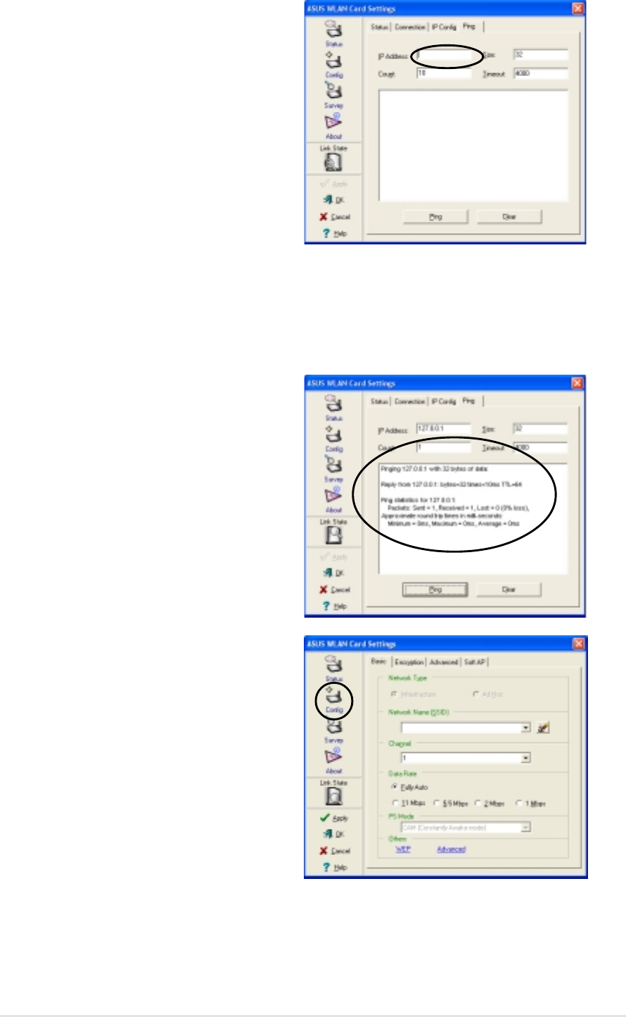
Status - Ping Tab
The Ping tab allows you to verify the
connection of the host computer with
another computer in the network. To ping
a connection:
1. Type the IP address of the connection
you want to verify in the IP Address
field.
2. Configure the ping session by
assigning the size and count of packet
to send, and the time limit for a ping
session to continue (in milliseconds).
3. Click the Ping button.
During the ping session, the Ping button toggles into a Stop button. Click Stop
anytime to cancel the ping session.
The session field displays information on
the verified connection including the
roundtrip time (minimum, maximum, and
average) and packets sent, received, and
lost after a ping session.
Click the Clear button to clear the
session field.
Config - Basic Tab
The Basic tab provides general
information on network types and other
configurations.
Network Type. Select which type of
network you wish to use. Select
Infrastructure mode to establish a
connection with an access point (AP). In
this mode, your system can access
wireless LAN and wired LAN (Ethernet)
via the AP. Select the Ad Hoc mode to
communicate directly with other mobile
clients within the WiFi-b™ range.
4-6
ASUS WiFi-b™ Card
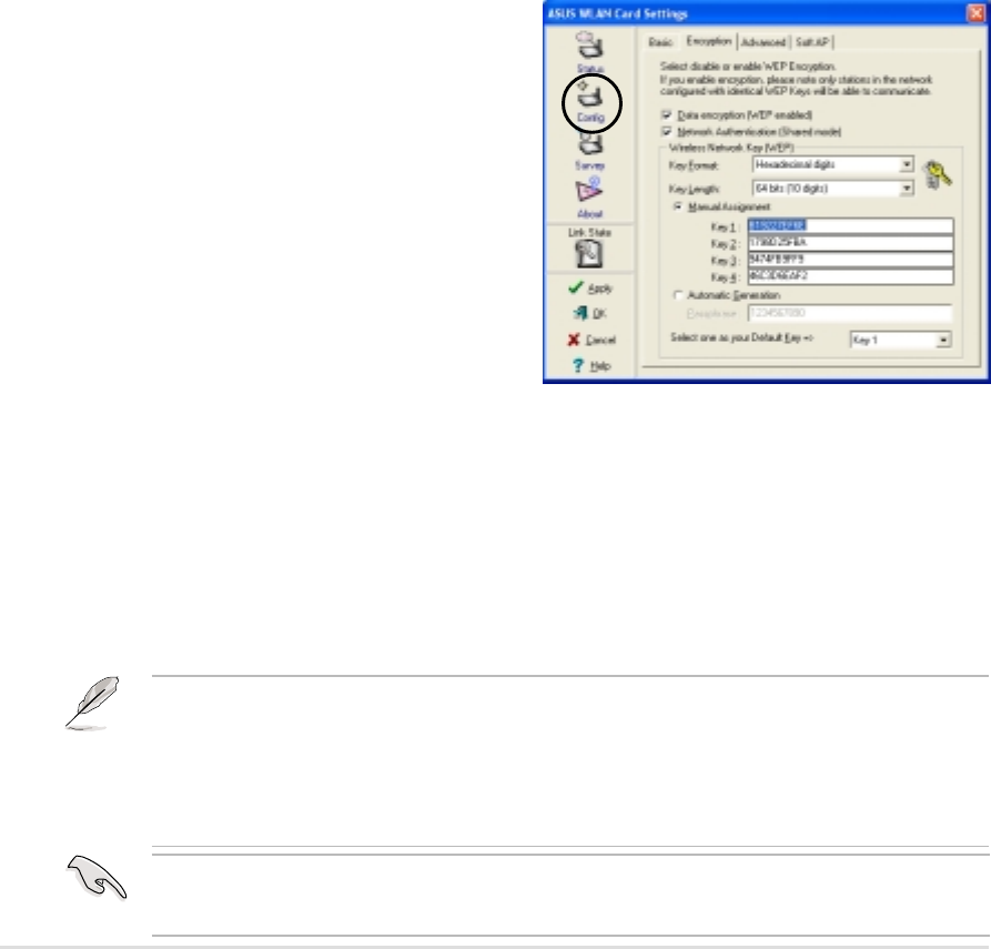
Config - EncryptionTab
Wireless data transmissions between
your WiFi-b™ and the AP are secured
using the Wired Equivalent Privacy
(WEP) encryption. Check the Data
encryption (WEP enabled) option to
assign the WEP keys.
Check the Network Authentication
(Shared Mode) option if you wish to use
a network key to authenticate a preferred
wireless network. Unchecking this option
allows the network to operate on an
Open System mode.
Key Format allows you to set a hexadecimal digit or ASCII character WEP key.
Key Length allows you to choose a 64-bit or a 128-bit WEP key. A 64-bit
encryption contains 10 hexadecimal digits or 5 ASCII characters. A 128-bit
encryption contains 26 hexadecimal digits or 13 ASCII characters.
64-bit and 40-bit WEP keys use the same encryption method and can interoperate
on wireless networks. This lower level of WEP encryption uses a 40-bit (10
hexadecimal digits assigned by the user) secret key and a 24-bit Initialization Vector
assign by the WiFi-b™. 104-bit and 128-bit WEP keys use the same encryption
method.
Network Name - Displays the network SSID. The network SSID is a string use to
identify a wireless LAN. Assign different SSIDs to segment the wireless LAN and
increase network security. Set the SSID to a null string to allow your station to
connect to any available access point. Null string may not be used in Ad Hoc
mode.
Channel. In Infrastructure mode, WiFi-b™ automatically tunes in to the access
point channel. In Ad Hoc mode, select a channel that is allowed for use in your
country/region. See the Appendix for channel information.
Data Rate. Select Fully Auto to allow WiFi-b to adjust to the most suitable
connection. You may also fix data transfer rates to 11, 5.5, 2 and 1 Mbps.
PS Mode. This field allows control of the WiFi-b™ card power saving features. The
CAM (Constantly Awake mode) is recommended for systems running on AC
power. Other options include MAX_PSP (Maximum Power Savings) and Fast_PSP
(Fast power-saving mode)
Others. Click the WEP or Advanced link to open the Encryption or Advanced
property tab sheet.
All wireless clients in a network must have identical WEP keys to communicate with
each other or with an access point.
Chapter 4: Utility information
4-7
Two ways to assign WEP keys
Manual Assignment. For a 64-bit encryption, enter 10 hexadecimal digits (0~9,
a~f, A~F) or 5 ASCII characters in each of the four WEP keys. For 128-bit
encryption enter 26 hexadecimal digits (0~9, a~f, A~F) or 13 ASCII characters in
each of the four WEP keys.
Automatic Generation. Type a combination of up to 64 letters, numbers, or
symbols in the Passphrase field. The Wireless Settings utility uses an algorithm to
generate four WEP keys based on the typed combination.
•After assigning the WEP keys, click APPLY to save and activate the encryption.
Manually assigned encryptions are more secure than automatically generated
encryptions.
•Use Manual Assignment instead of Automatic Generation if you are not sure
whether other wireless clients use the same algorithm as that of WiFi-b™.
•Keep a record of the WEP encryption keys.
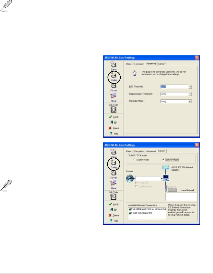
Config - Advanced
The Advanced tab displays the WiFi-b™
card advance settings. It is
recommended that you do not make any
changes on these settings.
Config - Soft AP
The Soft AP tab displays the Internet
Connection Sharing (ICS) and bridge
features of the WiFi-b™ card.
The Soft AP tab appears only on
systems running on Windows
®
XP.
SoftAP/STA Mode. This field allows you
to select the WiFi-b™ card mode. Select
Station Mode if you wish to connect to an
access point or to other wireless devices
(Ad Hoc mode). Select SoftAP Mode to configure your computer as a soft access
point. Fields in the network diagram are enabled when Soft AP mode is selected.
4-8
ASUS WiFi-b™ Card
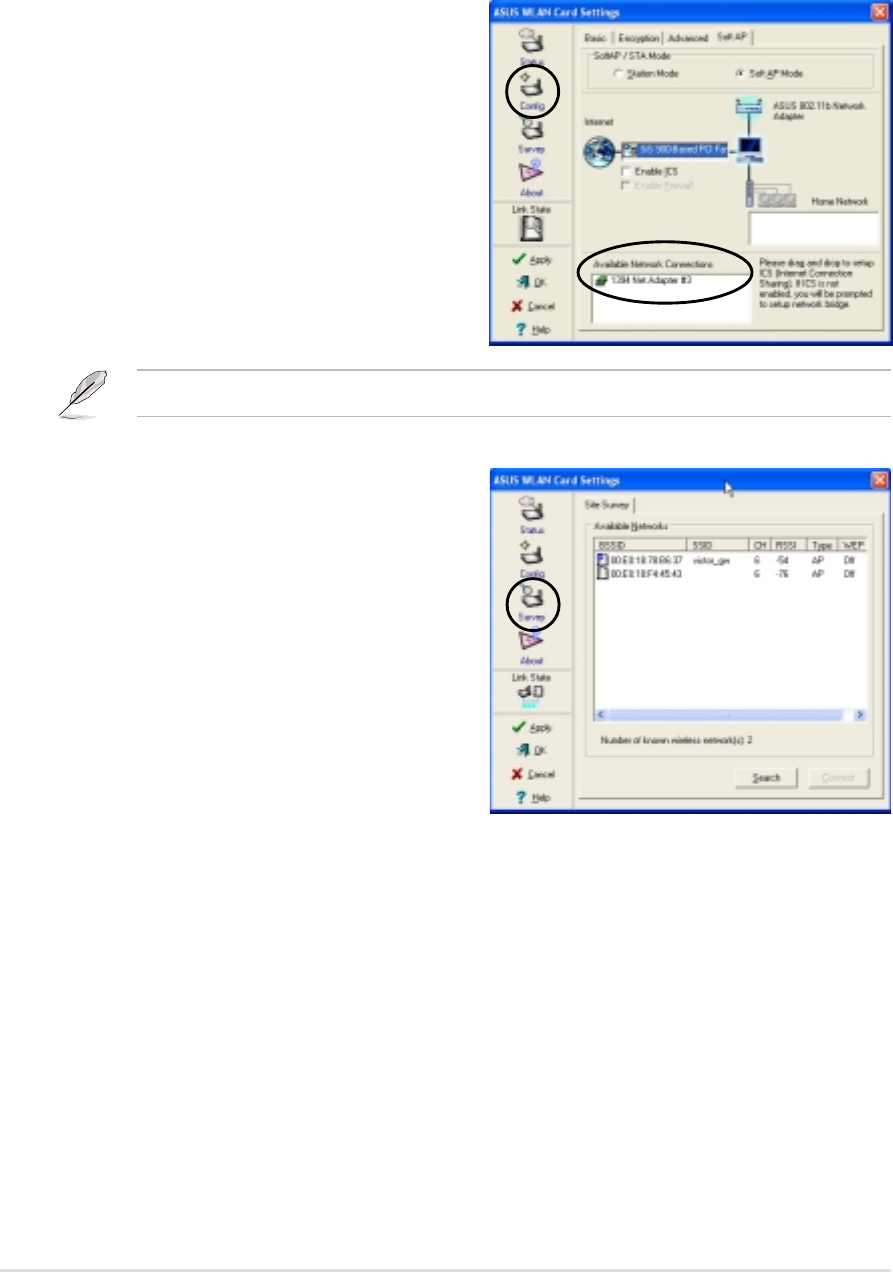
Site Survey
The Site Survey tab displays the
available networks within the WiFi-b™
range. The following network settings are
displayed:
BSSID - The IEEE MAC address of the
available wireless networks.
SSID - SSID (service set identifier) of the
network.
CH - Direct sequence channel used by
the network.
RSSI - Received Signal Strength Indicator (RSSI) in dBm.
Type - wireless network mode. AP indicates an Infrastructure network type. STA
indicates an Ad Hoc network type.
WEP - shows whether a network has an enabled (On) or disabled (Off) WEP
encryption.
Select an available network and click Connect to establish connection. Click
Search to rescan available networks.
Enable ICS. This option activates after an available network connection is placed
in the Internet field. Check this option if you want to share a single Internet
connection with other computers in a wireless network. See page 4-16 for details.
When disabled, the available network connection on the Internet field is bridged
with the WiFi-b™ card. Refer to page 4-19 to setup a network bridge.
Enable Firewall. This option is active
when ICS is enabled. Check this item to
activate the firewall and prevent
unauthorized access to your home or
small office network.
Available Network Connections. This
field displays all available network
connections in the host computer. To
enable Internet Connection Sharing
(ICS), drag the network connection to the
Internet box, then click Apply.
See section 4.4.2 “Soft Access Point (Soft AP) Mode” for details.
Chapter 4: Utility information
4-9
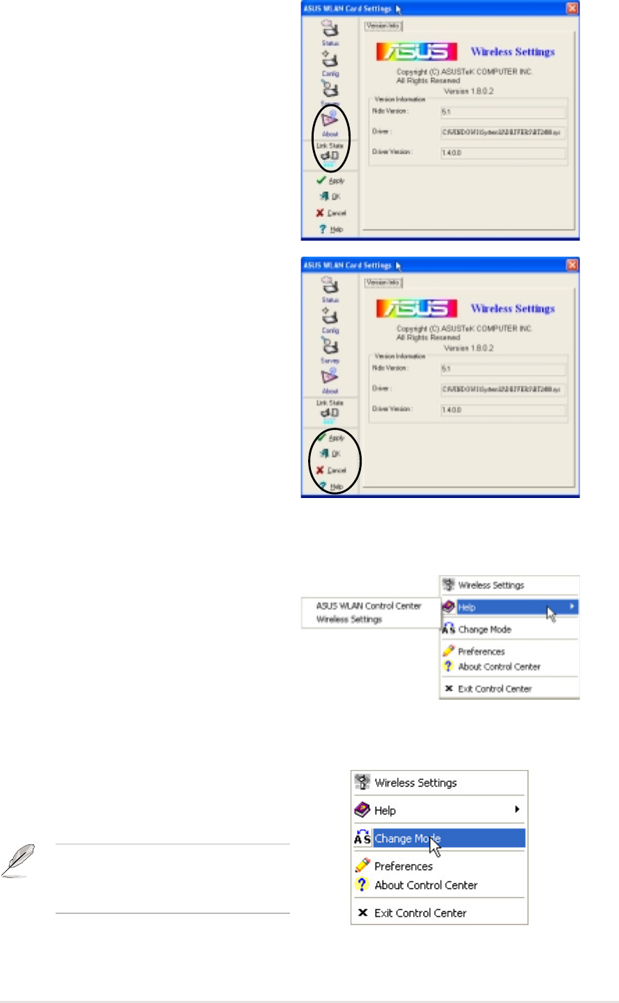
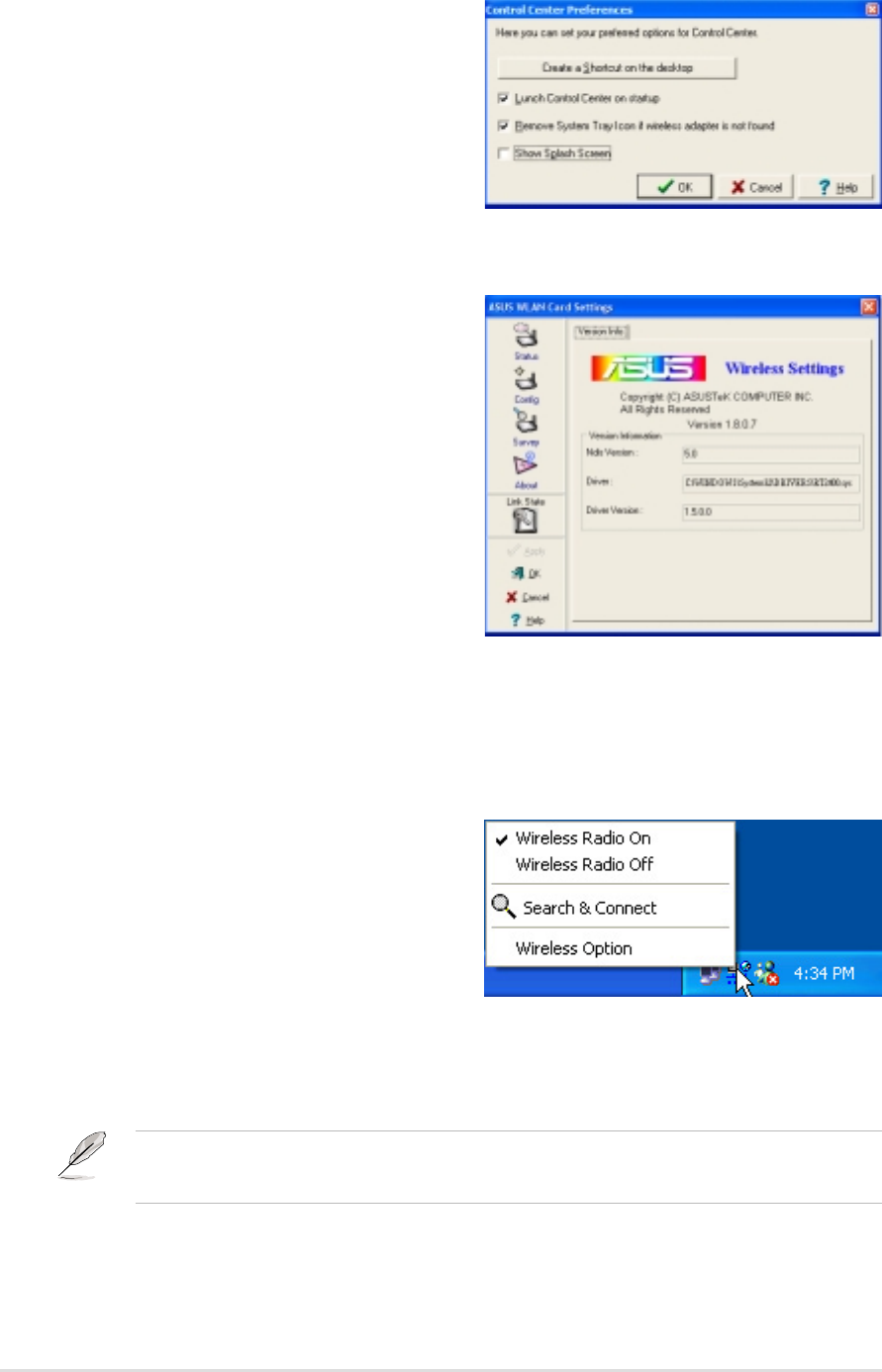
About
Click the About icon to view the software
version, driver version, and copyright
information.
Link State
Displays the current connection status of
the WiFi-b™ card to the AP or to other
Wi-Fi devices.
Command icons
Apply. Click to apply the changes made
on WiFi-b™ configuration and settings.
OK. Click to close the Wireless Settings
utility window.
Cancel. Click to cancel any changes
made on WiFi-b™ configuration or
settings. Clicking Cancel closes the
Wireless Settings utility window.
Help. Click to display the help menu.
4.2.2 Help Menu
The Control Center utility has a Help
menu to guide you in using the Control
Center and Wireless Settings utilities.
Right-click the Control Center icon, then
select Help. Select a utility to display its
help window.
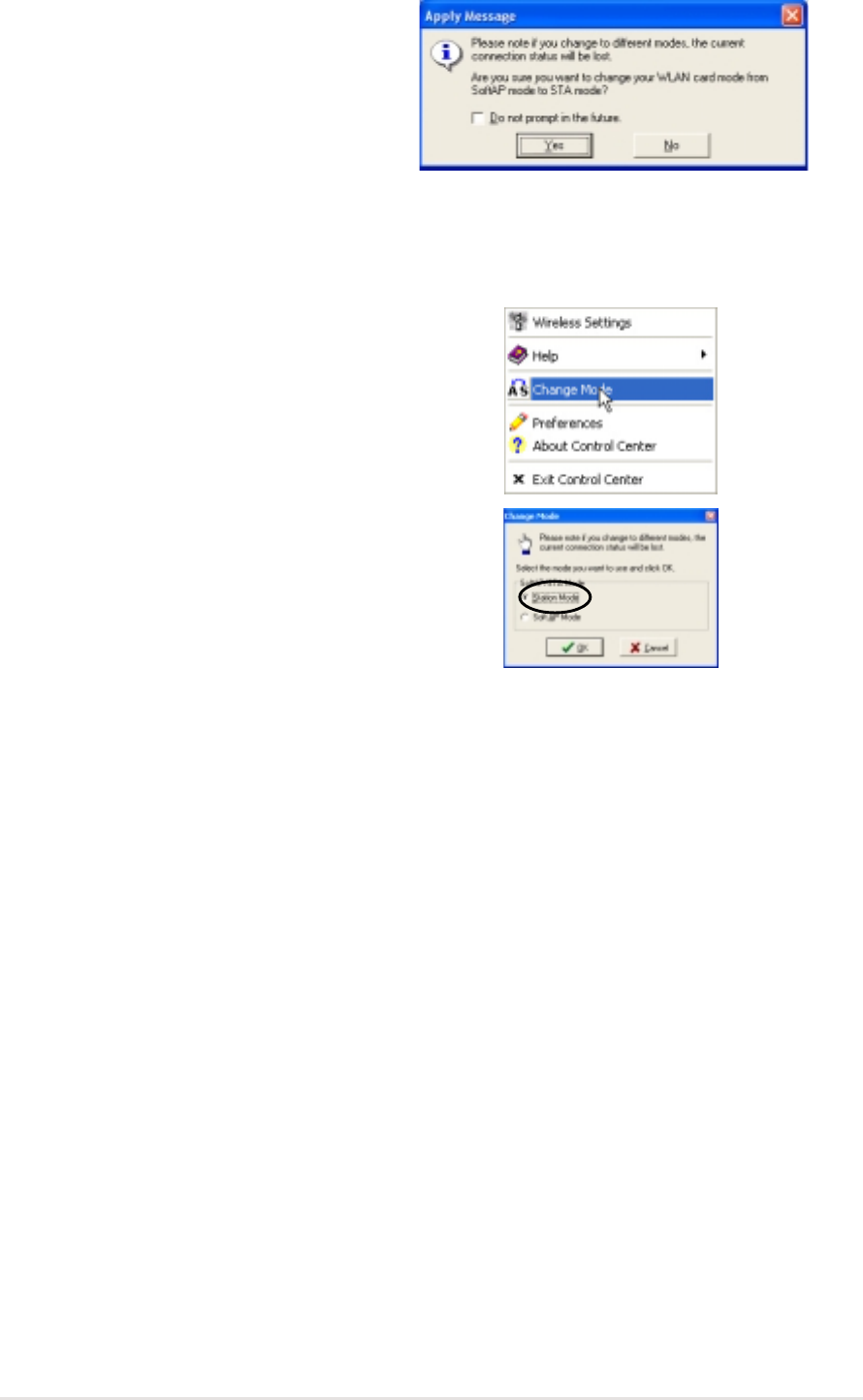
4.2.3 Change Mode
The Change Mode menu allows you to
set the WiFi-b™ card in a Station (STA)
or soft Access Point (AP) mode.
See page 4-13 “Soft Access Point
(Soft AP) Mode” for details on
theWiFi-b™ card soft AP function.
4-10
ASUS WiFi-b™ Card
4.3 Control Center Left-click menu
Left-clicking the Control Center icon displays the Left-Click Menu. The options are
described below.
Wireless Radio On – Turns the WiFi-b™
radio ON.
Wireless Radio Off – Turns the
WiFi-b™ radio OFF.
Search & Connect – View available
wireless networks within range.
Wireless Option – Sets your Windows
®
XP wireless networking environment.
See page 18 for details.
The Control Center Left-click menu is available only when WiFi-b™ is set to Station
Mode (STA).
4.2.5 About Control Center
The About Control Center menu
displays the software and drivers version,
and copyright information.
4.2.4 Preferences
The Preferences window allows you to
customize the Control Center Utility
settings.
Chapter 4: Utility information
4-11
4.4 Configuring WiFi-b
™
by Wireless Settings utility
The Wireless Settings utility allows you to set your WiFi-b™ card in Station (STA)
or Soft Access Point (Soft AP) mode. In STA mode, your WiFi-b™ connects to an
access point to access a wireless network or the Internet. In Soft AP mode, your
WiFi-b™ transmits and receives signals to and from other WiFi devices in a
wireless network. The Soft AP feature is available only on systems running on
Windows
®
XP.
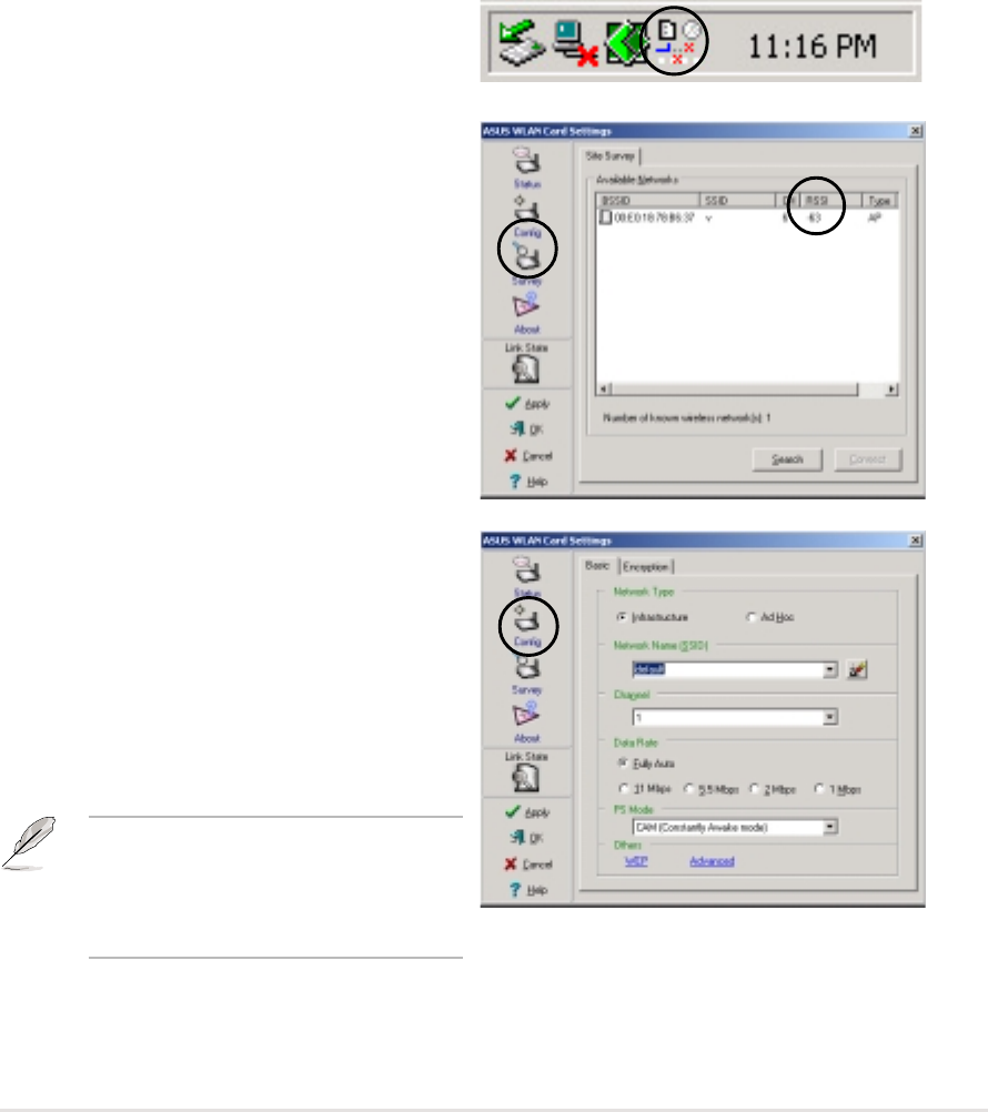
4.4.1 Station Mode (STA)
Follow these instructions to set your WiFi-b in Station (STA) mode.
Windows
®
98SE/ME/2000 OS
1. Launch the Wireless Settings utility
by double-clicking the Control
Center icon in the Windows taskbar.
2. Click the Survey icon from the
property window to display the
available access points or other Wi-Fi
device.
3. Select the AP with the best signal
quality by referring to the RSSI
column. The higher the RSSI, the
better the signal quality.
4. Click the Config icon, then select the
Basic tab to configure your network.
Select Infrastructure, then click
Apply.
5. Set the WiFi-b™ Network Name
(SSID). The WiFi-b™ SSID must be
identical with the SSID of the
selected AP.
NOTE. Setting the SSID to a null
string allows your WiFi-b™ to
connect to any available access
point.
4-12
ASUS WiFi-b™ Card
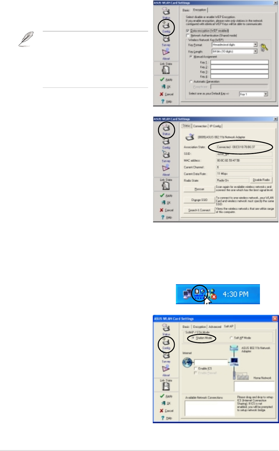
6. Click the Encryption tab to set the
WiFi-b™ encryption if the selected
AP has an enabled WEP encryption.
Refer to the Site Survey window to
determine whether the selected AP
has an enabled (ON) or disabled
(OFF) WEP encryption. Refer to page
4-6 on how to configure WEP
encryptions.
Windows
®
XP OS
Do any of the following to set your WiFi-b™ in station mode:
Enter the Wireless Settings utility
1. Double-click the Control Center icon
in the Windows taskbar to open the
Wireless Settings utility.
2. Click the Config icon in the property
window, then select the Soft AP tab.
Select Station Mode.
7. To check if WiFi-b™ is associated
with the selected AP, click the Status
icon in the property window, then
select the Status tab. Look for the
Associated State field to confirm.
Chapter 4: Utility information
4-13
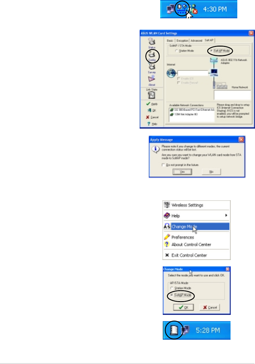
4.4.2 Soft Access Point Mode (Soft AP)
You may set the WiFi-b™card in soft access point mode. As soft AP, WiFi-b™ can
support up to 31 wireless clients in a home or small office network.
System requirements
Before setting your WiFi-b™ as soft AP make sure your system meets the
following requirements:
•Windows
®
XP operating system
Wireless clients in home or small office network must have:
•An installed IEEE 802.11b compliant network interface card
•Windows
®
98SE/ME/2000/XP operating system
Use the Change Mode menu
1. Right-click the Control Center icon in
the Windows taskbar to display the
right-click menus. Select Change
Mode.
3. Follow steps 2 to 7 of the previous section to set the WiFi-b™ in STA mode.
3. The following confirmation dialog box
appears when you switch from Soft
AP mode to Station Mode. Click Yes.
2. Select Station Mode when the
Change Mode window appears. Click
OK.
4. Follow steps 2 to 7 of the previous section to set the WiFi-b™ in STA mode.
4-14
ASUS WiFi-b™ Card
Use the Change Mode menu
1. Right-click the Control Center icon
in the Windows taskbar to display the
right-click menus. Select Change
Mode.
3. The Soft AP icon replaces the
Control Center utility icon in the
Windows
®
taskbar.
Setting your WiFi-b™ in Soft Access Point (Soft AP) mode
Do any of the following to set your WiFi-b™ in soft AP mode:
Enter the Wireless Settings utility
1. Double-click the Control Center icon
in the Windows taskbar to open the
Wireless Settings utility.
2. Click the Config icon in the property
window of the Wireless Settings
utility, then select the SoftAP tab.
Select Soft AP Mode, then click
Apply.
2. Select Soft AP Mode when the
Change Mode window appears. Click
OK.
3. A confirmation window appears click
Yes.
Chapter 4: Utility information
4-15
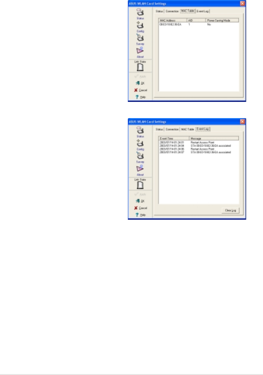
Other Soft AP settings
When in Soft AP mode, two additional tabbed property sheets are added to the
Status settings of the Wireless Settings utility.
MAC Table
The MAC Table tab displays the MAC
address of a wireless device connected
to the soft AP.
AID - shows the Association ID of a
wireless device connected to the soft AP.
Power Saving Mode - displays the
Power Saving Mode used by the wireless
device connected to the soft AP.
Event Log
The Event Log tab displays detected
system events including the date and
time of the event and event type. Click
Clear Log to clear the event log window.
4-16
ASUS WiFi-b™ Card
4.5 Internet Connection Sharing (ICS)
After setting the WiFi-b™ card on Soft AP mode, you may enable Internet
Connection Sharing (ICS). ICS is a Windows
®
XP feature allowing several
computers in a wired or wireless network to share a single Internet connection.
With ICS, other wireless clients in a home or small office network rely on the
WiFi-b™ for Internet access. Follow these instructions to enable ICS.
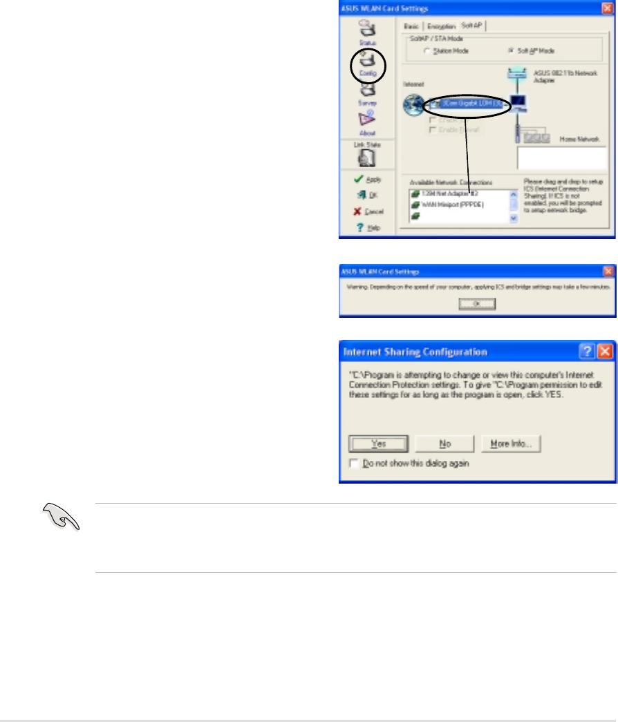
4.5.1 Connect to the Internet using a broadband
connection that is always on
To enable ICS if your computer connects to the Internet using a broadband that is
always on:
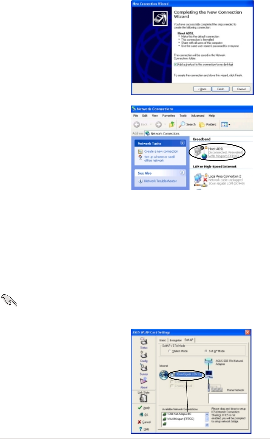
1. Open the Wireless Settings utility.
Select Config from the property
window, then select the Soft AP tab.
2. Select the built-in 3Com Gigabit LAN
connection from the Available
Network Connections field, then
drag it to the Internet field.
3. Check Enable ICS and Enable
Firewall, then click Apply.
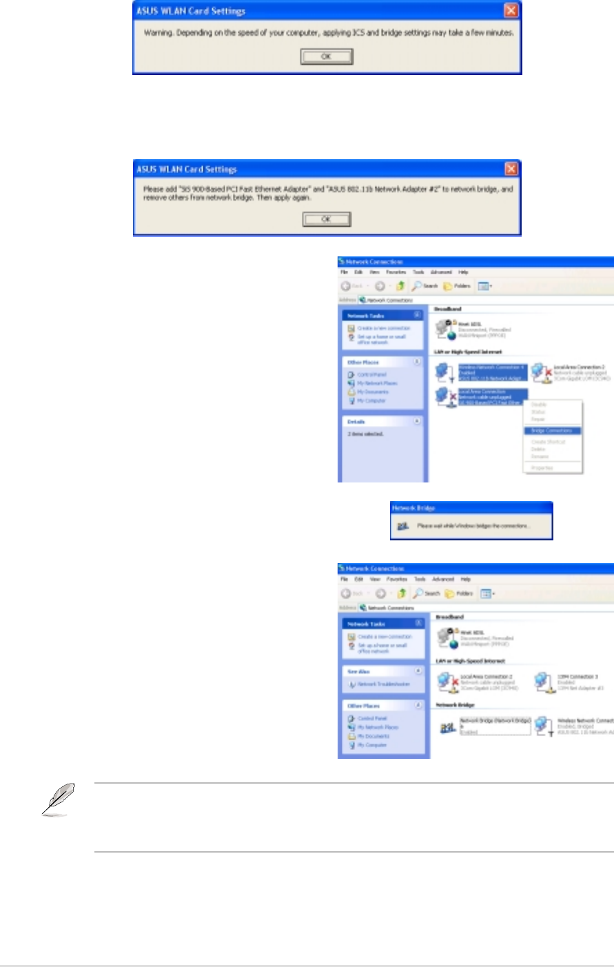
4. Click OK when this dialog box
appears.
5. An Internet Sharing Configuration
dialog box appears. Click Yes. The
Internet network connection and the
WiFi-b™ card is bridged. See section
4.6 “Network Bridge” for details.
Wireless clients must be set to Infrastructure network type and STA (station) mode to
connect to the Internet via the soft AP. The SSID and WEP keys of client computers
must be identical with that of the soft AP.
Chapter 4: Utility information
4-17
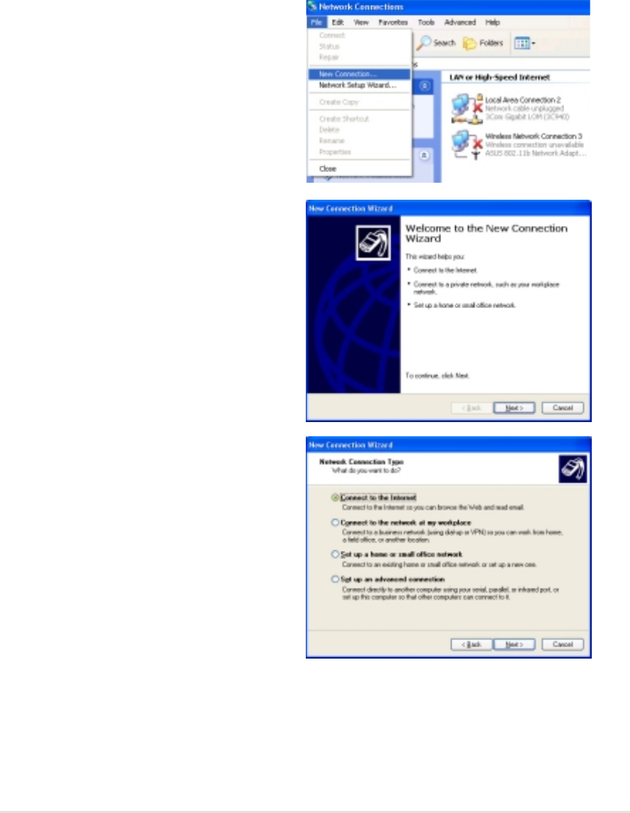
3. A New Connection Wizard appears.
Click Next.
4. When prompted, select the Network
connection type. Select Connect to
the Internet, then click Next.
4.5.2 Connect to the Internet using a broadband or
dial-up connection that requires an account
If the host computer with the WiFi-b™ card connects to the Internet using a
broadband or dial-up connection that requires an account, create a broadband
(PPPoE) or dial-up network connection using the Windows
®
XP interface before
enabling ICS.
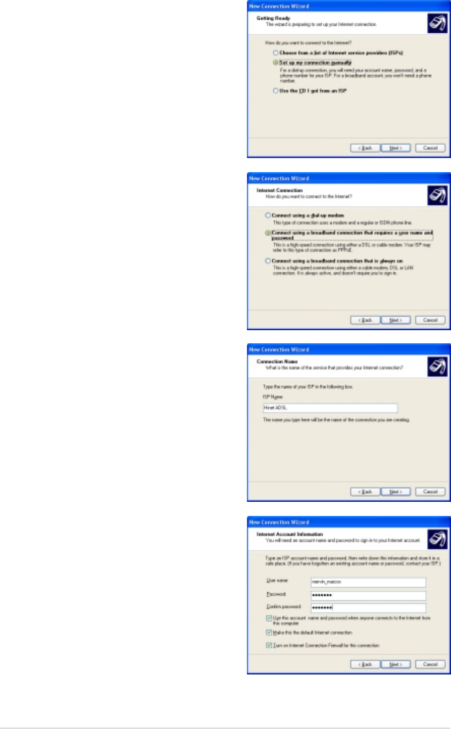
To create a broadband connection:
1. Open the Network Connections
window by clicking Start > Connect
To > Show all connections from the
Windows
®
desktop.
2. Click File from the menu, then select
New Connection.
4-18
ASUS WiFi-b™ Card
5. Select Set up my connection
manually, then click Next.
6. Depending on your network setup,
select Connect using a broadband
connection that requires a user
name and password or Connect
using a dial-up modem, then click
Next.
7. Enter the ISP name, then click Next.
8. Enter the user name and password
assigned by your ISP, then check all
settings below the user name and
password fields. Click Next.
Chapter 4: Utility information
4-19
9. Click Finish when the wizard
completes creating the connection.
10. The created connection is displayed
in the Network Connections
window. Return to the Wireless
Settings utility. Select the created
connection from the Available
Network Connections, then drag it to
the Internet field. Refer to the steps
in section 4.5.1 to enable ICS.
4.6 Network Bridge
Host computers with multiple network adapters may use the network bridge
function to connect several LAN segments. A LAN segment is a physical
connection between a host computer and a client computer. Network bridging is a
cost-effective method of connecting LAN segments since it does not require
expensive hardwares such as routers and technical expertise for configuring
Internet protocol (IP) addresses. Network bridge is essential in enabling ICS
among wireless clients in a home network.
You must have Administrator privileges before you could create a network bridge.
To bridge a wired network connection to the WiFi-b™:
1. Open the Wireless Settings utility.
Select Config from the property
window, then select the Soft AP tab.
2. Select a network connection from the
Available Network Connections box,
then drag the connection to the
Internet field. Click Apply.
4-20
ASUS WiFi-b™ Card
4. The Wireless Settings utility displays the wired and wireless network
connections to be added in a network bridge based on your configuration.
Write down these network connections in a piece of paper. Click OK.
5. Select the network connections to be
bridged. Press the Control key while
clicking the network connection icons
to select. Right-click on any selected
network icon to open a drop-down
menu. Select Bridge Connections.
7. The bridged network connections are
displayed in the Network
Connections window.
6. Wait while the selected network
connections are bridged.
Only LAN connections may be bridged with the WiFi-b™ card. The Wireless
Settings utility will instruct you to change your settings if you bridge a non-LAN
connection with the WiFi-b™.
3. A warning message appears. Click OK.

Appendix
The appendix contains sections for
troubleshooting and information on
IEEE 802.11b channels and frequencies.

A-2
ASUS WiFi-b™ Card
A.1 Troubleshooting
My computer does not recognize
the installed WiFi-b™ card. Verify if the WiFi-b™ card drivers are
properly installed by following these
instructions:
1. Open the Control Panel window
from the Windows
®
desktop.
2. Double-click on the System icon.
3. Windows
®
98SE/Me users: Select
the Device Manager tab.
Windows
®
2000/XP users: Select
the Hardware tab then click the
Device Manager button.
4. Click the “+” symbol preceeding
the Network Adapters item, then
check the ASUS 802.11b
Network Adapter or ASUS
802.11g Network Adapter item.
A yellow exclamation point or a
red plus sign preceeding the
network adapter means that the
device driver is not properly
installed. Re-install the WiFi-b™
card driver following the
instructions below.
Problem Action
This troubleshooting guide provides answers to some common problems which you
may encounter while installing and/or using ASUS Wireless LAN card products.
These problems requires simple troubleshooting that you can perform by yourself.
Contact the Wireless LAN Technical Support if you encounter problems not
mentioned in this section.
A yellow exclamation point or a
red plus sign appears on the
ASUS 802.11b Network Adapter
or ASUS 802.11g Network
Adapter item.
The WiFi-b™ driver is not properly
installed. Follow these instructions to
uninstall and re-install the driver.
1. Insert the Support CD into the
CD-ROM drive.
2. When the ASUS WiFi-b™
installation window appears, click
“Uninstall ASUS WLAN Card
Utilities/Driver” option.

Appendix
A-3
3. Restart your computer and repeat
the WiFi-b™ software installation
following the instructions
contained in this User Guide.
Problem Action
I cannot connect to an Access
Point. •Check if the Network Type of the
WiFi-b™ card is set to
Infrastructure mode.
•Check if the WiFi-b™ has the
same Service Set Identifier
(SSID) as that of the AP.
•Check if the WiFi-b™ card and the
AP have the same Encryption. If
WEP encryption is enabled, set
the same WEP keys for the
WiFi-b™ and the AP.
•Check if the MAC address of the
WiFi-b™ card is added in the AP
Authorization Table. Inquire this
with your LAN administrator.
•There is poor signal reception.
Re-orient the WiFi-b™ antenna.
I can connect to an Access Point
but I cannot connect to the
Internet.
•Check if the WiFi-b™ card and the
AP have the same Encryption. If
WEP encryption is enabled, set
the same WEP keys for the
WiFi-b™ and the AP.
•Make sure the network protocol
parameters (IP address, subnet
mask, gateway, and DNS) of your
computer are correctly set.
•Check the proxy settings of the
web browser.

A-4
ASUS WiFi-b™ Card
Problem Action
I cannot connect to another
station (computer with a
wireless LAN device).
•Check if the Network Type of the
WiFi-b™ card is set to Ad Hoc
mode.
•Check if the WiFi-b™ has the
same Service Set Identifier
(SSID) with that of the other
station.
•Check if the WiFi-b™ card and the
other station have the same
Encryption. If WEP encryption is
enabled, set the same WEP keys
for the WiFi-b™ and the AP.
•There is poor signal reception.
Place the WiFi-b™ antenna
nearer to the station.
I cannot connect to other
computers linked via an Access
Point or Ad Hoc network.
•Check if the WiFi-b™ card and the
other APs and/or clients have the
same Encryption. If you enable
WEP encryption, you must set the
same WEP keys for the WiFi-b™
card and the other AP/s and/or
clients.
•Check the TCP/IP settings (IP
address, subnet mask, gateway,
and DNS) of your computer.
•Enable file and printer sharing in
each client computer to allow file
sharing.
I always have poor link quality
and low signal. Observe the following to achieve better
link quality and stronger signal:
•Keep the WiFi-b™ away from
microwave ovens and large metal
objects to avoid radio interference.
•Reorient the WiFi-b™ antenna.
•Shorten the distance between the
WiFi-b™ card and the AP/station.

Appendix
A-5
Channel Center Channel Center
Frequency Frequency
1 2.412 GHz 8 2.447 GHz
2 2.417 GHz 9 2.452 GHz
3 2.422 GHz 10 2.457 GHz
4 2.427 GHz 11 2.462 GHz
5 2.432 GHz 12 2.467 GHz
6 2.437 GHz 13 2.472 GHz
7 2.442 GHz 14 2.484 GHz
A.2 Channels
The IEEE 802.11b standard for Wireless LAN allocated the 2.4 GHz frequency
band into 14 overlapping operating channels. Each channel corresponds to a
different set of frequencies. The table below shows the center frequencies of each
channel.
The number of channels available for the WiFi-b™ varies by country/region. Refer
to the table below to determine the number of channels available in your location.
Country/Region (Regulating Body) Available Channels
Australia (ACA) Channels 1 to 13
Belgium (RTT&E/EMC/LVD) Channels 1 to 13
Bulgaria (RTT&E/EMC/LVD) Channels 1 to 13
Canada (CSA/cUL 950 3rd Edition) Channels 1 to 11
China (MII) Channels 1 to 11
Cyprus (RTT&E/EMC/LVD) Channels 1 to 13
Czech Republic (RTT&E/EMC/LVD) Channels 1 to 13
Denmark (RTT&E/EMC/LVD) Channels 1 to 13
Finland (RTT&E/EMC/LVD) Channels 1 to 13
France (RTT&E/EMC/LVD) Channels 1 to 13
Germany (RTT&E/EMC/LVD) Channels 1 to 13
Greece (RTT&E/EMC/LVD) Channels 1 to 13
Hong Kong (OFTA) Channels 1 to 13
Hungary (RTT&E/EMC/LVD) Channels 1 to 13
Iceland (RTT&E/EMC/LVD) Channels 1 to 13
Ireland (RTT&E/EMC/LVD) Channels 1 to 13
Italy (RTT&E/EMC/LVD) Channels 1 to 13
Japan (TELEC) Channels 1 to 14
(continued next page)
If several WiFi devices are operating in the same vicinity, the distance between the
center frequencies of channels used must be at least 25 MHz to avoid interference.

A-6
ASUS WiFi-b™ Card
Channels 1,6 and 11 are independent and do not overlap each other. It is
recommended to tune your WiFi-b™ card to these channels.
Country/Region (Regulating Body) Available Channels
Luxembourg (RTT&E/EMC/LVD) Channels 1 to 13
Malaysia (SIRIM/CMC) Channels 1 to 13
Mexico Channels 9 to 11
Netherlands Antilles (RTT&E/EMC/LVD) Channels 1 to 13
Netherlands/Holland (RTT&E/EMC/LVD) Channels 1 to 13
New Zealand (PTC) Channels 1 to 13
Norway (RTT&E/EMC/LVD) Channels 1 to 13
Portugal (RTT&E/EMC/LVD) Channels 1 to 13
Saudi Arabia Channels 1 to 13
Singapore Channels 1 to 13
South Korea (KS) Channels 1 to 13
Spain (RTT&E/EMC/LVD) Channels 1 to 11
Sweden (RTT&E/EMC/LVD) Channels 1 to 13
Switzerland (RTT&E/EMC/LVD) Channels 1 to 13
Taiwan (DGT) Channels 1 to 11
Turkey (TTAS) Channels 1 to 13
United Kingdom (RTT&E/EMC/LVD) Channels 1 to 13
United States (FCC) Channels 1 to 11