ASUSTeK Computer PLX32M HomePLUG AV Ethernet adapter User Manual User s Manual
ASUSTeK Computer Inc HomePLUG AV Ethernet adapter User s Manual
UserManual.wiki
>
ASUSTeK Computer
>
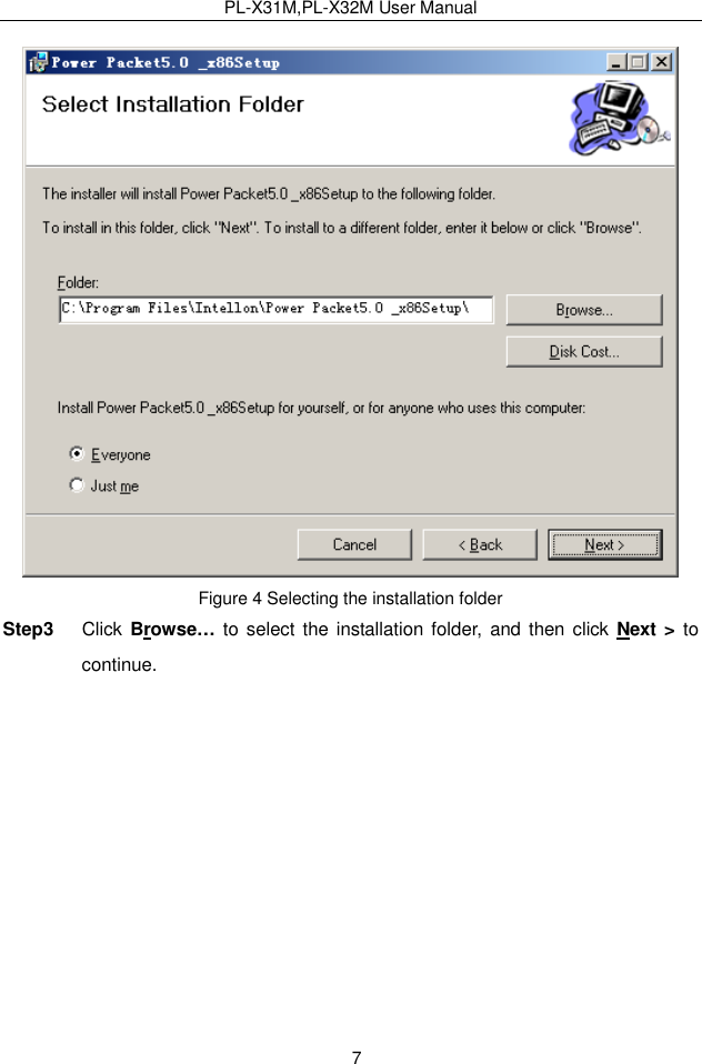
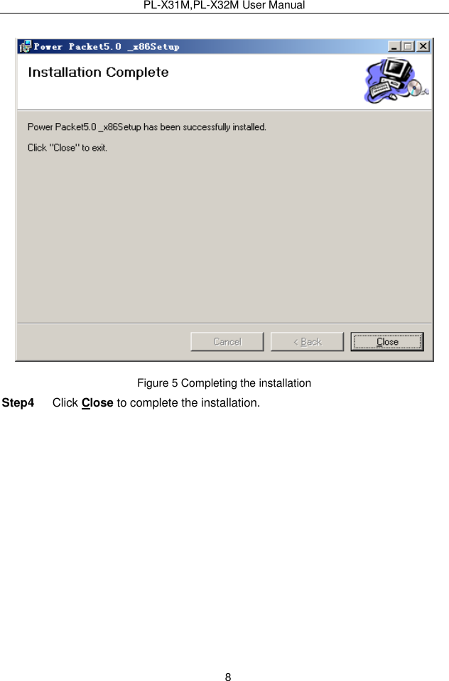
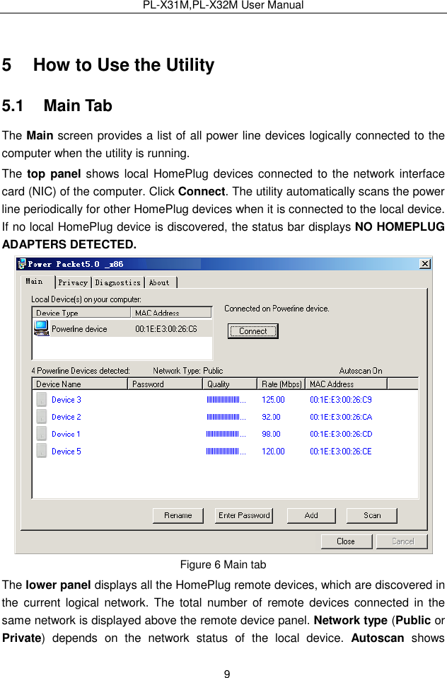
PLX32M User Manual
User Manual
Navigation menu
Upload a User Manual
Namespaces
Wiki Guide
HTML
PDF
Info
Views
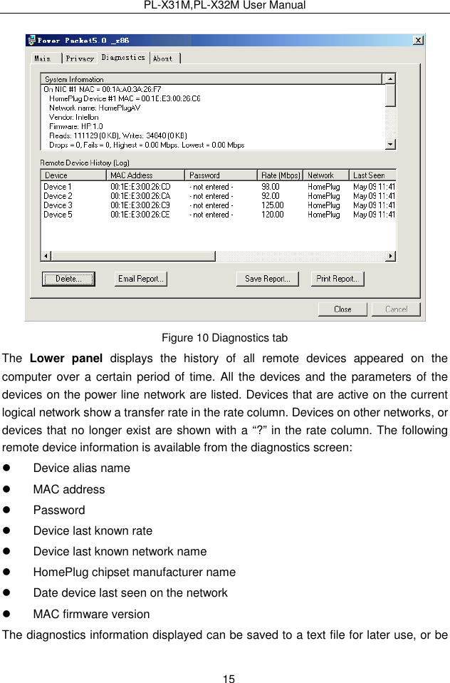
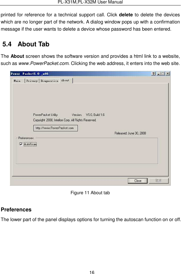
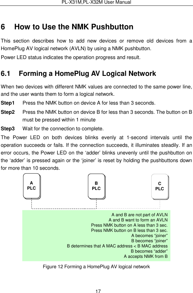
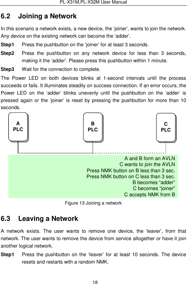
User Manual
Discussion / Help
Navigation