ASUSTeK Computer R1E NOTEBOOK P.C. User Manual R1E UserMan part 2
ASUSTeK Computer Inc NOTEBOOK P.C. R1E UserMan part 2
Contents
- 1. USERS MANUAL 1
- 2. USERS MANUAL 2
USERS MANUAL 2
31
Getting Started 3
Switches
Switches and Status Indicators
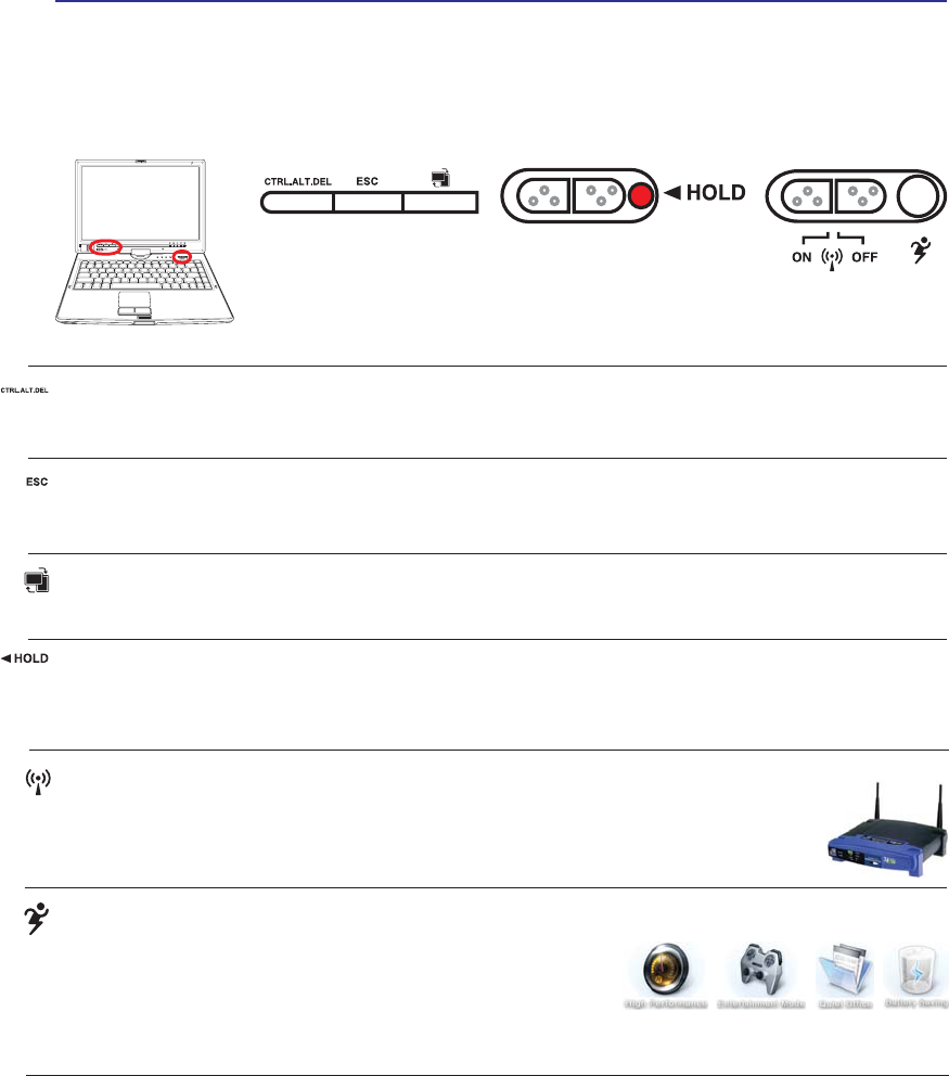
Power4Gear eXtreme Key
The Power4Gear eXtreme key toggles power savings between
various power saving modes. The power saving modes control
many aspects of the Notebook PC to maximize performance versus
battery time. Applying or removing the power adapter will automatically switch the system between AC
mode and battery mode. The selected mode is shown on the display.
Wireless Switch
Wireless Models Only: Toggles the internal wireless LAN or Bluetooth (on selected models)
ON or OFF with an on-screen display. When enabled, the corresponding wireless indicator
will light. Windows software settings are necessary to use the wireless LAN or Bluetooth.
CTRL.ALT.DEL Key
Pressing this key emulates the key combinations on the keyboard. Used for logging into Windows.
Rotate Screen Key
For use with tablet PC mode. Press once to rotate the screen clock-wise.
Hold Key
For use with tablet PC mode. When enabled, the keys on the display panel will be disabled in case they are
accidentally pressed while using the tablet PC pen on the display panel.
ESC Key
Pressing this key here is the same as on the keyboard.
32
3 Getting Started
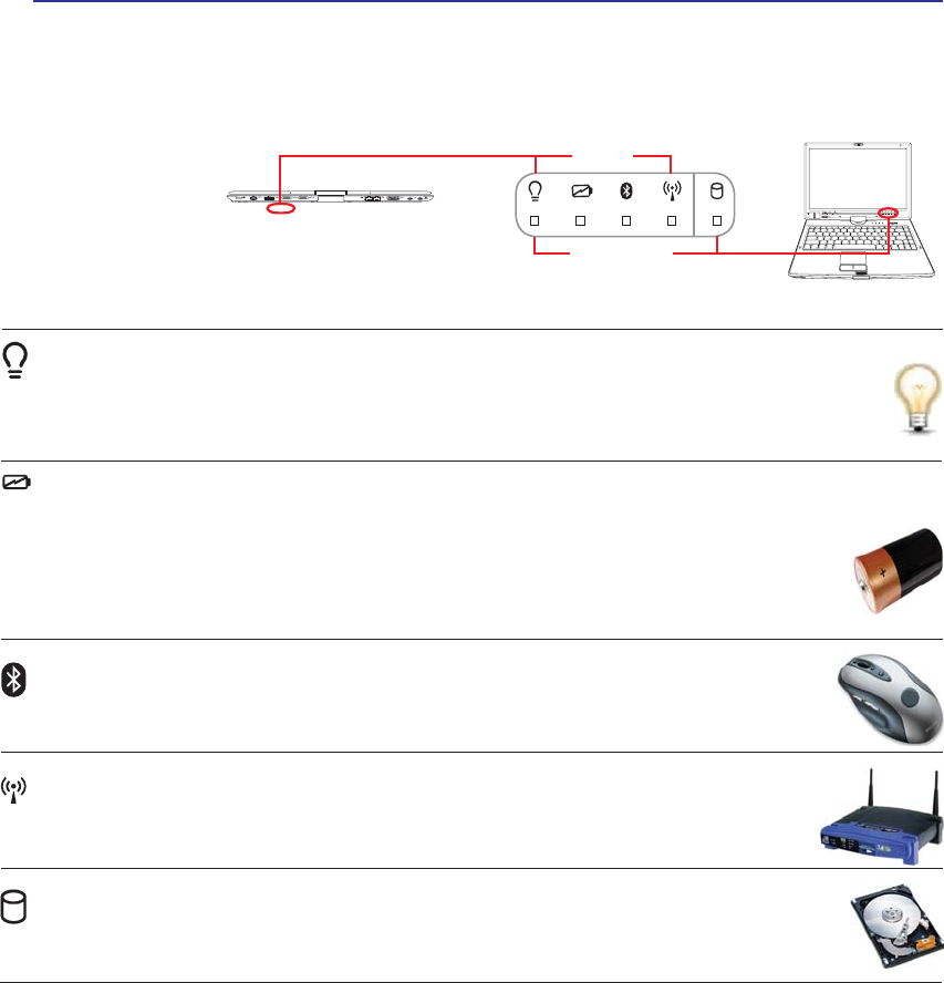
Status Indicators
Battery Charge Indicator
The battery charge indicator shows the status of the battery’s power as follows:
ON: The Notebook PC’s battery is charging when AC power is connected.
OFF: The Notebook PC’s battery is charged or completely drained.
Blinking: Battery power is less than 10% and the AC power is not connected.
Power Indicator
The power indicator lights when the Notebook PC is turned ON and blinks slowly when the Note-
book PC is in the Suspend-to-RAM (Sleep) mode. This indicator is OFF when the Notebook PC
LVWXUQHG2))RULQWKH6XVSHQGWR'LVN+LEHUQDWLRQPRGH
Bluetooth Indicator
This is only applicable on models with internal Bluetooth (BT). This indicator will light to
show that the Notebook PC’s built-in Bluetooth (BT) function is activated.
Wireless LAN Indicator
This is only applicable on models with built-in wireless LAN. When the built-in wireless
LAN is enabled, this indicator will light. (Windows software settings are necessary.)
Switches and Status Indicators (cont.)
Drive Activity Indicator
Indicates that the Notebook PC is accessing one or more storage device(s) such as the hard
GLVN7KHOLJKWÁDVKHVSURSRUWLRQDOWRWKHDFFHVVWLPH
Outside
Display panel
Display panel and outside
33
Using the Notebook PC 4
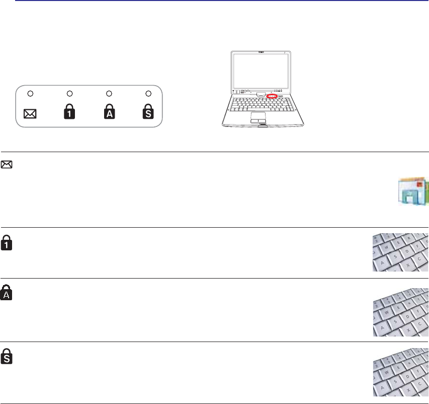
Email Indicator
Flashes when there is one or more new email(s) in your email program’s inbox. This func-
WLRQUHTXLUHVVRIWZDUHVHWXSDQGPD\QRWEHFXUUHQWO\FRQÀJXUHGRQ\RXU1RWHERRN3&7KLV
function is designed for Microsoft email software only and may not work with email software
from other companies.
Capital Lock Indicator
,QGLFDWHVWKDWFDSLWDOORFN>&DSV/RFN@LVDFWLYDWHGZKHQOLJKWHG&DSLWDOORFNDOORZVVRPH
of the keyboard letters to type using capitalized letters (e.g. A, B, C). When the capital
lock light is OFF, the typed letters will be in the lower case form (e.g. a,b,c).
Number Lock Indicator
,QGLFDWHVWKDWQXPEHUORFN>1XP/N@LVDFWLYDWHGZKHQOLJKWHG1XPEHUORFNDOORZVVRPH
of the keyboard letters to act as numbers for easier numeric data input.
Scroll Lock Indicator
,QGLFDWHVWKDWVFUROOORFN>6FU/N@LVDFWLYDWHGZKHQOLW6FUROOORFNDOORZVVRPHRIWKH
keyboard letters to act as direction keys in order to allow easier navigation when only a
part of the keyboard is required, such as for playing games.
Status Indicators
Switches and Status Indicators (cont.)
34
4 Using the Notebook PC
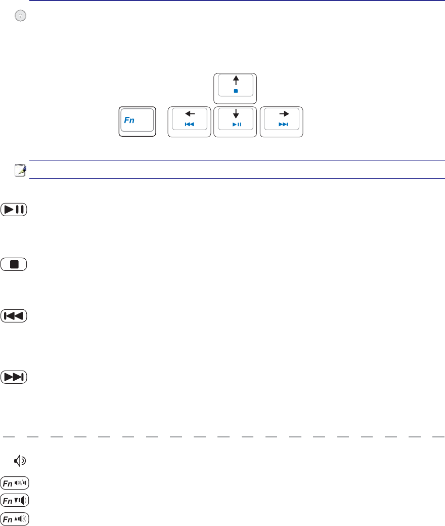
CD Play/Pause
During CD stop, EHJLQV&'SOD\
During CD play, SDXVHV&'SOD\
CD Stop
During CD stop:(MHFWVWKH&'WUD\
During CD play:6WRSV&'SOD\
CD Skip to Next Track (Fast Forward) & Audio Volume Up
During CD play, this button has two functions:
Track: Push once to skip to the next WUDFNGXULQJ&'SOD\LQJ
Audio: +ROGGRZQWRincrease audio volume.
Audio Volume Controls
Fn + Speaker Icons (F10): Toggles the audio volume ON and OFF
Fn + Down Speaker Icon (F11): 'HFUHDVHVWKHDXGLRYROXPH
Fn + Up Speaker Icon (F12): Increases the audio volume
Multimedia Control Keys (on selected models)
The multimedia control keys allows for convenient controlling of the multimedia application. The fol-
ORZLQJGHÀQHVWKHPHDQLQJRIHDFKPXOWLPHGLDFRQWURONH\RQWKH1RWHERRN3&
CD Skip to Previous Track (Rewind) & Audio Volume Down
During CD play, this button has two functions:
Track: 7KHÀUVWSXVKZLOOUHVWDUWWKHFXUUHQWWUDFN6HFRQGSXVKZLOOVNLSWRWKHprevious track.
Audio:+ROGGRZQWRdecrease audio volume.
Use the [Fn] key in combination with the arrow keys for CD control functions.

35
NOTE: Photos and icons in this manual are used for artistic purposes only and do not
show what is actually used in the product itself.
4. Using the Notebook PC
Pointing Device
Storage Devices
Expansion Card
Optical drive
Flash memory card reader
Hard disk drive
Memory (RAM)
Connections
Modem Connection
Network Connection
Wireless LAN Connection (on selected models)
Bluetooth Wireless Connection (on selected models)
Trusted Platform Module (TPM) (on selected models)
36
4 Using the Notebook PC
IMPORTANT! Do not use any objects in
SODFHRI\RXUÀQJHUWRRSHUDWHWKHWRXFK-
pad or else damage may occur to the
touchpad’s surface.
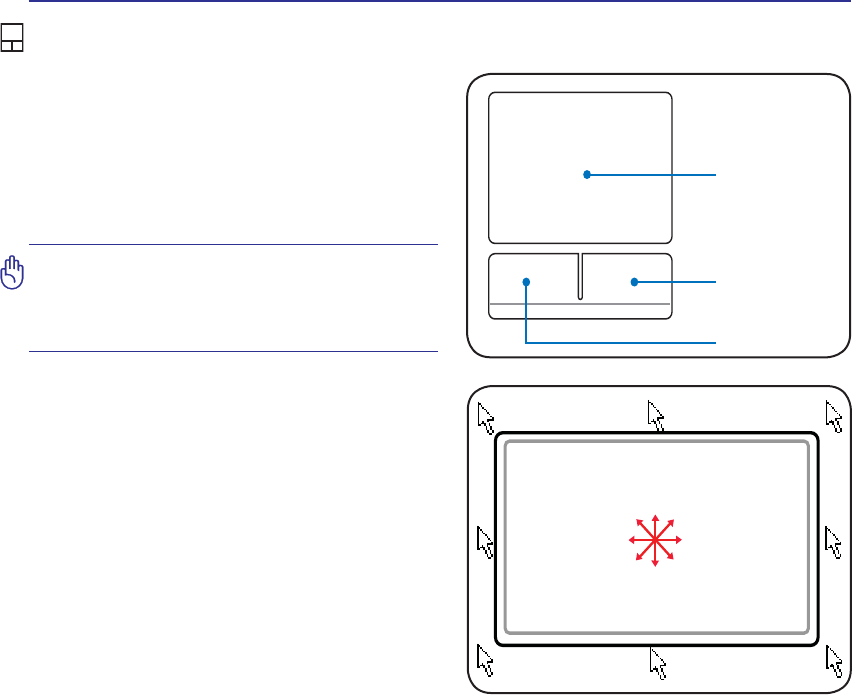
Pointing Device
The Notebook PC’s integrated touchpad pointing
device is fully compatible with all two/three-but-
ton and scrolling knob PS/2 mice. The touchpad is
pressure sensitive and contains no moving parts;
therefore, mechanical failures can be avoided. A
device driver is still required for working with some
application software.
Cursor
Movement
Right Click
Left Click
Using the Touchpad
/LJKWSUHVVXUHZLWKWKHWLSRI\RXUÀQJHULVDOOWKDWLV
required to operate the touchpad. Because the touch-
pad is electrostatic sensitive, objects cannot be used in
SODFHRI\RXUÀQJHUV7KHWRXFKSDG·VSULPDU\IXQFWLRQ
is to move the cursor around or select items displayed
RQWKHVFUHHQZLWKWKHXVHRI\RXUÀQJHUWLSLQVWHDGRI
a standard desktop mouse. The following illustrations
demonstrate proper use of the touchpad.
Moving The Cursor
3ODFH\RXUÀQJHULQWKHFHQWHURIWKHWRXFKSDGDQG
slide in a direction to move the cursor.
6OLGHÀQJHU
forward
6OLGHÀQJHU
left
6OLGHÀQJHU
backward
6OLGHÀQJHU
right
37
Using the Notebook PC 4
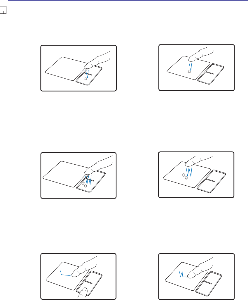
Double-clicking/Double-tapping - This is a common skill for launching a program directly from the
corresponding icon you select. Move the cursor over the icon you wish to execute, press the left button or
tap the pad twice in rapid succession, and the system launches the corresponding program. If the interval
between the clicks or taps is too long, the operation will not be executed. You can set the double-click speed
using the Windows Control Panel “Mouse.” The following 2 examples produce the same results.
Press the left button twice and
release.
Lightly but rapidly strike the
touchpad twice.
Press the left cursor button and
release.
Lightly but rapidly strike the
touchpad.
Clicking/Tapping -:LWKWKHFXUVRURYHUDQLWHPSUHVVWKHOHIWEXWWRQRUXVH\RXUÀQJHUWLSWRWRXFKWKH
WRXFKSDGOLJKWO\NHHSLQJ\RXUÀQJHURQWKHWRXFKSDGXQWLOWKHLWHPLVVHOHFWHG7KHVHOHFWHGLWHPZLOO
change color. The following 2 examples produce the same results.
Clicking Tapping
Double-
Clicking Double-
Tapping
Touchpad Usage Illustrations
Dragging -'UDJJLQJPHDQVWRSLFNXSDQLWHPDQGSODFHLWDQ\ZKHUHRQWKHVFUHHQ\RXZLVK<RXFDQ
move the cursor over the item you select, and while keeping the left button depressed, moving the cursor
to the desired location, then release the button. Or, you can simply double-tap on the item and hold while
GUDJJLQJWKHLWHPZLWK\RXUÀQJHUWLS7KHIROORZLQJLOOXVWUDWLRQVSURGXFHWKHVDPHUHVXOWV
+ROGOHIWEXWWRQDQGVOLGHÀQJHU
on touchpad.
Lightly strike the touchpad twice,
VOLGLQJÀQJHURQWRXFKSDGGXULQJ
second strike.
Dragging-
Clicking Dragging-
Tapping
38
4 Using the Notebook PC
NOTE: The touchpad responds to movement not to force. There is no need to tap
the surface too hard. Tapping too hard does not increase the responsiveness of the
touchpad. The touchpad responds best to light pressure.
Caring for the Touchpad
The touchpad is pressure sensitive. If not properly cared for, it can be easily damaged. Take note of the
following precautions.
• Make sure the touchpad does not come into contact with dirt, liquids or grease.
'RQRWWRXFKWKHWRXFKSDGLI\RXUÀQJHUVDUHGLUW\RUZHW
'RQRWUHVWKHDY\REMHFWVRQWKHWRXFKSDGRUWKHWRXFKSDGEXWWRQV
'RQRWVFUDWFKWKHWRXFKSDGZLWK\RXUÀQJHUQDLOVRUDQ\KDUGREMHFWV
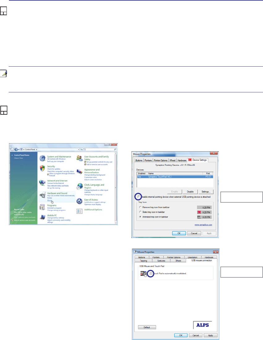
Automatic Touchpad Disabling (Synaptics)
Windows can automatically disable the Notebook PC’s touchpad when an external USB mouse is at-
tached. This feature is normally OFF, to turn ON this feature, select the option in Windows Control
Panel > Mouse Properties > Device Settings.
Select this option to
enable this feature.
Find Mouse properties in the “Control Panel”.
Models with Synaptics touchpad.
Models with ALPS touchpad.
Select this option to
enable this feature.
39
Using the Notebook PC 4
Storage Devices
6WRUDJHGHYLFHVDOORZWKH1RWHERRN3&WRUHDGRUZULWHGRFXPHQWVSLFWXUHVDQGRWKHUÀOHVWRYDULRXV
data storage devices. This Notebook PC has the following storage devices:
• Expansion Card
• Optical drive
• Flash memory reader
• Hard disk drive
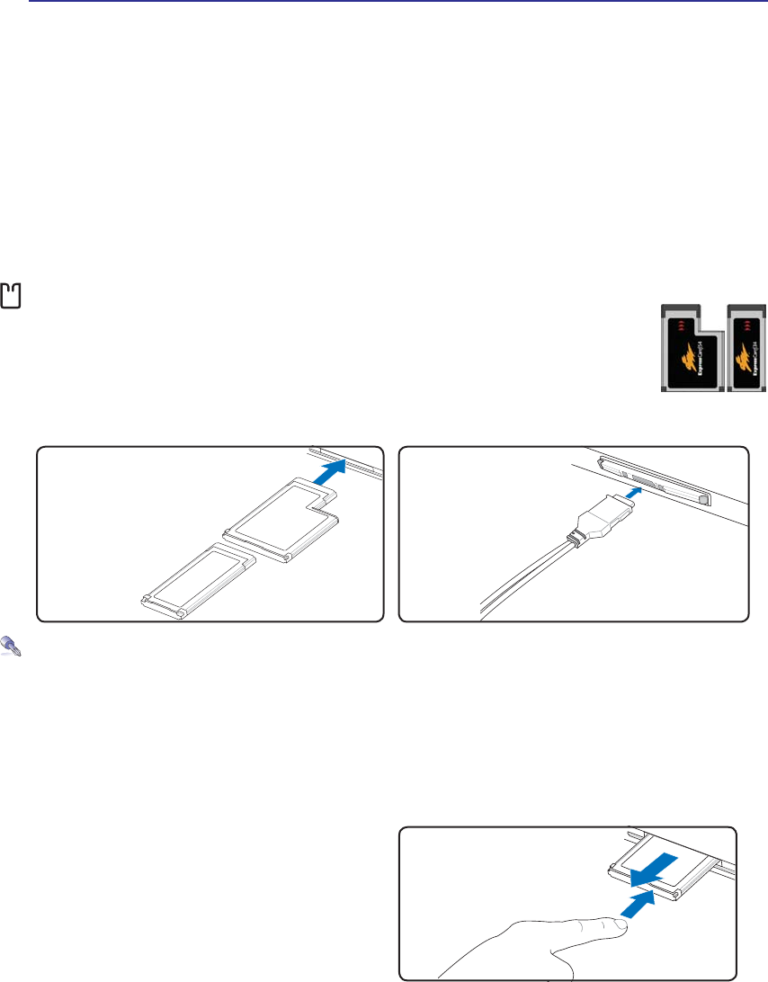
Expansion Card
One 26pin Express card slot is available to support one ExpressCard/34mm or one
ExpressCard/54mm expansion card. This new interface is faster by using a serial bus
supporting USB 2.0 and PCI Express instead of the slower parallel bus used in the PC
card slot. (Not compatible with previous PCMCIA cards.)
Inserting an Expansion Card
Be sure the ExpressCard
is level when inserting.
1. If there is an ExpressCard socket protector,
remove it using the “Removing an Express-
Card” instructions below.
2. Insert the ExpressCard with the connector side
ÀUVWDQGODEHOVLGHXS6WDQGDUG([SUHVV&DUGV
ZLOOEHÁXVKZLWKWKH1RWHERRN3&ZKHQIXOO\
inserted.
3. Carefully connect any cables or adapters
needed by the ExpressCard. Usually connectors
can only be inserted in one orientation. Look
for a sticker, icon, or marking on one side of
the connector representing the top side.
Removing an Expansion Card
The ExpressCard slot does not have an eject but-
ton. Press the ExpressCard inwards and release to
eject the ExpressCard. Carefully pull the ejected
ExpressCard out of the socket.
40
4 Using the Notebook PC
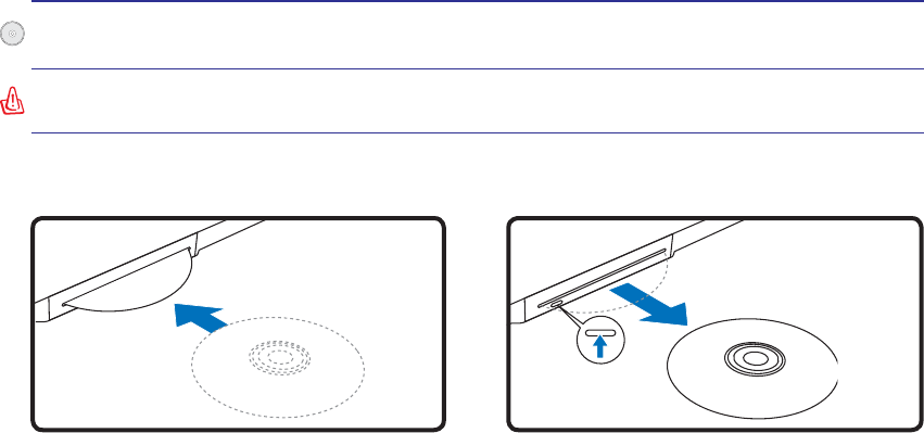
2. Gently grab the disc by the edges and pull
straight out.
1. While the Notebook PC’s power is ON, push
the electronic eject button (or use eject from
Windows operating system).
1. While the Notebook PC’s power is ON, insert
a disc slowly and the drive will receive the
disc and bring it in.
Inserting an optical disc Removing an optical disc
Optical Drive – slot type
Using the Optical Drive
$&'GULYHOHWWHUVKRXOGEHSUHVHQWUHJDUGOHVVRIWKHSUHVHQFHRID&'GLVFLQWKHGULYH$IWHUWKH&'LV
properly inserted, data can be accessed just like with hard disk drives; except that nothing can be written
WRRUFKDQJHGRQWKH&'8VLQJWKHSURSHUVRIWZDUHD&'5:GULYHRU'9'&'5:GULYHFDQDOORZ
&'5:GLVFVWREHXVHGOLNHDKDUGGULYHZLWKZULWLQJGHOHWLQJDQGHGLWLQJFDSDELOLWLHV
9LEUDWLRQLVQRUPDOIRUDOOKLJKVSHHGRSWLFDOGULYHVGXHWRXQEDODQFHG&'VRU&'SULQW7RGHFUHDVH
YLEUDWLRQXVHWKH1RWHERRN3&RQDQHYHQVXUIDFHDQGGRQRWSODFHODEHOVRQWKH&'
Listening to Audio CD
7KHRSWLFDOGULYHVFDQSOD\DXGLR&'VEXWRQO\WKH'9'520GULYHFDQSOD\'9'DXGLR,QVHUWWKH
DXGLR&'DQG:LQGRZVDXWRPDWLFDOO\RSHQVDQDXGLRSOD\HUDQGEHJLQVSOD\LQJ'HSHQGLQJRQWKH
'9'DXGLRGLVFDQGLQVWDOOHGVRIWZDUHLWPD\UHTXLUHWKDW\RXRSHQD'9'SOD\HUWROLVWHQWR'9'
DXGLR<RXFDQDGMXVWWKHYROXPHXVLQJKRWNH\VRU:LQGRZVVSHDNHULFRQRQWKHWDVNEDU
WARNING! The slot optical disc drive only supports a 16cm disc. The slot optical disc
drive does not support a 8cm disc. Inserting a 8cm disc may damage the slot drive.
41
Using the Notebook PC 4
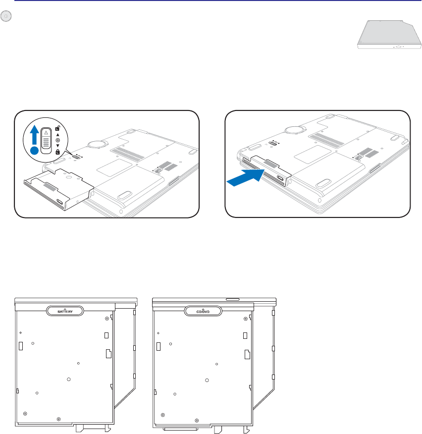
1
Inserting a module
Removing a module
Sample modules
Second battery pack Optical drive
Module Bay
This Notebook PC features a module bay to accept various modules such as optical
drives, travel drawer, or second battery pack. Visit an authorized dealer for upgrades.
42
4 Using the Notebook PC
IMPORTANT! Never remove cards while or immediately after reading, copying, format-
ting, or deleting data on the card or else data loss may occur.
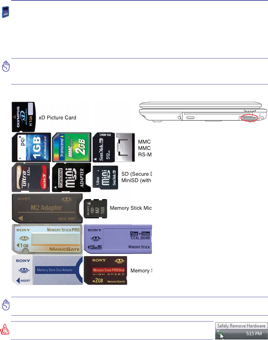
Memory Stick Duo/Pro/Duo Pro/MG (with MS adapater)
Memory Stick (MS)
Memory Stick Magic Gate (MG)
Memory Stick Select
SD (Secure Digital)
MiniSD (with SD adapter)
Memory Stick Micro (with MS adapter)
xD Picture Card
MMC (Multimedia Card)
MMC Plus
RS-MMC (Reduced Size) (with MMC adapter)
Flash Memory Card Reader
Normally a memory card reader must be purchased separately in order to use memory cards from devices
VXFKDVGLJLWDOFDPHUDV03SOD\HUVPRELOHSKRQHVDQG3'$V7KLV1RWHERRN3&KDVDVLQJOHEXLOWLQ
PHPRU\FDUGUHDGHUWKDWFDQXVHPDQ\ÁDVKPHPRU\FDUGVDVVKRZQLQWKHH[DPSOHEHORZ7KHEXLOWLQ
memory card reader is not only convenient, but also faster than most other forms of memory card readers
because it utilizes the internal high-bandwidth PCI bus.
IMPORTANT! Flash memory card compatibility varies depending on Notebook PC model
DQGÁDVKPHPRU\FDUGVSHFLÀFDWLRQV)ODVKPHPRU\FDUGVSHFLÀFDWLRQVFRQVWDQWO\
change so compatibility may change without warning.
Flash Memory Card Examples
WARNING! To prevent data loss, use “Windows Safely Remove Hard-
ZDUHµRQWKHWDVNEDUEHIRUHUHPRYLQJWKHÁDVKPHPRU\FDUG
43
Using the Notebook PC 4
9
76
1
4
2
3
5
10
8
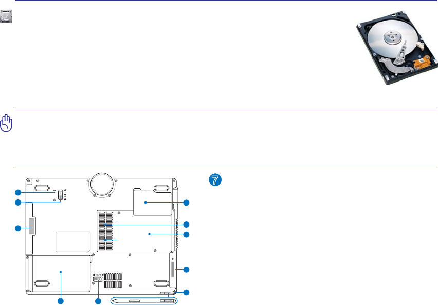
Hard Disk Drive Compartment
The hard disk drive is secured in a compartment. Visit
an authorized service center or retailer for informa-
tion on hard disk drive upgrades for your Notebook
PC. Only purchase hard disk drives from authorized
retailers of this Notebook PC to ensure maximum
compatibility and reliability.
7
Hard Disk Drive
+DUG GLVN GULYHV KDYH KLJKHU FDSDFLWLHV DQG RSHUDWH DW PXFK IDVWHU VSHHGV WKDQ
ÁRSS\GLVNGULYHVDQGRSWLFDOGULYHV7KH1RWHERRN3&FRPHVZLWKDUHSODFHDEOHKDUG
disk drive. Current hard drives support S.M.A.R.T. (Self Monitoring and Reporting
Technology) to detect hard disk errors or failures before they happen. When replacing
or upgrading the hard drive, always visit an authorized service center or retailer for this
Notebook PC.
IMPORTANT! Poor handling of the Notebook PC may damage the hard disk drive.
Handle the Notebook PC gently and keep it away from static electricity and strong
vibrations or impact. The hard disk drive is the most delicate component and will likely
EHWKHÀUVWRURQO\FRPSRQHQWWKDWLVGDPDJHGLIWKH1RWHERRN3&LVGURSSHG
44
4 Using the Notebook PC
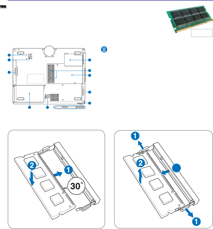
Installing a Memory Card: Removing a Memory Card:
9
76
1
4
2
3
5
10
8
3
2
The memory compartment provides expansion ca-
pabilities for additional memory. Visit an authorized
service center or retailer for information on memory
upgrades for your Notebook PC. Only purchase
expansion modules from authorized retailers of this
Notebook PC to ensure maximum compatibility and
reliability.
(This is only an example.) (This is only an example.)
Memory (RAM)
Additional memory will increase application performance by decreasing hard
disk access. The BIOS automatically detects the amount of memory in the system
DQGFRQÀJXUHV&026DFFRUGLQJO\GXULQJWKH32673RZHU2Q6HOI7HVWSURFHVV
There is no hardware or software (including BIOS) setup required after the memory
is installed.
This is only
an example.
45
Using the Notebook PC 4
NOTE: The built-in modem and network cannot be installed later as an upgrade. After
purchase, modem and/or network can be installed as an expansion card.
CAUTION: For electrical safety concerns, only use telephone cables rated 26AWG or
higher. (see Glossary for more information)
NOTE: When you are connected to an online service, do not place the Notebook PC
in suspend (or sleep mode) or else you will disconnect the modem connection.
Connections
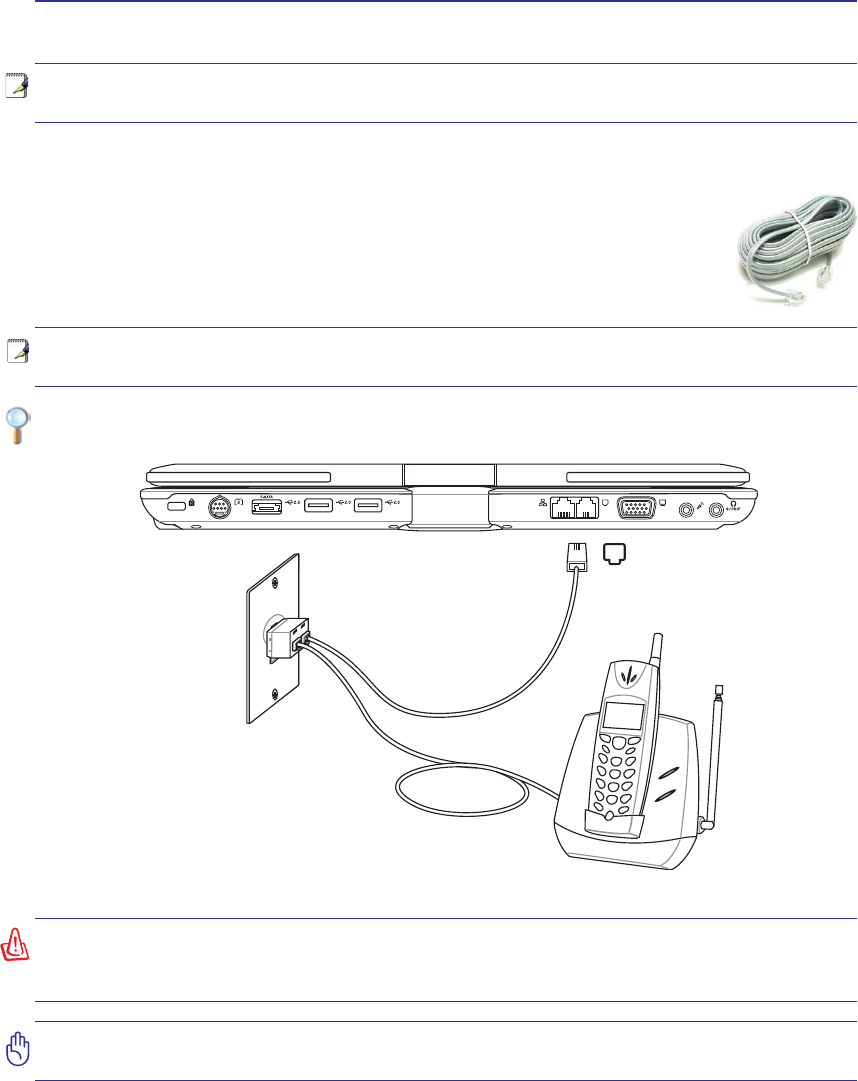
Example of the Notebook PC connected to a telephone jack for use with the built-in modem:
Modem Connection
The telephone wire used to connect the Notebook PC’s internal modem should have
either two or four wires (only two wires (telephone line #1) is used by the modem) and
should have an RJ-11 connector on both ends. Connect one end to the modem port and
the other end to an analog telephone wall socket (the ones found in residential buildings).
Once the driver is setup, the modem is ready to use.
Telephone Wall
Jack
Telephone cables
with RJ-11 connectors
Telephone
connection is
optional
Telephone connector
is the smaller of the two.
WARNING! Only use analog telephone outlets. The built-in modem does not support
the voltage used in digital phone systems. Do not connect the RJ-11 to digital phone
systems found in many commercial buildings or else damage will occur!
46
4 Using the Notebook PC
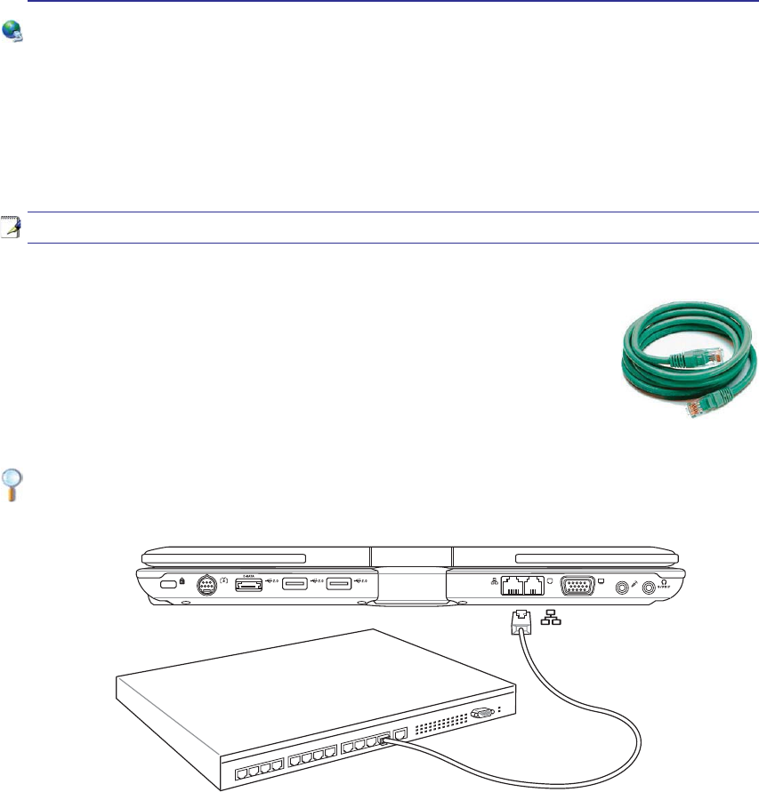
Example of the Notebook PC connected to a Network Hub or Switch for use with the built-in
Ethernet controller.
Network Connection
Connect a network cable, with RJ-45 connectors on each end, to the modem/network port on the Note-
book PC and the other end to a hub or switch. For 100 BASE-TX / 1000 BASE-T speeds, your network
cable must be category 5 or better (not category 3) with twisted-pair wiring. If you plan on running the
interface at 100/1000Mbps, it must be connected to a 100 BASE-TX / 1000 BASE-T hub (not a BASE-T4
KXE)RU%DVH7XVHFDWHJRU\RUWZLVWHGSDLUZLULQJ0ESV)XOO'XSOH[LVVXSSRUWHG
on this Notebook PC but requires connection to a network switching hub with “duplex” enabled. The
software default is to use the fastest setting so no user-intervention is required.
1000BASE-T (or Gigabit) is only supported on selected models.
Twisted-Pair Cable
7KHFDEOHXVHGWRFRQQHFWWKH(WKHUQHWFDUGWRDKRVWJHQHUDOO\D+XERU6ZLWFK
is called a straight-through Twisted Pair Ethernet (TPE). The end connectors are
called RJ-45 connectors, which are not compatible with RJ-11 telephone connectors.
If connecting two computers together without a hub in between, a crossover LAN
cable is required (Fast-Ethernet model). (Gigabit models support auto-crossover so
a crossover LAN cable is optional.)
Network Hub or Switch
Network cable with RJ-45 connectors
LAN
connector is the
larger of the two.
47
Using the Notebook PC 4
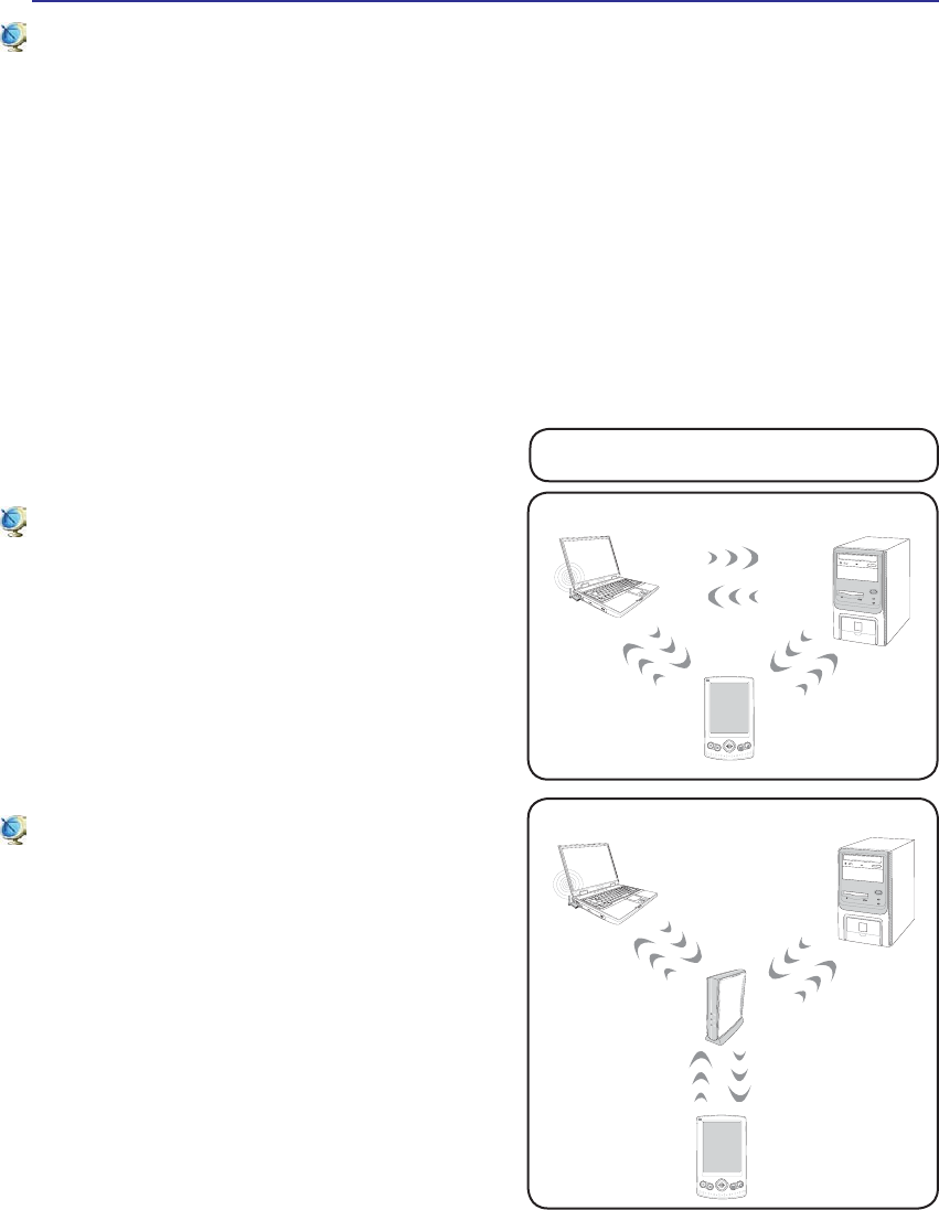
These are examples of the Notebook PC
connected to a Wireless Network.
Desktop PC
PDA
Notebook PC
Access
Point
Desktop PC
PDA
Notebook PC
Wireless LAN Connection (on selected models)
The optional built-in wireless LAN is a compact easy-to-use wireless Ethernet adapter. Implementing
the IEEE 802.11 standard for wireless LAN (WLAN), the optional built-in wireless LAN is capable of
IDVWGDWDWUDQVPLVVLRQUDWHVXVLQJ'LUHFW6HTXHQFH6SUHDG6SHFWUXP'666DQG2UWKRJRQDO)UHTXHQF\
'LYLVLRQ0XOWLSOH[LQJ2)'0WHFKQRORJLHVRQ*+]*+]IUHTXHQFLHV7KHRSWLRQDOEXLOWLQZLUH-
less LAN is backward compatible with the earlier IEEE 802.11 standards allowing seamless interfacing
of wireless LAN standards.
The optional built-in wireless LAN is a client adapter that supports Infrastructure and Ad-hoc modes
JLYLQJ\RXÁH[LELOLW\RQ\RXUH[LVWLQJRUIXWXUHZLUHOHVVQHWZRUNFRQÀJXUDWLRQVIRUGLVWDQFHVXSWR
meters between the client and the access point.
7RSURYLGHHIÀFLHQWVHFXULW\WR\RXUZLUHOHVVFRPPXQLFDWLRQWKHRSWLRQDOEXLOWLQZLUHOHVV/$1FRPHV
with a 64-bit/128-bit Wired Equivalent Privacy (WEP) encryption and Wi-Fi Protected Access (WPA)
features.
Ad-hoc mode
The Ad-hoc mode allows the Notebook PC to connect
to another wireless device. No access point (AP) is
required in this wireless environment.
(All devices must install optional 802.11 wireless LAN adapters.)
Infrastructure mode
The Infrastructure mode allows the Notebook PC and
other wireless devices to join a wireless network cre-
ated by an Access Point (AP) (sold separately) that
provides a central link for wireless clients to commu-
nicate with each other or with a wired network.
(All devices must install optional 802.11 wireless LAN adapters.)
48
4 Using the Notebook PC
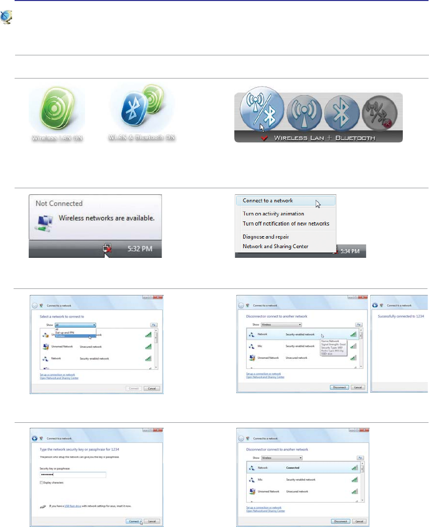
2. Press [FN F2] repeatedly until Wireless LAN
ON or WLAN & Bluetooth ON is shown.
Windows Wireless Network Connection
Connecting to a network
4. Right click on the network icon and select
Connect to a network.
3. You should see the “Not Connected” network
icon.
5. Select “Show Wireless” if you have many
networks in your area. 6. Select the wireless network you want to con-
nect to.
7. When connecting, you may have to enter a
password. 8. After connection has been established, “Con-
nected” will be shown.
2b. Or double click the Wireless Console icon on
the taskbar and select either the Wireless LAN
+ Bluetooth or just the Bluetooth.
1. Switch ON the Wireless function if necessary for your model (see switches in Section 3).
49
Using the Notebook PC 4
Bluetooth Wireless Connection (on selected models)
Notebook PCs with Bluetooth technology eliminates the need for cables for connecting
Bluetooth-enabled devices. Examples of Bluetooth-enabled devices may be Notebook PCs,
'HVNWRS3&VPRELOHSKRQHVDQG3'$V
Note: If your Notebook PC did not come with built-in Bluetooth, you need to connect
a USB or ExpressCard Bluetooth module in order to use Bluetooth.
Bluetooth-enabled mobile phones
<RXFDQZLUHOHVVFRQQHFWWR\RXUPRELOHSKRQH'HSHQGLQJRQ\RXUPRELOHSKRQH·VFDSD-
ELOLWLHV\RXFDQWUDQVIHUSKRQHERRNGDWDSKRWRVVRXQGÀOHVHWFRUXVHLWDVDPRGHPWR
connect to the Internet. You may also use it for SMS messaging.
Bluetooth-enabled computers or PDAs
<RXFDQZLUHOHVVFRQQHFWWRDQRWKHUFRPSXWHURU3'$DQGH[FKDQJHÀOHVVKDUHSHULSKHUDOVRU
share Internet or network connections. You may also make use of Bluetooth-enabled wireless
keyboard or mouse.
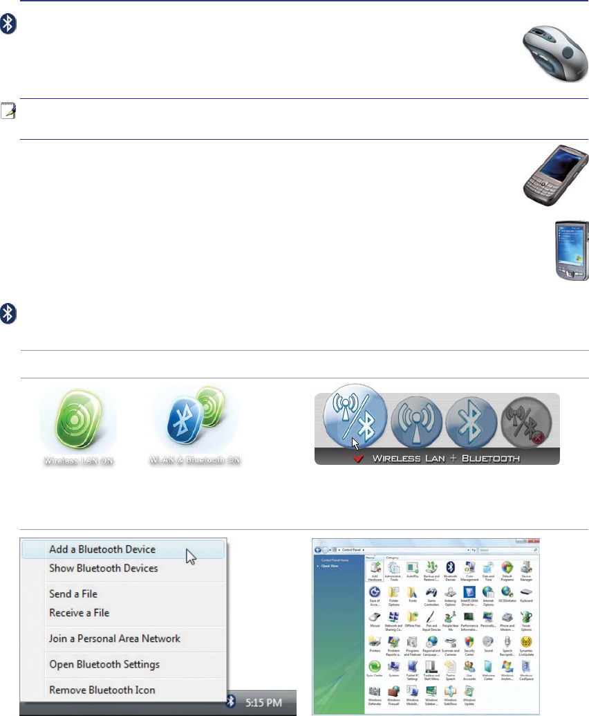
2b. Or double click the Wireless Console icon on
the taskbar and select either the Wireless LAN +
Bluetooth or just the Bluetooth.
3. Select Add a Bluetooth Device on the taskbar
men. 3b. Or Launch Bluetooth Devices from the Windows
Control Panel.
Turning ON and Launching Bluetooth Utility
This process can be used to add most Bluetooth devices. See Appendix for complete process.
2. Press [FN F2] repeatedly until Wireless LAN ON
or WLAN & Bluetooth ON is shown.
1. Switch ON the Wireless function if necessary for your model (see switches in Section 3).
50
4 Using the Notebook PC
Trusted Platform Module (TPM) (on selected models)
The TPM, or Trusted Platform Module, is a security hardware device on the system board that will hold
computer-generated keys for encryption. It is a hardware-based solution that an help avoid attacks by
hackers looking to capture passwords and encryption keys to sensitive data. The TPM provides the abil-
ity to the PC or notebook to run applications more secure and to make transactions and communication
more trustworthy.
The security features provided by the TPM are internally supported by the following cryptographic capa-
bilities of each TPM: hashing, random number generation, asymmetric key generation, and asymmetric
encryption/decryption. Each individual TPM on each individual computer system has a unique signature
initialized during the silicon manufacturing process that further enhances its trust/security effectiveness.
Each individual TPM must have an Owner before it is useful as a security device.
TPM Applications
TPM is useful for any customer that is interested in providing an addition layer of security to the com-
puter system. The TPM, when bundled with an optional security software package, can provide overall
V\VWHP VHFXULW\ ÀOH SURWHFWLRQ FDSDELOLWLHV DQG SURWHFW DJDLQVW HPDLOSULYDF\ FRQFHUQV 730 KHOSV
provide security that can be stronger than that contained in the system BIOS, operating system, or any
non-TPM application.
Important: Use your TPM application’s
“Restore” or “Migration” function to
backup your TPM security data.
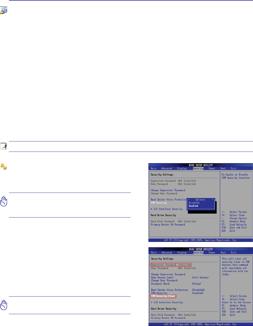
Note: The TPM is disabled by default. Use BIOS setup to enable it.
Enabling TPM Security
Enter BIOS SetupSUHVV>)@RQV\VWHPVWDUWXS
On Security page, set TPM Security to [Enabled]
Clearing TPM Secured Data
When Supervisor Password is installed, TPM
Security Clear will appear. Use this item to clear
all data secured by TPM. (You have to restart the
Notebook PC after setting the password to see the
security clear option.)
Important: Use should routinely backup
your TPM secured data.
51
Using the Notebook PC 4
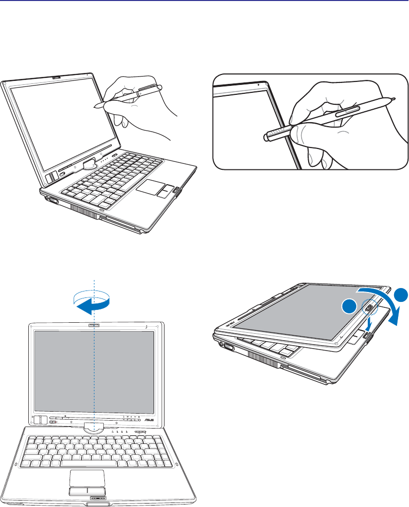
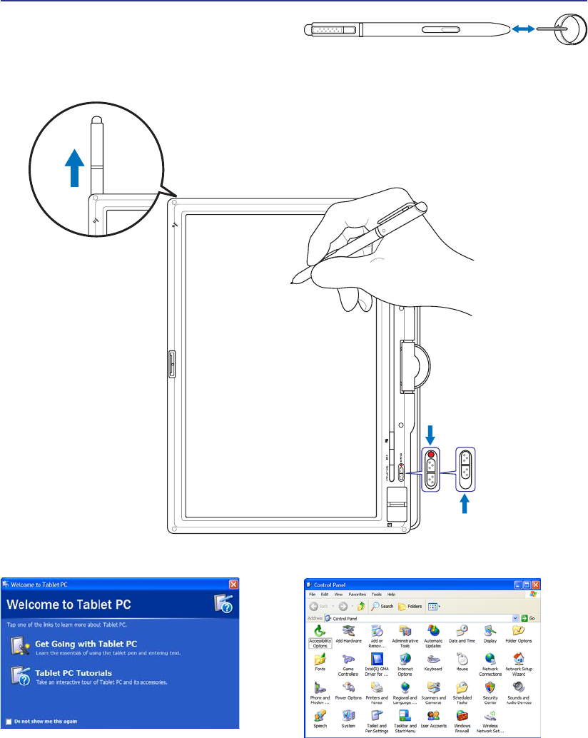
Tablet PC Mode
The following are illustrations for using the tablet PC function.
Use the tip of the tablet PC pen to activate the writing
function.
Use the back of the tablet PC pen to activate the erasing
function.
Rotate the display panel vertically using both hands to
support the sides of the display panel from rocking.
When the display is rotated into the tablet PC mode, the
latch must be reversed in order to lock the display panel.
POWER
ON OFF
HOLD
ESC
CTRL.ALT.DEL
1
2
52
4 Using the Notebook PC
Tablet PC Mode (Cont.)
Windows “Control Panel” also provide “Tablet and
Pen Settings” to customize software settings for
Tablet PC use.
Information will be available to help you use the
Notebook PC in Tablet PC mode when you enter
Windows.
Over long-term use, the plastic tip on the touchscreen pen
needs replacing when it wears close to the pen. Use the
provided tool to remove and insert a new tip (also provided)
before the tip wears out.
Press this latch down to
lock the display panel.
Enable
keys.
Disable
keys.
Use the HOLD switch
to disable the keys on
the display panel from
accidental activation.
Keep this side with air vents
away from your body.

Appendix
Optional Accessories & Connections
Operating System and Software
Declarations and Safety Statements
Notebook PC Information
NOTE: Photos and icons in this manual are used for artistic purposes only and do not
show what is actually used in the product itself.
A Appendix
Optional Accessories
These items, if desired, come as optional items to complement your Notebook PC.
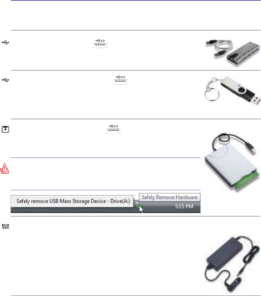
USB Flash Memory Disk
$86%ÁDVKPHPRU\GLVNLVDQRSWLRQDOLWHPWKDWFDQUHSODFHWKH0%ÁRSS\
disk and provide storage up to several hundred megabytes, higher transfer speeds,
and greater durability. When used in current operating systems, no drivers are
necessary.
USB Hub (Optional)
Attaching an optional USB hub will increase your USB ports and allow you to
quickly connect or disconnect many USB peripherals through a single cable.
Vehicle Power Adapter
The vehicle power adapter provides a source of power for using the Notebook
PC and/or charging the Notebook PC’s battery pack while in transit when no AC
power is available. This product is an essential tool for today’s mobile profes-
sional. Your purchase will enhance the power, performance, and versatility of
your portable computer while traveling on the road or on the sea. The Vehicle
Power Adapter can be used in vehicles or boats using a standard cigarette lighter
VRFNHW 7KH9HKLFOH 3RZHU$GDSWHU DFFHSWV LQSXW UDQJHV IURP 9'& WR
9'&9ROWV'LUHFW&XUUHQW
USB Floppy Disk Drive
$QRSWLRQDO86%LQWHUIDFHÁRSS\GLVNGULYHFDQDFFHSWDVWDQGDUG0%RU
.%LQFKÁRSS\GLVNHWWH
WARNING! To prevent system failures, use Windows “Safely
Remove Hardware” on the taskbar before disconnecting the USB
ÁRSS\GLVNGULYH(MHFWWKHÁRSS\GLVNEHIRUHWUDQVSRUWLQJWKH
Notebook PC to prevent damage from shock.
Appendix A
Optional Connections
These items, if desired, may be purchased from third-parties.
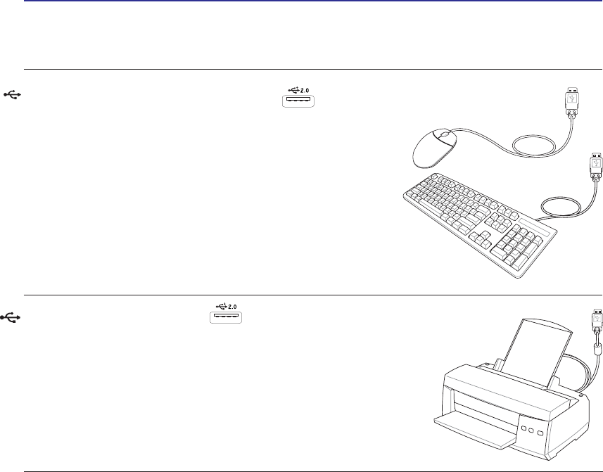
USB Keyboard and Mouse
Attaching an external USB keyboard will allow data entry to be
more comfortable. Attaching an external USB mouse will allow
Windows navigation to be more comfortable. Both the external
USB keyboard and mouse will work simultaneously with the
Notebook PC’s built-in keyboard and touchpad.
Printer Connection
One or more USB printers can be simultaneously used on any USB port
or USB hub.
A Appendix
R
E
S
E
T
OFF ON
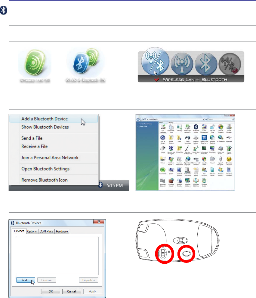
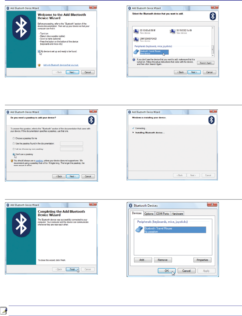
4. Prepare the Bluetooth mouse.
• Install two “AA” batteries.
• Turn ON the power switch on the bottom of the
mouse. The bottom sensor should glow red.
• Push the “RESET” button on the bottom of the
Bluetooth mouse.
Bluetooth Mouse Setup (optional)
This process can be used to add most Bluetooth devices in Windows operating system.
3. Select Add a Bluetooth Device on
the taskbar menu.
3c. If launched from the Control Panel,
click Add from this screen.
3b. Or Launch Bluetooth Devices from the
Windows Control Panel.
2b. Or double click the Wireless Console icon on
the taskbar and select either the Wireless LAN +
Bluetooth or just the Bluetooth.
2. Press [FN F2] repeatedly until Wireless LAN ON
or WLAN & Bluetooth ON is shown.
1. Switch ON the Wireless function if necessary for your model (see switches in Section 3).
Appendix A
Note: “RESET” may be necessary after changing batteries. Repeat steps if necessary.
5. Click Next when the Bluetooth mouse
is ready. 6. A list of nearby Bluetooth devices will
be shown. Select the Bluetooth mouse
and click Next.
7. Select “Don’t use a passkey” and click
Next.
9. Click Finish when adding is complete. 10. You will see your device in the window.
You can also add or remove Bluetooth
devices here.
8. Wait while the Bluetooth mouse is being
added.

A Appendix
Support Software
This Notebook PC comes with a support disc that provides BIOS, drivers and applications
to enable hardware features, extend functionality, help manage your Notebook PC, or
add functionality not provided by the native operating system. If updates or replace-
ment of the support disc is necessary, contact your dealer for web sites to download
individual software drivers and utilities.
The support disc contains all drivers, utilities and software for all popular operating systems
including those that have been pre-installed. The support disc does not include the operating system
LWVHOI7KHVXSSRUWGLVFLVQHFHVVDU\HYHQLI\RXU1RWHERRN3&FDPHSUHFRQÀJXUHGLQRUGHUWRSURYLGH
additional software not included as part of the factory pre-install.
A recovery disc is optional and includes an image of the original operating system installed on the hard
drive at the factory. The recovery disc provides a comprehensive recovery solution that quickly restores
the Notebook PC’s operating system to its original working state provided that your hard disk drive is
in good working order. Contact your retailer if you require such a solution.
Note: Some of the Notebook PC’s components and features may not work until the
device drivers and utilities are installed.
Operating System and Software
This Notebook PC may offer (depending on territory) its customers the choice of a pre-installed Micro-
soft Windows operating system. The choices and languages will depend on the territory. The levels of
hardware and software support may vary depending on the installed operating system. The stability and
compatibility of other operating systems cannot be guaranteed.

Appendix A
Federal Communications Commission Statement
This device complies with FCC Rules Part 15. Operation is subject to the following two conditions:
• This device may not cause harmful interference, and
• This device must accept any interference received, including interference that may cause undesired
operation.
This equipment has been tested and found to comply with the limits for a class B digital device, pursuant
to Part 15 of the Federal Communications Commission (FCC) rules. These limits are designed to provide
reasonable protection against harmful interference in a residential installation. This equipment generates,
uses, and can radiate radio frequency energy and, if not installed and used in accordance with the instructions,
PD\FDXVHKDUPIXOLQWHUIHUHQFHWRUDGLRFRPPXQLFDWLRQV+RZHYHUWKHUHLVQRJXDUDQWHHWKDWLQWHUIHUHQFH
will not occur in a particular installation. If this equipment does cause harmful interference to radio or
television reception, which can be determined by turning the equipment off and on, the user is encouraged
to try to correct the interference by one or more of the following measures:
• Reorient or relocate the receiving antenna.
• Increase the separation between the equipment and receiver.
• Connect the equipment into an outlet on a circuit different from that to which the receiver is
connected.
• Consult the dealer or an experienced radio/TV technician for help.
WARNING! The use of a shielded-type power cord is required in order to meet FCC
emission limits and to prevent interference to the nearby radio and television recep-
tion. It is essential that only the supplied power cord be used. Use only shielded
cables to connect I/O devices to this equipment. You are cautioned that changes or
PRGLÀFDWLRQVQRWH[SUHVVO\DSSURYHGE\WKHSDUW\UHVSRQVLEOHIRUFRPSOLDQFHFRXOG
void your authority to operate the equipment.
5HSULQWHGIURPWKH&RGHRI)HGHUDO5HJXODWLRQVSDUW:DVKLQJWRQ'&2IÀFHRIWKH)HGHUDO
5HJLVWHU1DWLRQDO$UFKLYHVDQG5HFRUGV$GPLQLVWUDWLRQ86*RYHUQPHQW3ULQWLQJ2IÀFH
CE Mark Warning
This is a Class B product, in a domestic environment, this product may cause radio interference, in which
case the user may be required to take adequate measures.

A Appendix
R&TTE Directive (1999/5/EC)
7KHIROORZLQJLWHPVZHUHFRPSOHWHGDQGDUHFRQVLGHUHGUHOHYDQWDQGVXIÀFLHQWIRUWKH577(5DGLR
& Telecommunications Terminal Equipment) directive:
(VVHQWLDOUHTXLUHPHQWVDVLQ>$UWLFOH@
3URWHFWLRQUHTXLUHPHQWVIRUKHDOWKDQGVDIHW\DVLQ>$UWLFOHD@
7HVWLQJIRUHOHFWULFVDIHW\DFFRUGLQJWR>(1@
3URWHFWLRQUHTXLUHPHQWVIRUHOHFWURPDJQHWLFFRPSDWLELOLW\LQ>$UWLFOHE@
7HVWLQJIRUHOHFWURPDJQHWLFFRPSDWLELOLW\LQ>(1@>(1@
7HVWLQJDFFRUGLQJWR>@
(IIHFWLYHXVHRIWKHUDGLRVSHFWUXPDVLQ>$UWLFOH@
5DGLRWHVWVXLWHVDFFRUGLQJWR>(1@
FCC Radio Frequency Interference Requirements
7KLVGHYLFHLVUHVWULFWHGWR,1'22586(GXHWRLWVRSHUDWLRQLQWKHWR*+]IUHTXHQF\UDQJH
)&&UHTXLUHVWKLVSURGXFWWREHXVHGLQGRRUVIRUWKHIUHTXHQF\UDQJHWR*+]WRUHGXFHWKH
potential for harmful interference to co-channel of the Mobile Satellite Systems.
+LJKSRZHUUDGDUVDUHDOORFDWHGDVSULPDU\XVHURIWKHWR*+]DQGWR*+]EDQGV
These radar stations can cause interference with and / or damage this device.
IMPORTANT: This device and its antenna(s) must not be co-located or operating in
conjunction with any other antenna or transmitter.
FCC Radio Frequency (RF) Exposure Caution Statement
This equipment complies with FCC RF exposure limits set forth for an uncontrolled environment. To
maintain compliance with FCC RF exposure compliance requirements, please follow operation instruc-
WLRQVLQWKHXVHU·VPDQXDO7KLVHTXLSPHQWLVIRURSHUDWLRQZLWKLQ*+]DQG*+]IUHTXHQF\
ranges and is restricted to indoor environments only.
)&&&DXWLRQ$Q\FKDQJHVRUPRGLÀFDWLRQVQRWH[SUHVVO\DSSURYHGE\WKHSDUW\UH-
sponsible for compliance could void the user’s authority to operate this equipment.
“The manufacturer declares that this device is limited to Channels 1 through 11 in the
*+]IUHTXHQF\E\VSHFLÀHGÀUPZDUHFRQWUROOHGLQWKH86$µ

Appendix A
France Restricted Wireless Frequency Bands
Some areas of France have a restricted frequency band. The worst case maximum authorized power
indoors are:
P:IRUWKHHQWLUH*+]EDQG0+]²0+]
P:IRUIUHTXHQFLHVEHWZHHQ0+]DQG0+]
NOTE: Channels 10 through 13 inclusive operate in the band 2446.6 MHz to 2483.5 MHz.
There are few possibilities for outdoor use: On private property or on the private property of public
SHUVRQVXVHLVVXEMHFWWRDSUHOLPLQDU\DXWKRUL]DWLRQSURFHGXUHE\WKH0LQLVWU\RI'HIHQVHZLWKPD[L-
PXPDXWKRUL]HGSRZHURIP:LQWKH²0+]EDQG8VHRXWGRRUVRQSXEOLFSURSHUW\
is not permitted.
,QWKHGHSDUWPHQWVOLVWHGEHORZIRUWKHHQWLUH*+]EDQG
• Maximum authorized power indoors is 100mW
• Maximum authorized power outdoors is 10mW
'HSDUWPHQWVLQZKLFKWKHXVHRIWKH²0+]EDQGLVSHUPLWWHGZLWKDQ(,53RIOHVVWKDQ
100mW indoors and less than 10mW outdoors:
$LQ2ULHQWDOHV $LVQH $OOLHU +DXWHV$OSHV
08 Ardennes 09 Ariège 11 Aude 12 Aveyron
&KDUHQWH 'RUGRJQH 'RXEV 'U{PH
32 Gers 36 Indre 37
Indre et Loire
41 Loir et Cher
45 Loiret 50 Manche 55 Meuse 58 Nièvre
1RUG 2LVH 2UQH 3X\GX'{PH
64
Pyrénées Atlantique
3\UpQpHV %DV5KLQ +DXW5KLQ
+DXWH6D{QH
6D{QHHW/RLUH
75 Paris 82 Tarn et Garonne
84 Vaucluse 88 Vosges 89 Yonne 90
Territoire de Belfort
94 Val de Marne
This requirement is likely to change over time, allowing you to use your wireless LAN card in more
areas within France. Please check with ART for the latest information (www.art-telecom.fr)
NOTE: Your WLAN Card transmits less than 100mW, but more than 10mW.
Wireless Operation Channel for Different Domains
1$PHULFD *+] &KWKURXJK&+
-DSDQ *+] &KWKURXJK&K
(XURSH(76, *+] &KWKURXJK&K

A Appendix
UL Safety Notices
Required for UL 1459 covering telecommunications (telephone) equipment intended to be electrically
connected to a telecommunication network that has an operating voltage to ground that does not exceed
200V peak, 300V peak-to-peak, and 105V rms, and installed or used in accordance with the National
Electrical Code (NFPA 70).
When using the Notebook PC modem, basic safety precautions should always be followed to reduce the
ULVNRIÀUHHOHFWULFVKRFNDQGLQMXU\WRSHUVRQVLQFOXGLQJWKHIROORZLQJ
•Do not use the Notebook PC near water, for example, near a bath tub, wash bowl, kitchen sink
or laundry tub, in a wet basement or near a swimming pool.
• Do not use the Notebook PC during an electrical storm. There may be a remote risk of electric
shock from lightning.
•Do not use the Notebook PC in the vicinity of a gas leak.
Required for UL 1642 covering primary (non-rechargeable) and secondary (rechargeable) lithium batter-
ies for use as power sources in products. These batteries contain metallic lithium, or a lithium alloy, or
a lithium ion, and may consist of a single electrochemical cell or two or more cells connected in series,
parallel, or both, that convert chemical energy into electrical energy by an irreversible or reversible
chemical reaction.
•Do not GLVSRVHWKH1RWHERRN3&EDWWHU\SDFNLQDÀUHDVWKH\PD\H[SORGH&KHFNZLWKORFDO
codes for possible special disposal instructions to reduce the risk of injury to persons due to
ÀUHRUH[SORVLRQ
•Do not use power adapters or batteries from other devices to reduce the risk of injury to per-
VRQVGXHWRÀUHRUH[SORVLRQ8VHRQO\8/FHUWLÀHGSRZHUDGDSWHUVRUEDWWHULHVVXSSOLHGE\WKH
manufacturer or authorized retailers.
Power Safety Requirement
Products with electrical current ratings up to 6A and weighing more than 3Kg must use approved power
FRUGVJUHDWHUWKDQRUHTXDOWR+99)*PP2RU+99)*PP2.

Appendix A
Nordic Lithium Cautions (for lithium-ion batteries)
(Japanese)
CAUTION! 'DQJHURIH[SORVLRQLIEDWWHU\LVLQFRUUHFWO\UHSODFHG5HSODFHRQO\ZLWK
WKHVDPHRUHTXLYDOHQWW\SHUHFRPPHQGHGE\WKHPDQXIDFWXUHU'LVSRVHRIXVHGEDW-
teries according to the manufacturer’s instructions. (English)
ATTENZIONE! Rischio di esplosione della batteria se sostituita in modo errato. Sosti-
tuire la batteria con un una di tipo uguale o equivalente consigliata dalla fabbrica. Non
disperdere le batterie nell’ambiente. (Italian)
VORSICHT! Explosionsgetahr bei unsachgemäßen Austausch der Batterie. Ersatz nur
GXUFKGHQVHOEHQRGHUHLQHPYRP+HUVWHOOHUHPSIRKOHQHPlKQOLFKHQ7\S(QWVRUJXQJ
JHEUDXFKWHU%DWWHULHQQDFK$QJDEHQGHV+HUVWHOOHUV*HUPDQ
ADVARSELI! Lithiumbatteri - Eksplosionsfare ved fejlagtig håndtering. Udskiftning
må kun ske med batteri af samme fabrikat og type. Levér det brugte batteri tilbage til
OHYHUDQG¡UHQ'DQLVK
VARNING! Explosionsfara vid felaktigt batteribyte. Använd samma batterityp eller en
ekvivalent typ som rekommenderas av apparattillverkaren. Kassera använt batteri enligt
fabrikantens instruktion. (Swedish)
VAROITUS! Paristo voi räjähtää, jos se on virheellisesti asennettu. Vaihda paristo aino-
DVWDDQODLWHYDOPLVWDMDQVRXVLWWHOHPDDQW\\SSLLQ+lYLWlNl\WHWW\SDULVWRYDOPLVWDJDQRKMHLGHQ
mukaisesti. (Finnish)
ATTENTION! Il y a danger d’explosion s’il y a remplacement incorrect de la bat-
terie. Remplacer uniquement avec une batterie du mêre type ou d’un type équivalent
recommandé par le constructeur. Mettre au rebut les batteries usagées conformément
aux instructions du fabricant. (French)
ADVARSEL! Eksplosjonsfare ved feilaktig skifte av batteri. Benytt samme batteritype
eller en tilsvarende type anbefalt av apparatfabrikanten. Brukte batterier kasseres i
henhold til fabrikantens instruksjoner. (Norwegian)

A Appendix
CTR 21 Approval (for Notebook PC with built-in Modem)
Danish
Dutch
English
Finnish
French
German
Greek
Italian
Portuguese
Spanish
Swedish

Appendix A

A Appendix
Notebook PC Information
This page is provided for recording information concerning your Notebook PC for future reference or
IRUWHFKQLFDOVXSSRUW.HHSWKLV8VHU·V0DQXDOLQDVHFXUHGORFDWLRQLISDVVZRUGVDUHÀOOHGRXW
Owner’s Name: ___________________________ Owner’s Telephone: ______________
Manufacturer:_______________ Model: ___________ Serial Number: ______________
Display Size: ___________ Resolution: _____________Memory Size: ______________
Retailer: _________________Location: ___________ Purchase Date: ______________
Hard Drive Manufacturer: ____________________________ Capacity: ______________
Optical Drive Manufacturer: _____________________________ Type: ______________
BIOS Version:__________________________________________Date: ______________
Accessories: _____________________________________________________________
Accessories: _____________________________________________________________
Software
Operating System:__________Version: ___________ Serial Number: ______________
Software: _________________Version: ___________ Serial Number: ______________
Software: _________________Version: ___________ Serial Number: ______________
Security
Supervisor Name: _______________________ Supervisor Password: ______________
User Name:___________________________________User Password: ______________
Network
User Name:______________Password: _________________ Domain: ______________
User Name:______________Password: _________________ Domain: ______________
Copyright Information
No part of this manual, including the products and software described in it, may be reproduced, trans-
mitted, transcribed, stored in a retrieval system, or translated into any language in any form or by any
means, except documentation kept by the purchaser for backup purposes, without the express written
permission of ASUSTeK COMPUTER INC. (“ASUS”).
$686 3529,'(6 7+,6 0$18$/ ´$6 ,6µ :,7+287 :$55$17< 2)$1< .,1' (,7+(5
(;35(6625,03/,(',1&/8',1*%87127/,0,7('727+(,03/,(':$55$17,(625
&21',7,2162)0(5&+$17$%,/,7<25),71(66)25$3$57,&8/$5385326(,112
(9(17 6+$//$686 ,76 ',5(&7256 2)),&(56 (03/2<((6 25$*(176 %( /,$%/(
)25$1<,1',5(&763(&,$/,1&,'(17$/25&216(48(17,$/'$0$*(6,1&/8',1*
'$0$*(6)25/2662)352),76/2662) %86,1(66/2662)86(25 '$7$,17(5-
5837,212)%86,1(66$1'7+(/,.((9(1,)$686+$6%((1$'9,6('2)7+(326-
6,%,/,7<2)68&+'$0$*(6$5,6,1*)520$1<'()(&725(5525,17+,60$18$/
25352'8&7
Products and corporate names appearing in this manual may or may not be registered trademarks or
FRS\ULJKWVRIWKHLUUHVSHFWLYHFRPSDQLHVDQGDUHXVHGRQO\IRULGHQWLÀFDWLRQRUH[SODQDWLRQDQGWRWKH
RZQHUV·EHQHÀWZLWKRXWLQWHQWWRLQIULQJH
63(&,),&$7,216$1',1)250$7,21&217$,1(',17+,60$18$/$5()851,6+(')25
,1)250$7,21$/86(21/<$1'$5(68%-(&772&+$1*($7$1<7,0(:,7+28712-
7,&($1'6+28/'127%(&216758('$6$&200,70(17%<$686$686$6680(612
5(63216,%,/,7<25/,$%,/,7<)25$1<(5525625,1$&&85$&,(67+$70$<$33($5
,17+,60$18$/,1&/8',1*7+(352'8&76$1'62)7:$5('(6&5,%(',1,7
Copyright © 2007 ASUSTeK COMPUTER INC. All Rights Reserved.
Limitation of Liability
Circumstances may arise where because of a default on ASUS’ part or other liability, you are entitled to
recover damages from ASUS. In each such instance, regardless of the basis on which you are entitled
to claim damages from ASUS, ASUS is liable for no more than damages for bodily injury (including
death) and damage to real property and tangible personal property; or any other actual and direct dam-
ages resulted from omission or failure of performing legal duties under this Warranty Statement, up to
the listed contract price of each product.
ASUS will only be responsible for or indemnify you for loss, damages or claims based in contract, tort
or infringement under this Warranty Statement.
This limit also applies to ASUS’ suppliers and its reseller. It is the maximum for which ASUS, its sup-
pliers, and your reseller are collectively responsible.
81'(512&,5&8067$1&(6,6$686/,$%/()25$1<2)7+()2//2:,1*7+,5'
3$57<&/$,06$*$,167<28)25'$0$*(6/2662)25'$0$*(72<2855(-
&25'625'$7$2563(&,$/,1&,'(17$/25,1',5(&7'$0$*(625)25$1<
(&2120,&&216(48(17,$/'$0$*(6,1&/8',1*/267352),76256$9,1*6(9(1
,)$686,766833/,(5625<2855(6(//(5,6,1)250('2)7+(,53266,%,/,7<
Service and Support
Visit our multi-language web site at http://support.asus.com