ASUSTeK Computer R1F Notebook PC User Manual 2
ASUSTeK Computer Inc Notebook PC 2
Contents
User Manual 2
41
Using the Notebook PC 4
MS (Memory Stick)
Duo/Pro/Duo Pro/MG
MS (Memory Stick)
Select
MS (Memory Stick)
Magic Gate (MG)
MS (Memory Stick)
MS adapter
MMC (Multimedia Card)
SD (Secure Digital)
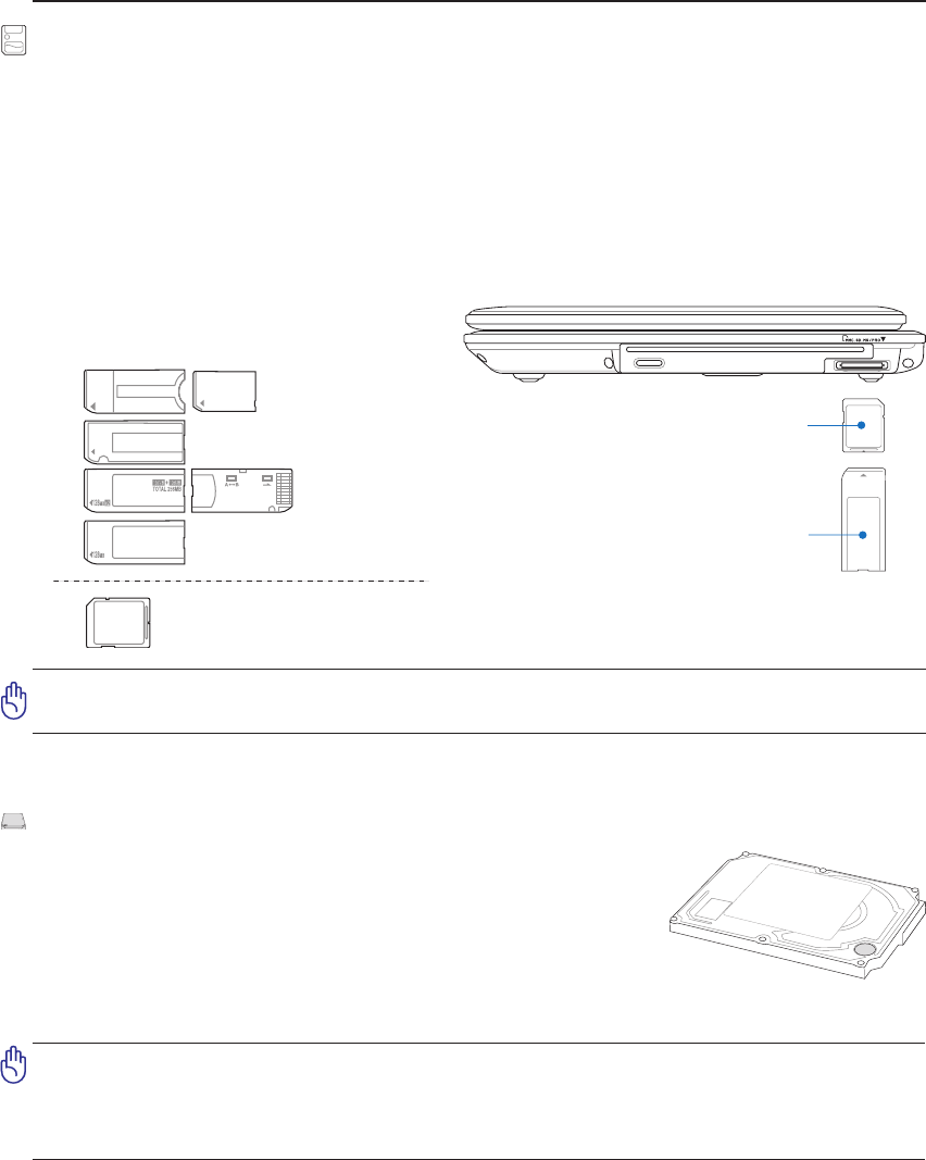
Supported Memory Types
IMPORTANT! Never remove cards while or immediately after reading, copying, format-
ting, or deleting data on the card or else data loss may occur.
SD / MMC
MS / MS Pro
512MB
Flash Memory Card Reader
Normally a PCMCIA memory card reader must be purchased separately in order to use memory cards
from devices such as digital cameras, MP3 players, mobile phones, and PDAs. This Notebook PC has
a single built-in memory card reader that can read the following ash memory cards: Secure Digital
(SD), Multi-Media Card (MMC), Memory Stick (MS), Memory Stick Select (MS Select), Memory
Stick Duo (with MS adapter), Memory Stick Pro, and Memory Stick Pro Duo (with MS Pro adapter).
Memory Sticks may be standard or with MagicGate technology. The built-in memory card reader is not
only convenient, but also faster than most other forms of memory card readers because it utilizes the
high-bandwidth PCI bus.
Hard Disk Drive
Hard disk drives have higher capacities and operate at much faster speeds
than oppy disk drives and optical drives. The Notebook PC comes with
a replaceable 2.5” (6.35cm) wide and approximately .374” (.95cm) high
hard disk drive. Current hard drives support S.M.A.R.T. (Self Monitoring
and Reporting Technology) to detect hard disk errors or failures before
they happen. When replacing or upgrading the hard drive, always visit
an authorized service center or retailer for this Notebook PC.
IMPORTANT! Poor handling of the Notebook PC may damage the hard disk drive.
Handle the Notebook PC gently and keep it away from static electricity and strong
vibrations or impact. The hard disk drive is the most delicate component and will
likely be the rst or only component that is damaged if the Notebook PC is dropped.
42
4 Using the Notebook PC
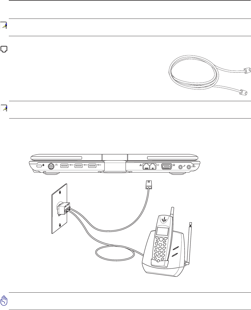
Telephone Wall
Jack
Telephone cables
with RJ-11 connectors
Telephone
connection is
optional
Telephone connector is the
smaller of the two.
NOTE: The built-in modem and network cannot be installed later as an upgrade. After
purchase, modem and/or network can be installed as a PC card (PCMCIA).
CAUTION: For electrical safety concerns, only use telephone cables rated 26AWG or
higher. (see Glossary for more information)
NOTE: When you are connected to an online service, do not place the Notebook PC in
suspend (or sleep mode) or else you will disconnect the modem connection.
Example of the Notebook PC connected to a telephone jack for use with the built-in modem:
Connections
Modem Connection
The telephone wire used to connect the Notebook PC’s internal mo-
dem should have either two or four wires (only two wires (telephone
line #1) is used by the modem) and should have an RJ-11 connector
on both ends. Connect one end to the modem port and the other end
to an analog telephone wall socket (the ones found in residential
buildings). Once the driver is setup, the modem is ready to use.
43
Using the Notebook PC 4
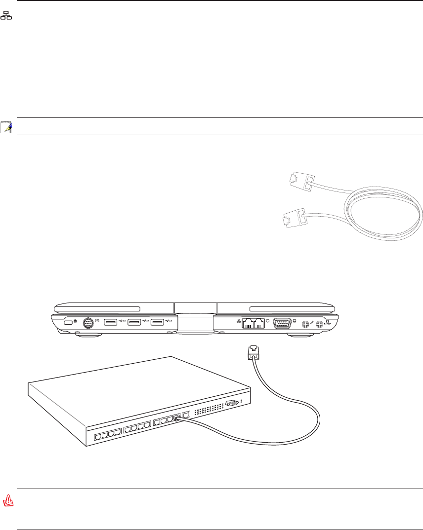
Network Hub or Switch
Network cable with RJ-45 connectors
LAN connector is the
larger of the two.
Example of the Notebook PC connected to a Network Hub or Switch for use with the built-in
Ethernet controller.
WARNING! Only use analog telephone outlets. The built-in modem does not support
the voltage used in digital phone systems. Do not connect the RJ-11 to digital phone
systems found in many commercial buildings or else damage will occur!
Network Connection
Connect a network cable, with RJ-45 connectors on each end, to the modem/network port on the Note-
book PC and the other end to a hub or switch. For 100 BASE-TX / 1000 BASE-T speeds, your network
cable must be category 5 or better (not category 3) with twisted-pair wiring. If you plan on running the
interface at 100/1000Mbps, it must be connected to a 100 BASE-TX / 1000 BASE-T hub (not a BASE-T4
hub). For 10Base-T, use category 3, 4, or 5 twisted-pair wiring. 10/100 Mbps Full-Duplex is supported
on this Notebook PC but requires connection to a network switching hub with “duplex” enabled. The
software default is to use the fastest setting so no user-intervention is required.
1000BASE-T (or Gigabit) is only supported on selected models.
Twisted-Pair Cable
The cable used to connect the Ethernet card to a host (generally a
Hub or Switch) is called a straight-through Twisted Pair Ethernet
(TPE). The end connectors are called RJ-45 connectors, which are
not compatible with RJ-11 telephone connectors. If connecting two
computers together without a hub in between, a crossover LAN
cable is required (Fast-Ethernet model). (Gigabit models support
auto-crossover so a crossover LAN cable is optional.)
44
4 Using the Notebook PC
Wireless LAN Connection (on selected models)
The optional built-in wireless LAN is a compact easy-to-use wireless Ethernet adapter. Implementing
the IEEE 802.11 standard for wireless LAN (WLAN), the optional built-in wireless LAN is capable of
fast data transmission rates using Direct Sequence Spread Spectrum (DSSS) and Orthogonal Frequency
Division Multiplexing (OFDM) technologies on 2.4GHz/5GHz frequencies. The optional built-in wire-
less LAN is backward compatible with the earlier IEEE 802.11 standards allowing seamless interfacing
of wireless LAN standards.
The optional built-in wireless LAN is a client adapter that supports Infrastructure and Ad-hoc modes
giving you exibility on your existing or future wireless network congurations for distances up to 40
meters between the client and the access point.
To provide efcient security to your wireless communication, the optional built-in wireless LAN comes
with a 64-bit/128-bit Wired Equivalent Privacy (WEP) encryption and Wi-Fi Protected Access (WPA)
features.
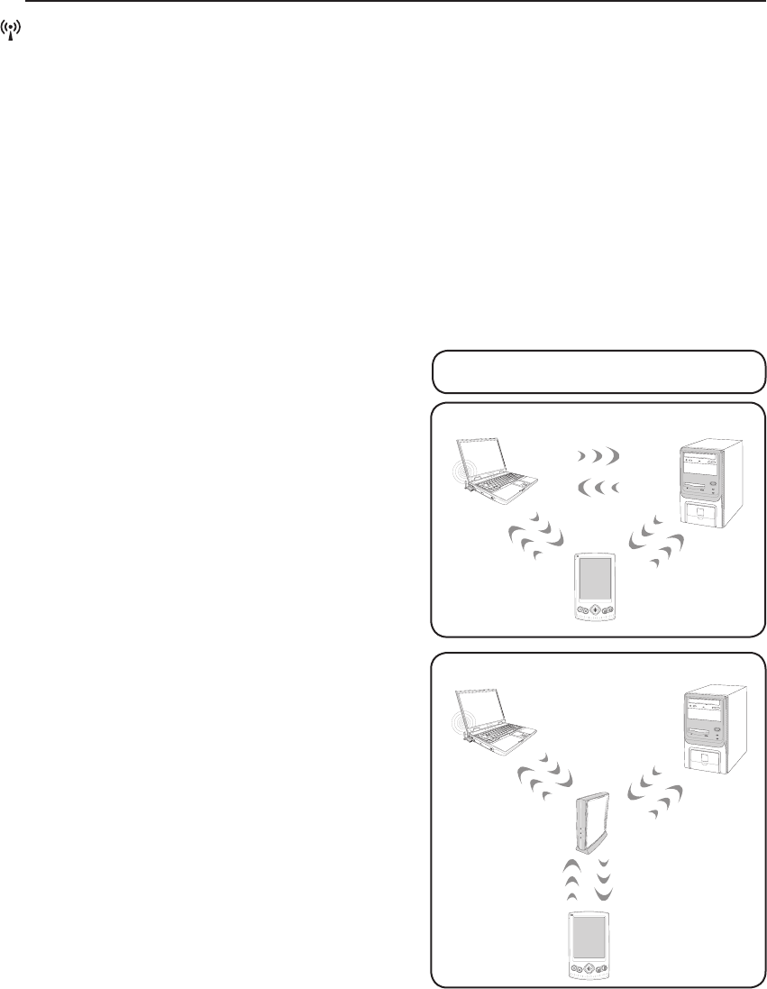
Infrastructure mode
The Infrastructure mode allows the Notebook PC and
other wireless devices to join a wireless network cre-
ated by an Access Point (AP) (sold separately) that
provides a central link for wireless clients to commu-
nicate with each other or with a wired network.
(All devices must install optional 802.11 wireless LAN adapters.)
Ad-hoc mode
The Ad-hoc mode allows the Notebook PC to connect
to another wireless device. No access point (AP) is
required in this wireless environment.
(All devices must install optional 802.11 wireless LAN adapters.)
These are examples of the Notebook PC
connected to a Wireless Network.
Desktop PC
PDA
Notebook PC
Access
Point
Desktop PC
PDA
Notebook PC
45
Using the Notebook PC 4
1
2
3
4
5
6
7
*
#
8
0
9
g
p
t
j
a
d
m
?
w
+
a/A
ㄅ
ㄉㄚ
ㄓㄗ
ㄢㄦ
ㄕㄙ
ㄤㄨ
ㄖㄥ
ㄩ
ㄔㄘ
ㄣㄧ
ㄍㄐㄞ
ㄎㄑㄟ
ㄆ
ㄊㄛ
ㄏㄒ
ㄠㄡ
ㄇ
ㄜㄋ
ㄌ
ㄈㄝ
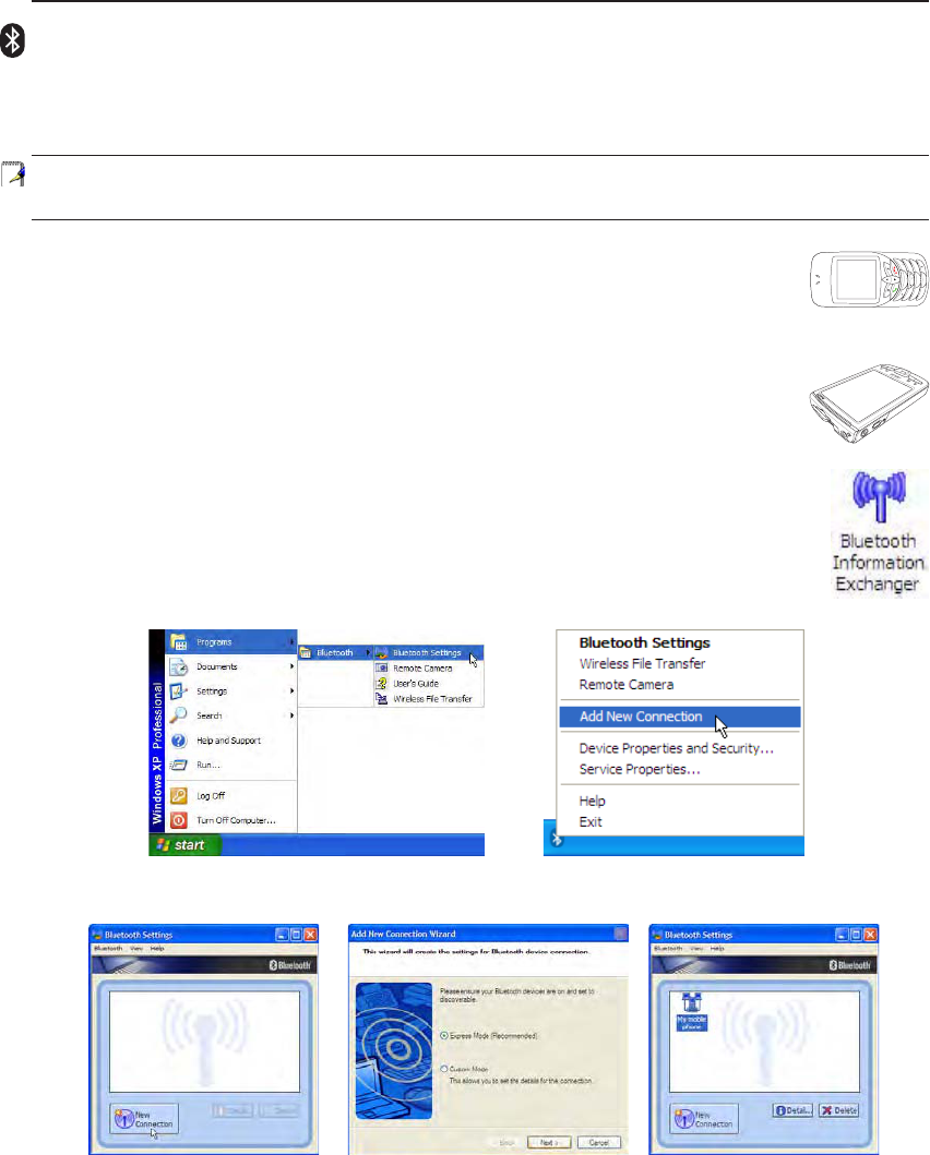
Bluetooth Wireless Connection (on selected models)
Notebook PCs with Bluetooth technology eliminates the need for cables for connecting Bluetooth-en-
abled devices. Examples of Bluetooth-enabled devices may be Notebook PCs, Desktop PCs, mobile
phones, and PDAs.
Note: If your Notebook PC did not come with built-in Bluetooth, you need to connect
a USB or PC Card Bluetooth module in order to use Bluetooth.
Bluetooth-enabled mobile phones
You can wireless connect to your mobile phone. Depending on your mobile phone’s ca-
pabilities, you can transfer phone book data, photos, sound les, etc. or use it as a modem
to connect to the Internet. You may also use it for SMS messaging.
Bluetooth-enabled computers or PDAs
You can wireless connect to another computer or PDA and exchange les, share peripherals,
or share Internet or network connections. You may also make use of Bluetooth-enabled
wireless keyboard or mouse.
Add New Connection from the
Bluetooth taskbar icon
Bluetooth Settings from Windows Start |
Programs | Bluetooth
Click New Connection from
Bluetooth Settings. Follow the wizard to add Bluetooth
devices. After complete, you should see
your device in the window.
Pairing with Bluetooth-enabled devices
You rst need to pair your Notebook PC with a Bluetooth-enabled device before you can
connect to it. Make sure the Bluetooth-enabled device is turned ON and ready to accept a
pair. Launch Bluetooth Settings from Windows Start | Programs | Bluetooth or select
Add New Connection from the Bluetooth taskbar icon if available.
46
4 Using the Notebook PC
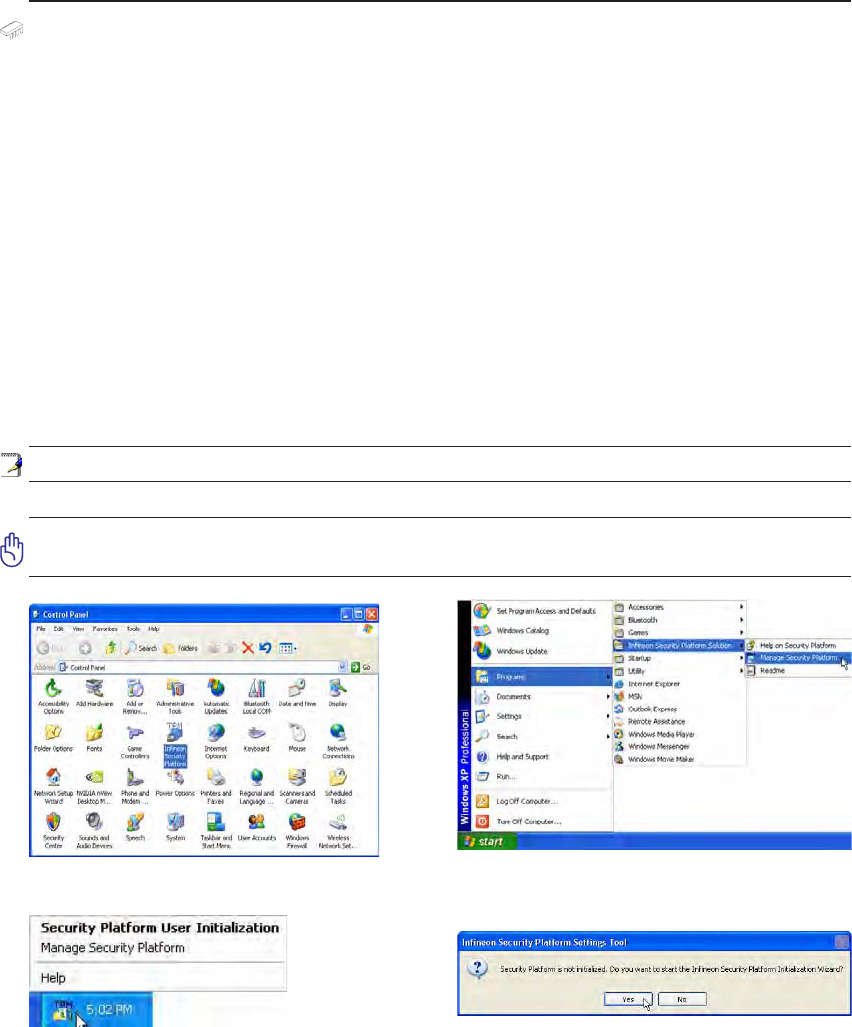
Trusted Platform Module (TPM) (on selected models)
The TPM, or Trusted Platform Module, is a security hardware device on the system board that will hold
computer-generated keys for encryption. It is a hardware-based solution that an help avoid attacks by
hackers looking to capture passwords and encryption keys to sensitive data. The TPM provides the abil-
ity to the PC or notebook to run applications more secure and to make transactions and communication
more trustworthy.
The secrity features provided by the TPM are internally supported by the following cryptographic capa-
bilities of each TPM: hashing, random number generation, asymmetric key generation, and asymmetric
encryption/decryption. Each individual TPM on each individual computer system has a unique signature
initialized during the silicon manufacturing process that further enhances its trust/security effectiveness.
Each individual TPM must have an Owner before it is useful as a security device.
TPM Applications
TPM is useful for any customer that is interested in providing an addition layer of security to the com-
puter system. The TPM, when bundled with an optional security software package, can provide overall
system security, le protection capabilities and protect against email/privacy concerns. TPM helps
provide security that can be stronger than that contained in the system BIOS, operating system, or any
non-TPM application.
Note: The TPM is disabled by default. Use BIOS setup to enable it.
Important: Use your TPM application’s “Restore” or “Migration” function to backup
your TPM security data.
TPM
You can launch the Security Platform application from
Windows “Control Panel”.
You can launch the Security Platform application from
Windows “Start” menu.
When the Security Platform is running, this icon will show in
the Windows taskbar. You can choose to initialize or manage
here.
When you launch the Security Platform application for the
rst time, answer Yes and follow the instructions to congure
it.

47
Using the Notebook PC 4
Power Management Modes
The Notebook PC has a number of automatic or adjustable power saving features that you can use to
maximize battery life and lower Total Cost of Ownership (TCO). You can control some of these features
through the Power menu in the BIOS Setup. ACPI power management settings are made through the
operating system. The power management features are designed to save as much electricity as possible
by putting components into a low power consumption mode as often as possible but also allow full
operation on demand. These low power modes are referred to as “Stand by” (or Suspend-to-RAM) and
“Hibernation” mode or Suspend-to-Disk (STD). The Standby mode is a simple function provided by the
operating system. When the Notebook PC is in either one of the power saving modes, the status will be
shown by the following: “Stand by”: Power LED Blinks and “Hibernation”: Power LED OFF.
Full Power Mode & Maximum Performance
The Notebook PC operates in Full Power mode when the power management function is disabled by
conguring Windows power management and SpeedStep. When the Notebook PC is operating in Full
Power Mode, the Power LED remains ON. If you are conscious of both system performance and power
consumption, select “Maximum Performance” instead of disabling all power management features.
ACPI
Advanced Conguration and Power Management (ACPI) was developed by Intel, Microsoft, and Toshiba
especially for Windows and later to control power management and Plug and Play features. ACPI is the
new standard in power management for Notebook PCs.
NOTE: APM was used in older operating systems like Windows NT4 and Windows 98.
Because newer operating systems like Windows XP, Windows 2000, and Windows ME
utilize ACPI, APM is no longer fully supported on this Notebook PC.
Suspend Mode
In “Stand by” (STR) and “Hibernation” (STD), the CPU clock is stopped and most of the Notebook PC
devices are put in their lowest active state. The suspend mode is the lowest power state of the Notebook
PC. The Notebook PC enters suspend mode when the system remains idle for a specied amount of time
or manually using the [Fn][F1] keys. The Power LED blinks when the Notebook PC is in STR mode.
In STD mode, the Notebook PC will appear to be powered OFF. Recover from STR by pressing any
keyboard button (except Fn). Recover from STD by using the power switch (just like powering
ON the Notebook PC).
Power Savings
In addition to reducing the CPU clock, this mode puts devices including the LCD backlight in their lower
active state. The Notebook PC enters “Stand by” mode (low priority) when the system remains idle for a
specied amount of time. The time-out can be set through Windows power management (higher priority).
To resume system operation, press any key.

48
4 Using the Notebook PC
Thermal Power Control
There are three power control methods for controlling the Notebook PC’s thermal state. These power
control cannot be congured by the user and should be known in case the Notebook PC should enter
these states. The following temperatures represent the chassis temperature (not CPU).
• The fan turns ON for active cooling when the temperature reaches the safe upper limit.
• The CPU decreases speed for passive cooling when the temperature exceeds the safe upper limit.
• The system shut down for critical cooling when temperature exceeds the maximum safe upper
limit.
Power State Summary
STATE ENTRY EVENT EXIT EVENT
“Stand by”
• “Stand by” through Windows Start button
• Timer as set though “Power Management” in
Windows Control Panel (higher priority)
• Any device
• Battery low
STR (“Stand by”)
(Suspend-to-RAM)
• Hotkey (see “Colored Hotkeys” under “Special
Keyboard Functions” in the previous section)
• Signal from modem port
• Power button or any key
STD (“Hibernate”)
(Suspend-to-Disk)
• Hotkey (see “Colored Hotkeys” under “Special
Keyboard Functions” in the previous section)
• Power button
Soft OFF • Power button (can be dened as STR or STD)
• “Shut down” through Windows Start button
• Power button
49
Using the Notebook PC 4
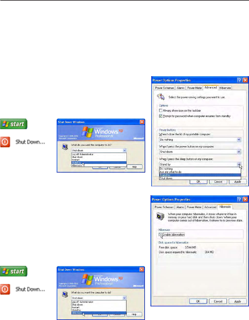
Stand by and Hibernate
Power management settings can be found in the Windows control panel. The following shows the power
options properties in Windows. You can dene “Stand By” or “Shut down” for closing the display panel,
pressing the power button, or activating sleep mode. “Stand by” and “Hibernate” saves power when
your Notebook PC is not in use by turning OFF certain components. When you resume your work, your
last status (such as a document scrolled down half way or email typed half way) will reappear as if you
never left. “Shut down” will close all applications and ask if you want to save your work if any are not
saved.
“Stand by” is the same as Suspend-to-RAM (STR). This
function stores your current data and status in RAM while
many components are turned OFF. Because RAM is volatile,
it requires power to keep (refresh) the data. To operate: select
“Start” | “Shut down”, and “Stand by”.
“Hibernate” is the same as Suspend-to-Disk (STD) and
stores your current data and status on the hard disk drive. By
doing this, RAM does not have to be periodically refreshed
and power consumption is greatly reduced but not completely
eliminated because certain wake-up components like LAN
needs to remain powered. “Hibernate” saves more power
compared to “Stand by”. To operate: Enable hibernation
in “Power Options” and select “Start” | “Shut down”, and
“Hibernate”.
50
4 Using the Notebook PC
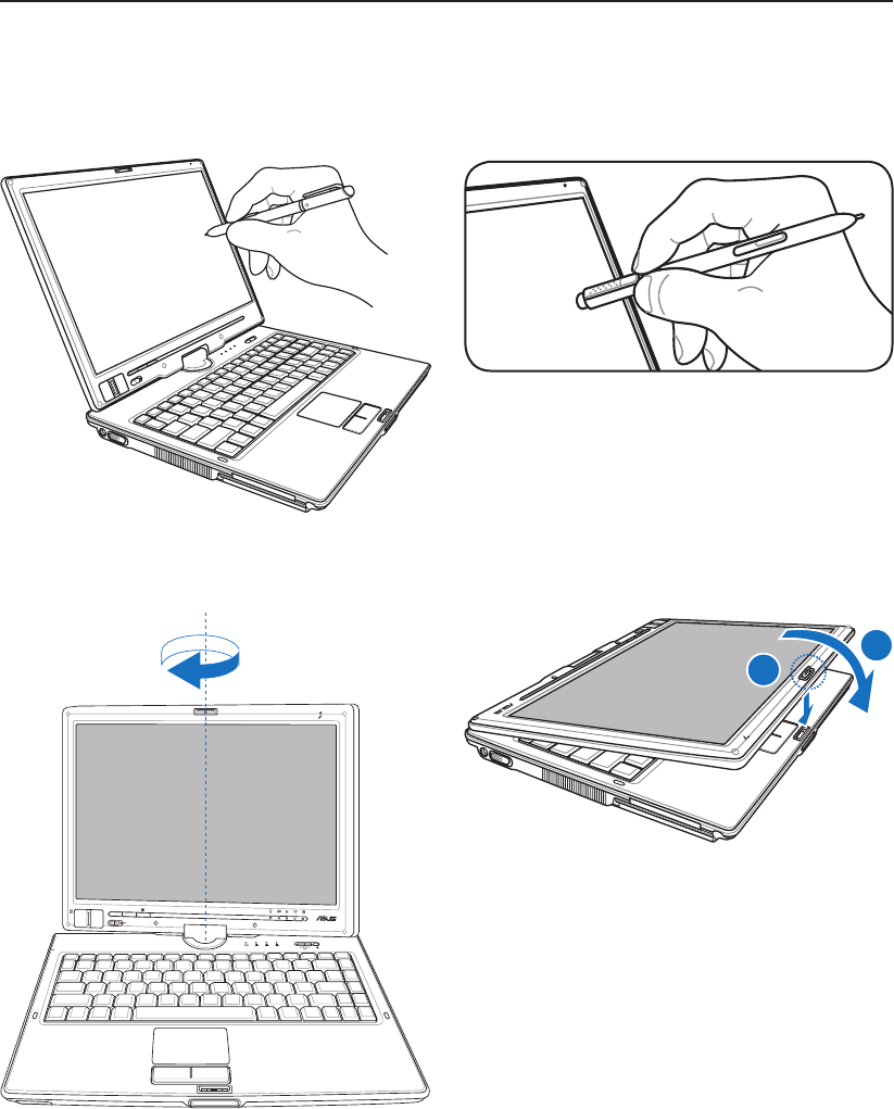
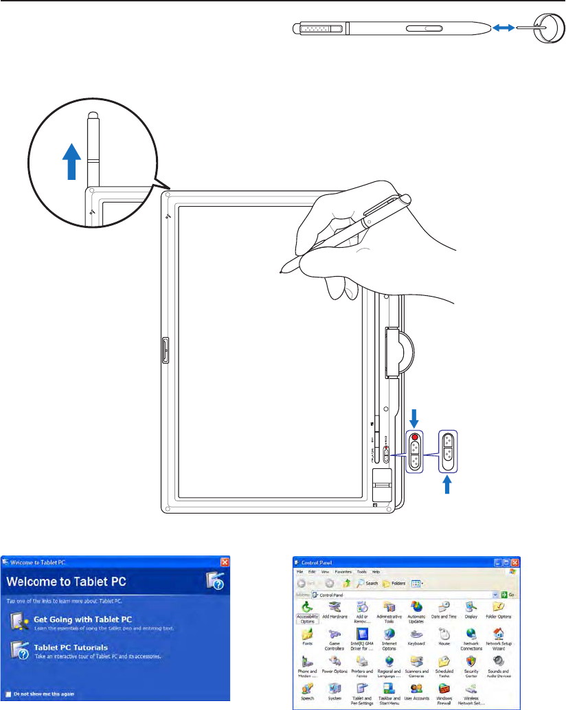
Tablet PC Mode
The following are illustrations for using the tablet PC function.
Use the tip of the tablet PC pen to activate the writing
function.
Use the back of the tablet PC pen to activate the erasing
function.
Rotate the display panel vertically using both hands to
support the sides of the display panel from rocking.
When the display is rotated into the tablet PC mode, the
latch must be reversed in order to lock the display panel.
POWER
ON OFF
HOLD
ESC
CTRL.ALT.DEL
1
2
51
Using the Notebook PC 4
Tablet PC Mode (Cont.)
Windows “Control Panel” also provide “Tablet and
Pen Settings” to customize software settings for
Tablet PC use.
Information will be available to help you use the
Notebook PC in Tablet PC mode when you enter
Windows.
Over long-term use, the plastic tip on the touchscreen pen
needs replacing when it wears close to the pen. Use the
provided tool to remove and insert a new tip (also provided)
before the tip wears out.
Press this latch down to
lock the display panel.
Enable
keys.
Disable
keys.
Use the HOLD switch
to disable the keys on
the display panel from
accidental activation.
Keep this side with air vents
away from your body.
52
4 Using the Notebook PC
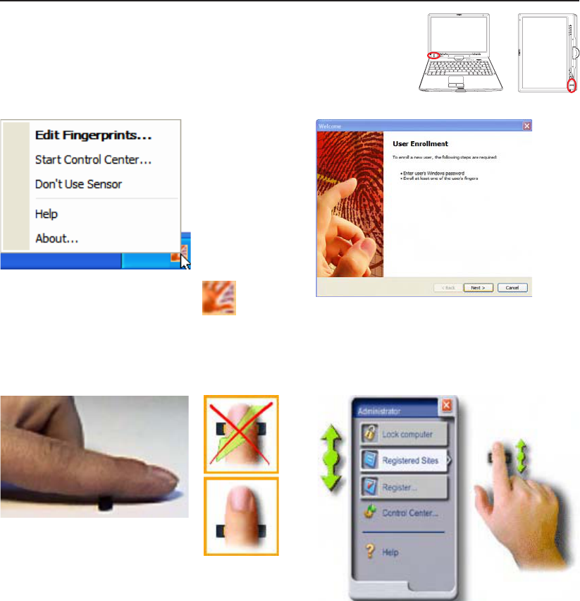
Fingerprint Scanner
The ngerprint scanner can be used either in the Notebook PC mode
or the Tablet PC mode.
After software setup, you can use the ngerprint scanner
as a scroll wheel like that on a mouse.
Left or right click the ngerprint taskbar
icon to open the menu to edit ngerprints
or make control settings. If you have not congured a user, you will be
directed to the “User Enrollment”. Follow the
instructions to setup the ngerprint scanner.
Scanning your ngerprint requires that
your nger be straight and at as shown
here.
53
Appendix
Optional Accessories
Optional Connections
Glossary
Declarations and Safety Statements
Notebook PC Information
54
A Appendix
Optional Accessories
These items, if desired, come as optional items to complement your Notebook PC.
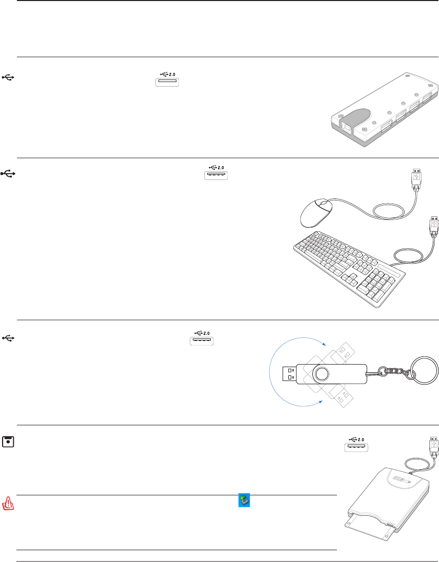
USB Flash Memory Disk
A USB ash memory disk is an optional item that can
replace the 1.44MB oppy disk and provide storage up
to several hundred megabytes, higher transfer speeds, and
greater durability. When used in current operating systems,
no drivers are necessary.
USB Hub (Optional)
Attaching an optional USB hub will increase your USB ports and allow
you to quickly connect or disconnect many USB peripherals through a
single cable.
USB Keyboard and Mouse
Attaching an external USB keyboard will allow data entry to be
more comfortable. Attaching an external USB mouse will allow
Windows navigation to be more comfortable. Both the external
USB keyboard and mouse will work simultaneously with the
Notebook PC’s built-in keyboard and touchpad.
WARNING! To prevent system failures, use (Safely Remove
Hardware) on the taskbar before disconnecting the USB oppy
disk drive. Eject the oppy disk before transporting the Notebook
PC to prevent damage from shock.
USB Floppy Disk Drive
An optional USB-interface oppy disk drive can accept a standard 1.44MB (or
720KB) 3.5-inch oppy diskette.
55
Appendix A
Optional Connections
These items, if desired, may be purchased from third-parties.
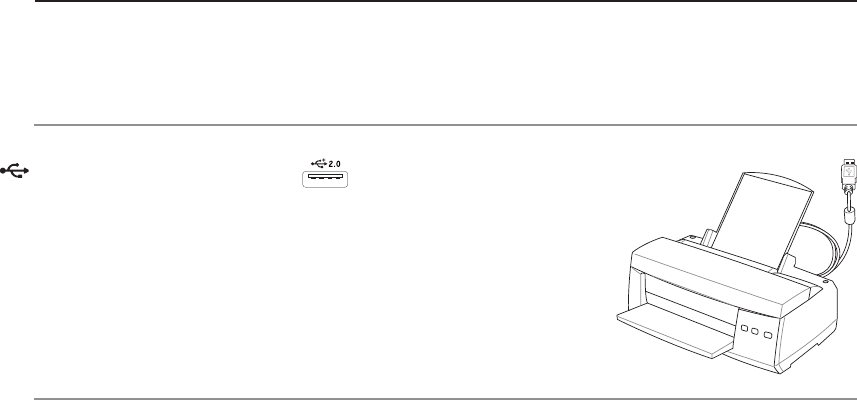
Printer Connection
One or more USB printers can be simultaneously used on any USB port
or USB hub.
56
A Appendix
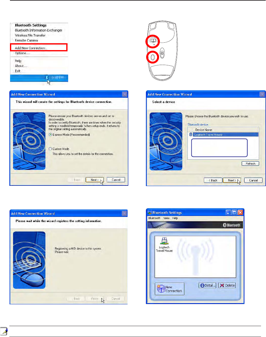
1. A Bluetooth icon
should be located on
your Windows taskbar.
Right click the taskbar
Bluetooth icon and
choose Add New
Connection.
4. Select “Express Mode” and click Next.
3. Push the “RESET” button on
the bottom of the mouse.
2. Turn ON the switch on the
bottom of the mouse.
5. A list of available Bluetooth devices will appear.
Select “Logitech Travel Mouse” and click Next.
6. The software will register the Bluetooth mouse.
Click Finish when complete.
7. A mouse icon with a pair of green and
yellow hands will show in this window.
R
E
S
E
T
OFF ON
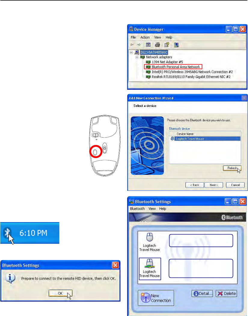
If you do not see the Bluetooth
mouse here. Push the “RESET”
button on the bottom of the
mouse and click Refresh here.
Note: “RESET” may be necessary after changing batteries. Repeat steps if necessary.
Setup Instructions
57
Appendix A
Troubleshooting
In “Device Manager”, check if “Bluetooth Personal
Area Network” is available as shown here.
Question: I cannot see my Bluetooth
mouse in the list. What do I do?
Double-click on the
Bluetooth Icon.
Double-click on the
registered Bluetooth mouse.
After connection, the icon
will show a pair of green and
yellow hands.
Click Refresh in the software and
“RESET” on the mouse. Repeat if
necessary.
Question: I already registered the
Bluetooth mouse before. Why is it not
working now? How do I connect to it?
Question: How do I check if my Bluetooth
is ready?
A prompt will appear for conrmation. Click OK.
R
E
S
E
T
OFF ON

58
A Appendix
Glossary
ACPI (Advanced Conguration and Power Management Interface)
Modern standard for reducing power usage in computers.
APM (Advanced Power Management)
Modern standard for reducing power usage in computers.
AWG (American Wire Gauge)
NOTE: This table is for general reference only and should not be used as a source of
the American Wire Gauge standard as this table may not be current or complete.
Gauge Diam Area R I@3A/mm2
AWG (mm) (mm2) (ohm/km) (mA)
33 0.18 0.026 676 75
0.19 0.028 605 85
32 0.20 0.031 547 93
30 0.25 0.049 351 147
29 0.30 0.071 243 212
27 0.35 0.096 178 288
26 0.40 0.13 137 378
25 0.45 0.16 108 477
Gauge Diam Area R I@3A/mm2
AWG (mm) (mm2) (ohm/km) (mA)
24 0.50 0.20 87.5 588
0.55 0.24 72.3 715
0.60 0.28 60.7 850
22 0.65 0.33 51.7 1.0 A
0.70 0.39 44.6 1.16 A
0.75 0.44 38.9 1.32 A
20 0.80 0.50 34.1 1.51 A
0.85 0.57 30.2 1.70 A
BIOS (Basic Input/Output System)
BIOS is a set of routines that affect how the computer transfers data between computer components, such
as memory, disks, and the display adapter. The BIOS instructions are built into the computer’s read-only
memory. BIOS parameters can be congured by the user through the BIOS Setup program. The BIOS
can be updated using the provided utility to copy a new BIOS le into the EEPROM.
Bit (Binary Digit)
Represents the smallest unit of data used by the computer. A bit can have one of two values: 0 or 1.
Boot
Boot means to start the computer operating system by loading it into system memory. When the manual
instructs you to “boot” your system (or computer), it means to turn ON your computer. “Reboot” means
to restart your computer. When using Windows 95 or later, selecting “Restart” from “Start | Shut Down...”
will reboot your computer.
Bluetooth (on selected models)
Bluetooth is a short-range wireless technology that lets you connect computers, mobile phones, and
handheld devices to each other and to the Internet. Bluetooth technology eliminates the ned for the cables
that connect devices together. Bluetooth-enabled devices connect wirelessly within a 10 m range.
Byte (Binary Term)
One byte is a group of eight contiguous bits. A byte is used to represent a single alphanumeric character,
punctuation mark, or other symbol.

59
Appendix A
Clock Throttling
Chipset function which allows the processor’s clock to be stopped and started at a known duty cycle.
Clock throttling is used for power savings, thermal management, and reducing processing speed.
CPU (Central Processing Unit)
The CPU, sometimes called “Processor,” actually functions as the “brain” of the computer. It interprets
and executes program commands and processes data stored in memory.
Device Driver
A device driver is a special set of instructions that allows the computer’s operating system to communicate
with devices such as VGA, audio, Ethernet, printer, or modem.
DVD
DVD is essentially a bigger, faster CD that can hold video as well as audio and computer data. With these
capacities and access rates, DVD discs can provide you with dramatically-enhanced high-color, full-mo-
tion videos, better graphics, sharper pictures, and digital audio for a theater-like experience. DVD aims
to encompass home entertainment, computers, and business information with a single digital format,
eventually replacing audio CD, videotape, laserdisc, CD-ROM, and video game cartridges.
ExpressCard
ExpressCard slot is 26 pins and support one ExpressCard/34mm or one ExpressCard/54mm expansion
card. This new interface is faster by using a serial bus supporting USB 2.0 and PCI Express instead of
the slower parallel bus used in the PC card slot. (Not compatible with previous PCMCIA cards.)
Hardware
Hardware is a general term referring to the physical components of a computer system, including pe-
ripherals such as printers, modems, and pointing devices.
IDE (Integrated Drive Electronics)
IDE devices integrate the drive control circuitry directly on the drive itself, eliminating the need for a
separate adapter card (in the case for SCSI devices). UltraDMA/66 or 100 IDE devices can achieve up
to 33MB/Sec transfer.
IEEE1394 (1394)
Also known as iLINK (Sony) or FireWire (Apple). 1394 is a high speed serial bus like SCSI but has
simple connections and hot-plugging capabilities like USB. The popular 1394a interface has a bandwidth
of 400Mbits/sec and can handle up to 63 units on the same bus. The newer 1394b interface can support
twice the speed and will appear in future models when peripherals support higher speeds. It is very likely
that 1394, together with USB, will replace Parallel, IDE, SCSI, and EIDE ports. 1394 is also used in
high-end digital equipment and should be marked “DV” for Digital Video port.
Infrared Port (IrDA) (on selected models)
The infrared (IrDA) communication port allows convenient wireless data communication with infra-
red-equipped devices or computers up to 4Mbits/sec. This allows easy wireless synchronization with
PDAs or mobile phones and even wireless printing to printers. Small ofces can use IrDA technology to
share a printer between several closely placed Notebook PCs and even send les to each other without
a network.

60
A Appendix
Kensington® Locks
Kensington® locks (or compatible) allow the Notebook PC to be secured usually using a metal cable and
lock that prevent the Notebook PC to be removed from a xed object. Some security products may also
include a motion detector to sound an alarm when moved.
Laser Classications
As lasers became more numerous and more widely used, the need to warn users of laser hazards became
apparent. To meet this need, laser classications were established. Current classication levels vary from
optically safe, requiring no controls (Class 1) to very hazardous, requiring strict controls (Class 4).
CLASS 1: A Class 1 laser or laser system emits levels of optical energy that are eye-safe and conse-
quently require no controls. An example of this class of laser system is the checkout scanning device
found in most grocery stores or lasers used in optical drives.
CLASS 2 & CLASS 3A: Class 2 and Class 3A lasers emit visible, continuous-wave (CW) optical
radiation levels slightly above the maximum permissible exposure (MPE) level. Although these
lasers can cause eye damage, their brightness usually causes observers to look away or blink before
eye damage occurs. These lasers have strict administrative controls requiring placement of signs
warning personnel not to stare directly into the beam. Class 3A lasers must not be viewed with opti-
cally-aided devices.
CLASS 3B: Class 3B lasers, and Class 3A lasers with outputs of 2.5mW, are hazardous to personnel
who are within the beam path and look at the beam source directly or by specular reection. These
lasers cannot produce hazardous diffuse reections. Personnel working with these lasers should wear
appropriate protective eyewear during any operation of the laser. Class 3B lasers have both administra-
tive and physical controls to protect personnel. Physical controls include limited access work areas.
Administrative controls include special warning signs posted outside the entrances to the laser work
spaces and lights outside the entrances that warn personnel when the lasers are in use.
CLASS 4: Class 4 lasers are high-power lasers that will cause damage to unprotected eyes and skin
through intra-beam viewing and specular or diffuse reections. Consequently, no personnel should
be in a room where a Class 4 laser is operating without proper eye protection.
PCI Bus (Peripheral Component Interconnect Local Bus)
PCI bus is a specication that denes a 32-bit data bus interface. PCI is a standard widely used by ex-
pansion card manufacturers.
POST (Power On Self Test)
When you turn on the computer, it will rst run through the POST, a series of software-controlled diag-
nostic tests. The POST checks system memory, the motherboard circuitry, the display, the keyboard, the
diskette drive, and other I/O devices.

61
Appendix A
RAM (Random Access Memory)
RAM (usually just called memory) is the place in a computer where the operating system, applica-
tion programs, and data in current use are temporarily kept so that they can be quickly reached by the
computer’s processor instead of having to read from and write to slower storage such as the hard disk
or optical disc.
Suspend Mode
In Save-to-RAM (STR) and Save-to-Disk (STD), the CPU clock is stopped and most of the Notebook PC
devices are put in their lowest active state. The Notebook PC enters Suspend when the system remains
idle for a specied amount of time or manually using the function keys. The time-out setting of both
Hard Disk and Video can be set by the BIOS Setup. The Power LED blinks when the Notebook PC is
in STR mode. In STD mode, the Notebook PC will appear to be powered OFF.
System Disk
A system disk contains the core le of an operating system and is used to boot up the operating system.
TPM (Trusted Platform Module) (on selected models)
The TPM is a security hardware device on the system board that will hold computer-generated keys for
encryption. It is a hardware-based solution that can help avoid attacks by hackers looking to capture
passwords and encryption keys to sensitive data. The TPM provides the ability to the PC or Notebook
PC to run applications more secure and to make transactions and communication more trustworthy.
Twisted-Pair Cable
The cable used to connect the Ethernet card to a host (generally a Hub or Switch) is called a straight-
through Twisted Pair Ethernet (TPE). The end connectors are called RJ-45 connectors, which are not
compatible with RJ-11 telephone connectors. If connecting two computers together without a hub in
between, a crossover twisted-pair is required.
UltraDMA/66 or 100
UltraDMA/66 or 100 are new specications to improve IDE transfer rates. Unlike traditional PIO mode,
which only uses the rising edge of IDE command signal to transfer data, UltraDMA/66 or 100 uses both
rising edge and falling edge.
USB (Universal Serial Bus)
A new 4-pin serial peripheral bus that allows plug and play computer peripherals such as keyboard,
mouse, joystick, scanner, printer and modem/ISDN to be automatically congured when they are at-
tached physically without having to install drivers or reboot. With USB, the traditional complex cables
from back panel of your PC can be eliminated.

62
A Appendix
Declarations and Safety Statements
DVD-ROM Drive Information
The Notebook PC comes with an optional DVD-ROM drive or a CD-ROM drive. In order to view DVD
titles, you must install your own DVD viewer software. Optional DVD viewer software may be purchased
with this Notebook PC. The DVD-ROM drive allows the use of both CD and DVD discs.
Regional Playback Information
Playback of DVD movie titles involves decoding MPEG2 video, digital AC3 audio and decryption of CSS
protected content. CSS (sometimes called copy guard) is the name given to the content protection scheme
adopted by the motion picture industry to satisfy a need to protect against unlawful content duplication.
Although the design rules imposed on CSS licensors are many, one rule that is most relevant is playback re-
strictions on regionalized content. In order to facilitate geographically staggered movie releases, DVD video
titles are released for specic geographic regions as dened in “Region Denitions” below. Copyright laws
require that all DVD movies be limited to a particular region (usually coded to the region at which it is sold).
While DVD movie content may be released for multiple regions, CSS design rules require that any system
capable of playing CSS encrypted content must only be capable of playing one region.
Region Denitions
Region 1
Canada, US, US Territories
Region 2
Czech, Egypt, Finland, France, Germany, Gulf States, Hungary, Iceland, Iran, Iraq, Ireland, Italy, Japan,
Netherlands, Norway, Poland, Portugal, Saudi Arabia, Scotland, South Africa, Spain, Sweden, Switzer-
land, Syria, Turkey, UK, Greece, Former Yugoslav Republics, Slovakia
Region 3
Burma, Indonesia, South Korea, Malaysia, Philippines, Singapore, Taiwan, Thailand, Vietnam
Region 4
Australia, Caribbean (Except US Territories), Central America, New Zealand, Pacic Islands, South
America
Region 5
CIS, India, Pakistan, Rest of Africa, Russia, North Korea
Region 6
China
NOTE: The region setting may be changed up to ve times using the viewer software,
then it can only play DVD movies for the last region setting. Changing the region code
after that will require factory resetting which is not covered by warranty. If resetting is
desired, shipping and resetting costs will be at the expense of the user.

63
Appendix A
Internal Modem Compliancy
The Notebook PC with internal modem model complies with JATE (Japan), FCC (US, Canada, Korea,
Taiwan), and CTR21. The internal modem has been approved in accordance with Council Decision
98/482/EC for pan-European single terminal connection to the public switched telephone network
(PSTN). However due to differences between the individual PSTNs provided in different countries, the
approval does not, of itself, give an unconditional assurance of successful operation on every PSTN
network termination point. In the event of problems you should contact your equipment supplier in the
rst instance.
Overview
On 4th August 1998 the European Council Decision regarding the CTR 21 has been published in the
Ofcial Journal of the EC. The CTR 21 applies to all non voice terminal equipment with DTMF-dialling
which is intended to be connected to the analogue PSTN (Public Switched Telephone Network).
CTR 21 (Common Technical Regulation) for the attachment requirements for connection to the analogue
public switched telephone networks of terminal equipment (excluding terminal equipment supporting
the voice telephony justied case service) in which network addressing, if provided, is by means of dual
tone multifrequency signalling.
Network Compatibility Declaration
Statement to be made by the manufacturer to the Notied Body and the vendor: “This declaration will
indicate the networks with which the equipment is designed to work and any notied networks with
which the equipment may have inter-working difculties”
Network Compatibility Declaration
Statement to be made by the manufacturer to the user: “This declaration will indicate the networks with
which the equipment is designed to work and any notied networks with which the equipment may
have inter-working difculties. The manufacturer shall also associate a statement to make it clear where
network compatibility is dependent on physical and software switch settings. It will also advise the user
to contact the vendor if it is desired to use the equipment on another network.”
Up to now the Notied Body of CETECOM issued several pan-European approvals using CTR 21. The
results are Europe’s rst modems which do not require regulatory approvals in each individual European
country.
Non-Voice Equipment
Answering machines and loud-speaking telephones can be eligible as well as modems, fax machines,
auto-dialers and alarm systems. Equipment in which the end-to-end quality of speech is controlled by
regulations (e.g. handset telephones and in some countries also cordless telephones) is excluded.

64
A Appendix
Internal Modem Compliancy (Cont.)
This table shows the countries currently under the CTR21 standard
.
Country Applied More Testing
Austria1 Yes No
Belgium Yes No
Czech Republic No Not Applicable
Denmark1 Yes Yes
Finland Yes No
France Yes No
Germany Yes No
Greece Yes No
Hungary No Not Applicable
Iceland Yes No
Ireland Yes No
Italy Still Pending Still Pending
Israel No No
Lichtenstein Yes No
Luxemburg Yes No
The Netherlands1 Yes Yes
Norway Yes No
Poland No Not Applicable
Portugal No Not Applicable
Spain No Not Applicable
Sweden Yes No
Switzerland Yes No
United Kingdom Yes No
This information was copied from CETECOM and is supplied without liability. For updates to this table,
you may visit http://www.cetecom.de/technologies/ctr_21.html
1 National requirements will apply only if the equipment may use pulse dialling (manufacturers may state
in the user guide that the equipment is only intended to support DTMF signalling, which would make
any additional testing superuous).
In The Netherlands additional testing is required for series connection and caller ID facilities.

Appendix A
65
Federal Communications Commission Statement
This device complies with FCC Rules Part 15. Operation is subject to the following two
conditions:
• This device may not cause harmful interference, and
• This device must accept any interference received, including interference that may cause
undesired operation.
This equipment has been tested and found to comply with the limits for a class B digital device,
pursuant to Part 15 of the Federal Communications Commission (FCC) rules. These limits are
designed to provide reasonable protection against harmful interference in a residential
installation. This equipment generates, uses, and can radiate radio frequency energy and, if not
installed and used in accordance with the instructions, may cause harmful interference to radio
communications. However, there is no guarantee that interference will not occur in a particular
installation. If this equipment does cause harmful interference to radio or television reception,
which can be determined by turning the equipment off and on, the user is encouraged to try to
correct the interference by one or more of the following measures:
• Reorient or relocate the receiving antenna.
• Increase the separation between the equipment and receiver.
• Connect the equipment into an outlet on a circuit different from that to which the receiver is
connected.
• Consult the dealer or an experienced radio/TV technician for help.
WARNING! The use of a shielded-type power cord is required in order to meet FCC emission limits and
to prevent interference to the nearby radio and television reception. It is essential that only the
supplied power cord be used. Use only shielded cables to connect I/O devices to this equipment. You
are cautioned that changes or modifications not expressly approved by the party responsible for
compliance could void your authority to operate the equipment.
(Reprinted from the Code of Federal Regulations #47, part 15.193, 1993. Washington DC: Office
of the Federal Register, National Archives and Records Administration, U.S. Government
Printing Office.)
IC Statement
Operation is subject to the following two conditions:
• This device may not cause interference and
• This device must accept any interference, including interference that may cause undesired
operation of the device.
To prevent radio interference to the licensed service (i.e. co-channel Mobile Satellite systems)
this device is intended to be operated indoors and away from windows to provide maximum
shielding. Equipment (or its transmit antenna) that is installed outdoors is subject to licensing.
Because high power radars are allocated as primary users (meaning they have priority) in
5250-5350 MHz, these radars could cause interference and/or damage to license exempt LAN
devices.

Appendix A
66
CE Mark Warning
This is a Class B product, in a domestic environment, this product may cause radio interference,
in which case the user may be required to take adequate measures.
FCC Radio Frequency Interference Requirements
This device is restricted to INDOOR USE due to its operation in the 5.15 to 5.25GHz frequency
range. FCC requires this product to be used indoors for the frequency range 5.15 to 5.25GHz to
reduce the potential for harmful interference to co-channel of the Mobile Satellite Systems. High
power radars are allocated as primary user of the 5.25 to 5.35GHz and 5.65 to 5.85GHz bands.
These radar stations can cause interference with and / or damage this device.
IMPORTANT: This device and its antenna(s) must not be co-located or operating in conjunction with
any other antenna or transmitter.
FCC Radio Frequency (RF) Exposure Caution Statement
FCC Caution: Any changes or modifications not expressly approved by the party responsible for
compliance could void the user’s authority to operate this equipment. “ASUS declare that this device
in the 2.4GHz is limited to Channels 1 through 11 by specified firmware controlled in the USA.”
This equipment complies with FCC radiation exposure limits set forth for an uncontrolled
environment. To maintain compliance with FCC RF exposure compliance requirements, please
avoid direct contact to the transmitting antenna during transmitting. End users must follow the
specific operating instructions for satisfying RF exposure compliance. For operation within
5.15GHz and 5.25GHz frequency ranges, it is restricted to indoor environment, and the antenna
of this device must be integral.
IC Radiation Exposure Statement
This equipment complies with IC radiation exposure limits set forth for an uncontrolled
environment. To maintain compliance with IC RF exposure compliance requirements, please
avoid direct contact to the transmitting antenna during transmitting. End users must follow the
specific operating instructions for satisfying RF exposure compliance.
Declaration of Conformity (R&TTE directive 1999/5/EC)
The following items were completed and are considered relevant and sufficient:
• Essential requirements as in [Article 3]
• Protection requirements for health and safety as in [Article 3.1a]
• Testing for electric safety according to [EN 60950]
• Protection requirements for electromagnetic compatibility in [Article 3.1b]
• Testing for electromagnetic compatibility in [EN 301 489-1] & [EN 301]
• Testing according to [489-17]
• Effective use of the radio spectrum as in [Article 3.2]
• Radio test suites according to [EN 300 328-2]

67
Appendix A
France Restricted Wireless Frequency Bands
Some areas of France have a restricted frequency band. The worst case maximum authorized power
indoors are:
• 10mW for the entire 2.4 GHz band (2400 MHz–2483.5 MHz)
• 100mW for frequencies between 2446.5 MHz and 2483.5 MHz
NOTE: Channels 10 through 13 inclusive operate in the band 2446.6 MHz to 2483.5 MHz.
There are few possibilities for outdoor use: On private property or on the private property of public
persons, use is subject to a preliminary authorization procedure by the Ministry of Defense, with maximum
authorized power of 100mW in the 2446.5–2483.5 MHz band. Use outdoors on public property is not
permitted.
In the departments listed below, for the entire 2.4 GHz band:
• Maximum authorized power indoors is 100mW
• Maximum authorized power outdoors is 10mW
Departments in which the use of the 2400–2483.5 MHz band is permitted with an EIRP of less than
100mW indoors and less than 10mW outdoors:
01 Ain Orientales 02 Aisne 03 Allier 05 Hautes Alpes
08 Ardennes 09 Ariège 11 Aude 12 Aveyron
16 Charente 24 Dordogne 25 Doubs 26 Drôme
32 Gers 36 Indre 37 Indre et Loire 41 Loir et Cher
45 Loiret 50 Manche 55 Meuse 58 Nièvre
59 Nord 60 Oise 61 Orne 63 Puy du Dôme
64 Pyrénées Atlantique 66 Pyrénées 67 Bas Rhin 68 Haut Rhin
70 Haute Saône 71 Saône et Loire 75 Paris 82 Tarn et Garonne
84 Vaucluse 88 Vosges 89 Yonne 90 Territoire de Belfort
94 Val de Marne
This requirement is likely to change over time, allowing you to use your wireless LAN card in more
areas within France. Please check with ART for the latest information (www.art-telecom.fr)
NOTE: Your WLAN Card transmits less than 100mW, but more than 10mW.
Wireless Operation Channel for Different Domains
N. America 2.412-2.462 GHz Ch01 through CH11
Japan 2.412-2.484 GHz Ch01 through Ch14
Europe ETSI 2.412-2.472 GHz Ch01 through Ch13

68
A Appendix
UL Safety Notices
Required for UL 1459 covering telecommunications (telephone) equipment intended to be electrically
connected to a telecommunication network that has an operating voltage to ground that does not exceed
200V peak, 300V peak-to-peak, and 105V rms, and installed or used in accordance with the National
Electrical Code (NFPA 70).
When using the Notebook PC modem, basic safety precautions should always be followed to reduce the
risk of re, electric shock, and injury to persons, including the following:
• Do not use the Notebook PC near water, for example, near a bath tub, wash bowl, kitchen sink or
laundry tub, in a wet basement or near a swimming pool.
• Do not use the Notebook PC during an electrical storm. There may be a remote risk of electric shock
from lightning.
• Do not use the Notebook PC in the vicinity of a gas leak.
Required for UL 1642 covering primary (non-rechargeable) and secondary (rechargeable) lithium batter-
ies for use as power sources in products. These batteries contain metallic lithium, or a lithium alloy, or
a lithium ion, and may consist of a single electrochemical cell or two or more cells connected in series,
parallel, or both, that convert chemical energy into electrical energy by an irreversible or reversible
chemical reaction.
• Do not dispose the Notebook PC battery pack in a re, as they may explode. Check with local codes
for possible special disposal instructions to reduce the risk of injury to persons due to re or explo-
sion.
• Do not use power adapters or batteries from other devices to reduce the risk of injury to persons due
to re or explosion. Use only UL certied power adapters or batteries supplied by the manufacturer
or authorized retailers.
Power Safety Requirement
Products with electrical current ratings up to 6A and weighing more than 3Kg must use approved power
cords greater than or equal to: H05VV-F, 3G, 0.75mm2 or H05VV-F, 2G, 0.75mm2.
69
Appendix A
Nordic Lithium Cautions (for lithium-ion batteries)
CAUTION! Danger of explosion if battery is incorrectly replaced. Replace only with the same or equiva-
lent type recommended by the manufacturer. Dispose of used batteries according to the manufacturer’s
instructions. (English)
ATTENZIONE! Rischio di esplosione della batteria se sostituita in modo errato. Sostituire la batteria con
un una di tipo uguale o equivalente consigliata dalla fabbrica. Non disperdere le batterie nell’ambiente.
(Italian)
VORSICHT! Explosionsgetahr bei unsachgemäßen Austausch der Batterie. Ersatz nur durch denselben
oder einem vom Hersteller empfohlenem ähnlichen Typ. Entsorgung gebrauchter Batterien nach Angaben
des Herstellers. (German)
ADVARSELI! Lithiumbatteri - Eksplosionsfare ved fejlagtig håndtering. Udskiftning må kun ske med
batteri af samme fabrikat og type. Levér det brugte batteri tilbage til leverandøren. (Danish)
VARNING! Explosionsfara vid felaktigt batteribyte. Använd samma batterityp eller en ekvivalent typ som
rekommenderas av apparattillverkaren. Kassera använt batteri enligt fabrikantens instruktion. (Swedish)
VAROITUS! Paristo voi räjähtää, jos se on virheellisesti asennettu. Vaihda paristo ainoastaan laitevalmistajan
sousittelemaan tyyppiin. Hävitä käytetty paristo valmistagan ohjeiden mukaisesti. (Finnish)
ATTENTION! Il y a danger d’explosion s’il y a remplacement incorrect de la batterie. Remplacer
uniquement avec une batterie du mêre type ou d’un type équivalent recommandé par le constructeur.
Mettre au rebut les batteries usagées conformément aux instructions du fabricant. (French)
ADVARSEL! Eksplosjonsfare ved feilaktig skifte av batteri. Benytt samme batteritype eller en tilsvarende
type anbefalt av apparatfabrikanten. Brukte batterier kasseres i henhold til fabrikantens instruksjoner.
(Norwegian)
(Japanese)

70
A Appendix
Service warning label
WARNING: Making adjustments or performing procedures other than those specied
in the user’s manual may result in hazardous laser exposure. Do not attempt to disas-
semble the optical drive. For your safety, have the optical drive serviced only by an
authorized service provider.
CAUTION: INVISIBLE LASER RADIATION WHEN OPEN. DO NOT STARE INTO BEAM
OR VIEW DIRECTLY WITH OPTICAL INSTRUMENTS.
CDRH Regulations
The Center for Devices and Radiological Health (CDRH) of the U.S. Food and Drug Administration imple-
mented regulations for laser products on August 2, 1976. These regulations apply to laser products manu-
factured from August 1, 1976. Compliance is mandatory for products marketed in the United States.
WARNING: Use of controls or adjustments or performance of procedures other than
those specied herein or in the laser product installation guide may result in hazard-
ous radiation exposure.
Macrovision Corporation Product Notice
This product incorporates copyright protection technology that is protected by method claims of certain
U.S.A. patents and other intellectual property rights owned by Macrovision Corporation and other rights
owners. Use of this copyright protection technology must be authorized by Macrovision Corporation, and
is intended for home and other limited viewing uses only unless otherwise authorized by Macrovision
Corporation. Reverse engineering or disassembly is prohibited.
Optical Drive Safety Information
Laser Safety Information
Internal or external optical drives sold with this Notebook PC contains a CLASS 1 LASER PRODUCT.
Laser classications can be found in the glossary at the end of this user’s manual.
71
Appendix A
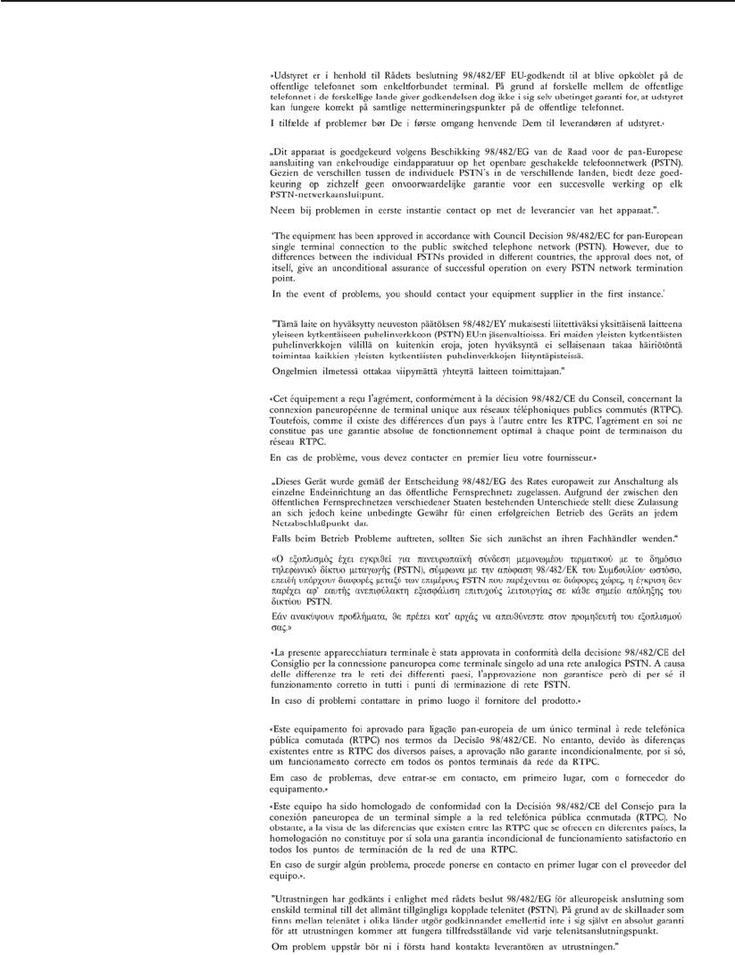
Danish
Dutch
English
Finnish
French
German
Greek
Italian
Portuguese
Spanish
Swedish
CTR 21 Approval (for Notebook PC with built-in Modem)

72
A Appendix
Notebook PC Information
This page is provided for recording information concerning your Notebook PC for future reference or
for technical support. Keep this User’s Manual in a secured location if passwords are lled out.
Owner’s Name: ___________________________ Owner’s Telephone: ______________
Manufacturer: _______________ Model: ___________ Serial Number: ______________
Display Size: ___________ Resolution: _____________Memory Size: ______________
Retailer: _________________Location: ___________ Purchase Date: ______________
Hard Drive Manufacturer: ____________________________ Capacity: ______________
Optical Drive Manufacturer: _____________________________ Type: ______________
BIOS Version: __________________________________________Date: ______________
Accessories: _____________________________________________________________
Accessories: _____________________________________________________________
Software
Operating System: __________Version: ___________ Serial Number: ______________
Software: _________________Version: ___________ Serial Number: ______________
Software: _________________Version: ___________ Serial Number: ______________
Security
Supervisor Name: _______________________ Supervisor Password: ______________
User Name: ___________________________________User Password: ______________
Network
User Name: ______________Password: _________________ Domain: ______________
User Name: ______________Password: _________________ Domain: ______________
Copyright Information
No part of this manual, including the products and software described in it, may be reproduced, trans-
mitted, transcribed, stored in a retrieval system, or translated into any language in any form or by any
means, except documentation kept by the purchaser for backup purposes, without the express written
permission of ASUSTeK COMPUTER INC. (“ASUS”).
ASUS PROVIDES THIS MANUAL “AS IS” WITHOUT WARRANTY OF ANY KIND, EITHER
EXPRESS OR IMPLIED, INCLUDING BUT NOT LIMITED TO THE IMPLIED WARRANTIES OR
CONDITIONS OF MERCHANTABILITY OR FITNESS FOR A PARTICULAR PURPOSE. IN NO
EVENT SHALL ASUS, ITS DIRECTORS, OFFICERS, EMPLOYEES OR AGENTS BE LIABLE
FOR ANY INDIRECT, SPECIAL, INCIDENTAL, OR CONSEQUENTIAL DAMAGES (INCLUDING
DAMAGES FOR LOSS OF PROFITS, LOSS OF BUSINESS, LOSS OF USE OR DATA, INTER-
RUPTION OF BUSINESS AND THE LIKE), EVEN IF ASUS HAS BEEN ADVISED OF THE POS-
SIBILITY OF SUCH DAMAGES ARISING FROM ANY DEFECT OR ERROR IN THIS MANUAL
OR PRODUCT.
Products and corporate names appearing in this manual may or may not be registered trademarks or
copyrights of their respective companies, and are used only for identication or explanation and to the
owners’ benet, without intent to infringe.
SPECIFICATIONS AND INFORMATION CONTAINED IN THIS MANUAL ARE FURNISHED FOR
INFORMATIONAL USE ONLY, AND ARE SUBJECT TO CHANGE AT ANY TIME WITHOUT NO-
TICE, AND SHOULD NOT BE CONSTRUED AS A COMMITMENT BY ASUS. ASUS ASSUMES NO
RESPONSIBILITY OR LIABILITY FOR ANY ERRORS OR INACCURACIES THAT MAY APPEAR
IN THIS MANUAL, INCLUDING THE PRODUCTS AND SOFTWARE DESCRIBED IN IT.
Copyright © 2006 ASUSTeK COMPUTER INC. All Rights Reserved.
Limitation of Liability
Circumstances may arise where because of a default on ASUS’ part or other liability, you are entitled to
recover damages from ASUS. In each such instance, regardless of the basis on which you are entitled
to claim damages from ASUS, ASUS is liable for no more than damages for bodily injury (including
death) and damage to real property and tangible personal property; or any other actual and direct dam-
ages resulted from omission or failure of performing legal duties under this Warranty Statement, up to
the listed contract price of each product.
ASUS will only be responsible for or indemnify you for loss, damages or claims based in contract, tort
or infringement under this Warranty Statement.
This limit also applies to ASUS’ suppliers and its reseller. It is the maximum for which ASUS, its sup-
pliers, and your reseller are collectively responsible.
UNDER NO CIRCUMSTANCES IS ASUS LIABLE FOR ANY OF THE FOLLOWING: (1) THIRD-
PARTY CLAIMS AGAINST YOU FOR DAMAGES; (2) LOSS OF, OR DAMAGE TO, YOUR RE-
CORDS OR DATA; OR (3) SPECIAL, INCIDENTAL, OR INDIRECT DAMAGES OR FOR ANY
ECONOMIC CONSEQUENTIAL DAMAGES (INCLUDING LOST PROFITS OR SAVINGS), EVEN
IF ASUS, ITS SUPPLIERS OR YOUR RESELLER IS INFORMED OF THEIR POSSIBILITY.
Service and Support
Visit our multi-language web site at http://support.asus.com