ASUSTeK Computer RTAC68U Wireless-AC1900 Dual Band Gigabit Router User Manual UserMan P48 P84
ASUSTeK Computer Inc Wireless-AC1900 Dual Band Gigabit Router UserMan P48 P84
Contents
- 1. UserMan-(P1-P47)
- 2. UserMan-(P48-P84)
- 3. UserMan-(P85-P129)
- 4. UserMan
- 5. Users manual
- 6. Users Manual
UserMan-(P48-P84)
47
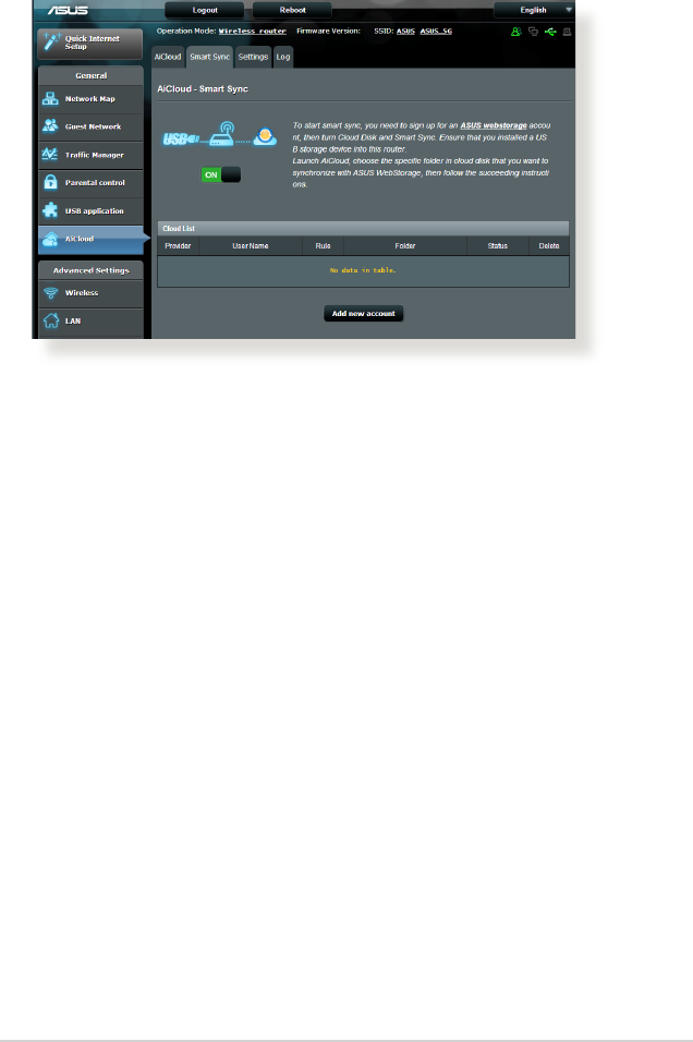
3.6.3 Smart Sync
To use Smart Sync:
1. Launch AiCloud, click Smart Sync > Go.
2. Select ON to enable Smart Sync.
3. Click Add new account.
4. Enter your ASUS WebStorage account password and select the
directory that you want to sync with WebStorage.
5. Click Apply.
48
4 Conguring the Advanced
Settings
4.1 Wireless
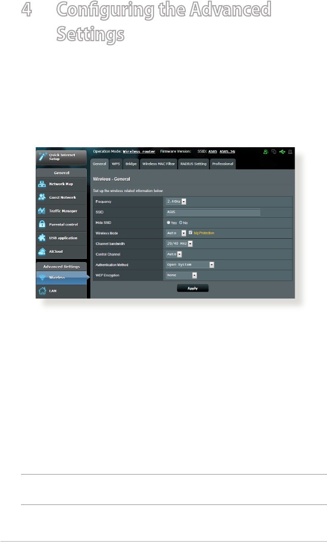
4.1.1 General
The General tab allows you to congure the basic wireless
settings.
To configure the basic wireless settings:
1. From the navigation panel, go to Advanced Settings >
Wireless > General tab.
2. Select 2.4GHz or 5GHz as the frequency band for your wireless
network.
3. Assign a unique name containing up to 32 characters for your
SSID (Service Set Identier) or network name to identify your
wireless network. Wi-Fi devices can identify and connect to
the wireless network via your assigned SSID. The SSIDs on the
information banner are updated once new SSIDs are saved to
the settings.
NOTE: You can assign unique SSIDs for the 2.4 GHz and 5GHz frequency
bands.

49
4. In the Hide SSID eld, select Yes to prevent wireless devices
from detecting your SSID. When this function is enabled, you
would need to enter the SSID manually on the wireless device
to access the wireless network.
5. Select any of these wireless mode options to determine the
types of wireless devices that can connect to your wireless
router:
Auto: Select Auto to allow 802.11AC, 802.11n, 802.11g, and
802.11b devices to connect to the wireless router.
Legacy: Select Legacy to allow 802.11b/g/n devices to
connect to the wireless router. Hardware that supports
802.11n natively, however, will only run at a maximum speed
of 54Mbps.
N only: Select N only to maximize wireless N performance.
This setting prevents 802.11g and 802.11b devices from
connecting to the wireless router.
6. Select the operating channel for your wireless router. Select
Auto to allow the wireless router to automatically select the
channel that has the least amount of interference.
7. Select any of these channel bandwidth to accommodate higher
transmission speeds:
40MHz: Select this bandwidth to maximize the wireless
throughput.
20MHz (default): Select this bandwidth if you encounter some
issues with your wireless connection.
8. Select any of these authentication methods:
• Open System: This option provides no security.
• Shared Key: You must use WEP encryption and enter at least
one shared key.
•
•
•

50
• WPA/WPA2 Personal/WPA Auto-Personal: This option
provides strong security. You can use either WPA (with
TKIP) or WPA2 (with AES). If you select this option, you must
use TKIP + AES encryption and enter the WPA passphrase
(network key).
• WPA/WPA2 Enterprise/WPA Auto-Enterprise: This option
provides very strong security. It is with integrated EAP server
or an external RADIUS back-end authentication server.
• Radius with 802.1x
NOTE: Your wireless router supports the maximum transmission rate
of 54Mbps when the Wireless Mode is set to Auto and encryption
method is WEP or TKIP.
9. Select any of these WEP (Wired Equivalent Privacy) Encryption
options for the data transmitted over your wireless network:
• O: Disables WEP encryption
• 64-bit: Enables weak WEP encryption
• 128-bit: Enables improved WEP encryption.
10.When done, click Apply.
51
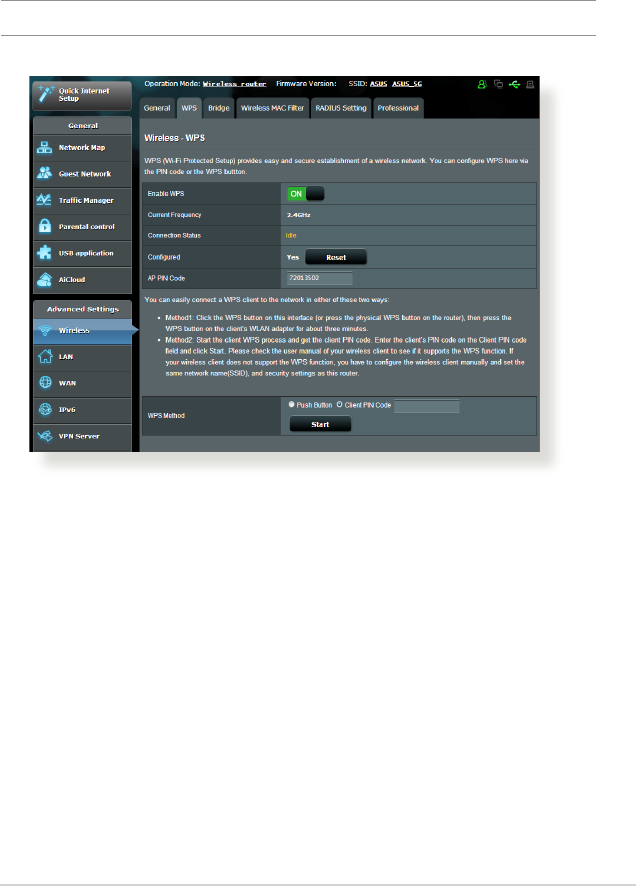
4.1.2 WPS
WPS (Wi-Fi Protected Setup) is a wireless security standard that
allows you to easily connect devices to a wireless network. You
can congure the WPS function via the PIN code or WPS button.
NOTE: Ensure that the devices support WPS.
To enable WPS on your wireless network:
1. From the navigation panel, go to Advanced Settings >
Wireless > WPS tab.
2. In the Enable WPS eld, move the slider to ON.
3. WPS uses 2.4GHz by default. If you want to change the
frequency to 5GHz, turn OFF the WPS function, click Switch
Frequency in the Current Frequency eld, and turn WPS ON
again.

52
NOTE: WPS supports authentication using Open System, WPA-Personal,
and WPA2-Personal. WPS does not support a wireless network that uses
a Shared Key, WPA-Enterprise, WPA2-Enterprise, and RADIUS encryption
method.
3. In the WPS Method eld, select Push Button or Client PIN
code. If you select Push Button, go to step 4. If you select
Client PIN code, go to step 5.
4. To set up WPS using the router’s WPS button, follow these
steps:
a. Click Start or press the WPS button found at the rear of the
wireless router.
b. Press the WPS button on your wireless device. This is
normally identied by the WPS logo.
Note: Check your wireless device or its user manual for the location of
the WPS button.
c. The wireless router will scan for any available WPS devices.
If the wireless router does not nd any WPS devices, it will
switch to standby mode.
5. To set up WPS using the Client’s PIN code, follow these steps:
a. Locate the WPS PIN code on your wireless device’s user
manual or on the device itself.
b. Key in the Client PIN code on the text box.
c. Click Start to put your wireless router into WPS survey mode.
The router’s LED indicators quickly ash three times until the
WPS setup is completed.
53
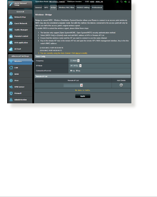
4.1.3 Bridge
Bridge or WDS (Wireless Distribution System) allows your ASUS
wireless router to connect to another wireless access point
exclusively, preventing other wireless devices or stations to access
your ASUS wireless router. It can also be considered as a wireless
repeater where your ASUS wireless router communicates with
another access point and other wireless devices.
To set up the wireless bridge:
1. From the navigation panel, go to Advanced Settings >
Wireless > Bridge tab.
2. Select the frequency band for the wireless bridge.
3. In the AP Mode eld, select any of these options:
• AP Only: Disables the Wireless Bridge function.
• WDS Only: Enables the Wireless Bridge feature but prevents
other wireless devices/stations from connecting to the
router.

54
• HYBRID: Enables the Wireless Bridge feature and allows
other wireless devices/stations to connect to the router.
NOTE: In Hybrid mode, wireless devices connected to the ASUS wireless
router will only receive half the connection speed of the Access Point.
4. In the Connect to APs in list eld, click Yes if you want to
connect to an Access Point listed in the Remote AP List.
5. In the Control Channel eld, select the operating channel
for the wireless bridge. Select Auto to allow the router to
automatically select the channel with the least amount of
interference.
NOTE: Channel availability varies per country or region.
6. On the Remote AP List, key in a MAC address and click the Add
button to enter the MAC address of other available Access
Points.
NOTE: Any Access Point added to the list should be on the same Control
Channel as the ASUS wireless router.
7. Click Apply.
55
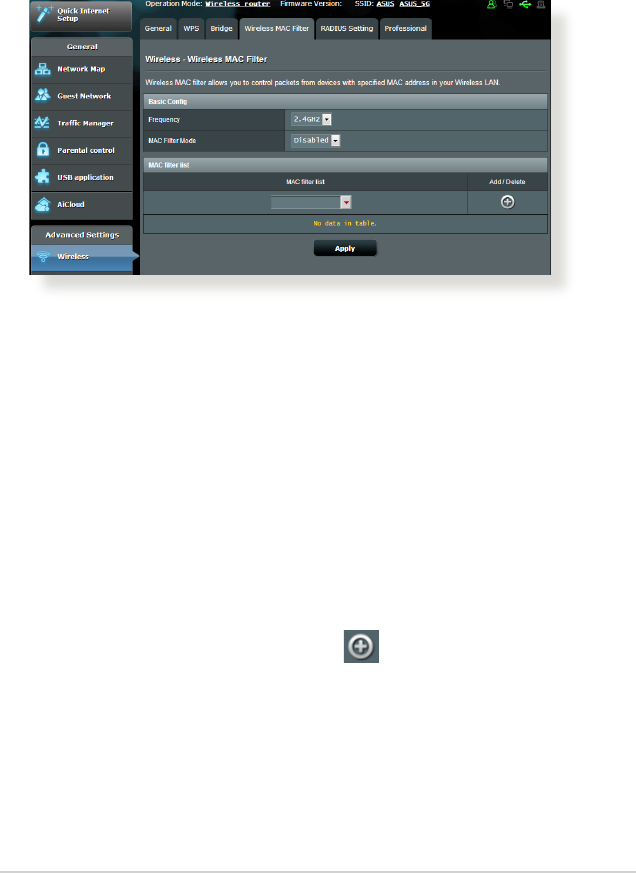
4.1.4 Wireless MAC Filter
Wireless MAC lter provides control over packets transmitted to
a specied MAC (Media Access Control) address on your wireless
network.
To set up the Wireless MAC lter:
1. From the navigation panel, go to Advanced Settings >
Wireless > Wireless MAC Filter tab.
2. In the Frequency eld, select the frequency band that you
want to use for the Wireless MAC lter.
3. In the MAC Filter Mode dropdown list, select either Accept or
Reject.
• Select Accept to allow devices in the MAC lter list to access
to the wireless network.
• Select Reject to prevent devices in the MAC lter list to
access to the wireless network.
4. On the MAC lter list, click the Add button and key in the
MAC address of the wireless device.
5. Click Apply.
56
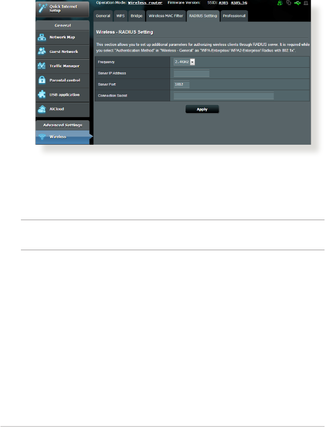
4.1.5 RADIUS Setting
RADIUS (Remote Authentication Dial In User Service) Setting
provides an extra layer of security when you choose WPA-
Enterprise, WPA2-Enterprise, or Radius with 802.1x as your
Authentication Mode.
To set up wireless RADIUS settings:
1. Ensure that the wireless router’s authentication mode is set to
WPA-Enterprise, WPA2-Enterprise, or Radius with 802.1x.
NOTE: Please refer to section 4.1.1 General section for conguring your
wireless router’s Authentication Mode.
2. From the navigation panel, go to Advanced Settings >
Wireless > RADIUS Setting.
3. Select the frequency band.
4. In the Server IP Address eld, key in your RADIUS server’s IP
Address.
5. In the Connection Secret eld, assign the password to access
your RADIUS server.
6. Click Apply.
57
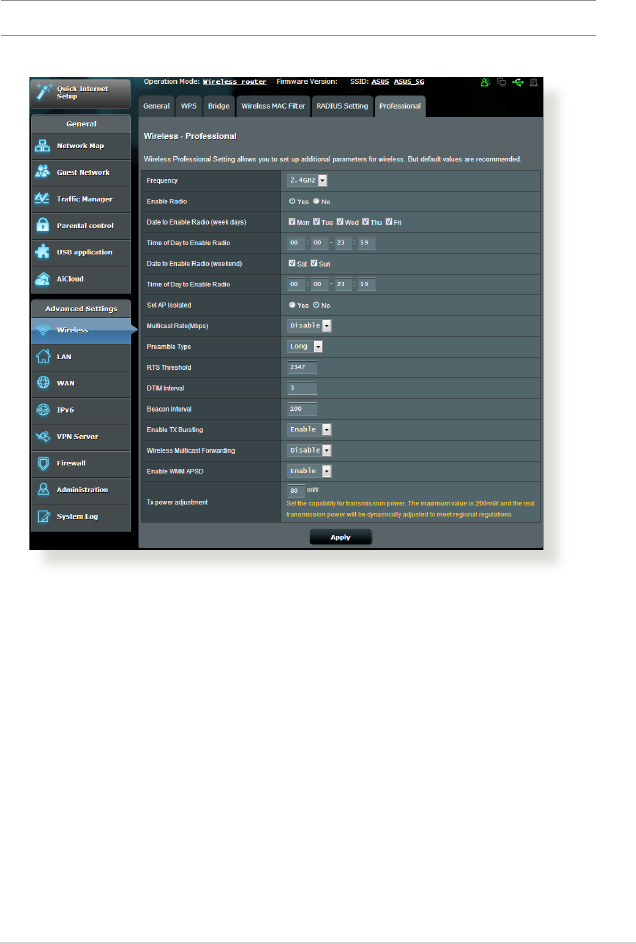
In the Professional Settings screen, you can congure the
following:
• Frequency: Select the frequency band that the professional
settings will be applied to.
• Enable Radio: Select Yes to enable wireless networking.
Select No to disable wireless networking.
• Date to Enable Radio (weekdays): You can specify which
days of the week wireless networking is enabled.
• Time of Day to Enable Radio: You can specify a time range
when wireless networking is enabled during the week.
4.1.6 Professional
The Professional screen provides advanced conguration options.
NOTE: We recommend that you use the default values on this page.

58
• Date to Enable Radio (weekend): You can specify which
days of the weekend wireless networking is enabled.
• Time of Day to Enable Radio: You can specify a time range
when wireless networking is enabled during the weekend.
• Set AP isolated: The Set AP isolated item prevents wireless
devices on your network from communicating with each
other. This feature is useful if many guests frequently join or
leave your network. Select Yes to enable this feature or select
No to disable.
• Multicast rate (Mbps): Select the multicast transmission
rate or click Disable to switch o simultaneous single
transmission.
• Preamble Type: Preamble Type denes the length of time
that the router spent for CRC (Cyclic Redundancy Check). CRC
is a method of detecting errors during data transmission.
Select Short for a busy wireless network with high network
trac. Select Long if your wireless network is composed of
older or legacy wireless devices.
• RTS Threshold: Select a lower value for RTS (Request to
Send) Threshold to improve wireless communication in a
busy or noisy wireless network with high network trac and
numerous wireless devices.
• DTIM Interval: DTIM (Delivery Trac Indication Message)
Interval or Data Beacon Rate is the time interval before a
signal is sent to a wireless device in sleep mode indicating
that a data packet is awaiting delivery. The default value is
three milliseconds.
• Beacon Interval: Beacon Interval is the time between one
DTIM and the next. The default value is 100 milliseconds.
Lower the Beacon Interval value for an unstable wireless
connection or for roaming devices.
• Enable TX Bursting: Enable TX Bursting improves
transmission speed between the wireless router and 802.11g
devices.
59
• Wireless multicast forwarding: Select Enable to allow the
wireless router to forward multicast trac to other wireless
devices that support multicast. Select Disable to prevent the
router from forwarding multicast transmissions.
• Enable WMM APSD: Enable WMM APSD (Wi-Fi Multimedia
Automatic Power Save Delivery) to improve power
management between wireless devices. Select Disable to
switch o WMM APSD.
• TX Power adjustment: TX Power adjustment refers to the
milliWatts (mW) needed to power the radio signal output of
the wireless router. Enter a value between 0 to 100.
NOTE: Increasing the TX Power adjustment values may aect the
stability of the wireless network.
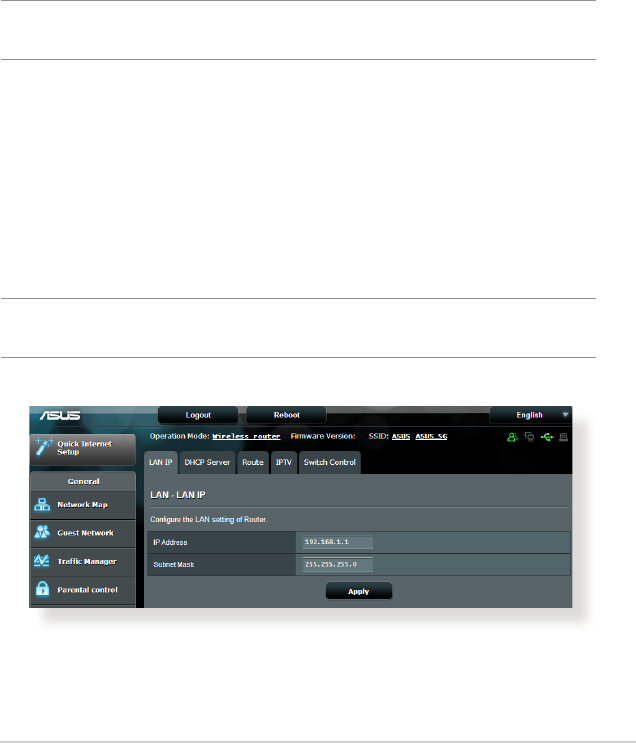
4.2 LAN
4.2.1 LAN IP
The LAN IP screen allows you to modify the LAN IP settings of your
wireless router.
NOTE: Any changes to the LAN IP address will be reected on your
DHCP settings.
60
To modify the LAN IP settings:
1. From the navigation panel, go to Advanced Settings > LAN >
LAN IP tab.
2. Modify the IP address and Subnet Mask.
3. When done, click Apply.
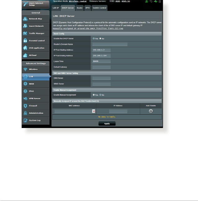
4.2.2 DHCP Server
Your wireless router uses DHCP to assign IP addresses
automatically on your network. You can specify the IP address
range and lease time for the clients on your network.
To congure the DHCP server:
1. From the navigation panel, go to Advanced Settings > LAN >
DHCP Server tab.
2. In the Enable the DHCP Server eld, tick Yes.

61
3. In the Domain Name text box, enter a domain name for the
wireless router.
4. In the IP Pool Starting Address eld, key in the starting IP
address.
5. In the IP Pool Ending Address eld, key in the ending IP
address.
6. In the Lease Time eld, specify in seconds when an assigned
IP address will expire. Once it reaches this time limit, the DHCP
server will then assign a new IP address.
NOTES:
• We recommend that you use an IP address format of 192.168.1.xxx
(where xxx can be any number between 2 and 254) when specifying
an IP address range.
• An IP Pool Starting Address should not be greater than the IP Pool
Ending Address.
7. In the DNS and Server Settings section, key in your DNS
Server and WINS Server IP address if needed.
8. Your wireless router can also manually assign IP addresses to
devices on the network. On the Enable Manual Assignment
eld, choose Yes to assign an IP address to specic MAC
addresses on the network. Up to 32 MAC Addresses can be
added to the DHCP list for manual assignment.
62
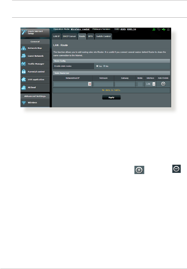
4.2.3 Route
If your network makes use of more than one wireless router, you
can congure a routing table to share the same Internet service.
NOTE: We recommend that you do not change the default route
settings unless you have advanced knowledge of routing tables.
To congure the LAN Routing table:
1. From the navigation panel, go to Advanced Settings > LAN >
Route tab.
2. On the Enable static routes eld, choose Yes.
3. On the Static Route List, enter the network information of
other access points or nodes. Click the Add or Delete
button to add or remove a device on the list.
4. Click Apply.
63
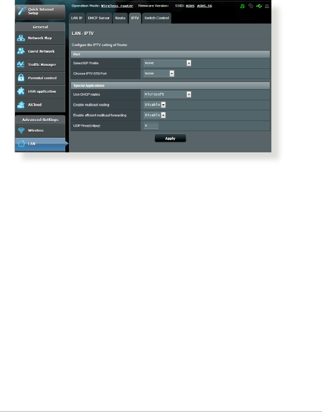
4.2.4 IPTV
The wireless router supports connection to IPTV services through
an ISP or a LAN. The IPTV tab provides the conguration settings
needed to set up IPTV, VoIP, multicasting, and UDP for your
service. Contact your ISP for specic information regarding your
service.
64
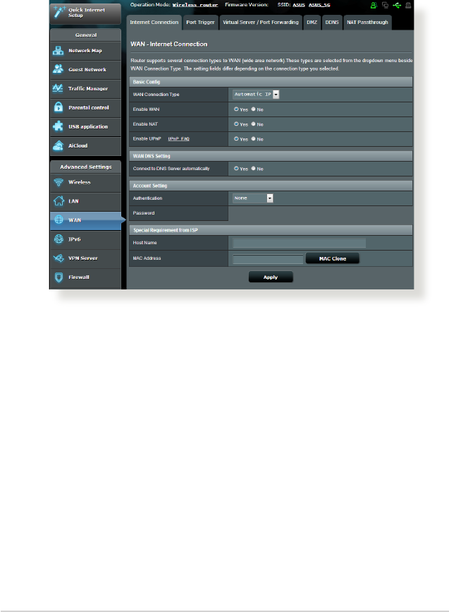
4.3 WAN
4.3.1 Internet Connection
The Internet Connection screen allows you to congure the
settings of various WAN connection types.
To congure the WAN connection settings:
1. From the navigation panel, go to Advanced Settings > WAN >
Internet Connection tab.
2. Congure the following settings below. When done, click
Apply.
WAN Connection Type: Choose your Internet Service Provider
type. The choices are Automatic IP, PPPoE, PPTP, L2TP or
xed IP. Consult your ISP if the router is unable to obtain a
valid IP address or if you are unsure the WAN connection type.
Enable WAN: Select Yes to allow the router Internet access.
Select No to disable Internet access.
•
•

65
Enable NAT: NAT (Network Address Translation) is a system
where one public IP (WAN IP) is used to provide Internet
access to network clients with a private IP address in a LAN.
The private IP address of each network client is saved in a NAT
table and is used to route incoming data packets.
Enable UPnP: UPnP (Universal Plug and Play) allows several
devices (such as routers, televisions, stereo systems, game
consoles, and cellular phone), to be controlled via an IP-based
network with or without a central control through a gateway.
UPnP connects PCs of all form factors, providing a seamless
network for remote conguration and data transfer. Using
UPnP, a new network device is discovered automatically.
Once connected to the network, devices can be remotely
congured to support P2P applications, interactive gaming,
video conferencing, and web or proxy servers. Unlike Port
forwarding, which involves manually conguring port
settings, UPnP automatically congures the router to accept
incoming connections and direct requests to a specic PC on
the local network.
Connect to DNS Server: Allows this router to get the DNS
IP address from the ISP automatically. A DNS is a host on
the Internet that translates Internet names to numeric IP
addresses.
Authentication: This item may be specied by some ISPs.
Check with your ISP and ll them in if required.
Host Name: This eld allows you to provide a host name for
your router. It is usually a special requirement from your ISP.
If your ISP assigned a host name to your computer, enter the
host name here.
•
•
•
•
•

66
MAC Address: MAC (Media Access Control) address is a
unique identier for your networking device. Some ISPs
monitor the MAC address of networking devices that connect
to their service and reject any unrecognized device that
attempt to connect. To avoid connection issues due to an
unregistered MAC address, you can:
• Contact your ISP and update the MAC address associated
with your ISP service.
• Clone or change the MAC address of the ASUS wireless router
to match the MAC address of the previous networking device
recognized by the ISP.
•
67
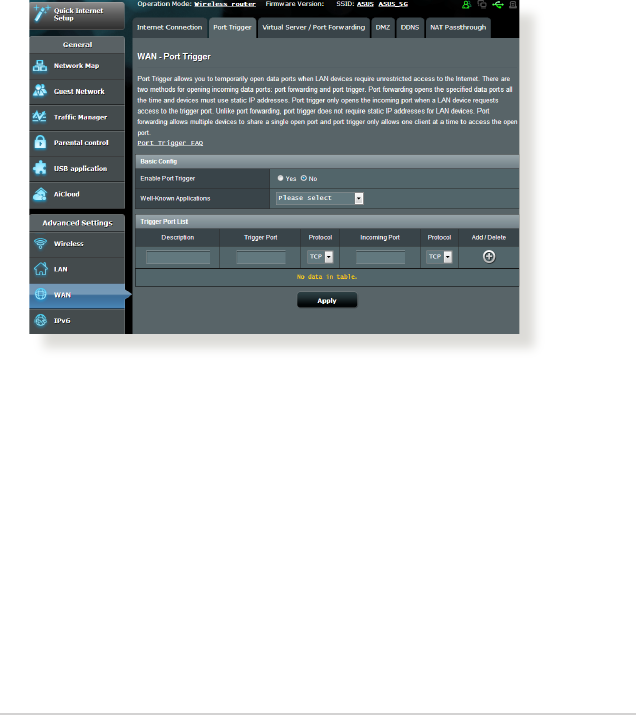
4.3.2 Port Trigger
Port range triggering opens a predetermined incoming port for a
limited period of time whenever a client on the local area network
makes an outgoing connection to a specied port. Port triggering
is used in the following scenarios:
More than one local client needs port forwarding for the
same application at a dierent time.
An application requires specic incoming ports that are
dierent from the outgoing ports.
•
•
To set up Port Trigger:
1. From the navigation panel, go to Advanced Settings > WAN >
Port Trigger tab.
2. Congure the following settings below. When done, click
Apply.
Enable Port Trigger: Choose Yes to enable Port Trigger.
Well-Known Applications: Select popular games and web
services to add to the Port Trigger List.
Description: Enter a short name or description for the service.
•
•
•

68
Trigger Port: Specify a trigger port to open the incoming port.
Protocol: Select the protocol, TCP, or UDP.
Incoming Port: Specify an incoming port to receive inbound
data from the Internet.
Protocol: Select the protocol, TCP, or UDP.
NOTES:
• When connecting to an IRC server, a client PC makes an outgoing
connection using the trigger port range 66660-7000. The IRC server
responds by verifying the username and creating a new connection
to the client PC using an incoming port.
• If Port Trigger is disabled, the router drops the connection because
it is unable to determine which PC is requesting for IRC access.
When Port Trigger is enabled, the router assigns an incoming port to
receive the inbound data. This incoming port closes once a specic
time period has elapsed because the router is unsure when the
application has been terminated.
• Port triggering only allows one client in the network to use a
particular service and a specic incoming port at the same time.
• You cannot use the same application to trigger a port in more than
one PC at the same time. The router will only forward the port back
to the last computer to send the router a request/trigger.
•
•
•
•
69
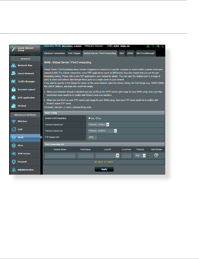
4.3.3 Virtual Server/Port Forwarding
Port forwarding is a method to direct network trac from the
Internet to a specic port or a specic range of ports to a device
or number of devices on your local network. Setting up Port
Forwarding on your router allows PCs outside the network to
access specic services provided by a PC in your network.
NOTE: When port forwarding is enabled, the ASUS router blocks
unsolicited inbound trac from the Internet and only allows replies
from outbound requests from the LAN. The network client does not
have access to the Internet directly, and vice versa.
To set up Port Forwarding:
1. From the navigation panel, go to Advanced Settings > WAN >
Virtual Server / Port Forwarding tab.

70
2. Congure the following settings below. When done, click
Apply.
Enable Port Forwarding: Choose Yes to enable Port
Forwarding.
Famous Server List: Determine which type of service you
want to access.
Famous Game List: This item lists ports required for popular
online games to work correctly.
FTP Server Port: Avoid assigning the port range 20:21 for
your FTP server as this would conict with the router’s native
FTP server assignment.
Service Name: Enter a service name.
Port Range: If you want to specify a Port Range for clients
on the same network, enter the Service Name, the Port
Range (e.g. 10200:10300), the LAN IP address, and leave the
Local Port empty. Port range accepts various formats such
as Port Range (300:350), individual ports (566,789) or Mix
(1015:1024,3021).
NOTES:
• When your network’s rewall is disabled and you set 80 as the HTTP
server’s port range for your WAN setup, then your http server/web
server would be in conict with the router’s web user interface.
• A network makes use of ports in order to exchange data, with each
port assigned a port number and a specic task. For example, port 80
is used for HTTP. A specic port can only be used by one application
or service at a time. Hence, two PCs attempting to access data
through the same port at the same time would fail. For example, you
cannot set up Port Forwarding for port 100 for two PCs at the same
time.
•
•
•
•
•
•

71
Local IP: Key in the client’s LAN IP address.
NOTE: Use a static IP address for the local client to make port forwarding
work properly. Refer to section 4.2 LAN for information.
Local Port: Enter a specic port to receive forwarded packets.
Leave this eld blank if you want the incoming packets to be
redirected to the specied port range.
Protocol: Select the protocol. If you are unsure, select BOTH.
To check if Port Forwarding has been congured successfully:
Ensure that your server or application is set up and running.
You will need a client outside your LAN but has Internet
access (referred to as “Internet client”). This client should not
be connected to the ASUS router.
On the Internet client, use the router’s WAN IP to access the
server. If port forwarding has been successful, you should be
able to access the les or applications.
Dierences between port trigger and port forwarding:
Port triggering will work even without setting up a specic
LAN IP address. Unlike port forwarding, which requires a
static LAN IP address, port triggering allows dynamic port
forwarding using the router. Predetermined port ranges are
congured to accept incoming connections for a limited
period of time. Port triggering allows multiple computers
to run applications that would normally require manually
forwarding the same ports to each PC on the network.
Port triggering is more secure than port forwarding since the
incoming ports are not open all the time. They are opened
only when an application is making an outgoing connection
through the trigger port.
•
•
•
•
•
•
•
•

72
4.3.4 DMZ
Virtual DMZ exposes one client to the Internet, allowing this
client to receive all inbound packets directed to your Local Area
Network.
Inbound trac from the Internet is usually discarded and routed
to a specic client only if port forwarding or a port trigger has
been congured on the network. In a DMZ conguration, one
network client receives all inbound packets.
Setting up DMZ on a network is useful when you need incoming
ports open or you want to host a domain, web, or e-mail server.
Caution: Opening all the ports on a client to the Internet makes the
network vulnerable to outside attacks. Please be aware of the security
risks involved in using DMZ.
To set up DMZ:
1. From the navigation panel, go to Advanced Settings > WAN >
DMZ tab.
2. Congure the setting below. When done, click Apply.
IP address of Exposed Station: Key in the client’s LAN IP
address that will provide the DMZ service and be exposed
on the Internet. Ensure that the server client has a static IP
address.
To remove DMZ:
1. Delete the client’s LAN IP address from the IP Address of
Exposed Station text box.
2. When done, click Apply.
•
73
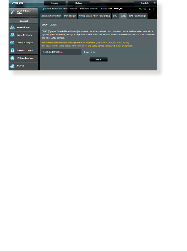
4.3.5 DDNS
Setting up DDNS (Dynamic DNS) allows you to access the router
from outside your network through the provided ASUS DDNS
Service or another DDNS service.
To set up DDNS:
1. From the navigation panel, go to Advanced Settings > WAN >
DDNS tab.
2. Congure the following settings below. When done, click
Apply.
Enable the DDNS Client: Enable DDNS to access the ASUS
router via the DNS name rather than WAN IP address.
Server and Host Name: Choose ASUS DDNS or other DDNS.
If you want to use ASUS DDNS, ll in the Host Name in the
format of xxx.asuscomm.com (xxx is your host name).
If you want to use a dierent DDNS service, click FREE TRIAL
and register online rst. Fill in the User Name or E-mail
Address and Password or DDNS Key elds.
•
•
•
74
Enable wildcard: Enable wildcard if your DDNS service
requires one.
NOTES:
DDNS service will not work under these conditions:
• When the wireless router is using a private WAN IP address (192.168.
x.x, 10.x.x.x, or 172.16.x.x), as indicated by a yellow text.
• The router may be on a network that uses multiple NAT tables.
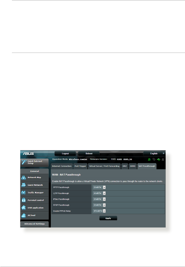
4.3.6 NAT Passthrough
NAT Passthrough allows a Virtual Private Network (VPN)
connection to pass through the router to the network clients.
PPTP Passthrough, L2TP Passthrough, IPsec Passthrough and RTSP
Passthrough are enabled by default.
To enable / disable the NAT Passthrough settings, go to the
Advanced Settings > WAN > NAT Passthrough tab. When done,
click Apply.
•
75
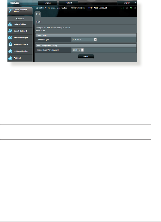
4.4 IPv6
This wireless router supports IPv6 addressing, a system that
supports more IP addresses. This standard is not yet widely
available. Contact your ISP if your Internet service supports IPv6.
To set up IPv6:
1. From the navigation panel, go to Advanced Settings > IPv6.
2. Select your Connection Type. The conguration options vary
depending on your selected connection type.
3. Enter your IPv6 LAN and DNS settings.
4. Click Apply.
NOTE: Please refer to your ISP regarding specic IPv6 information for
your Internet service.
76
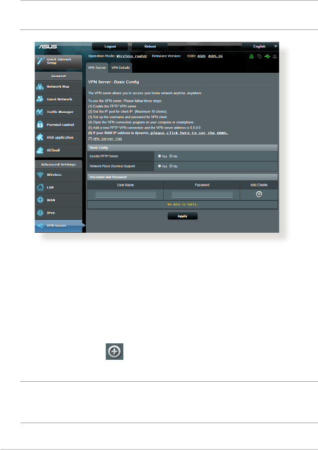
4.5 VPN Server
VPN (Virtual Private Network) provides a secure communication
to a remote computer or remote network using a public network
such as the Internet.
NOTE: Before setting up a VPN connection, you would need the IP
address or domain name of the VPN server you are trying to access.
To set up access to a VPN server:
1. From the navigation panel, go to Advanced Settings > VPN
Server.
2. On the Enable PPTP Server eld, select Yes.
3. On the Network Place (Samba) Support eld, select Yes.
4. Enter the user name and password for accessing the VPN
server. Click the button.
5. Click Apply.
NOTE: For advanced VPN server settings, click the VPN Server tab to
congure broadcast support, authentication, MPPE Encryption, and
Client IP address range.

77
4.6 Firewall
The wireless router can serve as a hardware rewall for your
network.
NOTE: The Firewall feature is enabled by default.
4.6.1 General
To set up basic Firewall settings:
1. From the navigation panel, go to Advanced Settings >
Firewall > General tab.
2. On the Enable Firewall eld, select Yes.
3. On the Enable DoS protection, select Yes to protect your
network from DoS (Denial of Service) attacks though this may
aect your router’s performance.
4. You can also monitor packets exchanged between the LAN
and WAN connection. On the Logged packets type, select
Dropped, Accepted, or Both.
5. Click Apply.
4.6.2 URL Filter
You can specify keywords or web addresses to prevent access to
specic URLs.
NOTE: The URL Filter is based on a DNS query. If a network client has
already accessed a website such as http://www.abcxxx.com, then the
website will not be blocked (a DNS cache in the system stores previously
visited websites). To resolve this issue, clear the DNS cache before
setting up the URL Filter.
78
To set up a URL lter:
1. From the navigation panel, go to Advanced Settings >
Firewall > URL Filter tab.
2. On the Enable URL Filter eld, select Enabled.
3. Enter a URL and click the button.
4. Click Apply.
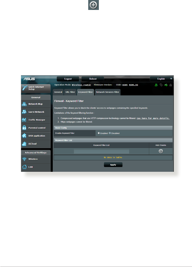
4.6.3 Keyword lter
Keyword lter blocks access to webpages containing specied
keywords.
To set up a keyword lter:
1. From the navigation panel, go to Advanced Settings >
Firewall > Keyword Filter tab.
2. On the Enable Keyword Filter eld, select Enabled.
79
3. Enter a word or phrase and click the Add button.
4. Click Apply.
NOTES:
• The Keyword Filter is based on a DNS query. If a network client has
already accessed a website such as http://www.abcxxx.com, then
the website will not be blocked (a DNS cache in the system stores
previously visited websites). To resolve this issue, clear the DNS cache
before setting up the Keyword Filter.
• Web pages compressed using HTTP compression cannot be ltered.
HTTPS pages also cannot be blocked using a keyword lter.
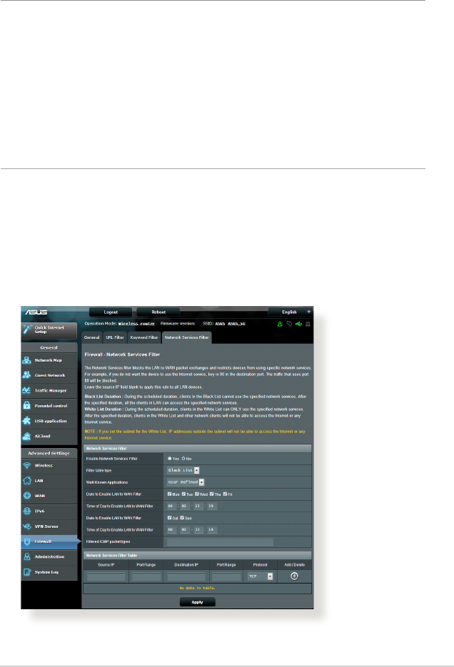
4.6.4 Network Services Filter
The Network Services Filter blocks LAN to WAN packet exchanges
and restricts network clients from accessing specic web services
such as Telnet or FTP.

80
To set up a Network Service lter:
1. From the navigation panel, go to Advanced Settings >
Firewall > Network Service Filter tab.
2. On the Enable Network Services Filter eld, select Yes.
3. Select the Filter table type. Black List blocks the specied
network services. White List limits access to only the specied
network services.
4. Specify the day and time when the lters will be active.
5. To specify a Network Service to lter, enter the Source IP,
Destination IP, Port Range, and Protocol. Click the button.
6. Click Apply.
81
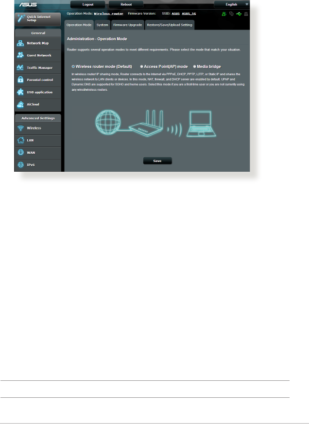
4.7 Administration
4.7.1 Operation Mode
The Operation Mode page allows you to select the appropriate
mode for your network.
To set up the operating mode:
1. From the navigation panel, go to Advanced Settings >
Administration > Operation Mode tab.
2. Select any of these operation modes:
• Wireless router mode (default): In wireless router mode,
the wireless router connects to the Internet and provides
Internet access to available devices on its own local network.
• Media Bridge: This setup requires two wireless routers.
The second router serves as a media bridge where multiple
devices such as Smart TVs and gaming consoles can be
connected via ethernet.
• Access Point mode: In this mode, the router creates a new
wireless network on an exising network.
3. Click Apply.
NOTE: The router will reboot when you change the modes.

82
4.7.2 System
The System page allows you to congure your wireless router
settings.
To set up the System settings:
1. From the navigation panel, go to Advanced Settings >
Administration > System tab.
2. You can congure the following settings:
• Change router login password: You can change the
password and login name for the wireless router by entering
a new name and password.
• WPS button behavior: The physical WPS button on the
wireless router can be used to activate WPS or switch o
wireless networking.
• Time Zone: Select the time zone for your network.
• NTP Server: The wireless router can access a NTP (Network
time Protocol) server in order to synchronize the time.
• Enable Telnet: Click Yes to enable Telnet services on the
network. Click No to disable Telnet.
• Authentication Method: You can select HTTP, HTTPS, or
both protocols to secure router access.
• Enable Web Access from WAN: Select Yes to allow devices
outside the network to access the wireless router GUI
settings. Select No to to prevent access.
• Only allow specic IP: Click Yes if you want to specify the IP
addresses of devices that are allowed access to the wireless
router GUI settings from WAN.
• Client List: Enter the WAN IP addresses of networking
devices allowed to access the wireless router settings. This
list will be used if you clicked Yes in the Only allow specic
IP item.
3. Click Apply.

83
4.7.3 Firmware Upgrade
NOTE: Download the latest rmware from the ASUS website at
http://www.asus.com
To upgrade the rmware:
1. From the navigation panel, go to Advanced Settings >
Administration > Firmware Upgrade tab.
2. In the New Firmware File eld, click Browse to locate the
downloaded le.
3. Click Upload.
NOTES:
• When the upgrade process is complete, wait for some time for the
system to reboot.
• If the upgrade process fails, the wireless router automatically enters
rescue mode and the power LED indicator on the front panel starts
ashing slowly. To recover or restore the system, refer to section 5.2
Firmware Restoration.
4.7.4 Restore/Save/Upload Setting
To restore/save/upload wireless router settings:
1. From the navigation panel, go to Advanced Settings >
Administration > Restore/Save/Upload Setting tab.
2. Select the tasks that you want to do:
• To restore to the default factory settings, click Restore, and
click OK in the conrmation message.
• To save the current system settings, click Save, navigate to
the folder where you intend to save the le and click Save.
• To restore from a saved system settings le, click Browse to
locate your le, then click Upload.
If issues occur, upload the latest rmware version and congure new
settings. Do not restore the router to its default settings.
84
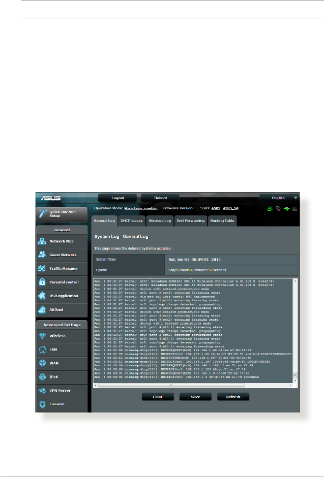
4.8 System Log
System Log contains your recorded network activities.
NOTE: System log resets when the router is rebooted or powered o.
To view your system log:
1. From the navigation panel, go to Advanced Settings > System
Log.
2. You can view your network activities in any of these tabs:
• General Log
• DHCP Leases
• Wireless Log
• Port Forwarding
• Routing Table