ASUSTeK Computer UX30INTEL512H NOTEBOOK P.C. User Manual UX30 ENGLISH
ASUSTeK Computer Inc NOTEBOOK P.C. UX30 ENGLISH
UserManual.wiki
>
ASUSTeK Computer
>
UX30INTEL512H User Manual
Users Manual
Navigation menu
Upload a User Manual
Namespaces
Wiki Guide
HTML
PDF
Info
Views
User Manual
Discussion / Help
Navigation

![6About This Userʼs ManualYou are reading the Notebook PC Userʼs Manual. This Userʼs Manual provides information on the various components in the Notebook PC and how to use them. The following are major sections of this Userʼs Manuals:1. Introducing the Notebook PC Introduces you to the Notebook PC and this Userʼs Manual.2. Knowing the Parts Gives you information on the Notebook PCʼs components.3. Getting Started Gives you information on getting started with the Notebook PC.4. Using the Notebook PC Gives you information on using the Notebook PCʼs components.5. Appendix Introduces you to optional accessories and gives additional information. Notes For This ManualA few notes and warnings in bold are used throughout this guide that you should be aware of in order to complete certain tasks safely and completely. These notes have different degrees of importance as described below:NOTE: Tips and information for special situations.TIP: Tips and useful information for completing tasks.IMPORTANT! Vital information that must be followed to prevent damage to data, components, or persons.WARNING! Important information that must be followed for safe operation.Text enclosed in < > or [ ] represents a key on the keyboard; do not actually type the < > or [ ] and the enclosed letters. < >[ ]1 Introducing the Notebook PC](https://usermanual.wiki/ASUSTeK-Computer/UX30INTEL512H/User-Guide-1135664-Page-6.png)

![23IMPORTANT! If warnings are still given during bootup after running a software disk checking utility, you should take your Notebook PC in for servicing. Continued use may result in data loss. IMPORTANT! To protect the hard disk drive, always wait at least 5 seconds after turning OFF your Notebook PC before turning it back ON. WARNING! DO NOT carry or cover a Notebook PC that is powered ON with any ma-terials that will reduce air circulation such as a carrying bag.Before bootup, the display panel flashes when the power is turned ON. This is part of the Notebook PCʼs test routine and is not a problem with the display.Powering ON the Notebook PCThe Notebook PCʼs power-ON message appears on the screen when you turn it ON. If necessary, you may adjust the brightness by using the hot keys. If you need to run the BIOS Setup to set or modify the system configuration, press [F2] upon bootup to enter the BIOS Setup. If you press [Tab] during the splash screen, standard boot information such as the BIOS version can be seen. Press [ESC] and you will be presented with a boot menu with selections to boot from your available drives.The Power-On Self Test (POST)When you turn ON the Notebook PC, it will first run through a series of software-controlled diag-nostic tests called the Power-On Self Test (POST). The software that controls the POST is installed as a permanent part of the Notebook PCʼs architecture. The POST includes a record of the Notebook PCʼs hardware configuration, which is used to make a diagnostic check of the system. This record is created by using the BIOS Setup program. If the POST discovers a difference between the record and the existing hardware, it will display a message on the screen prompting you to correct the conflict by running BIOS Setup. In most cases the record should be correct when you receive the Notebook PC. When the test is finished, you may get a message reporting “No operating system found” if the hard disk was not preloaded with an operating system. This indicates that the hard disk is correctly detected and ready for the installation of a new operating system.Self Monitoring and Reporting TechnologyThe S.M.A.R.T. (Self Monitoring and Reporting Technology) checks the hard disk drive during POST and gives a warning message if the hard disk drive re-quires servicing. If any critical hard disk drive warning is given during bootup, backup your data immediately and run Windows disk checking program. To run Windowʼs disk checking program: click Start > select Computer > right-click a hard disk drive icon > choose Properties > click the Tools tab > click Check Now > click Start. You can also select “Scan ... sectors” for more effective scan and repair but the process will run slower. Getting Started 3](https://usermanual.wiki/ASUSTeK-Computer/UX30INTEL512H/User-Guide-1135664-Page-23.png)
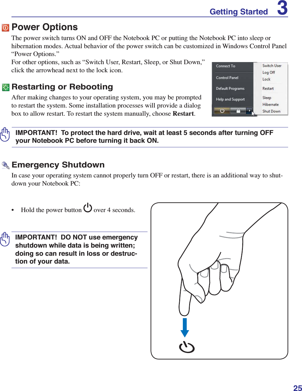
![26Thermal Power ControlThere are three power control methods for controlling the Notebook PCʼs thermal state. These power control cannot be configured by the user and should be known in case the Notebook PC should enter these states. The following temperatures represent the chassis temperature (not CPU).• The fan turns ON for active cooling when the temperature reaches the safe upper limit.• The CPU decreases speed for passive cooling when the temperature exceeds the safe upper limit.• The system shut down for critical cooling when temperature exceeds the maximum safe upper limit.Sleep and HibernatePower management settings can be found in the Windows > Control Panel > Power Options. In System Settings, you can define “Sleep/Hibernate” or “Shut Down” for closing the display panel or pressing the power button. “Sleep” and “Hibernate” saves power when your Notebook PC is not in use by turning OFF certain components. When you resume your work, your last status (such as a document scrolled down half way or email typed half way) will reappear as if you never left. “Shut Down” will close all applications and ask if you want to save your work if any are not saved.Hibernate is the same as Suspend-to-Disk (STD) and stores your current data and status on the hard disk drive. By doing this, RAM does not have to be periodically refreshed and power consumption is greatly reduced but not completely eliminated because certain wake-up components like LAN needs to remain powered. “Hibernate” saves more power compared to “Sleep”. Click the Start button and the arrowhead next to the lock icon to see this option. Recover by pressing the power button. (NOTE: The power indicator will be OFF in this mode.)Sleep is the same as Suspend-to-RAM (STR). This function stores your current data and status in RAM while many components are turned OFF. Because RAM is volatile, it requires power to keep (refresh) the data. Click the Start button and the arrowhead next to the lock icon to see this option. You can also use the keyboard shortcut [Fn F1] to activate this mode. Recover by pressing any keyboard key except [Fn]. (NOTE: The power indicator will blink in this mode.)Power Management ModesThe Notebook PC has a number of automatic or adjustable power saving features that you can use to maximize battery life and lower Total Cost of Ownership (TCO). You can control some of these fea-tures through the Power menu in the BIOS Setup. ACPI power management settings are made through the operating system. The power management features are designed to save as much electricity as pos-sible by putting components into a low power consumption mode as often as possible but also allow full operation on demand.3 Getting Started](https://usermanual.wiki/ASUSTeK-Computer/UX30INTEL512H/User-Guide-1135664-Page-26.png)
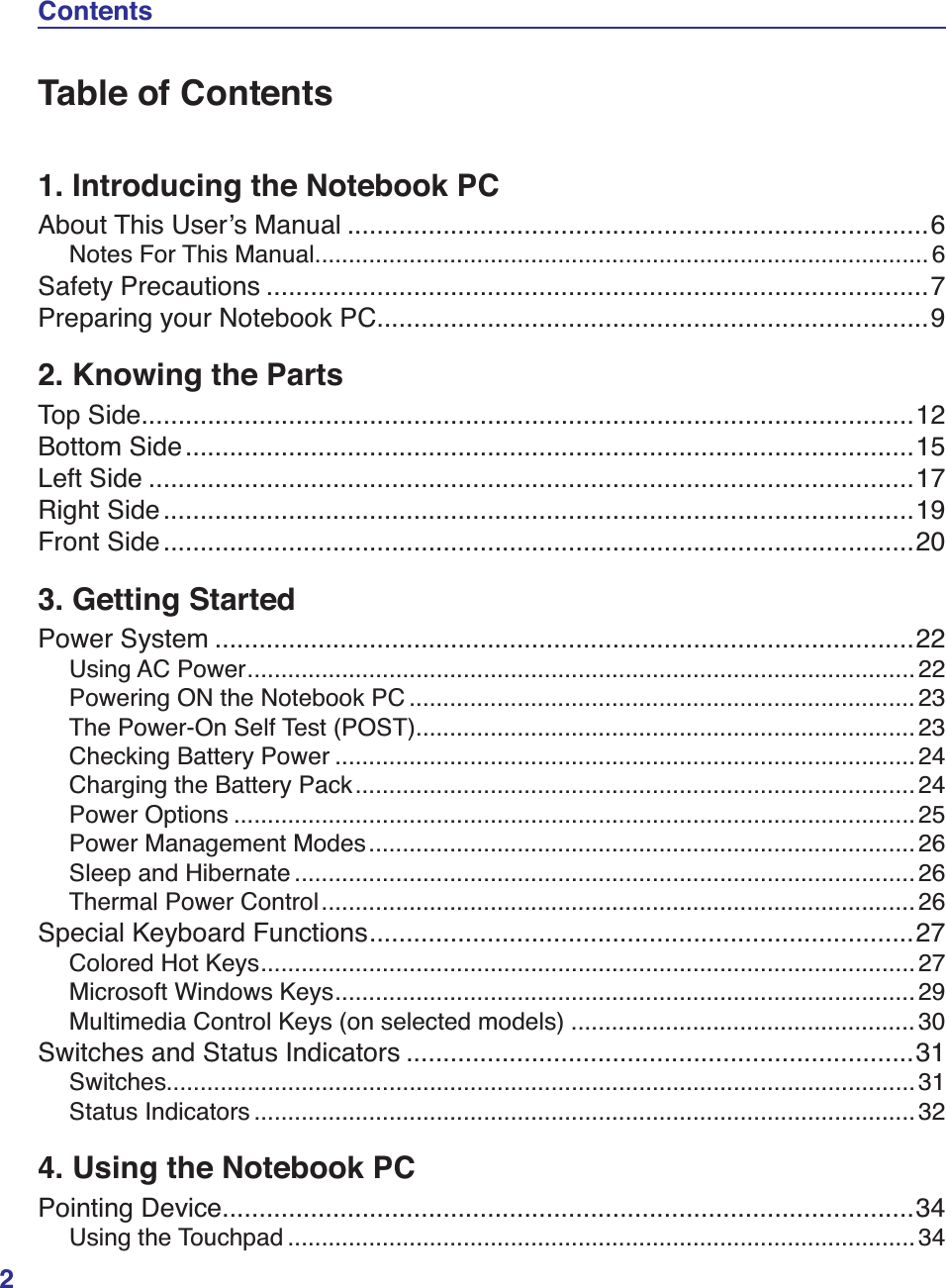
![29Microsoft Windows KeysGetting Started 3The other key, that looks like a Windows menu with a small pointer, activates the properties menu and is equivalent to pressing the right mouse button on a Windows object. There are two special Windows keys on the keyboard as described below.The key with the Windows Logo activates the Start menu located at the bottom left of the Windows desktop.The red arrows are illustrated here for your reference. They are not labeled on the keyboard as shown here.Keyboard as a Numeric Keypad The numeric keypad is embedded in the keyboard and consists of 15 keys that make number intensive input more convenient. These dual-purpose keys are labeled in orange on the key caps. Numeric assignments are located at the upper right hand corner of each key as shown in the figure. When the numeric keypad is engaged by pressing [Fn][Ins/Num LK], the number lock LED lights up. If an external keyboard is connected, pressing the [Ins/Num LK] on the external keyboard enables/disa-bles the NumLock on both keyboards simultaneously. To disable the numeric keypad while keeping the keypad on an external keyboard activated, press the [Fn][Ins/Num LK] keys on the Notebook PC.Keyboard as PointersThe keyboard can be used as pointers while Number Lock is ON or OFF in order to increase navigation ease while entering numeric data in spreadsheets or similar applications.With Number Lock OFF, press [Fn] and one of the pointer keys shown below. For example [Fn][8] for up, [Fn][K] for down, [Fn][U] for left, and [Fn][O] for right. With Number Lock ON, use [Shift] and one of the pointer keys shown below. For example [Shift][8] for up, [Shift][K] for down, [Shift][U] for left, and [Shift][O] for right.](https://usermanual.wiki/ASUSTeK-Computer/UX30INTEL512H/User-Guide-1135664-Page-29.png)
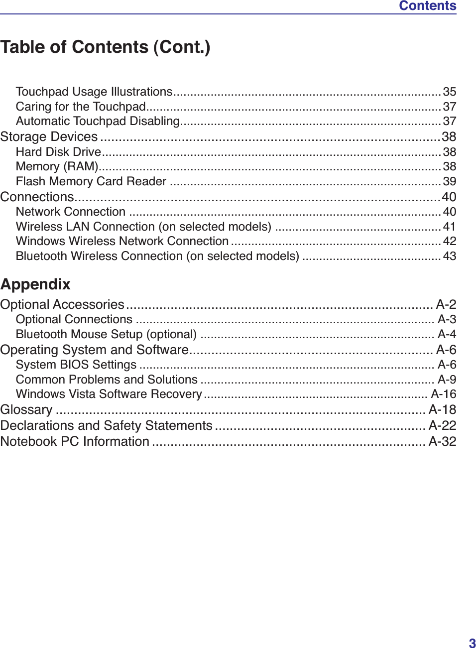
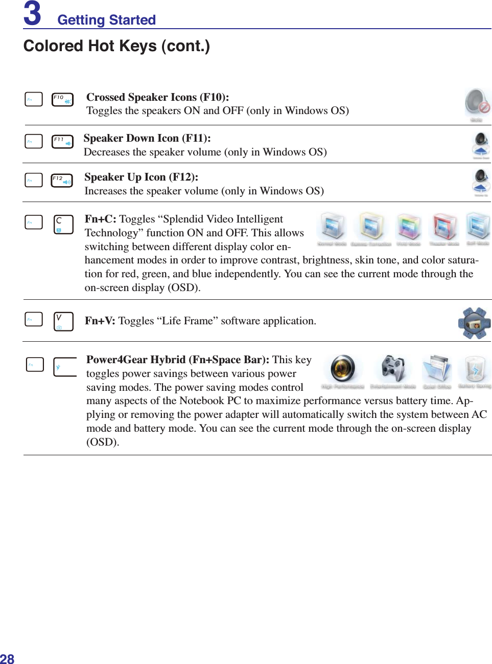
![30Multimedia Control Keys (on selected models)The multimedia control keys allows for convenient controlling of the multimedia application. The fol-lowing defines the meaning of each multimedia control key on the Notebook PC.Use the [Fn] key in combination with the arrow keys for CD control functions.Some control key functions may defer depending on Notebook PC model. 3 Getting StartedCD Play/PauseDuring CD stop, begins CD play.During CD play, pauses CD play.CD StopDuring CD play: Stops CD play.CD Skip to Next Track (Fast Forward)During CD play, skips to the next audio track/movie chapter.Audio Volume ControlsFn + Speaker Icons (F10): Toggles the audio volume ON and OFFFn + Down Speaker Icon (F11): Decreases the audio volumeFn + Up Speaker Icon (F12): Increases the audio volumeCD Skip to Previous Track (Rewind)During CD play, skips to the previous audio track/movie chapter.](https://usermanual.wiki/ASUSTeK-Computer/UX30INTEL512H/User-Guide-1135664-Page-30.png)
![32Status IndicatorsSwitches and Status Indicators (cont.)Battery Charge IndicatorThe battery charge indicator shows the status of the batteryʼs power as follows: ON: The Notebook PCʼs battery is charging when AC power is connected. OFF: The Notebook PCʼs battery is charged or completely drained. Blinking: Battery power is less than 10% and the AC power is not connected.Power IndicatorThe power indicator lights when the Notebook PC is turned ON and blinks slowly when the Notebook PC is in the Suspend-to-RAM (Sleep) mode. This indicator is OFF when the Note-book PC is turned OFF or in the Suspend-to-Disk (Hibernation) mode.Drive Activity IndicatorIndicates that the Notebook PC is accessing one or more storage device(s) such as the hard disk. The light flashes proportional to the access time.Capital Lock IndicatorIndicates that capital lock [Caps Lock] is activated when lighted. Capital lock allows some of the keyboard letters to type using capitalized letters (e.g. A, B, C). When the capital lock light is OFF, the typed letters will be in the lower case form (e.g. a,b,c). Bluetooth / Wireless IndicatorThis is only applicable on models with internal Bluetooth (BT) and built-in wireless LAN. This indicator will light to show that the Notebook PCʼs built-in Bluetooth (BT) function is activated. When the built-in wireless LAN is enabled, this indicator will also light. (Windows software settings are necessary.)3 Getting Started](https://usermanual.wiki/ASUSTeK-Computer/UX30INTEL512H/User-Guide-1135664-Page-32.png)
![422. Press [FN+F2] repeatedly until wireless LAN icon and bluetooth icon are shown.Windows Wireless Network ConnectionConnecting to a network4. Right click on the network icon and select Connect to a network.3. You should see the “Not Connected” network icon.5. Select “Show Wireless” if you have many networks in your area.6. Select the wireless network you want to connect to.7. When connecting, you may have to enter a password.8. After connection has been established, “Connected” will be shown.2b. Or double click the Wireless Console icon on Windows notification area and select the wireless LAN icon.1. Switch ON the Wireless function if necessary for your model (see switches in Section 3). 4 Using the Notebook PC](https://usermanual.wiki/ASUSTeK-Computer/UX30INTEL512H/User-Guide-1135664-Page-42.png)
![43Bluetooth Wireless Connection (on selected models)Notebook PCs with Bluetooth technology eliminates the need for cables for connecting Bluetooth-enabled devices. Examples of Bluetooth-enabled devices may be Notebook PCs, Desktop PCs, mobile phones, and PDAs. If your Notebook PC did not come with built-in Bluetooth, you need to connect a USB or ExpressCard Bluetooth module in order to use Bluetooth. Bluetooth-enabled mobile phonesYou can wireless connect to your mobile phone. Depending on your mobile phoneʼs capabilities, you can transfer phone book data, photos, sound files, etc. or use it as a modem to connect to the Internet. You may also use it for SMS messaging. Bluetooth-enabled computers or PDAsYou can wireless connect to another computer or PDA and exchange files, share peripherals, or share Internet or network connections. You may also make use of Bluetooth-enabled wireless keyboard or mouse.2b. Or double click the Wireless Console icon on the Windows notification area and select the bluetooth icon.3. Select Add a Bluetooth Device in the notification area menu.3b. Or Launch Bluetooth Devices from the Windows Control Panel.Turning ON and Launching Bluetooth UtilityThis process can be used to add most Bluetooth devices. See Appendix for complete process.1. Switch ON the Wireless function if necessary for your model (see switches in Section 3).2. Press [FN+F2] repeatedly until wireless LAN icon and bluetooth icon are shown.Using the Notebook PC 4](https://usermanual.wiki/ASUSTeK-Computer/UX30INTEL512H/User-Guide-1135664-Page-43.png)
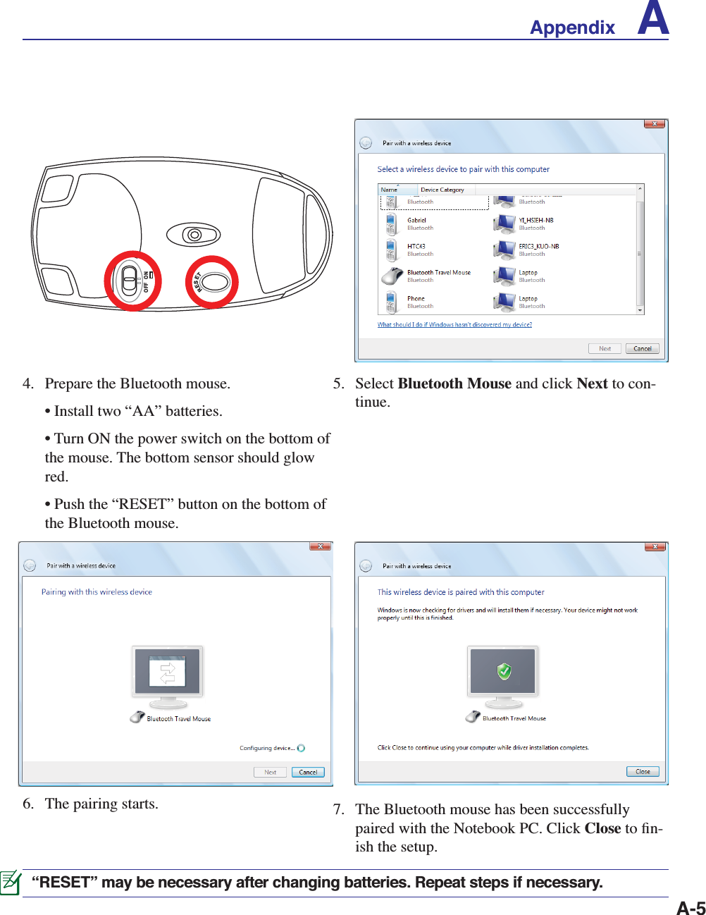
![A-4A AppendixBluetooth Mouse Setup (optional)This process can be used to add most Bluetooth devices in Windows operating system.3. Select Add a Bluetooth Device on the taskbar menu.3c. If launched from the Control Panel, click Add from this screen.1. Switch ON the Wireless function if necessary for your model (see switches in Section 3).3b. Or Launch Bluetooth Devices from the Win-dows Control Panel.2b. Or double click the Wireless Console icon on the Windows notification area and select the bluetooth icon.2. Press [FN+F2] repeatedly until wireless LAN icon and bluetooth icon are shown.](https://usermanual.wiki/ASUSTeK-Computer/UX30INTEL512H/User-Guide-1135664-Page-48.png)
![A-6A AppendixSupport SoftwareThis Notebook PC comes with a support disc that provides BIOS, drivers and applica-tions to enable hardware features, extend functionality, help manage your Notebook PC, or add functionality not provided by the native operating system. If updates or replacement of the support disc is necessary, contact your dealer for web sites to download individual software drivers and utilities. The support disc contains all drivers, utilities and software for all popular operating systems including those that have been pre-installed. The support disc does not include the operating system itself. The support disc is necessary even if your Notebook PC came pre-configured in order to provide additional software not included as part of the factory pre-install. A recovery disc is optional and includes an image of the original operating system installed on the hard drive at the factory. The recovery disc provides a comprehensive recovery solution that quickly restores the Notebook PCʼs operating system to its original working state provided that your hard disk drive is in good working order. Contact your retailer if you require such a solution.Some of the Notebook PCʼs components and features may not work until the device drivers and utilities are installed.Operating System and SoftwareThis Notebook PC may offer (depending on territory) its customers the choice of a pre-installed Microsoft Windows operating system. The choices and languages will depend on the territory. The levels of hardware and software support may vary depending on the installed operating system. The stability and compatibility of other operating systems cannot be guaranteed.System BIOS SettingsBoot Device1. On the Boot screen, select Boot Device Priority. Select Screen Select ItemEnter Go to Sub ScreenF1 General HelpF10 Save and ExitESC Exitv02.59 (C)Copyright 1985-2005, American Megatrends, Inc.BIOS SETUP UTILITYMain Advanced Security Power Boot ExitBoot Settings Boot Settings Configuration Boot Device Priority Hard Disk DrivesOnboard LAN Boot ROM [Disabled]Specifies the Boot Device Boot Priority sequence.A virtual floppy disk drive (Floppy Drive B: ) may appear when you set the CD-ROM drive as the first boot device.](https://usermanual.wiki/ASUSTeK-Computer/UX30INTEL512H/User-Guide-1135664-Page-50.png)
![A-7Appendix A2. Select each item and press [Enter] to select a device. Security SettingTo set the password: 1. On the Security screen, select Change Supervisor or Change User Password.2. Type in a password and press [Enter].3. Re-type to confirm the password and press [Enter].4. Password is then set. Select Screen Select Item+- Change OptionF1 General HelpF10 Save and ExitESC Exitv02.59 (C)Copyright 1985-2005, American Megatrends, Inc.BIOS SETUP UTILITY BootBoot Device Priority1st Boot Device [Hard Drive]2nd Boot Device [CD/DVD]3rd Boot Device [Removable Device]4th Boot Device [Network]Specifies the boot sequence from the availabe devices.A device enclosed in parenthesis has been disabled in the corresponding type menu. Select Screen Select ItemEnter ChangeF1 General HelpF10 Save and ExitESC Exitv02.59 (C)Copyright 1985-2005, American Megatrends, Inc.BIOS SETUP UTILITY SecuritySecurity SettingsSupervisor Password : Not InstalledUser Password : Not InstalledChange Supervisor PasswordChange User Password Hard Disk Security Setting I/O Interface SecurityInstall or Change the password.System BIOS Settings (cont.)To clear the password: 1. Leave the password field blank and press [Enter].2. Password is then cleared.](https://usermanual.wiki/ASUSTeK-Computer/UX30INTEL512H/User-Guide-1135664-Page-51.png)
![A-8System BIOS Settings (cont.)Password CheckSelect whether to ask for a password during bootup (Always) or only when entering the BIOS setup utility (Setup).Select the level of access to allow the “User Pass-word” to have in the BIOS setup utility.User Access LevelSave ChangesIf you want to keep your configuration settings, you must save changes before exiting the BIOS setup utility. If you want to restore default settings, choose Load Setup Defaults. You must then save changes to keep the manufacture default settings. Select Screen Select Item Enter ChangeF1 General HelpF10 Save and ExitESC Exitv02.59 (C)Copyright 1985-2005, American Megatrends, Inc.BIOS SETUP UTILITY SecuritySecurity SettingsSupervisor Password : InstalledUser Password : InstalledChange Supervisor PasswordUser Access Level [Full Access]Change User PasswordClear User PasswordPassword Check [Setup] Hard Disk Security Setting I/O Interface SecuritySetup: Check password while invoking setup.Always: Check password while invoking setup as well as on each boot.OptionsAlwaysSetup Select Screen Select Item Enter ChangeF1 General HelpF10 Save and ExitESC Exitv02.59 (C)Copyright 1985-2005, American Megatrends, Inc.BIOS SETUP UTILITY SecuritySecurity SettingsSupervisor Password : InstalledUser Password : InstalledChange Supervisor PasswordUser Access Level [Full Access]Change User PasswordClear User PasswordPassword Check [Setup] Hard Disk Security Setting I/O Interface SecuritySetup: Check password while invoking setup.Always: Check password while invoking setup as well as on each boot.OptionsNo AccessView OnlyLimitedFull Access Select Screen Select ItemEnter Go to Sub ScreenTab Select FieldF1 General HelpF10 Save and ExitESC Exitv02.59 (C)Copyright 1985-2005, American Megatrends, Inc.BIOS SETUP UTILITYMain Advanced Security Power Boot ExitExit OptionsSave Changes and Exit Discard Changes and ExitDiscard ChangesLoad User DefaultsLoad Manufacture DefaultsExit system setup after saving the changes.F10 key can be used for this operation.A Appendix](https://usermanual.wiki/ASUSTeK-Computer/UX30INTEL512H/User-Guide-1135664-Page-52.png)
![A-13Software Problem - BIOSUpdating the BIOS.1. Please verify the Notebook PCʼs exact model and download the latest BIOS file for your model from the ASUS website and save it in your flash disk drive.2. Connect your flash disk drive to the Notebook PC and power on the Notebook PC.3. Use the “Easy Flash” function on the Advanced page of the BIOS Setup Utility. Follow the in-structions shown.4. Locate the latest BIOS file and start updating (flashing) the BIOS. Select Screen Select Item+- Change FieldEnter Go to Sub ScreenF1 General HelpF10 Save and ExitESC Exitv02.61 (C)Copyright 1985-2006, American Megatrends, Inc.BIOS SETUP UTILITYMain Advanced Security Power Boot Exit Advanced Settings WARNING: Setting wrong values in below sections may cause system to malfunction. IDE ConfigurationStart Easy FlashASUS FancyStart [Disabled]Internal Pointing Device [Enabled]Internal Numeric Pad Lock [Enabled]Speaker Volume [4]Intel Virtualization TechIntel VT-d [Disabled] Over-Clock in POST [0%]DTS-based Thermal Management [Enabled]Press ENTER to run the utility to select and update BIOS. Press Hotkey F4 at POST to invoke the Utility. This utility doesn't support : 1. CDROM 2. USB HDD 3. Secondary HDD Start Easy Flash Utility? [OK] [Cancel]AsusTek BIOS ROM Easy Flash Utility V1.15Current ROM Update ROMA:B:C:D:Note<Up/Dn> to move ,<Enter> to determine ,<BSpace> to drive selectFLASH TYPE: MXIC MX25L8005PATH: A:\ PLATFORM: UX30 VER: 002.T22DATE: 03/24/09PLATFORM: UnknownVER: UnknownDATE: Unknown5. You must “Load Setup Defaults” on the Exit page after updating (flashing) the BIOS. Drive FileAppendix A](https://usermanual.wiki/ASUSTeK-Computer/UX30INTEL512H/User-Guide-1135664-Page-57.png)
![A-16Windows Vista Software RecoveryUsing Hard Disk Partition The Recovery Partition includes an image of the operating system, drivers, and utilities installed on your Notebook PC at the factory. The Recovery Partition provides a comprehensive recovery solution that quickly restores your Notebook PCʼs software to its original working state, provided that your hard disk drive is in good working order. Before using the Recovery Partition, copy your data files (such as Outlook PST files) to USB flash disks or to a network drive and make note of any customized configuration settings (such as network settings).About the Recovery PartitionThe Recovery Partition is a space reserved on your hard disk drive used to restore the operating sys-tem, drivers, and utilities installed on your Notebook PC at the factory.IMPORTANT! DO NOT delete the partition named “RECOVERY”. The Recovery Partition is created at the factory and cannot be restored by the user if de-leted. Take your Notebook PC to an authorized ASUS service center if you have problems with the recovery process.Using the Recovery Partition:1. Press [F9] during bootup (requires a Recovery Partition) 2. Press [Enter] to select Windows Setup [EMS Enabled]3. Read the “ASUS Preload Wizard” screen and click Next.4. Select a partition option and click Next. Partition options:Recover Windows to first partition only.This option will delete only the first partition, allowing you to keep other partitions, and create a new system partition as drive “C”.Recover Windows to entire HD.This option will delete all partitions from your hard disk drive and create a new system partition as drive “C”.Recover Windows to entire HD with 2 partition.This option will delete all partitions from your hard drive and create two new partitions “C” (60%) and “D” (40%).5. Follow the on-screen instructions to complete the recovery process. Please visit www.asus.com for updated drivers and utilities.A Appendix](https://usermanual.wiki/ASUSTeK-Computer/UX30INTEL512H/User-Guide-1135664-Page-60.png)
![A-26R&TTE Directive (1999/5/EC)The following items were completed and are considered relevant and sufficient for the R&TTE (Radio & Telecommunications Terminal Equipment) directive:• Essential requirements as in [Article 3]• Protection requirements for health and safety as in [Article 3.1a]• Testing for electric safety according to [EN 60950]• Protection requirements for electromagnetic compatibility in [Article 3.1b]• Testing for electromagnetic compatibility in [EN 301 489-1] & [EN 301]• Testing according to [489-17]• Effective use of the radio spectrum as in [Article 3.2]• Radio test suites according to [EN 300 328-2]FCC Radio Frequency (RF) Exposure Caution StatementThis equipment complies with FCC RF exposure limits set forth for an uncontrolled environment. To maintain compliance with FCC RF exposure compliance requirements, please follow operation instructions in the userʼs manual. This equipment is for operation within 5.15 GHz and 5.25GHz frequency ranges and is restricted to indoor environments only.FCC Caution: Any changes or modifications not expressly approved by the party responsible for compliance could void the userʼs authority to operate this equip-ment. “The manufacturer declares that this device is limited to Channels 1 through 11 in the 2.4GHz frequency by specified firmware controlled in the USA.”FCC RF Exposure Guidelines (Wireless Clients)This device has been tested for compliance with FCC RF Exposure (SAR) limits in typical portable configurations. In order to comply with SAR limits established in the ANSI C95.1 standards, it is recommended when using a wireless LAN adapter that the integrated antenna is positioned more than [20cm] from your body or nearby persons during extended periods of operation. If the antenna is posi-tioned less than [20cm] from the user, it is recommended that the user limit the exposure time.The user is cautioned that this device should be used only as specified within this manual to meet RF exposure requirements. Use of this device in a manner inconsis-tent with this manual could lead to excessive RF exposure conditions.CE Mark WarningThis is a Class B product, in a domestic environment, this product may cause radio interference, in which case the user may be required to take adequate measures.A AppendixMax. SAR Measurement (1g) 802.11b: 0.680 W/kg 802.11g: 0.080 W/kg 802.11a(5.2GHz): 0.356 W/kg 802.11a(5.8GHz): 1.360 W/kg](https://usermanual.wiki/ASUSTeK-Computer/UX30INTEL512H/User-Guide-1135664-Page-70.png)