ASUSTeK Computer WL500GD WIRELESS ROUTER User Manual e1697 WL500g gx b unlocked
ASUSTeK Computer Inc WIRELESS ROUTER e1697 WL500g gx b unlocked
Contents
- 1. USERS MANUAL 1
- 2. USERS MANUAL 2
- 3. USERS MANUAL 3
USERS MANUAL 1
WL500g / WL500g Deluxe Wireless Router
(For 802.11g/b Wireless Clients)
WL500b Wireless Router
(For 802.11b Wireless Clients)
User’s Manual

2 ASUS Wireless Router
No part of this manual, including the products and software described in it,
may be reproduced, transmitted, transcribed, stored in a retrieval system,
or translated into any language in any form or by any means, except
documentation kept by the purchaser for backup purposes, without the
express written permission of ASUSTeK COMPUTER INC. (“ASUS”).
ASUS PROVIDES THIS MANUAL “AS IS” WITHOUT WARRANTY
OF ANY KIND, EITHER EXPRESS OR IMPLIED, INCLUDING BUT
NOT LIMITED TO THE IMPLIED WARRANTIES OR CONDITIONS
OF MERCHANTABILITY OR FITNESS FOR A PARTICULAR
PURPOSE. IN NO EVENT SHALL ASUS, ITS DIRECTORS, OFFICERS,
EMPLOYEES OR AGENTS BE LIABLE FOR ANY INDIRECT,
SPECIAL, INCIDENTAL, OR CONSEQUENTIAL DAMAGES
(INCLUDING DAMAGES FOR LOSS OF PROFITS, LOSS OF
BUSINESS, LOSS OF USE OR DATA, INTERRUPTION OF BUSINESS
AND THE LIKE), EVEN IF ASUS HAS BEEN ADVISED OF THE
POSSIBILITY OF SUCH DAMAGES ARISING FROM ANY DEFECT
OR ERROR IN THIS MANUAL OR PRODUCT.
Product warranty or service will not be extended if: (1) the product is
repaired, modified or altered, unless such repair, modification of alteration
is authorized in writing by ASUS; or (2) the serial number of the product is
defaced or missing.
Products and corporate names appearing in this manual may or may not be
registered trademarks or copyrights of their respective companies, and are
used only for identification or explanation and to the owners’ benefit, without
intent to infringe.
SPECIFICATIONS AND INFORMATION CONTAINED IN THIS
MANUAL ARE FURNISHED FOR INFORMATIONAL USE ONLY, AND
ARE SUBJECT TO CHANGE AT ANY TIME WITHOUT NOTICE, AND
SHOULD NOT BE CONSTRUED AS A COMMITMENT BY ASUS. ASUS
ASSUMES NO RESPONSIBILITY OR LIABILITY FOR ANY ERRORS
OR INACCURACIES THAT MAY APPEAR IN THIS MANUAL,
INCLUDING THE PRODUCTS AND SOFTWARE DESCRIBED IN IT.
Copyright © 2004 ASUSTeK COMPUTER INC. All Rights Reserved.
Copyright Information
Product Name: WL500g/WL500g Deluxe/WL500b
Manual Revision: E1697
Release Date: July 2004

ASUS Wireless Router 3
Contact Information
ASUSTeK COMPUTER INC. (Asia-Pacific)
Company Address: 15 Li-Te Road, Peitou, Taipei 112
General Telephone: +886-2-2894-3447
General Fax: +886-2-2894-7798
Web Site Address: www.asus.com.tw
General Email: info@asus.com.tw
Technical Support
MB/Others (Tel): +886-2-2890-7121
Notebook (Tel): +886-2-2894-3447
Desktop/Server (Tel): +886-2-2890-7123
Networking (Tel): +886-2-2890-7902
Support Fax: +886-2-2890-7698
ASUS COMPUTER INTERNATIONAL (America)
Company Address: 44370 Nobel Drive, Fremont, CA 94538, USA
General Fax: +1-510-608-4555
Web Site Address: usa.asus.com
General Email: tsd@asus.com
Technical Support
General Support: +1-502-995-0883
Notebook (Tel): +1-510-739-3777 x5110
Support Email: notebooktsd@asus.com
Support Fax: +1-502-933-8713
ASUS COMPUTER GmbH (Germany & Austria)
Company Address: Harkort Str. 25, D-40880 Ratingen, Germany
General Telephone: +49-2102-95990
General Fax: +49-2102-959911
Web Site Address: www.asuscom.de
Online Contact: www.asuscom.de/sales
Technical Support
Component Support: +49-2102-95990
Notebook Support: +49-2102-959910
Online Support: www.asuscom.de/support
Support Fax: +49-2102-959911
ASUS COMPUTER (Middle East and North Africa)
Company Address: P.O. Box 64133, Dubai, U.A.E.
General Telephone: +9714-283-1774
General Fax: +9714-283-1775
Web Site Address: www.ASUSarabia.com

4 ASUS Wireless Router
Federal Communications Commission Statement
This device complies with Part 15 of the FCC Rules. Operation is subject to the
following two conditions:
• This device may not cause harmful interference, and
• This device must accept any interference received, including interference that may
cause undesired operation.
This equipment has been tested and found to comply with the limits for a class B
digital device, pursuant to Part 15 of the Federal Communications Commission (FCC)
rules. These limits are designed to provide reasonable protection against harmful
interference in a residential installation. This equipment generates, uses, and can
radiate radio frequency energy and, if not installed and used in accordance with the
instructions, may cause harmful interference to radio communications. However,
there is no guarantee that interference will not occur in a particular installation. If
this equipment does cause harmful interference to radio or television reception, which
can be determined by turning the equipment off and on, the user is encouraged to try
to correct the interference by one or more of the following measures:
• Reorient or relocate the receiving antenna.
• Increase the separation between the equipment and receiver.
• Connect the equipment into an outlet on a circuit different from that to which the
receiver is connected.
• Consult the dealer or an experienced radio/TV technician for help.
WARNING! The use of a shielded-type power cord is required in
order to meet FCC emission limits and to prevent interference to
the nearby radio and television reception. It is essential that only
the supplied power cord be used. Use only shielded cables to con-
nect I/O devices to this equipment. You are cautioned that changes
or modifications not expressly approved by the party responsible
for compliance could void your authority to operate the equipment.
Reprinted from the Code of Federal Regulations #47, part 15.193, 1993. Washington
DC: Office of the Federal Register, National Archives and Records Administration,
U.S. Government Printing Office.
Canadian Department of Communications
This digital apparatus does not exceed the Class B limits for radio noise emissions
from digital apparatus set out in the Radio Interference Regulations of the Canadian
Department of Communications.
This Class B digital apparatus complies with Canadian ICES-003.
Cet appareil numérique de la classe B est conforme à la norme
NMB-003 du Canada.
Notices

ASUS Wireless Router 5
Notices
FCC Radio Frequency Exposure Caution Statement
In order to maintain compliance with the FCC RF exposure guidelines, this
equipment should be installed and operated with minimum distance 20 cm between
the radiator and your body. Use only with supplied antenna. Unauthorized antenna,
modification, or attachments could damage the transmitter and may violate FCC
regulations. Any changes of modifications not expressly approved by the grantee of
this device could void the users authority to operate the equipment.
Installation and use of this Wireless LAN device must be in strict accordance with the
instructions included in the user documentation provided with the product. Any
changes or modifications (including the antennas) made to this device that are not
expressly approved by the manufacturer may void the user’s authority to operate the
equipment. The manufacturer is not responsible for any radio or television
interference caused by unauthorized modification of this device, or the substitution or
attachment of connecting cables and equipment other than manufacturer specified. It
is the responsibility of the user to correct any interference caused by such
unauthorized modification, substitution or attachment. Manufacturer and its
authorized resellers or distributors will assume no liability for any damage or
violation of government regulations arising from failing to comply with these
guidelines.
This device and its antenna(s) must not be co-located or operating in conjunction with
any other antenna or transmitter.
Declaration of Conformity for R&TTE directive 1999/5/EC
Essential requirements – Article 3
Protection requirements for health and safety – Article 3.1a
Testing for electric safety according to EN 60950 has been conducted. These are
considered relevant and sufficient.
Protection requirements for electromagnetic compatibility – Article 3.1b
Testing for electromagnetic compatibility according to EN 301 489-1 and EN 301
489-17 has been conducted. These are considered relevant and sufficient.
Effective use of the radio spectrum – Article 3.2
Testing for radio test suites according to EN 300 328-2 has been conducted. These
are considered relevant and sufficient.

6 ASUS Wireless Router
Table of Contents
1. Introduction.......................................................................................... 9
Overview................................................................................................ 9
System Requirements ........................................................................... 9
Features .............................................................................................. 10
The Product Package ..................................................................... 10
The ASUS Wireless Family ............................................................. 12
Network Topology ................................................................................ 14
Network Backbone .......................................................................... 14
Agent to an ISP ............................................................................... 15
Agent to Another Network ............................................................... 16
LED Indicators ..................................................................................... 17
2. Installation Procedure ....................................................................... 18
Wall Mounting Option .......................................................................... 20
Vertical Standing Option ...................................................................... 21
Connecting to the ASUS Wireless Router ........................................... 22
3. Software Configuration ..................................................................... 23
Configuring the ASUS Wireless Router ............................................... 23
Setting IP address for Wired or Wireless Connection ..................... 23
Installing the ASUS Wireless Router Utilities....................................... 25
Using the Wireless Router for the First Time ....................................... 26
1. ASUS Wireless Router Utilities .................................................. 26
2. Connect to the ASUS WLAN Web Manager .............................. 26
3. Set your own password.............................................................. 28
4. Use Quick Setup ........................................................................ 28
Home Gateway Mode .......................................................................... 29
Wireless ............................................................................................... 32
Interface .......................................................................................... 32
Bridge/Access Control List .............................................................. 37
Access Control ................................................................................ 40
Radius Setting (WL500g/WL500g Deluxe) ..................................... 41
Advanced ........................................................................................ 42
IP Config .............................................................................................. 44
WAN & LAN .................................................................................... 44
DHCP Server .................................................................................. 47
DHCP Server (Cont.) ...................................................................... 48

ASUS Wireless Router 7
Table of Contents
Static Route .................................................................................... 49
Miscellaneous ................................................................................. 50
NAT Setting ......................................................................................... 52
Port Trigger ..................................................................................... 52
Virtual Server .................................................................................. 53
Virtual DMZ ..................................................................................... 54
Internet Firewall ................................................................................... 55
Basic Config .................................................................................... 57
URL Filter ........................................................................................ 58
USB Application ................................................................................... 59
FTP Server ...................................................................................... 59
User Account List ............................................................................ 61
Banned IP List................................................................................. 63
Client Setting................................................................................... 63
Web Camera ................................................................................... 64
Web Camera - Client Setting .......................................................... 66
Web Camera vs. DDNS .................................................................. 68
Security Mode Setting ..................................................................... 68
Remote Monitor Setting .................................................................. 69
System Setup ...................................................................................... 70
Operation Mode .............................................................................. 70
Router Mode (WL500g/WL500g Deluxe) ........................................ 71
Quick Setup in Router Mode ........................................................... 71
AP Mode ......................................................................................... 72
Quick Setup in Access Point Mode ................................................. 72
Configure Wireless Interface........................................................... 72
IP Config (Access Point Mode) ....................................................... 73
LAN ................................................................................................. 73
Get IP Automatically........................................................................ 73
Change Password........................................................................... 74
Firmware Upgrade ............................................................................... 75
Setting Management ....................................................................... 76
Factory Default................................................................................ 77
Restoring Factory Default Settings ................................................. 77
Status & Log ........................................................................................ 78
Firmware Restoration .......................................................................... 80
Using a Hub .................................................................................... 80

8 ASUS Wireless Router
Setup Printer Wizard ........................................................................... 81
Installing the Printer Driver.............................................................. 81
Setup for LPR client under Windows XP ............................................. 84
Printer Setup Wizard ....................................................................... 86
Verifying Your Printer ...................................................................... 87
4. Wireless Performance ...................................................................... 89
Site Topography................................................................................... 89
Site Surveys ........................................................................................ 89
Range .................................................................................................. 90
Troubleshooting ..................................................................................... 91
Common Problems and Solutions ....................................................... 91
Reset to Defaults ................................................................................. 92
Glossary .............................................................................................. 95
Licensing Information .......................................................................... 98
Availability of source code .............................................................. 98
The GNU General Public License ....................................................... 99
Table of Contents

1. Introduction
ASUS Wireless Router 9
Chapter 1 - Introduction
1. Introduction
Overview
Thank you for purchasing the ASUS Wireless Router. The ASUS Wireless
Router, WL500g/WL500g Deluxe, complies with IEEE 802.11g and
802.11b standards. The ASUS 802.11b Wireless Router, WL500b, complies
with IEEE 802.11b standards. The 802.11g is as extension to 802.11b (used
in majority of wireless LANs today) that broadens 802.11b’s data rates to
54 Mbps within the 2.4 GHz band using OFDM (orthogonal frequency
division multiplexing) technology. The 802.11g allows backward
compatibility with 802.11b devices but only at 11 Mbps or lower, depending
on the range and presence of obstructions. Wireless LANs are
complementary extensions to existing wired LANs, offering complete
mobility while maintaining continuous network connectivity to both
corporate and home Intranets. They add a new level of convenience for
LAN users. PC users stay connected to the network anywhere throughout a
building without being bound by a LAN wires. This is accomplished through
the use of Access Point functionality of ASUS Wireless Routers. ASUS
Wireless Router with built-in Internet gateway capability, allows your family
to share a broadband Modem and one ISP account simultaneously from
different rooms without wires! ASUS Wireless products can keep you
connected anywhere, any time.
System Requirements
To begin using the ASUS 802.11g/802.11b Wireless Router, you must have
the following minimum requirements:
• ADSL/Cable Modem and Broadband Internet Account.
• An Ethernet (10Base-T or 10/100Base-TX) adapter for wired client
• At least one 802.11g (54Mbps) or one 802.11b (11Mbps) wireless adapter
for wireless mobile clients
• TCP/IP and an Internet browser installed

1. Introduction
Chapter 1 - Introduction
10 ASUS Wireless Router
The Product Package
The WL500g/WL500g Deluxe Wireless Router comes with:
• One ASUS 802.11g Wireless Router
• One ASUS Wireless Router Quick Start Guide
• One power adapter (5 Volts DC)
• One support CD (utilities and user’s manual)
• One RJ-45 Ethernet cable (straight-through)
The WL500b Wireless Router comes with:
• One ASUS 802.11b Wireless Router
• One ASUS Wireless Router Quick Start Guide
• One power adapter (5 Volts DC)
• One support CD (utilities and user’s manual)
• One RJ-45 Ethernet cable (straight-through)
Features
The WL500g/WL500g Deluxe and WL500b Wireless Router features
include:
•Wireless Connectivity And Protect Compatibility. WL500g/WL500g
Deluxe Wireless Router enables fastest 54Mbps IEEE 802.11g wireless
transmission but keeps compatibility with existing IEEE 802.11b devices.
WL500g Deluxe increases performance compared with standard 802.11g
when Afterburner mode is enabled. The WL-500b Wireless Router utilizes
the IEEE 802.11b standard.
•Secure wireless connectivity. The integrated Wireless Access Point with
WPA authentication and encryption functionality allows the wireless router
to link a broadband Internet connection to your local network of 802.11g
or/and 802.11b wireless mobile clients securely. The ASUS Wireless Router
is firmware upgradable to support WPA.
•Multiple local network ports. Four 10/100Base-T Ethernet ports, offering
either a connection to a hub or switch on the local wired network or a direct
connection to multiple Ethernet-enabled computers. Build-in DHCP server
allows the Wireless Router to provide IP addresses to clients on your local
network automatically.

1. Introduction
ASUS Wireless Router 11
Chapter 1 - Introduction
•Broadband port. The Broadband port connects the Wireless Router to
your cable/DSL modem. Static IP, dynamically IP and PPPoE (PPP over
Ethernet) connection to Internet are supported.
•Shared Internet access. All computers on the local network can access
the Internet through the Wireless Router, using only a single external IP
address.
•Firewall protection. The wireless router use of NAT (Network Address
Translation) provides firewall protection for your local network.
•Children Protection. The wireless router allows you to block the Internet
access within a predefined time interval and to block the WWW access
with specific keywords in URL within a predefined time interval.
•USB devices support. Connecting a USB storage device to the wireless
router enables you to set up an FTP server and share the USB storage device
with Internet or WLAN users. With a USB web camera, the wireless router
allows you to monitor locations such as your home or office from any
location through a wireless LAN or over the Internet.
•Printer sharing. With an additional Printer, the ASUS Wireless Router
allows you to share the printer to your local area network. Standard parallel
printers are supported.
•Easy setup and management. Use your web browser from any computer
on the local network to configure the ASUS Wireless Router.
1. Introduction
Chapter 1 - Introduction
12 ASUS Wireless Router
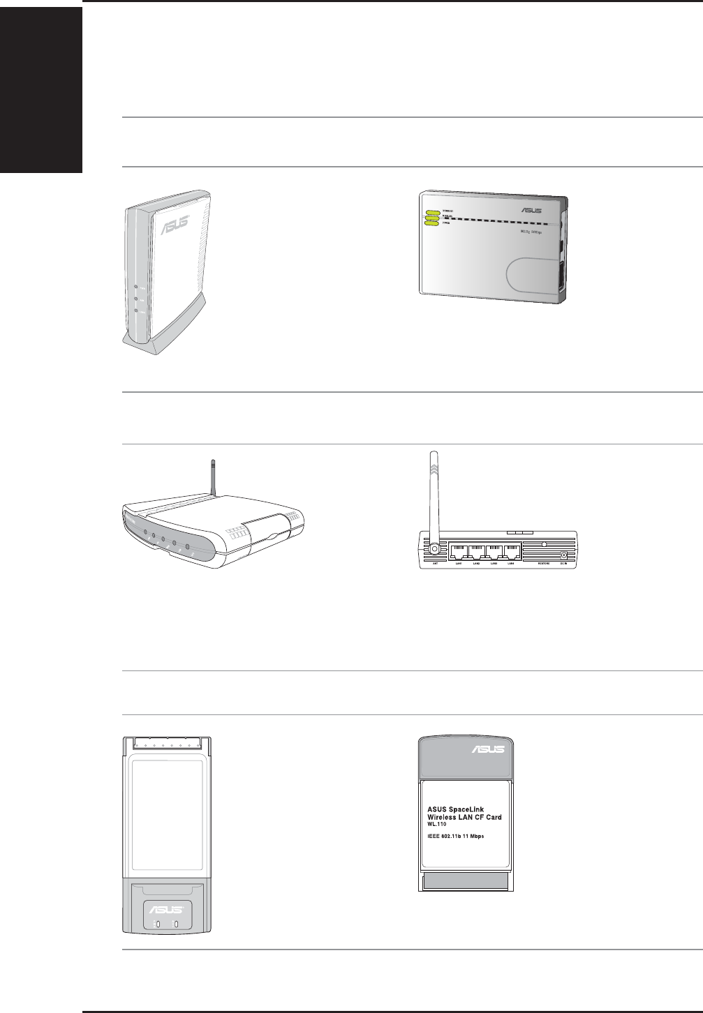
The ASUS WLAN 802.11g
Access Point (WL-300g) creates
a wireless network using the
IEEE 802.11g and 802.11b
wireless standards.
The ASUS Wireless Family
The ASUS Wireless family contains a several wireless network solutions for
802.11g & 802.11b wireless local area networks in the home or office.
The ASUS 802.11b Wireless
CF Card (WL-110) is a IEEE
802.11b wireless LAN adapter
that fits into a Compact Flash
Type II slot in a Portable
Digital Assistant (PDA).
The ASUS WLAN PC Card
(WL-107g) is a wireless LAN
adapter that fits into a PCMCIA
Type II slot in a Notebook PC and
creates a wireless network using
the IEEE 802.11g/b wireless
standards.
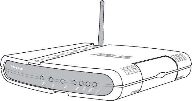
The ASUS WLAN Gateway (WL-500g) creates a
wireless network using the IEEE 802.11g/b wireless
standards and allows sharing a single Internet
connection.
The ASUS 3 in 1
Pocket Access Point
(WL-330g) creates a
wireless network
using the IEEE
802.11g/b wireless
standards.
(The illustrations are not to scale.)
Access Point or Client
Access Point & Router
PCMCIA Client Compact Flash (CF) Client
The ASUS WLAN 802.11g Pocket Router (WL-
530g) creates a wireless network using the IEEE
802.11g and 802.11b wireless standards and allows
sharing a single Internet connection.
1. Introduction
ASUS Wireless Router 13
Chapter 1 - Introduction
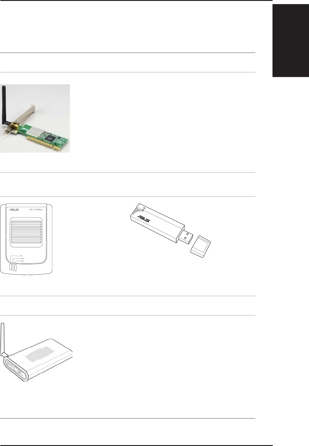
The ASUS USB Wireless LAN Adapter (WL-167g)
is thumb-sized and creates a wireless network using
the IEEE 802.11g/b wireless standards and connects
to any computer using USB2.0 connectivity.
The ASUS USB Wireless
LAN Adapter (WL-160g)
creates a wireless network
using the IEEE 802.11g/b
wireless standards and
connects to any computer
using USB2.0 connectivity.
The ASUS WLAN
PCI Card (WL-
138g) is a wireless
LAN adapter that fits
into a standard PCI
slot in a desktop PC
and creates a wireless
network using the
IEEE 802.11g/b
wireless standards.
(The illustrations are not to scale.)
USB Access Point or Client USB Client
PCI Client
802.11g 54Mbps
Access Point & File Server
The ASUS WLAN 802.11g Access Point (WL-
HDD) creates a wireless network using the IEEE
802.11g and 802.11b wireless standards. Also serves
as a file server (wireless network attached storage).
1. Introduction
Chapter 1 - Introduction
14 ASUS Wireless Router
Wireless Client
Wireless Client
ASUS Wireless Router
LAN
Wireless
Wired Client
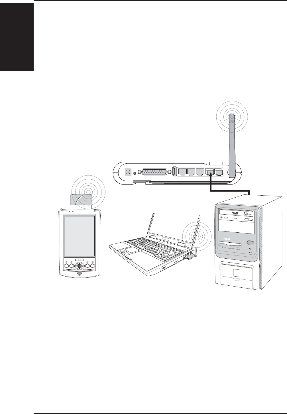
Network Topology
The settings that you need to perform will vary depending on the role that
your ASUS Wireless Router will play.
Network Backbone
No software setting is necessary in the ASUS Wireless Router.
In this topology, the wireless router connects your wired and wireless devices
together to form a local area network (LAN), as shown. To connect a
computer (or other device) to the ASUS Wireless Router, you need a network
cable (UTP-Cat5) with one end connected to one of the LAN ports on the
back of the ASUS Wireless Router and the other in the 10/100 LAN port on
that device. For wireless connections, wireless mobile clients must comply
with the IEEE 802.11b standard.
1. Introduction
ASUS Wireless Router 15
Chapter 1 - Introduction
ASUS Wireless Router
Wireles
s
I
nternet Service Provider
Wired Client
Wireless Client
Wireless Client
WAN
LAN
ADSL or Cable Modem
Internet
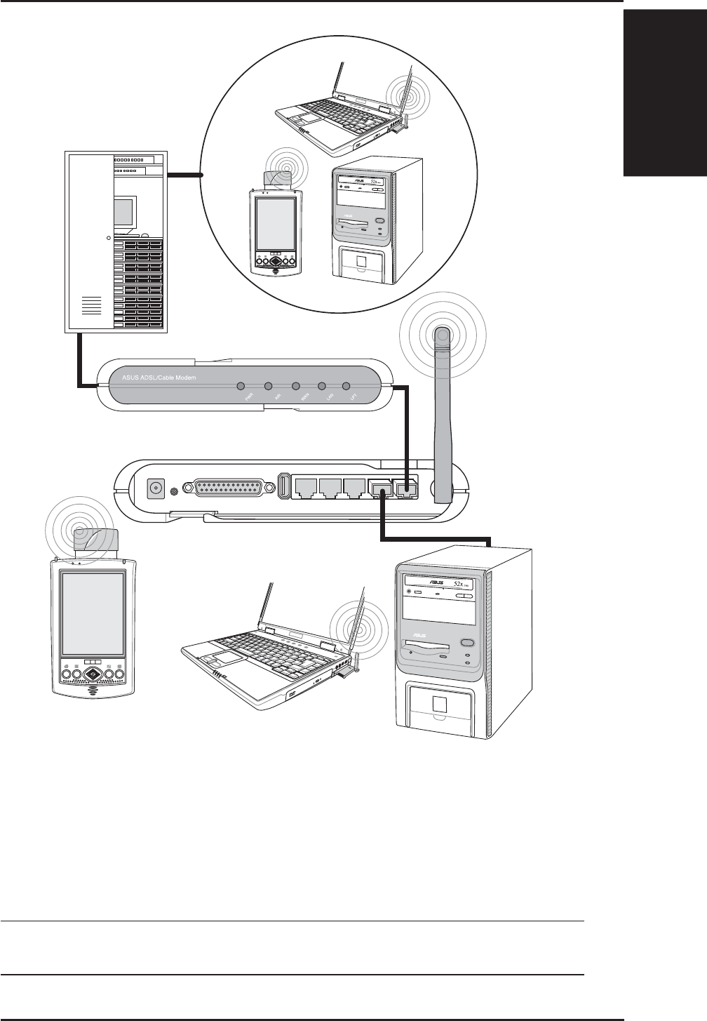
Agent to an ISP
In this topology, the wireless router is not only a backbone of your LAN
but also an agent to your Internet Service Provider (ISP). You may use an
ADSL or Cable modem to communicate with your ISP. Connect the LAN
port on the modem with the WAN port at the back of the ASUS Wireless
Router using a network cable as shown above.
Note: You also need to make sure that other connections on the
ADSL or Cable modem are correct.
1. Introduction
Chapter 1 - Introduction
16 ASUS Wireless Router
Wired Client
Wireless Client
Wireless Client
ASUS Wireless Router
WAN
LAN
Wireless
Network Backbone
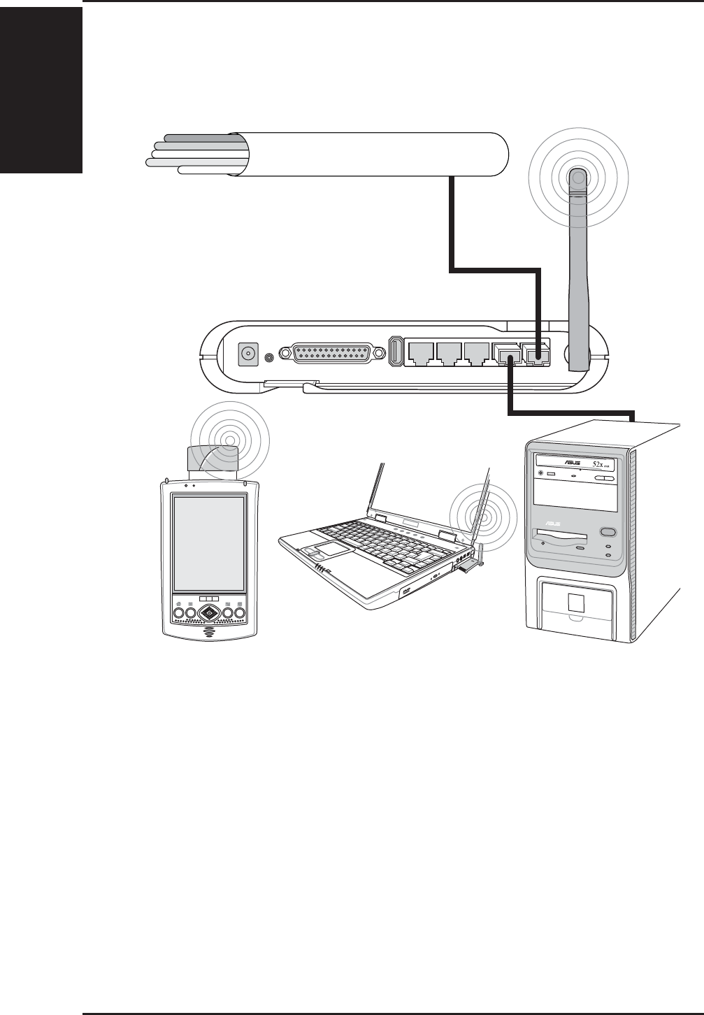
Agent to Another Network
In this topology, the wireless router is an agent between your LAN and
another network. Use a network cable with one end connected to the WAN
port on the wireless router and the other to the other network as shown
above.
1. Introduction
ASUS Wireless Router 17
Chapter 1 - Introduction
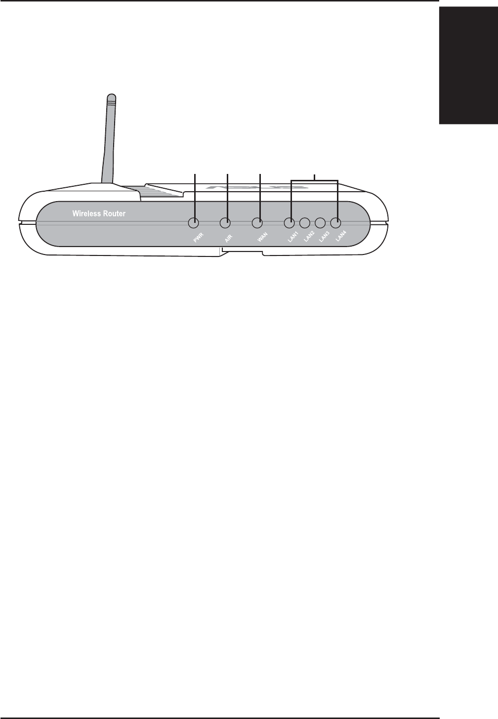
LED Indicators
The LEDs on the front of the ASUS Wireless Router display the status of
the ASUS Wireless Router.
PWR (Power)
Off No power
On System ready
Flashing Firmware upgrade failed
AIR (Wireless Network)
Off No power
On Wireless system ready
Flashing Transmitting or receiving data (wireless)
WAN (Wide Area Network)
Off No power
On Has physical connection to an Ethernet network
Flashing Transmitting or receiving data (through Ethernet wire)
LAN 1-4 (Local Area Network)
Off No power
On Has physical connection to an Ethernet network
Flashing Transmitting or receiving data (through Ethernet wire)
PWR AIR WAN LAN

Chapter 2 - Installation
2. Installation
18 ASUS Wireless Router
2. Installation Procedure
Follow these steps to install the ASUS Wireless Router.
1. Determine the best location for the ASUS Wireless Router. Keep in mind
the following considerations:
• The length of the Ethernet cable that connects the ASUS Wireless
Router to the network must not exceed 100 meters.
• Try to place the ASUS Wireless Router on a flat, sturdy surface as
far from the ground as possible, such as on top of a desk or book-
case, keeping clear of obstructions and away from direct sunlight.
• Try to centrally locate the ASUS Wireless Router so that it will pro-
vide coverage to all of the wireless mobile devices in the area. Orien-
tating the antenna vertically should provide the best reception.
• Use only the power supply that came with this unit. Other power
supplies may fit but the voltage and power may not be compatible.
2. Wall mounting or vertical standing is also possible.
It is the responsibility of the installer and users of the ASUS Wire-
less Router to guarantee that the antenna is operated at least 20
centimeters from any person. This is necessary to insure that the
product is operated in accordance with the RF Guidelines for Hu-
man Exposure which have been adopted by the Federal Communi-
cations Commission.
4. LAN Connection: Attach one end of an RJ-45 Ethernet cable to the ASUS
Wireless Router’s LAN port (any one of the four) and attach the other end
to the RJ-45 Ethernet cable to your desktop computer.
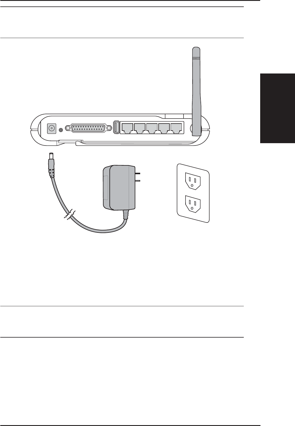
5. Power Connection: The ASUS Wireless Router requires power from an
external power supply. The ASUS Wireless Router ships with a UL listed,
Class 2 power supply (5V). Attach one end of the DC power adapter to the
back of the ASUS Wireless Router and the other end to a power outlet.
The Power LED on the front of the ASUS Wireless Router will light up
when the unit is powered ON. In addition, the green LAN or WAN LEDs
will turn ON to indicate that the ASUS Wireless Router has a physical
Ethernet network connection.
2. Installation
Chapter 2 - Installation
ASUS Wireless Router 19
Warning: Use the ASUS Wireless Router only with the power adapter
supplied in the product package. Using another power supply may
damage the ASUS Wireless Router.
6. Printer Connection: Connect a printer to the Wireless Router printer
port (WL500g/WL500b only) or USB port to use the router as a printing
server for your local network.
7. USB Connection: Connect a supported USB web camera or USB
storage device to the Wireless Router USB port.
Note: Before using an embedded USB application or device, refer
to the USB storage and USB camera support list on the ASUSTeK
Web site at the following Internet address: http://www.asus.com.
Chapter 2 - Installation
2. Installation
20 ASUS Wireless Router
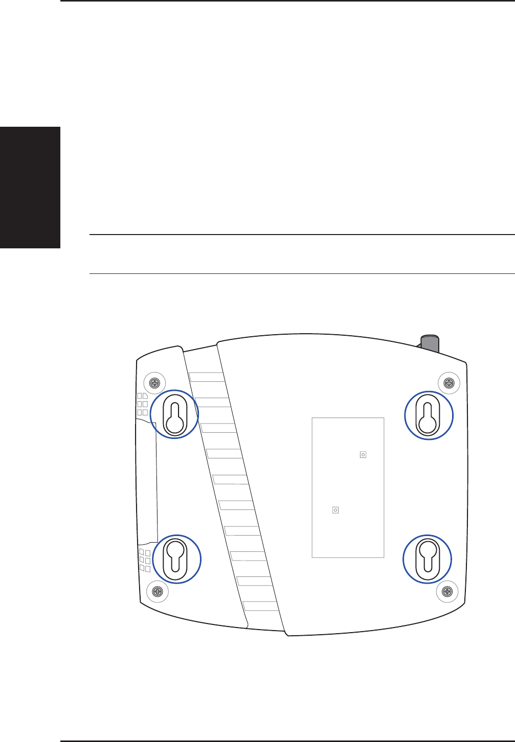
Wall Mounting Option
Out of the box, the ASUS Wireless Router is designed to sit on a raised flat
surface like a file cabinet or book shelf. The unit may also be converted for
mounting to a wall or ceiling.
Follow these steps to mount the ASUS Wireless Router to a wall:
1. Look on the underside for the four mounting hooks.
2. Mark two upper holes in a flat surface using the provided hole template.
3. Tighten two screws until only 1/4” is showing.
4. Latch the upper two hooks of the ASUS Wireless Router onto the screws.
Note: Readjust the screws if you cannot latch the ASUS Wireless
Router onto the screws or if it is too loose.
2. Installation
Chapter 2 - Installation
ASUS Wireless Router 21
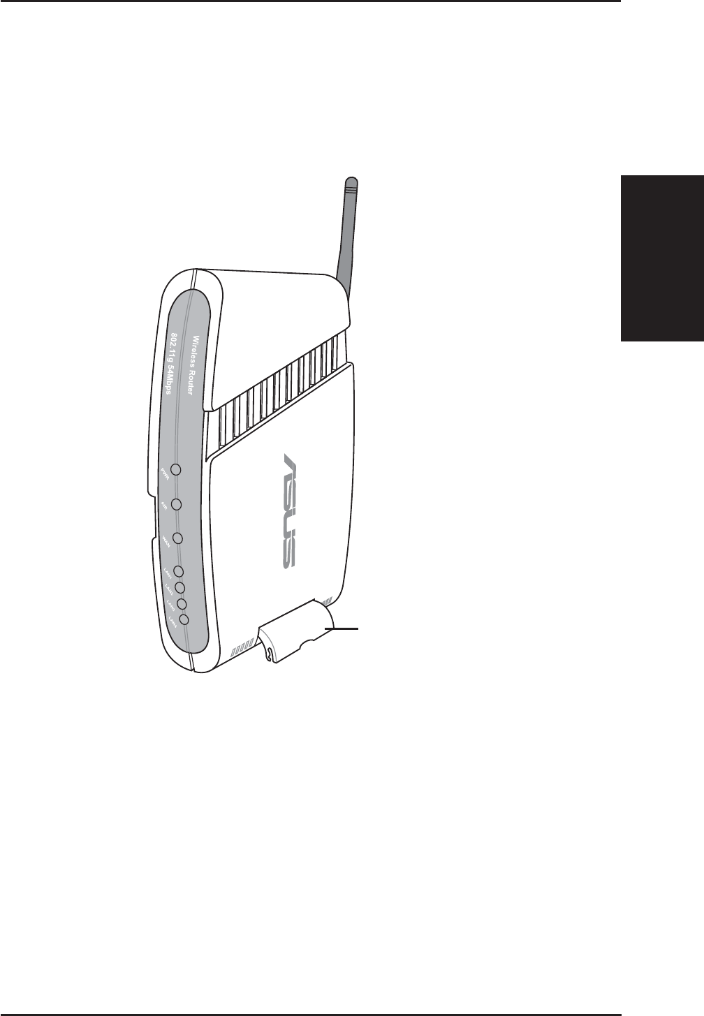
Vertical Standing Option
The ASUS Wireless Router can also stand on its side to save space. Two
hinges can be opened on the right side to support vertical standing. Orientate
the antenna so that it points upwards.
Support Hinge
Chapter 2 - Installation
2. Installation
22 ASUS Wireless Router
Connecting to the ASUS Wireless Router
Wired Connection
One RJ-45 cable is supplied with the ASUS Wireless Router. Auto crossover
function is designed into the ASUS Wireless Router so you can use either a
straight-through or a crossover Ethernet cable. Plug one end of the cable
into the WAN port on the rear of the ASUS Wireless Router and the other
end into the Ethernet port of your ADSL or Cable modem.
Wireless-Connection
Refer to your wireless adapter user’s manual on associating with the ASUS
Wireless Router. The default SSID of the ASUS Wireless Router is “default”
(lower case), encryption is disabled and open system authentication is used.
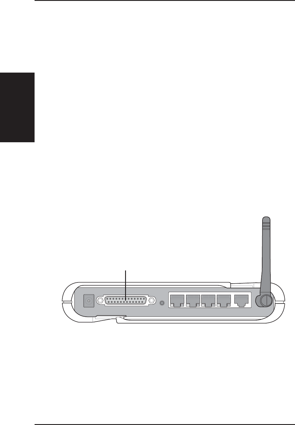
Printer Connection (WL500g/WL500b only)
A DB25 parallel cable should be supplied with your printer. Plug the male
connector of this parallel cable into the printer port on the rear of the ASUS
Wireless Router and the centronics end into your printer.
Printer Port
3. Utilities
ASUS Wireless Router 23
Chapter 3 - Software Configuration
3. Software Configuration
Configuring the ASUS Wireless Router
The ASUS Wireless Router can be configured to meet various usage
scenarios. Some of the factory default settings may suit your usage; however,
others may need changing. Prior to using the ASUS Wireless Router, you
must check the basic settings to guarantee it will work in your environment.
Configuring the ASUS Wireless Router is done through a web browser.
You need a Notebook PC or desktop PC connected to the ASUS Wireless
Router (either directly or through a hub) and running a web browser as a
configuration terminal. The connection can be wired or wireless. For the
wireless connection, you need an IEEE 802.11g/b compatible device, e.g.
ASUS WLAN Card, installed in your Notebook PC. You should also disable
WEP and set the SSID to “default” for your wireless LAN device. If you
want to configure the ASUS Wireless Router or want to access the Internet
through the ASUS Wireless Router, TCP/IP settings must be correct.
Normally, the TCP/IP setting should be on the IP subnet of the ASUS
Wireless Router.
Note: Before rebooting your computer, the ASUS Wireless Router
should be switched ON and in ready state.
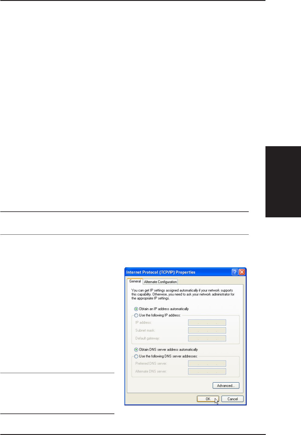
Setting IP address for Wired or Wireless Connection
Get IP Automatically
The ASUS Wireless Router
incorporates a DHCP server so the
easiest method is to set your PC to
get its IP address automatically and
reboot your computer. So the
correct IP address, gateway, DNS
(Domain Name System Server)
can be obtained from the ASUS
Wireless Router.
Note: Before rebooting your
PC, the ASUS Wireless Router
should be switched ON and in
ready state.
3. Utilities
24 ASUS Wireless Router
Chapter 3 - Software Configuration
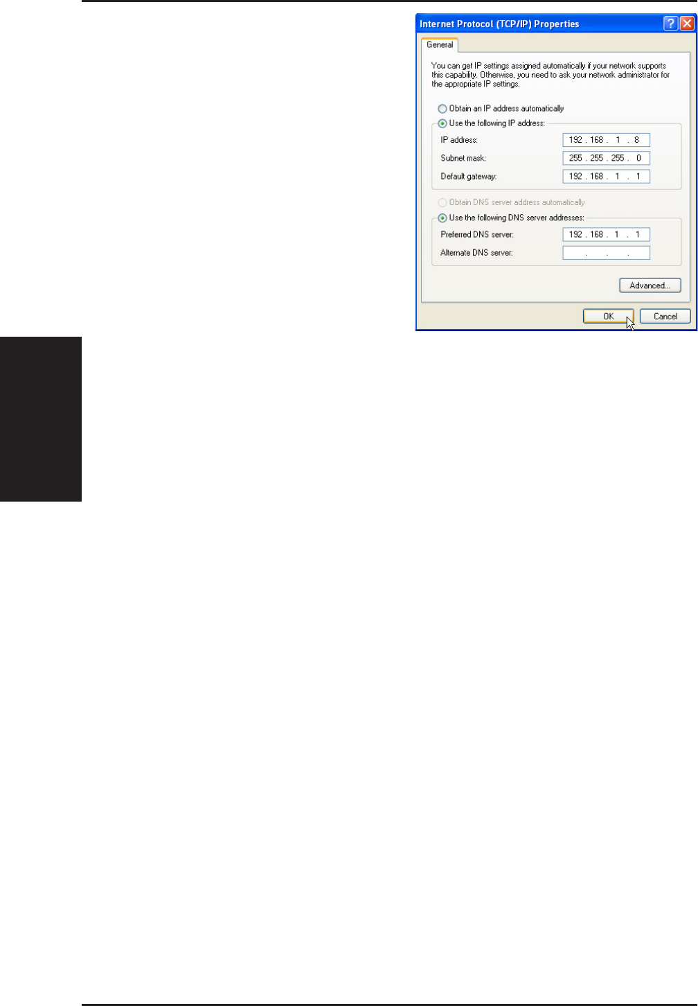
Setting IP Manually
If you want to set your IP address
manually, the following default
settings of the ASUS Wireless
Router should be known:
• IP address 192.168.1.1
• Subnet Mask 255.255.255.0.
If you set your computer’s IP
manually, it needs to be on the same
segment. For example:
• IP address 192.168.1.xxx (xxx
can be any number between 2
and 254 that is not used by
another device)
• Subnet Mask 255.255.255.0 (same as the ASUS Wireless Router)
• Gateway 192.168.1.1 (this is the ASUS Wireless Router)
• DNS 192.168.1.1 (ASUS Wireless Router IP address or your own).
3. Utilities
ASUS Wireless Router 25
Chapter 3 - Software Configuration
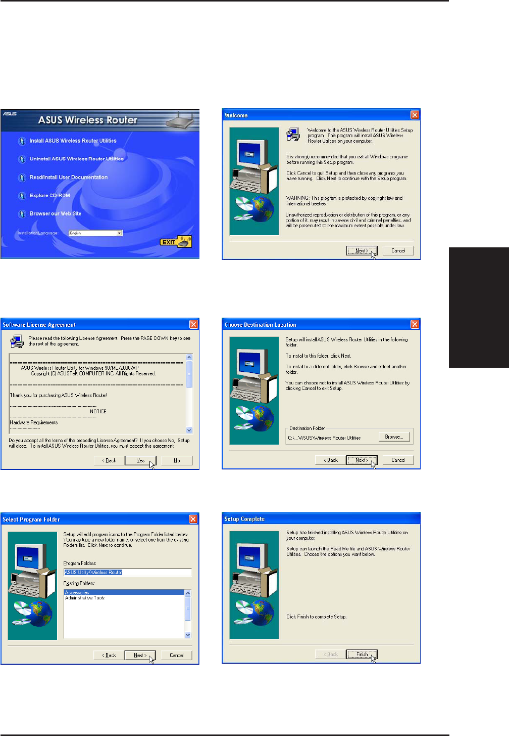
Installing the ASUS Wireless Router Utilities
Follow these steps to install the ASUS Wireless Router Utilities in Microsoft
Windows. Insert the support CD provided with the ASUS Wireless Router and
the menu will appear. (Double-click setup.exe if your autorun has been disabled.)
(1) Select a language and click Install
ASUS Wireless Router Utilities.(2) Click Next after reading the welcome
screen.
(3) Click Yes after reading the license
agreement.
(5) Click Next to accept the default
program folder or enter another.
(4) Click Next to accept the default
destination folder or enter another.
(6) Click Finish when setup is complete.
3. Utilities
26 ASUS Wireless Router
Chapter 3 - Software Configuration
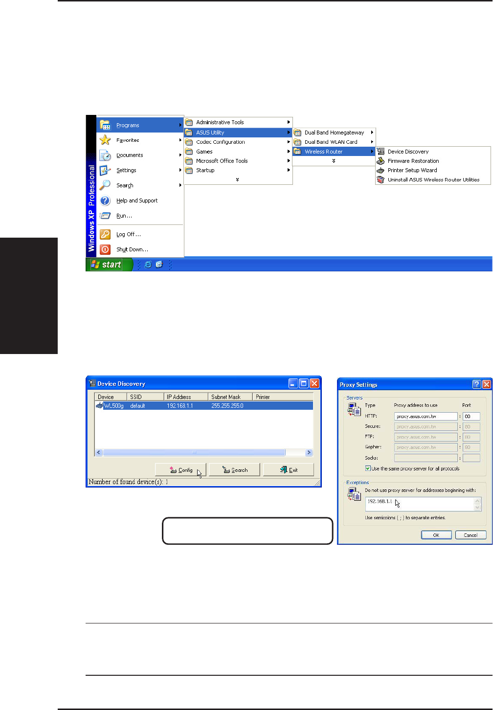
Using the Wireless Router for the First Time
1. ASUS Wireless Router Utilities
Run Device Discovery from “ASUS Utility” in Windows Start Programs.
2. Connect to the ASUS WLAN Web Manager
Run the ASUS WLAN Device Discovery from the Start menu and click
Config when the device is found.
If your computer’s IP is not on the same subnet as the ASUS Wireless Router
(192.168.1.X), you will be asked to change it. The IP address can be any number
from 2 to 254 that is not used by another device. Gateway is not required.
Note: Using a proxy server (Microsoft® Internet Explorer) for your
LAN requires that you set an exception for the ASUS Wireless Router
or else connection will fail.
Add 192.168.1.1 in the Exceptions box if you are
using a proxy server (Microsoft® Internet Explorer).
Microsoft® Internet Explorer
3. Utilities
ASUS Wireless Router 27
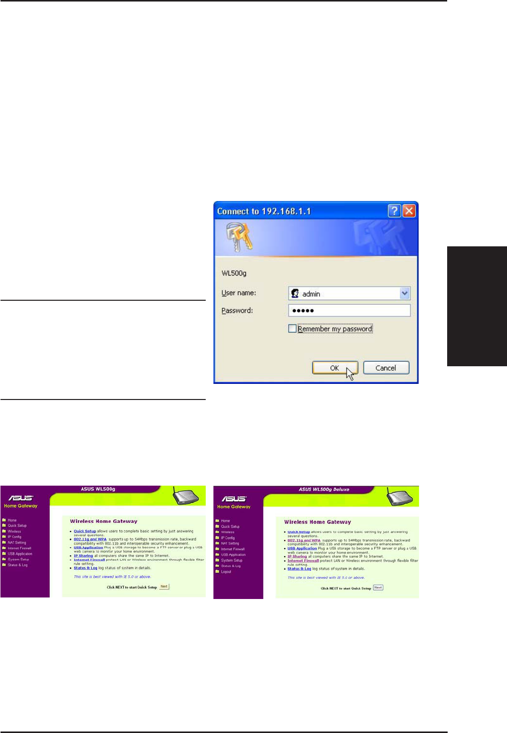
Chapter 3 - Software Configuration
User Name & Password
Once connected, a window will ask
for the User name and Password in
order to log in. The factory default
values are “admin” and “admin”.
Note: If you cannot find any the
ASUS Wireless Routers due to
a problem in the IP settings,
push and hold the “Restore”
button over five seconds to re-
store factory default settings.
Enter Address or Name Manually
You can also open your PC’s web browser and enter the name or the default
IP address of the ASUS Wireless Router:
WL500g
http://my.router or http://my.WL500g or http://192.168.1.1
WL500g Deluxe
http://my.router or http://my.WL500gx or http://192.168.1.1
Home Page
After logging in, you will see the ASUS Wireless Router home page.
WL500g WL500g Deluxe
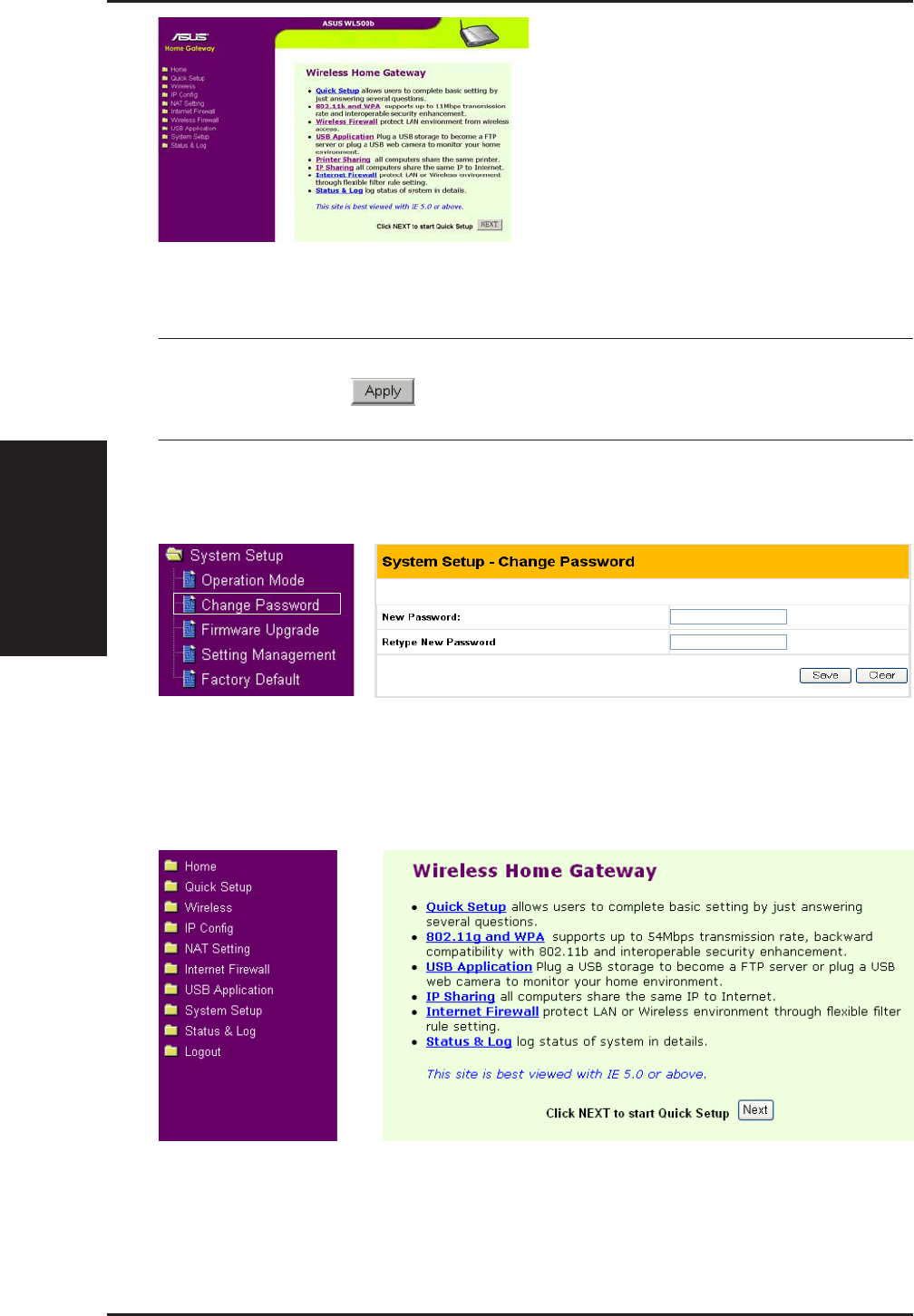
3. Utilities
28 ASUS Wireless Router
Chapter 3 - Software Configuration
3. Set your own password
4. Use Quick Setup
IMPORTANT: After entering information on any page, click the
“Apply” button . If you click any other link, you will be di-
rected to another page and lose your new settings.
WL500b
3. Utilities
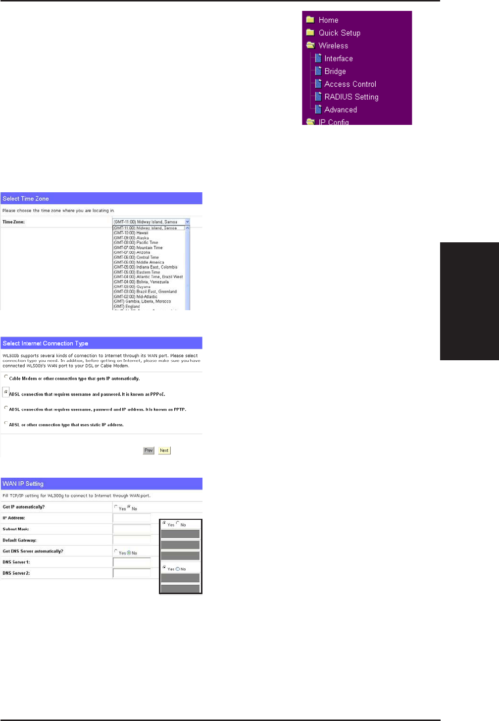
ASUS Wireless Router 29
Chapter 3 - Software Configuration
Select your time zone or the closest
region. Click Next to continue.
Home Gateway Mode
There are three operation modes in the ASUS
Wireless Router. The default operation mode of the
ASUS Wireless Router is Home Gateway Mode.
Please refer to “System Setup” – “Operation Mode”
in detail. To start quick setup, click Next to enter
the “Quick Setup” page. Follow the instructions to
setup the ASUS Wireless Router.
Quick Setup in Home Gateway Mode
Select the connection type. Click
Next to continue.
Select “No” to enter the information
manually. “Yes” will disable the field.
Click Next to continue.
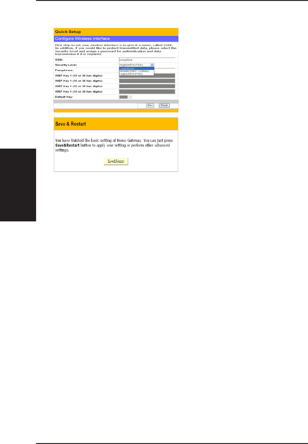
3. Utilities
30 ASUS Wireless Router
Chapter 3 - Software Configuration
To set up your wireless interface,
you must first give it an SSID
(Service Set Identifier). The SSID
is a unique identifier attached to
packets sent over WLANs. This
identifier emulates a password
when a wireless device attempts
communication on the WLAN.
Because an SSID distinguishes
WLANs from each other, access
points and wireless devices trying
to connect to a WLAN must use the
same SSID.
Also, if you want to protect
transmitted data, select a middle or high Security Level.
Middle: allows only those users with the same WEP key to connect to this
access point and to transmit data using 128-bit WEP encryption.
High: allows only those users with the same WPA pre-shared key to connect
to this access point and to transmit data using TKIP encryption.
Click Finish to continue. You are prompted to save the settings. Click
Save&Restart to save the settings to the ASUS Wireless Router and enable
the new settings.
Home Gateway Mode (Cont.)
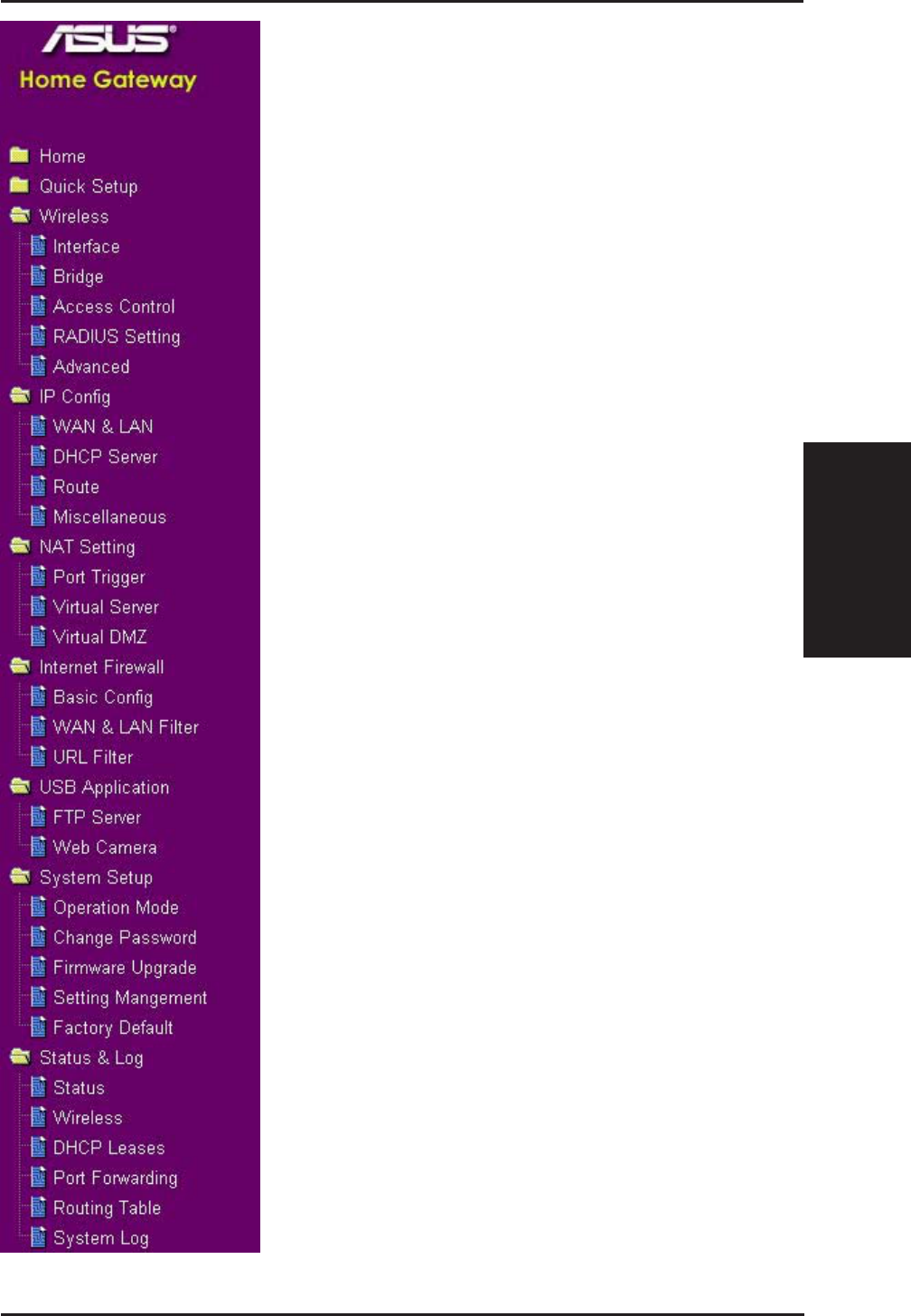
3. Utilities
ASUS Wireless Router 31
Chapter 3 - Software Configuration
To adjust other settings, click an item
on the menu to reveal a submenu and
follow the instructions to setup the
ASUS Wireless Router. Tips are
given when you move your cursor
over each item. The following have
submenu items:
• Wireless
• IP Config
• NAT Setting
• Internet Firewall
• USB Application
• System Setup
• Status & Log
3. Utilities
32 ASUS Wireless Router
Chapter 3 - Software Configuration
Wireless
Click an item on the menu to reveal a submenu.
Follow the instructions to set up the ASUS Wireless
Router. Tips are displayed when you move your
cursor over an item.
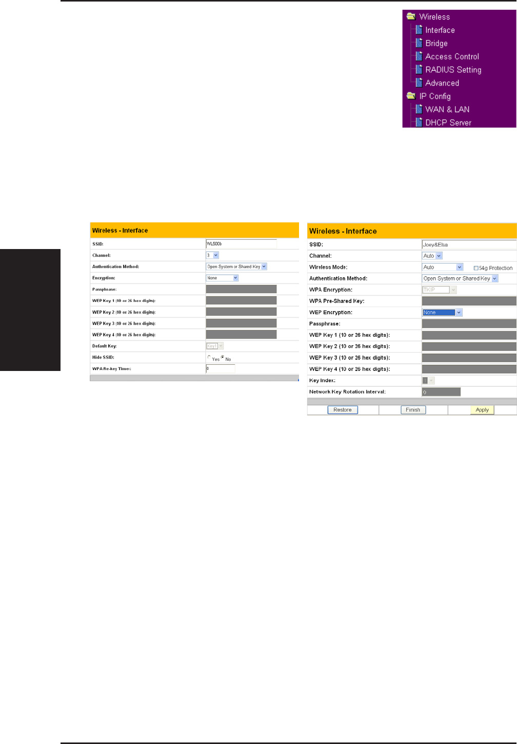
Interface
WL500b WL500g/WL500g Deluxe
SSID
The SSID is an identification string of up to 32 ASCII characters that
differentiate one ASUS Wireless Router AP or Access Point from other
manufacturers. The SSID is also referred to as the “ESSID” or “Extended
Service Set ID.” You can use the default SSID and radio channel unless
more than one ASUS Wireless Router or Access Point is deployed in the
same area. In that case, you should use a different SSID and radio channel
for each ASUS Wireless Router or Access Point. All ASUS Wireless Routers
and ASUS 802.11g/802.11b WLAN client adapters must have the same
SSID to allow a wireless mobile client to roam between the ASUS Wireless
Routers . By default, the SSID is set to “default”.

3. Utilities
ASUS Wireless Router 33
Chapter 3 - Software Configuration
Wireless (Cont.)
Channel
The 802.11g and 802.11b specifications supports up to 14 overlapping
channels for radio communication. To minimize interference, configure
each ASUS 802.11g AP to be non-overlapping; select Auto from the Channel
drop-down list to enable the system to select a clear channel during boot up
as your operating channel.
Ensure that ASUS Wireless Routers sharing the same channel (or channels
which are close in number) are as far away from each other as possible,
based on the results of your site survey of the facility. There is a site survey
utility on the ASUS Wireless Router setup CD.
Wireless Mode (WL500g/WL500g Deluxe Only)
This field indicates the 802.11g interface mode. Selecting “Auto” allows
802.11g and 802.11b clients to connect to the ASUS Wireless Router.
Selecting “54g Only” maximizes performance, but prevents 802.11b clients
from connecting to the ASUS Wireless Router. If “54g Protection” is
checked, G-Mode protection of 11g traffic is enabled automatically in the
presence of 11b traffic.

3. Utilities
34 ASUS Wireless Router
Chapter 3 - Software Configuration
Authentication
Method Encryption Passphrase WEP Key 1~4
Open or shared key None Not required Not required
WEP-64 bits 1~64 characters 10 hex
WEP-128 bits 1~64 characters 26 hex
Shared key WEP-64 bits 1~64 characters 10 hex
WEP-128 bits 1~64 characters 26 hex
WPA-PSK
^
TKIP only * 8~63 characters Not required
AES only * 8~63 characters Not required
WPA
^
TKIP only * Not required Not required
AES only * Not required Not required
Radius with 802.1x
^
Auto Not required Not required
WEP-64 bits 1~64 characters 10 hex
WEP-128 bits 1~64 characters 26 hex
* WL500g/WL500g Deluxe supports AES and TKIP encryption for WPA.
^ WL500b does not support WPA and Radius with 802.1x and WL500b only supports TKIP encryption for WPA-PSK.
WEP Encryption
Traditional WEP encryption is applied when “Open or Shared Key”, “Shared
Key” or “Radius with 802.1x” authentication methods are selected.
WL500g/WL500g Deluxe: When “WPA” or “WPA-PSK” authentica-
tion methods are selected, you still can set WEP encryption for
those clients that do not support WPA/WPA-PSK. Please note that
Key Index for WEP key is limited to 2 or 3 when both WPA and WEP
encryption are supported at the same time.
64/128-bit versus 40/104-bit
The following section explains low-level (64-bit) and high-level (128-bit)
WEP Encryption schemes:
Wireless (Cont.)

3. Utilities
ASUS Wireless Router 35
Chapter 3 - Software Configuration
Wireless (Cont.)
64-bit WEP Encryption
64-bit WEP and 40-bit WEP are the same encryption method and can
interoperate in a wireless network. This level of WEP encryption uses a
40-bit (10 Hex character) encryption scheme as a secret key, which is set
by the user, and a 24-bit “Initialization Vector” scheme, which is not under
user control.
Together these two schemes make a 64-bit (40 + 24) encryption scheme.
Some vendors refer to this level of WEP as 40-bit and others refer to this as
64-bit. ASUS WLAN products use the term 64-bit when referring to this
lower level of encryption.
128-bit WEP Encryption
104-bit WEP and 128-bit WEP are the same encryption method and can
interoperate on a wireless network. This level of WEP encryption uses a
104-bit (26 Hex character) encryption scheme as a secret key which is set
by the user, and a 24-bit “Initialization Vector”, which is not under user
control.
Together these two schemes make a 128-bit (104 + 24) encryption scheme.
Some vendors refer to this level of WEP as 104-bit and others refer to this
as 128-bit. ASUS WLAN products use the term 128-bit when referring to
this higher level of encryption.
Passphrase
Selecting “WEP-64bits” or “WEP-128bits” in the Encryption field generates
four WEP keys automatically. A combination of up to 64 letters, numbers,
or symbols is required. Alternatively, leave this field blank and type in four
WEP keys manually.
¥WEP-64bit key: 10 hexadecimal digits (0~9, a~f, and A~F)
¥WEP-128bit key: 26 hexadecimal digits (0~9, a~f, and A~F)
Note: The ASUS WLAN family of products uses the same algorithm
to generate WEP keys, eliminating the need for users to remember
passwords and to maintain compatibility between products. How-
ever, using this method to generate WEP keys is not as secure as
manual assignment.

3. Utilities
36 ASUS Wireless Router
Chapter 3 - Software Configuration
Wireless (Cont.)
WEP Key
You can set a maximum of four WEP keys. A WEP key is either 10 or 26
hexadecimal digits (0~9, a~f, and A~F) based on whether you select 64bits
or 128bits in the WEP pull-down menu. The ASUS Wireless Router and
ALL of its wireless clients MUST have at least the same default key.
Key Index
The Default Key field lets you specify which of the four encryption keys
you use to transmit data on your wireless LAN. As long as the ASUS
Wireless Router or wireless mobile client with which you are communicating
has the same key in the same position, you can use any of the keys as the
default key. If the ASUS Wireless Router and ALL of its wireless clients
use the same four WEP keys, select “key rotation” to maximize security.
Otherwise, choose one key in common as the default key.
Network Rotation Key Interval
This field specifies the time interval (in seconds) after which a WPA group
key is changed. Enter ‘0’ (zero) to indicate that a periodic key-change is
not required.
3. Utilities
ASUS Wireless Router 37
Chapter 3 - Software Configuration
Wireless
Click an item on the menu to reveal a submenu.
Follow the instructions to set up the ASUS Wireless
Router. Tips are displayed when you move your
cursor over an item.
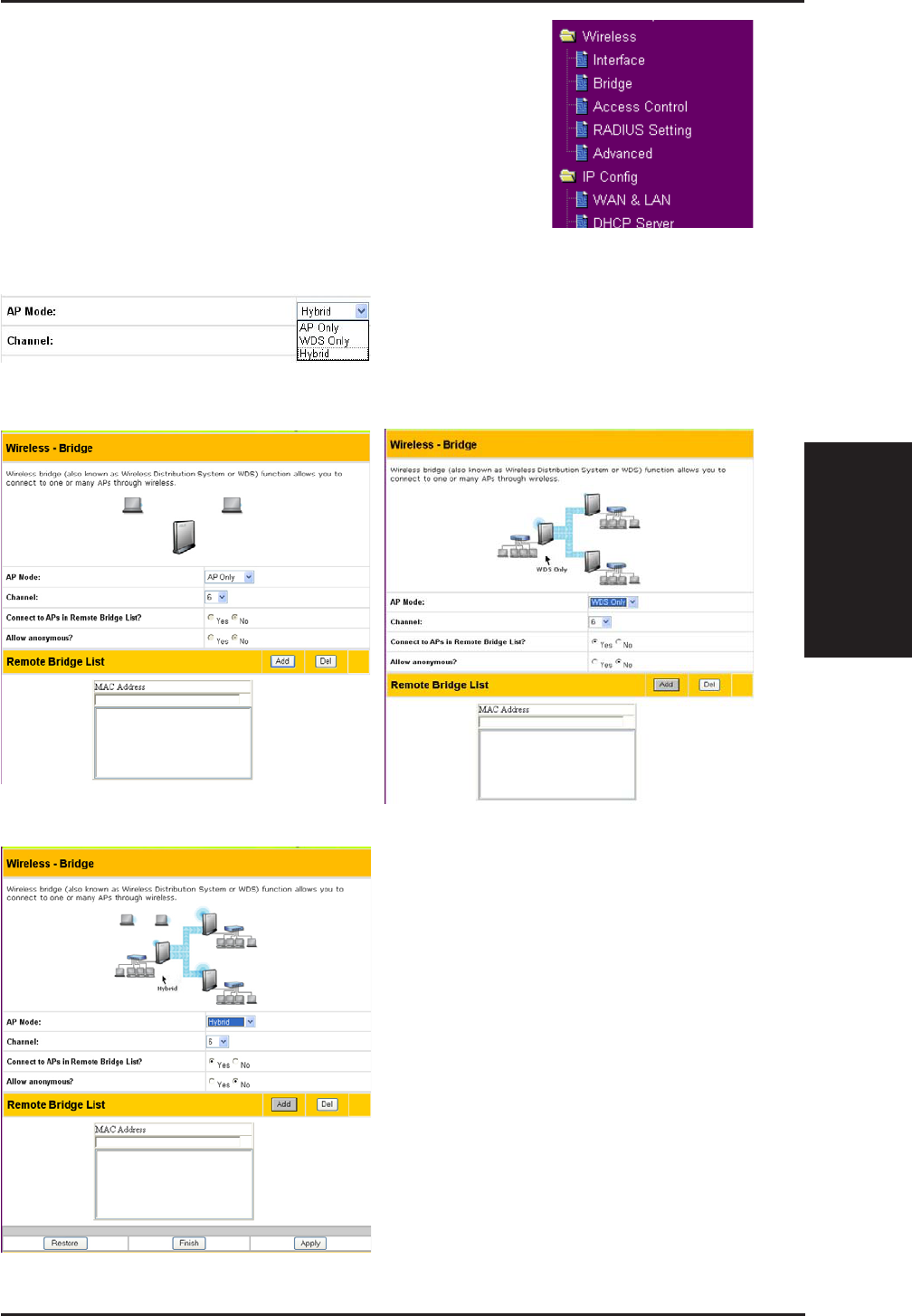
Bridge/Access Control List
AP Only WDS Only (WL500g/WL500g Deluxe)
Hybrid
Wireless bridge (also known as
Wireless Distribution System or
WDS) allows you to connect to one
or many Access Points.

3. Utilities
38 ASUS Wireless Router
Chapter 3 - Software Configuration
Wireless (Cont.)
AP Mode
AP (Access Point) Mode configures the ASUS Wireless Router for a specific
application. By default, the ASUS Wireless Router is configured as an
Access Point which enables wireless mobile clients to connect wirelessly
to a wired Ethernet network. The following options are available from the
drop-down list:
AP Only: the ASUS Wireless Router acts only as an Access Point.
WDS Only (WL500g/WL500g Deluxe): the ASUS Wireless Router
can only communicate with other Access Points.
Hybrid: Hybrid allows you to use the ASUS Wireless Router both as
an access point and as a wireless bridge.
Channel
Both Access Points in Wireless Bridge mode must be set to the same channel.
Connect to APs in Remote Bridge List (Yes/No)
Select Yes to connect to access points in the remote bridge list.
Allow anonymous? (Yes/No) (WL500g/WL500g Deluxe)
Select Yes to allow users without accounts to connect.
Note: If “Connect to APs in Remote Bridge List” and “Allow Anony-
mous” are both set to “No”, it means that this AP will not connect with
other APs and therefore the AP mode setting will return to “AP Only”.
3. Utilities
ASUS Wireless Router 39
Chapter 3 - Software Configuration
Wireless (Cont.)
MAC Address
Enter the MAC address of the target ASUS Wireless Router in order to
designate which ASUS Wireless Router will be the partner for this ASUS
Wireless Router.
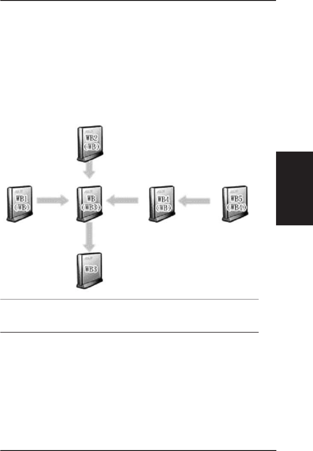
You can setup your wireless environment as shown in this figure:
Note: The content in braces “( )” is the MAC address in the Remote
Bridge List of the AP. For example, WB1 have the MAC address of
WB in its Remote Bridge List.
In this case, there are six ASUS Wireless Routers and they are linked as
wireless bridges. Take one of them, named WB, as an example. WB is not
in “AP Only” mode and “Connect to APs in Remote Bridge List” is set as
“Yes”, so it can connect to WB3. Meanwhile, “allow anonymous” is set as
“Yes” or “Allow anonymous” is set as “No” but it has the MAC addresses
of WB1, WB2, and WB4 in the “Remote Bridge List”, so it can be connected
by WB1, WB2, and WB4.
3. Utilities
40 ASUS Wireless Router
Chapter 3 - Software Configuration
Wireless
Click an item on the menu to reveal a submenu.
Follow the instructions to set up the ASUS Wireless
Router. Tips are displayed when you move your
cursor over an item.
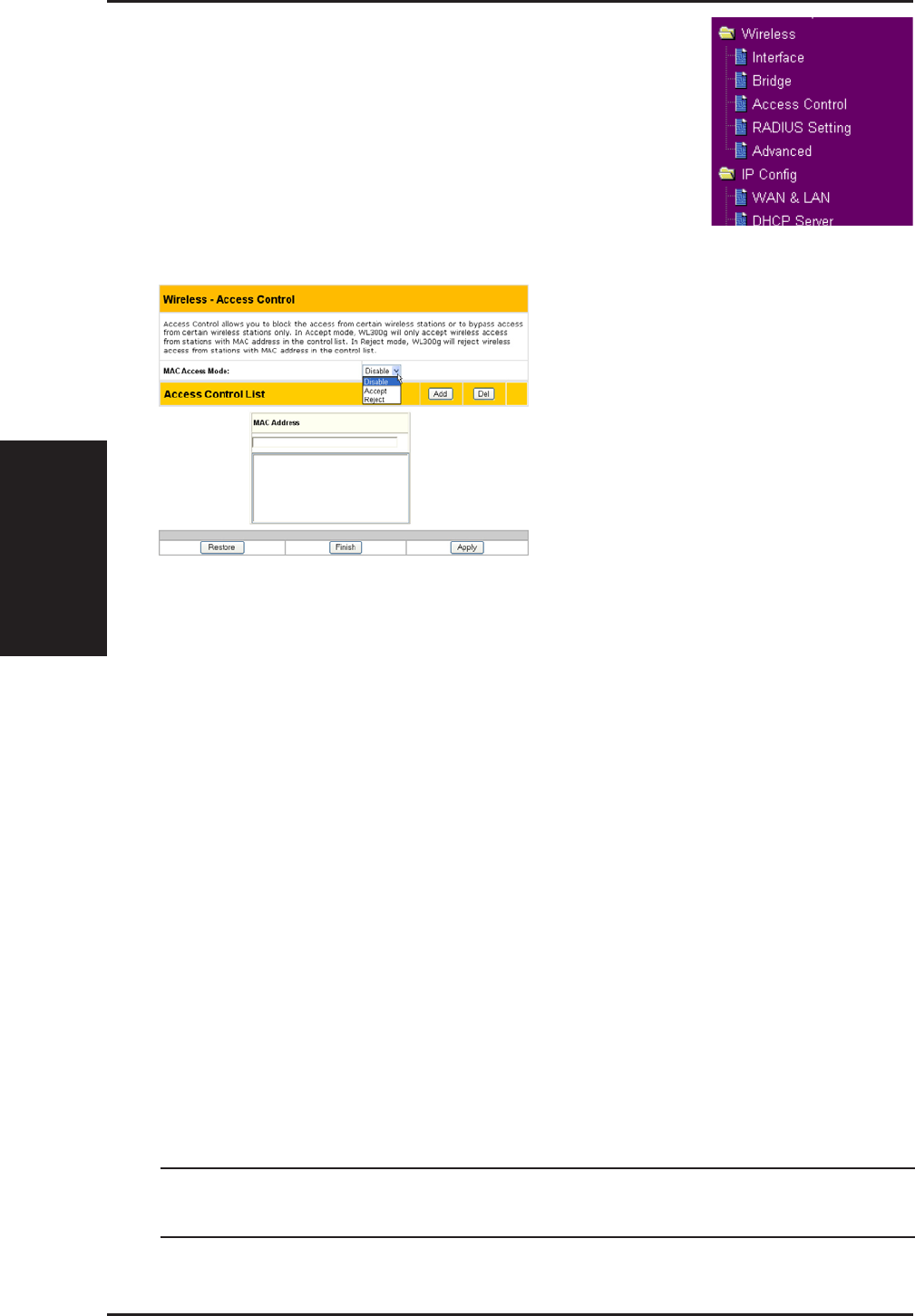
Access Control
Note: Click the “Finish” button to save your new settings and re-
start the ASUS Wireless Router or click “Save” and restart later.
To add security, the ASUS Wireless Router has the ability to only associate
with or not associate with wireless mobile clients that have their MAC
address entered into this page.
The default setting of “Disable” will allow any wireless mobile client to
connect. “Accept” will only allow those entered into this page to connect.
“Reject” will prevent those entered into this page from connecting.
Adding a MAC Address
To add a MAC address, enter the 12 hexadecimal characters into the white box
next to “MAC Address:” and click the Add button. The MAC address will be
placed in the control list below. Only a total of 31 MAC addresses can be entered
into this page so determine which will be the lesser; those you wish to accept or
those you wish to reject and click the appropriate “MAC Access Mode”.
Pull down menu items:
Disable (no info required)
Accept (need to input information)
Reject (need to input information)
3. Utilities
ASUS Wireless Router 41
Chapter 3 - Software Configuration
Wireless
Click an item on the menu to reveal a submenu.
Follow the instructions to set up the ASUS Wireless
Router. Tips are displayed when you move your
cursor over an item.
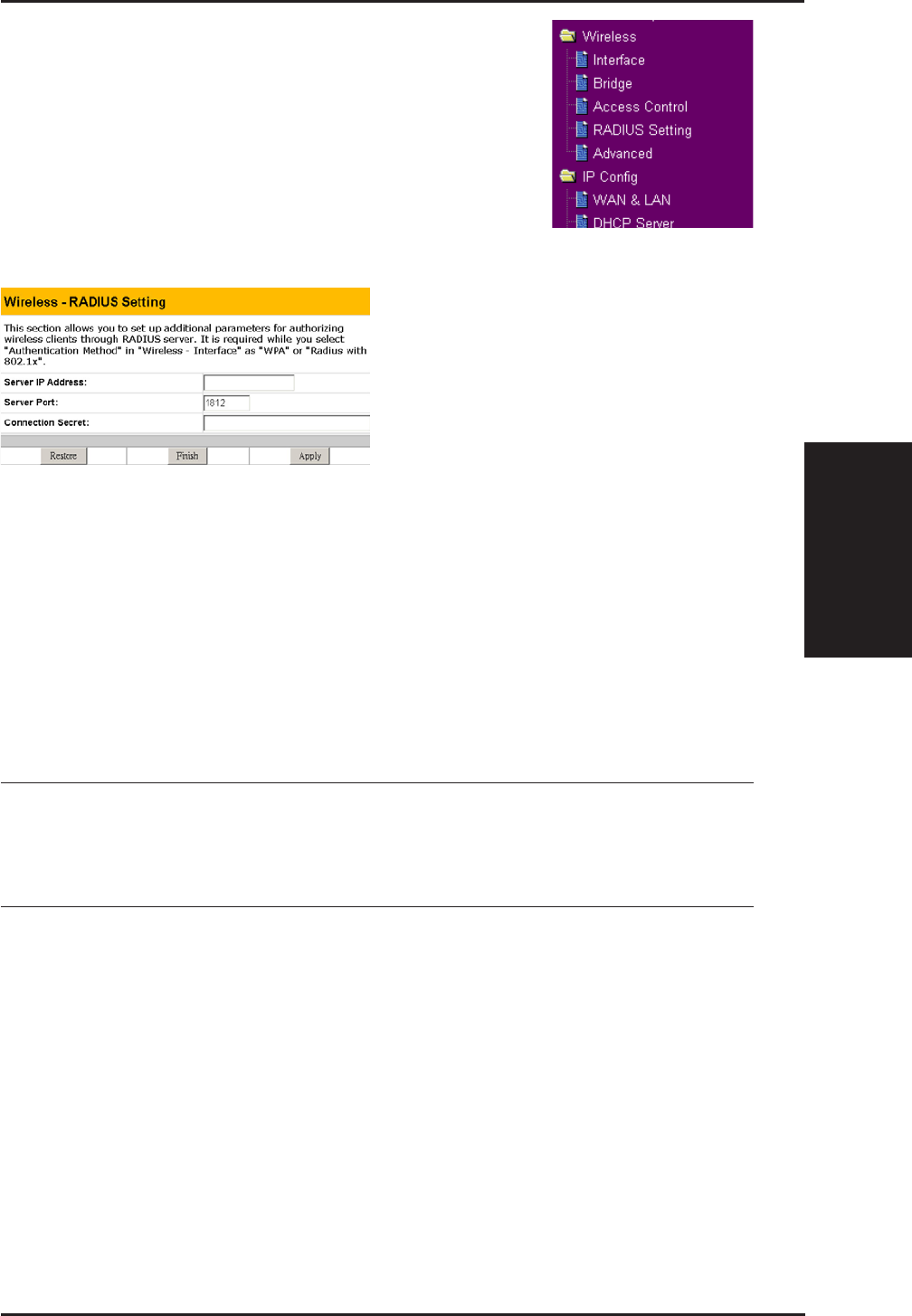
Radius Setting (WL500g/WL500g Deluxe)
This section enables you to set up
additional parameters for connection
with a RADIUS Server. Values are
required for this page when the
Authentication Method field in the
Wireless - Interface screen are set as
“WPA” or “Radius with 802.1x”.
Refer to Authentication Method on
page 32.
Server IP Address – specifies the IP address of the RADIUS server to use
for 802.1X wireless authentication and dynamic WEP key derivation.
Server Port – specifies the UDP port number used by the RADIUS server.
Login Secret – specifies the password used to initialize a RADIUS
connection.
Note: A RADIUS server is used for remote user authentication and
accounting. It is primarily used by Internet Service Providers, but
can also be used on any network that needs a centralized authenti-
cation function for its workstations.
3. Utilities
42 ASUS Wireless Router
Chapter 3 - Software Configuration
Wireless
Click an item on the menu to reveal a submenu.
Follow the instructions to set up the ASUS Wireless
Router. Tips are displayed when you move your
cursor over an item.
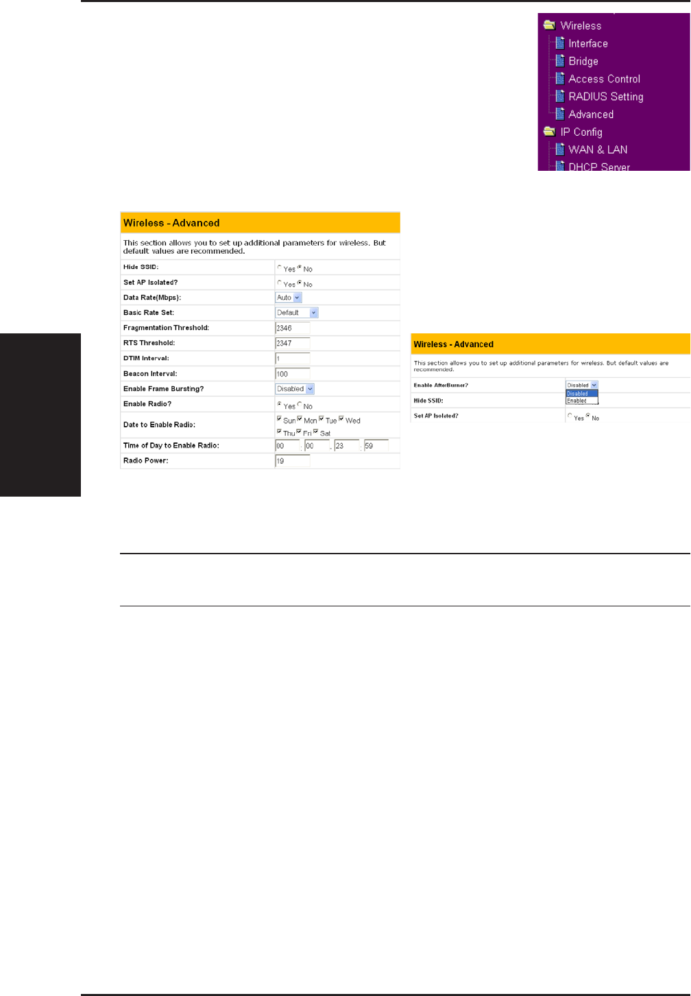
Advanced
This section allows you to set up
additional parameters for the wireless
router function. We recommend that
you use the default values for all
items in this window.
Enable AfterBurner: (WL500g Deluxe) - Set to Enable to increase
performance for clients (such as WL100gx) that support this function.
Note: Your network speed will slow down if you have mixed 802.11g
and Afterburner clients.
Hide SSID - By default, “No” is selected so that wireless mobile users can
see your ASUS Wireless Router’s SSID and join. If “Yes” is selected, your
ASUS Wireless Router will not show in site surveys by wireless mobile
clients and they will have to manually enter your ASUS Wireless Router’s
SSID. If you want to restrict access to “your” ASUS Wireless Router , this
is a simple way to do it but for security reasons, don’t forget to change the
SSID to something other than “default”.
Set AP Isolated (WL500g/WL500g Deluxe) - Selecting Yes to prevent
wireless client from communicating with each other.
Data Rate (Mbps) (WL500g/WL500g Deluxe) - This field allows you to
specify the transmission rate. Leave on “Auto” to maximize performance
versus distance.
AfterBurner (WL500g Deluxe only)

3. Utilities
ASUS Wireless Router 43
Chapter 3 - Software Configuration
Wireless (Cont.)
Basic Rate Set (WL500g/WL500g Deluxe) - This field indicates the basic
rates that wireless clients must support. Use “1 & 2 Mbps” only when
backward compatibility is needed for some older wireless LAN cards with
a maximum bit rate of 2Mbps.
Fragmentation Threshold (256-2346) – Fragmentation is used to divide
802.11 frames into smaller pieces (fragments) that are sent separately to
the destination. Enable fragmentation by setting a specific packet size
threshold. If there is an excessive number of collisions on the WLAN,
experiment with different fragmentation values to increase the reliability
of frame transmissions. The default value (2346) is recommended for normal
use.
RTS Threshold (0-2347) – The RTS/CTS (Request to Send/Clear to Send)
function is used to minimize collisions among wireless stations. When
RTS/CTS is enabled, the router refrains from sending a data frame until
another RTS/CTS handshake is completed. Enable RTS/CTS by setting a
specific packet size threshold. The default value (2347) is recommended.
DTIM Interval (1-255) (WL500g/WL500g Deluxe) – DTIM (Delivery
Traffic Indication Message) is a wireless message used to inform clients in
Power Saving Mode when the system should wake up to receive broadcast
and multicast messages. Type the time interval in which the system will
broadcast a DTIM for clients in Power Saving Mode. The default value (3)
is recommended.
Beacon Interval (1-65535) – This field indicates the time interval in
milliseconds that a system broadcast packet, or beacon, is sent to synchronize
the wireless network. The default value (100 milliseconds) is recommended.
Enable Frame Bursting? (WL500g/WL500g Deluxe) – This field allows
you to enable frame-bursting mode to improve performance with wireless
clients that also support frame-bursting.
Enable Radio? (WL500g/WL500g Deluxe) - Selecting “Yes” enables the
wireless function during user-defined dates and times. Wireless users will
not be able to connect on non-selected dates and times.
Date to Enable Radio (WL500g/WL500g Deluxe) - This field defines
the dates that the wireless function will be enabled.
Time to Enable Radio (WL500g/WL500g Deluxe) - This field defines
the time range that the wireless function will be enabled on each of the
selected dates.