ATEN Technology IOGEAR GWU647 Universal WiFi N 5 Port Ethernet Hub User Manual rev
ATEN Technology, Inc., dba IOGEAR Universal WiFi N 5 Port Ethernet Hub rev
user manual rev

Installation
Installation Guide
Universal 5-Port Wi-Fi N Ethernet Hub
GWU647
PART NO. M1200

3
Table of Contents
Package Contents 4
System Requirements 5
Product Overview 6
Installation 8
Installation without WPS - Windows XP 10
Installation without WPS - Windows Vista 16
Installation without WPS - Windows 7 24
Installation without WPS - Mac 32
Manual Set Up 37
Firmware Upgrade 41
Federal Communications Commission (FCC)
Statement 46
CE Compliance 47
SJ/T 11364-2006 48
Limited Warranty 49
Contact 50

4
Package Contents
• 1 X Universal 5-Port Wi-Fi N Ethernet Hub
• 1 X AC to USB Power Cable
• 1 X AC to USB Power Adapter
• 1 X Ethernet Cable
• 1 X Quick Start Guide
• 1 x Warranty Card

5
System Requirements
• Operating System
- Windows XP, Windows Vista, Windows 7
- Mac OS X v10.4 and above
• Wireless network with WPS setup
• Wireless network without WPS setup and computer
WPS
Reset PWR51 2 3 4
6
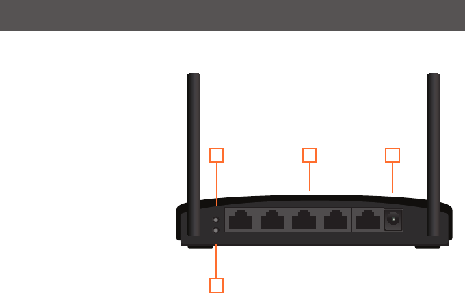
Product Overview
2 31
4
1. WPS Button
Push and hold the WPS button for
5~10 seconds to enable the WPS
feature.
2. Ethernet Port
The Ethernet port allows a LAN
connection through Cat 5 cables.
Supports auto-sensing at 10/100M
speed, half/ full duplex.
3. AC Power
AC Power Adapter
4. Reset Button
Push and hold the reset button for
5~10 seconds to reset the Wi-Fi
Hub to factory default setting
7
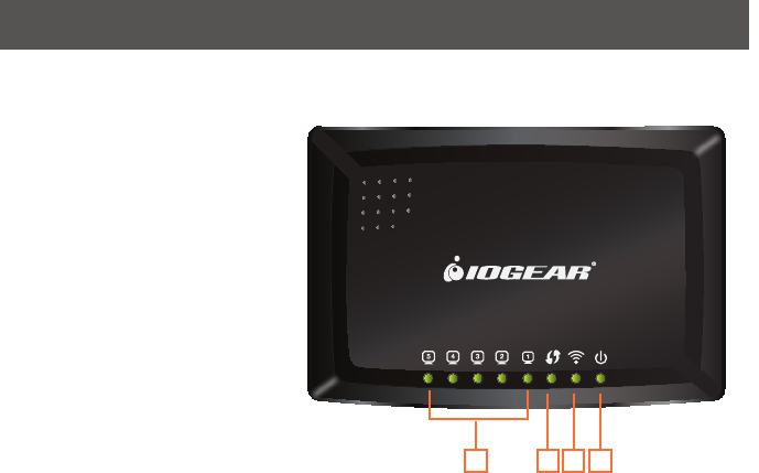
LED Indicator State Description
12 3 4
1. LAN LED
Flashing - Data is transmitting or
receiving on the LAN interface.
On - Port linked.
Off – No link.
2. WPS LED
Flashing - The WPS feature is enabled
and in use.
Off - The WPS feature is not in use.
3. WLAN LED
Flashing - WLAN is transmitting or
receiving data.
Off - WLAN is off
4. Power LED
On - Power on.
Off - Power off.

8
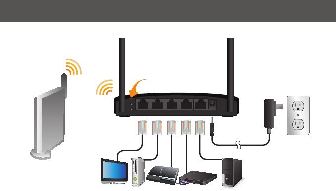
Installation
Wireless Setup with WPS
Step 1: Power on your Universal WiFi Hub using
either of these methods:
•ConnecttheACAdaptercabletoadevice.Make
sure that the device where you connect the AC
Adapter cable is powered on.
•ConnecttheWiFiHubtoanelectricaloutletwith
the included power adapter.
Note: It will take about 50 seconds to complete the
boot-up sequence. When complete, PWR (power)
LED will be active, and the WLAN Activity LED will
be blinking to show the WLAN interface is enabled.
Step 2: Use the included RJ-45 Ethernet cable to
connect the WiFi Hub with your device such as
Blu-ray player, HDTV, or game console.
Step 3: Refer to your wireless router’s user manual
to enable the WPS function, then press “WPS”
button on the back of WiFi Hub.
Your installation is complete. If asked for the type
of connection, make sure “WIRED” is selected on
your device.
WPS
Reset PWR51 2 3 4
9
Step 1
Step 3
Step 2
10
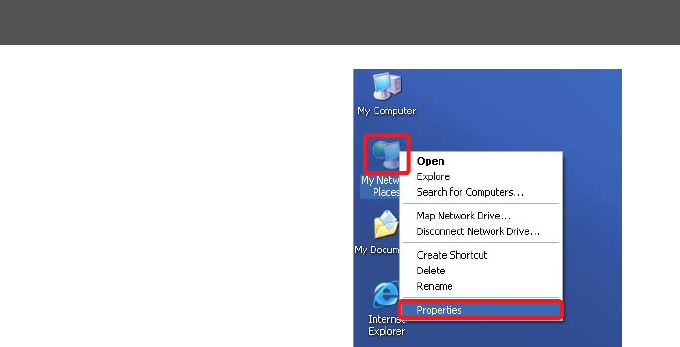
Installation without WPS - Windows XP
Step 1: Turn off your computer’s wireless
connection (if applicable) and disconnect the
Ethernet cable currently connect to your computer
(if applicable).
Step 2: Use the included RJ-45 Ethernet cable to
connect the WiFi Hub with your computer.
Step 3: Set your computer with a static IP address.
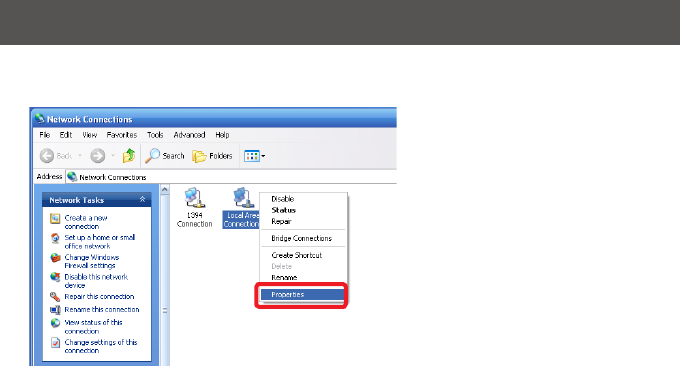
a. Right click on “My Network Places” and select
“Properties”.
11
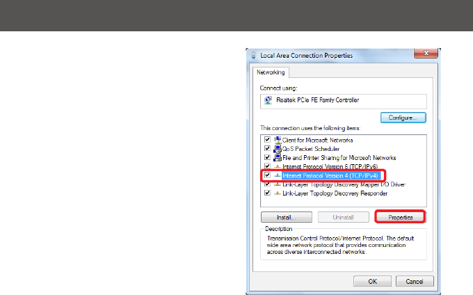
b. Next, right click on “Local Area Connection”
and select “Properties”.
12
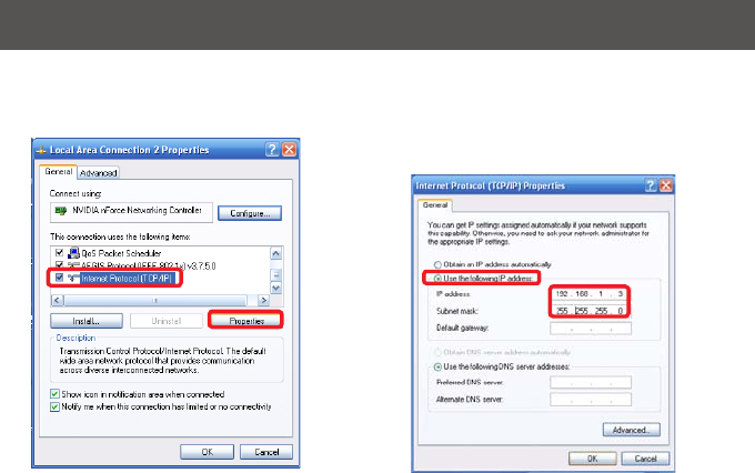
c. Select “Internet Protocol (TCP/IP)” then
select “Properties”.
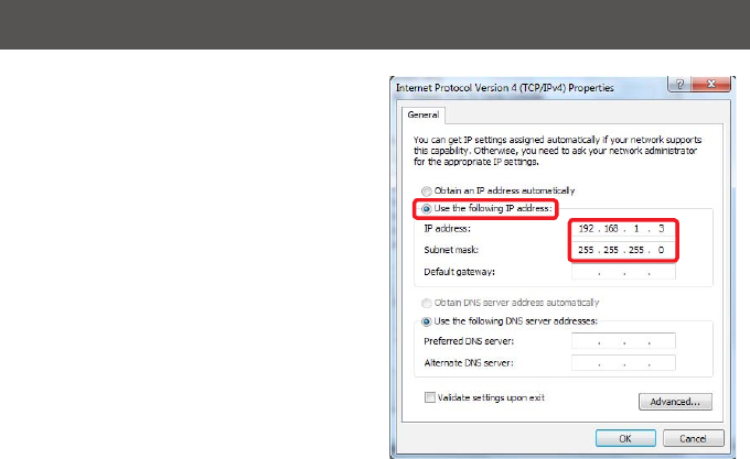
D. Select “Use the following IP address” and
enter 192.168.1.3 in the IP address section.
Next enter 255.255.255.0 in the Subnet Mask.
Click OK.

13
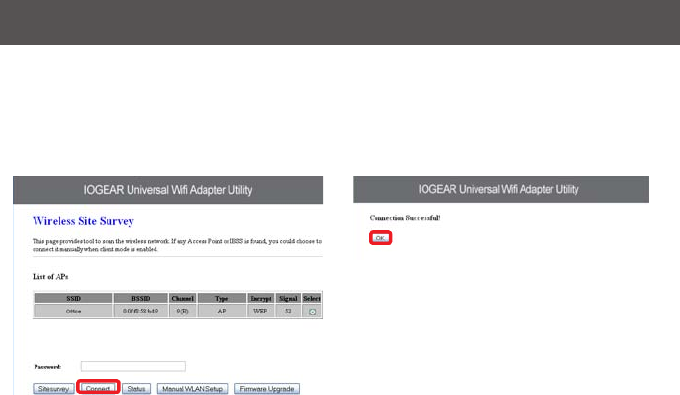
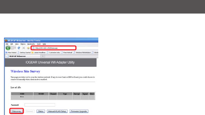
Step 4: Open your web browser and enter
192.168.1.252.Thiswillbringuptheconguration
utility. Click “Site Survey” to scan for your wireless
network.
14
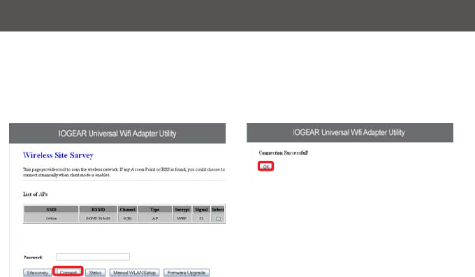
Step 5: Select the AP you want to connect to and enter the password if the network is secured. Click
the “Connect” button to establish the connection.
If your network security settings are set to not broadcast your SSID, then you will need to manually set
up the SSID and the wireless security (WEP or WPA). (Please see Page. 37)

15
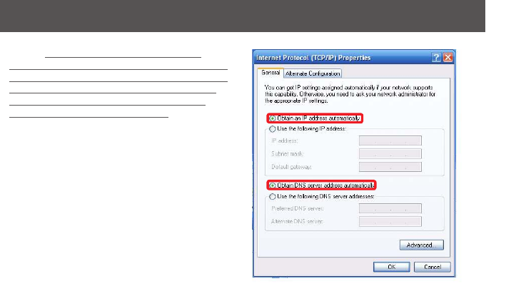
Step 6: Close your browser and change the
network settings on your computer back to DHCP
(Obtain an IP address Automatically & Obtain DNS
server address automatically). Refer to steps 3a
through 3d. Also do not forget to enable your
wireless connection if you disabled it.
Step 7: Disconnect the Ethernet cable from your
computer.
Step 8: Use the included RJ-45 Ethernet cable to
connect the WiFi Hub with your device such as a
Blu-Ray player, HDTV, or game colsole.
Step 9: Power on your Hub using the AC adapter.
The installation is complete. Your device is now
wireless. If the device asks for the type of internet
connection, make sure “WIRED” is selected.
16
Installation without WPS - Windows Vista
Step 1: Turn off your computer’s wireless connection (if applicable) and disconnect the Ethernet cable cur-
rently connect to your computer (if applicable).
Step 2: Use the included RJ-45 Ethernet cable to connect the WiFi Hub with your computer.
Step 3: Set your computer with a static IP address.
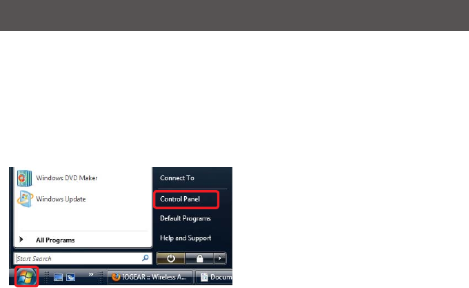
a. Click the start button, the click on Control Panel.
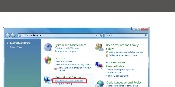
17
b. Under Network and Internet, click “View network status and tasks”.
18
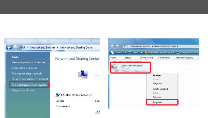
c. Under Tasks in the left pane, click “Manage
network connections”.
d. Next, right click on “Local Area Connection”
and click “Properties”.
19
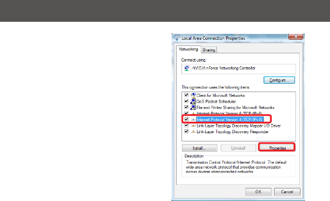
e. Next, select “Internet Protocol Version 4
(TCP/IPv4)” and click “Properties”
20
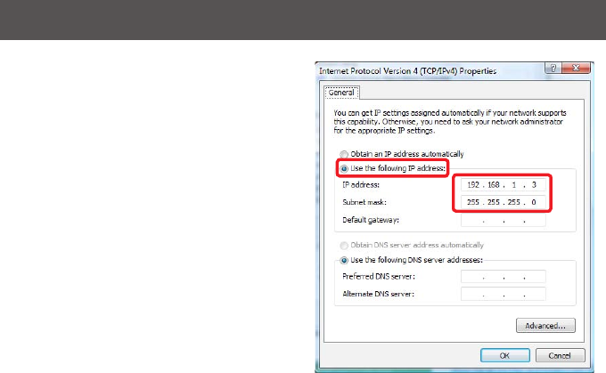
f. Select “Use the following IP address” and
enter 192.168.1.3 in the IP address section.
Next enter 255.255.255.0 in the Subnet Mask.
Click OK.
21
Step 4: Open your web browser and enter 192.168.1.252.Thiswillbringupthecongurationutility.Click
“Site Survey” to scan for your wireless network.

22
Step 5: Select the AP you want to connect to and enter the password if the network is secured. Click the
“Connect” button to establish the connection.
If your network security settings are set to not broadcast your SSID, then you will need to manually set up
the SSID and the wireless security (WEP or WPA). (Please see Page. 37)

23
Step 6: Close your browser and change the
network settings on your computer back to DHCP
(Obtain an IP address Automatically & Obtain DNS
server address automatically). Refer to steps 3a
through 3d. Also do not forget to enable your
wireless connection if you disabled it.
Step 7: Disconnect the Ethernet cable from your
computer.
Step 8: Use the included RJ-45 Ethernet cable to
connect the WiFi Hub with your device such as a
Blu-Ray player, HDTV, or game colsole.
Step 9: Power on your Hub using the AC adapter.
The installation is complete. Your device is now
wireless. If the device asks for the type of internet
connection, make sure “WIRED” is selected.
24
Installation without WPS - Windows 7
Step 1: Turn off your computer’s wireless connection (if applicable) and disconnect the Ethernet cable cur-
rently connect to your computer (if applicable).
Step 2: Use the included RJ-45 Ethernet cable to connect the WiFi Hub with your computer.
Step 3: Set your computer with a static IP address.
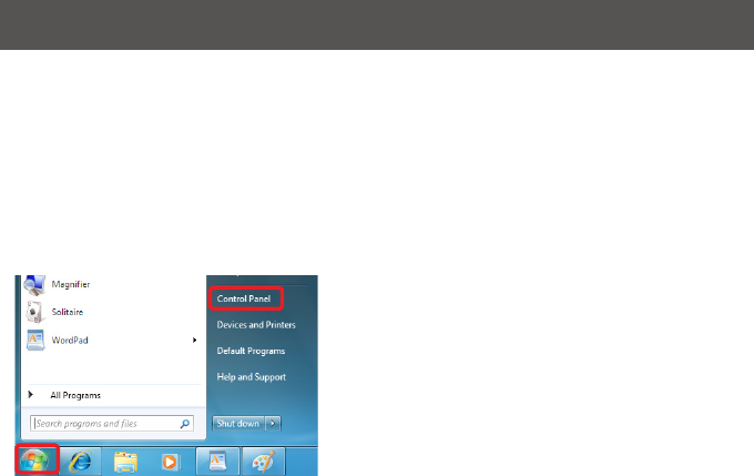
a. Click the start button, the click on Control Panel.
25
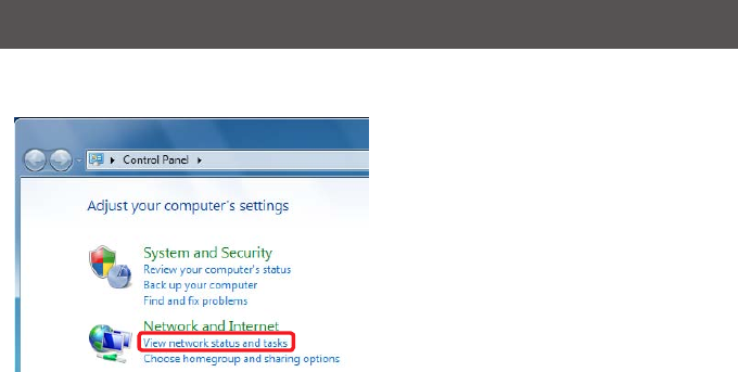
b. Under Network and Internet, click “View network status and tasks”.
26
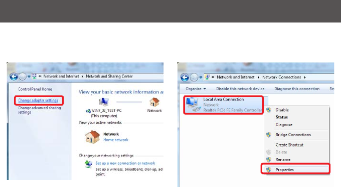
c. Under Tasks in the left pane, click “Change
Adapter Settings”.
d. Next, right click on “Local Area Connection”
and click “Properties”.
27
e. Next, select “Internet Protocol Version 4
(TCP/IPv4)” and click “Properties”
28
f. Select “Use the following IP address” and
enter 192.168.1.3 in the IP address section. Next
enter 255.255.255.0 in the Subnet Mask. Click
OK.

29
Step 4: Open your web browser and enter
192.168.1.252.Thiswillbringuptheconguration
utility. Click “Site Survey” to scan for your wireless
network.
30
Step 5: Select the AP you want to connect and enter the password if the network is secured. Click “Con-
nect” button to establish the connection.
If your network security settings are set to not broadcast your SSID, then you will need to manually set up
the SSID and the wireless security (WEP or WPA). (Please see Page. 37)
31
Step 6: Close your browser and change the
network settings on your computer back to DHCP
(Obtain an IP address Automatically & Obtain DNS
server address automatically). Refer to steps 3a
through 3d. Also do not forget to enable your
wireless connection if you disabled it.
Step 7: Disconnect the Ethernet cable from your
computer.
Step 8: Use the included RJ-45 Ethernet cable to
connect the WiFi Hub with your device such as a
Blu-Ray player, HDTV, or game colsole.
Step 9: Power on your Hub using the AC adapter.
The installation is complete. Your device is now
wireless. If the device asks for the type of internet
connection, make sure “WIRED” is selected.
32
Installation without WPS - Mac
Step 1: Turn off your computer’s wireless con-
nection (if applicable) and disconnect the Ethernet
cable currently connect to your computer (if ap-
plicable).
Step 2: Use the included RJ-45 Ethernet cable to
connect the WiFi Hub with your computer.
Step 3: Set your computer with a static IP address.
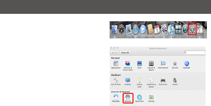
a. Open system preferences and select “Network”.
33
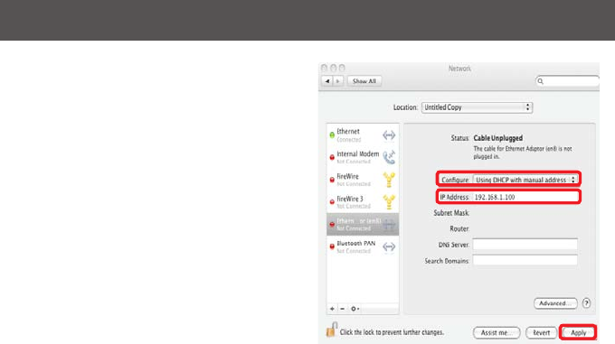
b. Select your Ethernet connection in the left pane.
NextchangeconguretoManualandenter
IP address 192.168.1.100 and Subnet Mask
255.255.255.0. Remove any entries in the
Router and DNS boxes then click Apply.

34
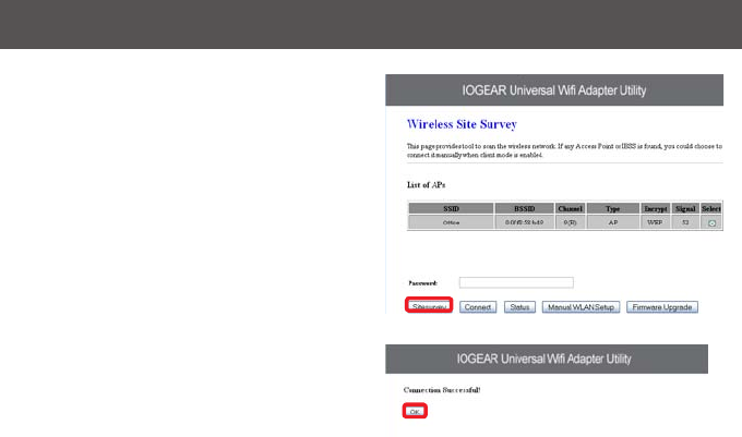
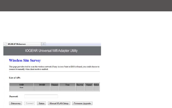
Step 4: Open your web browser and enter
192.168.1.252.Thiswillbringuptheconguration
utility. Click “Site Survey” to scan for your wireless
network.
35
Step 5: Select the AP you want to connect to and
enter the password if the network is secured. Click
the “Connect” button to establish the connection.
If your network security settings are set to not
broadcast your SSID, then you will need to
manually set up the SSID and the wireless security
(WEP or WPA). (Please see Page. 37)

36
Step 6: Close your browser and change the network settings on your computer back to DHCP. Refer to
steps 3a through 3b.
Step 7: Disconnect the Ethernet cable from your computer.
Step 8: Use the included RJ-45 Ethernet cable to connect the WiFi Hub with your device such as a
Blu-Ray player, HDTV, or game colsole.
Step 9: Power on your Hub using the AC adapter.
The installation is complete. Your device is now wireless. If the device asks for the type of internet
connection, make sure “WIRED” is selected.
37
Manual Set Up
If your network security settings are set to not broadcast your SSID, then you will need to manually
set up the SSID and the wireless security (WEP or WPA).
Step 1: Click “Manual WLAN Setup” to start the Setup Wizard
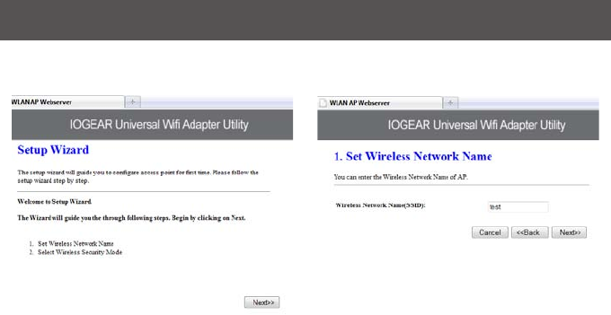
38
Step 2: Click “Next” Step 3: Enter your networks SSID and click “Next”
39
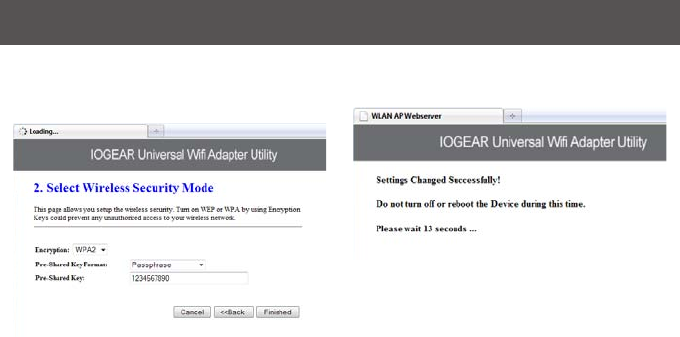
Step 4: Enter your encryption information and
click “Finished”
Step 5: The Universal Wi-Fi Hub will now reboot.

40
Step 6: Close your browser and change the network settings on your computer back to DHCP (Obtain an
IP address Automatically & Obtain DNS server address automatically). Also do not forget to enable your
wireless connection if you disabled it.
Step 7: Disconnect the Ethernet cable from your computer.
Step 8: Use the included RJ-45 Ethernet cable to connect the WiFi Hub with your device such as a Blu-
Ray player, HDTV, or game colsole.
Step 9: Power on your Hub using the AC adapter.
The installation is complete. Your device is now wireless. If the device asks for the type of internet
connection, make sure “WIRED” is selected.

41
Firmware Upgrade
Note:Ifarmwareupdateisavailable,itwillbe
posted on iogear.com. Please check
http://www.iogear.com/support/dm/
Step 1: Turn off your computer’s wireless
connection (if applicable) and disconnect the
Ethernet cable currently connect to your computer
(if applicable).
Step 2: Use the included RJ-45 Ethernet cable to
connect the WiFi Hub with your computer.
Step 3: Set your computer with a static IP address.
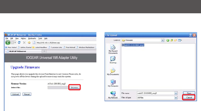
Step 4: Open your web browser and enter
192.168.1.252.Thiswillbringuptheconguration
utility. Click the “Firmware Upgrade” button.
42
Step 5: Click “Browse”andlocatedyourrmwarele,selectit,andclick“Open”.
43
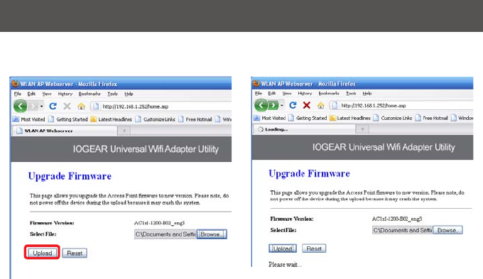
Step 6: Click “Upload”tostartthermwareupgradeprocess.
44
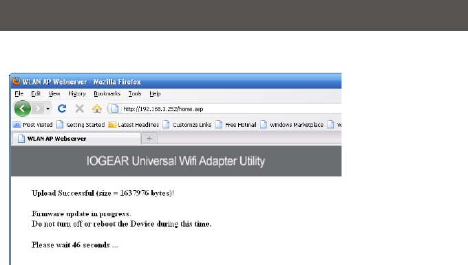
Firmware update complete. Wait for the device to reboot before disconnecting.
45
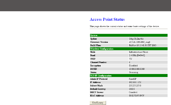
Oncethedeviceisnishedrebooting,youwillseea
statusscreen.Checkyoursettings.Afterarmware
upgrade,theUniversalWiHubmayresetback
to factory settings and need to be set up for your
network again.

46
Federal Communications Commission (FCC) Statement
Federal Communications Commission (FCC) Statement
15.21
You are cautioned that changes or modifications not expressly approved by the part responsible for compliance
could void the user’s authority to operate the equipment.
15.105(b)
This equipment has been tested and found to comply with the limits for a Class B digital device, pursuant to part 15 of
the FCC rules. These limits are designed to provide reasonable protection against harmful interference in a residential
installation. This equipment generates, uses and can radiate radio frequency energy and, if not installed and used in
accordance with the instructions, may cause harmful interference to radio communications. However, there is no
guarantee that interference will not occur in a particular installation. If this equipment does cause harmful interference
to radio or television reception, which can be determined by turning the equipment off and on, the user is encouraged
to try to correct the interference by one or more of the following measures:
-Reorient or relocate the receiving antenna.
-Increase the separation between the equipment and receiver.
-Connect the equipment into an outlet on a circuit different from that to which the receiver is connected.
-Consult the dealer or an experienced radio/TV technician for help.
This device complies with Part 15 of the FCC Rules. Operation is subject to the following two conditions:
1) this device may not cause harmful interference, and
2) this device must accept any interference received, including interference that may cause undesired operation of the device.
FCC RF Radiation Exposure Statement:
1.This Transmitter must not be co-located or operating in conjunction with any other antenna or transmitter.
2.This equipment complies with FCC RF radiation exposure limits set forth for an uncontrolled environment.
This equipment should be installed and operated with a minimum distance of 20 centimeters between the radiator
and your body.

47
This device has been tested and found to comply with the following European Union directives: Electro-
magnetic Capability (89/336/EMC), Low Voltage (73/23/EEC) and R&TTED (1999/5/EC).
CE Compliance

48
The following contains information that relates to China.
SJ/T 11364-2006
部件名称
有毒有害物质或元素
铅 (Pb) 汞 (Hg) 镉(Cd) 六价 (Cr(VI)) 多溴联苯
(PBB)
多溴二苯醚
(PBDE)
电器部件 ● ○ ○ ○ ○ ○
机构部件 ○ ○ ○ ○ ○ ○
○:表示该有毒有害物质在该部件所有均质材料中的含量均在SJ/T 11363-2006规定的限量要求之下。
●:表示符合欧盟的豁免条款,但该有毒有害物质至少在该部件的某一均质材料中的含量超出
SJ/T 11363-2006的限量要求。
×:表示该有毒有害物质至少在该部件的某一均质材料中的含量超出SJ/T 11363-2006的限量要求。

49
IN NO EVENT SHALL THE DIRECT VENDOR’S LIABILITY FOR DIRECT, INDIRECT, SPECIAL,
INCIDENTAL OR CONSEQUENTIAL DAMAGES RESULTING FROM THE USE OF THE PRODUCT,
DISK, OR ITS DOCUMENTATION EXCEED THE PRICE PAID FOR THE PRODUCT.
The direct vendor makes no warranty or representation, expressed, implied, or statutory with respect to
the contents or use of this documentation, and especially disclaims its quality, performance,
merchantability,ortnessforanyparticularpurpose.Thedirectvendoralsoreservestherighttorevise
or update the device or documentation without obligation to notify any individual or entity of such
revisions, or updates. For further inquiries please contact IOGEAR.
WE’RE HERE TO HELP YOU!
NEED ASSISTANCE SETTING UP THIS PRODUCT?
Make sure you:
1. Use the live chat at www.iogear.com to try and solve any issues you may be having with the product
2. Visit the Tech Info Library/FAQ on www.iogear.com (under the Support tab)
3. Call the tech support line at 1(866) 946-4327 (U.S. only) or (949) 453-8782.
Limited Warranty

50
IOGEAR
19641 Da Vinci
Foothill Ranch, CA 92610
P 949.453.8782
F 949.453.8785
Visit us at: www.iogear.com
Contact
© 2011 IOGEAR® Part No. M1200
IOGEAR, the IOGEAR logo, are trademarks or registered trademarks of IOGEAR. Microsoft and Windows are registered trademarks of Microsoft
Corporation. All other brand and product names are trademarks or registered trademarks of their respective holders. IOGEAR makes no warranty of
any kind with regards to the information presented in this document. All information furnished here is for informational purposes only and is subject to
change without notice. IOGEAR assumes no responsibility for any inaccuracies or errors that may appear in this document.

51

© 2011 IOGEAR®
FUN
IOGEAR offers connectivity solutions that are innovative, fun, and stylish,
helping people enjoy daily life using our high technology products.
GREEN
IOGEAR is an environmentally conscious company that emphasizes the
importance of conserving natural resources. The use of our technology solutions
helps reduce electronic waste.
About Us
About Us
PART NO. M1200