ATI Automation 9105WNET Wireless Multi-Axis Force/Torque Transmitter User Manual 9620 05
ATI Industrial Automation Wireless Multi-Axis Force/Torque Transmitter 9620 05
UserManual.wiki
>
ATI Automation
>
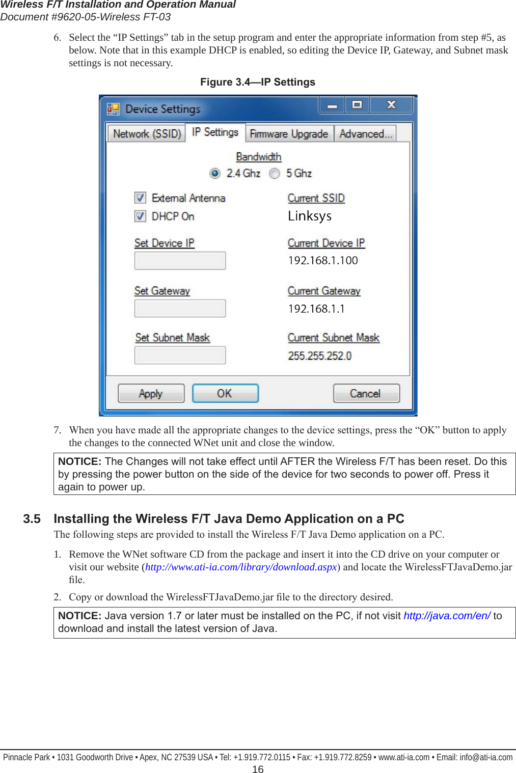
9105WNET User Manual
User Manual - 9620-05
Navigation menu
Upload a User Manual
Namespaces
Wiki Guide
HTML
PDF
Info
Views
User Manual
Discussion / Help
Navigation

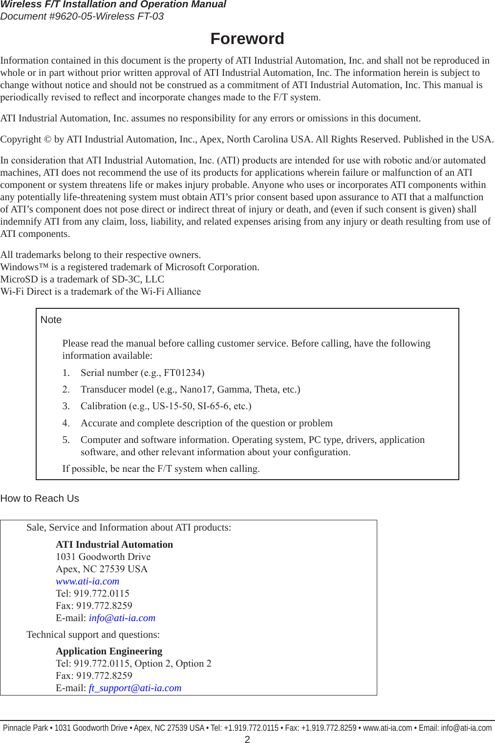


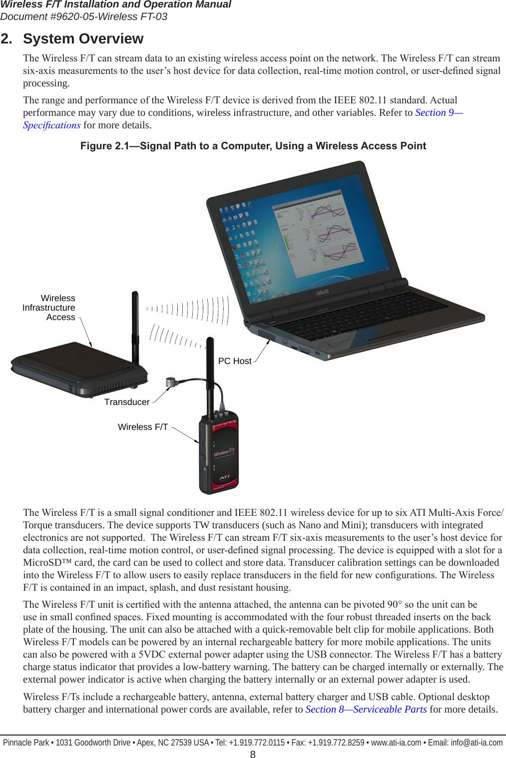
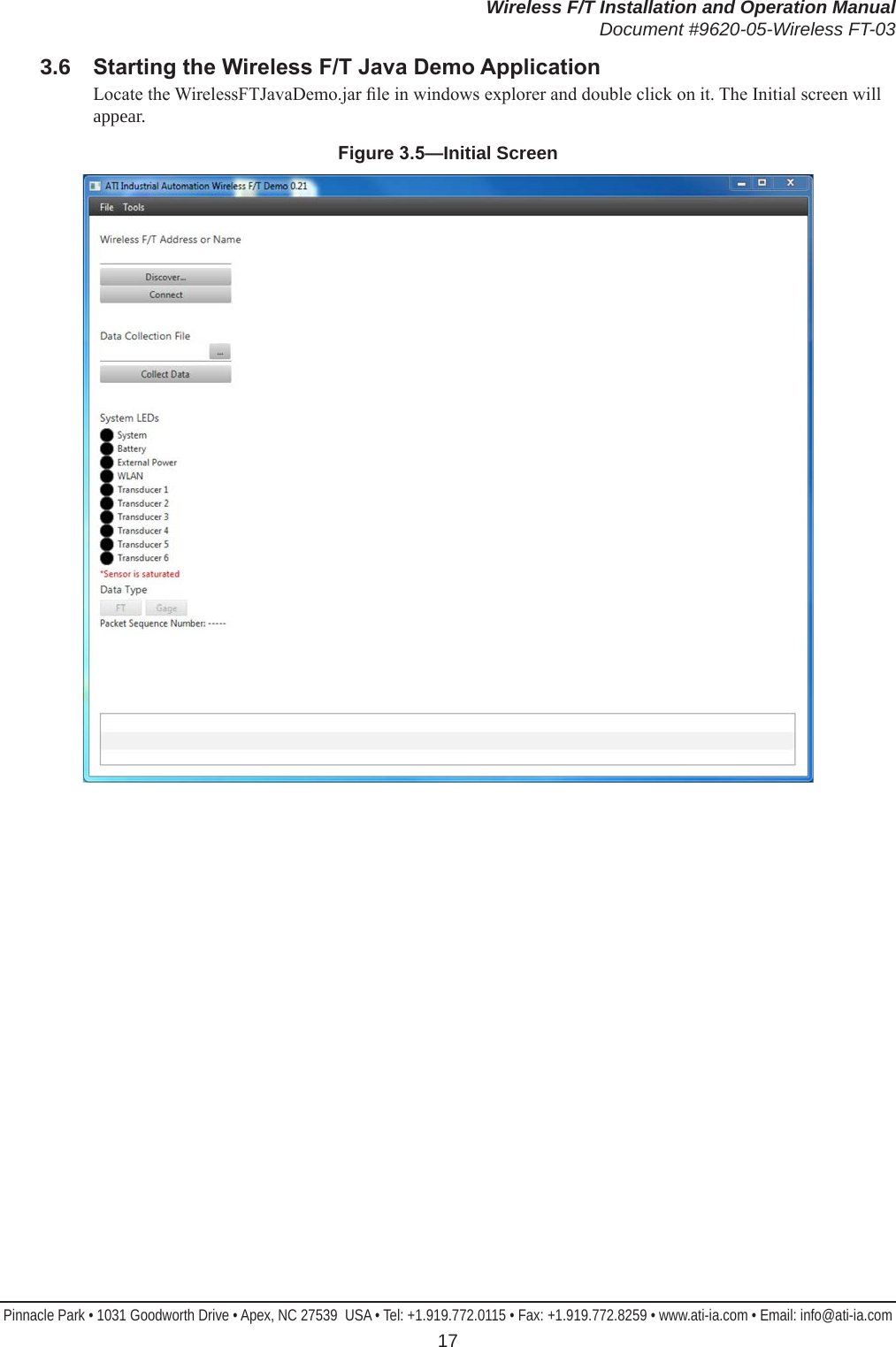
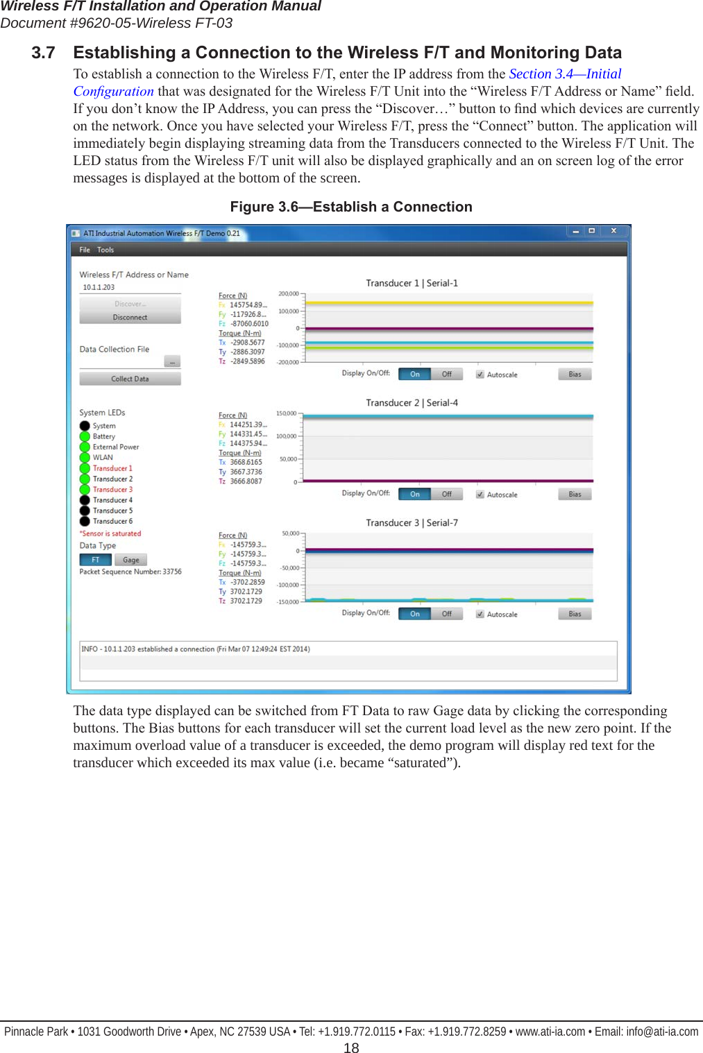
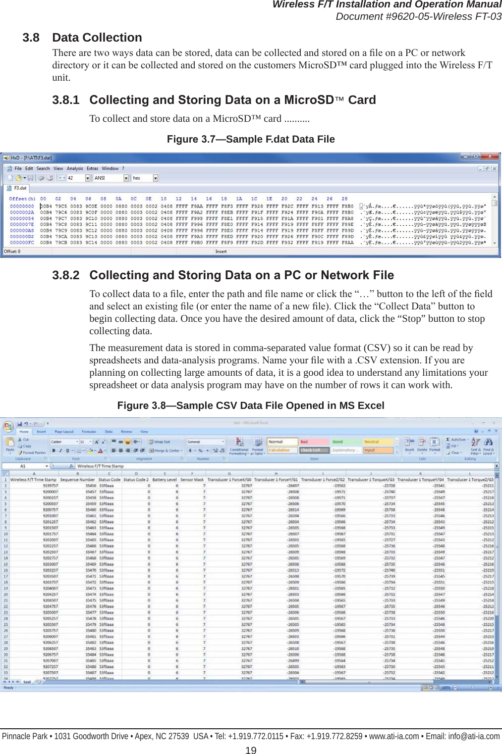
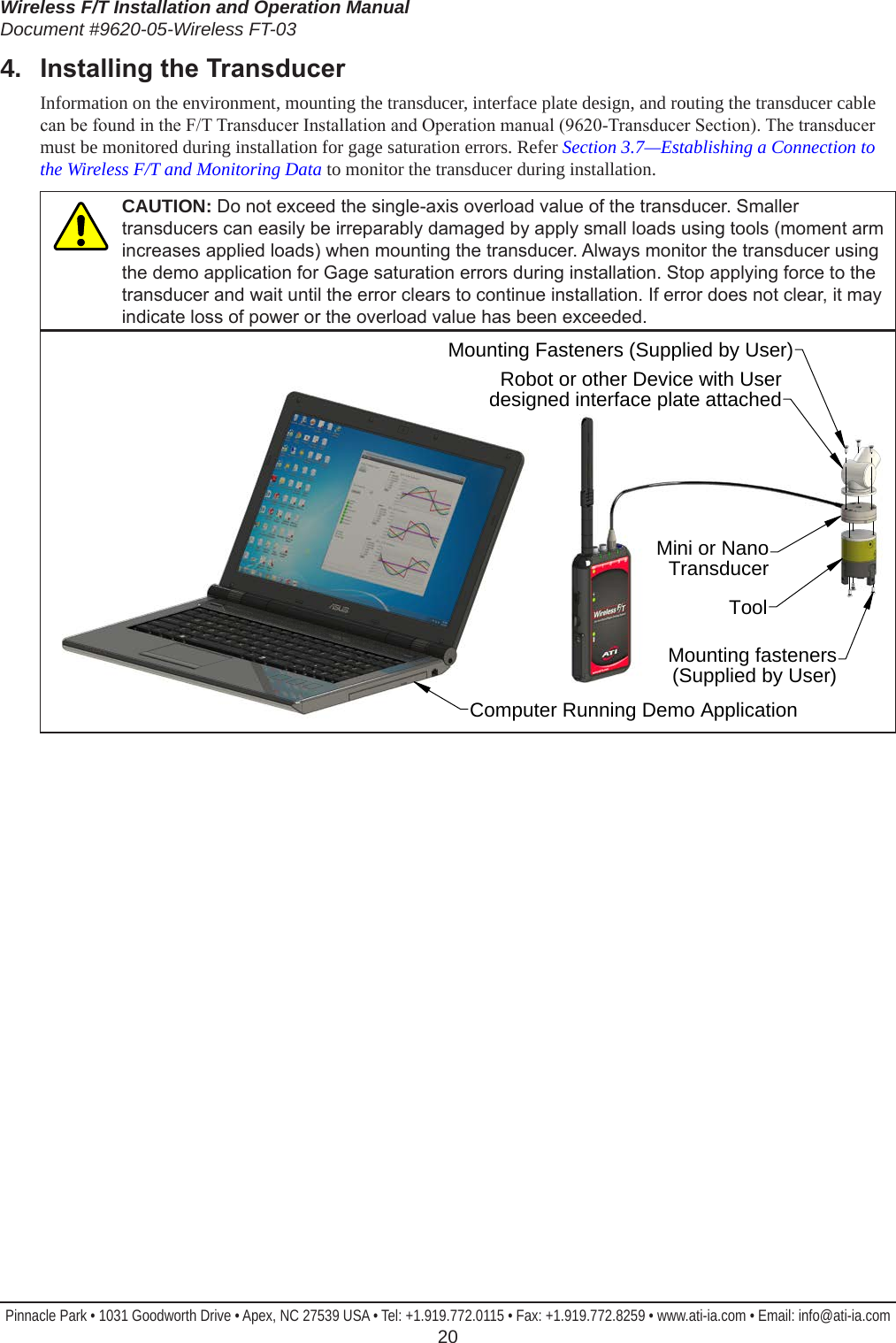
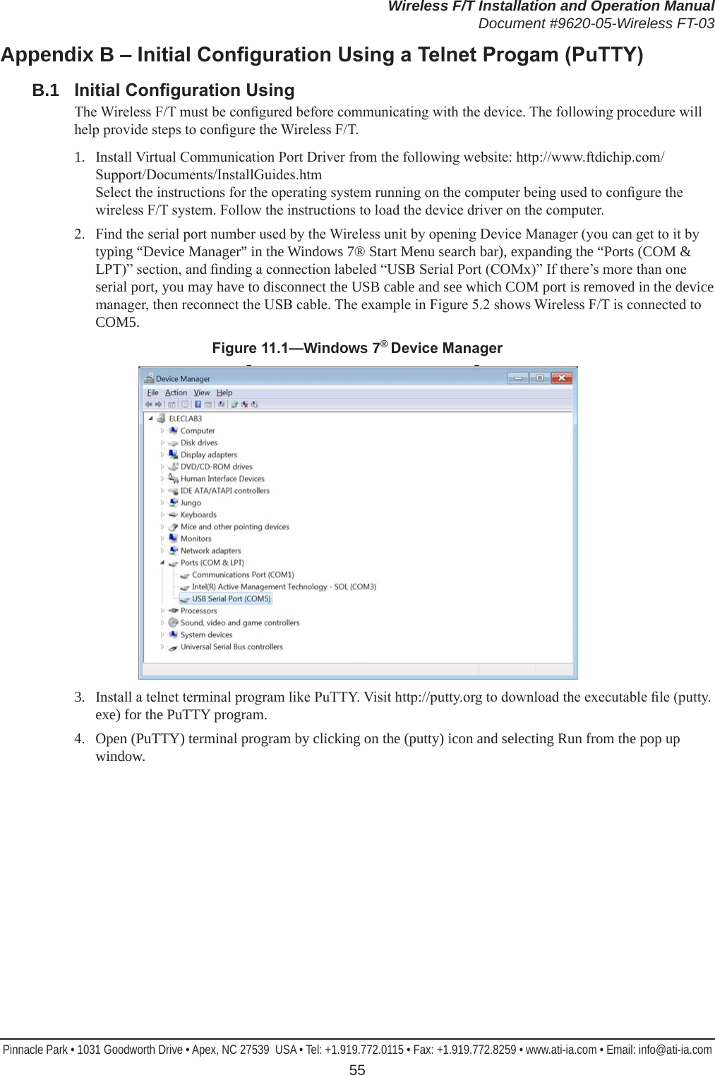
![Wireless F/T Installation and Operation ManualDocument #9620-05-Wireless FT-03Pinnacle Park • 1031 Goodworth Drive • Apex, NC 27539 USA • Tel: +1.919.772.0115 • Fax: +1.919.772.8259 • www.ati-ia.com • Email: info@ati-ia.com 215. Command InterfaceThe WNet unit must be installed, setup and congured prior to using any command interfaces. Refer to Section 3—Installation for Installation, setup, and conguration of the WNet unit. 5.1 Communication InterfacesThe Wireless F/T can be setup and congured using a text-based command prompt console interface.The Console Interface can be accessed two ways:• Commands can be sent over the USB Connection over the wireless connector as a virtual serial port• Telnet server listening on TCP Port 235.2 UPD InterfaceThe WNET unit listens on UDP port 49152 for commands. Any streaming UDP packets are sent to the current Destination IP address until a UDP command is received. When the WNET unit receives a UDP command from any IP address, the UDP packets are sent to whichever port the request came from.The UDP server uses binary format for commands and responses. All multi-byte values use big-endian, which is the same as network order. 5.3 UDP Command Format All UDP commands to the WNET unit have the following format:Table 5.1—UDP Command FormatField Name Format Length(bytes) Commentslength unsigned short 2 Total length of this message, including CRCsequence unsigned char 1 Sequence number. Used to identify missing messages.command unsigned char 1 Command numberpayload unsigned char(s) length - 6 Command operands (if any)crc unsigned short 2 See Appendix A – UDP Command CRC Calculation, for details This format can be rendered into C as:struct udp_RecvFrame_S{ unsigned short length; // Total length of this message unsigned char sequence; // sequence number of this message unsigned char command; // command number unsigned char parameters[0]; // command operands } __attribute__ ((__packed__));These commands are currently implemented:Table 5.2—Current Command ImplementationNumber Name Comments1 Start streaming Start streaming for either a xed or unlimited number of packets2 Stop streaming Stops streaming3 Set packet transmission rate Sets packet transmission rate. All transducers use the same rate.4 Ping Sends a no-payload Pong response back to the sender.](https://usermanual.wiki/ATI-Automation/9105WNET/User-Guide-2393866-Page-21.png)
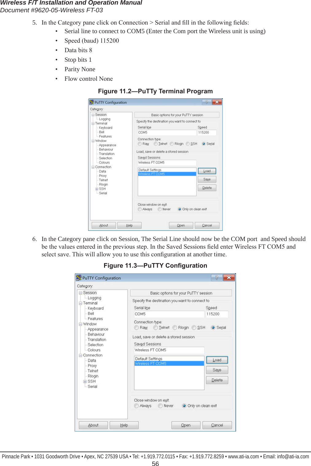
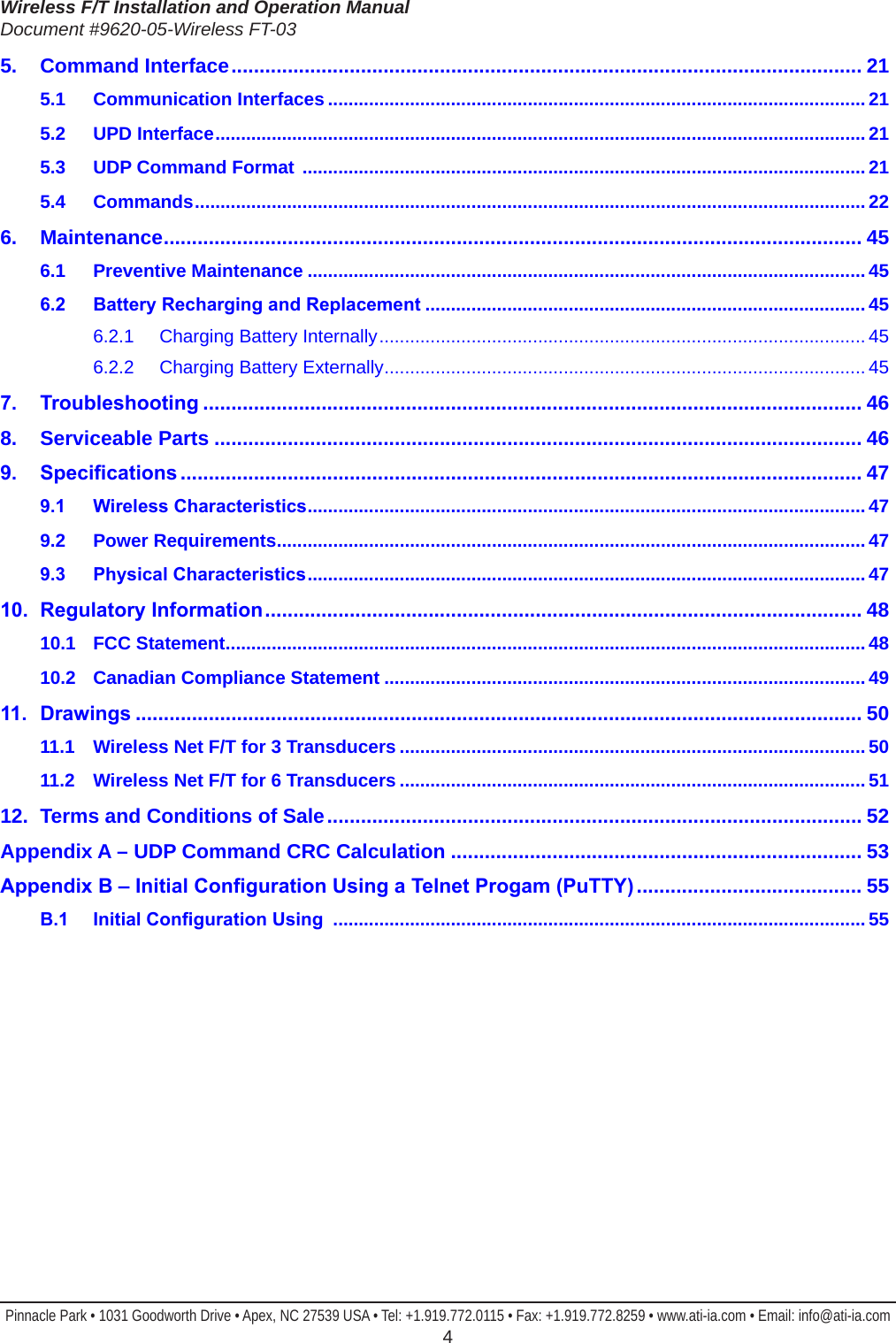
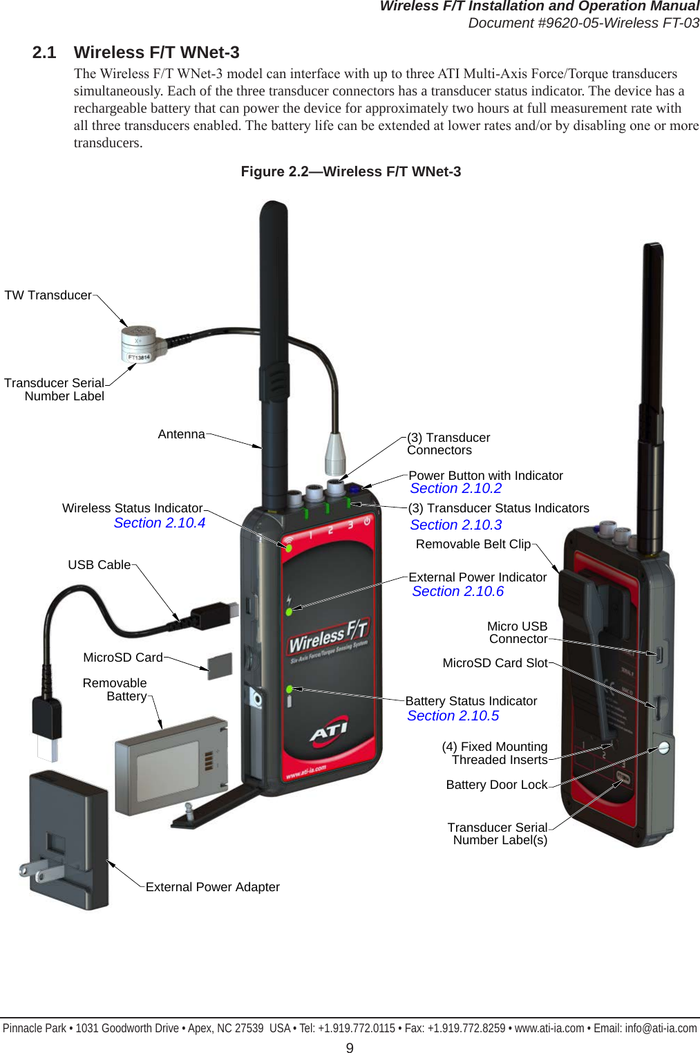
![Wireless F/T Installation and Operation ManualDocument #9620-05-Wireless FT-03Pinnacle Park • 1031 Goodworth Drive • Apex, NC 27539 USA • Tel: +1.919.772.0115 • Fax: +1.919.772.8259 • www.ati-ia.com • Email: info@ati-ia.com 225.4 CommandsThese commands are available to any user, including commands to enter authenticated user and technician user modes. All users can read any information about the system, including values that only authenticated or technician users can write to.H, HELP, or “?” These commands print a summary of the Console commands supported by the WNet unit.A [S] => ADC Single read (Analog Board) This command reads the ADC converters from the Analog Board one time, and prints the results. For example:Tr Ch ADC-Raw -- -- ------- 1 0 -12976 1 1 -25950 1 2 -31035 1 3 0 1 4 0 1 5 0 2 0 -12971 2 1 -25940 2 2 -31024 2 3 0 2 4 0 2 5 0 3 0 -12961 3 1 -25920 3 2 -31020 3 3 0 3 4 0 3 5 0AD => read all processor analog inputs This command reads the processor analog inputs (Digital Board) and prints the results. For example:Pin Voltage --- ------- PD7 2.037 PE2 2.407 PE3 2.409 PE4 2.237 PE5 2.233 PE6 2.141 Temperature 33*CADCBW [FULL | 1/4] => set ADC bandwidth This command selects the bandwidth for low-pass lter to either FULL or 1/4. Refer to the Selectable Low-Pass Filter section in the ADC data sheet for details. For ADC testing only.1/4 → 1/4 of bandwidth, uses an additional series resistor to further bandwidth limit the noise. Maximum throughput must also be reduced to ¼. FULL → full bandwidth](https://usermanual.wiki/ATI-Automation/9105WNET/User-Guide-2393866-Page-22.png)
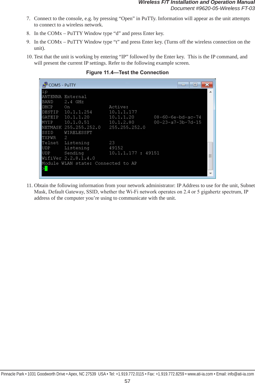
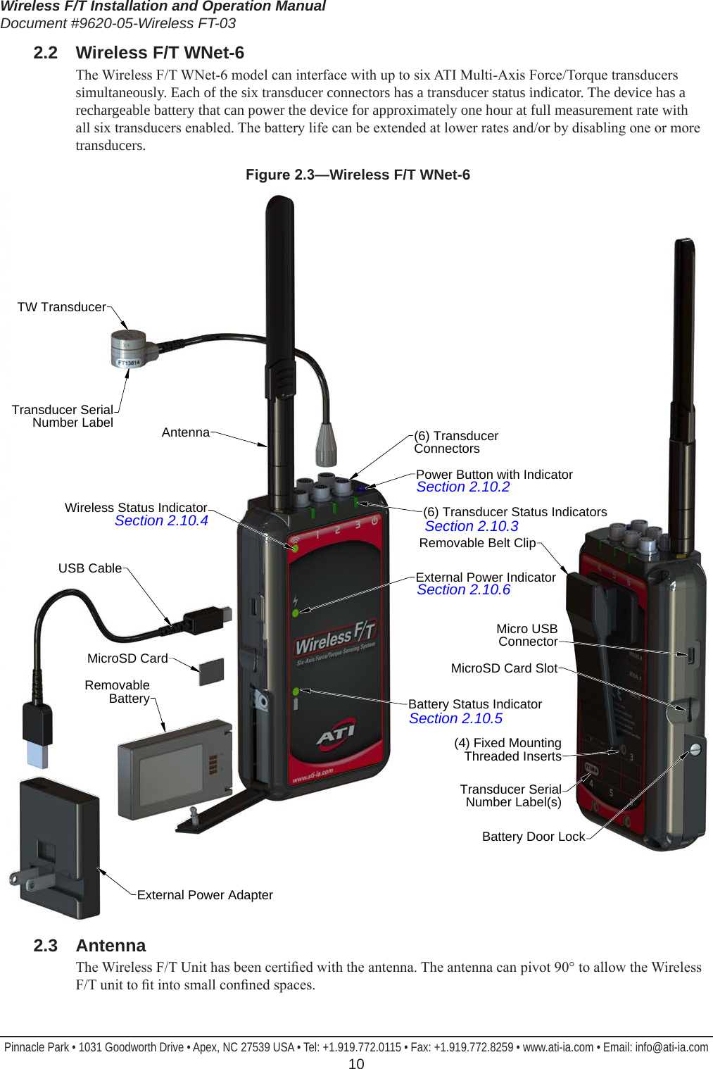
![Wireless F/T Installation and Operation ManualDocument #9620-05-Wireless FT-03Pinnacle Park • 1031 Goodworth Drive • Apex, NC 27539 USA • Tel: +1.919.772.0115 • Fax: +1.919.772.8259 • www.ati-ia.com • Email: info@ati-ia.com 23ADCDEL [1 -> 2000] => set minimum ADC conversion time in 12.5 nS units This command sets the conversion delay time for the ADCs on the Analog Board when samples are being read from the same physical ADC. Each count = 1 / 80,000,000 second = 12.5 nS. If the delay is too short, the analog measurements will have additional noise. If the delay is too long, time is wasted. Because sampling from multiple transducers is interleaved, this value usually matters only if you reading samples from a single Transducer. For ADC testing only.ADCINCC [0 -> 7] => set the ADC Input Channel CongurationThis command controls the input channel conguration, which consists of the selection of pseudo bipolar, pseudo differential, pairs, single-ended, or temperature sensor. Refer to the Input Congurations section of the ADC data sheet for details. Note that the rmware will automatically convert unipolar to bipolar as needed after each sample is read.0. Bipolar differential pairs; INx− referenced to VREF/2 ± 0.1 V. 1. “ 2. Bipolar; INx referenced to COM = VREF/2 ± 0.1 V. 3. Temperature sensor. 4. Unipolar differential pairs; INx− referenced to GND ± 0.1 V. 5. “ 6. Unipolar, INx referenced to COM = GND ± 0.1 V. 7. Unipolar, INx referenced to GND.ADCREF [0 -> 7] => set the ADC referenceThis command controls the selection of internal, external, external buffered, and enabling of the ADC on-chip temperature sensor. Refer to the Voltage Reference Output/Input section of the ADC data sheet for details. For ADC testing only.0. Internal reference, REF = 2.5 V output, temperature enabled. 1. Internal reference, REF = 4.096 V output, temperature enabled. 2. External reference, temperature enabled. 3. External reference, internal buffer, temperature enabled. 4. Undened 5. Undened 6. External reference, temperature disabled. 7. External reference, internal buffer, temperature disabled. ANALOG [ON | OFF] => Turns Analog power (ANALOG_SHDN) on or offThis command controls the ANALOG_SHDN bit to the Analog Board.ANTENNA [INT | EXT] => select internal or external antennaThis command selects whether the WLAN Module uses its internal antenna or an external antenna.AUTOZ => Auto Zero the Active Transducer/CalibrationThis command auto zeros the offset settings for the active Transducer and Calibration. BAND [2.4 | 5] => select 2.4 or 5 GHz BandThis command selects whether the WLAN Module uses the 2.4 GHz or the 5 GHz band.](https://usermanual.wiki/ATI-Automation/9105WNET/User-Guide-2393866-Page-23.png)
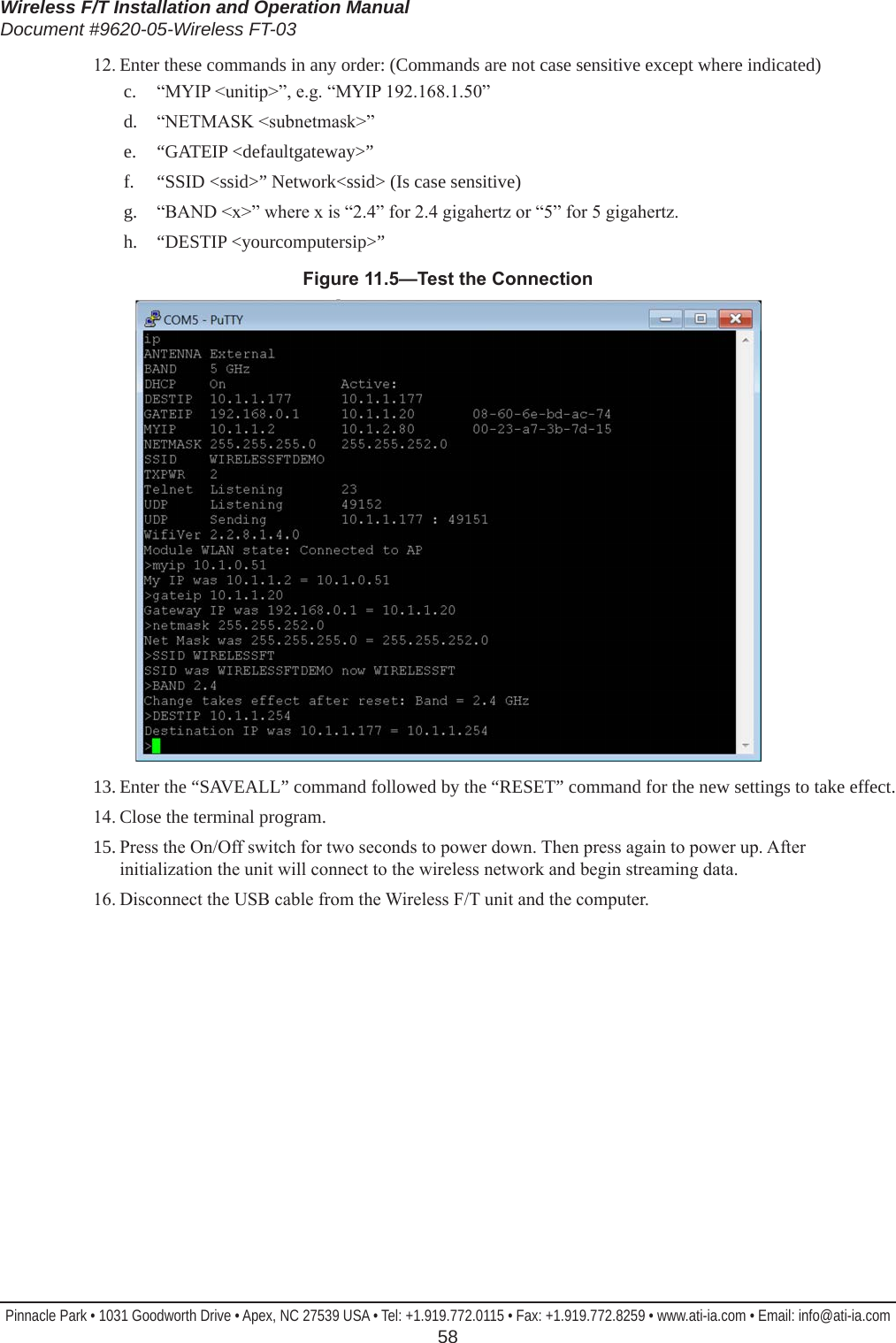
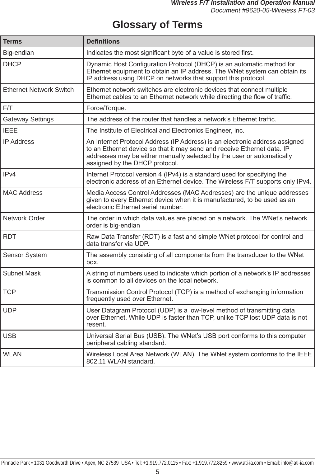
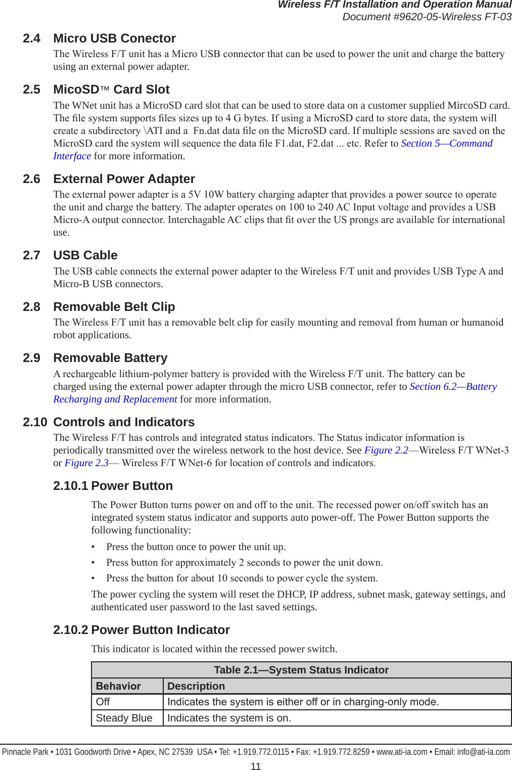
![Wireless F/T Installation and Operation ManualDocument #9620-05-Wireless FT-03Pinnacle Park • 1031 Goodworth Drive • Apex, NC 27539 USA • Tel: +1.919.772.0115 • Fax: +1.919.772.8259 • www.ati-ia.com • Email: info@ati-ia.com 24BAT [ON | OFF | seconds] => Battery log on, off, toggle, or number of secondsThis command turns a battery status log on and off. This log is used for testing the operation of the battery, the Battery Charger, and the Gas Gage. A log entry is generated once per second. The log records the following data items:a. day and time since last system restartb. charging voltage, as measured by the processor (at VPROG = PE3)c. battery voltage, as measured by the Gas Gauge (at SENSE-)d. Gas Gage Accumulated Charge Register (Ah)e. USB power present ag (yes or no)f. USB Battery Charger Detect (yes or no)g. generated battery level (0 to 10)h. Basis of the battery charge estimate method, voltage or currenti. Battery Charger status messagej. USB current limit USBILIM (mA)k. battery temperature (°C)l. CPU temperature (°C)m. Gas Gauge temperature (°C)n. ADC temperature for each powered Transducer (°C). Day-Time VPROG GGVolt Charge:Ah USBPwr USBBCD BatLvl Based BatteryChargerStatus USBILIM Batt*C CPU*C GG*C T4*C T5*C T6*C -------- ----- ------ --------- ------ ------ ------ ----- -------------------- ------- ------ ----- ---- ---- ---- ---- 0-18:42:43 0.000 3.806 1.443 No No 6 Volt ChargerOff 100 -19.0 39.8 37.5 25.0 24.8 27.2 0-18:42:44 0.000 3.806 1.443 No No 6 Volt ChargerOff 100 -19.0 39.8 37.5 25.1 24.7 27.2 0-18:42:45 0.000 3.806 1.443 No No 6 Volt ChargerOff 100 -19.0 39.9 37.5 25.1 24.7 27.2 0-18:42:46 0.000 3.806 1.443 No No 6 Volt ChargerOff 100 -19.0 39.9 37.5 24.9 24.7 27.2 0-18:42:47 0.000 3.802 1.443 No No 6 Volt ChargerOff 100 -19.0 39.9 37.5 25.0 24.7 27.2 0-18:42:48 0.000 3.802 1.443 No No 6 Volt ChargerOff 100 -19.0 39.9 37.5 24.9 24.7 27.2](https://usermanual.wiki/ATI-Automation/9105WNET/User-Guide-2393866-Page-24.png)
![Wireless F/T Installation and Operation ManualDocument #9620-05-Wireless FT-03Pinnacle Park • 1031 Goodworth Drive • Apex, NC 27539 USA • Tel: +1.919.772.0115 • Fax: +1.919.772.8259 • www.ati-ia.com • Email: info@ati-ia.com 25BC => print all Battery Charger registersThis command prints all Battery Charger registers in a decoded format. For example:BC: 0 = 60 DISABLE_INPUT_UVCL = Enabled EN_BAT_CONDITIONER = Enabled > 60*C LOCKOUT_ID_PIN = Autonomous Start-up Disabled USBILIM = 100 mA max BC: 1 = 20 PRIORITY = Wall Input Prioritized TIMER = 8 Hr or C/x indication WALLILIM = 100 mA max BC: 2 = fe ICHARGE = 100 % => 2238 mA with RPROG = 536 Ohms CXSET = 2 % => 44 mA VFLOAT = 4.20 V BC: 3 = 03 CHARGER_STATUS = Charger Off ID_PIN_DETECT = No Detection: We are USB OTG-B peripheral OTG_ENABLED = Step-Up Switching Regulator Inactive NTCSTAT = too cold: < 0*C LOWBAT = not meaningful BC: 4 = 00 EXT_PWR_GOOD = Battery Power Only USBSNS_GOOD = Voltage Invalid WALLSNS_GOOD = Voltage Invalid AT_INPUT_ILIM = Input Current Limit Inactive INPUT_UVCL_ACTIVE = Input UVCL Inactive OVP_ACTIVE = No Fault OTG_FAULT = No Fault BAD_CELL = No Fault BC: 5 = ff NTCVAL Temperature = 127 => -19*C NTC_WARNING = Too Warm or Too Cold to Charge BC: 6 = 00 ENABLE_CHARGER_INT = Disabled ENABLE_FAULT_INT = Disabled ENABLE_EXTPWR_INT = Disabled ENABLE_OTG_INT = Disabled ENABLE_AT_ILIM_INT = Disabled ENABLE_INPUT_UVCL_INT= Disabled REQUEST_OTG = Step-Up Voltage Regulator Automatic or DisabledBC [reg 0 -> 7] [hex byte] => write a Battery Charger registerThis command allows you to modify any writable Battery Charger register.BIAS [* | Transducer 1 -> 6] [OFF] => Set Bias on selected TransducerThis command allows you to set (or turn off) the bias on any or all Transducers.BRIGHT [0 -> 100%] => Set Analog Board LED brightnessThis command sets the brightness level of all LEDs on the Analog Board as a group. Brightness ranges from 0% to 100%.C => Exit Continuous ModeThe continuous mode commands are provided as a test mode for the Analog Board. This command exits the continuous mode.C [A] [channels 012345678 any combination ordered list]This command will cause the ADC input from the selected channels (for the Active Transducer) to be printed continuously as fast as possible in the order requested.C [D] [DAC 0 -> 7]This command causes the selected DAC (for the Active Transducer) to be written continuously.](https://usermanual.wiki/ATI-Automation/9105WNET/User-Guide-2393866-Page-25.png)
![Wireless F/T Installation and Operation ManualDocument #9620-05-Wireless FT-03Pinnacle Park • 1031 Goodworth Drive • Apex, NC 27539 USA • Tel: +1.919.772.0115 • Fax: +1.919.772.8259 • www.ati-ia.com • Email: info@ati-ia.com 26C [E] [EEPOT 0 -> 5]This command causes the selected EEPOT output (for the Active Transducer) to be written continuously.CAL => View Active Transducer/CalibrationThis command allows you to view the Calibration Matrix for the Active Transducer and Calibration. This includes all of its associated parameters. For example, in a test system this command printed the following report:Tr Cal Gain Offset Row G0 G1 G2 G3 G4 G5 Properties -- --- ---- ------ --- -- -- -- -- -- -- ---------- 1 0 0 32768 0 Fx 1 0 0 0 0 0 Serial: Serial-1 1 0 0 32768 1 Fy 0 1 0 0 0 0 Date: 1970/01/01 1 0 0 32768 2 Fz 0 0 1 0 0 0 Part: Part-1 1 0 0 32768 3 Tx 0 0 0 1 0 0 Force: 12 counts/N 1 0 0 32768 4 Ty 0 0 0 0 1 0 Torque: 34 counts/N 1 0 0 32768 5 Tz 0 0 0 0 0 1 Mult: OFF 1 0 MaxRatings: 1 0 0 0 0 0 0 0CAL [MATRIX] [Row: 0 -> 5] [Gage: 0 -> 5] [oat-values] => Change Active Matrix element(s)This command allows you to modify a multiple elements of the active calibration matrix. You can initialize an entire matrix by typing CAL MAT 0 0 followed by 36 values. Array overow is checked so that you cannot exceed the limits of the matrix.CAL [GAIN ] [* | Row: 0 -> 5] [0 -> 1023] => Change Active gainThis command allows you to set the gain for any or all of the 6 strain gages. This command operates on the Active Transducer and Active Calibration.CAL [OFFSET] [* | Row: 0 -> 7] [0 -> 65535] => Change Active offsetThis command allows you to set the offset for any or all of the 6 strain gages, and also the two unused channels 6 and 7. This command operates on the Active Transducer and Active Calibration.CAL [MAX] [Row: 0 -> 5] [oat-value] => Set Max Rating valueThis command allows you to set any of the 6 oating-point Max Rating values.CAL [SERIAL] [10-character string] => Change Active serial numberThis command allows you to set the serial number associated with the active calibration.CAL [DATE] [12-character string] => Change Active dateThis command allows you to set the date associated with the active calibration.CAL [PART] [32-character string] => Change Active part numberThis command allows you to set the part number associated with the active calibration.CAL [FORCE] [integer-value] [10-byte string] => Set Force Counts & UnitsThis command allows you to set the Force Counts and Force Units associated with the active calibration.CAL [TORQUE] [integer-value] [20-byte string] => Set Torque Counts & UnitsThis command allows you to set the Torque Counts and Torque Units associated with the active calibration.CAL [MULT] [*] [ON | OFF] => Matrix Multiply on/offThis command allows you to turn matrix multiplication on and off for the Active (or all) Transducers. This command applies only to the active calibration of each Transducer.CPLD [ON | OFF] => Turns CPLD Chip Select on or offThis command allows you to set the CPLD JTAG Chip Select bit PD7. This command is for board test purposes only. If this bit is left on, no other SSI0 communications will work.](https://usermanual.wiki/ATI-Automation/9105WNET/User-Guide-2393866-Page-26.png)
![Wireless F/T Installation and Operation ManualDocument #9620-05-Wireless FT-03Pinnacle Park • 1031 Goodworth Drive • Apex, NC 27539 USA • Tel: +1.919.772.0115 • Fax: +1.919.772.8259 • www.ati-ia.com • Email: info@ati-ia.com 27TRANS [Transducer 1 -> 6] => Set Active TransducerThis command allows you to change the active Transducer. It will also show you the Active Calibration for each Transducer, and which Transducer is currently active.Tr Active-Calibrations -- ------------------- 1 0 <-- Active Transducer 2 0 3 0CALIB [Calibration 0 -> 2] => Set Active CalibrationThis command allows you to change the active Calibration. It will also show you the Active Calibration for each Transducer, and which Transducer is currently active.Tr Active-Calibrations -- ------------------- 1 0 <-- Active Transducer 2 0 3 0G [* | channel 0 -> 5] [gain 0 -> 1023] => Change Active GainThis command allows you to change the gain for any or all of the 6 strain gages. This command is a shorthand version of CAL GAIN. This command operates on the Active Transducer and Active Calibration.O [* | channel 0 -> 7] [offset 0 -> 65535] => Change Active OffsetThis command allows you to change the offset for any or all of the 6 strain gages, and also the two unused channels 6 and 7. This command is a shorthand version of CAL OFFSET. This command operates on the Active Transducer and Active Calibration.D [ON | OFF] => Dump packet on, off, or toggleThis command turns the dumping of outgoing UDP data packets to the console on and off.](https://usermanual.wiki/ATI-Automation/9105WNET/User-Guide-2393866-Page-27.png)
![Wireless F/T Installation and Operation ManualDocument #9620-05-Wireless FT-03Pinnacle Park • 1031 Goodworth Drive • Apex, NC 27539 USA • Tel: +1.919.772.0115 • Fax: +1.919.772.8259 • www.ati-ia.com • Email: info@ati-ia.com 28DEVICES => print device listThis command prints a list of all devices that communicate with the processor through I2C or SPI busses. The list includes the device, the status, the bus, the bus address (when applicable), the Transducer associated with the device (if any), and the device temperature (if available). For example, the DEVICES command was issued in a system with only Analog Board 1, no Transducers connected, and the battery temperature sensor disconnected. It produced the following report:Device State Bus Ad Tr Temperature Voltage Current ------ ----- --- -- -- ----------- ------- ------- Processor Good 49.5 *C SDCARD Good SSI0 Serial Flash Good SSI0 Battery NTC -19.0 *C Battery Charger Good I2C0 64 Gas Gage Good I2C0 09 39.8 *C 3540 mV WLAN Module Good SSI1 ------------------------------------------------------------------------------- Analog Board 1: CPLD v.02 Good SSI0 3c EEPROM Good SSI0 3bADC Good SSI0 20 4 27.4 *C 4936 mV 5 mA DAC Good SSI0 24 4 EEPOT0 Good SSI0 25 4 EEPOT1 Good SSI0 26 4 EEPOT2 Good SSI0 27 4ADC Good SSI0 28 5 27.2 *C 4884 mV 0 mA DAC Good SSI0 2c 5 EEPOT0 Good SSI0 2d 5 EEPOT1 Good SSI0 2e 5 EEPOT2 Good SSI0 2f 5ADC Good SSI0 30 6 30.1 *C 4888 mV 0 mA DAC Good SSI0 34 6 EEPOT0 Good SSI0 35 6 EEPOT1 Good SSI0 36 6 EEPOT2 Good SSI0 37 6DESTIP [n.n.n.n] => Set Destination IPThis command sets the destination IP address for outgoing UDP data packets. Note that this IP address will only stay in effect until modied, either by this command again, or by the receipt of a UDP command to send packets to some other IP address.](https://usermanual.wiki/ATI-Automation/9105WNET/User-Guide-2393866-Page-28.png)
![Wireless F/T Installation and Operation ManualDocument #9620-05-Wireless FT-03Pinnacle Park • 1031 Goodworth Drive • Apex, NC 27539 USA • Tel: +1.919.772.0115 • Fax: +1.919.772.8259 • www.ati-ia.com • Email: info@ati-ia.com 29EEPOT => print resistance-tolerance & end-to-end resistance of all EEPOTsThis command prints the resistance tolerance and end-to-end resistance of all powered EEPOTs on the Analog Board. For example:>eepot Tr Chip Raw Tolerance(%) Resistance(K-Ohms) -- ---- --- ------------ ------------------ 1 0 810b 1.042 25.260 1 1 8582 5.507 26.376 1 2 8522 5.132 26.283 2 0 809e 0.617 25.154 2 1 8507 5.027 26.256 2 2 80d6 0.835 25.208 3 0 806f 0.433 25.108 3 1 854f 5.308 26.327 3 2 82ed 2.925 25.731EEPOT TEST [Transducer 1 -> 6] [Chip 0 -> 2] [24-bit command] => Send command to selected EEPOT & see the responseThis command allows you to send any arbitrary command to an EEPOT and see the response. For possible commands please consult the ADN2850 data sheet, under “Theory of Operation”. For example, to read the EEMEM content from Transducer 1, Chip 0, memory location 15:>eepot test 1 0 0x9f0000 Tr=1 Chip=0 Tx=9f0000 Rx=9f810bEEPOT DUMP => Dump the memory of all EEPOTsThis command allows you to dump the memory of all EEPOTs in a system. This includes both RDACs and the 16 EEMEM locations. For example:>eepot dump Tr Ch DAC0 DAC1 0 1 2 3 4 5 6 7 8 9 10 11 12 13 14 15 -- -- ---- ---- - - - - - - - - - - -- -- -- -- -- -- 1 0 0000 0005 0200 0200 0007 0000 0000 0000 0000 0000 0000 0000 0000 0000 0000 0000 0000 810b 1 1 0003 0004 0200 0200 0000 0000 0000 0000 0000 0000 0000 0000 0000 0000 0000 0000 0000 8582 1 2 0002 0001 0200 0200 0000 0000 0000 0000 0000 0000 0000 0000 0000 0000 0000 0000 0000 8522 2 0 0000 0000 0200 0200 0000 0000 0000 0000 0000 0000 0000 0000 0000 0000 0000 0000 0000 809e 2 1 0000 0000 0200 0200 0000 0000 0000 0000 0000 0000 0000 0000 0000 0000 0000 0000 0000 8507 2 2 0000 0000 0200 0200 0000 0000 0000 0000 0000 0000 0000 0000 0000 0000 0000 0000 0000 80d6 3 0 0000 0000 0200 0200 0000 0000 0000 0000 0000 0000 0000 0000 0000 0000 0000 0000 0000 806f 3 1 0000 0000 0200 0200 0000 0000 0000 0000 0000 0000 0000 0000 0000 0000 0000 0000 0000 854f 3 2 0000 0000 0200 0200 0000 0000 0000 0000 0000 0000 0000 0000 0000 0000 0000 0000 0000 82edFACTORY => Restore all calibrations and IP settings to factory defaultsThis command restores all parameters, calibrations, and IP settings to the factory defaults. Use with caution, as this command also erases the parameters in serial ash.FCLOSE => Close all lesThis command closes all les in the serial ash le system. The le system is saved to serial ash, and can now survive a processor reset.FDEL [lename] => File deleteThis command deletes the specied le in the serial ash le system. The le system is saved to serial ash, and can now survive a processor reset.](https://usermanual.wiki/ATI-Automation/9105WNET/User-Guide-2393866-Page-29.png)
![Wireless F/T Installation and Operation ManualDocument #9620-05-Wireless FT-03Pinnacle Park • 1031 Goodworth Drive • Apex, NC 27539 USA • Tel: +1.919.772.0115 • Fax: +1.919.772.8259 • www.ati-ia.com • Email: info@ati-ia.com 30FDIR => File System directoryThis command prints the directory of the serial ash le system. For example:>fdir File-name Length Attr Cluster CRC --------- ------ ---- ------- --- abc 52 fffb 7 963d 123 20 fffb 8 3444 abcdef 26 fffb 9 44fe 3 File(s) 98 bytes 2,056,192 bytes freeFDUMP [lename] => File dumpThis command prints the contents of the specied le in hex and characters. For example:>fdump abc 000000 6162 6364 6566 6768 696a 6b6c 6d6e 6f70 abcdefghijklmnop 000010 7172 7374 7576 7778 797a 4142 4344 4546 qrstuvwxyzABCDEF 000020 4748 494a 4b4c 4d4e 4f50 5152 5354 5556 GHIJKLMNOPQRSTUV 000030 5758 595a WXYZFHEX [lename][hexdata] => File WriteThis command allows you to enter data into a le as hex characters. Hex characters should be entered as whole bytes only (i.e. only enter pairs of hex characters). New data is appended onto the end of existing les. To write a brand-new le you must rst delete any existing le. After you are nished writing a le use FCLOSE to make sure that everything is saved. This command is intended to be used for downloading Processor and WLAN Module les to be used for upgrading the Wireless F/T unit. For example, this series of commands:>fhex abcdef abcdef >fhex abcdef 0123456789 >fhex abcdef 00112233445566778899aabbccddeeffcreates the le:>fdump abcdef 000000 abcd ef01 2345 6789 0011 0011 2233 4455 ....#Eg.....”3DU 000010 6677 8899 aabb ccdd eeff fw........FWRITE [lename][data] => File Write.This command allows you to enter data into a le as a text string. New data is appended onto the end of existing les. This command is for testing the le system, as it is impossible to use it to enter binary images.GATEIP [n.n.n.n] => Set the Gateway IPThis command sets the gateway IP address.](https://usermanual.wiki/ATI-Automation/9105WNET/User-Guide-2393866-Page-30.png)
![Wireless F/T Installation and Operation ManualDocument #9620-05-Wireless FT-03Pinnacle Park • 1031 Goodworth Drive • Apex, NC 27539 USA • Tel: +1.919.772.0115 • Fax: +1.919.772.8259 • www.ati-ia.com • Email: info@ati-ia.com 31GG => print all Gas Gage registersThis command prints all sixteen Gas Gage registers in a decoded format. For example:GG: A = 0c Chip=LTC2942 Charge Alert High Charge Alert Low GG: B = fc Mode=auto PrescalerM=7 AL/CCpin=alert Shutdown=off GG: C = 00 GG: D = 2b Charge accumulated = 43 => 0.009 Ah GG: E = 29 GG: F = 8b Charge threshold high = 10635 => 2.259 Ah GG: G = 04 GG: H = 27 Charge threshold low = 1063 => 0.225 Ah GG: I = 89 GG: J = 04 Voltage at SENSE- = 35076 => 3.211 V GG: K = ea Voltage threshold high = 59904 => 5.484 V GG: L = 73 Voltage threshold low = 29440 => 2.695 V GG: M = 87 GG: N = c0 Temperature at Gas Gage = 34752 => 45 *C GG: O = 98 Temperature threshold high = 152 => 83 *C GG: P = 63 Temperature threshold low = 99 => -41 *CGG [reg A -> P] [hex byte] => write a Gas Gage registerThis command allows you to modify any writable Gas Gage register.IP => Display IP parametersThis command prints the communication parameters in a decoded format. For example:>ip Parameter Active Default MAC --------- ------ ------- --- SSID ATI_WIFI ATI_WIFI DESTIP 0.0.0.0 0.0.0.0 GATEIP 10.1.1.20 192.168.0.1 00-20-a6-b4-5a-34 DEVIP 10.1.2.102 192.168.0.3 00-23-a7-0c-01-03 NET MASK 255.255.252.0 255.255.255.0 ANTENNA External BAND 2.4 GHz NET CHANNEL 1 NET DHCP On NET MODE Normal CLIENT Mode NET UDPACT BUFFER TXPWR 2 Firmware Version 2.1.0 - Mar 17 2014 16:46:05 WLAN Module Version 2.4.0.1.5.4 WLAN: 18:50:35 Network parameters: WLAN Connected Yes Channel number 1 Network type Infra Security level WEP Open sockets 4 Sock Type MyPort RemPort RemIP ---- ---- ------ ------- ----- 1 UDPout 49152 49152 0.0.0.0 2 UDPin 49152 0 0.0.0.0 3 TCPin 23 0 0.0.0.0 4 UDPin 51000 0 0.0.0.0](https://usermanual.wiki/ATI-Automation/9105WNET/User-Guide-2393866-Page-31.png)
![Wireless F/T Installation and Operation ManualDocument #9620-05-Wireless FT-03Pinnacle Park • 1031 Goodworth Drive • Apex, NC 27539 USA • Tel: +1.919.772.0115 • Fax: +1.919.772.8259 • www.ati-ia.com • Email: info@ati-ia.com 32LED [RED | GREEN] [ON | OFF | AUTO] => Controls indicated Digital Board LEDThis command allows you to manually control the Red and Green LEDs on the Digital Board for testing, and then return the LEDs to automatic control.LED1 [board: 0 | 1] [byte | AUTO] => Write byte to LED1 on the selected Analog BoardThis command allows you to manually control the LEDs on LED Port 1 of the selected Analog Board for testing, and then return the LEDs to automatic control. For example:>LED1 0 0x51 Board Port Value Mode ----- ---- ----- ---- 0 LED1 51 TEST-output 0 LED2 22 AUTO-output 0 PWR 3f AUTO-outputLED2 [board: 0 | 1] [byte | AUTO] => Write byte to LED2 on the selected Analog BoardThis command allows you to manually control the LEDs on LED Port 2 of the selected Analog Board for testing, and then return the LEDs to automatic control. For example:>LED2 0 0x51 Board Port Value Mode ----- ---- ----- ---- 0 LED1 aa AUTO-output 0 LED2 51 TEST-output 0 PWR 3f AUTO-outputPWR Port [board: 0 | 1] [byte | AUTO] => Write byte to PWR on the selected Analog BoardThis command allows you to manually control either Analog Board PWR port for testing, and then return it to automatic control. PWR with no operands gives you a report on the status of the power ports:>pwr 0 0x0f Board Port Value Mode ----- ---- ----- ---- 0 LED1 aa AUTO-output 0 LED2 22 AUTO-output 0 PWR 0f TEST-output](https://usermanual.wiki/ATI-Automation/9105WNET/User-Guide-2393866-Page-32.png)
![Wireless F/T Installation and Operation ManualDocument #9620-05-Wireless FT-03Pinnacle Park • 1031 Goodworth Drive • Apex, NC 27539 USA • Tel: +1.919.772.0115 • Fax: +1.919.772.8259 • www.ati-ia.com • Email: info@ati-ia.com 33FILTER [* | Transducer 1 -> 6] [MEAN | MEDIAN | IIR] [taps | tc] => Set lter type & number of taps or time constantThis command allows you to set the lter type and the number of taps in the lter that the ADC inputs pass through for any or all Transducers. The default is 1 (no ltering). MEAN is a simple running mean, which is a form of low-pass lter. MEDIAN is a simple running median, which is another form of low-pass lter. Note that a 31-tap MEAN lter running in all 6 Transducers executes in about 65 µS, while a 31-tap MEDIAN lter in all 6 Transducers executes in about 480 µS, on average. This means that the maximum possible packet rate (RATE) is lower if you use a MEDIAN lter as compared to a MEAN lter of the same size. If a number of taps is not given, the number of taps is not changed. For IIR lters only, the time constant of the lter is the “number of taps” samples. Taps range from 1 to 32. Time Constants range from 1 to 32767. This command will also give you a report of the current lter settings:Tr Filter Taps TC -- ------ ---- -- 1 MEAN 32 2 MEDIAN 31 3 MEDIAN 15 4 IIR 32 5 IIR 64 6 IIR 128 FILTER SThis command displays statistics on how long it is taking to generate packets. This includes the time that ltering takes. For example:>lter s TimeConstant = 2048 Packet generation time mean = 37.163 uS stdev = 0.197 uSLPF [* | Transducer 1 -> 6] [taps 1 -> 32] => Set MEAN low-pass ltering & number of tapsThis command allows you to enable a running-mean low-pass lter, along with its number of taps. This is the lter that the ADC inputs pass through for any or all Transducers. The default is 1 (no ltering). This command will also give you a report of the current lter settings. If a number of taps is not given, the number of taps is not changed. This command is the equivalent of issuing:FILTER [* | Transducer 1 -> 6] MEAN [taps 1 -> 32]MYIP [n.n.n.n] => Set My IPThis command sets the IP address of this WNET unit.NET AP => Display Access Points found in the last scanThis command displays any Access Points that were found during the last Scan. For example :>net ap # Ch Secur RSSI SNR NType MAC SSID - -- ----- ---- --- ----- --- ---- 1 1 WPA2 -39 -39 Infra 00-21-a7-a4-49-ff ATI_WIFI 2 6 WPA2 -69 -13 Infra 00-22-a8-c4-3a-34 ATI_WIFINET CHANNEL [1 -> 13 | 149 | 153 | 157 | 161 | 165] => Channel to use if AP or GOThis command selects the channel number that the unit will use if it becomes an Access Point (AP) or a WiFi Direct™ Group Owner (GO).NET DHCP [ON | OFF] => DHCP on or offThis command turns DHCP support on and off.](https://usermanual.wiki/ATI-Automation/9105WNET/User-Guide-2393866-Page-33.png)
![Wireless F/T Installation and Operation ManualDocument #9620-05-Wireless FT-03Pinnacle Park • 1031 Goodworth Drive • Apex, NC 27539 USA • Tel: +1.919.772.0115 • Fax: +1.919.772.8259 • www.ati-ia.com • Email: info@ati-ia.com 34NET DNS [up to 90 characters] => Get IP address(es) of given URLThis command allows you to nd the IP address(es) associated with a given URL. It tells you if network that you are connected to has connectivity to the wider internet. For example:>net dns microsoft.com WLAN: 03:16:39 ## IP-Address -- ---------- 1 64.4.11.37 2 65.55.58.201NET KEY [up to 64 characters] => Set encryption keyThis command sets the network key (sometimes called PSK) that is used with WEP, WPA, and WPA2 encryption. For WEP it must be exactly 5 or 13 characters (direct WEP entry in hex is not supported). For WPA and WPA2 it must be no more than 64 characters.NET MASK [n.n.n.n] => Set Subnet MaskThis command sets the subnet mask. A subnet mask is a 32-bit mask that is used to determine what subnet an IP address belongs to. If you AND a packet’s IP address with the subnet mask and the result is the same as the original IP address, the IP address is in the local subnet. If the result is different from the original IP address, the IP address is in some other subnet, so the packet must be sent to the gateway device for further routing.NET MODE [CLIENT | DIRECT] => Set Client or Direct operating modeThis command selects either client mode (connect to an existing WiFi™ access point) or WiFi Direct™ mode.NET UDPACT [BUFFER | DROP] => Packet action during ow controlThis command controls the action that the unit takes while the WLAN Module has told it to stop sending packets.a. BUFFER means that the unit will buffer data packets during the ow control period, and then send them when it is possible to do so. Data will only be lost if the ow control period lasts longer than available storage for the buffer. This mode minimizes missing data, and is preferred for data logging applications.b. DROP means that the unit will drop all data packets generated during the ow control period. Packet transmission will resume at the end of the ow control event. This mode minimizes latency, and is preferred for robotic control applications.](https://usermanual.wiki/ATI-Automation/9105WNET/User-Guide-2393866-Page-34.png)
![Wireless F/T Installation and Operation ManualDocument #9620-05-Wireless FT-03Pinnacle Park • 1031 Goodworth Drive • Apex, NC 27539 USA • Tel: +1.919.772.0115 • Fax: +1.919.772.8259 • www.ati-ia.com • Email: info@ati-ia.com 35PORTS => print list of all GPIO portsThis command prints a list of all GPIO ports of the processor. Each entry of the list contains the port, the bit on that port (0 through 7), the purpose of the bit, the current value of the bit (either 0 or 1), the GPIOPCTL setting for the bit (either GPIO or some peripheral device number), the direction of the port if it is GPIO (either in or out), the strength of the port in mA, the pin-type, and any interrupts triggered from the pin. For example:Bit V Purpose GPIOPCTL Dir Strength Pin-Type GPIO-Interrupt --- - ------- -------- --- -------- -------- -------------- PA0 1 UART0_RX 1 2 mA Push-pull, weak pull-up PA1 1 UART0_TX 1 2 mA Push-pull PA2 0 SPI0_CLK 1 8 mA Push-pull PA3 1 SD_CS 1 Out 2 mA Push-pull PA4 1 SPI0_MISO 1 2 mA Push-pull, weak pull-up PA5 1 SPI0_MOSI 1 8 mA Push-pull PA6 0 WLAN_RDY GPIO In 2 mA Push-pull, weak pull-up PA7 0 PWM_Sync GPIO In 2 mA Push-pullPB0 0 JTAG_ENA GPIO Out 2 mA Push-pull PB1 0 LED_SYS GPIO Out 2 mA Push-pull PB2 1 I2C0_CLK 1 2 mA Open-drain, weak pull-up PB3 1 I2C0_SDA 1 2 mA Open-drain, weak pull-up PB4 1 MODE_SEL0 GPIO Out 2 mA Push-pull PB5 0 GPIO In 2 mA Analog comparator PB6 0 BUTTON GPIO In 2 mA Push-pull, weak pull-down PB7 0 GPIO In 2 mA Analog comparator. . .RATEADC [rate: 5 -> 4000 Hz] => Set ADC read rateThis command allows you to set the rate at which the ADCs are read. The default is 2500 Hz, or one ADC read every 0.4 mS = 400 µS. Reading the ADCs more often results in more accurate ADC reads if smoothing is in use, at the cost of using more compute time.RATE [rate: 1 -> 2500 ADC reads] => Set packet transmit rateThis command allows you to set the rate at which UDP packets are sent to the destination IP address. The rate is set in terms of multiples of the ADC read rate (see below). The default is to send one UDP packet every 250 ADC reads. At this default rate, and at the 2500 Hz default ADC read rate one UDP packet is sent every 100 mS (10 Hz).The fastest packet rate that is useful in an application depends on:a. The ADC read rate RATEADC.b. The number of Transducers in the system.c. Filter type and number of taps.d. Matrix Multiply on or off.e. If using UDP, any other wireless radio trafc and radio interference in your environment.f. If using UDP, whether you are in BUFFER mode (minimizing dropouts) or DROP mode (minimizing latency).g. If using MicroSD™, the hardware characteristics of the particular MicroSD™ card that you are using, especially its maximum write latency.h. Your application’s tolerance for dropped packets.](https://usermanual.wiki/ATI-Automation/9105WNET/User-Guide-2393866-Page-35.png)
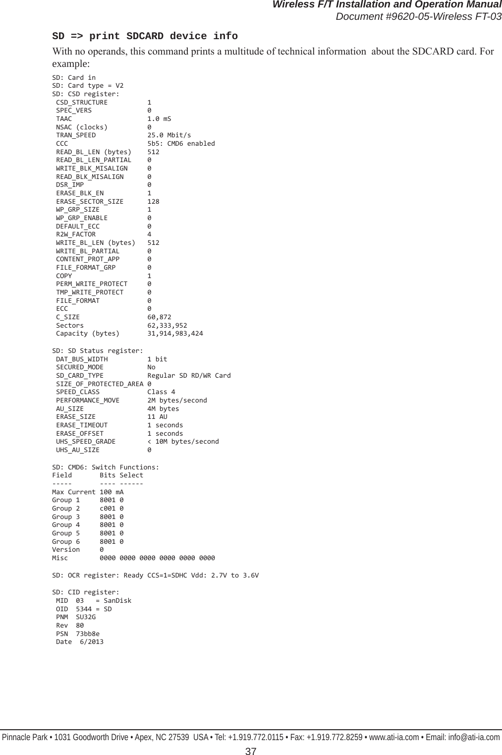
![Wireless F/T Installation and Operation ManualDocument #9620-05-Wireless FT-03Pinnacle Park • 1031 Goodworth Drive • Apex, NC 27539 USA • Tel: +1.919.772.0115 • Fax: +1.919.772.8259 • www.ati-ia.com • Email: info@ati-ia.com 38SD [sector-1] [sector-n] => dump MicroSD sectorsIf sector numbers are given (in hex) this command will dump the contents of the specied sectors on the MicroSD This command is provided for MicroSD rmware testing only. For example, to dump the contents of sector 0x300 (which appears to be part of a directory):>sd 300 SD: Card in SD: Card type = V2 SD: CSD: Capacity (bytes) 1,015,808,000 Sectors 1,984,000 000000 2e20 2020 2020 2020 2020 2010 000b 238b . ...#. 000010 0a37 0a37 0000 238b 0a37 0200 0000 0000 .7.7..#..7...... 000020 2e2e 2020 2020 2020 2020 2010 000b 238b .. ...#. 000030 0a37 0a37 0000 238b 0a37 0000 0000 0000 .7.7..#..7...... 000040 4172 0069 006e 0067 0074 000f 0015 6f00 Ar.i.n.g.t....o. 000050 6e00 6500 7300 0000 ffff 0000 ffff ffff n.e.s........... 000060 5249 4e47 544f 7e31 2020 2010 000c 238b RINGTO~1 ...#. 000070 0a37 0a37 0000 238b 0a37 0300 0000 0000 .7.7..#..7...... 000080 4170 0069 0063 0074 0075 000f 00c8 7200 Ap.i.c.t.u....r. 000090 6500 7300 0000 ffff ffff 0000 ffff ffff e.s............. 0000a0 5049 4354 5552 7e31 2020 2010 000e 238b PICTUR~1 ...#. 0000b0 0a37 0a37 0000 238b 0a37 0400 0000 0000 .7.7..#..7...... 0000c0 416d 0075 0073 0069 0063 000f 009f 0000 Am.u.s.i.c...... 0000d0 ffff ffff ffff ffff ffff 0000 ffff ffff ................ 0000e0 4d55 5349 4330 7e31 2020 2010 000f 238b MUSIC0~1 ...#. 0000f0 0a37 0a37 0000 238b 0a37 0500 0000 0000 .7.7..#..7...... 000100 4176 0069 0064 0065 006f 000f 000e 7300 Av.i.d.e.o....s. 000110 0000 ffff ffff ffff ffff 0000 ffff ffff ................ 000120 5649 4445 4f53 7e31 2020 2010 0000 248b VIDEOS~1 ...$. 000130 0a37 0a37 0000 248b 0a37 0600 0000 0000 .7.7..$..7...... 000140 4173 0079 0073 0074 0065 000f 0072 6d00 As.y.s.t.e...rm. 000150 0000 ffff ffff ffff ffff 0000 ffff ffff ................ 000160 5359 5354 454d 7e31 2020 2012 0002 248b SYSTEM~1 ...$. 000170 0a37 0a37 0000 248b 0a37 0700 0000 0000 .7.7..$..7...... 000180 0000 0000 0000 0000 0000 0000 0000 0000 ................ 000190 => 0001ff same as aboveSD [FORMAT] => Format MicroSDThis command allows you to format the MicroSD™ card. All existing data on the MicroSD™ card will be lost. The command will ask you to verify that you want to format the disk before it actually deletes any data. Any data streaming over the WLAN will be interrupted while the format is taking place.SD [ON | OFF] => Control MicroSD powerThis command allows you to control power to the MicroSD™ card. Issuing other MicroSD™ card commands will also turn the MicroSD power back on. This command is provided for MicroSD rmware testing only.SDW [start] [data] => write MicroSD sectorThis command writes the given data to the specied MicroSD sector. This command is provided for MicroSD rmware testing only.SCD [directory] => Similar to the standard CD commandThis command allows you to display and change the path on the MicroSD.](https://usermanual.wiki/ATI-Automation/9105WNET/User-Guide-2393866-Page-38.png)
![Wireless F/T Installation and Operation ManualDocument #9620-05-Wireless FT-03Pinnacle Park • 1031 Goodworth Drive • Apex, NC 27539 USA • Tel: +1.919.772.0115 • Fax: +1.919.772.8259 • www.ati-ia.com • Email: info@ati-ia.com 39SDEL => [lename] => delete le(s), wild cards * and ? may be usedThis command deletes the selected les in the current directory on the MicroSD. For example:>sdel f2.dat F2.DAT deleted Files deleted: 1SDIR => Print DirectoryThis command prints a directory of all les in the current path on the MicroSD. For example:Directory of 0:/ATI 2010/01/01 00:06 <DIR> . 2010/01/01 00:06 <DIR> .. 2010/01/01 00:56 4 ATI.ini 2010/01/01 00:49 66,446,898 F2.dat 2010/01/01 01:21 20,995,230 F3.dat 2010/01/01 00:07 56,057,184 F4.dat 2010/01/01 00:08 6,677,154 F5.dat 2010/01/01 00:09 4,886,082 F6.dat 2010/01/01 00:09 3,938,868 F7.dat 2010/01/01 00:05 756 F8.dat 2010/01/01 00:05 68,586 F9.dat 2010/01/01 00:05 79,338 F10.dat 2010/01/01 00:05 61,530 F11.dat 2010/01/01 00:05 66,570 F12.dat 2010/01/01 00:02 1,188,993,882 F13.dat 2010/01/01 00:23 11,860,926 F14.dat 2010/01/01 00:14 66,858,426 F15.dat 2010/01/01 16:02 4,294,967,220 F16.dat 16 File(s) 5,721,958,654 bytes 2 Dir(s)](https://usermanual.wiki/ATI-Automation/9105WNET/User-Guide-2393866-Page-39.png)
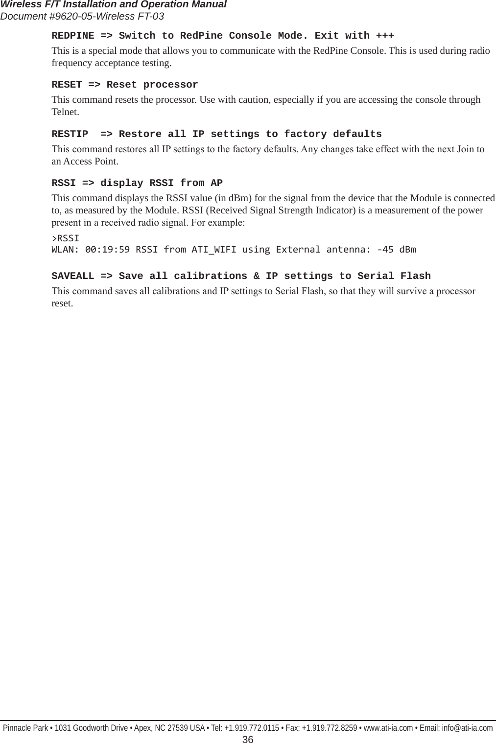
![Wireless F/T Installation and Operation ManualDocument #9620-05-Wireless FT-03Pinnacle Park • 1031 Goodworth Drive • Apex, NC 27539 USA • Tel: +1.919.772.0115 • Fax: +1.919.772.8259 • www.ati-ia.com • Email: info@ati-ia.com 40SDREC [ON | OFF] => Stream packets to MicroSD: on, off, or toggleThis command streams data (in the standard packet format, which is also used for UDP packets) to the MicroSD™ card. All data is placed in the \ATI subdirectory, which is created if it is not already present. The le ati.ini is also created within this subdirectory if it is not already present. Each time that the SDREC ON command is issued, a new le Fn.dat le is created. Note that n is the next sequential le number.Note that the le system only supports le sizes up to 4 G bytes.The data can be read by placing the MicroSD™ card into a computer that supports the FAT le system. A Micro SD to USB adapter may be required. When viewed with the HxD utility, data for a single transducer may look like:Figure5.1—Fn.datleformat Note that if an interruption occurs while this data is being written (such as the removal of the MicroSD™ card or the battery) the open le will generally lose any data written within the last two seconds. The interruption may also cause lost le system clusters, which will reduce the storage capacity of the card. As the WNET unit does not contain a le system repair utility, lost clusters may be repaired either by formatting the card (using the SD FORMAT command, which will cause the loss of all data on the card), or by putting the card into a computer and running the Scandisk utility. On Windows 7 machines this can be done by opening Windows Explorer, right-clicking on the drive letter of the MicroSD™ card and selecting Properties, clicking the Tools tab, pressing the Check Now… button, and the pressing Start.SDUMP[lename] => File dumpThis command prints a hex dump of the specied le on the MicroSD.SF => print Serial Flash device infoThis command prints information about the Serial Flash device. This command is provided for serial ash rmware testing. For example:SF: Maker = Silicon Storage Technology SF: Device = SST25VF010A => 128K bytes SF: Status = 00 BlockProtect = NoneSFR [address] [length] => print Serial Flash memory of length givenThis command prints Serial Flash memory starting at the given address for the given length. This command is provided for serial ash rmware testing. For example, here we dump the rst calibration area for a unit that has no calibrations saved:>sfr 1000 2000 SF: 001000 ffff ffff ffff ffff ffff ffff ffff ffff ................ SF: 001010 => 002fff same as aboveSFW [address] [byte] => write byte to Serial Flash address givenThis command allows you to write a single byte to the Serial Flash. This command is provided for serial ash rmware testing.](https://usermanual.wiki/ATI-Automation/9105WNET/User-Guide-2393866-Page-40.png)
![Wireless F/T Installation and Operation ManualDocument #9620-05-Wireless FT-03Pinnacle Park • 1031 Goodworth Drive • Apex, NC 27539 USA • Tel: +1.919.772.0115 • Fax: +1.919.772.8259 • www.ati-ia.com • Email: info@ati-ia.com 41SS [A] [012345678 any combination or order] => read specied ADC channels onceThis command reads the specied ADC channels once.SS => repeats last SS commandThis command repeats the last SS command, without the need to retype the whole thing.SSI [ADC | DAC | EEPOT | PORTS | SDCARD | SF | WLAN] [bit rate: bits/second] => Set selected SSI bit rateThis command allows you to view information about and set the bit rate for all devices that communicate over an SSI port (SSI is the Stellaris name for SPI). Any new rate takes effect immediately. For example:Device Rate(Hz) Pol Pha Format ------ -------- --- --- ------ ADC 10000000 0 0 Freescale CPLD 10000000 0 0 Freescale DAC 1000000 0 0 Freescale EEPOT 1000000 0 0 Freescale EEPROM 10000000 0 0 Freescale PORTS 10000000 0 0 Freescale SDCARD 10000000 0 0 Freescale SF 10000000 0 0 Freescale WLAN 10000000 0 0 FreescaleWith an 80 MHz clock, the highest bit rates that are supported by the processor hardware are:1. 40,000,000 Hz (no SPI peripherals work at this speed) 2. 20,000,000 Hz 3. 13,333,333 Hz 4. 10,000,000 Hz 5. 8,000,000 HzSSID [case-sensitive string] => Set SSIDThis command allows you to view and set the SSID. The new SSID will be effective after the next Join to an Access Point. An SSID is the name of a wireless local area network. SSIDs are case sensitive text strings. The SSID is a sequence of alphanumeric characters (letters or numbers). SSIDs have a maximum length of 32 characters.STACK => Print stack available messageThis command allows you to view how much of the processor stack is free. Whenever a new low in stack bytes free occurs that is less than 1024 bytes this message will also appear without the command being typed. For example:>stack STACK: 1184 of 4096 bytes freeSTATS => Print packet statistics, [0] to clearThis command prints how many total packets, dropped packets, the maximum length of event that have occurred since power up or the last STATS 0 command in MicroSD writing (due to write latency) and UDP packet transmitting (due to ow control), and the average length of event. For UDP packets this command also prints the average ow control event duration, how many ow control events occurred, and how many times the WLAN Module locked-up and had to be reset. For example:>stats00:03:54 CARD Packets: Generated= 200,678 Dropped= 0 Write Latency: Max= 92 mS Mean= 1.406 mS00:03:54 WLAN Packets: Generated= 200,678 Dropped= 0 Flow Control: Max= 92 mS Mean= 11.178 mS Events= 2,278 Module: Lock-Ups= 0](https://usermanual.wiki/ATI-Automation/9105WNET/User-Guide-2393866-Page-41.png)
![Wireless F/T Installation and Operation ManualDocument #9620-05-Wireless FT-03Pinnacle Park • 1031 Goodworth Drive • Apex, NC 27539 USA • Tel: +1.919.772.0115 • Fax: +1.919.772.8259 • www.ati-ia.com • Email: info@ati-ia.com 42T [ON | OFF] => Transmit packet on, off, or toggleThis command turns the transmission of outgoing UDP data packets to the WLAN Module on and off.TEST [* | Transducer 1 -> 6] [OFF | ZERO | DAC] => Set Self-Test mode on selected Transducer(s)This command sets the self test mode for the selected Transducers:TESTSetting ADCInputforthisTransducerconnectedto:OFF Normal sensor inputZERO Zero signal (2.5V = 0x8000)DAC DAC Channel 6 for this TransducerSet DAC channel 6 output procedure for one Transducer:a. Set active Transducer: TRANS [1 6]b. Set DAC Channel 6 output: O 6 [value: 0 65535 or 0xFFFF]This command generates a report of the self-test status of the unit:>TEST 5 ZERO Tr Self-test-mode -- -------------- 1 OFF 2 OFF 3 OFF 4 OFF 5 ZERO 6 OFFTXPWR [0 | 1 | 2] => Set transmit power after next JoinThis command allows you to set the WLAN Module’s transmit power. The power level change takes place after the next Join to an Access Point.Band 0 = low 1 = medium 2=highGHz dBm +/- 1 mW dBm +/- 1 mW dBm +/- 2 mW2.4 7 5 10 10 15 325 5 3 7 5 12 16](https://usermanual.wiki/ATI-Automation/9105WNET/User-Guide-2393866-Page-42.png)
![Wireless F/T Installation and Operation ManualDocument #9620-05-Wireless FT-03Pinnacle Park • 1031 Goodworth Drive • Apex, NC 27539 USA • Tel: +1.919.772.0115 • Fax: +1.919.772.8259 • www.ati-ia.com • Email: info@ati-ia.com 43USBILIM [value in mA] => set USB current limitThis command sets the USB Input Current Limit (USBILIM) value in Battery Charger Register 0. You must enter an exact value from the following table:ValuemA Meaning Notes 100 Max (USB Low Power) Default setting CLPROG1 and CLPROG2 shorted. Refer to the Input Current Regulation section for information when this register is modied by the LTC4155.500 Max (USB High Power) 600 Max 700 Max 800 Max 900 Max (USB 3.0) 1000 Typical 1250 Typical 1500 Typical 1750 Typical 2000 Typical 2250 Typical 2500 Typical 2750 Typical 3000 Typical 22.5 mA Max (USB Suspend) 0 Select CLPROG1 Default setting two CLPROG resistors. Refer to the Input Current Regulation section for information when this register is modied by the LTC4155.USER => Switch to User ModeThis command switches the Console to User Mode. WLAN [ON | OFF] => Turns WLAN Module power (WIFI_PWREN) on or offThis command controls the WIFI_PWREN bit to the WLAN Module on the Digital Board. The WLAN OFF command also turns off transmission of the regular UDP data packet.WFLOAD => Load WLAN Module, 2-le methodThis command allows you to load the WLAN Module with new rmware using the shorter 2-le method. This is the method that is normally used. This command takes about 5 minutes to execute. Before committing to the WLAN Module update, this command checks to make sure that the necessary les (WiSe_Con and WiSe_WLA) are present in the Serial Flash, have a termination record (so they are probably complete), and have no checksum errors.WFLOAD4 => Load WLAN Module, 4-le methodThis command allows you to load the WLAN Module with new rmware using the longer 4-le method. This longer method is necessary for WLAN Modules that have had the RF Test rmware loaded into them. This command takes about 8 minutes to execute. Before committing to the WLAN Module update, this command checks to make sure that the necessary les (WFU_Cont, WLAN_CON, WiSe_WLA, and WiSe_Con) are present in the Serial Flash, have a termination record (so they are probably complete), and have no checksum errors.](https://usermanual.wiki/ATI-Automation/9105WNET/User-Guide-2393866-Page-43.png)
![Wireless F/T Installation and Operation ManualDocument #9620-05-Wireless FT-03Pinnacle Park • 1031 Goodworth Drive • Apex, NC 27539 USA • Tel: +1.919.772.0115 • Fax: +1.919.772.8259 • www.ati-ia.com • Email: info@ati-ia.com 44WFLOADRF => Load WLAN Module, for RF testingThis command allows you to load the WLAN Module with new rmware for RF testing. This command takes about 2 minutes to execute. Before committing to the WLAN Module update, this command checks to make sure that the necessary les (WiSe_Con.t and WiSe_WLA.t) are present in the Serial Flash, have a termination record (so they are probably complete), and have no checksum errors. These two les must be loaded into the WNET unit, and then renamed by added the .t sufx to each le name before using this command.XPWR [* | Transducer: 1 -> 6] [ON | OFF| BRIDGE | AFE] => Transducer power controlThis command allows you to control the Analog Board power settings for each of the Transducers. The choice for each Transducer is:1. ON. The Analog Front End (AFE) for this Transducer (on the Analog Board) and the external Transducer (BRIDGE) are fully powered.2. OFF. The AFE and the external Transducer are off.3. BRIDGE power only. The AFE is off and the external Transducer is on.4. AFE power only. The AFE is on and the external Transducer is off.The WNET reduces power surges by turning power on gradually. When you issue this command for a Transducer:1. If Transducer ON or BRIDGE-only was selected, and the Analog Power (ANALOG_SHDN bit PF0) was off, Analog Power is turned on, and there is a 0.5 second delay.2. If Transducer OFF was selected, and all Transducers are now off, Analog Power is turned off.3. If Transducer ON was selected, power to the Transducer’s BRIDGE and AFE is turned on. 4. If Transducer OFF was selected, power to the Transducer’s BRIDGE and AFE is turned off.5. If Transducer BRIDGE was selected, power to the Transducer’s BRIDGE is turned on and AFE is turned off.6. If the Transducer’s BRIDGE or AFE state changed to on, there is now a 0.5 second delay.7. If the Transducer’s AFE state changed to on, the Transducer’s DAC and EEPOTs are now written with their calibration values.8. If the Transducer’s BRIDGE or AFE state changed to on, a Current Limit Reset is now performed.This command will also generate a report of the current Transducer power status. The Auto column is what the software is commanding, based on the XPWR command. The Now column is what is actually going out to the power port. If the columns are different, it is because direct test outputs to the Analog Board ports are in use (see the LED1, LED2, and PWR commands). Tr Auto Now -- ---- --- 1 ON ON 2 ON ON 3 ON ON 4 ON ON 5 ON ON 6 ON ON Analog power ON](https://usermanual.wiki/ATI-Automation/9105WNET/User-Guide-2393866-Page-44.png)


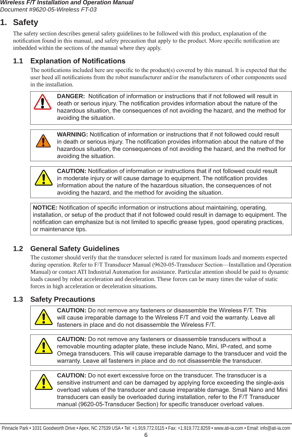
![Wireless F/T Installation and Operation ManualDocument #9620-05-Wireless FT-03Pinnacle Park • 1031 Goodworth Drive • Apex, NC 27539 USA • Tel: +1.919.772.0115 • Fax: +1.919.772.8259 • www.ati-ia.com • Email: info@ati-ia.com 53Appendix A – UDP Command CRC CalculationAll UDP commands sent to the Wireless F/T must include a two-byte CRC (Cyclic Redundancy Check) value. This value is used for error checking the command request and is based on the data in the command structure to be sent.The following C code performs the calculation of the CRC value. To calculate the value, pass a pointer to the command structure along with the command length in bytes minus two to the function crcBuf().// If FAST is dened, then the CRC is determined using a lookup table instead of calculations #dene FAST 1 // Both versions use the CRC-16-CCITT polynomial: x^16 + x^12 + x^5 + 1 = 0x11021#if FAST unsigned short crcByte(unsigned short crc, unsigned char ch) // lookup table version (bigger & faster) { static const unsigned short ccitt_crc16_table[256] = { 0x0000, 0x1021, 0x2042, 0x3063, 0x4084, 0x50a5, 0x60c6, 0x70e7, 0x8108, 0x9129, 0xa14a, 0xb16b, 0xc18c, 0xd1ad, 0xe1ce, 0xf1ef, 0x1231, 0x0210, 0x3273, 0x2252, 0x52b5, 0x4294, 0x72f7, 0x62d6, 0x9339, 0x8318, 0xb37b, 0xa35a, 0xd3bd, 0xc39c, 0xf3ff, 0xe3de, 0x2462, 0x3443, 0x0420, 0x1401, 0x64e6, 0x74c7, 0x44a4, 0x5485, 0xa56a, 0xb54b, 0x8528, 0x9509, 0xe5ee, 0xf5cf, 0xc5ac, 0xd58d, 0x3653, 0x2672, 0x1611, 0x0630, 0x76d7, 0x66f6, 0x5695, 0x46b4, 0xb75b, 0xa77a, 0x9719, 0x8738, 0xf7df, 0xe7fe, 0xd79d, 0xc7bc, 0x48c4, 0x58e5, 0x6886, 0x78a7, 0x0840, 0x1861, 0x2802, 0x3823, 0xc9cc, 0xd9ed, 0xe98e, 0xf9af, 0x8948, 0x9969, 0xa90a, 0xb92b, 0x5af5, 0x4ad4, 0x7ab7, 0x6a96, 0x1a71, 0x0a50, 0x3a33, 0x2a12, 0xdbfd, 0xcbdc, 0xfbbf, 0xeb9e, 0x9b79, 0x8b58, 0xbb3b, 0xab1a, 0x6ca6, 0x7c87, 0x4ce4, 0x5cc5, 0x2c22, 0x3c03, 0x0c60, 0x1c41, 0xedae, 0xfd8f, 0xcdec, 0xddcd, 0xad2a, 0xbd0b, 0x8d68, 0x9d49, 0x7e97, 0x6eb6, 0x5ed5, 0x4ef4, 0x3e13, 0x2e32, 0x1e51, 0x0e70, 0xff9f, 0xefbe, 0xdfdd, 0xcffc, 0xbf1b, 0xaf3a, 0x9f59, 0x8f78, 0x9188, 0x81a9, 0xb1ca, 0xa1eb, 0xd10c, 0xc12d, 0xf14e, 0xe16f, 0x1080, 0x00a1, 0x30c2, 0x20e3, 0x5004, 0x4025, 0x7046, 0x6067, 0x83b9, 0x9398, 0xa3fb, 0xb3da, 0xc33d, 0xd31c, 0xe37f, 0xf35e, 0x02b1, 0x1290, 0x22f3, 0x32d2, 0x4235, 0x5214, 0x6277, 0x7256, 0xb5ea, 0xa5cb, 0x95a8, 0x8589, 0xf56e, 0xe54f, 0xd52c, 0xc50d, 0x34e2, 0x24c3, 0x14a0, 0x0481, 0x7466, 0x6447, 0x5424, 0x4405, 0xa7db, 0xb7fa, 0x8799, 0x97b8, 0xe75f, 0xf77e, 0xc71d, 0xd73c, 0x26d3, 0x36f2, 0x0691, 0x16b0, 0x6657, 0x7676, 0x4615, 0x5634, 0xd94c, 0xc96d, 0xf90e, 0xe92f, 0x99c8, 0x89e9, 0xb98a, 0xa9ab, 0x5844, 0x4865, 0x7806, 0x6827, 0x18c0, 0x08e1, 0x3882, 0x28a3, 0xcb7d, 0xdb5c, 0xeb3f, 0xfb1e, 0x8bf9, 0x9bd8, 0xabbb, 0xbb9a, 0x4a75, 0x5a54, 0x6a37, 0x7a16, 0x0af1, 0x1ad0, 0x2ab3, 0x3a92, 0xfd2e, 0xed0f, 0xdd6c, 0xcd4d, 0xbdaa, 0xad8b, 0x9de8, 0x8dc9, 0x7c26, 0x6c07, 0x5c64, 0x4c45, 0x3ca2, 0x2c83, 0x1ce0, 0x0cc1, 0xef1f, 0xff3e, 0xcf5d, 0xdf7c, 0xaf9b, 0xbfba, 0x8fd9, 0x9ff8, 0x6e17, 0x7e36, 0x4e55, 0x5e74, 0x2e93, 0x3eb2, 0x0ed1, 0x1ef0 }; return ccitt_crc16_table[((crc >> 8) ^ ch) & 0xff] ^ (crc << 8); }](https://usermanual.wiki/ATI-Automation/9105WNET/User-Guide-2393866-Page-53.png)
![Wireless F/T Installation and Operation ManualDocument #9620-05-Wireless FT-03Pinnacle Park • 1031 Goodworth Drive • Apex, NC 27539 USA • Tel: +1.919.772.0115 • Fax: +1.919.772.8259 • www.ati-ia.com • Email: info@ati-ia.com 54#else unsigned short crcByte(unsigned short crc, unsigned char ch) // direct calculation version (smaller & slower) { unsigned short crc_new = (unsigned char)(crc >> 8) | (crc << 8); crc_new ^= ch; crc_new ^= (unsigned char)(crc_new & 0xff) >> 4; crc_new ^= crc_new << 12; crc_new ^= (crc_new & 0xff) << 5; return crc_new; } #endif#dene CRC_INIT 0x1234 // this is the seed value used for along with the buffer’s rst byte unsigned short crcBuf(const void * buff, unsigned long len) { unsigned long i; unsigned short crc = CRC_INIT; const char * buf = buff; for(i = 0; i < len; i++) { crc = crcByte(crc, buf[i]); } return crc; }](https://usermanual.wiki/ATI-Automation/9105WNET/User-Guide-2393866-Page-54.png)