ATI Automation 9105WNET Wireless Multi-Axis Force/Torque Transmitter User Manual 9620 05
ATI Industrial Automation Wireless Multi-Axis Force/Torque Transmitter 9620 05
User Manual - 9620-05

Engineered Products for Robotic Productivity
Pinnacle Park • 1031 Goodworth Drive • Apex, NC 27539 USA • Tel: +1.919.772.0115 • Fax: +1.919.772.8259 • www.ati-ia.com • Email: info@ati-ia.com
Wireless Force/Torque Sensor System
Installation and Operation Manual
Document #: 9620-05-Wireless FT-03
May 2014

Wireless F/T Installation and Operation Manual
Document #9620-05-Wireless FT-03
Pinnacle Park • 1031 Goodworth Drive • Apex, NC 27539 USA • Tel: +1.919.772.0115 • Fax: +1.919.772.8259 • www.ati-ia.com • Email: info@ati-ia.com
2
Foreword
Information contained in this document is the property of ATI Industrial Automation, Inc. and shall not be reproduced in
whole or in part without prior written approval of ATI Industrial Automation, Inc. The information herein is subject to
change without notice and should not be construed as a commitment of ATI Industrial Automation, Inc. This manual is
periodically revised to reect and incorporate changes made to the F/T system.
ATI Industrial Automation, Inc. assumes no responsibility for any errors or omissions in this document.
Copyright © by ATI Industrial Automation, Inc., Apex, North Carolina USA. All Rights Reserved. Published in the USA.
In consideration that ATI Industrial Automation, Inc. (ATI) products are intended for use with robotic and/or automated
machines, ATI does not recommend the use of its products for applications wherein failure or malfunction of an ATI
component or system threatens life or makes injury probable. Anyone who uses or incorporates ATI components within
any potentially life-threatening system must obtain ATI’s prior consent based upon assurance to ATI that a malfunction
of ATI’s component does not pose direct or indirect threat of injury or death, and (even if such consent is given) shall
indemnify ATI from any claim, loss, liability, and related expenses arising from any injury or death resulting from use of
ATI components.
All trademarks belong to their respective owners.
Windows™ is a registered trademark of Microsoft Corporation.
MicroSD is a trademark of SD-3C, LLC
Wi-Fi Direct is a trademark of the Wi-Fi Alliance
Note
Please read the manual before calling customer service. Before calling, have the following
information available:
1. Serial number (e.g., FT01234)
2. Transducer model (e.g., Nano17, Gamma, Theta, etc.)
3. Calibration (e.g., US-15-50, SI-65-6, etc.)
4. Accurate and complete description of the question or problem
5. Computer and software information. Operating system, PC type, drivers, application
software, and other relevant information about your conguration.
If possible, be near the F/T system when calling.
How to Reach Us
Sale, Service and Information about ATI products:
ATI Industrial Automation
1031 Goodworth Drive
Apex, NC 27539 USA
www.ati-ia.com
Tel: 919.772.0115
Fax: 919.772.8259
E-mail: info@ati-ia.com
Technical support and questions:
Application Engineering
Tel: 919.772.0115, Option 2, Option 2
Fax: 919.772.8259
E-mail: ft_support@ati-ia.com

Wireless F/T Installation and Operation Manual
Document #9620-05-Wireless FT-03
Pinnacle Park • 1031 Goodworth Drive • Apex, NC 27539 USA • Tel: +1.919.772.0115 • Fax: +1.919.772.8259 • www.ati-ia.com • Email: info@ati-ia.com
3
Table of Contents
1. Safety ......................................................................................................................................... 6
1.1 ExplanationofNotications .........................................................................................................6
1.2 General Safety Guidelines ............................................................................................................6
1.3 Safety Precautions ........................................................................................................................6
2. System Overview ...................................................................................................................... 8
2.1 Wireless F/T WNet-3 ......................................................................................................................9
2.2 Wireless F/T WNet-6 ....................................................................................................................10
2.3 Antenna ........................................................................................................................................ 10
2.4 Micro USB Conector ................................................................................................................... 11
2.5 MicoSD™ Card Slot ..................................................................................................................... 11
2.6 External Power Adapter .............................................................................................................. 11
2.7 USB Cable .................................................................................................................................... 11
2.8 Removable Belt Clip .................................................................................................................... 11
2.9 Removable Battery ...................................................................................................................... 11
2.10 Controls and Indicators .............................................................................................................. 11
2.10.1 Power Button .................................................................................................................... 11
2.10.2 Power Button Indicator ..................................................................................................... 11
2.10.3 Transducer Status Indicators ............................................................................................ 12
2.10.4 Wireless Status Indicator .................................................................................................. 12
2.10.5 Battery Status Indicator .................................................................................................... 12
2.10.6 External Power Indicator .................................................................................................. 12
3. Installation .............................................................................................................................. 13
3.1 Typical Belt Clip Installation .......................................................................................................14
3.2 Typical Fixed Installation ............................................................................................................14
3.3 External Power Adapter Installation .......................................................................................... 14
3.4 InitialConguration ....................................................................................................................14
3.5 InstallingtheWirelessF/TJavaDemoApplicationonaPC ................................................... 16
3.6 StartingtheWirelessF/TJavaDemoApplication ....................................................................17
3.7 EstablishingaConnectiontotheWirelessF/TandMonitoringData ....................................18
3.8 Data Collection ............................................................................................................................19
3.8.1 Collecting and Storing Data on a MicroSD™ Card .......................................................... 19
3.8.2 Collecting and Storing Data on a PC or Network File ...................................................... 19
4. InstallingtheTransducer ....................................................................................................... 20

Wireless F/T Installation and Operation Manual
Document #9620-05-Wireless FT-03
Pinnacle Park • 1031 Goodworth Drive • Apex, NC 27539 USA • Tel: +1.919.772.0115 • Fax: +1.919.772.8259 • www.ati-ia.com • Email: info@ati-ia.com
4
5. Command Interface ................................................................................................................ 21
5.1 Communication Interfaces .........................................................................................................21
5.2 UPD Interface ...............................................................................................................................21
5.3 UDP Command Format .............................................................................................................. 21
5.4 Commands ...................................................................................................................................22
6. Maintenance ............................................................................................................................ 45
6.1 Preventive Maintenance .............................................................................................................45
6.2 BatteryRechargingandReplacement ......................................................................................45
6.2.1 Charging Battery Internally ............................................................................................... 45
6.2.2 Charging Battery Externally .............................................................................................. 45
7. Troubleshooting ..................................................................................................................... 46
8. Serviceable Parts ................................................................................................................... 46
9. Specications ......................................................................................................................... 47
9.1 WirelessCharacteristics .............................................................................................................47
9.2 Power Requirements ...................................................................................................................47
9.3 PhysicalCharacteristics .............................................................................................................47
10. RegulatoryInformation .......................................................................................................... 48
10.1 FCC Statement .............................................................................................................................48
10.2 Canadian Compliance Statement ..............................................................................................49
11. Drawings ................................................................................................................................. 50
11.1 Wireless Net F/T for 3 Transducers ........................................................................................... 50
11.2 Wireless Net F/T for 6 Transducers ........................................................................................... 51
12. Terms and Conditions of Sale ............................................................................................... 52
Appendix A – UDP Command CRC Calculation ......................................................................... 53
AppendixB–InitialCongurationUsingaTelnetProgam(PuTTY) ........................................ 55
B.1 InitialCongurationUsing ........................................................................................................55

Wireless F/T Installation and Operation Manual
Document #9620-05-Wireless FT-03
Pinnacle Park • 1031 Goodworth Drive • Apex, NC 27539 USA • Tel: +1.919.772.0115 • Fax: +1.919.772.8259 • www.ati-ia.com • Email: info@ati-ia.com
5
Glossary of Terms
Terms Denitions
Big-endian Indicates the most signicant byte of a value is stored rst.
DHCP Dynamic Host Conguration Protocol (DHCP) is an automatic method for
Ethernet equipment to obtain an IP address. The WNet system can obtain its
IP address using DHCP on networks that support this protocol.
Ethernet Network Switch Ethernet network switches are electronic devices that connect multiple
Ethernet cables to an Ethernet network while directing the ow of trafc.
F/T Force/Torque.
Gateway Settings The address of the router that handles a network’s Ethernet trafc.
IEEE The Institute of Electrical and Electronics Engineer, inc.
IP Address An Internet Protocol Address (IP Address) is an electronic address assigned
to an Ethernet device so that it may send and receive Ethernet data. IP
addresses may be either manually selected by the user or automatically
assigned by the DHCP protocol.
IPv4 Internet Protocol version 4 (IPv4) is a standard used for specifying the
electronic address of an Ethernet device. The Wireless F/T supports only IPv4.
MAC Address Media Access Control Addresses (MAC Addresses) are the unique addresses
given to every Ethernet device when it is manufactured, to be used as an
electronic Ethernet serial number.
Network Order The order in which data values are placed on a network. The WNet’s network
order is big-endian
RDT Raw Data Transfer (RDT) is a fast and simple WNet protocol for control and
data transfer via UDP.
Sensor System The assembly consisting of all components from the transducer to the WNet
box.
Subnet Mask A string of numbers used to indicate which portion of a network’s IP addresses
is common to all devices on the local network.
TCP Transmission Control Protocol (TCP) is a method of exchanging information
frequently used over Ethernet.
UDP User Datagram Protocol (UDP) is a low-level method of transmitting data
over Ethernet. While UDP is faster than TCP, unlike TCP lost UDP data is not
resent.
USB Universal Serial Bus (USB). The WNet’s USB port conforms to this computer
peripheral cabling standard.
WLAN Wireless Local Area Network (WLAN). The WNet system conforms to the IEEE
802.11 WLAN standard.
Wireless F/T Installation and Operation Manual
Document #9620-05-Wireless FT-03
Pinnacle Park • 1031 Goodworth Drive • Apex, NC 27539 USA • Tel: +1.919.772.0115 • Fax: +1.919.772.8259 • www.ati-ia.com • Email: info@ati-ia.com
6
1. Safety
The safety section describes general safety guidelines to be followed with this product, explanation of the
notication found in this manual, and safety precaution that apply to the product. More specic notication are
imbedded within the sections of the manual where they apply.
1.1 ExplanationofNotications
The notications included here are specic to the product(s) covered by this manual. It is expected that the
user heed all notications from the robot manufacturer and/or the manufacturers of other components used
in the installation.
DANGER: Notication of information or instructions that if not followed will result in
death or serious injury. The notication provides information about the nature of the
hazardous situation, the consequences of not avoiding the hazard, and the method for
avoiding the situation.
WARNING: Notication of information or instructions that if not followed could result
in death or serious injury. The notication provides information about the nature of the
hazardous situation, the consequences of not avoiding the hazard, and the method for
avoiding the situation.
CAUTION: Notication of information or instructions that if not followed could result
in moderate injury or will cause damage to equipment. The notication provides
information about the nature of the hazardous situation, the consequences of not
avoiding the hazard, and the method for avoiding the situation.
NOTICE: Notication of specic information or instructions about maintaining, operating,
installation, or setup of the product that if not followed could result in damage to equipment. The
notication can emphasize but is not limited to specic grease types, good operating practices,
or maintenance tips.
1.2 General Safety Guidelines
The customer should verify that the transducer selected is rated for maximum loads and moments expected
during operation. Refer to F/T Transducer Manual (9620-05-Transducer Section—Installation and Operation
Manual) or contact ATI Industrial Automation for assistance. Particular attention should be paid to dynamic
loads caused by robot acceleration and deceleration. These forces can be many times the value of static
forces in high acceleration or deceleration situations.
1.3 Safety Precautions
CAUTION: Do not remove any fasteners or disassemble the Wireless F/T. This
will cause irreparable damage to the Wireless F/T and void the warranty. Leave all
fasteners in place and do not disassemble the Wireless F/T.
CAUTION: Do not remove any fasteners or disassemble transducers without a
removable mounting adapter plate, these include Nano, Mini, IP-rated, and some
Omega transducers. This will cause irreparable damage to the transducer and void the
warranty. Leave all fasteners in place and do not disassemble the transducer.
CAUTION: Do not exert excessive force on the transducer. The transducer is a
sensitive instrument and can be damaged by applying force exceeding the single-axis
overload values of the transducer and cause irreparable damage. Small Nano and Mini
transducers can easily be overloaded during installation, refer to the F/T Transducer
manual (9620-05-Transducer Section) for specic transducer overload values.

Wireless F/T Installation and Operation Manual
Document #9620-05-Wireless FT-03
Pinnacle Park • 1031 Goodworth Drive • Apex, NC 27539 USA • Tel: +1.919.772.0115 • Fax: +1.919.772.8259 • www.ati-ia.com • Email: info@ati-ia.com
7
CAUTION: When setting up the Wireless F/T system adhere to the minimum bend
radius. Bending the cables tighter than the minimum will cause damage to the cable.
Refer to the F/T Transducer manual (9620-05-Transducer Section) for minimum bend
radii.
CAUTION: Damage to the outer jacketing of the transducer cable could enable
moisture or water to enter an otherwise sealed transducer. Ensure the cable jacketing
is in good condition to prevent transducer damage
Wireless F/T Installation and Operation Manual
Document #9620-05-Wireless FT-03
Pinnacle Park • 1031 Goodworth Drive • Apex, NC 27539 USA • Tel: +1.919.772.0115 • Fax: +1.919.772.8259 • www.ati-ia.com • Email: info@ati-ia.com
8
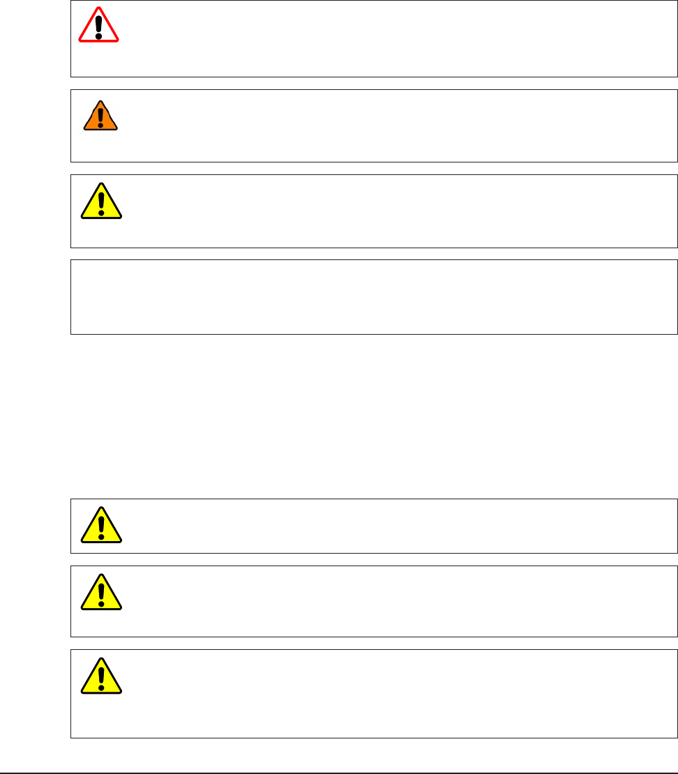
2. System Overview
The Wireless F/T can stream data to an existing wireless access point on the network. The Wireless F/T can stream
six-axis measurements to the user’s host device for data collection, real-time motion control, or user-dened signal
processing.
The range and performance of the Wireless F/T device is derived from the IEEE 802.11 standard. Actual
performance may vary due to conditions, wireless infrastructure, and other variables. Refer to Section 9—
Specications for more details.
Figure2.1—SignalPathtoaComputer,UsingaWirelessAccessPoint
PC Host
Transducer
Wireless F/T
Wireless
Infrastructure
Access
The Wireless F/T is a small signal conditioner and IEEE 802.11 wireless device for up to six ATI Multi-Axis Force/
Torque transducers. The device supports TW transducers (such as Nano and Mini); transducers with integrated
electronics are not supported. The Wireless F/T can stream F/T six-axis measurements to the user’s host device for
data collection, real-time motion control, or user-dened signal processing. The device is equipped with a slot for a
MicroSD™ card, the card can be used to collect and store data. Transducer calibration settings can be downloaded
into the Wireless F/T to allow users to easily replace transducers in the eld for new congurations. The Wireless
F/T is contained in an impact, splash, and dust resistant housing.
The Wireless F/T unit is certied with the antenna attached, the antenna can be pivoted 90° so the unit can be
use in small conned spaces. Fixed mounting is accommodated with the four robust threaded inserts on the back
plate of the housing. The unit can also be attached with a quick-removable belt clip for mobile applications. Both
Wireless F/T models can be powered by an internal rechargeable battery for more mobile applications. The units
can also be powered with a 5VDC external power adapter using the USB connector. The Wireless F/T has a battery
charge status indicator that provides a low-battery warning. The battery can be charged internally or externally. The
external power indicator is active when charging the battery internally or an external power adapter is used.
Wireless F/Ts include a rechargeable battery, antenna, external battery charger and USB cable. Optional desktop
battery charger and international power cords are available, refer to Section 8—Serviceable Parts for more details.
Wireless F/T Installation and Operation Manual
Document #9620-05-Wireless FT-03
Pinnacle Park • 1031 Goodworth Drive • Apex, NC 27539 USA • Tel: +1.919.772.0115 • Fax: +1.919.772.8259 • www.ati-ia.com • Email: info@ati-ia.com
9
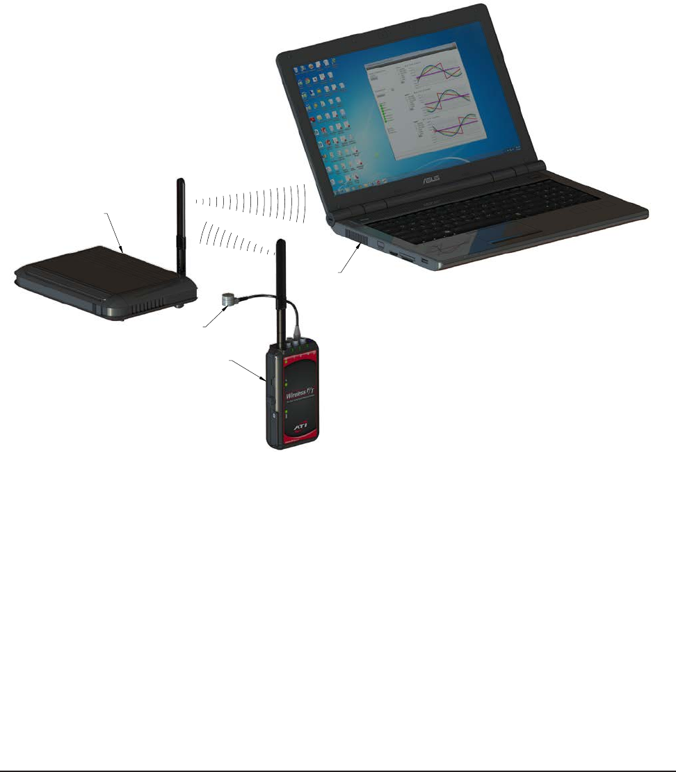
2.1 Wireless F/T WNet-3
The Wireless F/T WNet-3 model can interface with up to three ATI Multi-Axis Force/Torque transducers
simultaneously. Each of the three transducer connectors has a transducer status indicator. The device has a
rechargeable battery that can power the device for approximately two hours at full measurement rate with
all three transducers enabled. The battery life can be extended at lower rates and/or by disabling one or more
transducers.
Figure2.2—Wireless F/T WNet-3
External Power Adapter
Removable
Battery
USB Cable
TW Transducer
Transducer Serial
Number Label
Antenna
Wireless Status Indicator
(3) Transducer
Connectors
Power Button with Indicator
(3) Transducer Status Indicators
External Power Indicator
Battery Status Indicator
MicroSD Card
Transducer Serial
Number Label(s)
Battery Door Lock
(4) Fixed Mounting
Threaded Inserts
Micro USB
Connector
MicroSD Card Slot
Removable Belt Clip
Section 2.10.3
Section 2.10.2
Section 2.10.6
Section 2.10.5
Section 2.10.4
Wireless F/T Installation and Operation Manual
Document #9620-05-Wireless FT-03
Pinnacle Park • 1031 Goodworth Drive • Apex, NC 27539 USA • Tel: +1.919.772.0115 • Fax: +1.919.772.8259 • www.ati-ia.com • Email: info@ati-ia.com
10
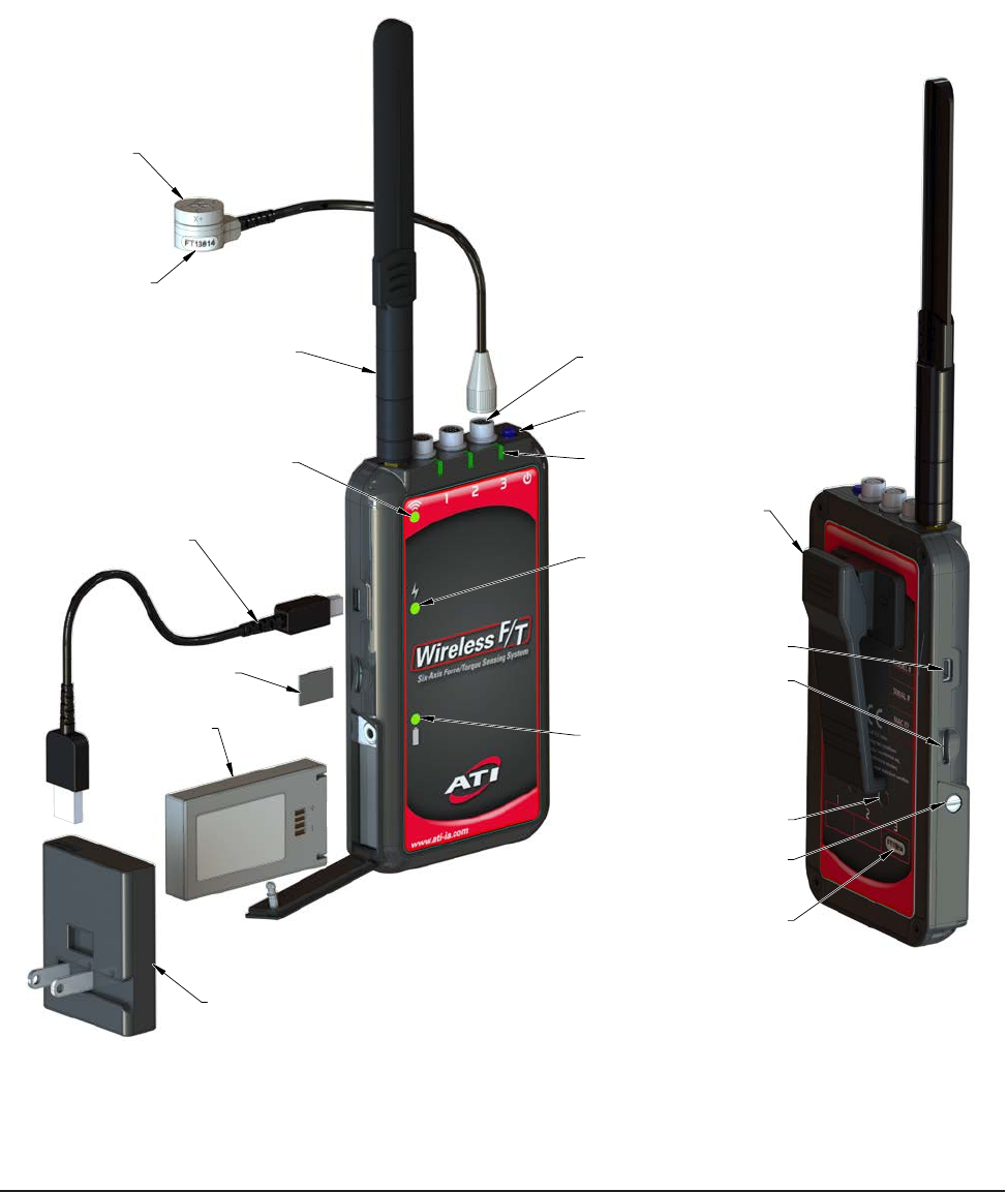
2.2 Wireless F/T WNet-6
The Wireless F/T WNet-6 model can interface with up to six ATI Multi-Axis Force/Torque transducers
simultaneously. Each of the six transducer connectors has a transducer status indicator. The device has a
rechargeable battery that can power the device for approximately one hour at full measurement rate with
all six transducers enabled. The battery life can be extended at lower rates and/or by disabling one or more
transducers.
Figure2.3—Wireless F/T WNet-6
External Power Adapter
Removable
Battery
USB Cable
TW Transducer
Transducer Serial
Number Label
Antenna
Wireless Status Indicator
(6) Transducer
Connectors
Power Button with Indicator
(6) Transducer Status Indicators
External Power Indicator
Battery Status Indicator
MicroSD Card
Transducer Serial
Number Label(s)
Battery Door Lock
(4) Fixed Mounting
Threaded Inserts
Micro USB
Connector
MicroSD Card Slot
Removable Belt Clip
Section 2.10.2
Section 2.10.3
Section 2.10.6
Section 2.10.5
Section 2.10.4
2.3 Antenna
The Wireless F/T Unit has been certied with the antenna. The antenna can pivot 90° to allow the Wireless
F/T unit to t into small conned spaces.

Wireless F/T Installation and Operation Manual
Document #9620-05-Wireless FT-03
Pinnacle Park • 1031 Goodworth Drive • Apex, NC 27539 USA • Tel: +1.919.772.0115 • Fax: +1.919.772.8259 • www.ati-ia.com • Email: info@ati-ia.com
11
2.4 Micro USB Conector
The Wireless F/T unit has a Micro USB connector that can be used to power the unit and charge the battery
using an external power adapter.
2.5 MicoSD™ Card Slot
The WNet unit has a MicroSD card slot that can be used to store data on a customer supplied MircoSD card.
The le system supports les sizes up to 4 G bytes. If using a MicroSD card to store data, the system will
create a subdirectory \ATI and a Fn.dat data le on the MicroSD card. If multiple sessions are saved on the
MicroSD card the system will sequence the data le F1.dat, F2.dat ... etc. Refer to Section 5—Command
Interface for more information.
2.6 External Power Adapter
The external power adapter is a 5V 10W battery charging adapter that provides a power source to operate
the unit and charge the battery. The adapter operates on 100 to 240 AC Input voltage and provides a USB
Micro-A output connector. Interchagable AC clips that t over the US prongs are available for international
use.
2.7 USB Cable
The USB cable connects the external power adapter to the Wireless F/T unit and provides USB Type A and
Micro-B USB connectors.
2.8 Removable Belt Clip
The Wireless F/T unit has a removable belt clip for easily mounting and removal from human or humanoid
robot applications.
2.9 Removable Battery
A rechargeable lithium-polymer battery is provided with the Wireless F/T unit. The battery can be
charged using the external power adapter through the micro USB connector, refer to Section 6.2—Battery
Recharging and Replacement for more information.
2.10 Controls and Indicators
The Wireless F/T has controls and integrated status indicators. The Status indicator information is
periodically transmitted over the wireless network to the host device. See Figure 2.2—Wireless F/T WNet-3
or Figure 2.3— Wireless F/T WNet-6 for location of controls and indicators.
2.10.1 Power Button
The Power Button turns power on and off to the unit. The recessed power on/off switch has an
integrated system status indicator and supports auto power-off. The Power Button supports the
following functionality:
• Press the button once to power the unit up.
• Press button for approximately 2 seconds to power the unit down.
• Press the button for about 10 seconds to power cycle the system.
The power cycling the system will reset the DHCP, IP address, subnet mask, gateway settings, and
authenticated user password to the last saved settings.
2.10.2 Power Button Indicator
This indicator is located within the recessed power switch.
Table 2.1—System Status Indicator
Behavior Description
Off Indicates the system is either off or in charging-only mode.
Steady Blue Indicates the system is on.

Wireless F/T Installation and Operation Manual
Document #9620-05-Wireless FT-03
Pinnacle Park • 1031 Goodworth Drive • Apex, NC 27539 USA • Tel: +1.919.772.0115 • Fax: +1.919.772.8259 • www.ati-ia.com • Email: info@ati-ia.com
12
2.10.3 Transducer Status Indicators
The Wireless F/T WNet-3 has three transducer status indicators on the front of the device, below its
corresponding connector. The Wireless F/T WNet-6 has six transducer indicators, three on the front
of the device and three on the back below its corresponding connector.
Table 2.2—Transducer Status Indicators
Behavior Description
Steady Green Indicates normal transducer operation.
Steady Red Indicates a fault with the transducer.
Off Indicates the transducer is off, the entire unit is off, or the unit is in
charging-only mode.
2.10.4 Wireless Status Indicator
The wireless status indicator is on the front of the Wireless F/T below the antenna connector.
Table 2.3—Wireless Status Indicator
Behavior Description
Steady Green Indicates the unit is connected to an Access Point and there have been
no recent wireless errors.
Flashing Green Indicates the unit is attempting to connect to an Access Point.
Steady Red Indicates the unit is connected to an Access Point, and an error has
been recently detected.
Flashing Red Indicates the wireless subsystem is recovering from a lock-up
condition. Refer to Section 7—Troubleshooting
Off Indicates the unit is either off or in charging-only mode, or the WLAN is
set to off.
2.10.5 Battery Status Indicator
The battery indicator is on the front of the device next to the battery compartment.
Table 2.4—Battery Status Indicator
Behavior Description
Steady Green Indicates the battery is charged.
Flashing Green Indicates the battery is charging.
Flashing Red Indicates the battery charge is almost depleted.
Steady Red Indicates a battery fault, such as the battery voltage is too low, or the
battery is too warm, or is missing.
Off Indicates the unit is off.
2.10.6 External Power Indicator
The external power indicator is on the front of the unit next to the left-side located USB connector.
Table 2.5—External Power Status Indicator
Behavior Description
Steady Green Indicates the external power source connected to the USB port is
operating normally.
Steady Red Indicates the external power source connected to the USB port is not
supplying proper voltage.
Off Indicates there is no external power adapter connected to the USB port,
or it is not functioning.
Wireless F/T Installation and Operation Manual
Document #9620-05-Wireless FT-03
Pinnacle Park • 1031 Goodworth Drive • Apex, NC 27539 USA • Tel: +1.919.772.0115 • Fax: +1.919.772.8259 • www.ati-ia.com • Email: info@ati-ia.com
13
3. Installation
The Wireless F/T system consist of several components: Wireless F/T unit, transducer, external power adapter, USB
cable, and software CD. The Wireless F/T unit must be set up and congured before installing the transducer so that
forces can be monitored during installation.
The Wireless F/T has a removable belt clip that can be used for mobile application. There is also a xed mounting
option that uses four threaded inserts on the rear of the housing. To set up the Wireless F/T system, perform the
following steps:
1. Unpack the system components from the container.
2. Using a at head screw driver, turn the quarter turn screw and open the battery door (Note: 90 degrees
clockwise to open and 90 degrees counterclockwise to close). Insert the battery, close and secure the battery
door. (Note: the battery will only t in one way with the label on the battery facing the front of the Wireless F/T
Unit as shown in Figure 2.2 or Figure 2.3). If the unit is to be powered by an external power adapter refer to
Section 3.3—External Power Adapter Installation.
3. Attach the antenna to the Wireless F/T Unit.
4. Ensure each Transducer and the corresponding Wireless F/T connector are labeled with the same serial number,
refer to Figure 2.2 or Figure 2.3. Connect the transducer cable to the connector on the Wireless F/T unit. (Note:
The cable connector has a notch that ensures the proper orientation to the connector on the Wireless F/T unit.
The connector may have to be rotated until the notch lines up with the connector on the wireless unit. The
connector will drop into place when they are lined up). Tighten the connector nger tight.
5. Connect the USB cable to the Wireless F/T unit and the external power adapter provided. Plug the power
adapter into the wall.
6. Wait for the battery charge Status indicator to transition from ashing to solid green indicating the battery is
fully charged. This will take approximately XXX minutes with a factory-new battery.
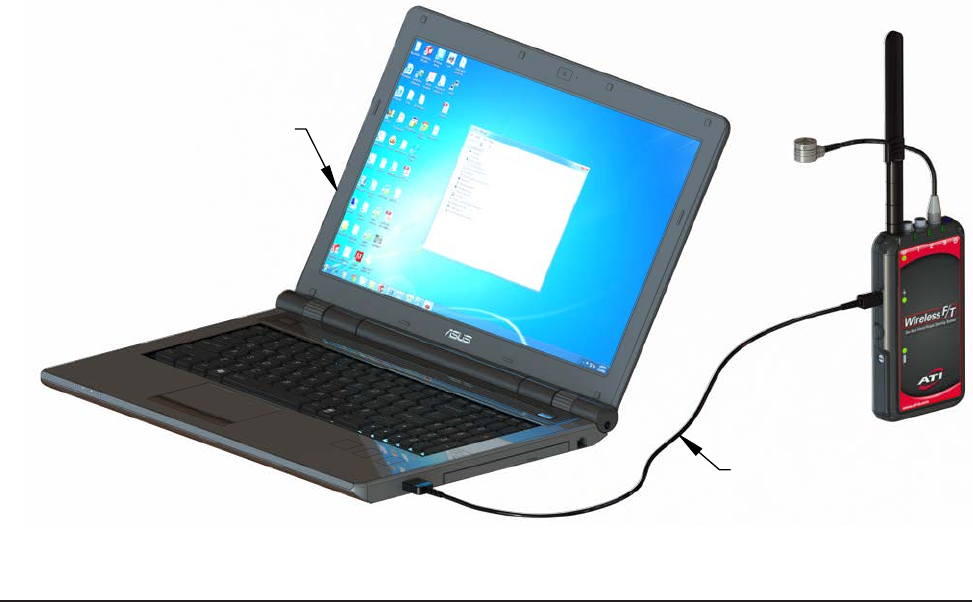
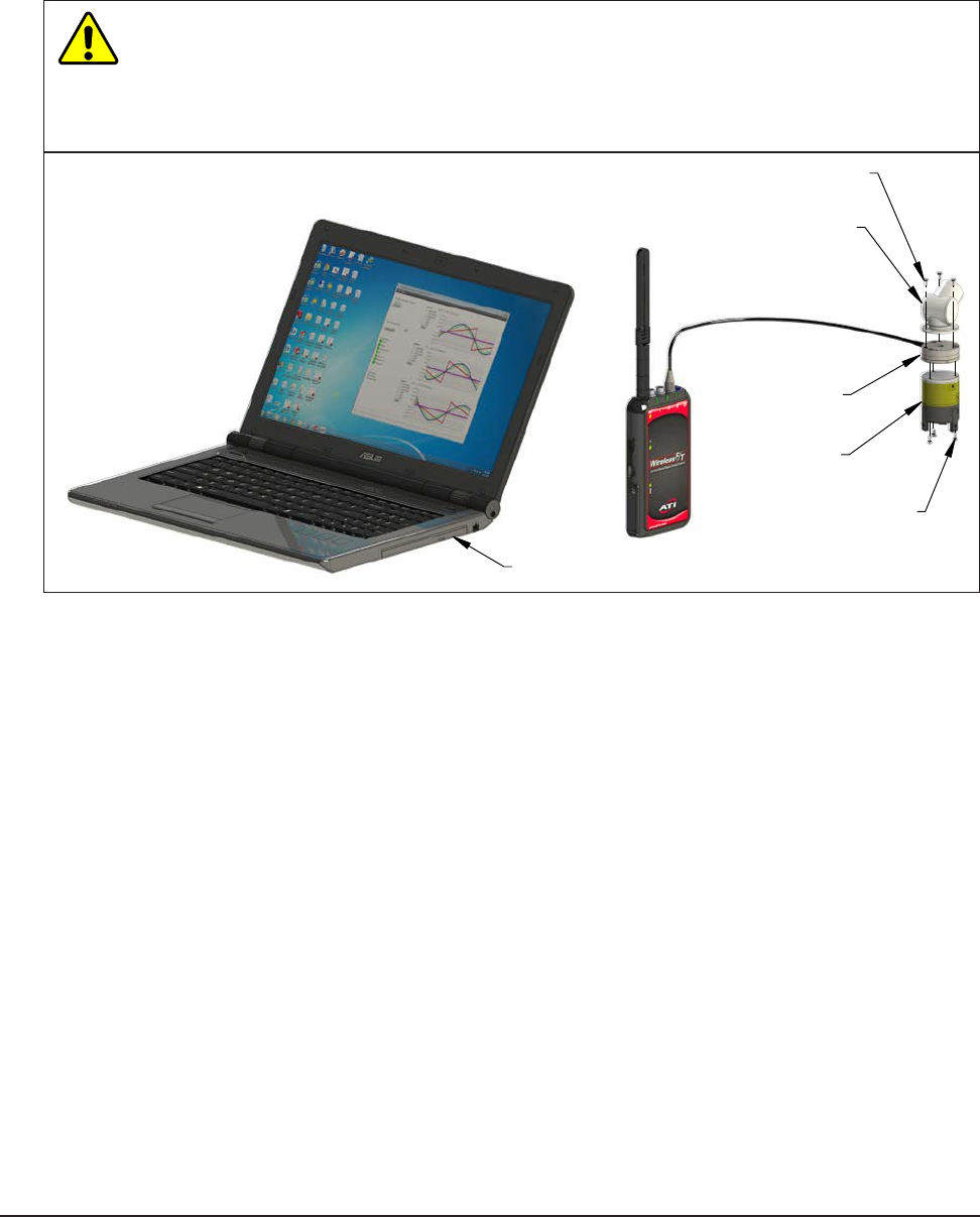
7. Disconnect the USB cable from the power supply and plug into USB port on the computer to be used to
congure the Wireless F/T unit. Refer to Figure 3.1. Note: The computer connected to the USB port does not
provide sufcient source to keep the battery charged.
Figure3.1—ConnecttheUSBcablefromtheWirelessunittotheComputer
Connect the USB cable
to the Computer
Computer Used to Configure
the Wireless F/T Unit

Wireless F/T Installation and Operation Manual
Document #9620-05-Wireless FT-03
Pinnacle Park • 1031 Goodworth Drive • Apex, NC 27539 USA • Tel: +1.919.772.0115 • Fax: +1.919.772.8259 • www.ati-ia.com • Email: info@ati-ia.com
14
8. Momentarity press the power button, the system status indicator will turn on blue once then turn off indicating
system normal.
NOTICE: The system will take a moment to initialize; after initialization the Battery indicator should
illuminate steady green indicating charged. The Transducer status indicator that the Transducer is
connected to should illuminate steady green indicating normal condition. The Transmit Status Indicator
will ash green until the Wireless F/T is congured and connected to a wireless network.
9. Install the Wireless F/T unit, refer to Section 3.1—Typical Belt Clip Installation or Section 3.2—Typical Fixed
Installation.
10. If using an external Power adapter, refer to Section 3.3—External Power Adapter Installation for instructions
11. Congure the Wireless FT unit, refer to Section3.4—InitialConguration.
CAUTION: Damage to the outer jacketing of the transducer cable could enable moisture or
water to enter an otherwise sealed transducer. Ensure the cable jacketing is in good condition
to prevent transducer damage.
3.1 Typical Belt Clip Installation
The location of the Wireless F/T is important, keep in mind that a unobstructed environment from the
Wireless F/T to the wireless access point will improve signal strength. Attach the Wireless F/T using the belt
clip to a suitable and safe location. Refer to Section 4—Installing the Transducer for installation instruction
for the transducer and routing the transducer cable. If an external power adapter is being used, refer to
Section 3.3—External Power Adapter Installation for information.
3.2 Typical Fixed Installation
To install the Wireless F/T in a xed location refer to Section 11—Drawings for details on the threaded insert
hole pattern dimensions. The location of the Wireless F/T is important. Keep in mind that an unobstructed
environment from the Wireless F/T to the wireless access point will improve signal strength. If an external
power adapter is being used, refer to Section 3.3—External Power Adapter Installation for information.
Refer to Section 4—Installing the Transducer for installation instruction for the transducer and routing the
transducer cable.
3.3 External Power Adapter Installation
The unit does not require a battery to be present in order to be powered by an external power adapter. The
external power adapter can be used after the initial conguration is complete. Plug the external power
adapter.
For installations that will repeatedly bend the USB cable, route the external power adapter cables so that it
is not stressed, pulled, kinked, cut, or otherwise damaged throughout the full range of motion. If the desired
application results in the cable rubbing, then use a loose plastic spiral wrap for protection. Connect the USB
cable to the power supply and to the Wireless F/T’s USB connector.
3.4 InitialConguration
The Wireless F/T must be congured before communicating with the device. The following procedure will
help provide steps to congure the Wireless F/T.
1. Install the Virtual Communication Port Driverper the instructions found at:
http://www.ftdichip.com/Support/Documents/InstallGuides.htm
Select the instructions for the operating system running on the computer being used to congure the
wireless F/T system. Follow the instructions to load the device driver on the computer.
2. Remove the WNet software CD from the package and insert it into the CD drive on your computer or
visit our website (http://www.ati-ia.com/library/download.aspx) and locate the WirelessFTSetup.exe le.
The example in Figure 3.2 shows the Wireless F/T Setup program main screen.
Wireless F/T Installation and Operation Manual
Document #9620-05-Wireless FT-03
Pinnacle Park • 1031 Goodworth Drive • Apex, NC 27539 USA • Tel: +1.919.772.0115 • Fax: +1.919.772.8259 • www.ati-ia.com • Email: info@ati-ia.com
15
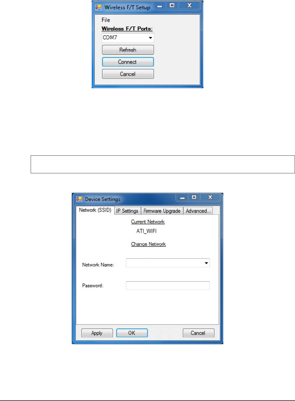
Figure3.2—WirelessF/TSetupprogram
3. Select the COM port corresponding to your Wireless F/T. If you have more than one device connected,
you can use Windows Device Manager to differentiate between them. You may need to press the
“Refresh” button if your device was just connected to the PC or is still booting up. When you have
selected the appropriate device, press the “Connect” button.
4. If your device is not already connected to the appropriate network, you can use the “Network (SSID)”
tab to select from a list of networks the device found while powering up. If your network does not appear
on the list, you can still type it in manually. If your network is password-enabled, you may enter that
here as well.
NOTICE: The Wireless F/T will not connect to the new network until the device is reset.
Figure3.3—Network(SSID)Settings
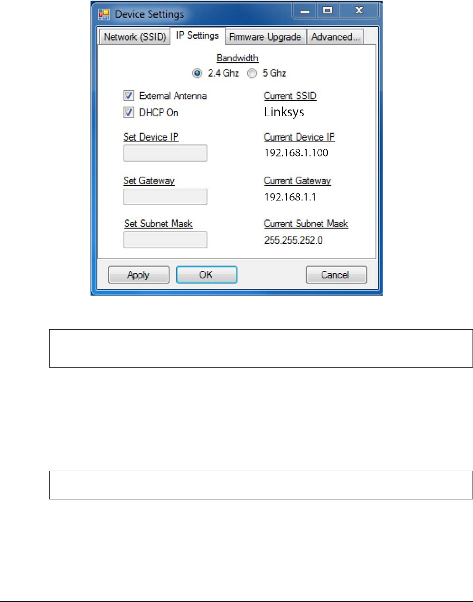
5. Obtain the following information from your network administrator: IP Address to use for the unit,
Subnet Mask, Default Gateway, SSID, and whether the Wi-Fi network operates on the 2.4 or 5 gigahertz
spectrum. You may not need all of this information if your device operates on DHCP.
Wireless F/T Installation and Operation Manual
Document #9620-05-Wireless FT-03
Pinnacle Park • 1031 Goodworth Drive • Apex, NC 27539 USA • Tel: +1.919.772.0115 • Fax: +1.919.772.8259 • www.ati-ia.com • Email: info@ati-ia.com
16
6. Select the “IP Settings” tab in the setup program and enter the appropriate information from step #5, as
below. Note that in this example DHCP is enabled, so editing the Device IP, Gateway, and Subnet mask
settings is not necessary.
Figure3.4—IPSettings
7. When you have made all the appropriate changes to the device settings, press the “OK” button to apply
the changes to the connected WNet unit and close the window.
NOTICE: The Changes will not take effect until AFTER the Wireless F/T has been reset. Do this
by pressing the power button on the side of the device for two seconds to power off. Press it
again to power up.
3.5 InstallingtheWirelessF/TJavaDemoApplicationonaPC
The following steps are provided to install the Wireless F/T Java Demo application on a PC.
1. Remove the WNet software CD from the package and insert it into the CD drive on your computer or
visit our website (http://www.ati-ia.com/library/download.aspx) and locate the WirelessFTJavaDemo.jar
le.
2. Copy or download the WirelessFTJavaDemo.jar le to the directory desired.
NOTICE: Java version 1.7 or later must be installed on the PC, if not visit http://java.com/en/ to
download and install the latest version of Java.
Wireless F/T Installation and Operation Manual
Document #9620-05-Wireless FT-03
Pinnacle Park • 1031 Goodworth Drive • Apex, NC 27539 USA • Tel: +1.919.772.0115 • Fax: +1.919.772.8259 • www.ati-ia.com • Email: info@ati-ia.com
17
3.6 StartingtheWirelessF/TJavaDemoApplication
Locate the WirelessFTJavaDemo.jar le in windows explorer and double click on it. The Initial screen will
appear.
Figure3.5—Initial Screen
Wireless F/T Installation and Operation Manual
Document #9620-05-Wireless FT-03
Pinnacle Park • 1031 Goodworth Drive • Apex, NC 27539 USA • Tel: +1.919.772.0115 • Fax: +1.919.772.8259 • www.ati-ia.com • Email: info@ati-ia.com
18
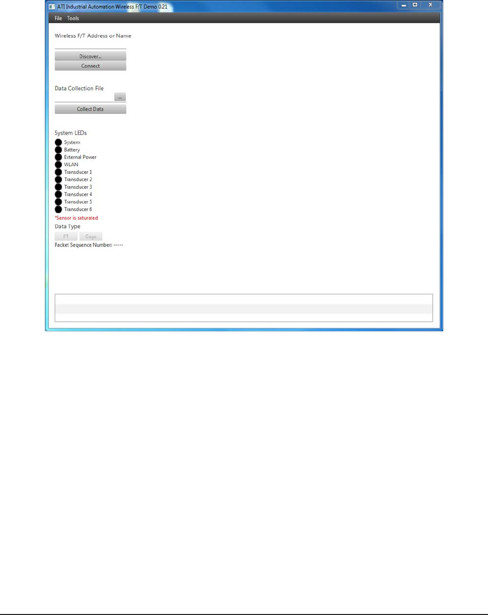
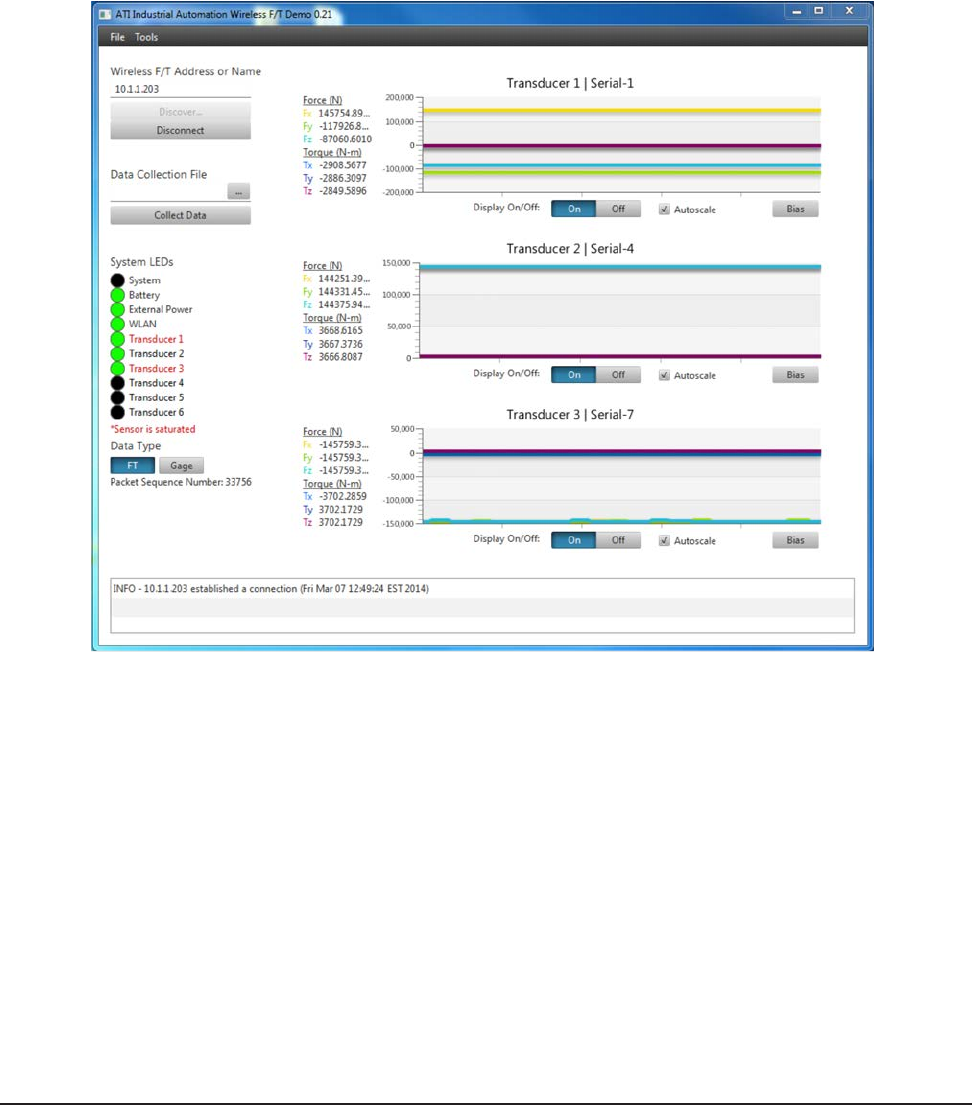
3.7 EstablishingaConnectiontotheWirelessF/TandMonitoringData
To establish a connection to the Wireless F/T, enter the IP address from the Section 3.4—Initial
Conguration that was designated for the Wireless F/T Unit into the “Wireless F/T Address or Name” eld.
If you don’t know the IP Address, you can press the “Discover…” button to nd which devices are currently
on the network. Once you have selected your Wireless F/T, press the “Connect” button. The application will
immediately begin displaying streaming data from the Transducers connected to the Wireless F/T Unit. The
LED status from the Wireless F/T unit will also be displayed graphically and an on screen log of the error
messages is displayed at the bottom of the screen.
Figure3.6—EstablishaConnection
The data type displayed can be switched from FT Data to raw Gage data by clicking the corresponding
buttons. The Bias buttons for each transducer will set the current load level as the new zero point. If the
maximum overload value of a transducer is exceeded, the demo program will display red text for the
transducer which exceeded its max value (i.e. became “saturated”).
Wireless F/T Installation and Operation Manual
Document #9620-05-Wireless FT-03
Pinnacle Park • 1031 Goodworth Drive • Apex, NC 27539 USA • Tel: +1.919.772.0115 • Fax: +1.919.772.8259 • www.ati-ia.com • Email: info@ati-ia.com
19
3.8 Data Collection
There are two ways data can be stored, data can be collected and stored on a le on a PC or network
directory or it can be collected and stored on the customers MicroSD™ card plugged into the Wireless F/T
unit.
3.8.1 CollectingandStoringDataonaMicroSD™ Card
To collect and store data on a MicroSD™ card ..........
Figure3.7—Sample F.dat Data File
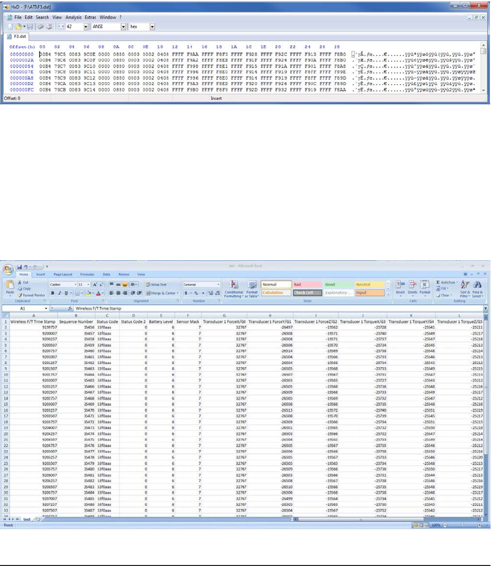
3.8.2 CollectingandStoringDataonaPCorNetworkFile
To collect data to a le, enter the path and le name or click the “…” button to the left of the eld
and select an existing le (or enter the name of a new le). Click the “Collect Data” button to
begin collecting data. Once you have the desired amount of data, click the “Stop” button to stop
collecting data.
The measurement data is stored in comma-separated value format (CSV) so it can be read by
spreadsheets and data-analysis programs. Name your le with a .CSV extension. If you are
planning on collecting large amounts of data, it is a good idea to understand any limitations your
spreadsheet or data analysis program may have on the number of rows it can work with.
Figure3.8—Sample CSV Data File Opened in MS Excel
Wireless F/T Installation and Operation Manual
Document #9620-05-Wireless FT-03
Pinnacle Park • 1031 Goodworth Drive • Apex, NC 27539 USA • Tel: +1.919.772.0115 • Fax: +1.919.772.8259 • www.ati-ia.com • Email: info@ati-ia.com
20
4. InstallingtheTransducer
Information on the environment, mounting the transducer, interface plate design, and routing the transducer cable
can be found in the F/T Transducer Installation and Operation manual (9620-Transducer Section). The transducer
must be monitored during installation for gage saturation errors. Refer Section 3.7—Establishing a Connection to
the Wireless F/T and Monitoring Data to monitor the transducer during installation.
CAUTION: Do not exceed the single-axis overload value of the transducer. Smaller
transducers can easily be irreparably damaged by apply small loads using tools (moment arm
increases applied loads) when mounting the transducer. Always monitor the transducer using
the demo application for Gage saturation errors during installation. Stop applying force to the
transducer and wait until the error clears to continue installation. If error does not clear, it may
indicate loss of power or the overload value has been exceeded.
Mounting Fasteners (Supplied by User)
Robot or other Device with User
designed interface plate attached
Mini or Nano
Transducer
Tool
Mounting fasteners
(Supplied by User)
Computer Running Demo Application

Wireless F/T Installation and Operation Manual
Document #9620-05-Wireless FT-03
Pinnacle Park • 1031 Goodworth Drive • Apex, NC 27539 USA • Tel: +1.919.772.0115 • Fax: +1.919.772.8259 • www.ati-ia.com • Email: info@ati-ia.com
21
5. Command Interface
The WNet unit must be installed, setup and congured prior to using any command interfaces. Refer to Section 3—
Installation for Installation, setup, and conguration of the WNet unit.
5.1 Communication Interfaces
The Wireless F/T can be setup and congured using a text-based command prompt console interface.
The Console Interface can be accessed two ways:
• Commands can be sent over the USB Connection over the wireless connector as a virtual serial port
• Telnet server listening on TCP Port 23
5.2 UPD Interface
The WNET unit listens on UDP port 49152 for commands. Any streaming UDP packets are sent to the
current Destination IP address until a UDP command is received. When the WNET unit receives a UDP
command from any IP address, the UDP packets are sent to whichever port the request came from.
The UDP server uses binary format for commands and responses. All multi-byte values use big-endian,
which is the same as network order.
5.3 UDP Command Format
All UDP commands to the WNET unit have the following format:
Table 5.1—UDP Command Format
Field Name Format Length(bytes) Comments
length unsigned short 2 Total length of this message, including CRC
sequence unsigned char 1 Sequence number. Used to identify missing
messages.
command unsigned char 1 Command number
payload unsigned char(s) length - 6 Command operands (if any)
crc unsigned short 2 See Appendix A – UDP Command CRC
Calculation, for details
This format can be rendered into C as:
struct udp_RecvFrame_S
{
unsigned short length; // Total length of this message
unsigned char sequence; // sequence number of this message
unsigned char command; // command number
unsigned char parameters[0]; // command operands
} __attribute__ ((__packed__));
These commands are currently implemented:
Table 5.2—Current Command Implementation
Number Name Comments
1 Start streaming Start streaming for either a xed or unlimited number of
packets
2 Stop streaming Stops streaming
3 Set packet transmission
rate Sets packet transmission rate. All transducers use the
same rate.
4 Ping Sends a no-payload Pong response back to the sender.

Wireless F/T Installation and Operation Manual
Document #9620-05-Wireless FT-03
Pinnacle Park • 1031 Goodworth Drive • Apex, NC 27539 USA • Tel: +1.919.772.0115 • Fax: +1.919.772.8259 • www.ati-ia.com • Email: info@ati-ia.com
22
5.4 Commands
These commands are available to any user, including commands to enter authenticated user and technician
user modes. All users can read any information about the system, including values that only authenticated
or technician users can write to.
H, HELP, or “?”
These commands print a summary of the Console commands supported by the WNet unit.
A [S] => ADC Single read (Analog Board)
This command reads the ADC converters from the Analog Board one time, and prints the results. For
example:
Tr Ch ADC-Raw
-- -- -------
1 0 -12976
1 1 -25950
1 2 -31035
1 3 0
1 4 0
1 5 0
2 0 -12971
2 1 -25940
2 2 -31024
2 3 0
2 4 0
2 5 0
3 0 -12961
3 1 -25920
3 2 -31020
3 3 0
3 4 0
3 5 0
AD => read all processor analog inputs
This command reads the processor analog inputs (Digital Board) and prints the results. For example:
Pin Voltage
--- -------
PD7 2.037
PE2 2.407
PE3 2.409
PE4 2.237
PE5 2.233
PE6 2.141
Temperature 33*C
ADCBW [FULL | 1/4] => set ADC bandwidth
This command selects the bandwidth for low-pass lter to either FULL or 1/4. Refer to the Selectable Low-
Pass Filter section in the ADC data sheet for details. For ADC testing only.
1/4 → 1/4 of bandwidth, uses an additional series resistor to further
bandwidth limit the noise. Maximum throughput must also be reduced to ¼.
FULL → full bandwidth

Wireless F/T Installation and Operation Manual
Document #9620-05-Wireless FT-03
Pinnacle Park • 1031 Goodworth Drive • Apex, NC 27539 USA • Tel: +1.919.772.0115 • Fax: +1.919.772.8259 • www.ati-ia.com • Email: info@ati-ia.com
23
ADCDEL [1 -> 2000] => set minimum ADC conversion time in 12.5 nS units
This command sets the conversion delay time for the ADCs on the Analog Board when samples are being
read from the same physical ADC. Each count = 1 / 80,000,000 second = 12.5 nS. If the delay is too short,
the analog measurements will have additional noise. If the delay is too long, time is wasted. Because
sampling from multiple transducers is interleaved, this value usually matters only if you reading samples
from a single Transducer. For ADC testing only.
ADCINCC [0 -> 7] => set the ADC Input Channel Conguration
This command controls the input channel conguration, which consists of the selection of pseudo bipolar,
pseudo differential, pairs, single-ended, or temperature sensor. Refer to the Input Congurations section
of the ADC data sheet for details. Note that the rmware will automatically convert unipolar to bipolar as
needed after each sample is read.
0. Bipolar differential pairs; INx− referenced to VREF/2 ± 0.1 V.
1. “
2. Bipolar; INx referenced to COM = VREF/2 ± 0.1 V.
3. Temperature sensor.
4. Unipolar differential pairs; INx− referenced to GND ± 0.1 V.
5. “
6. Unipolar, INx referenced to COM = GND ± 0.1 V.
7. Unipolar, INx referenced to GND.
ADCREF [0 -> 7] => set the ADC reference
This command controls the selection of internal, external, external buffered, and enabling of the ADC
on-chip temperature sensor. Refer to the Voltage Reference Output/Input section of the ADC data sheet for
details. For ADC testing only.
0. Internal reference, REF = 2.5 V output, temperature enabled.
1. Internal reference, REF = 4.096 V output, temperature enabled.
2. External reference, temperature enabled.
3. External reference, internal buffer, temperature enabled.
4. Undened
5. Undened
6. External reference, temperature disabled.
7. External reference, internal buffer, temperature disabled.
ANALOG [ON | OFF] => Turns Analog power (ANALOG_SHDN) on or off
This command controls the ANALOG_SHDN bit to the Analog Board.
ANTENNA [INT | EXT] => select internal or external antenna
This command selects whether the WLAN Module uses its internal antenna or an external antenna.
AUTOZ => Auto Zero the Active Transducer/Calibration
This command auto zeros the offset settings for the active Transducer and Calibration.
BAND [2.4 | 5] => select 2.4 or 5 GHz Band
This command selects whether the WLAN Module uses the 2.4 GHz or the 5 GHz band.

Wireless F/T Installation and Operation Manual
Document #9620-05-Wireless FT-03
Pinnacle Park • 1031 Goodworth Drive • Apex, NC 27539 USA • Tel: +1.919.772.0115 • Fax: +1.919.772.8259 • www.ati-ia.com • Email: info@ati-ia.com
24
BAT [ON | OFF | seconds] => Battery log on, off, toggle, or number of
seconds
This command turns a battery status log on and off. This log is used for testing the operation of the battery,
the Battery Charger, and the Gas Gage. A log entry is generated once per second. The log records the
following data items:
a. day and time since last system restart
b. charging voltage, as measured by the processor (at VPROG = PE3)
c. battery voltage, as measured by the Gas Gauge (at SENSE-)
d. Gas Gage Accumulated Charge Register (Ah)
e. USB power present ag (yes or no)
f. USB Battery Charger Detect (yes or no)
g. generated battery level (0 to 10)
h. Basis of the battery charge estimate method, voltage or current
i. Battery Charger status message
j. USB current limit USBILIM (mA)
k. battery temperature (°C)
l. CPU temperature (°C)
m. Gas Gauge temperature (°C)
n. ADC temperature for each powered Transducer (°C).
Day-Time VPROG GGVolt Charge:Ah USBPwr USBBCD BatLvl Based BatteryChargerStatus USBILIM Batt*C CPU*C GG*C T4*C T5*C T6*C
-------- ----- ------ --------- ------ ------ ------ ----- -------------------- ------- ------ ----- ---- ---- ---- ----
0-18:42:43 0.000 3.806 1.443 No No 6 Volt ChargerOff 100 -19.0 39.8 37.5 25.0 24.8 27.2
0-18:42:44 0.000 3.806 1.443 No No 6 Volt ChargerOff 100 -19.0 39.8 37.5 25.1 24.7 27.2
0-18:42:45 0.000 3.806 1.443 No No 6 Volt ChargerOff 100 -19.0 39.9 37.5 25.1 24.7 27.2
0-18:42:46 0.000 3.806 1.443 No No 6 Volt ChargerOff 100 -19.0 39.9 37.5 24.9 24.7 27.2
0-18:42:47 0.000 3.802 1.443 No No 6 Volt ChargerOff 100 -19.0 39.9 37.5 25.0 24.7 27.2
0-18:42:48 0.000 3.802 1.443 No No 6 Volt ChargerOff 100 -19.0 39.9 37.5 24.9 24.7 27.2

Wireless F/T Installation and Operation Manual
Document #9620-05-Wireless FT-03
Pinnacle Park • 1031 Goodworth Drive • Apex, NC 27539 USA • Tel: +1.919.772.0115 • Fax: +1.919.772.8259 • www.ati-ia.com • Email: info@ati-ia.com
25
BC => print all Battery Charger registers
This command prints all Battery Charger registers in a decoded format. For example:
BC: 0 = 60 DISABLE_INPUT_UVCL = Enabled
EN_BAT_CONDITIONER = Enabled > 60*C
LOCKOUT_ID_PIN = Autonomous Start-up Disabled
USBILIM = 100 mA max
BC: 1 = 20 PRIORITY = Wall Input Prioritized
TIMER = 8 Hr or C/x indication
WALLILIM = 100 mA max
BC: 2 = fe ICHARGE = 100 % => 2238 mA with RPROG = 536 Ohms
CXSET = 2 % => 44 mA
VFLOAT = 4.20 V
BC: 3 = 03 CHARGER_STATUS = Charger Off
ID_PIN_DETECT = No Detection: We are USB OTG-B peripheral
OTG_ENABLED = Step-Up Switching Regulator Inactive
NTCSTAT = too cold: < 0*C
LOWBAT = not meaningful
BC: 4 = 00 EXT_PWR_GOOD = Battery Power Only
USBSNS_GOOD = Voltage Invalid
WALLSNS_GOOD = Voltage Invalid
AT_INPUT_ILIM = Input Current Limit Inactive
INPUT_UVCL_ACTIVE = Input UVCL Inactive
OVP_ACTIVE = No Fault
OTG_FAULT = No Fault
BAD_CELL = No Fault
BC: 5 = ff NTCVAL Temperature = 127 => -19*C
NTC_WARNING = Too Warm or Too Cold to Charge
BC: 6 = 00 ENABLE_CHARGER_INT = Disabled
ENABLE_FAULT_INT = Disabled
ENABLE_EXTPWR_INT = Disabled
ENABLE_OTG_INT = Disabled
ENABLE_AT_ILIM_INT = Disabled
ENABLE_INPUT_UVCL_INT= Disabled
REQUEST_OTG = Step-Up Voltage Regulator Automatic or Disabled
BC [reg 0 -> 7] [hex byte] => write a Battery Charger register
This command allows you to modify any writable Battery Charger register.
BIAS [* | Transducer 1 -> 6] [OFF] => Set Bias on selected Transducer
This command allows you to set (or turn off) the bias on any or all Transducers.
BRIGHT [0 -> 100%] => Set Analog Board LED brightness
This command sets the brightness level of all LEDs on the Analog Board as a group. Brightness ranges from
0% to 100%.
C => Exit Continuous Mode
The continuous mode commands are provided as a test mode for the Analog Board. This command exits the
continuous mode.
C [A] [channels 012345678 any combination ordered list]
This command will cause the ADC input from the selected channels (for the Active Transducer) to be
printed continuously as fast as possible in the order requested.
C [D] [DAC 0 -> 7]
This command causes the selected DAC (for the Active Transducer) to be written continuously.

Wireless F/T Installation and Operation Manual
Document #9620-05-Wireless FT-03
Pinnacle Park • 1031 Goodworth Drive • Apex, NC 27539 USA • Tel: +1.919.772.0115 • Fax: +1.919.772.8259 • www.ati-ia.com • Email: info@ati-ia.com
26
C [E] [EEPOT 0 -> 5]
This command causes the selected EEPOT output (for the Active Transducer) to be written continuously.
CAL => View Active Transducer/Calibration
This command allows you to view the Calibration Matrix for the Active Transducer and Calibration. This
includes all of its associated parameters. For example, in a test system this command printed the following
report:
Tr Cal Gain Offset Row G0 G1 G2 G3 G4 G5 Properties
-- --- ---- ------ --- -- -- -- -- -- -- ----------
1 0 0 32768 0 Fx 1 0 0 0 0 0 Serial: Serial-1
1 0 0 32768 1 Fy 0 1 0 0 0 0 Date: 1970/01/01
1 0 0 32768 2 Fz 0 0 1 0 0 0 Part: Part-1
1 0 0 32768 3 Tx 0 0 0 1 0 0 Force: 12 counts/N
1 0 0 32768 4 Ty 0 0 0 0 1 0 Torque: 34 counts/N
1 0 0 32768 5 Tz 0 0 0 0 0 1 Mult: OFF
1 0 MaxRatings:
1 0 0 0 0 0 0 0
CAL [MATRIX] [Row: 0 -> 5] [Gage: 0 -> 5] [oat-values] => Change Active
Matrix element(s)
This command allows you to modify a multiple elements of the active calibration matrix. You can initialize
an entire matrix by typing CAL MAT 0 0 followed by 36 values. Array overow is checked so that you
cannot exceed the limits of the matrix.
CAL [GAIN ] [* | Row: 0 -> 5] [0 -> 1023] => Change Active gain
This command allows you to set the gain for any or all of the 6 strain gages. This command operates on the
Active Transducer and Active Calibration.
CAL [OFFSET] [* | Row: 0 -> 7] [0 -> 65535] => Change Active offset
This command allows you to set the offset for any or all of the 6 strain gages, and also the two unused
channels 6 and 7. This command operates on the Active Transducer and Active Calibration.
CAL [MAX] [Row: 0 -> 5] [oat-value] => Set Max Rating value
This command allows you to set any of the 6 oating-point Max Rating values.
CAL [SERIAL] [10-character string] => Change Active serial number
This command allows you to set the serial number associated with the active calibration.
CAL [DATE] [12-character string] => Change Active date
This command allows you to set the date associated with the active calibration.
CAL [PART] [32-character string] => Change Active part number
This command allows you to set the part number associated with the active calibration.
CAL [FORCE] [integer-value] [10-byte string] => Set Force Counts &
Units
This command allows you to set the Force Counts and Force Units associated with the active calibration.
CAL [TORQUE] [integer-value] [20-byte string] => Set Torque Counts &
Units
This command allows you to set the Torque Counts and Torque Units associated with the active calibration.
CAL [MULT] [*] [ON | OFF] => Matrix Multiply on/off
This command allows you to turn matrix multiplication on and off for the Active (or all) Transducers. This
command applies only to the active calibration of each Transducer.
CPLD [ON | OFF] => Turns CPLD Chip Select on or off
This command allows you to set the CPLD JTAG Chip Select bit PD7. This command is for board test
purposes only. If this bit is left on, no other SSI0 communications will work.

Wireless F/T Installation and Operation Manual
Document #9620-05-Wireless FT-03
Pinnacle Park • 1031 Goodworth Drive • Apex, NC 27539 USA • Tel: +1.919.772.0115 • Fax: +1.919.772.8259 • www.ati-ia.com • Email: info@ati-ia.com
27
TRANS [Transducer 1 -> 6] => Set Active Transducer
This command allows you to change the active Transducer. It will also show you the Active Calibration for
each Transducer, and which Transducer is currently active.
Tr Active-Calibrations
-- -------------------
1 0 <-- Active Transducer
2 0
3 0
CALIB [Calibration 0 -> 2] => Set Active Calibration
This command allows you to change the active Calibration. It will also show you the Active Calibration for
each Transducer, and which Transducer is currently active.
Tr Active-Calibrations
-- -------------------
1 0 <-- Active Transducer
2 0
3 0
G [* | channel 0 -> 5] [gain 0 -> 1023] => Change Active Gain
This command allows you to change the gain for any or all of the 6 strain gages. This command is a
shorthand version of CAL GAIN. This command operates on the Active Transducer and Active Calibration.
O [* | channel 0 -> 7] [offset 0 -> 65535] => Change Active Offset
This command allows you to change the offset for any or all of the 6 strain gages, and also the two unused
channels 6 and 7. This command is a shorthand version of CAL OFFSET. This command operates on the
Active Transducer and Active Calibration.
D [ON | OFF] => Dump packet on, off, or toggle
This command turns the dumping of outgoing UDP data packets to the console on and off.

Wireless F/T Installation and Operation Manual
Document #9620-05-Wireless FT-03
Pinnacle Park • 1031 Goodworth Drive • Apex, NC 27539 USA • Tel: +1.919.772.0115 • Fax: +1.919.772.8259 • www.ati-ia.com • Email: info@ati-ia.com
28
DEVICES => print device list
This command prints a list of all devices that communicate with the processor through I2C or SPI busses.
The list includes the device, the status, the bus, the bus address (when applicable), the Transducer associated
with the device (if any), and the device temperature (if available). For example, the DEVICES command
was issued in a system with only Analog Board 1, no Transducers connected, and the battery temperature
sensor disconnected. It produced the following report:
Device State Bus Ad Tr Temperature Voltage Current
------ ----- --- -- -- ----------- ------- -------
Processor Good 49.5 *C
SDCARD Good SSI0
Serial Flash Good SSI0
Battery NTC -19.0 *C
Battery Charger Good I2C0 64
Gas Gage Good I2C0 09 39.8 *C 3540 mV
WLAN Module Good SSI1
-------------------------------------------------------------------------------
Analog Board 1:
CPLD v.02 Good SSI0 3c
EEPROM Good SSI0 3b
ADC Good SSI0 20 4 27.4 *C 4936 mV 5 mA
DAC Good SSI0 24 4
EEPOT0 Good SSI0 25 4
EEPOT1 Good SSI0 26 4
EEPOT2 Good SSI0 27 4
ADC Good SSI0 28 5 27.2 *C 4884 mV 0 mA
DAC Good SSI0 2c 5
EEPOT0 Good SSI0 2d 5
EEPOT1 Good SSI0 2e 5
EEPOT2 Good SSI0 2f 5
ADC Good SSI0 30 6 30.1 *C 4888 mV 0 mA
DAC Good SSI0 34 6
EEPOT0 Good SSI0 35 6
EEPOT1 Good SSI0 36 6
EEPOT2 Good SSI0 37 6
DESTIP [n.n.n.n] => Set Destination IP
This command sets the destination IP address for outgoing UDP data packets. Note that this IP address will
only stay in effect until modied, either by this command again, or by the receipt of a UDP command to
send packets to some other IP address.

Wireless F/T Installation and Operation Manual
Document #9620-05-Wireless FT-03
Pinnacle Park • 1031 Goodworth Drive • Apex, NC 27539 USA • Tel: +1.919.772.0115 • Fax: +1.919.772.8259 • www.ati-ia.com • Email: info@ati-ia.com
29
EEPOT => print resistance-tolerance & end-to-end resistance of all
EEPOTs
This command prints the resistance tolerance and end-to-end resistance of all powered EEPOTs on the
Analog Board. For example:
>eepot
Tr Chip Raw Tolerance(%) Resistance(K-Ohms)
-- ---- --- ------------ ------------------
1 0 810b 1.042 25.260
1 1 8582 5.507 26.376
1 2 8522 5.132 26.283
2 0 809e 0.617 25.154
2 1 8507 5.027 26.256
2 2 80d6 0.835 25.208
3 0 806f 0.433 25.108
3 1 854f 5.308 26.327
3 2 82ed 2.925 25.731
EEPOT TEST [Transducer 1 -> 6] [Chip 0 -> 2] [24-bit command] => Send
command to selected EEPOT & see the response
This command allows you to send any arbitrary command to an EEPOT and see the response. For possible
commands please consult the ADN2850 data sheet, under “Theory of Operation”. For example, to read the
EEMEM content from Transducer 1, Chip 0, memory location 15:
>eepot test 1 0 0x9f0000
Tr=1 Chip=0 Tx=9f0000 Rx=9f810b
EEPOT DUMP => Dump the memory of all EEPOTs
This command allows you to dump the memory of all EEPOTs in a system. This includes both RDACs and
the 16 EEMEM locations. For example:
>eepot dump
Tr Ch DAC0 DAC1 0 1 2 3 4 5 6 7 8 9 10 11 12 13 14 15
-- -- ---- ---- - - - - - - - - - - -- -- -- -- -- --
1 0 0000 0005 0200 0200 0007 0000 0000 0000 0000 0000 0000 0000 0000 0000 0000 0000 0000 810b
1 1 0003 0004 0200 0200 0000 0000 0000 0000 0000 0000 0000 0000 0000 0000 0000 0000 0000 8582
1 2 0002 0001 0200 0200 0000 0000 0000 0000 0000 0000 0000 0000 0000 0000 0000 0000 0000 8522
2 0 0000 0000 0200 0200 0000 0000 0000 0000 0000 0000 0000 0000 0000 0000 0000 0000 0000 809e
2 1 0000 0000 0200 0200 0000 0000 0000 0000 0000 0000 0000 0000 0000 0000 0000 0000 0000 8507
2 2 0000 0000 0200 0200 0000 0000 0000 0000 0000 0000 0000 0000 0000 0000 0000 0000 0000 80d6
3 0 0000 0000 0200 0200 0000 0000 0000 0000 0000 0000 0000 0000 0000 0000 0000 0000 0000 806f
3 1 0000 0000 0200 0200 0000 0000 0000 0000 0000 0000 0000 0000 0000 0000 0000 0000 0000 854f
3 2 0000 0000 0200 0200 0000 0000 0000 0000 0000 0000 0000 0000 0000 0000 0000 0000 0000 82ed
FACTORY => Restore all calibrations and IP settings to factory defaults
This command restores all parameters, calibrations, and IP settings to the factory defaults. Use with caution,
as this command also erases the parameters in serial ash.
FCLOSE => Close all les
This command closes all les in the serial ash le system. The le system is saved to serial ash, and can
now survive a processor reset.
FDEL [lename] => File delete
This command deletes the specied le in the serial ash le system. The le system is saved to serial ash,
and can now survive a processor reset.

Wireless F/T Installation and Operation Manual
Document #9620-05-Wireless FT-03
Pinnacle Park • 1031 Goodworth Drive • Apex, NC 27539 USA • Tel: +1.919.772.0115 • Fax: +1.919.772.8259 • www.ati-ia.com • Email: info@ati-ia.com
30
FDIR => File System directory
This command prints the directory of the serial ash le system. For example:
>fdir
File-name Length Attr Cluster CRC
--------- ------ ---- ------- ---
abc 52 fffb 7 963d
123 20 fffb 8 3444
abcdef 26 fffb 9 44fe
3 File(s) 98 bytes 2,056,192 bytes free
FDUMP [lename] => File dump
This command prints the contents of the specied le in hex and characters. For example:
>fdump abc
000000 6162 6364 6566 6768 696a 6b6c 6d6e 6f70 abcdefghijklmnop
000010 7172 7374 7576 7778 797a 4142 4344 4546 qrstuvwxyzABCDEF
000020 4748 494a 4b4c 4d4e 4f50 5152 5354 5556 GHIJKLMNOPQRSTUV
000030 5758 595a WXYZ
FHEX [lename][hexdata] => File Write
This command allows you to enter data into a le as hex characters. Hex characters should be entered as
whole bytes only (i.e. only enter pairs of hex characters). New data is appended onto the end of existing
les. To write a brand-new le you must rst delete any existing le. After you are nished writing a le
use FCLOSE to make sure that everything is saved. This command is intended to be used for downloading
Processor and WLAN Module les to be used for upgrading the Wireless F/T unit. For example, this series
of commands:
>fhex abcdef abcdef
>fhex abcdef 0123456789
>fhex abcdef 00112233445566778899aabbccddeeff
creates the le:
>fdump abcdef
000000 abcd ef01 2345 6789 0011 0011 2233 4455 ....#Eg.....”3DU
000010 6677 8899 aabb ccdd eeff fw........
FWRITE [lename][data] => File Write.
This command allows you to enter data into a le as a text string. New data is appended onto the end of
existing les. This command is for testing the le system, as it is impossible to use it to enter binary images.
GATEIP [n.n.n.n] => Set the Gateway IP
This command sets the gateway IP address.

Wireless F/T Installation and Operation Manual
Document #9620-05-Wireless FT-03
Pinnacle Park • 1031 Goodworth Drive • Apex, NC 27539 USA • Tel: +1.919.772.0115 • Fax: +1.919.772.8259 • www.ati-ia.com • Email: info@ati-ia.com
31
GG => print all Gas Gage registers
This command prints all sixteen Gas Gage registers in a decoded format. For example:
GG: A = 0c Chip=LTC2942
Charge Alert High
Charge Alert Low
GG: B = fc Mode=auto PrescalerM=7 AL/CCpin=alert Shutdown=off
GG: C = 00
GG: D = 2b Charge accumulated = 43 => 0.009 Ah
GG: E = 29
GG: F = 8b Charge threshold high = 10635 => 2.259 Ah
GG: G = 04
GG: H = 27 Charge threshold low = 1063 => 0.225 Ah
GG: I = 89
GG: J = 04 Voltage at SENSE- = 35076 => 3.211 V
GG: K = ea Voltage threshold high = 59904 => 5.484 V
GG: L = 73 Voltage threshold low = 29440 => 2.695 V
GG: M = 87
GG: N = c0 Temperature at Gas Gage = 34752 => 45 *C
GG: O = 98 Temperature threshold high = 152 => 83 *C
GG: P = 63 Temperature threshold low = 99 => -41 *C
GG [reg A -> P] [hex byte] => write a Gas Gage register
This command allows you to modify any writable Gas Gage register.
IP => Display IP parameters
This command prints the communication parameters in a decoded format. For example:
>ip
Parameter Active Default MAC
--------- ------ ------- ---
SSID ATI_WIFI ATI_WIFI
DESTIP 0.0.0.0 0.0.0.0
GATEIP 10.1.1.20 192.168.0.1 00-20-a6-b4-5a-34
DEVIP 10.1.2.102 192.168.0.3 00-23-a7-0c-01-03
NET MASK 255.255.252.0 255.255.255.0
ANTENNA External
BAND 2.4 GHz
NET CHANNEL 1
NET DHCP On
NET MODE Normal CLIENT Mode
NET UDPACT BUFFER
TXPWR 2
Firmware Version 2.1.0 - Mar 17 2014 16:46:05
WLAN Module Version 2.4.0.1.5.4
WLAN: 18:50:35 Network parameters:
WLAN Connected Yes
Channel number 1
Network type Infra
Security level WEP
Open sockets 4
Sock Type MyPort RemPort RemIP
---- ---- ------ ------- -----
1 UDPout 49152 49152 0.0.0.0
2 UDPin 49152 0 0.0.0.0
3 TCPin 23 0 0.0.0.0
4 UDPin 51000 0 0.0.0.0

Wireless F/T Installation and Operation Manual
Document #9620-05-Wireless FT-03
Pinnacle Park • 1031 Goodworth Drive • Apex, NC 27539 USA • Tel: +1.919.772.0115 • Fax: +1.919.772.8259 • www.ati-ia.com • Email: info@ati-ia.com
32
LED [RED | GREEN] [ON | OFF | AUTO] => Controls indicated Digital Board
LED
This command allows you to manually control the Red and Green LEDs on the Digital Board for testing,
and then return the LEDs to automatic control.
LED1 [board: 0 | 1] [byte | AUTO] => Write byte to LED1 on the selected
Analog Board
This command allows you to manually control the LEDs on LED Port 1 of the selected Analog Board for
testing, and then return the LEDs to automatic control. For example:
>LED1 0 0x51
Board Port Value Mode
----- ---- ----- ----
0 LED1 51 TEST-output
0 LED2 22 AUTO-output
0 PWR 3f AUTO-output
LED2 [board: 0 | 1] [byte | AUTO] => Write byte to LED2 on the selected
Analog Board
This command allows you to manually control the LEDs on LED Port 2 of the selected Analog Board for
testing, and then return the LEDs to automatic control. For example:
>LED2 0 0x51
Board Port Value Mode
----- ---- ----- ----
0 LED1 aa AUTO-output
0 LED2 51 TEST-output
0 PWR 3f AUTO-output
PWR Port [board: 0 | 1] [byte | AUTO] => Write byte to PWR on the
selected Analog Board
This command allows you to manually control either Analog Board PWR port for testing, and then return it
to automatic control. PWR with no operands gives you a report on the status of the power ports:
>pwr 0 0x0f
Board Port Value Mode
----- ---- ----- ----
0 LED1 aa AUTO-output
0 LED2 22 AUTO-output
0 PWR 0f TEST-output

Wireless F/T Installation and Operation Manual
Document #9620-05-Wireless FT-03
Pinnacle Park • 1031 Goodworth Drive • Apex, NC 27539 USA • Tel: +1.919.772.0115 • Fax: +1.919.772.8259 • www.ati-ia.com • Email: info@ati-ia.com
33
FILTER [* | Transducer 1 -> 6] [MEAN | MEDIAN | IIR] [taps | tc] => Set
lter type & number of taps or time constant
This command allows you to set the lter type and the number of taps in the lter that the ADC inputs
pass through for any or all Transducers. The default is 1 (no ltering). MEAN is a simple running mean,
which is a form of low-pass lter. MEDIAN is a simple running median, which is another form of low-pass
lter. Note that a 31-tap MEAN lter running in all 6 Transducers executes in about 65 µS, while a 31-tap
MEDIAN lter in all 6 Transducers executes in about 480 µS, on average. This means that the maximum
possible packet rate (RATE) is lower if you use a MEDIAN lter as compared to a MEAN lter of the
same size. If a number of taps is not given, the number of taps is not changed. For IIR lters only, the time
constant of the lter is the “number of taps” samples. Taps range from 1 to 32. Time Constants range from 1
to 32767. This command will also give you a report of the current lter settings:
Tr Filter Taps TC
-- ------ ---- --
1 MEAN 32
2 MEDIAN 31
3 MEDIAN 15
4 IIR 32
5 IIR 64
6 IIR 128
FILTER S
This command displays statistics on how long it is taking to generate packets. This includes the time that
ltering takes. For example:
>lter s
TimeConstant = 2048 Packet generation time mean = 37.163 uS stdev = 0.197 uS
LPF [* | Transducer 1 -> 6] [taps 1 -> 32] => Set MEAN low-pass ltering
& number of taps
This command allows you to enable a running-mean low-pass lter, along with its number of taps. This
is the lter that the ADC inputs pass through for any or all Transducers. The default is 1 (no ltering).
This command will also give you a report of the current lter settings. If a number of taps is not given, the
number of taps is not changed. This command is the equivalent of issuing:
FILTER [* | Transducer 1 -> 6] MEAN [taps 1 -> 32]
MYIP [n.n.n.n] => Set My IP
This command sets the IP address of this WNET unit.
NET AP => Display Access Points found in the last scan
This command displays any Access Points that were found during the last Scan. For example :
>net ap
# Ch Secur RSSI SNR NType MAC SSID
- -- ----- ---- --- ----- --- ----
1 1 WPA2 -39 -39 Infra 00-21-a7-a4-49-ff ATI_WIFI
2 6 WPA2 -69 -13 Infra 00-22-a8-c4-3a-34 ATI_WIFI
NET CHANNEL [1 -> 13 | 149 | 153 | 157 | 161 | 165] => Channel to use if
AP or GO
This command selects the channel number that the unit will use if it becomes an Access Point (AP) or a
WiFi Direct™ Group Owner (GO).
NET DHCP [ON | OFF] => DHCP on or off
This command turns DHCP support on and off.

Wireless F/T Installation and Operation Manual
Document #9620-05-Wireless FT-03
Pinnacle Park • 1031 Goodworth Drive • Apex, NC 27539 USA • Tel: +1.919.772.0115 • Fax: +1.919.772.8259 • www.ati-ia.com • Email: info@ati-ia.com
34
NET DNS [up to 90 characters] => Get IP address(es) of given URL
This command allows you to nd the IP address(es) associated with a given URL. It tells you if network that
you are connected to has connectivity to the wider internet. For example:
>net dns microsoft.com
WLAN: 03:16:39
## IP-Address
-- ----------
1 64.4.11.37
2 65.55.58.201
NET KEY [up to 64 characters] => Set encryption key
This command sets the network key (sometimes called PSK) that is used with WEP, WPA, and WPA2
encryption. For WEP it must be exactly 5 or 13 characters (direct WEP entry in hex is not supported). For
WPA and WPA2 it must be no more than 64 characters.
NET MASK [n.n.n.n] => Set Subnet Mask
This command sets the subnet mask. A subnet mask is a 32-bit mask that is used to determine what subnet
an IP address belongs to. If you AND a packet’s IP address with the subnet mask and the result is the same
as the original IP address, the IP address is in the local subnet. If the result is different from the original IP
address, the IP address is in some other subnet, so the packet must be sent to the gateway device for further
routing.
NET MODE [CLIENT | DIRECT] => Set Client or Direct operating mode
This command selects either client mode (connect to an existing WiFi™ access point) or WiFi Direct™
mode.
NET UDPACT [BUFFER | DROP] => Packet action during ow control
This command controls the action that the unit takes while the WLAN Module has told it to stop sending
packets.
a. BUFFER means that the unit will buffer data packets during the ow control period, and then send
them when it is possible to do so. Data will only be lost if the ow control period lasts longer than
available storage for the buffer. This mode minimizes missing data, and is preferred for data logging
applications.
b. DROP means that the unit will drop all data packets generated during the ow control period.
Packet transmission will resume at the end of the ow control event. This mode minimizes latency,
and is preferred for robotic control applications.

Wireless F/T Installation and Operation Manual
Document #9620-05-Wireless FT-03
Pinnacle Park • 1031 Goodworth Drive • Apex, NC 27539 USA • Tel: +1.919.772.0115 • Fax: +1.919.772.8259 • www.ati-ia.com • Email: info@ati-ia.com
35
PORTS => print list of all GPIO ports
This command prints a list of all GPIO ports of the processor. Each entry of the list contains the port, the bit
on that port (0 through 7), the purpose of the bit, the current value of the bit (either 0 or 1), the GPIOPCTL
setting for the bit (either GPIO or some peripheral device number), the direction of the port if it is GPIO
(either in or out), the strength of the port in mA, the pin-type, and any interrupts triggered from the pin. For
example:
Bit V Purpose GPIOPCTL Dir Strength Pin-Type GPIO-Interrupt
--- - ------- -------- --- -------- -------- --------------
PA0 1 UART0_RX 1 2 mA Push-pull, weak pull-up
PA1 1 UART0_TX 1 2 mA Push-pull
PA2 0 SPI0_CLK 1 8 mA Push-pull
PA3 1 SD_CS 1 Out 2 mA Push-pull
PA4 1 SPI0_MISO 1 2 mA Push-pull, weak pull-up
PA5 1 SPI0_MOSI 1 8 mA Push-pull
PA6 0 WLAN_RDY GPIO In 2 mA Push-pull, weak pull-up
PA7 0 PWM_Sync GPIO In 2 mA Push-pull
PB0 0 JTAG_ENA GPIO Out 2 mA Push-pull
PB1 0 LED_SYS GPIO Out 2 mA Push-pull
PB2 1 I2C0_CLK 1 2 mA Open-drain, weak pull-up
PB3 1 I2C0_SDA 1 2 mA Open-drain, weak pull-up
PB4 1 MODE_SEL0 GPIO Out 2 mA Push-pull
PB5 0 GPIO In 2 mA Analog comparator
PB6 0 BUTTON GPIO In 2 mA Push-pull, weak pull-down
PB7 0 GPIO In 2 mA Analog comparator
. . .
RATEADC [rate: 5 -> 4000 Hz] => Set ADC read rate
This command allows you to set the rate at which the ADCs are read. The default is 2500 Hz, or one
ADC read every 0.4 mS = 400 µS. Reading the ADCs more often results in more accurate ADC reads if
smoothing is in use, at the cost of using more compute time.
RATE [rate: 1 -> 2500 ADC reads] => Set packet transmit rate
This command allows you to set the rate at which UDP packets are sent to the destination IP address. The
rate is set in terms of multiples of the ADC read rate (see below). The default is to send one UDP packet
every 250 ADC reads. At this default rate, and at the 2500 Hz default ADC read rate one UDP packet is sent
every 100 mS (10 Hz).
The fastest packet rate that is useful in an application depends on:
a. The ADC read rate RATEADC.
b. The number of Transducers in the system.
c. Filter type and number of taps.
d. Matrix Multiply on or off.
e. If using UDP, any other wireless radio trafc and radio interference in your environment.
f. If using UDP, whether you are in BUFFER mode (minimizing dropouts) or DROP mode
(minimizing latency).
g. If using MicroSD™, the hardware characteristics of the particular MicroSD™ card that you are
using, especially its maximum write latency.
h. Your application’s tolerance for dropped packets.

Wireless F/T Installation and Operation Manual
Document #9620-05-Wireless FT-03
Pinnacle Park • 1031 Goodworth Drive • Apex, NC 27539 USA • Tel: +1.919.772.0115 • Fax: +1.919.772.8259 • www.ati-ia.com • Email: info@ati-ia.com
36
REDPINE => Switch to RedPine Console Mode. Exit with +++
This is a special mode that allows you to communicate with the RedPine Console. This is used during radio
frequency acceptance testing.
RESET => Reset processor
This command resets the processor. Use with caution, especially if you are accessing the console through
Telnet.
RESTIP => Restore all IP settings to factory defaults
This command restores all IP settings to the factory defaults. Any changes take effect with the next Join to
an Access Point.
RSSI => display RSSI from AP
This command displays the RSSI value (in dBm) for the signal from the device that the Module is connected
to, as measured by the Module. RSSI (Received Signal Strength Indicator) is a measurement of the power
present in a received radio signal. For example:
>RSSI
WLAN: 00:19:59 RSSI from ATI_WIFI using External antenna: -45 dBm
SAVEALL => Save all calibrations & IP settings to Serial Flash
This command saves all calibrations and IP settings to Serial Flash, so that they will survive a processor
reset.

Wireless F/T Installation and Operation Manual
Document #9620-05-Wireless FT-03
Pinnacle Park • 1031 Goodworth Drive • Apex, NC 27539 USA • Tel: +1.919.772.0115 • Fax: +1.919.772.8259 • www.ati-ia.com • Email: info@ati-ia.com
37
SD => print SDCARD device info
With no operands, this command prints a multitude of technical information about the SDCARD card. For
example:
SD: Card in
SD: Card type = V2
SD: CSD register:
CSD_STRUCTURE 1
SPEC_VERS 0
TAAC 1.0 mS
NSAC (clocks) 0
TRAN_SPEED 25.0 Mbit/s
CCC 5b5: CMD6 enabled
READ_BL_LEN (bytes) 512
READ_BL_LEN_PARTIAL 0
WRITE_BLK_MISALIGN 0
READ_BLK_MISALIGN 0
DSR_IMP 0
ERASE_BLK_EN 1
ERASE_SECTOR_SIZE 128
WP_GRP_SIZE 1
WP_GRP_ENABLE 0
DEFAULT_ECC 0
R2W_FACTOR 4
WRITE_BL_LEN (bytes) 512
WRITE_BL_PARTIAL 0
CONTENT_PROT_APP 0
FILE_FORMAT_GRP 0
COPY 1
PERM_WRITE_PROTECT 0
TMP_WRITE_PROTECT 0
FILE_FORMAT 0
ECC 0
C_SIZE 60,872
Sectors 62,333,952
Capacity (bytes) 31,914,983,424
SD: SD Status register:
DAT_BUS_WIDTH 1 bit
SECURED_MODE No
SD_CARD_TYPE Regular SD RD/WR Card
SIZE_OF_PROTECTED_AREA 0
SPEED_CLASS Class 4
PERFORMANCE_MOVE 2M bytes/second
AU_SIZE 4M bytes
ERASE_SIZE 11 AU
ERASE_TIMEOUT 1 seconds
ERASE_OFFSET 1 seconds
UHS_SPEED_GRADE < 10M bytes/second
UHS_AU_SIZE 0
SD: CMD6: Switch Functions:
Field Bits Select
----- ---- ------
Max Current 100 mA
Group 1 8001 0
Group 2 c001 0
Group 3 8001 0
Group 4 8001 0
Group 5 8001 0
Group 6 8001 0
Version 0
Misc 0000 0000 0000 0000 0000 0000
SD: OCR register: Ready CCS=1=SDHC Vdd: 2.7V to 3.6V
SD: CID register:
MID 03 = SanDisk
OID 5344 = SD
PNM SU32G
Rev 80
PSN 73bb8e
Date 6/2013

Wireless F/T Installation and Operation Manual
Document #9620-05-Wireless FT-03
Pinnacle Park • 1031 Goodworth Drive • Apex, NC 27539 USA • Tel: +1.919.772.0115 • Fax: +1.919.772.8259 • www.ati-ia.com • Email: info@ati-ia.com
38
SD [sector-1] [sector-n] => dump MicroSD sectors
If sector numbers are given (in hex) this command will dump the contents of the specied sectors on the
MicroSD This command is provided for MicroSD rmware testing only. For example, to dump the contents
of sector 0x300 (which appears to be part of a directory):
>sd 300
SD: Card in
SD: Card type = V2
SD: CSD:
Capacity (bytes) 1,015,808,000
Sectors 1,984,000
000000 2e20 2020 2020 2020 2020 2010 000b 238b . ...#.
000010 0a37 0a37 0000 238b 0a37 0200 0000 0000 .7.7..#..7......
000020 2e2e 2020 2020 2020 2020 2010 000b 238b .. ...#.
000030 0a37 0a37 0000 238b 0a37 0000 0000 0000 .7.7..#..7......
000040 4172 0069 006e 0067 0074 000f 0015 6f00 Ar.i.n.g.t....o.
000050 6e00 6500 7300 0000 ffff 0000 ffff ffff n.e.s...........
000060 5249 4e47 544f 7e31 2020 2010 000c 238b RINGTO~1 ...#.
000070 0a37 0a37 0000 238b 0a37 0300 0000 0000 .7.7..#..7......
000080 4170 0069 0063 0074 0075 000f 00c8 7200 Ap.i.c.t.u....r.
000090 6500 7300 0000 ffff ffff 0000 ffff ffff e.s.............
0000a0 5049 4354 5552 7e31 2020 2010 000e 238b PICTUR~1 ...#.
0000b0 0a37 0a37 0000 238b 0a37 0400 0000 0000 .7.7..#..7......
0000c0 416d 0075 0073 0069 0063 000f 009f 0000 Am.u.s.i.c......
0000d0 ffff ffff ffff ffff ffff 0000 ffff ffff ................
0000e0 4d55 5349 4330 7e31 2020 2010 000f 238b MUSIC0~1 ...#.
0000f0 0a37 0a37 0000 238b 0a37 0500 0000 0000 .7.7..#..7......
000100 4176 0069 0064 0065 006f 000f 000e 7300 Av.i.d.e.o....s.
000110 0000 ffff ffff ffff ffff 0000 ffff ffff ................
000120 5649 4445 4f53 7e31 2020 2010 0000 248b VIDEOS~1 ...$.
000130 0a37 0a37 0000 248b 0a37 0600 0000 0000 .7.7..$..7......
000140 4173 0079 0073 0074 0065 000f 0072 6d00 As.y.s.t.e...rm.
000150 0000 ffff ffff ffff ffff 0000 ffff ffff ................
000160 5359 5354 454d 7e31 2020 2012 0002 248b SYSTEM~1 ...$.
000170 0a37 0a37 0000 248b 0a37 0700 0000 0000 .7.7..$..7......
000180 0000 0000 0000 0000 0000 0000 0000 0000 ................
000190 => 0001ff same as above
SD [FORMAT] => Format MicroSD
This command allows you to format the MicroSD™ card. All existing data on the MicroSD™ card will be
lost. The command will ask you to verify that you want to format the disk before it actually deletes any data.
Any data streaming over the WLAN will be interrupted while the format is taking place.
SD [ON | OFF] => Control MicroSD power
This command allows you to control power to the MicroSD™ card. Issuing other MicroSD™ card
commands will also turn the MicroSD power back on. This command is provided for MicroSD rmware
testing only.
SDW [start] [data] => write MicroSD sector
This command writes the given data to the specied MicroSD sector. This command is provided for
MicroSD rmware testing only.
SCD [directory] => Similar to the standard CD command
This command allows you to display and change the path on the MicroSD.

Wireless F/T Installation and Operation Manual
Document #9620-05-Wireless FT-03
Pinnacle Park • 1031 Goodworth Drive • Apex, NC 27539 USA • Tel: +1.919.772.0115 • Fax: +1.919.772.8259 • www.ati-ia.com • Email: info@ati-ia.com
39
SDEL => [lename] => delete le(s), wild cards * and ? may be used
This command deletes the selected les in the current directory on the MicroSD. For example:
>sdel f2.dat
F2.DAT deleted
Files deleted: 1
SDIR => Print Directory
This command prints a directory of all les in the current path on the MicroSD. For example:
Directory of 0:/ATI
2010/01/01 00:06 <DIR> .
2010/01/01 00:06 <DIR> ..
2010/01/01 00:56 4 ATI.ini
2010/01/01 00:49 66,446,898 F2.dat
2010/01/01 01:21 20,995,230 F3.dat
2010/01/01 00:07 56,057,184 F4.dat
2010/01/01 00:08 6,677,154 F5.dat
2010/01/01 00:09 4,886,082 F6.dat
2010/01/01 00:09 3,938,868 F7.dat
2010/01/01 00:05 756 F8.dat
2010/01/01 00:05 68,586 F9.dat
2010/01/01 00:05 79,338 F10.dat
2010/01/01 00:05 61,530 F11.dat
2010/01/01 00:05 66,570 F12.dat
2010/01/01 00:02 1,188,993,882 F13.dat
2010/01/01 00:23 11,860,926 F14.dat
2010/01/01 00:14 66,858,426 F15.dat
2010/01/01 16:02 4,294,967,220 F16.dat
16 File(s) 5,721,958,654 bytes
2 Dir(s)
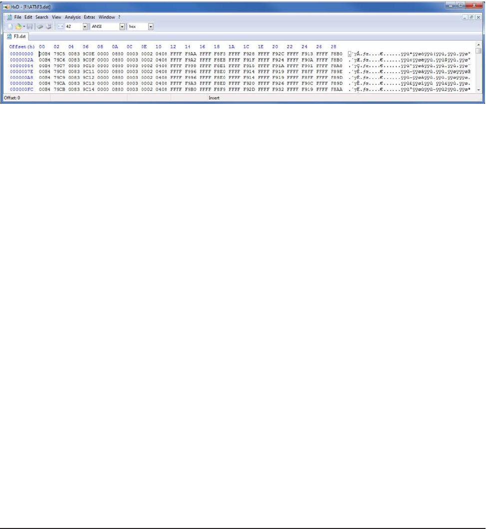
Wireless F/T Installation and Operation Manual
Document #9620-05-Wireless FT-03
Pinnacle Park • 1031 Goodworth Drive • Apex, NC 27539 USA • Tel: +1.919.772.0115 • Fax: +1.919.772.8259 • www.ati-ia.com • Email: info@ati-ia.com
40
SDREC [ON | OFF] => Stream packets to MicroSD: on, off, or toggle
This command streams data (in the standard packet format, which is also used for UDP packets) to the
MicroSD™ card. All data is placed in the \ATI subdirectory, which is created if it is not already present. The
le ati.ini is also created within this subdirectory if it is not already present. Each time that the SDREC ON
command is issued, a new le Fn.dat le is created. Note that n is the next sequential le number.
Note that the le system only supports le sizes up to 4 G bytes.
The data can be read by placing the MicroSD™ card into a computer that supports the FAT le system. A
Micro SD to USB adapter may be required.
When viewed with the HxD utility, data for a single transducer may look like:
Figure5.1—Fn.datleformat
Note that if an interruption occurs while this data is being written (such as the removal of the MicroSD™
card or the battery) the open le will generally lose any data written within the last two seconds. The
interruption may also cause lost le system clusters, which will reduce the storage capacity of the card.
As the WNET unit does not contain a le system repair utility, lost clusters may be repaired either by
formatting the card (using the SD FORMAT command, which will cause the loss of all data on the card), or
by putting the card into a computer and running the Scandisk utility. On Windows 7 machines this can be
done by opening Windows Explorer, right-clicking on the drive letter of the MicroSD™ card and selecting
Properties, clicking the Tools tab, pressing the Check Now… button, and the pressing Start.
SDUMP[lename] => File dump
This command prints a hex dump of the specied le on the MicroSD.
SF => print Serial Flash device info
This command prints information about the Serial Flash device. This command is provided for serial ash
rmware testing. For example:
SF: Maker = Silicon Storage Technology
SF: Device = SST25VF010A => 128K bytes
SF: Status = 00 BlockProtect = None
SFR [address] [length] => print Serial Flash memory of length given
This command prints Serial Flash memory starting at the given address for the given length. This command
is provided for serial ash rmware testing. For example, here we dump the rst calibration area for a unit
that has no calibrations saved:
>sfr 1000 2000
SF: 001000 ffff ffff ffff ffff ffff ffff ffff ffff ................
SF: 001010 => 002fff same as above
SFW [address] [byte] => write byte to Serial Flash address given
This command allows you to write a single byte to the Serial Flash. This command is provided for serial
ash rmware testing.

Wireless F/T Installation and Operation Manual
Document #9620-05-Wireless FT-03
Pinnacle Park • 1031 Goodworth Drive • Apex, NC 27539 USA • Tel: +1.919.772.0115 • Fax: +1.919.772.8259 • www.ati-ia.com • Email: info@ati-ia.com
41
SS [A] [012345678 any combination or order] => read specied ADC
channels once
This command reads the specied ADC channels once.
SS => repeats last SS command
This command repeats the last SS command, without the need to retype the whole thing.
SSI [ADC | DAC | EEPOT | PORTS | SDCARD | SF | WLAN] [bit rate: bits/
second] => Set selected SSI bit rate
This command allows you to view information about and set the bit rate for all devices that communicate
over an SSI port (SSI is the Stellaris name for SPI). Any new rate takes effect immediately. For example:
Device Rate(Hz) Pol Pha Format
------ -------- --- --- ------
ADC 10000000 0 0 Freescale
CPLD 10000000 0 0 Freescale
DAC 1000000 0 0 Freescale
EEPOT 1000000 0 0 Freescale
EEPROM 10000000 0 0 Freescale
PORTS 10000000 0 0 Freescale
SDCARD 10000000 0 0 Freescale
SF 10000000 0 0 Freescale
WLAN 10000000 0 0 Freescale
With an 80 MHz clock, the highest bit rates that are supported by the processor hardware are:
1. 40,000,000 Hz (no SPI peripherals work at this speed)
2. 20,000,000 Hz
3. 13,333,333 Hz
4. 10,000,000 Hz
5. 8,000,000 Hz
SSID [case-sensitive string] => Set SSID
This command allows you to view and set the SSID. The new SSID will be effective after the next Join to
an Access Point. An SSID is the name of a wireless local area network. SSIDs are case sensitive text strings.
The SSID is a sequence of alphanumeric characters (letters or numbers). SSIDs have a maximum length of
32 characters.
STACK => Print stack available message
This command allows you to view how much of the processor stack is free. Whenever a new low in stack
bytes free occurs that is less than 1024 bytes this message will also appear without the command being
typed. For example:
>stack
STACK: 1184 of 4096 bytes free
STATS => Print packet statistics, [0] to clear
This command prints how many total packets, dropped packets, the maximum length of event that have
occurred since power up or the last STATS 0 command in MicroSD writing (due to write latency) and UDP
packet transmitting (due to ow control), and the average length of event. For UDP packets this command
also prints the average ow control event duration, how many ow control events occurred, and how many
times the WLAN Module locked-up and had to be reset. For example:
>stats
00:03:54 CARD Packets: Generated= 200,678 Dropped= 0 Write Latency: Max= 92 mS Mean= 1.406 mS
00:03:54 WLAN Packets: Generated= 200,678 Dropped= 0 Flow Control: Max= 92 mS Mean= 11.178 mS Events= 2,278 Module: Lock-Ups= 0

Wireless F/T Installation and Operation Manual
Document #9620-05-Wireless FT-03
Pinnacle Park • 1031 Goodworth Drive • Apex, NC 27539 USA • Tel: +1.919.772.0115 • Fax: +1.919.772.8259 • www.ati-ia.com • Email: info@ati-ia.com
42
T [ON | OFF] => Transmit packet on, off, or toggle
This command turns the transmission of outgoing UDP data packets to the WLAN Module on and off.
TEST [* | Transducer 1 -> 6] [OFF | ZERO | DAC] => Set Self-Test mode on
selected Transducer(s)
This command sets the self test mode for the selected Transducers:
TESTSetting ADCInputforthisTransducerconnectedto:
OFF Normal sensor input
ZERO Zero signal (2.5V = 0x8000)
DAC DAC Channel 6 for this Transducer
Set DAC channel 6 output procedure for one Transducer:
a. Set active Transducer: TRANS [1 6]
b. Set DAC Channel 6 output: O 6 [value: 0 65535 or 0xFFFF]
This command generates a report of the self-test status of the unit:
>TEST 5 ZERO
Tr Self-test-mode
-- --------------
1 OFF
2 OFF
3 OFF
4 OFF
5 ZERO
6 OFF
TXPWR [0 | 1 | 2] => Set transmit power after next Join
This command allows you to set the WLAN Module’s transmit power. The power level change takes place
after the next Join to an Access Point.
Band 0 = low 1 = medium 2=high
GHz dBm +/- 1 mW dBm +/- 1 mW dBm +/- 2 mW
2.4 7 5 10 10 15 32
5 5 3 7 5 12 16

Wireless F/T Installation and Operation Manual
Document #9620-05-Wireless FT-03
Pinnacle Park • 1031 Goodworth Drive • Apex, NC 27539 USA • Tel: +1.919.772.0115 • Fax: +1.919.772.8259 • www.ati-ia.com • Email: info@ati-ia.com
43
USBILIM [value in mA] => set USB current limit
This command sets the USB Input Current Limit (USBILIM) value in Battery Charger Register 0. You must
enter an exact value from the following table:
Value
mA Meaning Notes
100 Max (USB Low Power) Default setting CLPROG1 and CLPROG2 shorted.
Refer to the Input Current Regulation section for
information when this register is modied by the
LTC4155.
500 Max (USB High Power)
600 Max
700 Max
800 Max
900 Max (USB 3.0)
1000 Typical
1250 Typical
1500 Typical
1750 Typical
2000 Typical
2250 Typical
2500 Typical
2750 Typical
3000 Typical
22.5 mA Max (USB Suspend)
0 Select CLPROG1 Default setting two CLPROG resistors. Refer to the
Input Current Regulation section for information when
this register is modied by the LTC4155.
USER => Switch to User Mode
This command switches the Console to User Mode.
WLAN [ON | OFF] => Turns WLAN Module power (WIFI_PWREN) on or off
This command controls the WIFI_PWREN bit to the WLAN Module on the Digital Board. The WLAN OFF
command also turns off transmission of the regular UDP data packet.
WFLOAD => Load WLAN Module, 2-le method
This command allows you to load the WLAN Module with new rmware using the shorter 2-le method.
This is the method that is normally used. This command takes about 5 minutes to execute. Before
committing to the WLAN Module update, this command checks to make sure that the necessary les
(WiSe_Con and WiSe_WLA) are present in the Serial Flash, have a termination record (so they are probably
complete), and have no checksum errors.
WFLOAD4 => Load WLAN Module, 4-le method
This command allows you to load the WLAN Module with new rmware using the longer 4-le method.
This longer method is necessary for WLAN Modules that have had the RF Test rmware loaded into them.
This command takes about 8 minutes to execute. Before committing to the WLAN Module update, this
command checks to make sure that the necessary les (WFU_Cont, WLAN_CON, WiSe_WLA, and WiSe_
Con) are present in the Serial Flash, have a termination record (so they are probably complete), and have no
checksum errors.

Wireless F/T Installation and Operation Manual
Document #9620-05-Wireless FT-03
Pinnacle Park • 1031 Goodworth Drive • Apex, NC 27539 USA • Tel: +1.919.772.0115 • Fax: +1.919.772.8259 • www.ati-ia.com • Email: info@ati-ia.com
44
WFLOADRF => Load WLAN Module, for RF testing
This command allows you to load the WLAN Module with new rmware for RF testing. This command
takes about 2 minutes to execute. Before committing to the WLAN Module update, this command checks
to make sure that the necessary les (WiSe_Con.t and WiSe_WLA.t) are present in the Serial Flash, have
a termination record (so they are probably complete), and have no checksum errors. These two les must
be loaded into the WNET unit, and then renamed by added the .t sufx to each le name before using this
command.
XPWR [* | Transducer: 1 -> 6] [ON | OFF| BRIDGE | AFE] => Transducer
power control
This command allows you to control the Analog Board power settings for each of the Transducers. The
choice for each Transducer is:
1. ON. The Analog Front End (AFE) for this Transducer (on the Analog Board) and the external
Transducer (BRIDGE) are fully powered.
2. OFF. The AFE and the external Transducer are off.
3. BRIDGE power only. The AFE is off and the external Transducer is on.
4. AFE power only. The AFE is on and the external Transducer is off.
The WNET reduces power surges by turning power on gradually. When you issue this command for a
Transducer:
1. If Transducer ON or BRIDGE-only was selected, and the Analog Power (ANALOG_SHDN bit
PF0) was off, Analog Power is turned on, and there is a 0.5 second delay.
2. If Transducer OFF was selected, and all Transducers are now off, Analog Power is turned off.
3. If Transducer ON was selected, power to the Transducer’s BRIDGE and AFE is turned on.
4. If Transducer OFF was selected, power to the Transducer’s BRIDGE and AFE is turned off.
5. If Transducer BRIDGE was selected, power to the Transducer’s BRIDGE is turned on and AFE
is turned off.
6. If the Transducer’s BRIDGE or AFE state changed to on, there is now a 0.5 second delay.
7. If the Transducer’s AFE state changed to on, the Transducer’s DAC and EEPOTs are now
written with their calibration values.
8. If the Transducer’s BRIDGE or AFE state changed to on, a Current Limit Reset is now
performed.
This command will also generate a report of the current Transducer power status. The Auto column is what
the software is commanding, based on the XPWR command. The Now column is what is actually going out
to the power port. If the columns are different, it is because direct test outputs to the Analog Board ports are
in use (see the LED1, LED2, and PWR commands).
Tr Auto Now
-- ---- ---
1 ON ON
2 ON ON
3 ON ON
4 ON ON
5 ON ON
6 ON ON
Analog power ON

Wireless F/T Installation and Operation Manual
Document #9620-05-Wireless FT-03
Pinnacle Park • 1031 Goodworth Drive • Apex, NC 27539 USA • Tel: +1.919.772.0115 • Fax: +1.919.772.8259 • www.ati-ia.com • Email: info@ati-ia.com
45
6. Maintenance
Under normal conditions, no special maintenance is necessary, however it is recommended that periodic inspections
be performed to assure long-lasting performance and to assure that unexpected damage has not occurred. Refer to
Section 6.1—Preventive Maintenance for a schedule and items that should be visually inspected at regular intervals.
Wireless F/T devices operating on battery power should be monitored periodically for battery status.
Spare parts are available from ATI Industrial Automation. Please call for recommendations.
6.1 Preventive Maintenance
The Wireless F/T is designed to provide a long life with regular maintenance. A visual inspection and
preventive maintenance schedule is provided in the Table 6.1. Assembly details are provided in Section 11—
Drawings.
Table 6.1—PreventativeMaintenanceChecklist
Repetitive motion Frequency InspectionSchedule
More than 1 per minute Weekly
Less than 1 per minute Monthly
Cabling
□ Visually inspect the power supply and transducer cabling for wear or damage. If wear or
damage is visible, replace cabling and adjust routing or protect cabling with a loose plastic
spiral wrap.
□ Visually inspect cable connection for looseness, tighten connection or replace cable as
needed
MountingFasteners
□ Inspect mounting fasteners, verify they are tight and have the proper torque.
6.2 BatteryRechargingandReplacement
The batteries can be charged internally using the USB port above the battery compartment or externally in a
battery charger.
6.2.1 ChargingBatteryInternally
The battery can be charged internally with the external power adapter included. A USB cable that
connects the external power adapter to the Wireless F/T. Note: The computer connected to the USB
port does not provide sufcient source to keep the battery charged.
6.2.2 ChargingBatteryExternally
The battery can be charged externally and swapped out while a second battery is charging. It will
result in a brief power-down condition.
1. Loosen the quarter-turn fastener on the battery compartment and open the door.
2. Slide the battery out and replace it with a fully charged battery.
3. Close the door and tighten the quarter-turn fastener.

Wireless F/T Installation and Operation Manual
Document #9620-05-Wireless FT-03
Pinnacle Park • 1031 Goodworth Drive • Apex, NC 27539 USA • Tel: +1.919.772.0115 • Fax: +1.919.772.8259 • www.ati-ia.com • Email: info@ati-ia.com
46
7. Troubleshooting
The system contains few components and provides trouble-free operation once properly installed. The following
table is provided to assist with troubleshooting the system.
Table 7.1—Troubleshooting
Symptom Possible Cause Correction
Nonexistent
or intermittent
communication
Low battery power Charge battery, (if battery does not retain a
charge replace battery).
Worn or damaged cabling Inspect and test power supply and transducer
cabling and replace as needed.
External power adapter failing or
not functioning
Replace external power adapter
Obstruction between Wireless
F/T and wireless access point Remove obstruction or reposition Wireless
F/T, or the wireless access point to obtain an
unobstructed environment
Wireless network component
failing or not functioning
Test components and replace as needed
Wireless F/T failing or not
functioning
Test Wireless F/T and replace as needed
Transducer not functioning Refer to the F/T Installation and Operation manual
for troubleshooting information.
Wireless status
indicator is
ashing red
This typically happens when
trying to transmit to a UDP
address that does not exist
8. Serviceable Parts
Description Part Number
Wireless F/T WNet-3 9105-WNET3
Wireless F/T WNet-6 9105-WNET6
Battery 5515-3.70000-01
External Battery Charger 9105-WNETEBC
Antenna 9105-WNETANT
Wireless F/T Power Supply, Wall Adapter Type 9105-WNETPS
USB A Male to USB B Male cable, 0.9m 9105-C-USAA-MINIB-0.9

Wireless F/T Installation and Operation Manual
Document #9620-05-Wireless FT-03
Pinnacle Park • 1031 Goodworth Drive • Apex, NC 27539 USA • Tel: +1.919.772.0115 • Fax: +1.919.772.8259 • www.ati-ia.com • Email: info@ati-ia.com
47
9. Specications
The specications section covers characteristic of the Wireless F/T device, other components such as transducer,
cabling may be found in the specic product manual on our website. Drawings may also be found in the product
catalog and on our website. 2-D and 3-D models are also available on our website.
Contact ATI for specic information and drawings regarding your installation. We encourage you to use our
applications department to review your designs and answer your questions.
9.1 WirelessCharacteristics
Wireless Local Area Network (WLAN) IEEE 802.11 b/g/n 2.4 GHz / 5.0 GHz
Typical Range (Antenna attached)
Ofce Type Environment 30 m (98 ft)
unobstructed environment 100 m (328 ft)
Note: Only certied with the antenna attached.
9.2 Power Requirements
Battery Power
Internal battery 3.7V Lithium-polymer rechargeable
Typical battery life (Max, streaming rate and transducers used)
WNet-3 2 hrs
WNet-6 1 hr
Power consumption 2A at 5 VDC
External power adapter 5VDC
9.3 PhysicalCharacteristics
Size
Wireless WNet-3 (Excluding Antenna & mating connectors) 156 mm x 82 mm x 19.7 mm
(6.15 in x 3.23 in x 0.775 in)
Wireless WNet-6 (Excluding Antenna & mating connectors) 156 mm x 82 mm x 33 mm
(6.15 in x 3.22 in x 1.3 in)
Antenna 100 mm (3.9 in)
Weight
Wireless WNet-3 0.6 lbs (0.27 kg)
Wireless WNet-6 0.6 lbs (0.27 kg)
Mounting See Section 13—Drawings
Operating ambient Temperature (Non-Charging) 0°C to +50°C (Note: battery runtime may
decrease above 35°C ambient).
Battery charging ambient temperature 0°C to +35°C
Storage ambient temperature -20°C to 45°C
Humidity 85% maximum, non-condensing

Wireless F/T Installation and Operation Manual
Document #9620-05-Wireless FT-03
Pinnacle Park • 1031 Goodworth Drive • Apex, NC 27539 USA • Tel: +1.919.772.0115 • Fax: +1.919.772.8259 • www.ati-ia.com • Email: info@ati-ia.com
48
10. RegulatoryInformation
10.1 FCC Statement
DeclarationofConformitywithFCCRulesforElectromagneticCompatibility
We, ATI Industrial Automation of 1031 Goodworth Drive, Apex, NC 27539, declare under our sole
responsibility that the Wireless Multi-Axis Force/Torque Transmitter models, WNET-NA-x, FTWN-NA-x,
comply with Part 15 of the FCC Rules. Operation is subject to the following two conditions: (1) this device
may not cause harmful interference, and (2) this device must accept any interference received, including
interference that may cause undesired operation.
IMPORTANT NOTICE:
Federal Communications Commission Notice
This equipment has been tested and found to comply with the limits for a Class A digital device, pursuant
to part 15 of the FCC Rules. These limits are designed to provide reasonable protection against harmful
interference when the equipment is operated in a commercial environment. This equipment generates, uses,
and can radiate radio frequency energy and, if not installed and used in accordance with the instruction
manual, may cause harmful interference to radio communications. Operation of this equipment in a
residential area is likely to cause harmful interference in which case the user will be required to correct the
interference at their own expense.
FCC Radiation Exposure Statement
The SAR limit for North America is 1.6 W/kg averaged over one gram of tissue. This product (FCC ID:
2ACKB-9105WNET) has also been tested against this SAR limit. The highest SAR value reported under
this standard during product certication for use when properly worn on the body is 1.04 W/kg.
This device was tested for typical body-worn operations with the back of the device kept 0mm from the
body. To maintain compliance with IC RF exposure requirements, use accessories that do not contain
metallic components in its assembly. The use of accessories that do not satisfy these requirements may not
comply with IC RF exposure requirements, and should be avoided.
Modications
Changes or modications not expressly approved by the party responsible for compliance could void the
user’s authority to operate the equipment.

Wireless F/T Installation and Operation Manual
Document #9620-05-Wireless FT-03
Pinnacle Park • 1031 Goodworth Drive • Apex, NC 27539 USA • Tel: +1.919.772.0115 • Fax: +1.919.772.8259 • www.ati-ia.com • Email: info@ati-ia.com
49
10.2 Canadian Compliance Statement
This device complies with Industry Canada licence-exempt RSS standard(s). Operation is subject to the
following two conditions: (1) this device may not cause interference, and (2) this device must accept any
interference, including interference that may cause undesired operation of the device.
Le présent appareil est conforme aux CNR d’Industrie Canada applicables aux appareils radio exempts
de licence. L’exploitation est autorisée aux deux conditions suivantes : (1) l’appareil ne doit pas produire
de brouillage, et (2) l’appareil doit accepter tout brouillage radioélectrique subi, même si le brouillage est
susceptible d’en compromettre le fonctionnement.
This device has been designed to operate with the antenna listed below, and having a maximum gain of 2
dBi. Antennas not included in this list or having a gain greater than 2 dBi are strictly prohibited for use with
this device. The required antenna impedance is 50 ohms.
• Pulse Electronics wireless external dual band antenna part number W1043
Cet appareil a été désigné pour opérer avec l’antenne listée ci-dessous, et ayant un gain maximal de 2 dBi.
Les antennes qui ne sont pas incluses dans cette liste ou qui ont un gain plus de 2 dBi sont strictement
interdites d’être utilisées avec cet appareil. L’impédance de l’antenne requise est de 50 ohms.
• Antenne externe bi-bande sans l, de la compagnie ‘Pulse Electronics’, numéro de pièce W1043.
IMPORTANT NOTICE:
IC Radiation Exposure Statement
The SAR limit for North America is 1.6 W/kg averaged over one gram of tissue. This product (IC ID:
12098A-9105WNET) has also been tested against this SAR limit. The highest SAR value reported under
this standard during product certication for use when properly worn on the body is 1.04 W/kg.
This device was tested for typical body-worn operations with the back of the device kept 0mm from the
body. To maintain compliance with IC RF exposure requirements, use accessories that do not contain
metallic components in its assembly. The use of accessories that do not satisfy these requirements may not
comply with IC RF exposure requirements, and should be avoided.
La limite SAR pour l’Amérique du Nord est de 1,6 W/kg en moyenne par gramme de tissu. Ce produit (ID
IC: 12098A-9105WNET) a également été testé contre cette limite SAR.
La valeur SAR la plus élevée signalée sous cette norme lors de la certication du produit pour utilisation
quand porté correctement sur le corps est de 1,04 W/kg.
Cet appareil a été testé pour des opérations portables typiques avec l’arrière de l’appareil maintenu à 0 mm
du corps. Pour respecter les normes d’exposition RF IC, veuillez utiliser des accessoires qui ne contiennent
pas de composants métalliques. L’utilisation d’accessoires ne satisfaisant pas à ces exigences peut ne pas se
conformer aux exigences d’exposition RF IC et devrait être évitée.
IC Statement
This Class A digital apparatus complies with Canadian ICES-003.
Cet appareil numérique de la classe A est conforme à la norme NMB-003 du Canada.
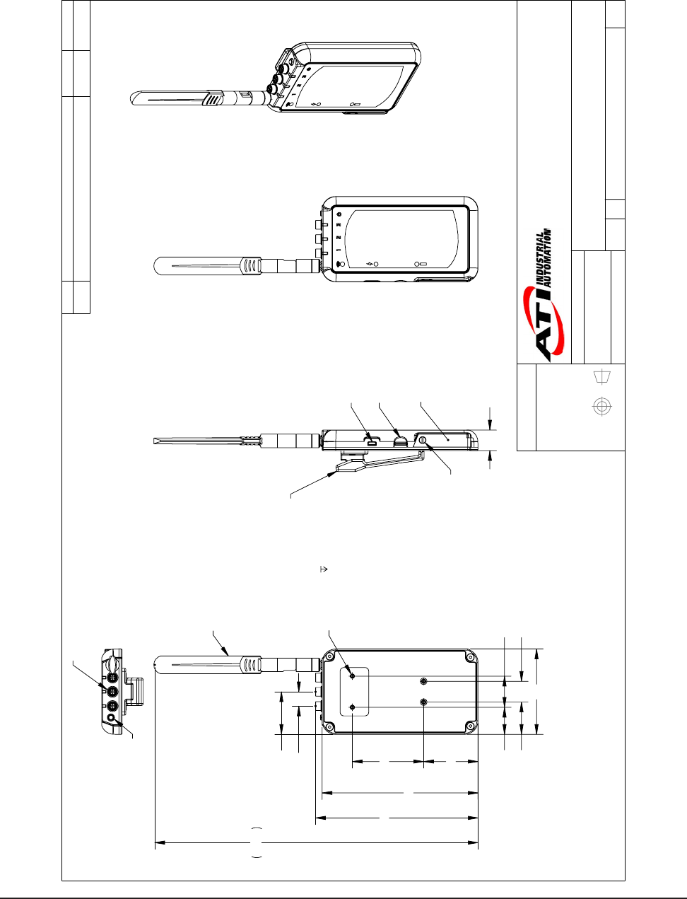
Wireless F/T Installation and Operation Manual
Document #9620-05-Wireless FT-03
Pinnacle Park • 1031 Goodworth Drive • Apex, NC 27539 USA • Tel: +1.919.772.0115 • Fax: +1.919.772.8259 • www.ati-ia.com • Email: info@ati-ia.com
50
11. Drawings
11.1 Wireless Net F/T for 3 Transducers
3rd ANGLE PROJECTION
82
150
4X M3X0.5
5
Customer Interface
2X 52.3
31 20
2X 68.6
26 30
310.9
13.7
Typ.
40.9
3X 156.3
Removable Antenna
19.7
MicroUSB Port
Battery Door
1/4-Turn
Door Latch
Optional Belt Clip
MicroSD Card Slot
Power button
3X Transducer Connector
Hirose
HR25-7TR-8SA(73)
Rev.
Description
Initiator
Date
03
Changed antenna. Updated dimensions. Changed to
MicroUSB port from MiniUSB port. Updated description.
LCS
3/13/2014
B
1:2
1 1
REVISION
NOTES: UNLESS OTHERWISE
SPECIFIED.
DO NOT SCALE DRAWING.
ALL DIMENSIONS ARE IN
MILLIMETERS.
DRAWN BY:
CHECKED BY:
L. Strahler 5/16/13
A. Strotzer 06/12/13
TITLE
SCALE
SIZE
DRAWING NUMBER
PROJECT #
SHEET OF
9230-05-1445
111020-1
03
PROPERTY OF ATI INDUSTRIAL AUTOMATION, INC. NOT TO BE REPRODUCED IN ANY
MANNER EXCEPT ON ORDER OR WITH PRIOR WRITTEN AUTHORIZATION OF ATI.
1031 Goodworth Drive, Apex, NC 27539, USA
Tel: +1.919.772.0115 Email: info@ati-ia.com
Fax: +1.919.772.8259 www.ati-ia.com
ISO 9001 Registered Company
Wireless Net F/T for 1-3 Transducers
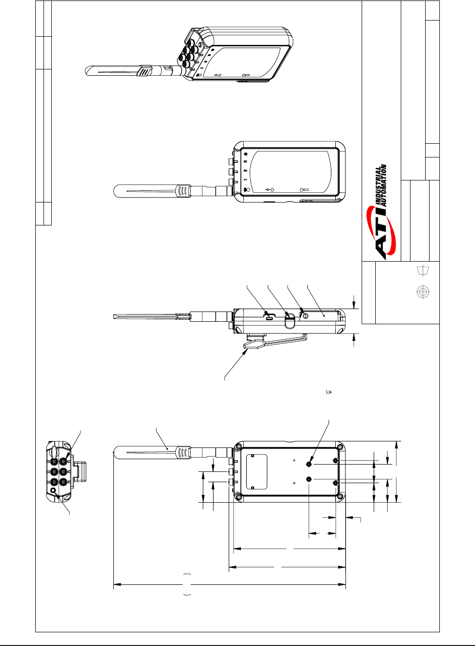
Wireless F/T Installation and Operation Manual
Document #9620-05-Wireless FT-03
Pinnacle Park • 1031 Goodworth Drive • Apex, NC 27539 USA • Tel: +1.919.772.0115 • Fax: +1.919.772.8259 • www.ati-ia.com • Email: info@ati-ia.com
51
11.2 Wireless Net F/T for 6 Transducers
3rd ANGLE PROJECTION
31 20
82
26 30
2X 13.1
2X 35.9
150
6X 156.3
310.9
2X 40.8
13.7 Typ
Removable Antenna
M3X0.5
5
Customer Interface
33
MicroUSB Port
Battery Door
1/4-Turn
Door Latch
Optional
Belt Clip
MicroSD
Card Slot
Power Button
6X Transducer Connector
Hirose
HR25-7TR-8SA(73)
Rev.
Description
Initiator
Date
02
Updated Description
RKC
7/14/2014
B
1:2
1 1
REVISION
NOTES: UNLESS OTHERWISE
SPECIFIED.
DO NOT SCALE DRAWING.
ALL DIMENSIONS ARE IN
MILLIMETERS.
DRAWN BY:
CHECKED BY:
R. Chambers 3/14/14
J. Walser 3/14/14
TITLE
SCALE
SIZE
DRAWING NUMBER
PROJECT #
SHEET OF
9230-05-1465
111020-1
02
PROPERTY OF ATI INDUSTRIAL AUTOMATION, INC. NOT TO BE REPRODUCED IN ANY
MANNER EXCEPT ON ORDER OR WITH PRIOR WRITTEN AUTHORIZATION OF ATI.
1031 Goodworth Drive, Apex, NC 27539, USA
Tel: +1.919.772.0115 Email: info@ati-ia.com
Fax: +1.919.772.8259 www.ati-ia.com
ISO 9001 Registered Company
Wireless Net F/T for 4-6 Transducers

Wireless F/T Installation and Operation Manual
Document #9620-05-Wireless FT-03
Pinnacle Park • 1031 Goodworth Drive • Apex, NC 27539 USA • Tel: +1.919.772.0115 • Fax: +1.919.772.8259 • www.ati-ia.com • Email: info@ati-ia.com
52
12. Terms and Conditions of Sale
The following Terms and Conditions are a supplement to and include a portion of ATI’s Standard Terms and
Conditions, which are on le at ATI and available upon request.
ATI warrants to Purchaser that force torque sensor products purchased hereunder will be free from defects in
material and workmanship under normal use for a period of one year from the date of shipment. This warranty
does not cover components subject to wear and tear under normal usage or those requiring periodic replacement.
ATI will have no liability under this warranty unless: (a) ATI is given written notice of the claimed defect and a
description thereof with thirty (30) days after Purchaser discovers the defect and in any event, not later than the last
day of the warranty period and (b) the defective item is received by ATI not later than (10) days after the last day
of the warranty period. ATI’s entire liability and Purchaser’s sole remedy under this warranty is limited to repair
or replacement, at ATI’s election, of the defective part or item or, at ATI’s election, refund of the price paid for the
item. The foregoing warranty does not apply to any defect or failure resulting from improper installation, operation,
maintenance, or repair by anyone other than ATI.
ATI will in no event be liable for incidental, consequential, or special damages of any kind, even if TI has been
advised of the possibility of such damages. ATI’s aggregate liability will in no event exceed the amount paid by the
purchaser for the item which is the subject of claim or dispute. ATI will have no liability of any kind for failure of
any equipment or other items not supplied by ATI.
No action against ATI, regardless of form, arising out of or in any way connected with products or services supplied
hereunder, may be brought more than one year after the cause of action accrued.
No representation or agreement varying or extending the warranty and limitation of remedy provisions contained
herein is authorized by ATI, and may not be relied upon as having been authorized by ATI, unless in writing and
signed by an executive ofcer of ATI.
Unless otherwise agreed in writing by ATI, all designs, drawings, data, inventions, software, and other technology
made or developed by ATI in the course of providing products and services hereunder, and all rights therein under
any patent, copyright, or other law protecting intellectual property, shall be and remain ATI’s property. The sale
of products or services hereunder does not convey any expressed or implied license under any patent, copyright,
or other intellectual property right owned or controlled by ATI, whether relating to the products sold or any other
matter, except for the license expressly granted below.
In the course of supplying products and services hereunder, ATI may provide or disclose to Purchaser condential
and proprietary information of ATI relating to the design, operation, or other aspects of ATI’s products. As between
ATI and Purchaser, ownership of such information, including without limitation any computer software provided
to Purchaser by ATI, shall remain in ATI and such information is licensed to Purchaser only for Purchaser’s use in
operating the products supplied by ATI hereunder in Purchaser’s internal business operations.
Without ATI’s prior written permission, Purchaser will not use such information for any other purpose of provide or
otherwise make such information available to any third party. Purchaser agrees to take all reasonable precautions to
prevent any unauthorized use or disclosure of such information.
Purchaser will not be liable hereunder with respect to disclosure or use of information which: (a) is in the public
domain when received from ATI, (b) is thereafter published or otherwise enters the public domain through no fault
of Purchaser, (c) is in Purchaser’s possession prior to receipt from ATI, (d) is lawfully obtained by Purchaser from a
third party entitled to disclose it, or (f) is required to be disclosed by judicial order or other governmental authority,
provided that, with respect to such to maintain the condentiality of such information.

Wireless F/T Installation and Operation Manual
Document #9620-05-Wireless FT-03
Pinnacle Park • 1031 Goodworth Drive • Apex, NC 27539 USA • Tel: +1.919.772.0115 • Fax: +1.919.772.8259 • www.ati-ia.com • Email: info@ati-ia.com
53
Appendix A – UDP Command CRC Calculation
All UDP commands sent to the Wireless F/T must include a two-byte CRC (Cyclic Redundancy Check) value. This value
is used for error checking the command request and is based on the data in the command structure to be sent.
The following C code performs the calculation of the CRC value. To calculate the value, pass a pointer to the command
structure along with the command length in bytes minus two to the function crcBuf().
// If FAST is dened, then the CRC is determined using a lookup table instead of
calculations
#dene FAST 1
// Both versions use the CRC-16-CCITT polynomial: x^16 + x^12 + x^5 + 1 = 0x11021
#if FAST
unsigned short crcByte(unsigned short crc, unsigned char ch) // lookup table version
(bigger & faster)
{
static const unsigned short ccitt_crc16_table[256] =
{
0x0000, 0x1021, 0x2042, 0x3063, 0x4084, 0x50a5, 0x60c6, 0x70e7,
0x8108, 0x9129, 0xa14a, 0xb16b, 0xc18c, 0xd1ad, 0xe1ce, 0xf1ef,
0x1231, 0x0210, 0x3273, 0x2252, 0x52b5, 0x4294, 0x72f7, 0x62d6,
0x9339, 0x8318, 0xb37b, 0xa35a, 0xd3bd, 0xc39c, 0xf3ff, 0xe3de,
0x2462, 0x3443, 0x0420, 0x1401, 0x64e6, 0x74c7, 0x44a4, 0x5485,
0xa56a, 0xb54b, 0x8528, 0x9509, 0xe5ee, 0xf5cf, 0xc5ac, 0xd58d,
0x3653, 0x2672, 0x1611, 0x0630, 0x76d7, 0x66f6, 0x5695, 0x46b4,
0xb75b, 0xa77a, 0x9719, 0x8738, 0xf7df, 0xe7fe, 0xd79d, 0xc7bc,
0x48c4, 0x58e5, 0x6886, 0x78a7, 0x0840, 0x1861, 0x2802, 0x3823,
0xc9cc, 0xd9ed, 0xe98e, 0xf9af, 0x8948, 0x9969, 0xa90a, 0xb92b,
0x5af5, 0x4ad4, 0x7ab7, 0x6a96, 0x1a71, 0x0a50, 0x3a33, 0x2a12,
0xdbfd, 0xcbdc, 0xfbbf, 0xeb9e, 0x9b79, 0x8b58, 0xbb3b, 0xab1a,
0x6ca6, 0x7c87, 0x4ce4, 0x5cc5, 0x2c22, 0x3c03, 0x0c60, 0x1c41,
0xedae, 0xfd8f, 0xcdec, 0xddcd, 0xad2a, 0xbd0b, 0x8d68, 0x9d49,
0x7e97, 0x6eb6, 0x5ed5, 0x4ef4, 0x3e13, 0x2e32, 0x1e51, 0x0e70,
0xff9f, 0xefbe, 0xdfdd, 0xcffc, 0xbf1b, 0xaf3a, 0x9f59, 0x8f78,
0x9188, 0x81a9, 0xb1ca, 0xa1eb, 0xd10c, 0xc12d, 0xf14e, 0xe16f,
0x1080, 0x00a1, 0x30c2, 0x20e3, 0x5004, 0x4025, 0x7046, 0x6067,
0x83b9, 0x9398, 0xa3fb, 0xb3da, 0xc33d, 0xd31c, 0xe37f, 0xf35e,
0x02b1, 0x1290, 0x22f3, 0x32d2, 0x4235, 0x5214, 0x6277, 0x7256,
0xb5ea, 0xa5cb, 0x95a8, 0x8589, 0xf56e, 0xe54f, 0xd52c, 0xc50d,
0x34e2, 0x24c3, 0x14a0, 0x0481, 0x7466, 0x6447, 0x5424, 0x4405,
0xa7db, 0xb7fa, 0x8799, 0x97b8, 0xe75f, 0xf77e, 0xc71d, 0xd73c,
0x26d3, 0x36f2, 0x0691, 0x16b0, 0x6657, 0x7676, 0x4615, 0x5634,
0xd94c, 0xc96d, 0xf90e, 0xe92f, 0x99c8, 0x89e9, 0xb98a, 0xa9ab,
0x5844, 0x4865, 0x7806, 0x6827, 0x18c0, 0x08e1, 0x3882, 0x28a3,
0xcb7d, 0xdb5c, 0xeb3f, 0xfb1e, 0x8bf9, 0x9bd8, 0xabbb, 0xbb9a,
0x4a75, 0x5a54, 0x6a37, 0x7a16, 0x0af1, 0x1ad0, 0x2ab3, 0x3a92,
0xfd2e, 0xed0f, 0xdd6c, 0xcd4d, 0xbdaa, 0xad8b, 0x9de8, 0x8dc9,
0x7c26, 0x6c07, 0x5c64, 0x4c45, 0x3ca2, 0x2c83, 0x1ce0, 0x0cc1,
0xef1f, 0xff3e, 0xcf5d, 0xdf7c, 0xaf9b, 0xbfba, 0x8fd9, 0x9ff8,
0x6e17, 0x7e36, 0x4e55, 0x5e74, 0x2e93, 0x3eb2, 0x0ed1, 0x1ef0
};
return ccitt_crc16_table[((crc >> 8) ^ ch) & 0xff] ^ (crc << 8);
}

Wireless F/T Installation and Operation Manual
Document #9620-05-Wireless FT-03
Pinnacle Park • 1031 Goodworth Drive • Apex, NC 27539 USA • Tel: +1.919.772.0115 • Fax: +1.919.772.8259 • www.ati-ia.com • Email: info@ati-ia.com
54
#else
unsigned short crcByte(unsigned short crc, unsigned char ch) // direct calculation
version (smaller & slower)
{
unsigned short crc_new = (unsigned char)(crc >> 8) | (crc << 8);
crc_new ^= ch;
crc_new ^= (unsigned char)(crc_new & 0xff) >> 4;
crc_new ^= crc_new << 12;
crc_new ^= (crc_new & 0xff) << 5;
return crc_new;
}
#endif
#dene CRC_INIT 0x1234 // this is the seed value used for along with the buffer’s
rst byte
unsigned short crcBuf(const void * buff, unsigned long len)
{
unsigned long i;
unsigned short crc = CRC_INIT;
const char * buf = buff;
for(i = 0; i < len; i++)
{
crc = crcByte(crc, buf[i]);
}
return crc;
}
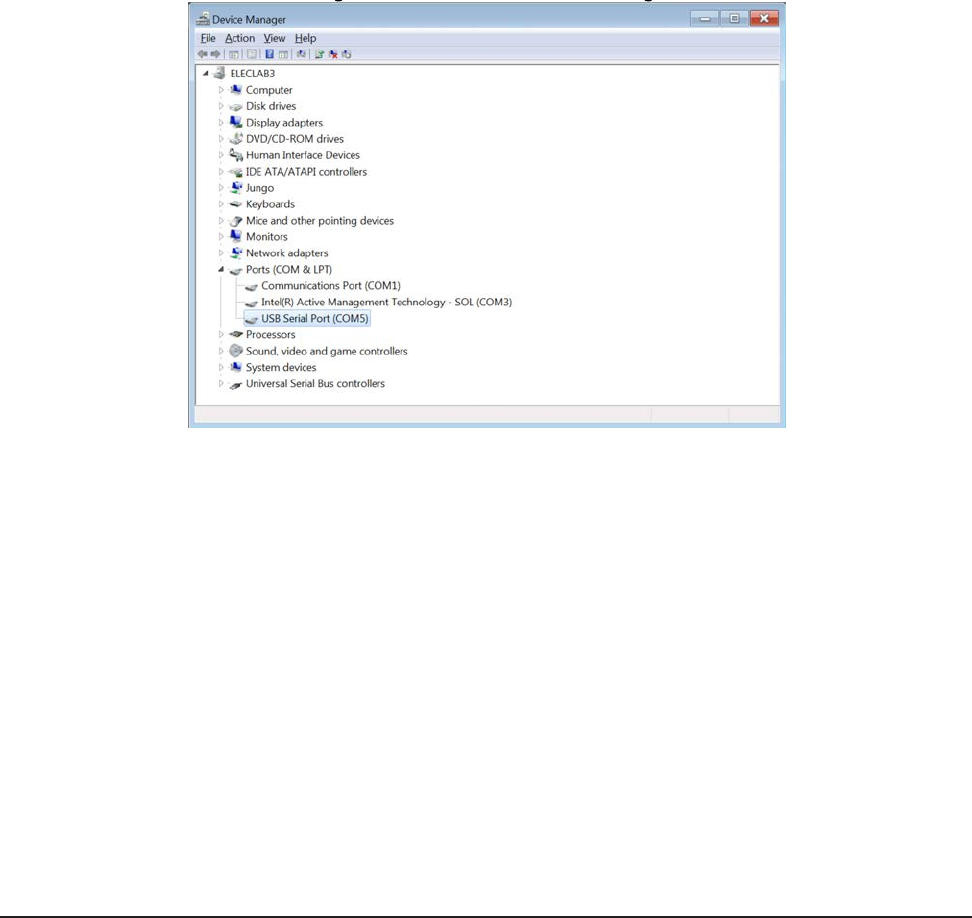
Wireless F/T Installation and Operation Manual
Document #9620-05-Wireless FT-03
Pinnacle Park • 1031 Goodworth Drive • Apex, NC 27539 USA • Tel: +1.919.772.0115 • Fax: +1.919.772.8259 • www.ati-ia.com • Email: info@ati-ia.com
55
Appendix B–InitialCongurationUsingaTelnetProgam(PuTTY)
B.1 InitialCongurationUsing
The Wireless F/T must be congured before communicating with the device. The following procedure will
help provide steps to congure the Wireless F/T.
1. Install Virtual Communication Port Driver from the following website: http://www.ftdichip.com/
Support/Documents/InstallGuides.htm
Select the instructions for the operating system running on the computer being used to congure the
wireless F/T system. Follow the instructions to load the device driver on the computer.
2. Find the serial port number used by the Wireless unit by opening Device Manager (you can get to it by
typing “Device Manager” in the Windows 7® Start Menu search bar), expanding the “Ports (COM &
LPT)” section, and nding a connection labeled “USB Serial Port (COMx)” If there’s more than one
serial port, you may have to disconnect the USB cable and see which COM port is removed in the device
manager, then reconnect the USB cable. The example in Figure 5.2 shows Wireless F/T is connected to
COM5.
Figure11.1—Windows 7® DeviceManager
3. Install a telnet terminal program like PuTTY. Visit http://putty.org to download the executable le (putty.
exe) for the PuTTY program.
4. Open (PuTTY) terminal program by clicking on the (putty) icon and selecting Run from the pop up
window.
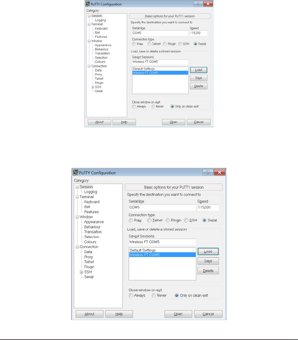
Wireless F/T Installation and Operation Manual
Document #9620-05-Wireless FT-03
Pinnacle Park • 1031 Goodworth Drive • Apex, NC 27539 USA • Tel: +1.919.772.0115 • Fax: +1.919.772.8259 • www.ati-ia.com • Email: info@ati-ia.com
56
5. In the Category pane click on Connection > Serial and ll in the following elds:
• Serial line to connect to COM5 (Enter the Com port the Wireless unit is using)
• Speed (baud) 115200
• Data bits 8
• Stop bits 1
• Parity None
• Flow control None
Figure11.2—PuTTyTerminalProgram
6. In the Category pane click on Session, The Serial Line should now be the COM port and Speed should
be the values entered in the previous step. In the Saved Sessions eld enter Wireless FT COM5 and
select save. This will allow you to use this conguration at another time.
Figure11.3—PuTTYConguration
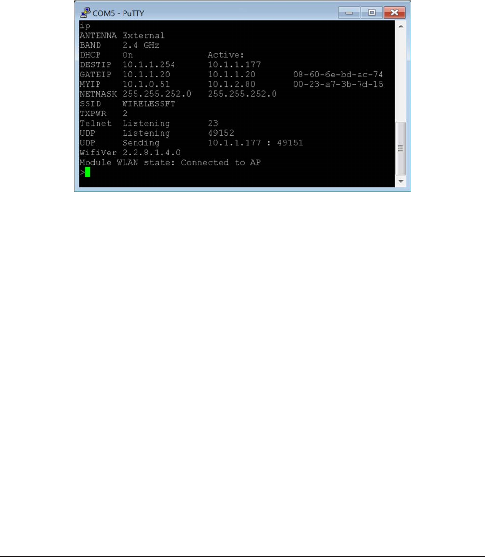
Wireless F/T Installation and Operation Manual
Document #9620-05-Wireless FT-03
Pinnacle Park • 1031 Goodworth Drive • Apex, NC 27539 USA • Tel: +1.919.772.0115 • Fax: +1.919.772.8259 • www.ati-ia.com • Email: info@ati-ia.com
57
7. Connect to the console, e.g. by pressing “Open” in PuTTy. Information will appear as the unit attempts
to connect to a wireless network.
8. In the COMx – PuTTY Window type “d” and press Enter key.
9. In the COMx – PuTTY Window type “t” and press Enter key. (Turns off the wireless connection on the
unit).
10. Test that the unit is working by entering “IP” followed by the Enter key. This is the IP command, and
will present the current IP settings. Refer to the following example screen.
Figure11.4—TesttheConnection
11. Obtain the following information from your network administrator: IP Address to use for the unit, Subnet
Mask, Default Gateway, SSID, whether the Wi-Fi network operates on 2.4 or 5 gigahertz spectrum, IP
address of the computer you’re using to communicate with the unit.
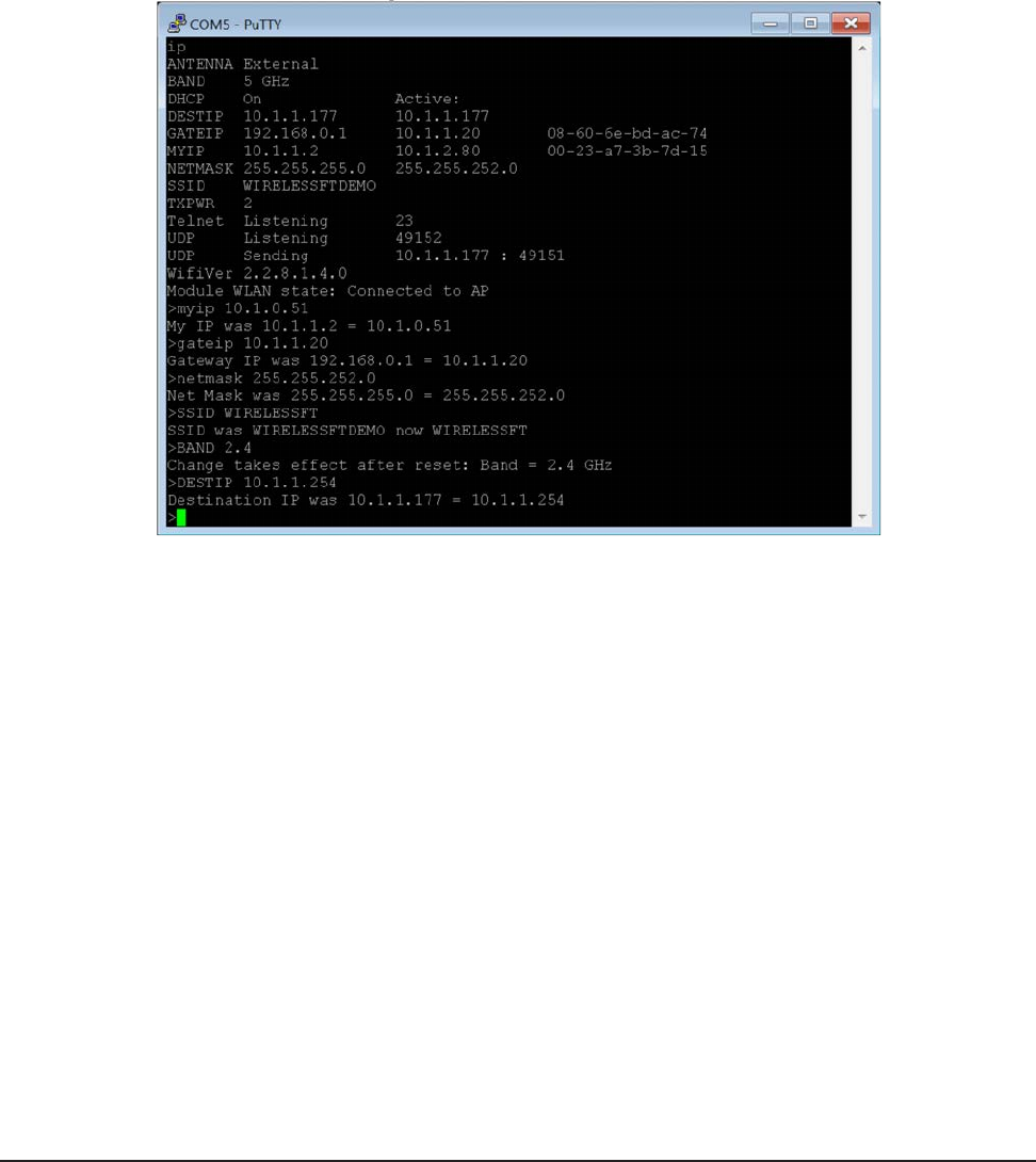
Wireless F/T Installation and Operation Manual
Document #9620-05-Wireless FT-03
Pinnacle Park • 1031 Goodworth Drive • Apex, NC 27539 USA • Tel: +1.919.772.0115 • Fax: +1.919.772.8259 • www.ati-ia.com • Email: info@ati-ia.com
58
12. Enter these commands in any order: (Commands are not case sensitive except where indicated)
c. “MYIP <unitip>”, e.g. “MYIP 192.168.1.50”
d. “NETMASK <subnetmask>”
e. “GATEIP <defaultgateway>”
f. “SSID <ssid>” Network<ssid> (Is case sensitive)
g. “BAND <x>” where x is “2.4” for 2.4 gigahertz or “5” for 5 gigahertz.
h. “DESTIP <yourcomputersip>”
Figure11.5—TesttheConnection
13. Enter the “SAVEALL” command followed by the “RESET” command for the new settings to take effect.
14. Close the terminal program.
15. Press the On/Off switch for two seconds to power down. Then press again to power up. After
initialization the unit will connect to the wireless network and begin streaming data.
16. Disconnect the USB cable from the Wireless F/T unit and the computer.