ATID RM100USA UHF RFID READER User Manual Microsoft PowerPoint RM 100USA User s manual
ATID Co., Ltd UHF RFID READER Microsoft PowerPoint RM 100USA User s manual
ATID >
USERS MANUAL
RM-100 USA User’s Manual
Key Features
•ISO 18000-6C(Gen2) protocol support
•Dynamic RF output power : -4dBm to +27dBm
•Low current to extend battery life
•Compact size
•Low cost
UHF RFID READER MODULE
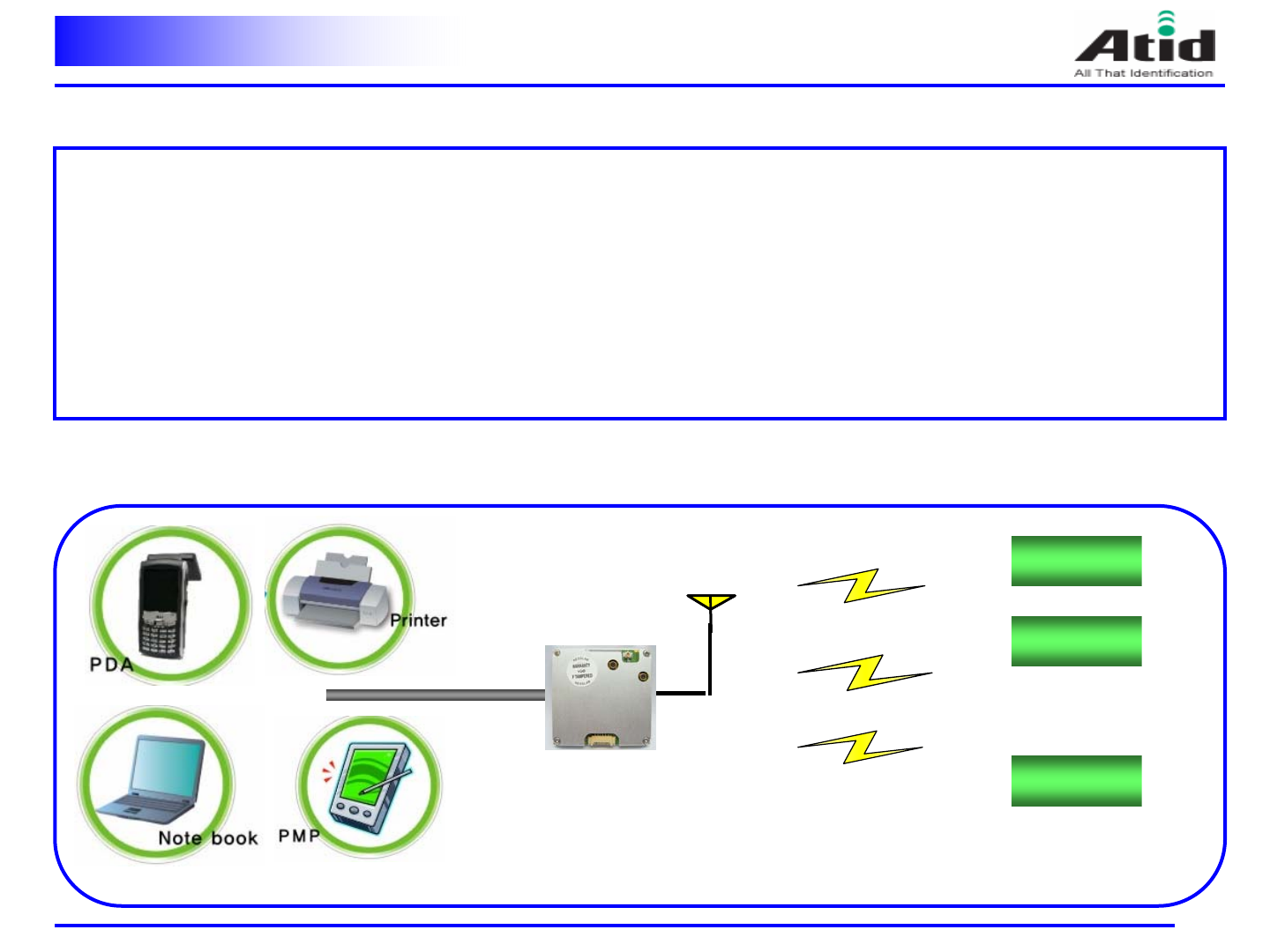
Introduction and system composition diagram
2
•The RM-100EUROPE is an compact size RFID reader module developed for the embedded reader market,
which comprises printers, industrial PDA , and similar devices.
•Target Application
- PDA type RFID Reader
-RFID PRINTER
- OEM Module
- Other application
◈Introduction ◈
◈System composition diagram ◈
UART
Tag #1
Tag #2
Tag #N
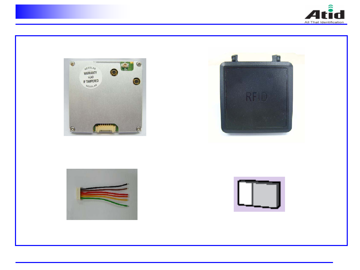
Composition parts
Reader module Antenna
User manual
3
Interface connector cable
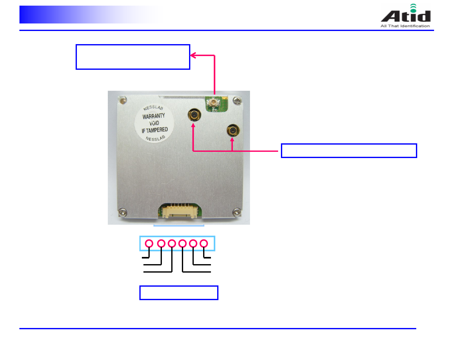
Module Description
4
ANT port : connect rf cable to
reader module and ANT.
VCC : 4.0 V 1A
USB_D-
TXD
RXD
VCC
GND
USB_D+
RF switch connector : TX, RX test port.
5
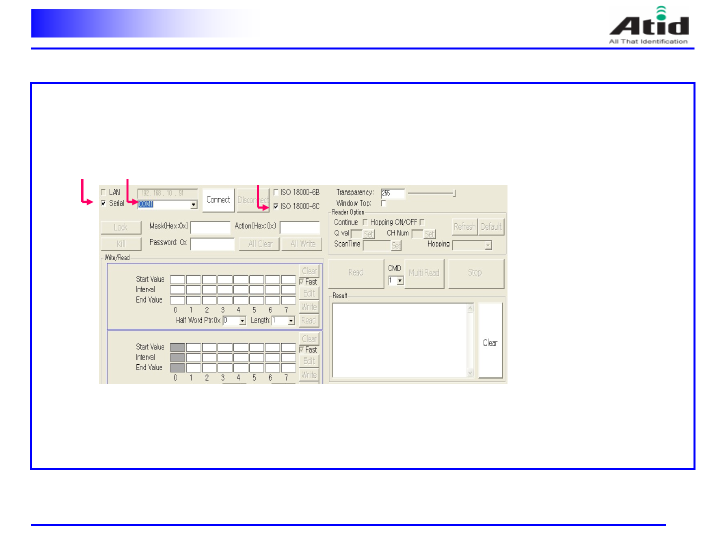
◈Nesslab RFID Mobile Reader Application v1.0 setting
- Program Setting
1. Connect serial data cable (RS-232 to UART) to PC and Reader.
2. Run “Nesslab RFID Mobile Reader Application v1.0 ”with window XP
3. First, check “Serial , ISO 1800-6C and COM1 “.
4. Supply 4.0v to module. The buzzer is sounded “BEEP “
Operation method ----------(1)
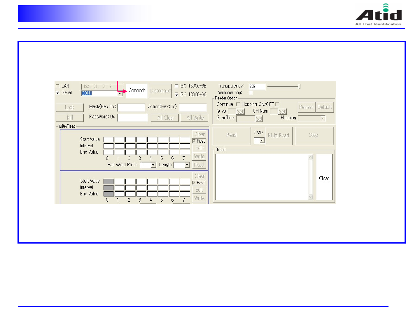
Operation method ----------(2)
6
4. Click “connect “.
Operation method ----------(3)
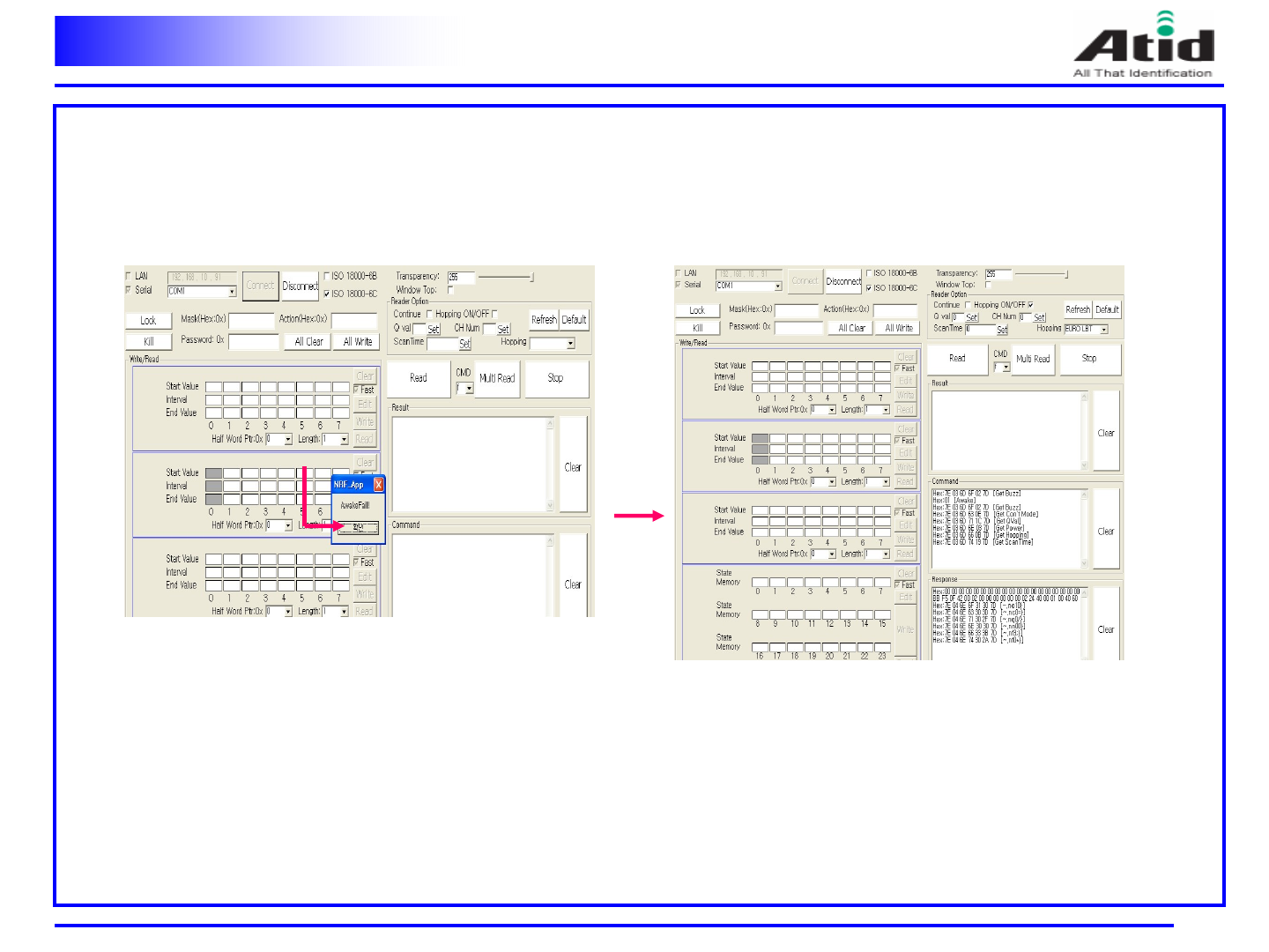
6
5. Cleck “확인 “6. If this screen is displaied“, the program setting is complited
Operation method ----------(4)
6
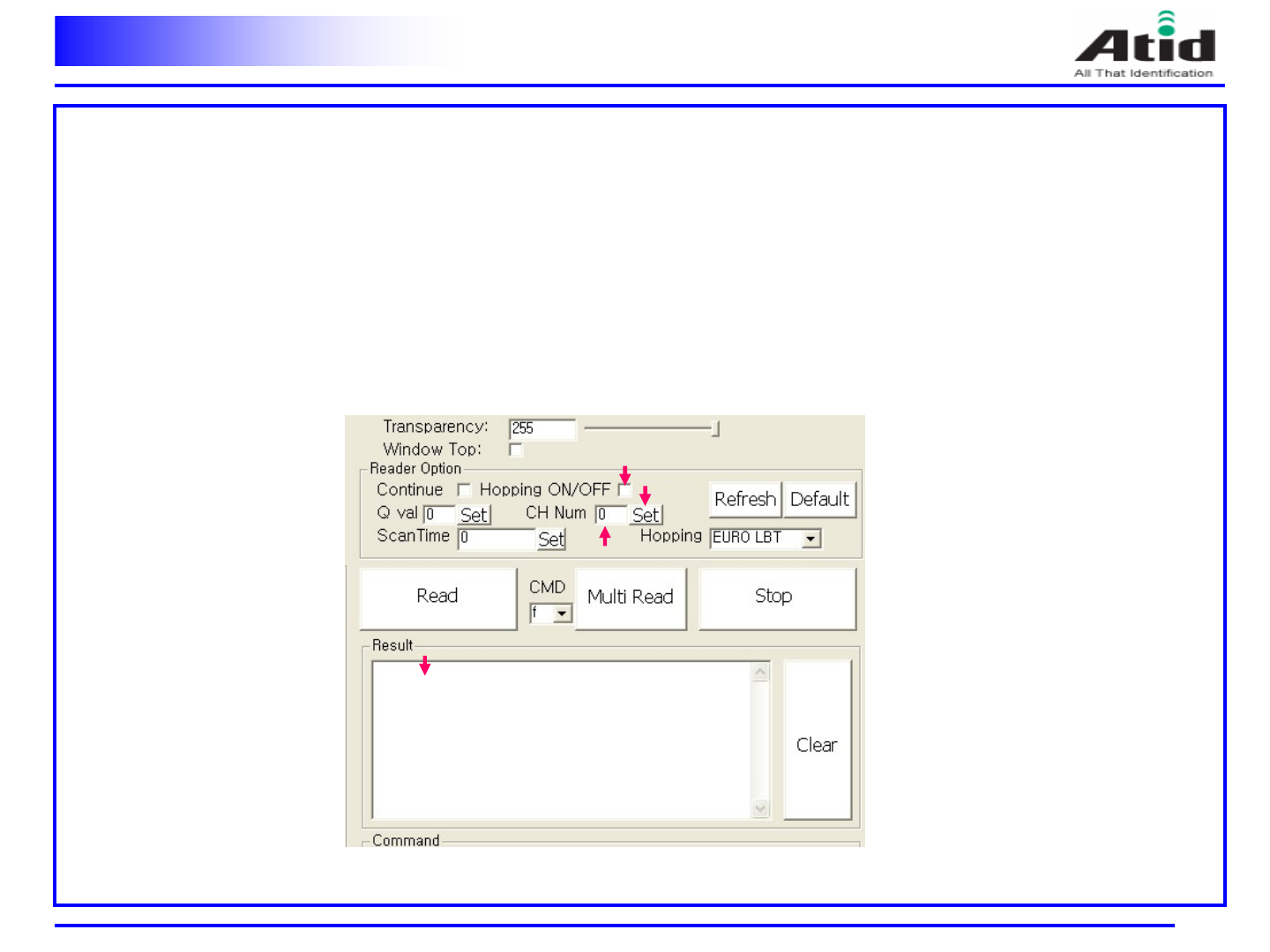
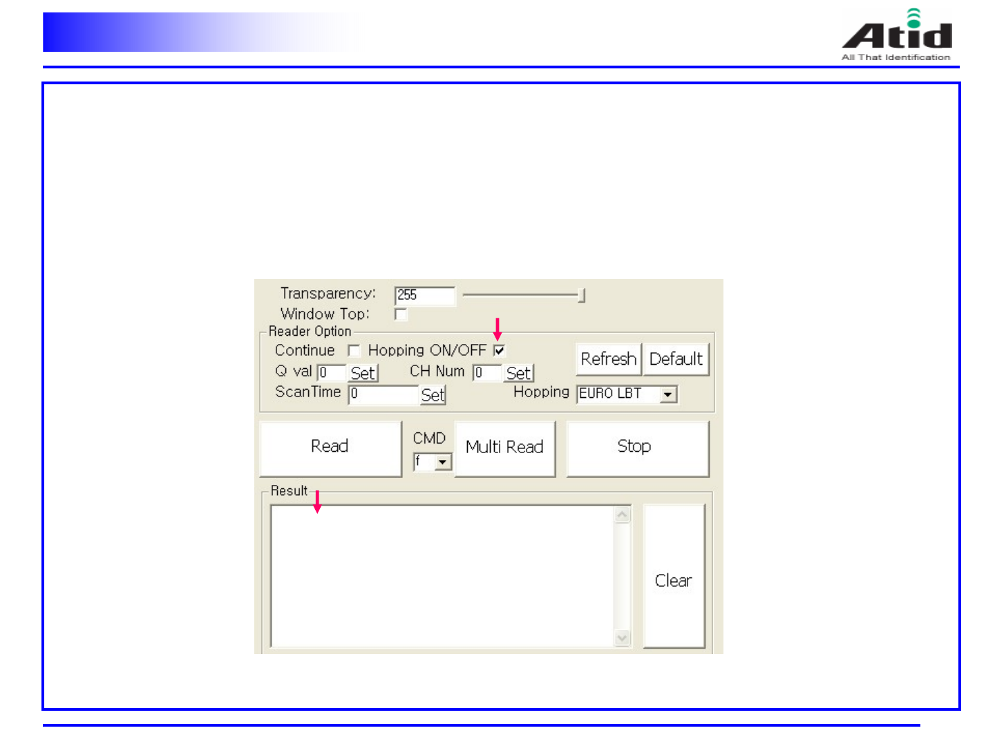
-Program Setting
1. The channel setting operation
1) If the frequency hopping ON/OFF check box is checked, set the frequency hopping ON/OFF check box unchecked.
2) Write the channel number to the CH NUM box.
3) Click “SET “, then the channel setting is completed
4) If you click “Multi Read “the module read the tags at the channel which you check.
5) The tag data is displayed at the Result box.
Operation method ----------(4)
6
2. The normal operation
1) If the frequency hopping ON/OFF check box is unchecked, set the frequency hopping ON/OFF check box checked.
2) If you click “Multi Read “, the module read the tags.
3) The tag data is displayed at the Result box.
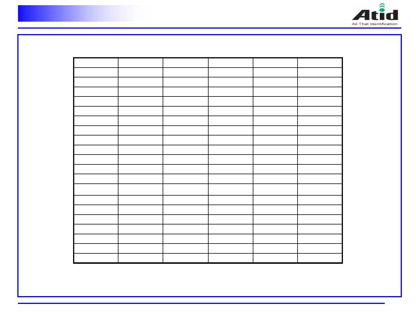
Channel Table
6
918.0 MHz40914.0 MHz20
917.8 MHz39913.8MHz19
917.6MHz38913.6MHz18
917.4 MHz37913.4 MHz17
917.2 MHz36913.2 MHz16
917.0 MHz35913.0 MHz15
916.8 MHz34912.8 MHz14
916.6 MHz33912.6 MHz13
916.4 MHz32912.4 MHz12
916.2 MHz31912.2 MHz11
920.0 MHz50916.0 MHz30912.0MHz10
919.8 MHz49915.8 MHz29911.8 MHz9
919.6 MHz48915.6 MHz28911.6 MHz8
919.4 MHz47915.4 MHz27911.4 MHz7
919.2 MHz46915.2 MHz26911.2 MHz6
919.0 MHz45915.0 MHz25911.0 MHz5
918.8 MHz44914.8 MHz24910.8 MHz4
918.6 MHz43914.6 MHz23910.6 MHz3
918.4 MHz42914.4 MHz22910.4 MHz2
918.2 MHz41914.2 MHz21910.2 MHz1
FREQUENCY
CHANNEL NOFREQUENCYCHANNEL NOFREQUENCYCHANNEL NO
- Additional Page -
Cautions
Modifications not expressly approved by the party responsible for compliance could void
the user’s authority to operate the equipment.
FCC compliance Information
This device complies with part 15 of FCC Rules.
Operation is subject to the following two conditions: 1. This device may not cause
harmful interference, and 2. This device must accept any interference received.
Including interference that may cause undesired operation.
Information to User
This equipment has been tested and found to comply with the limits for a Class B
digital device, Pursuant to part 15 of the FCC Rules. These limits are designed to
provide reasonable protection against harmful interference in a residential installation.
This equipment generates, uses and can radiate radio Frequency energy and, if not
installed and used in accordance with the instructions, may cause harmful interference
to radio communications.
However, there is no guarantee that interference will not occur in a particular installation.
If this equipment does cause harmful interference to radio or television reception, which
can be determined by turning the equipment off and on, the user is encouraged to try
to correct the interference by one or more of the following measures:
- Reorient or relocate the receiving antenna.
- Increase the separation between the equipment and receiver
- Connect the equipment into an outlet on a circuit different from that to which the
receiver is connected.
- Consult the dealer or an experienced radio/TV technician for help.
FCC WARNING:
This equipment may generate or use radio frequency energy. Changes or modifications
to this equipment may cause harmful interference unless the modifications are expressly
approved in the instruction manual. The user could lose the authority to operate this
equipment if an unauthorized change or modification is made.
FCC RF EXPOSURE:
The EUT will only be used with a separation of 20 centimeters or greater between the antenna and the
body of the user.