ATOP Technologies SE5901B-AF Industrial Cellular Serial Device Server, Industrial Cellular Modbus Gateway, Industrial Cellular Modbus Concentrator, Industrial Cellular Protocol Gateway User Manual SE MB PG 5901B 2018 12 10
ATOP Technologies, INC. Industrial Cellular Serial Device Server, Industrial Cellular Modbus Gateway, Industrial Cellular Modbus Concentrator, Industrial Cellular Protocol Gateway SE MB PG 5901B 2018 12 10
User Manual
Industrial Cellular Serial Device Server
Industrial Cellular Modbus Gateway
Industrial Cellular Modbus Concentrator
Industrial Cellular Protocol Gateway
SE5901B/MB5901B/PG5901B Series
89900500G
Updated in December, 2018
Version V1.2
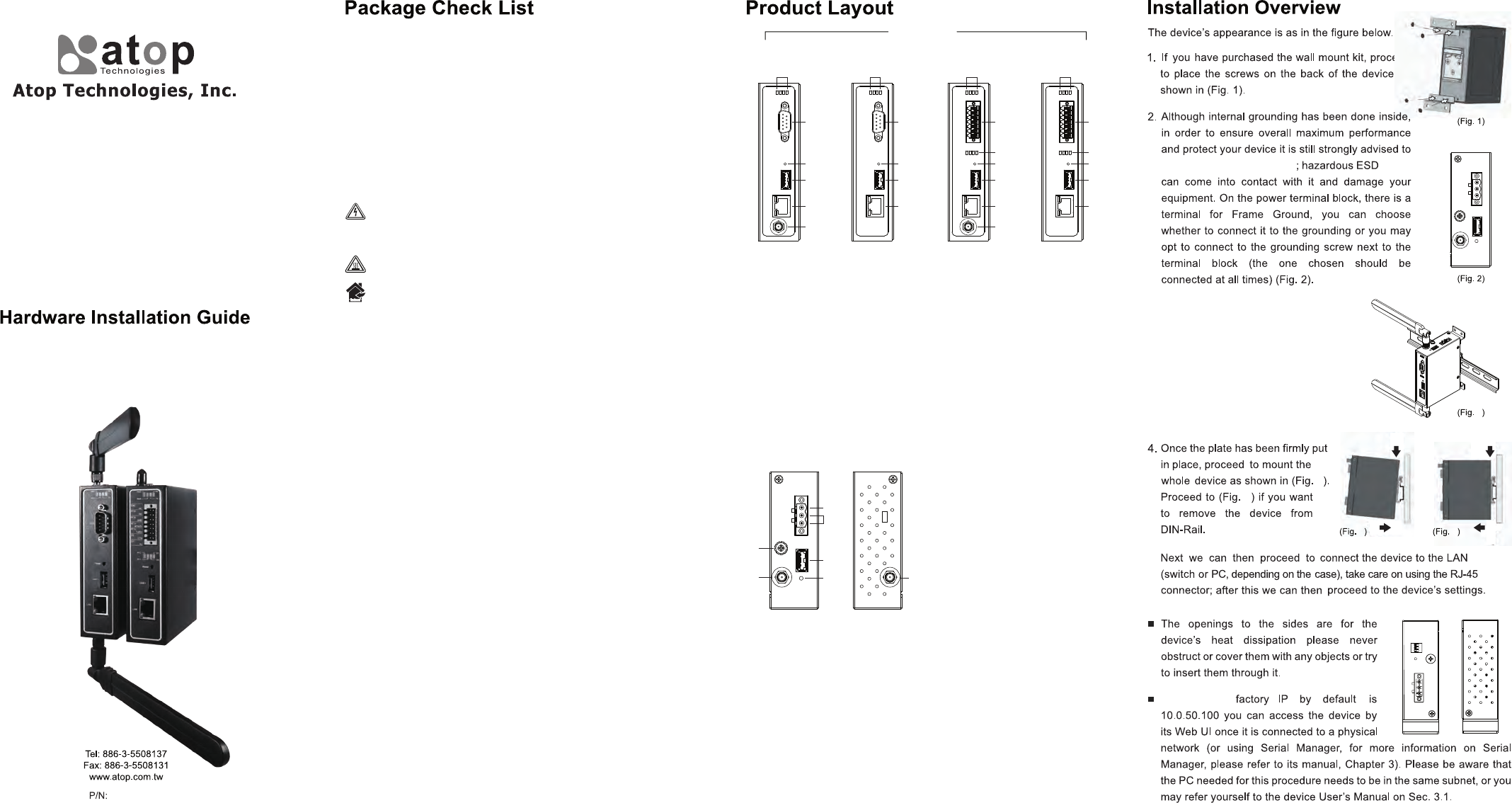
Inside the package you will find the following items:
Industrial 3G/4G Serial Gateway x 1 or
Industrial 3G/4G Modbus Gateway x 1 or
Industrial 3G/4G Modbus Concentrator x 1 or
Industrial 3G/4G Protocol Gateway x 1
3-Pin 5.08mm Lockable Terminal Block
(Already mounted to the device) x 1
2x7 Pin 3.5mm Lockable Terminal Block (IO version only) x 1
DIN-Rail Kit (Already mounted to the device) x 1
Installation Guide with Warranty Card x 1
This device complies with part 15 of the FCC Rules.
Operation is subject to the following two conditions:
(1) This device may not cause harmful interference, and
(2) This device must accept any interference received, including
interference that maycause undesired operation.
Notice:
Any changes or modifications not expressly approved by the party responsible
for compliance could void your authority to operate the equipment.
NOTE:
This equipment has been tested and found to comply with the limits for a
Class B digitaldevice, pursuant to part 15 of the FCC Rules.
These limits are designed to provide reasonable protection against harmful
interference in a residential installation.
This equipment generates, uses and can radiate radio frequency energy and,
if not nstalled and used in accordance with the instructions, may cause
harmful interference to radio communications.
However, there is no guarantee that interference will not occur in a particular
installation. If this equipment does cause harmful interference to radio or
television reception, which can be determined by turning the equipment off
and on, the user is encouraged to try to correct the interference by one or
more of the following measures:
- Reorient or relocate the receiving antenna.
- Increase the separation between the equipment and receiver.
- Connect the equipment into an outlet on a circuit different from that to
which the receiver is connected.
- Consult the dealer or an experienced radio/ TV technician for help.
The antenna(s) used for this transmitter must not be co-located of operating in
conjunction with any other antenna or transmitter.
This device complies with FCC radiation exposure limits set forth for an
uncontrolled environment. Ln order to avoid the possibility of exceeding the
Fcc radio frequency exposure limits, human proximity to the antenna shall not
be less than 20cm (8inches) during normal operation.
Never install or work on electrical or cabling during periods of
lightning activity.
Never connect or disconnect power when hazardous gases
are present.
Warning:Hot Surface Do Not Touch.
IndoorIndoor
This equipment should be installed indoor and not connect directly
with equipment installed outdoor.
TOP View Bottom View
7
1
2
3
4
5
6
1. Grounding Screw
2. SMA Connector for Antenna
(4G version only)
3. Frame Ground
4. Terminal for Power
5. USB2
6. PWR Reset
7. SMA Connector for Antenna
(4G version only)
Front View
3G DB9 Type
1~4
5
11
12
13
14
4G DB9 Type
1~4
5
11
12
13
4G IO Type
1~4
6
7~10
11
12
13
3G IO Type
1~4
6
7~10
11
12
13
14
1. PWR LED
2. RUN LED
3. COM1 Tx LED
4. COM1 Rx LED
5. 9-Pin Male D-Sub Connector
for RS-232/485
6. 14-Pin 3.5 mm Terminal Block
for RS-232/485(COM1),
RS-232(COM2), Relay, and DI
7. Relay2 LED
8. Relay1 LED
9. DI2 LED
10. DI1 LED
11. Default Button
12. PWR USB
13. 10/100/1000 BASE-T(X) Ports
14. SMA Connector for Antenna
(D3G version only)
The device's
ground the device properly
1
2
4
5.
3. Proceed then to fix the antennas to the
female RP-SMA connectors deemed to
(Fig. 3). You can then choose whether
to plug in the I/O ports at this point or do
it later depending on the actual location
of the device or level of comfort for
performing such operation. 3
4
5
2
1
5
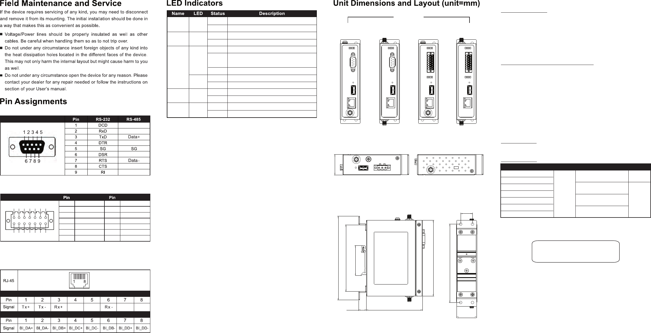
Pin Assignments and Connections
10/100/1000BASE-T(X) Ethernet Pinout
10/100Base-T(X)
1000Base-T(X)
9-Pin Male D-Sub Connector for RS-232/485
2 x 7-pin Male Terminal Block for RS-232/485(COM 1),
RS-232(COM 2) Relay and DI
–
–
–
–
–
–
Relay Output with current carrying capacity of 1A@30 VDC (Normal open)
Rx1
CTS
8
9
10 Tx1/D+
11
12
13
14
1
2
3
4
5
6
7
RTS/D-
SG
Rx2
Tx2
Assignment
DI1
DI2
RY1c
RY1+
RY2c
RY2+
SG
Assignment
1 2 3 4 5 6 7
8 9 10 11 12 13 14
COM-TX
COM-RX
Blinking
Off
Blinking
Off
Green
Green
COM port is transmitting data
COM port is not transmitting data
COM port is receiving data
COM port is not receiving data
Orange
(Speed)
LAN
Power Green
On
On
Off
Off
Off
Blinking
slowly Ethernet is transmitting at 100Mbps
Blinking
On/Off
Blinking
Ethernet is transmitting at 1Gbps
Power is being supplied
Ethernet is transmitting at 10Mbps
Ethernet no data transmit
Power is not supplied
Ethernet data is transmitting
System is not ready or halt
AP Firmware is running normally
Green
Green
(Data)
RUN
Rear View
Side View
Bottom ViewTop View
SE/MB/PG5901B
-D3G
SE/MB/PG5901B
-4G
SE/MB/PG5901B
-IO-D3G
SE/MB/PG5901B
-IO-4G
Front View
32
18,5
122,6
31,5
121,5
48,3
90
12,5
107
134,6
Customers shall always obtain an authorized "RMA" number from Atop before
shipping the goods to be repaired to Atop. When in normal use, a sold product
shall be replaced with a new one within 3 months after purchase. The shipping
cost from the customer to Atop will be reimbursed by Atop.
After 3 months and still within the warranty period, it is up to Atop whether to
replace the unit with a new one; normally, as long as a product is under warranty,
all parts and labor are free of charge to the customers.
After the warranty period, the customer shall cover the cost for parts and
labor.Three months after purchase, the shipping cost from the customer to Atop
will not be reimbursed, but the shipping cost from Atop to the customer will be
paid by Atop.
Atop shall not be held responsible for any consequential losses from using Atop’s
product.
Warranty Policy
The warranty certification will not be effective until an authorized stamp issued by
Atop’s overseas agents.
Purchase Date: / / (yyyy/mm/dd)
Serial Number
Product CategoriesWarranty WarrantyProduct Categories
Media Converters
Embedded Device Servers
Ethernet Switches
Wireless
Serial Device Servers
Modbus Gateways 5 Years
Protocol Gateways
DIN-Rail Power Supplies 3 years
1 years
Power Adaptors
Antennas
Other Accessories
Warranty Conditions
RMA and Shipping Costs Reimbursement
1. Please contact your local dealers or Atop Technical Support Center at the
following numbers.
+ 886-3-550-8137 (Atop Taiwan)
+ 86-21-6495-6232 (Atop China)
2. Please report the defected problems via Atop’s Web site or E-mail account
Web Site:www.atop.com.tw, e-mail:service@atop.com.tw
Web Site:www.atop.com.cn, e-mail:service@atop.com.cn
3. Company Addr: 2F, No. 146, Sec. 1, Tung-Hsing Rd., Jubei, Hsinchu 30261,
Taiwan, R.O.C.
Manufacturer Addr: 1st FL 30 R&D RD II,SCIENCE-BASED INDUSTRIAL
PARK,HSINCHU 300 TAIWAN, R.O.C
Atop Customer Services and Supports
Limited Liability
Products supplied by Atop Technologies are covered in this warranty for
sub-standard performance or defective workmanship. The warranty is not,
however, extended to goods damaged in the following circumstances:
(a) Excessive forces or impacts
(b) War or an Act of God: wind storm, fire, flood, electric shock, earthquake
(c) Use of unqualified power supply, connectors, or unauthorized parts/kits
(d) Replacement with unauthorized parts
Warranty Period
─ Any changes to this material will be announced on Atop website. ─