ATOP Technologies SW5001-WGN1 Wireless Serial Server User Manual Manual
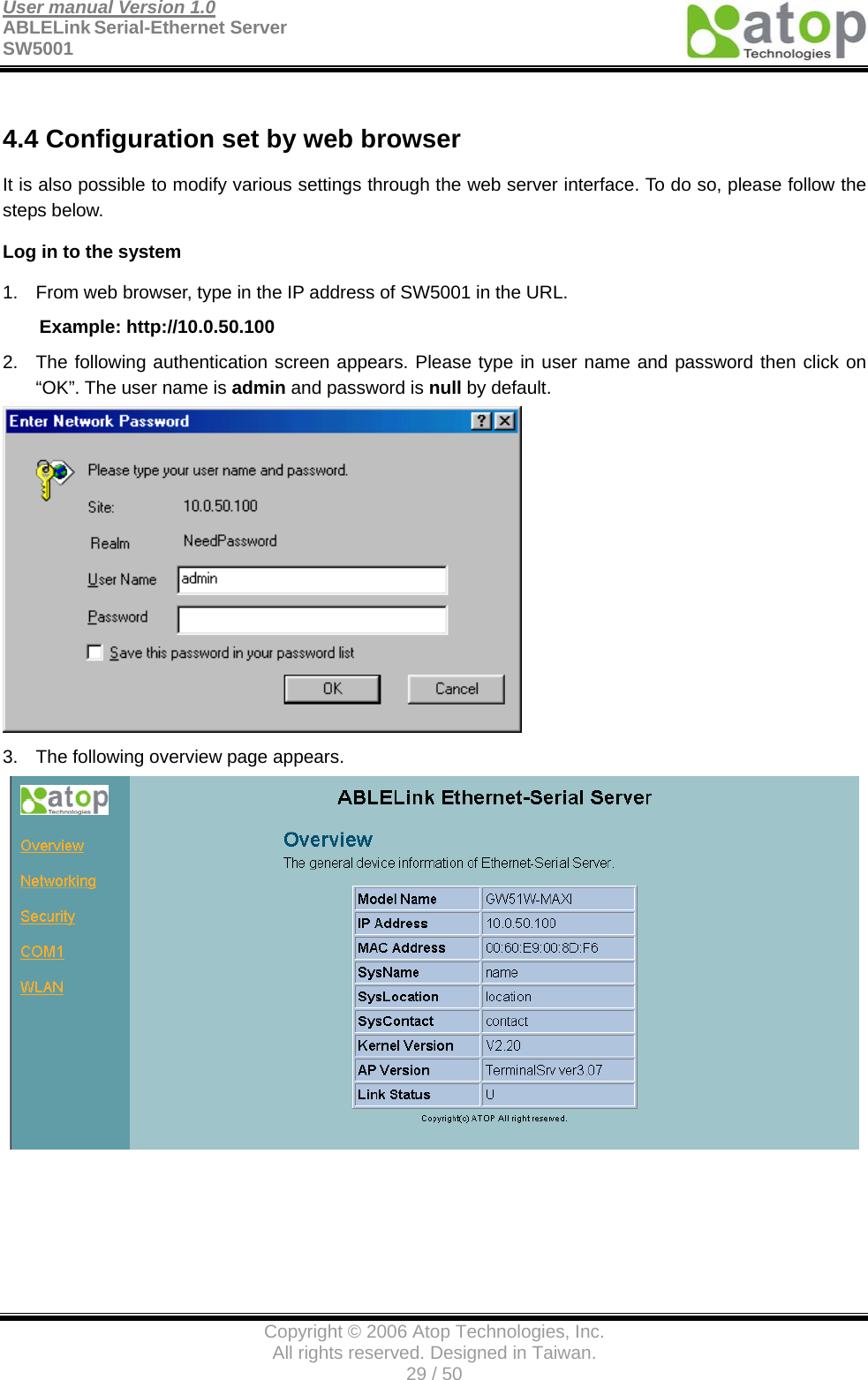
ATOP Technologies, INC. Wireless Serial Server Manual
UserManual.wiki
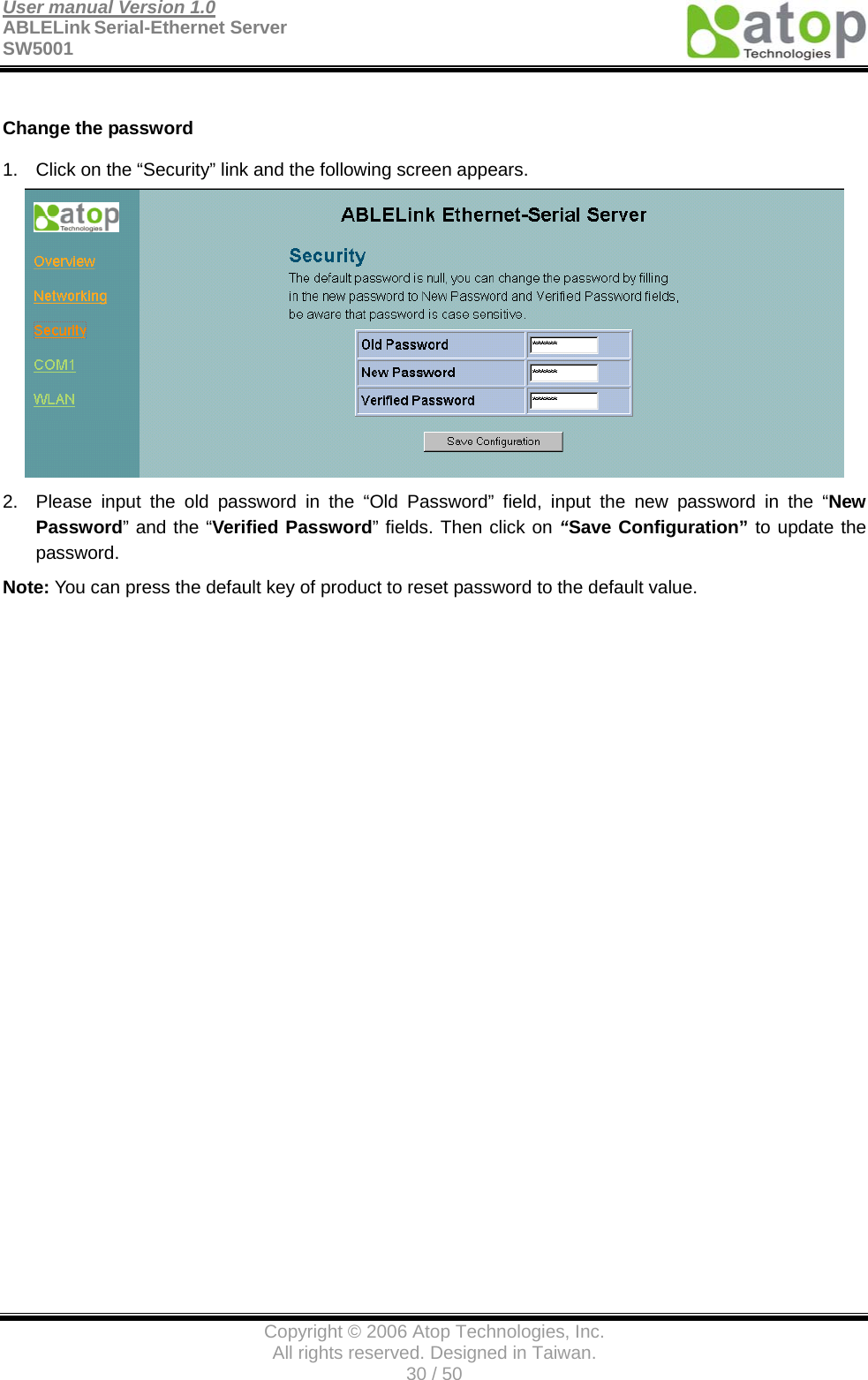
>
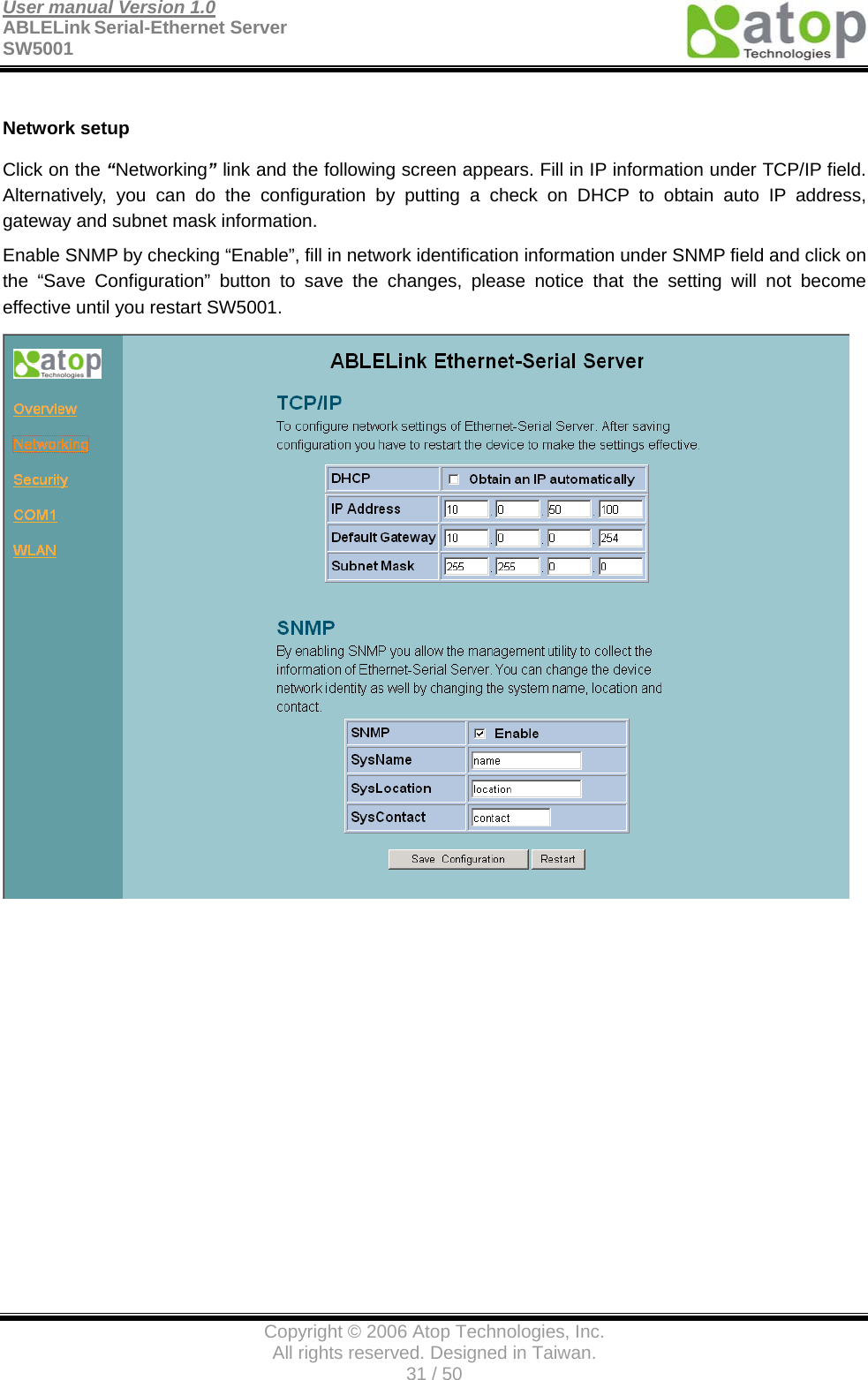
ATOP Technologies
>
SW5001 WGN1 User Manual
Manual
Navigation menu
Upload a User Manual
Namespaces
Wiki Guide
HTML
PDF
Info
Views
User Manual
Discussion / Help
Navigation