ATrack Technology ATPT1436 Car Tracker User Manual
ATrack Technology Inc. Car Tracker Users Manual
UserManual.wiki
>
ATrack Technology
>
ATPT1436 User Manual
Users Manual
Navigation menu
Upload a User Manual
Namespaces
Wiki Guide
HTML
PDF
Info
Views
User Manual
Discussion / Help
Navigation
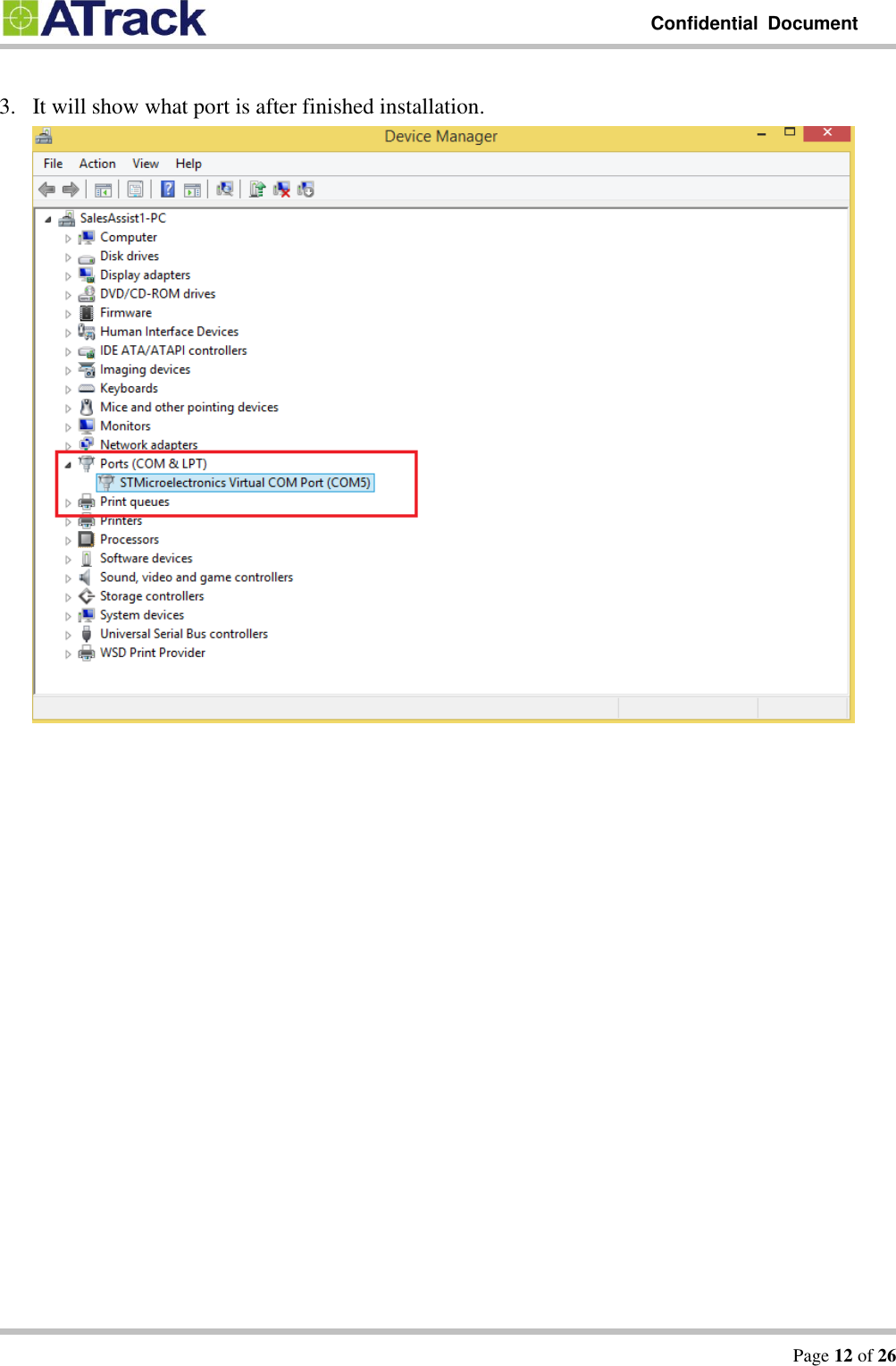
![Confidential Document Page 13 of 26 44..22.. FFiirrmmwwaarree UUppggrraaddee The following example shows how to connect the AS1 (E) through HyperTerminal and do firmware upgrade. You may use other popular terminal emulators such as Tera Term to establish a console session with the AS1 (E). (1) Give a name and click [OK] button.](https://usermanual.wiki/ATrack-Technology/ATPT1436/User-Guide-2493853-Page-13.png)
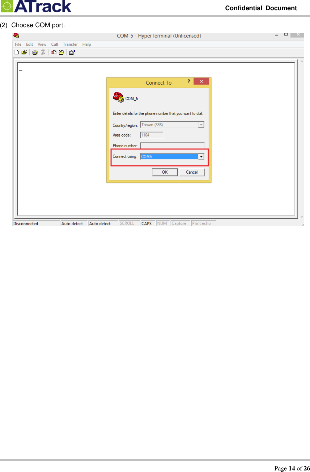
![Confidential Document Page 15 of 26 (3) Choose 57600,8,N,1 None flow control properties and click [OK] button.](https://usermanual.wiki/ATrack-Technology/ATPT1436/User-Guide-2493853-Page-15.png)
![Confidential Document Page 16 of 26 (4). Click [File] [Properties] [Settings] tab [ASCII Setup…] button](https://usermanual.wiki/ATrack-Technology/ATPT1436/User-Guide-2493853-Page-16.png)
![Confidential Document Page 17 of 26 (5) Checked the following options and click [OK] button](https://usermanual.wiki/ATrack-Technology/ATPT1436/User-Guide-2493853-Page-17.png)
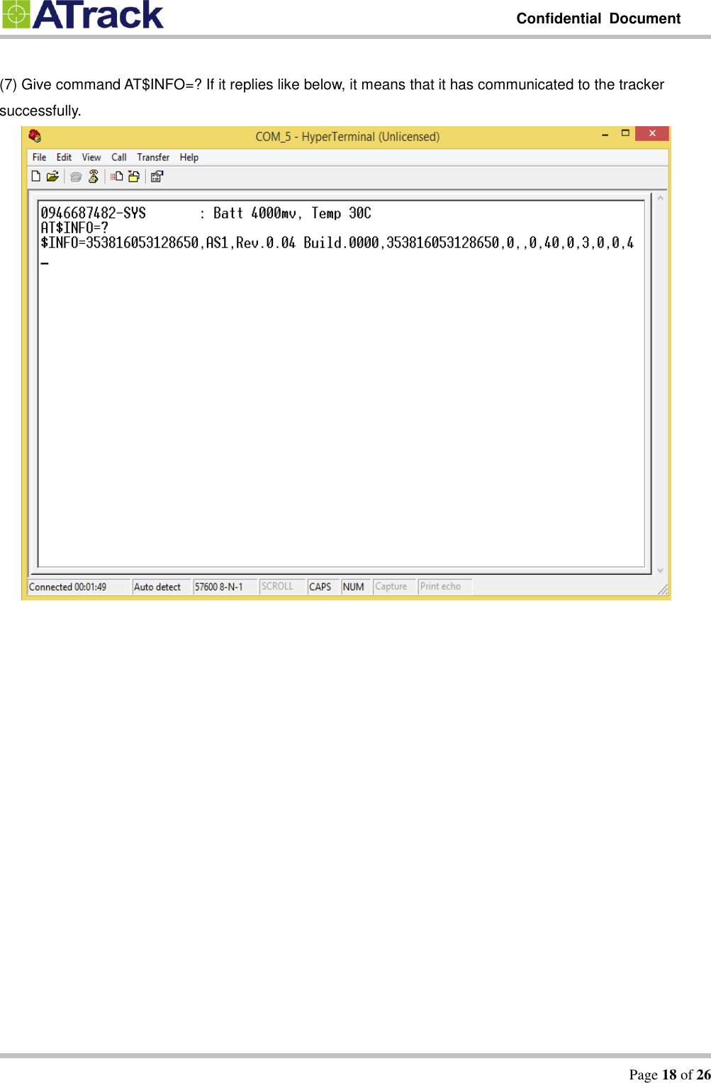
![Confidential Document Page 19 of 26 (8) Type the AT$FWDL command and press [Enter] key on your keyboard. Click on [Transfer] and select [Send File…]](https://usermanual.wiki/ATrack-Technology/ATPT1436/User-Guide-2493853-Page-19.png)
![Confidential Document Page 20 of 26 (9) Click on the [Browse] button to browse the firmware and select Ymodem from the Protocol drop-down list.](https://usermanual.wiki/ATrack-Technology/ATPT1436/User-Guide-2493853-Page-20.png)
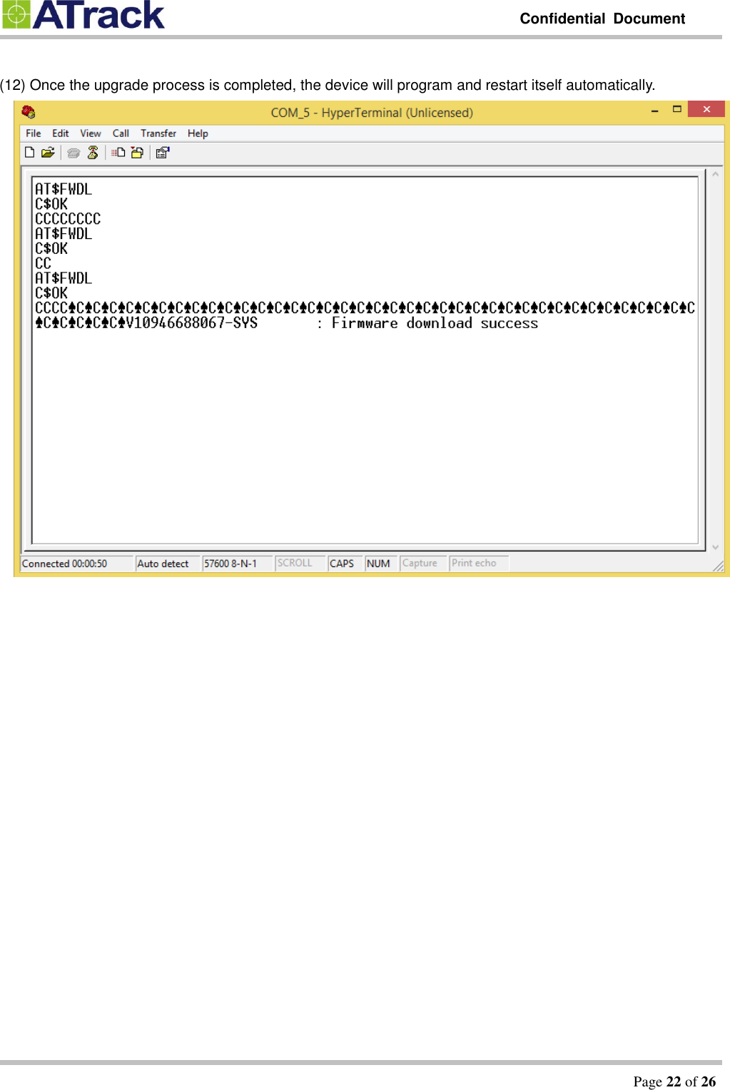
![Confidential Document Page 21 of 26 (10) Click on the [Send] button. The firmware file is being uploaded.](https://usermanual.wiki/ATrack-Technology/ATPT1436/User-Guide-2493853-Page-21.png)