ATrack Technology ATPT1436 Car Tracker User Manual
ATrack Technology Inc. Car Tracker Users Manual
Users Manual


Confidential Document
Page 2 of 26
Table of Contents
1. Notification .............................................................................................................................. 3
1.1. Disclaimer .................................................................................................................................... 3
1.2. Copyright ...................................................................................................................................... 3
1.3. Warning ........................................................................................................................................ 3
2. Overview .................................................................................................................................. 4
3. Installation ............................................................................................................................... 5
3.1. Package Content ......................................................................................................................... 5
3.2. USB Connector and LED indicators ............................................................................................ 6
3.3. Mounting Methods ....................................................................................................................... 8
3.3.1. Surface Screw Mount ...................................................................................................... 8
3.3.2. Magnet Mount ................................................................................................................. 8
4. Configuration .......................................................................................................................... 9
4.1. USB Driver Installation ................................................................................................................. 9
4.2. Firmware Upgrade ..................................................................................................................... 13
4.3. Connect a Device to a Remote Server ...................................................................................... 23
5. Appendix ................................................................................................................................ 24
5.1. Hardware Specification .............................................................................................................. 24
5.1.1. NdFeB Magnet 3000 Gauss±10% x 2pcs, stainless steel screws x 4pcs ....................... 25
5.2. FCC Regulations: ....................................................................................................................... 26

Confidential Document
Page 3 of 26
1
1.
.
N
No
ot
ti
if
fi
ic
ca
at
ti
io
on
n
1
1.
.1
1.
.
D
Di
is
sc
cl
la
ai
im
me
er
r
This document, and all other related products, such as device, firmware, and software, is developed by
ATrack Technology Inc. thoroughly. At the time of release, it is most compatible with specified firmware version.
Due to the functionalities of the devices are being developed and improved from time to time, the change in
the protocol, specification, and firmware functions are subjects to change without notice. ATrack Technology
Inc. is obligated to modify all the documentation without the limitation of time frame. A change notice shall be
released to ATrack Technology Inc. customers upon the completion of document modification.
ATrack Technology Inc. products are not intended to be used as life support or rescue equipments. ATrack
Technology Inc. is not liable for any loss or injury caused by using or referencing to any products. Any possible
means of using or integrating ATrack Technology Inc. products shall be avoided.
1
1.
.2
2.
.
C
Co
op
py
yr
ri
ig
gh
ht
t
ATrack Technology Inc. holds all parts of intellectual rights applicable in the copyright laws in all the countries.
Any or all parts of this document shall not be exposed to non-authorized party without any form of approval
from ATrack Technology Inc. Any forms, including but not limited to oral, copy, or internet sharing, of releasing
or exposing information to an unauthorized party shall be prohibited. ATrack Technology Inc. reserves the
rights of litigation in the violation of such copyright laws.
1
1.
.3
3.
.
W
Wa
ar
rn
ni
in
ng
g
Connecting the wire inputs can be hazardous to both the installer and your vehicle’s electrical system if not
done by an experienced installer. This document assumes you are aware of the inherent dangers of working
in and around a vehicle and have a working understanding of electricity.
Confidential Document
Page 4 of 26
2
2.
.
O
Ov
ve
er
rv
vi
ie
ew
w
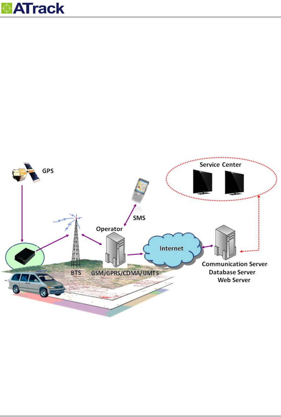
From the following diagram, the AS1 (E) GPS receiver receives incoming signals from each orbiting satellite.
These signals consist of information such as satellite’s position and the time that the signal was transmitted by
each satellite. The receiver analyzes these data in order to determine how far away each satellite is and it
uses the triangulation method to calculate the vehicle’s exact position. Once the positioning data along with
other event data are gathered, they will be transmitted to the service center across a Mobile network (e.g.
GSM/GPRS) or via SMS. The communication is bidirectional, which means you can control the AS1 (E)
remotely across a Mobile network or via SMS.
System Architecture
Confidential Document
Page 5 of 26
3
3.
.
I
In
ns
st
ta
al
ll
la
at
ti
io
on
n
3
3.
.1
1.
.
P
Pa
ac
ck
ka
ag
ge
e
C
Co
on
nt
te
en
nt
t
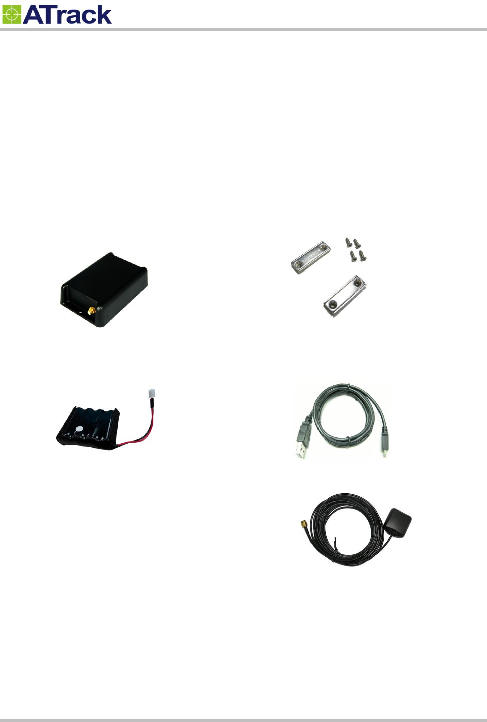
When you open the package, please verify that you received the following device and accessories:
AS1 (E) Device * 1
Battery * 1
Magnet Mount Kits (Optional)
USB Cable * 1
GPS Antenna * 1(AS1E only)
Confidential Document
Page 6 of 26
3
3.
.2
2.
.
U
US
SB
B
C
Co
on
nn
ne
ec
ct
to
or
r
a
an
nd
d
L
LE
ED
D
i
in
nd
di
ic
ca
at
to
or
rs
s
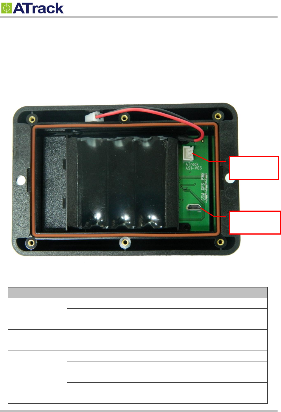
The following picture shows battery and USB connectors.
LED Indicators:
LED
Indication
Description
PWR (Green)
1 blink (0.2 sec.) in every 10 sec.
In full operation mode
2 blink (0.1 sec.) in every 2 sec.
In low battery mode (2.9V or below)
GPS (Red)
Off
Searching for GPS signal
1 blink (0.2 sec.) in every 2 sec.
Position get fixed
GSM (Red)
Off
GSM module off
Off
Searching for GSM signal
1 blink (0.2 sec.) in every 2 sec
Registered on GSM network
2 blinks in every 2 sec.
Connected to socket
Battery
connector
USB
connector

Confidential Document
Page 7 of 26
GPS Antenna Installation
The AS1 (E) determines its position by communicating with Global Positioning Satellites through an external
GPS antenna. The location where the AS1 (E) GPS antenna is installed will have great effect in the overall
performance of the GPS receiving. Please note that the following interior conditions may cause bad GPS
reception when a GPS antenna is installed inside interior of vehicle:
Windows with metallic tint
Windshield mounted radio antenna
Windows with solar reflective covers
The MP3/Dash camera FM transmitter may interfere with GPS reception
Confidential Document
Page 8 of 26
3
3.
.3
3.
.
M
Mo
ou
un
nt
ti
in
ng
g
M
Me
et
th
ho
od
ds
s
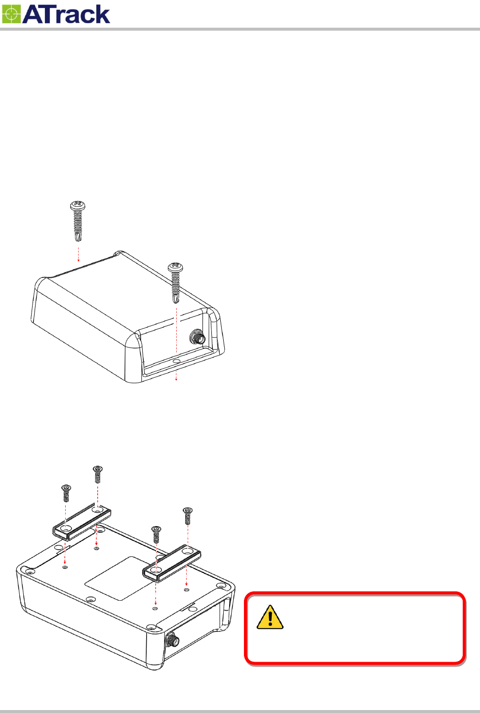
The AS1 (E) can be either surface or magnet mounted by using appropriate screws.
3.3.1. Surface Screw Mount
Use two #10 screws (diameter=4.8mm) to fix AS1 (E) on a surface.
3.3.2. Magnet Mount
Use magnet mount kits to install magnets on AS1 (E) device.
The magnets must be handled with care
to prevent personal injury as they are extremely
strong.

Confidential Document
Page 9 of 26
4
4.
.
C
Co
on
nf
fi
ig
gu
ur
ra
at
ti
io
on
n
You may explore great features on the AS1 (E) through AT commands. The commands can be sent to a
device via RS232, SMS or Mobile network (e.g. 3G/GPRS).
4
4.
.1
1.
.
U
US
SB
B
D
Dr
ri
iv
ve
er
r
I
In
ns
st
ta
al
ll
la
at
ti
io
on
n
In this section, we will demonstrate how to correctly install a USB driver on Windows platform.
The installation process will vary from one platform to another. Hence, you may see different
installation screens comparing to the ones which are shown here; however, most of these steps
involved during the installation remain the same.
S
Sy
ys
st
te
em
m
R
Re
eq
qu
ui
ir
re
em
me
en
nt
ts
s
The AS1 (E) supports the following operating systems: Windows 2000, Windows XP, Windows
Vista, Windows 7 and Windows 8.
I
In
ns
st
ta
al
ll
li
in
ng
g
a
an
n
U
Un
ns
si
ig
gn
ne
ed
d
D
Dr
ri
iv
ve
er
r
o
on
n
W
Wi
in
nd
do
ow
w
8
8
The USB Device Driver can be requested from the ATrack technical Support Team via email or
from the Partner Login section on the ATrack website at www.atrack.com.tw. Following is a
demonstration of how to install an unsigned USB driver on a Windows 8 platform through the
manual installation process.
Confidential Document
Page 10 of 26
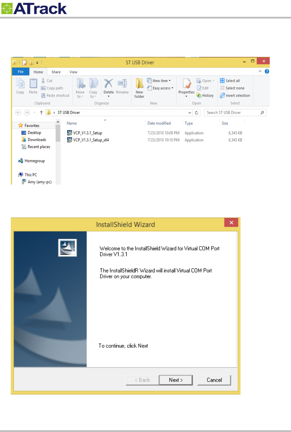
1. Unzipped ST USB Driver.rar and it has two exe files. If your environment is x64, please double
click VCP_V1.3.1_Setup_x64.exe. If not, please double click VCP_V1.3.1_Setup.exe.
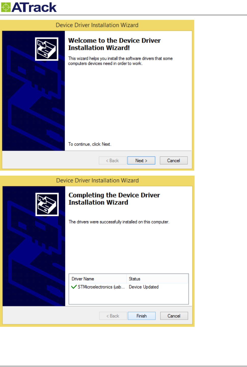
2. Please click Next and follow the instruction.
Confidential Document
Page 11 of 26
Confidential Document
Page 12 of 26
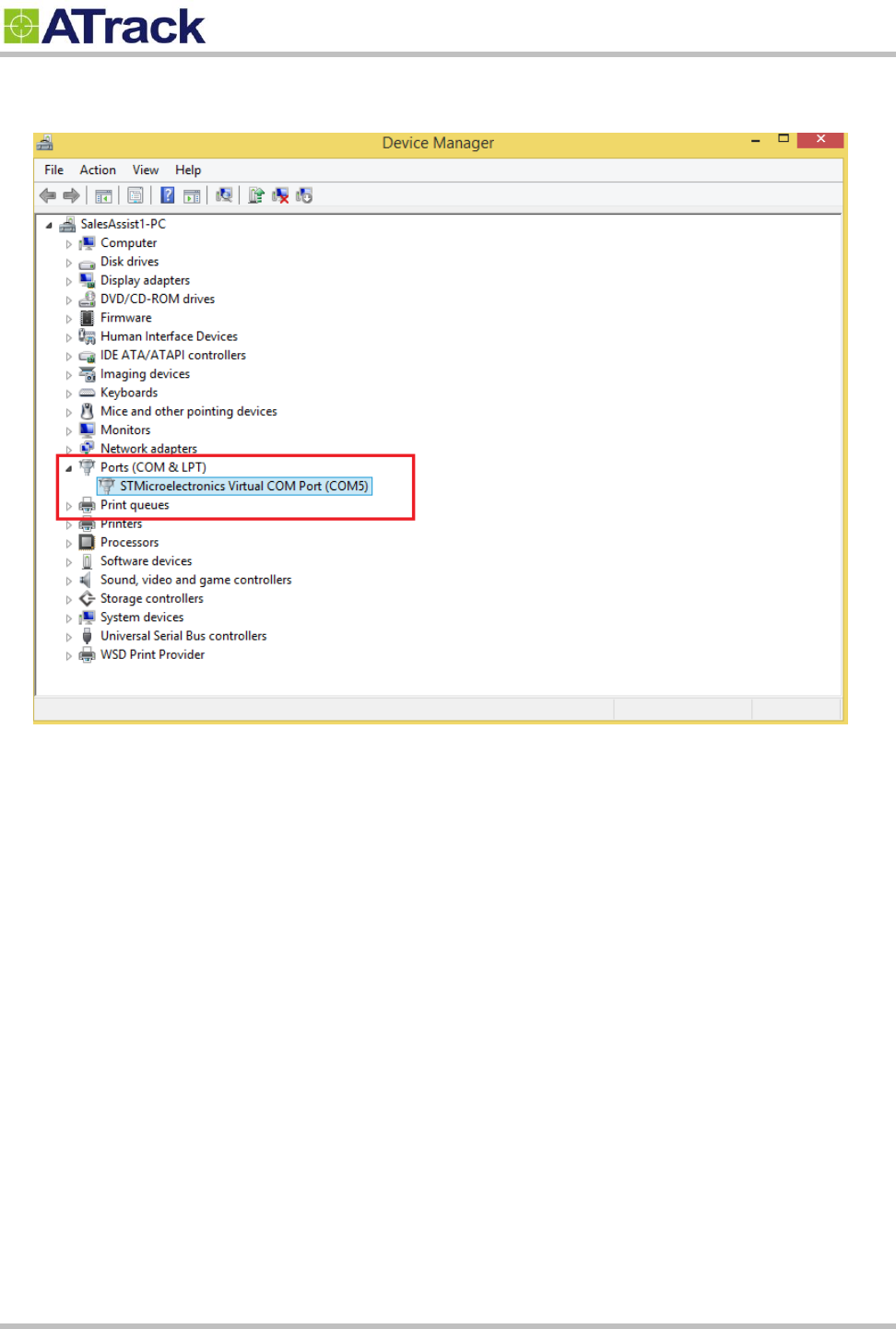
3. It will show what port is after finished installation.
Confidential Document
Page 13 of 26
4
4.
.2
2.
.
F
Fi
ir
rm
mw
wa
ar
re
e
U
Up
pg
gr
ra
ad
de
e
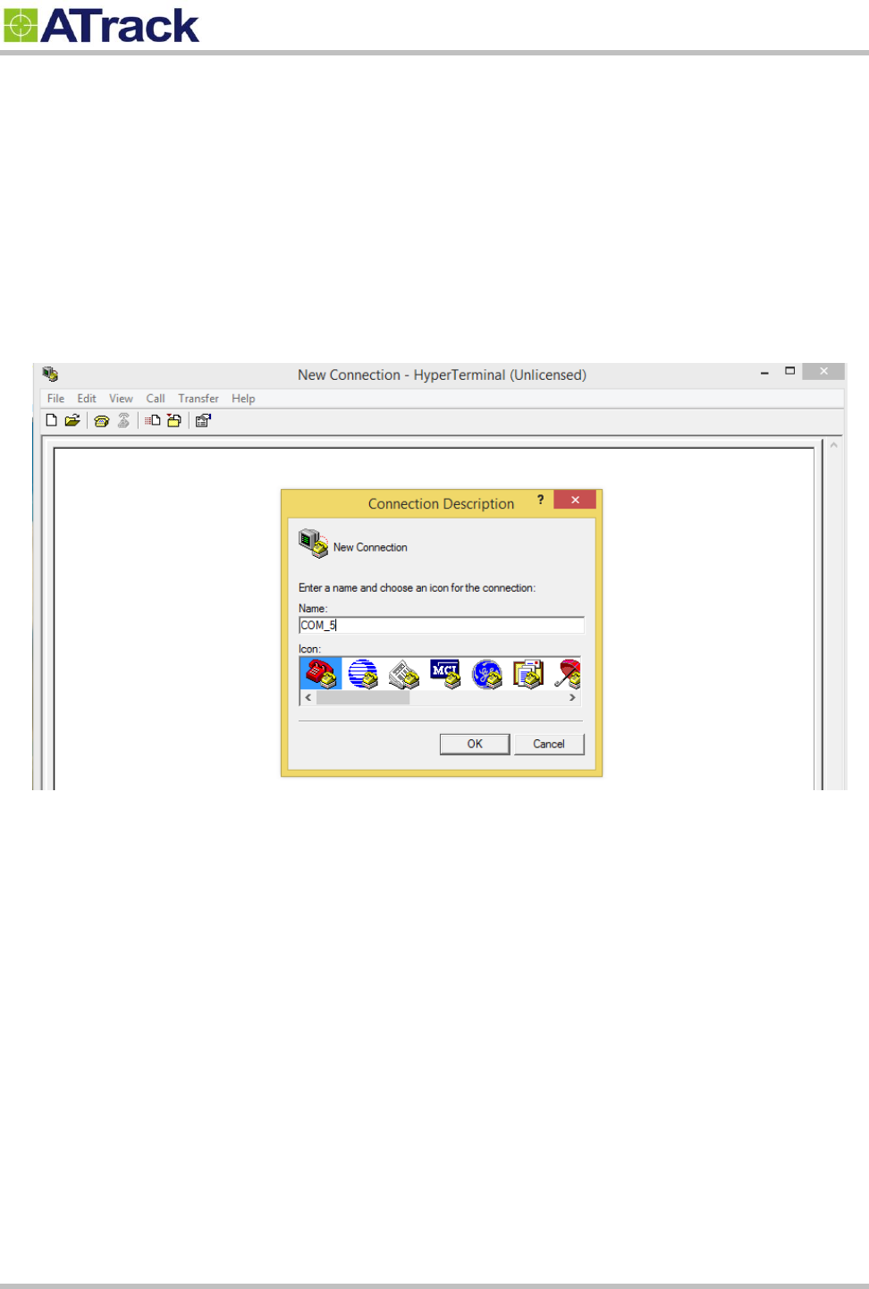
The following example shows how to connect the AS1 (E) through HyperTerminal and do firmware upgrade.
You may use other popular terminal emulators such as Tera Term to establish a console session with the AS1
(E).
(1) Give a name and click [OK] button.
Confidential Document
Page 14 of 26
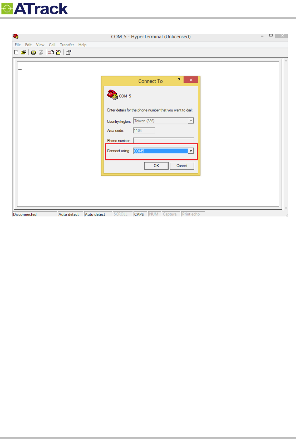
(2) Choose COM port.
Confidential Document
Page 15 of 26
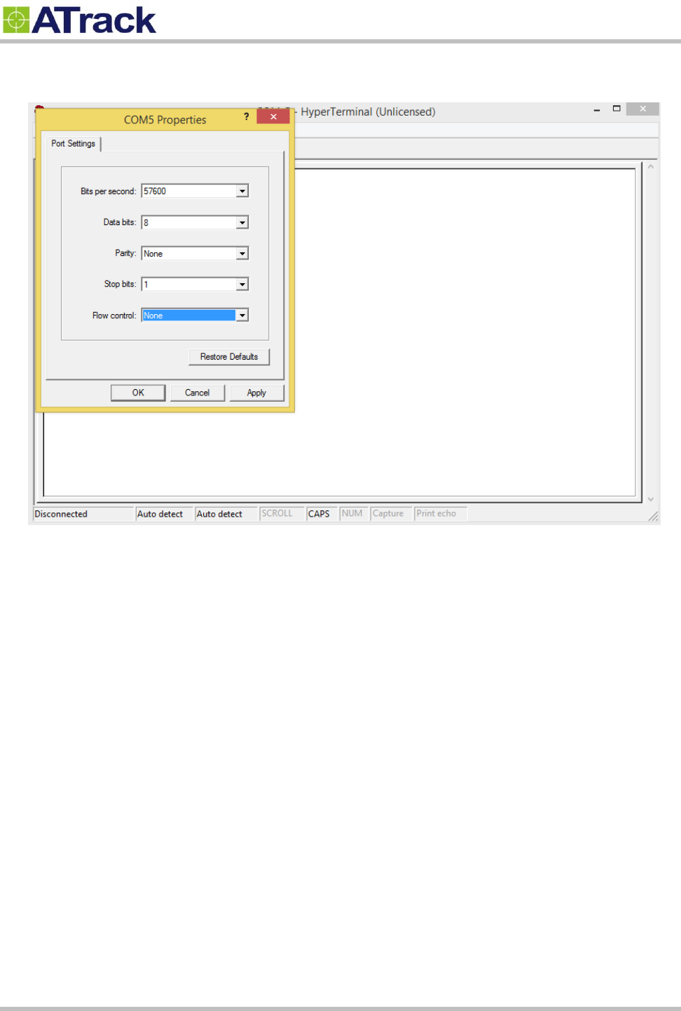
(3) Choose 57600,8,N,1 None flow control properties and click [OK] button.
Confidential Document
Page 16 of 26
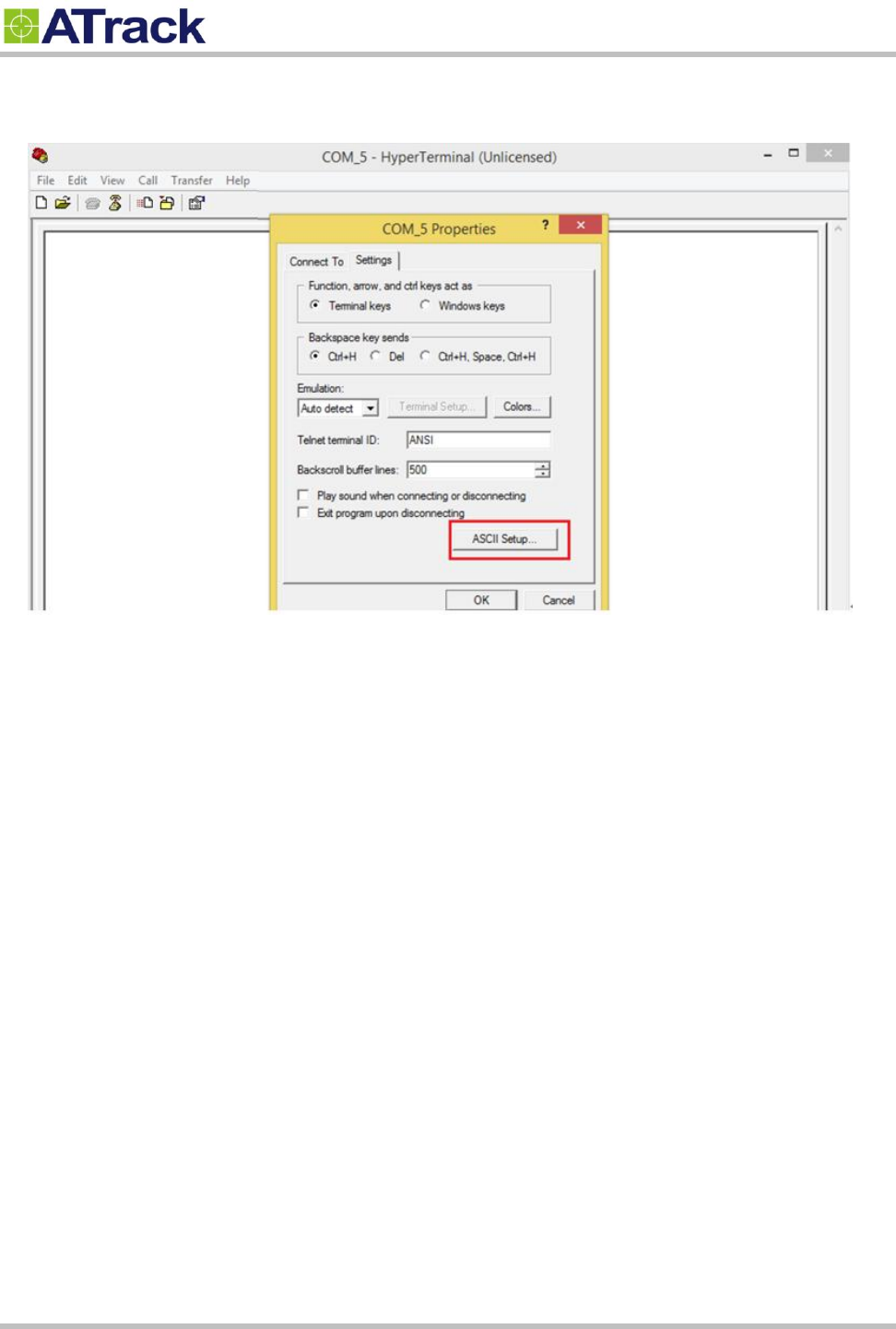
(4). Click [File] [Properties] [Settings] tab [ASCII Setup…] button
Confidential Document
Page 17 of 26
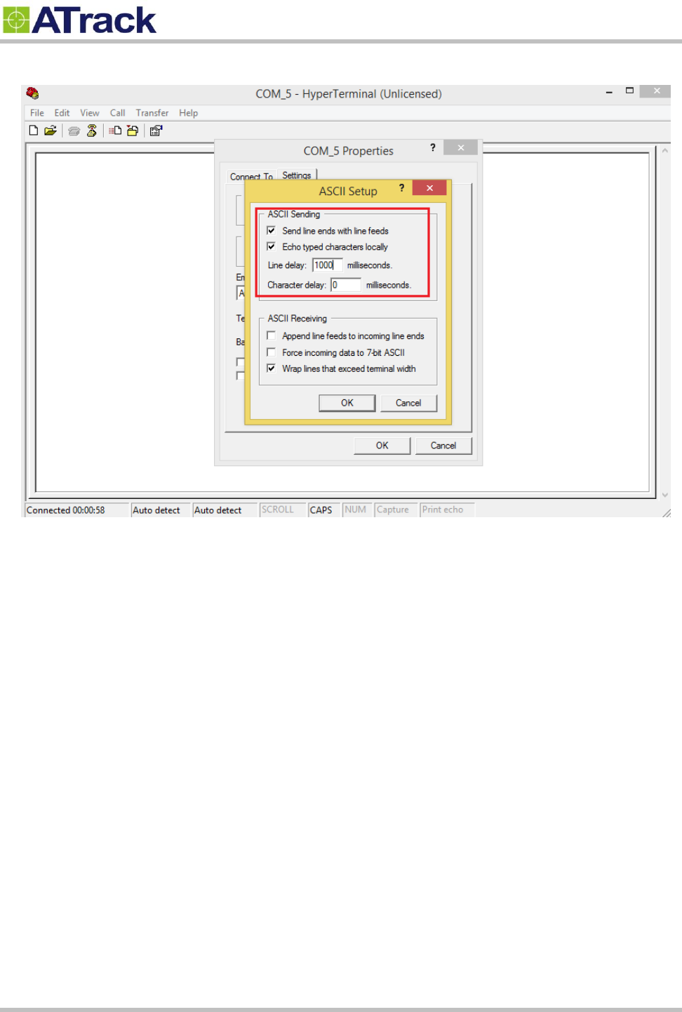
(5) Checked the following options and click [OK] button
Confidential Document
Page 18 of 26
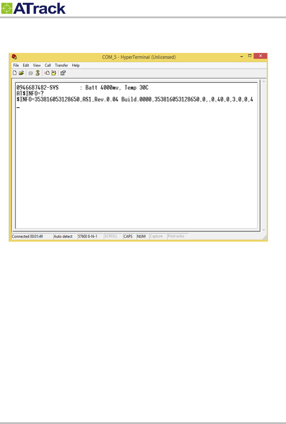
(7) Give command AT$INFO=? If it replies like below, it means that it has communicated to the tracker
successfully.
Confidential Document
Page 19 of 26
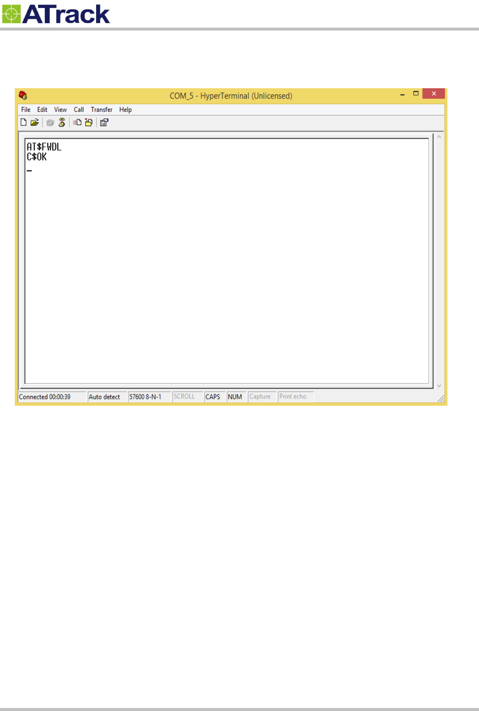
(8) Type the AT$FWDL command and press [Enter] key on your keyboard. Click on [Transfer] and select
[Send File…]
Confidential Document
Page 20 of 26
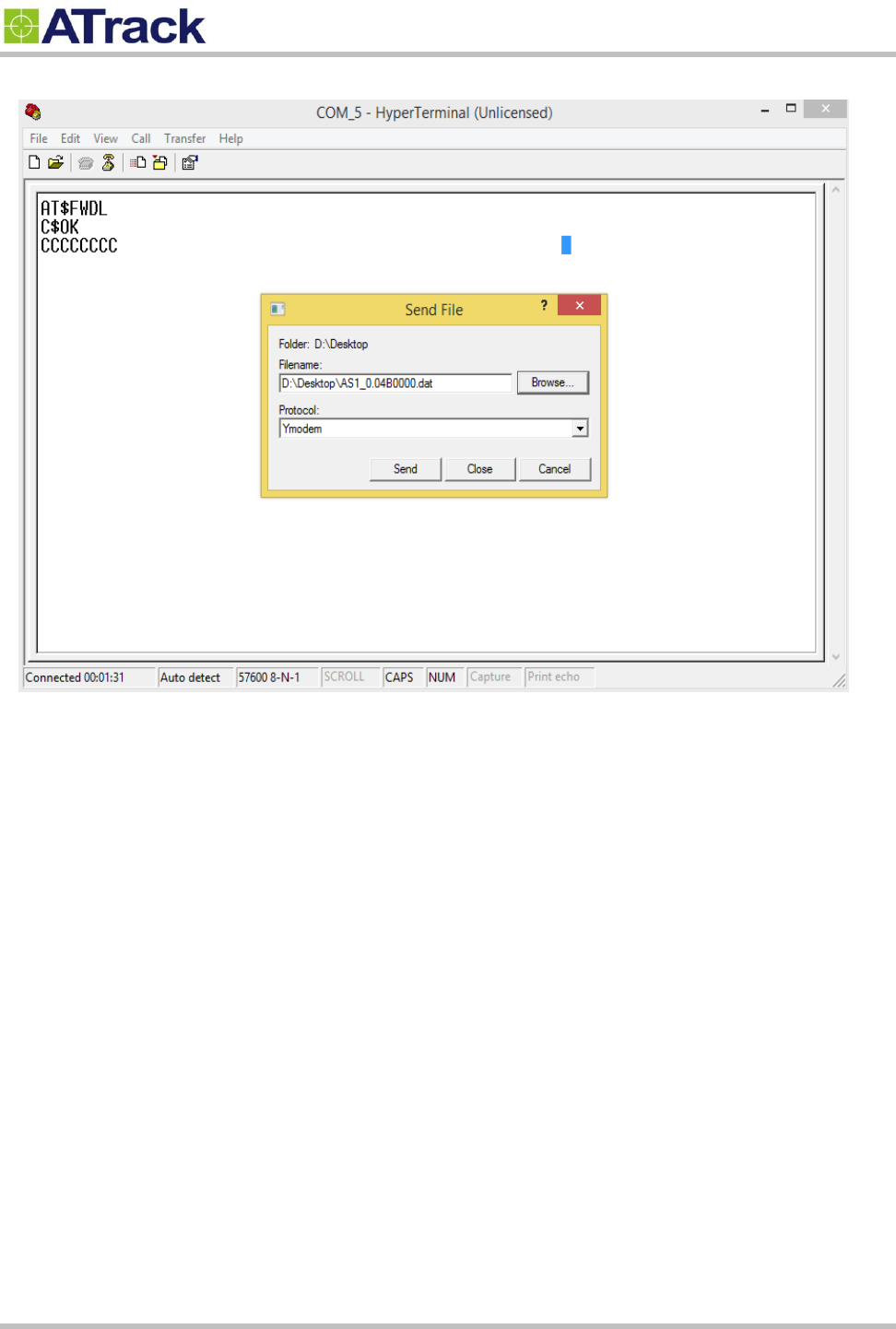
(9) Click on the [Browse] button to browse the firmware and select Ymodem from the Protocol drop-down list.
Confidential Document
Page 21 of 26
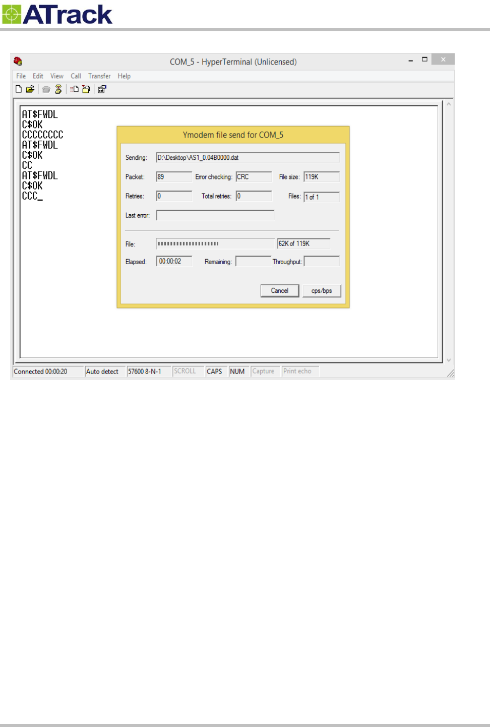
(10) Click on the [Send] button. The firmware file is being uploaded.
Confidential Document
Page 22 of 26
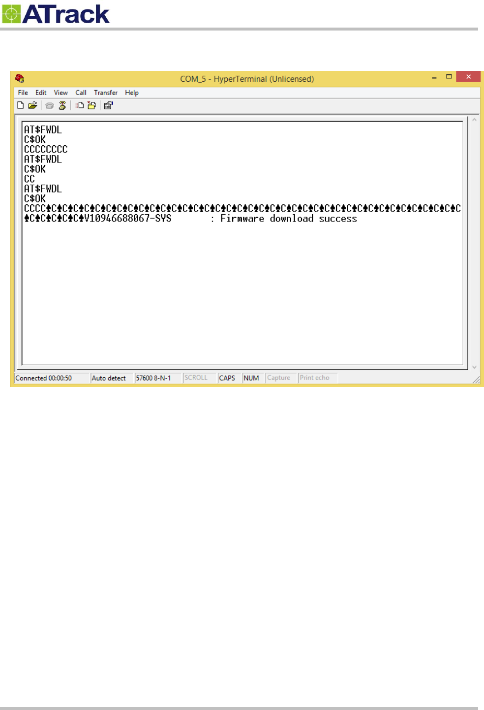
(12) Once the upgrade process is completed, the device will program and restart itself automatically.
Confidential Document
Page 23 of 26
4
4.
.3
3.
.
C
Co
on
nn
ne
ec
ct
t
a
a
D
De
ev
vi
ic
ce
e
t
to
o
a
a
R
Re
em
mo
ot
te
e
S
Se
er
rv
ve
er
r
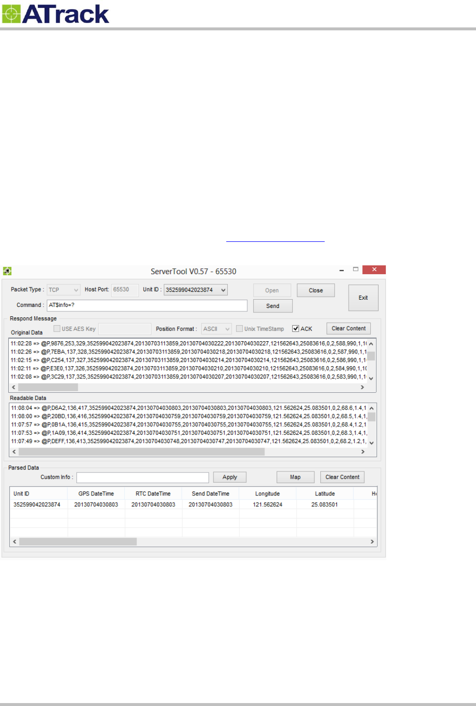
The GPRS or UMTS connection can either be enabled by typing the AT$GPRS command thorough the
terminal Tool. Once enabled, the ATrack ServerTool is then installed on a Windows PC in order to
communicate with the AS1 (E) remotely via a GPRS or UMTS network. The ServerTool is a remote server
application, which is mainly used for parsing data by translating binary formats into readable formats or other
testing purposes. Port forwarding is required if the PC is located behind a Broadband router or any other
firewall device or if it has third-party firewall software installed. The communication is bidirectional, which
means you can issue any AT command to the AS1 (E) by clicking the Send button. Please refer to the
following snapshot and the Port forwarding website: http://portforward.com/ for details.

Confidential Document
Page 24 of 26
5
5.
.
A
Ap
pp
pe
en
nd
di
ix
x
5
5.
.1
1.
.
H
Ha
ar
rd
dw
wa
ar
re
e
S
Sp
pe
ec
ci
if
fi
ic
ca
at
ti
io
on
n
Model Number
AS1
AS1E
Dimensions (L x W x
H)
120 x 80 x 32 mm
Weight
240g
235g
Housing
ABS+PC (UL 94 V-0), IP67 water proof
Operating
Temperature
-40℃ ~ +85℃
-40℃ ~ +85℃
Electrical Characteristics
Internal Battery
3.6V 8.8Ah Primary battery
Power Consumption
See Battery Life Estimation
Cellular Network Communication
Frequency(MHz)
GSM : Quad-band (850/900/1800/1900MHz)
CDMA : Dual-band (800/1900MHz Verizon/Sprint)
HSPA Dual-band : 850/1900 or 900/2100MHz
HSPA Global : 6-band (800/850/900/1700/1900/2100MHz)
Communication
SMS, TCP/IP, UDP/IP

Confidential Document
Page 25 of 26
Cellular Antenna
Internal Cellular antenna
SIM Card
1.8V/3V Mini SIM(2FF)
GPS Characteristics
Receiver
66 Acquisition Channels, L1 Band, C/A Code, -165dBm
sensitivity
Accuracy
3.0m CEP50 without SA
Data Acquisition Rate
1Hz
GPS Antenna
Internal GPS antenna
External GPS antenna
GPS Data Buffer
Capacity
Queue: 20,000 positions, Log: 95,000 positions
Accelerometer
3-Axis
Z,X,Y
Resolution
±2g, 10-bits resolution
Interface
USB
Internal USB connector
Standard Accessories
USB cable
USB cable (1.2m)
GPS Antenna
N/A
GPS Antenna(5.0m)
Optional Accessories
Magnet Mount Kits
5.1.1. NdFeB Magnet 3000 Gauss±10% x 2pcs, stainless
steel screws x 4pcs

Confidential Document
Page 26 of 26
5
5.
.2
2.
.
F
FC
CC
C
R
Re
eg
gu
ul
la
at
ti
io
on
ns
s:
:
This device complies with part 15 of the FCC Rules. Operation is subject to the following two
conditions: (1) This device may not cause harmful interference, and (2) this device must accept any
interference received, including interference that may cause undesired operation.
This device has been tested and found to comply with the limits for a Class B digital device, pursuant
to Part 15 of the FCC Rules. These limits are designed to provide reasonable protection against harmful
interference in a residential installation. This equipment generate, uses and can radiated radio
frequency energy and, if not installed and used in accordance with the instructions, may cause harmful
interference to radio communications. However, there is no guarantee that interference will not occur in
a particular installation. If this equipment does cause harmful interference to radio or television reception,
which can be determined by turning the equipment off and on, the user is encouraged to try to correct
the interference by one or more of the following measures:
-Reorient or relocate the receiving antenna.
-Increase the separation between the equipment and receiver.
-Connect the equipment into an outlet on a circuit different from that to which the receiver is connected.
-Consult the dealer or an experienced radio/TV technician for help.
Changes or modifications not expressly approved by the party responsible for compliance could void the
user‘s authority to operate the equipment.
RF Exposure Information
This device meets the government’s requirements for exposure to radio waves.
This device is designed and manufactured not to exceed the emission limits for exposure to radio
frequency (RF) energy set by the Federal Communications Commission of the U.S. Government.
This device complies with FCC radiation exposure limits set forth for an uncontrolled environment. In
order to avoid the possibility of exceeding the FCC radio frequency exposure limits, human proximity to
the antenna shall not be less than 20cm (8 inches) during normal operation.