ATrack Technology ATVT1301 CDMA GPS VEHICLE TRACKER User Manual
ATrack Technology Inc. CDMA GPS VEHICLE TRACKER
UserManual.wiki
>
ATrack Technology
>
ATVT1301 User Manual
User Manual
Navigation menu
Upload a User Manual
Namespaces
Wiki Guide
HTML
PDF
Info
Views
User Manual
Discussion / Help
Navigation
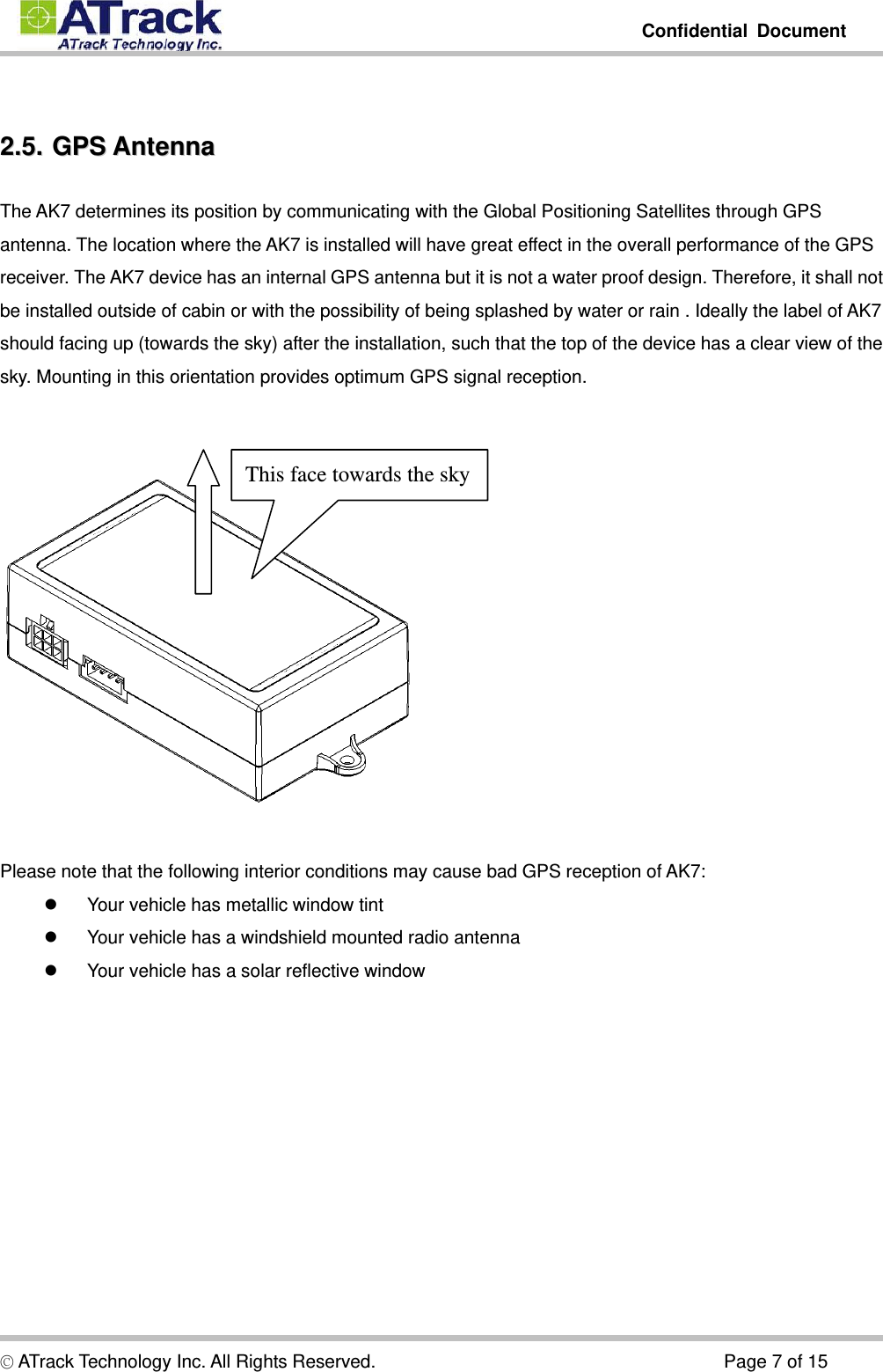
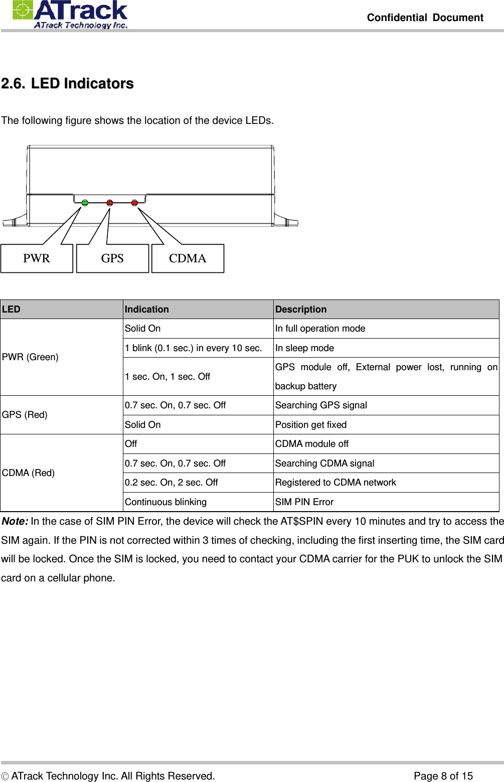
![Confidential Document © ATrack Technology Inc. All Rights Reserved. Page 9 of 15 33.. CCoonnffiigguurraattiioonn The device can be configured its parameters and behaviors by using AT commands. Please refer to ATrack Protocol Document for details. The device AT commands can be sent through RS232 port, SMS or TCP/UDP. 33..11.. CCoonnnneecctt ddeevviiccee ttoo HHyyppeerrTTeerrmmiinnaall The HyperTerminal is one of the most popular RS232 Terminal Emulator in Windows Platform. The other similar RS232 terminal emulator software can perform the same result. The following example shows how to connect the device to the HyperTerminal. (1) Run HyperTerminal program and choose COM port and click [Configure…] button.](https://usermanual.wiki/ATrack-Technology/ATVT1301/User-Guide-2010273-Page-9.png)
![Confidential Document © ATrack Technology Inc. All Rights Reserved. Page 10 of 15 (2) Choose 57600,8,N,1 None flow control properties and click [OK] button. (3) Click [File][Properties]](https://usermanual.wiki/ATrack-Technology/ATVT1301/User-Guide-2010273-Page-10.png)
![Confidential Document © ATrack Technology Inc. All Rights Reserved. Page 11 of 15 (4) Click [Settings] tab and [ASCII Setup…] button (5) Checked the following options and click [OK] button](https://usermanual.wiki/ATrack-Technology/ATVT1301/User-Guide-2010273-Page-11.png)
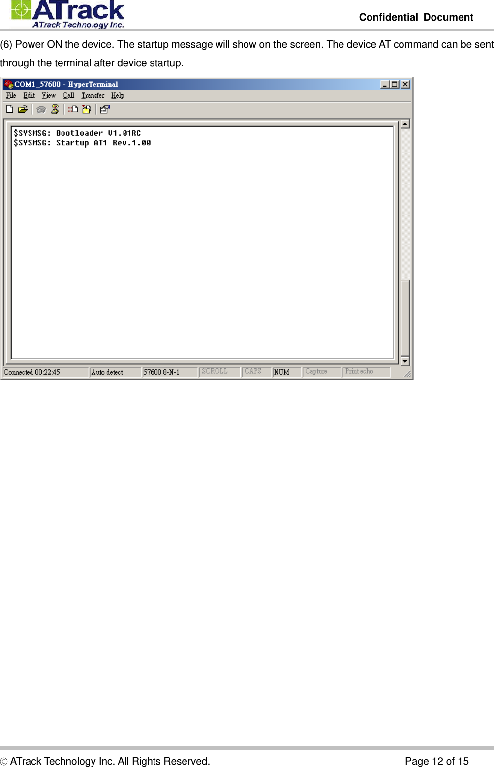
![Confidential Document © ATrack Technology Inc. All Rights Reserved. Page 13 of 15 44.. FFiirrmmwwaarree UUppggrraaddee The AK7device firmware can be upgraded by using RS232 serial port communication. The following is an example for how to upgrade firmware by serial port. (1) Run ATFWUpload program and select COM port and firmware file properly. Press [Open] button. (2) Power On the AK7device. The process will be started. (3) After the firmware has uploaded and verified successfully, the green completed message will be shown.](https://usermanual.wiki/ATrack-Technology/ATVT1301/User-Guide-2010273-Page-13.png)