ATrack Technology ATVT1301 CDMA GPS VEHICLE TRACKER User Manual
ATrack Technology Inc. CDMA GPS VEHICLE TRACKER
User Manual

AK7
User Manual
Revision: 05
Revision Date: 2012/06/25
ATrack Technology Inc.
3F., No. 88, Sec. 1, Neihu Rd., Neihu Dist.,
Taipei City 11493, Taiwan (R.O.C.)
Tel: +886-2-27975852
Fax: +886-2-27974030
http://www.atrack.com.tw

Confidential Document
© ATrack Technology Inc. All Rights Reserved. Page 2 of 15
Contents
1.Notification .............................................................................................................................. 3
1.1.Disclaimer .................................................................................................................................... 3
1.2.Copyright ...................................................................................................................................... 3
1.3.Warning ........................................................................................................................................ 3
2.Hardware ................................................................................................................................. 4
2.1.Package Content ......................................................................................................................... 4
2.2.SIM Card Installation .................................................................................................................... 4
2.3.Power I/O Connector ................................................................................................................... 5
2.4.Serial Port Connector ................................................................................................................... 6
2.5.GPS Antenna ............................................................................................................................... 7
2.6.LED Indicators ............................................................................................................................. 8
3.Configuration .......................................................................................................................... 9
3.1.Connect device to HyperTerminal ................................................................................................ 9
3.2.Connect the device to the remote server ................................................... 錯誤! 尚未定義書籤。
4.Firmware Upgrade ............................................................................................................... 13
5.Appendix ................................................................................................................................ 14
5.1.Hardware Specification .............................................................................................................. 14
5.2.FCC Regulations: ....................................................................................................................... 15

Confidential Document
© ATrack Technology Inc. All Rights Reserved. Page 3 of 15
1
1.
.
N
No
ot
ti
if
fi
ic
ca
at
ti
io
on
n
1
1.
.1
1.
.
D
Di
is
sc
cl
la
ai
im
me
er
r
This document, and all other related products, such as device, firmware, and software, is developed by
ATrack Technology Inc. thoroughly. At the time of release, it is most compatible with specified firmware version.
Due to the functionalities of the devices are being developed and improved from time to time, the change in
the protocol, specification, and firmware functions are subjects to change without notice. ATrack Technology
Inc. is obligated to modify all the documentation without the limitation of time frame. A change notice shall be
released to ATrack Technology Inc. customers upon the completion of document modification.
ATrack Technology Inc. products are not intended to be used as life support or rescue equipments. ATrack
Technology Inc. is not liable for any loss or injury caused by using or referencing to any products. Any possible
means of using or integrating ATrack Technology Inc. products shall be avoided.
1
1.
.2
2.
.
C
Co
op
py
yr
ri
ig
gh
ht
t
ATrack Technology Inc. holds all parts of intellectual rights applicable in the copyright laws in all the countries.
Any or all parts of this document shall not be exposed to non-authorized party without any form of approval
from ATrack Technology Inc. Any forms, including but not limited to oral, copy, or internet sharing, of releasing
or exposing information to an unauthorized party shall be prohibited. ATrack Technology Inc. reserves the
rights of litigation in the violation of such copyright laws.
1
1.
.3
3.
.
W
Wa
ar
rn
ni
in
ng
g
Connecting the wire inputs can be hazardous to both the installer and your vehicle’s electrical system if not
done by an experienced installer. This document assumes you are aware of the inherent dangers of working
in and around a vehicle and have a working understanding of electricity.
Confidential Document
© ATrack Technology Inc. All Rights Reserved. Page 4 of 15
2
2.
.
H
Ha
ar
rd
dw
wa
ar
re
e
2
2.
.1
1.
.
P
Pa
ac
ck
ka
ag
ge
e
C
Co
on
nt
te
en
nt
t
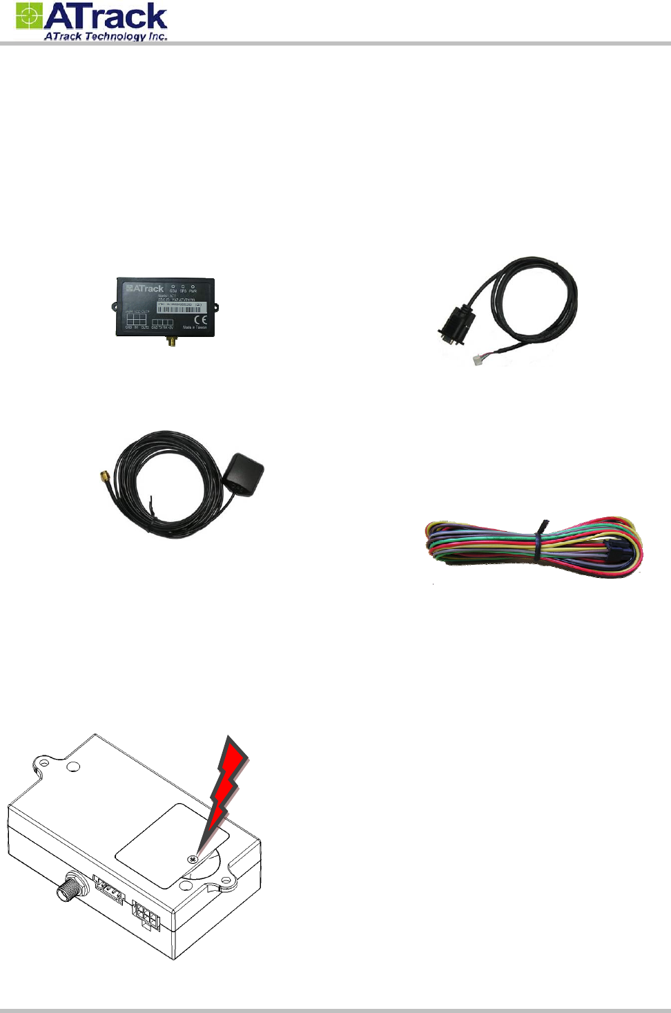
Each package contains the following device/accessories:
Device * 1 (one of the devices below)
AK7
GPS Antenna * 1 for AT1EONLY
Serial Cable * 1
Power/IO Cable * 1
2
2.
.2
2.
.
S
SI
IM
M
C
Ca
ar
rd
d
I
In
ns
st
ta
al
ll
la
at
ti
io
on
n
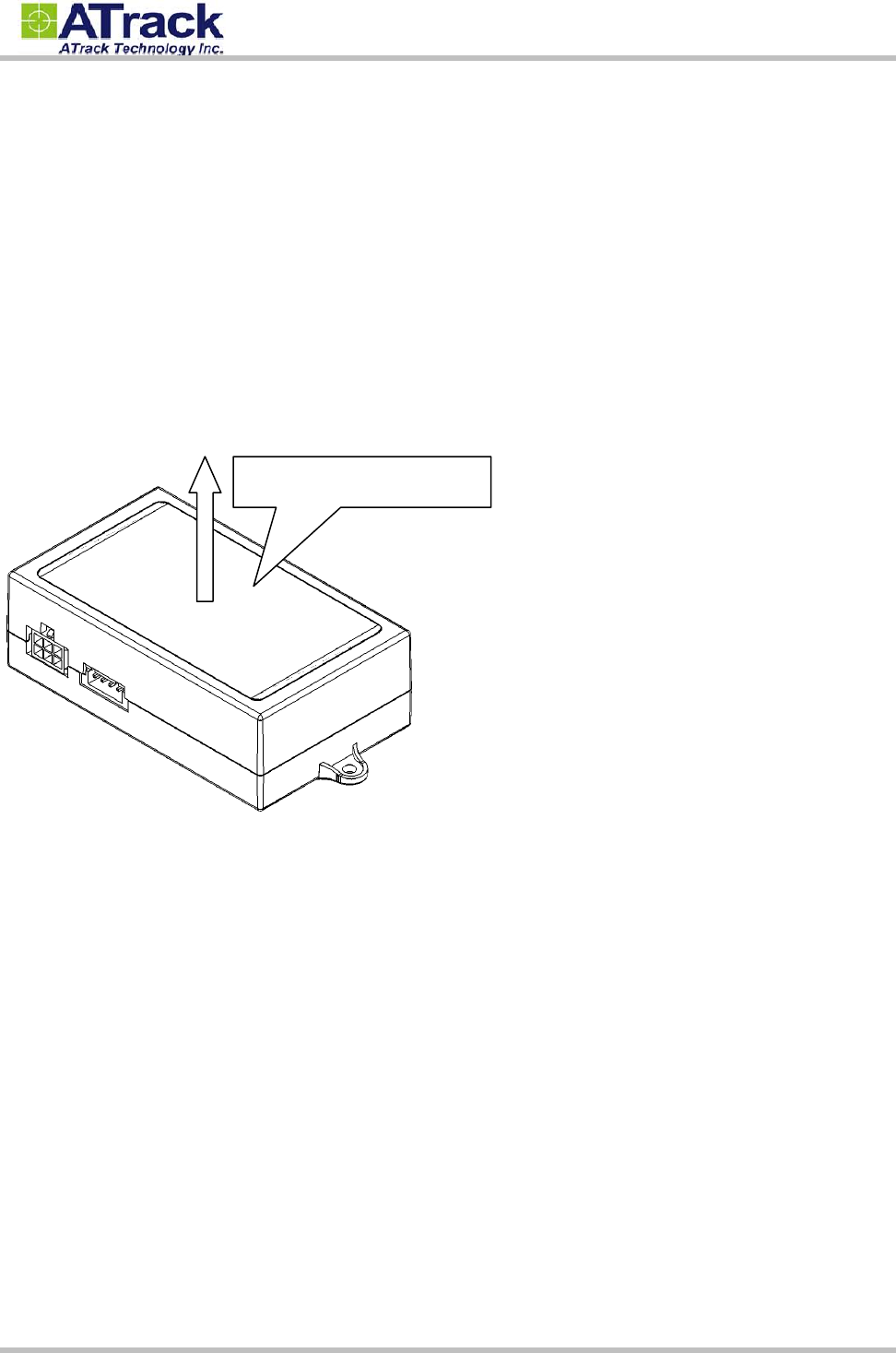
The AK7 supported 1.8V/3V universal SIM card which provided by worldwide CDMA operators. Unscrew the
SIM cover on the button of the AK7 device for SIM card installation.
Confidential Document
© ATrack Technology Inc. All Rights Reserved. Page 5 of 15
2
2.
.3
3.
.
P
Po
ow
we
er
r
I
I/
/O
O
C
Co
on
nn
ne
ec
ct
to
or
r
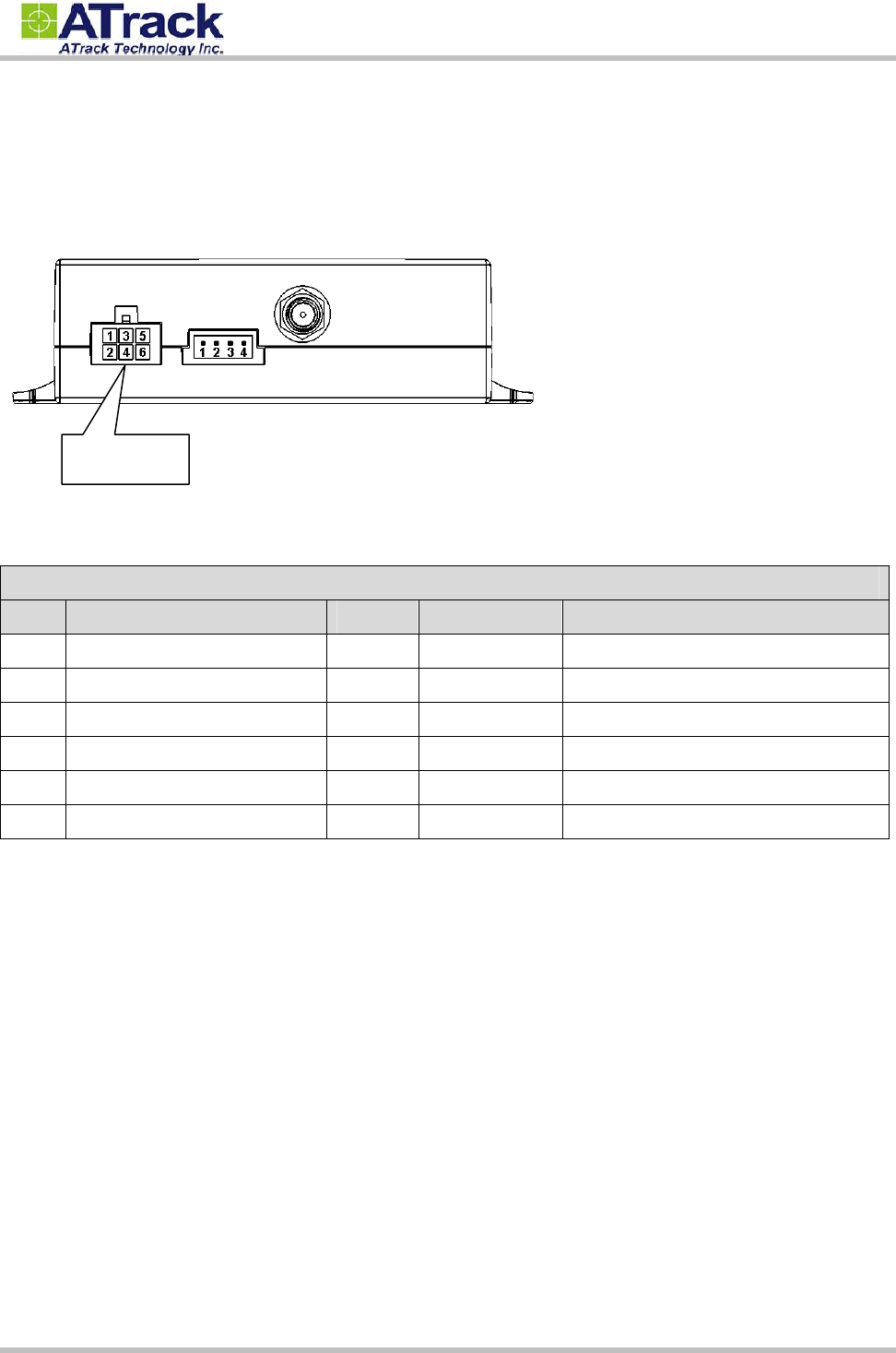
The following figure shows power I/O connector and its pin number of AK7
The following table shows its function of power I/O connector
Power I/O Connector
Pin# Function Color Designation Note
1 Main power input Red PWR DC 9V~40V input
2 Power ground Black GND
3 ACC Input Yellow ACC Ignition status positive trigger input
4 General Input1 Green IN1 Negative trigger input
5 General Output1 Brown O1 Open collector output (Max.300mA)
6 General Output2 Gray O2 Open collector output (Max.300mA)
Positive Inputs: ACC (Triggered when connects to V+ range from 3.7 ~ 40V)
Negative Inputs: IN1 (Triggered when connects to ground range from 0.8 ~ 0V)
All outputs are open collector type (grounded when enabled) with max. sink current of 300mA.
Power I/O
Confidential Document
© ATrack Technology Inc. All Rights Reserved. Page 6 of 15
2
2.
.4
4.
.
S
Se
er
ri
ia
al
l
P
Po
or
rt
t
C
Co
on
nn
ne
ec
ct
to
or
r
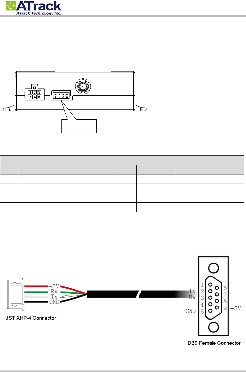
The following figure shows serial port connector and its pin number of AK7
The following table shows its function of serial port connector
Serial Port Connector
Pin# Function Color Designation Note
1 Power Ground Black GND
2 RS232 Transmit data output White TX
3 RS232 Receive data input Green RX
4* +5V Output for external accessories Red +5V DC5V Max.300mA Output
* Note that the +5V output pin cannot connect to the other power source or short circuit to power ground. If
the connected accessory requires more power, please use external power source instead.
The following figure shows the wire diagram of serial cable.
Serial Port
Confidential Document
© ATrack Technology Inc. All Rights Reserved. Page 7 of 15
2
2.
.5
5.
.
G
GP
PS
S
A
An
nt
te
en
nn
na
a
The AK7 determines its position by communicating with the Global Positioning Satellites through GPS
antenna. The location where the AK7 is installed will have great effect in the overall performance of the GPS
receiver. The AK7 device has an internal GPS antenna but it is not a water proof design. Therefore, it shall not
be installed outside of cabin or with the possibility of being splashed by water or rain . Ideally the label of AK7
should facing up (towards the sky) after the installation, such that the top of the device has a clear view of the
sky. Mounting in this orientation provides optimum GPS signal reception.
Please note that the following interior conditions may cause bad GPS reception of AK7:
Your vehicle has metallic window tint
Your vehicle has a windshield mounted radio antenna
Your vehicle has a solar reflective window
This face towards the sky
Confidential Document
© ATrack Technology Inc. All Rights Reserved. Page 8 of 15
2
2.
.6
6.
.
L
LE
ED
D
I
In
nd
di
ic
ca
at
to
or
rs
s
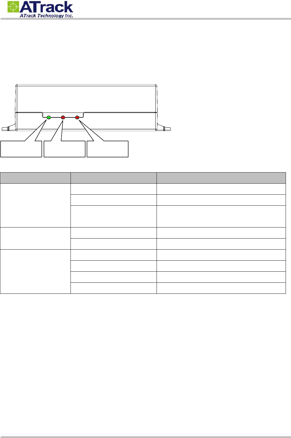
The following figure shows the location of the device LEDs.
LED Indication Description
PWR (Green)
Solid On In full operation mode
1 blink (0.1 sec.) in every 10 sec. In sleep mode
1 sec. On, 1 sec. Off GPS module off, External power lost, running on
backup battery
GPS (Red) 0.7 sec. On, 0.7 sec. Off Searching GPS signal
Solid On Position get fixed
CDMA (Red)
Off CDMA module off
0.7 sec. On, 0.7 sec. Off Searching CDMA signal
0.2 sec. On, 2 sec. Off Registered to CDMA network
Continuous blinking SIM PIN Error
Note: In the case of SIM PIN Error, the device will check the AT$SPIN every 10 minutes and try to access the
SIM again. If the PIN is not corrected within 3 times of checking, including the first inserting time, the SIM card
will be locked. Once the SIM is locked, you need to contact your CDMA carrier for the PUK to unlock the SIM
card on a cellular phone.
PWR GPS CDMA
Confidential Document
© ATrack Technology Inc. All Rights Reserved. Page 9 of 15
3
3.
.
C
Co
on
nf
fi
ig
gu
ur
ra
at
ti
io
on
n
The device can be configured its parameters and behaviors by using AT commands. Please refer to ATrack
Protocol Document for details. The device AT commands can be sent through RS232 port, SMS or TCP/UDP.
3
3.
.1
1.
.
C
Co
on
nn
ne
ec
ct
t
d
de
ev
vi
ic
ce
e
t
to
o
H
Hy
yp
pe
er
rT
Te
er
rm
mi
in
na
al
l
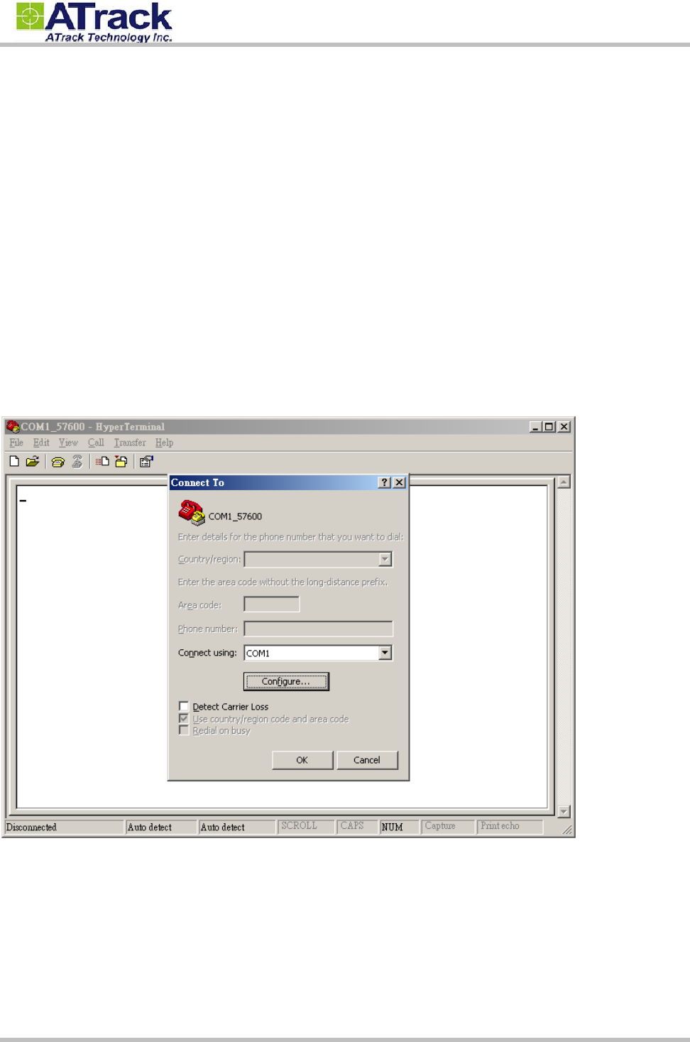
The HyperTerminal is one of the most popular RS232 Terminal Emulator in Windows Platform. The other
similar RS232 terminal emulator software can perform the same result. The following example shows how to
connect the device to the HyperTerminal.
(1) Run HyperTerminal program and choose COM port and click [Configure…] button.
Confidential Document
© ATrack Technology Inc. All Rights Reserved. Page 10 of 15
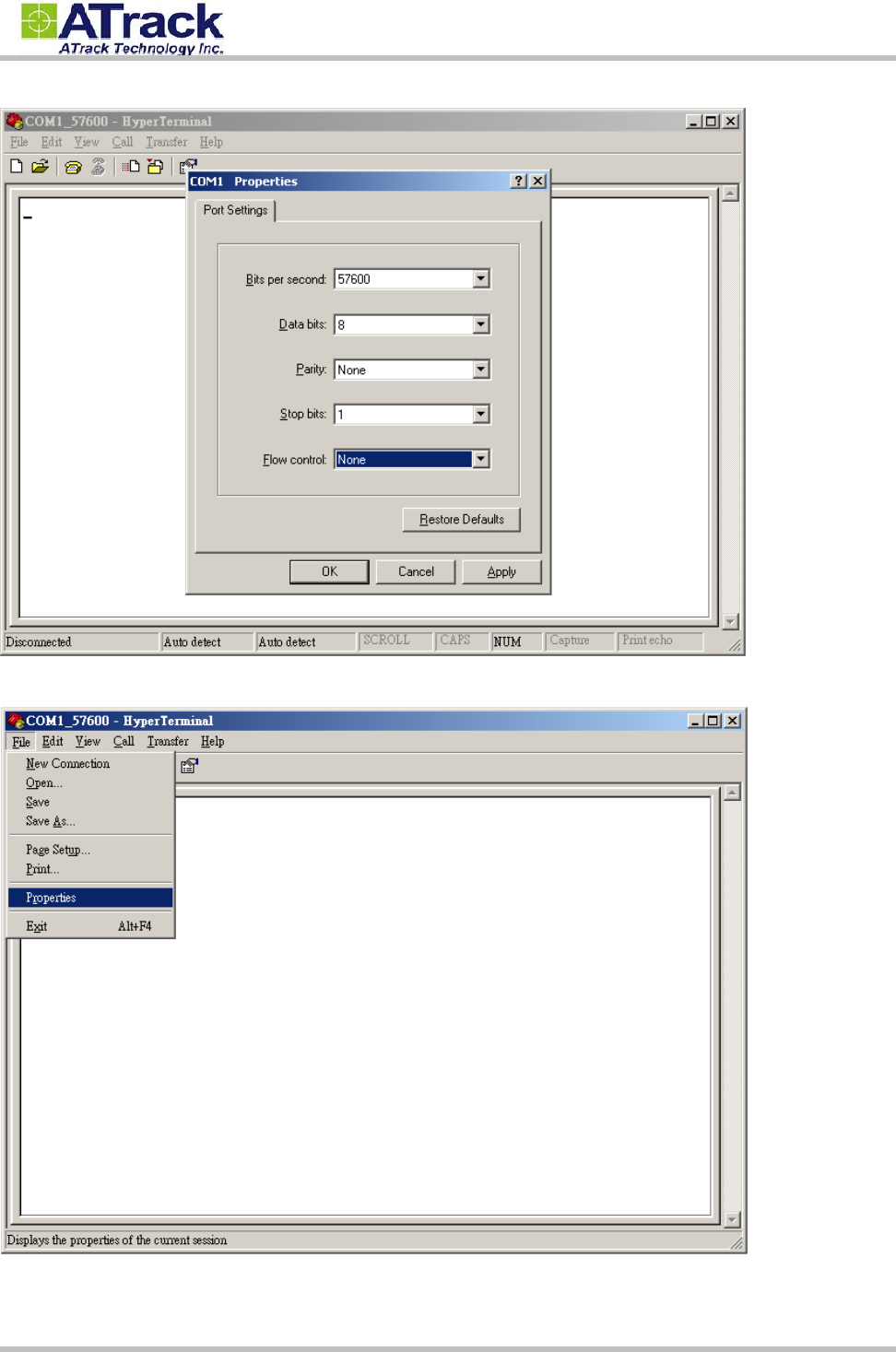
(2) Choose 57600,8,N,1 None flow control properties and click [OK] button.
(3) Click [File][Properties]
Confidential Document
© ATrack Technology Inc. All Rights Reserved. Page 11 of 15
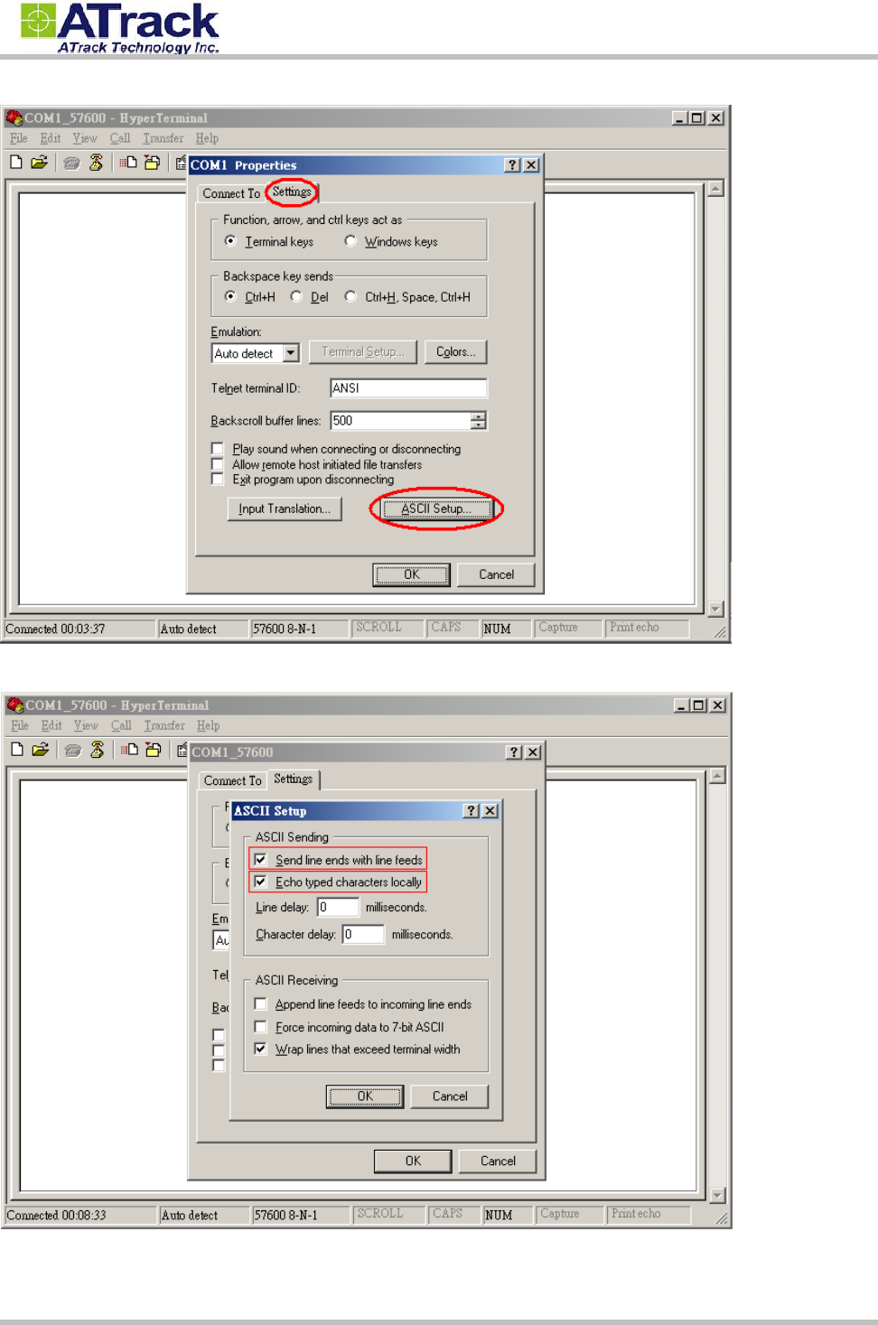
(4) Click [Settings] tab and [ASCII Setup…] button
(5) Checked the following options and click [OK] button
Confidential Document
© ATrack Technology Inc. All Rights Reserved. Page 12 of 15
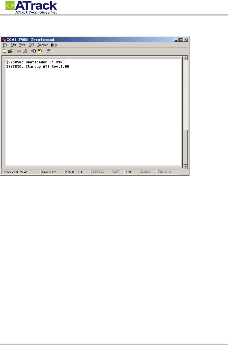
(6) Power ON the device. The startup message will show on the screen. The device AT command can be sent
through the terminal after device startup.
Confidential Document
© ATrack Technology Inc. All Rights Reserved. Page 13 of 15
4
4.
.
F
Fi
ir
rm
mw
wa
ar
re
e
U
Up
pg
gr
ra
ad
de
e
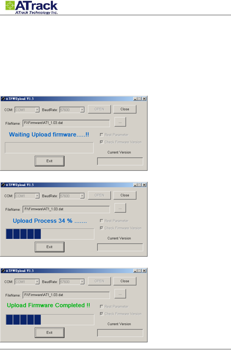
The AK7device firmware can be upgraded by using RS232 serial port communication. The following is an
example for how to upgrade firmware by serial port.
(1) Run ATFWUpload program and select COM port and firmware file properly. Press [Open] button.
(2) Power On the AK7device. The process will be started.
(3) After the firmware has uploaded and verified successfully, the green completed message will be shown.

Confidential Document
© ATrack Technology Inc. All Rights Reserved. Page 14 of 15
5
5.
.
A
Ap
pp
pe
en
nd
di
ix
x
5
5.
.1
1.
.
H
Ha
ar
rd
dw
wa
ar
re
e
S
Sp
pe
ec
ci
if
fi
ic
ca
at
ti
io
on
n
AK7
Physical Characteristics
Dimension 80 * 48 * 26 mm
CDMA Module Bual band CDMA 850/1900MHz
GPS Module High Sensitivity (65 Channel)
GPS Antennas (for AT1E) SMA Connector Type
Shock Sensor Built-In
Real-Time Clock Built-In
Memory Capacity 2MB
Casing High Heat Grade ABS
Electrical Characteristics
Power Source 8-40 VDC
Power Consumption Operational 100 mA @ 12VDC
Sleep 20 mA @ 12VDC
Deep Sleep 8 mA @ 12VDC
I/O Characteristics
Device I/O Ports Positive Input 1 (Triggering voltage: 3.7 ~ 40V)
Negative Input 1 (Triggering voltage: 0 ~ 0.8V)
Negative Outputs 2 (Open Collector Type @ 300mAMAX)
Serial Configurable 1
Baud rates 1200, 2400, 4800, 9600, 19200, 38400,
57600, 115200 bps
Environmental Characteristics
Operation Temperature -30 ~ +70°C (Note: Temp. up to +85°C with
extreme condition)
Storage Temperature -40 ~ +85°C
Relative Humidity 5 ~ 95%

Confidential Document
© ATrack Technology Inc. All Rights Reserved. Page 15 of 15
5
5.
.2
2.
.
F
FC
CC
C
R
Re
eg
gu
ul
la
at
ti
io
on
ns
s:
:
This device complies with part 15 of the FCC Rules. Operation is subject to the following two
conditions: (1) This device may not cause harmful interference, and (2) this device must accept any
interference received, including interference that may cause undesired operation.
This device has been tested and found to comply with the limits for a Class B digital device, pursuant
to Part 15 of the FCC Rules. These limits are designed to provide reasonable protection against harmful
interference in a residential installation. This equipment generates, uses and can radiated radio
frequency energy and, if not installed and used in accordance with the instructions, may cause harmful
interference to radio communications. However, there is no guarantee that interference will not occur in
a particular installation If this equipment does cause harmful interference to radio or television reception,
which can be determined by turning the equipment off and on, the user is encouraged to try to correct
the interference by one or more of the following measures:
-Reorient or relocate the receiving antenna.
-Increase the separation between the equipment and receiver.
-Connect the equipment into an outlet on a circuit different from that to which the receiver is connected.
-Consult the dealer or an experienced radio/TV technician for help.
Changes or modifications not expressly approved by the party responsible for compliance could void the
user‘s authority to operate the equipment.
RF Exposure Information
This device meets the government’s requirements for exposure to radio waves.
This device is designed and manufactured not to exceed the emission limits for exposure to radio
frequency (RF) energy set by the Federal Communications Commission of the U.S. Government.
This device complies with FCC radiation exposure limits set forth for an uncontrolled environment. In
order to avoid the possibility of exceeding the FCC radio frequency exposure limits, human proximity to
the antenna shall not be less than 20cm (8 inches) during normal operation.