ATrack Technology ATVT1303 CDMA GPS VEHICLE TRACKER User Manual
ATrack Technology Inc. CDMA GPS VEHICLE TRACKER
UserManual.wiki
>
ATrack Technology
>
ATVT1303 User Manual
User Manual
Navigation menu
Upload a User Manual
Namespaces
Wiki Guide
HTML
PDF
Info
Views
User Manual
Discussion / Help
Navigation

![Confidential Document © ATrack Technology Inc. All Rights Reserved. Page 8 of 15 (2) Enter a name for the connection (3) Choose COM port and click [Configure…] button.](https://usermanual.wiki/ATrack-Technology/ATVT1303/User-Guide-2010408-Page-8.png)
![Confidential Document © ATrack Technology Inc. All Rights Reserved. Page 9 of 15 (4) Choose 57600,8,N,1 None flow control properties and click [OK] button. (5) Click [File][Properties]](https://usermanual.wiki/ATrack-Technology/ATVT1303/User-Guide-2010408-Page-9.png)
![Confidential Document © ATrack Technology Inc. All Rights Reserved. Page 10 of 15 (6) Click [Settings] tab and [ASCII Setup…] button (7) Checked the following option and click [OK] button](https://usermanual.wiki/ATrack-Technology/ATVT1303/User-Guide-2010408-Page-10.png)
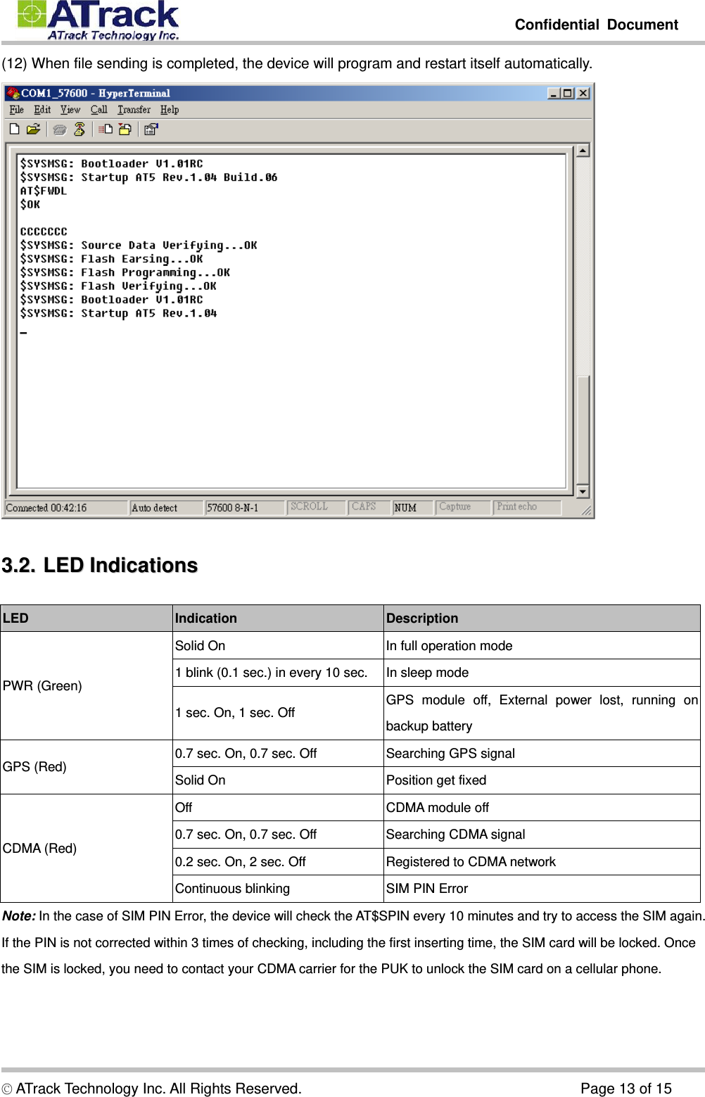
![Confidential Document © ATrack Technology Inc. All Rights Reserved. Page 11 of 15 (8) Power ON the device. The startup message will show on the screen. (9) Type “AT$FWDL” command and press [Enter] key. Choose [Transfer][Send File…]](https://usermanual.wiki/ATrack-Technology/ATVT1303/User-Guide-2010408-Page-11.png)
![Confidential Document © ATrack Technology Inc. All Rights Reserved. Page 12 of 15 (10) Choose the firmware filename which is provided by ATrack and select [Ymodem] Protocol option and click [Send] button. (11) When [Send] button is clicked, the file transfer progress will show as below:](https://usermanual.wiki/ATrack-Technology/ATVT1303/User-Guide-2010408-Page-12.png)