ATrack Technology ATVT1427 Car Tracker User Manual AS3 AS3E
ATrack Technology Inc. Car Tracker AS3 AS3E
UserManual.wiki
>
ATrack Technology
>
ATVT1427 User Manual
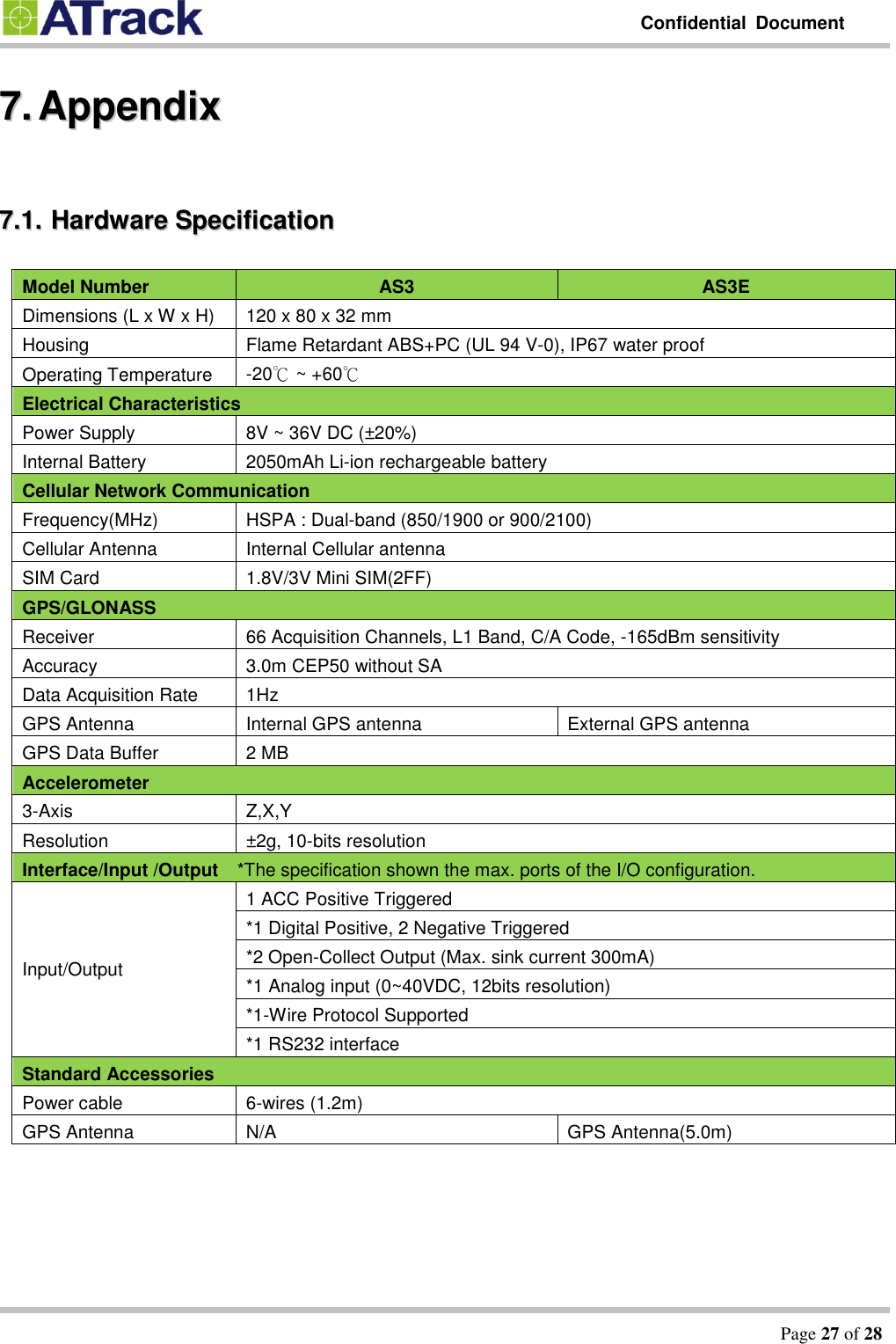
User Manual.pdf
Navigation menu
Upload a User Manual
Namespaces
Wiki Guide
HTML
PDF
Info
Views
User Manual
Discussion / Help
Navigation
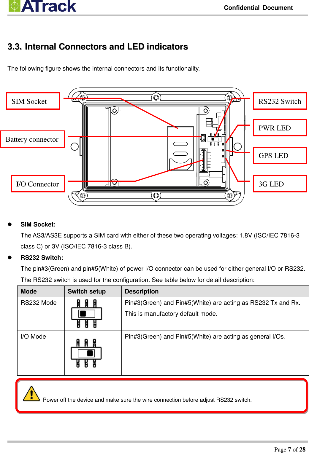
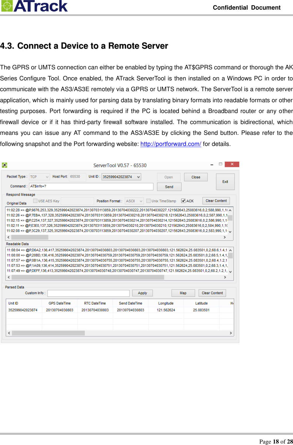
![Confidential Document Page 14 of 28 44..22.. CCoonnnneecctt aa DDeevviiccee UUssiinngg HHyyppeerrTTeerrmmiinnaall The following example shows how to connect the AS3/AS3E through HyperTerminal. You may use other popular terminal emulators such as Putty or Tera Term Pro to establish a console session with the AS3/AS3E. (1) Run HyperTerminal program and choose COM port and click [Configure…] button.](https://usermanual.wiki/ATrack-Technology/ATVT1427/User-Guide-2383651-Page-14.png)
![Confidential Document Page 15 of 28 (2) Choose 57600,8,N,1 None flow control properties and click [OK] button. (3) Click [File][Properties]](https://usermanual.wiki/ATrack-Technology/ATVT1427/User-Guide-2383651-Page-15.png)
![Confidential Document Page 16 of 28 (4) Click [Settings] tab and [ASCII Setup…] button (5) Checked the following options and click [OK] button](https://usermanual.wiki/ATrack-Technology/ATVT1427/User-Guide-2383651-Page-16.png)
![Confidential Document Page 20 of 28 66.. FFiirrmmwwaarree UUppggrraaddee The device firmware can be upgraded via RS232 or through the FTP protocol. Following is an example of firmware upgrade via RS232. (1) Run the AK Series Configure Tool and click on the [Connect] button. (2) Select the correct COM port and the Baud Rate (57600) from drop-down lists. Click on the [Ok] button to close Setting.](https://usermanual.wiki/ATrack-Technology/ATVT1427/User-Guide-2383651-Page-20.png)
![Confidential Document Page 21 of 28 (3) Click on the [Read] button to read out data from the device. (4) From the following snapshot, the data is being read out.](https://usermanual.wiki/ATrack-Technology/ATVT1427/User-Guide-2383651-Page-21.png)
![Confidential Document Page 22 of 28 (5) Click on the [OK] button to close the message box.](https://usermanual.wiki/ATrack-Technology/ATVT1427/User-Guide-2383651-Page-22.png)
![Confidential Document Page 23 of 28 (6) Click on [System Configuration] (7) Click on [Firmware Upgrade]](https://usermanual.wiki/ATrack-Technology/ATVT1427/User-Guide-2383651-Page-23.png)
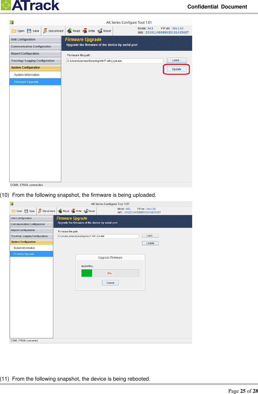
![Confidential Document Page 24 of 28 (8) Click on the [Load…] button to browse the firmware file where you saved. In the following example, AS3/AS3E_1.04.dat is selected and click on the [Open] button to close the window. (9) Click on the [Update] button to upgrade the firmware.](https://usermanual.wiki/ATrack-Technology/ATVT1427/User-Guide-2383651-Page-24.png)
![Confidential Document Page 26 of 28 (12) Click on the [OK] button to close the message box.](https://usermanual.wiki/ATrack-Technology/ATVT1427/User-Guide-2383651-Page-26.png)