ATrack Technology ATVT1427 Car Tracker User Manual AS3 AS3E
ATrack Technology Inc. Car Tracker AS3 AS3E
User Manual.pdf


Confidential Document
Page 2 of 28
Table of Contents
1. Notification .............................................................................................................................. 3
1.1. Disclaimer .................................................................................................................................... 3
1.2. Copyright ...................................................................................................................................... 3
1.3. Warning ........................................................................................................................................ 3
2. Overview .................................................................................................................................. 4
3. Installation ............................................................................................................................... 5
3.1. Package Content ......................................................................................................................... 5
3.2. Power I/O Connector ................................................................................................................... 6
3.3. Internal Connectors and LED indicators ...................................................................................... 7
3.4. DB9 Connector Wiring Diagram................................................................................................... 9
3.4.1. Using ATrack Serial Cable .............................................................................................. 9
3.4.2. Connecting DB9 Female Connector ............................................................................. 10
3.5. GPS Antenna Installation ........................................................................................................... 11
3.6. Mounting Methods ..................................................................................................................... 12
3.6.1. Surface Screw Mount .................................................................................................... 12
3.6.2. Magnet Mount ............................................................................................................... 12
4. Configuration ........................................................................................................................ 13
4.1. Set up a Device Using the AK Series Configure Tool ................................................................ 13
4.2. Connect a Device Using HyperTerminal .................................................................................... 14
4.3. Connect a Device to a Remote Server ...................................................................................... 18
5. AT$IOCG Command Reference.......................................................................................... 19
5.1. Configure or Query I/O Pin Characteristics ............................................................................... 19
6. Firmware Upgrade ............................................................................................................... 20
7. Appendix ................................................................................................................................ 27
7.1. Hardware Specification .............................................................................................................. 27
7.2. FCC Regulations: ....................................................................................................................... 28

Confidential Document
Page 3 of 28
1
1.
.
N
No
ot
ti
if
fi
ic
ca
at
ti
io
on
n
1
1.
.1
1.
.
D
Di
is
sc
cl
la
ai
im
me
er
r
This document, and all other related products, such as device, firmware, and software, is developed by
ATrack Technology Inc. thoroughly. At the time of release, it is most compatible with specified firmware version.
Due to the functionalities of the devices are being developed and improved from time to time, the change in
the protocol, specification, and firmware functions are subjects to change without notice. ATrack Technology
Inc. is obligated to modify all the documentation without the limitation of time frame. A change notice shall be
released to ATrack Technology Inc. customers upon the completion of document modification.
ATrack Technology Inc. products are not intended to be used as life support or rescue equipments. ATrack
Technology Inc. is not liable for any loss or injury caused by using or referencing to any products. Any possible
means of using or integrating ATrack Technology Inc. products shall be avoided.
1
1.
.2
2.
.
C
Co
op
py
yr
ri
ig
gh
ht
t
ATrack Technology Inc. holds all parts of intellectual rights applicable in the copyright laws in all the countries.
Any or all parts of this document shall not be exposed to non-authorized party without any form of approval
from ATrack Technology Inc. Any forms, including but not limited to oral, copy, or internet sharing, of releasing
or exposing information to an unauthorized party shall be prohibited. ATrack Technology Inc. reserves the
rights of litigation in the violation of such copyright laws.
1
1.
.3
3.
.
W
Wa
ar
rn
ni
in
ng
g
Connecting the wire inputs can be hazardous to both the installer and your vehicle’s electrical system if not
done by an experienced installer. This document assumes you are aware of the inherent dangers of working
in and around a vehicle and have a working understanding of electricity.
Confidential Document
Page 4 of 28
2
2.
.
O
Ov
ve
er
rv
vi
ie
ew
w
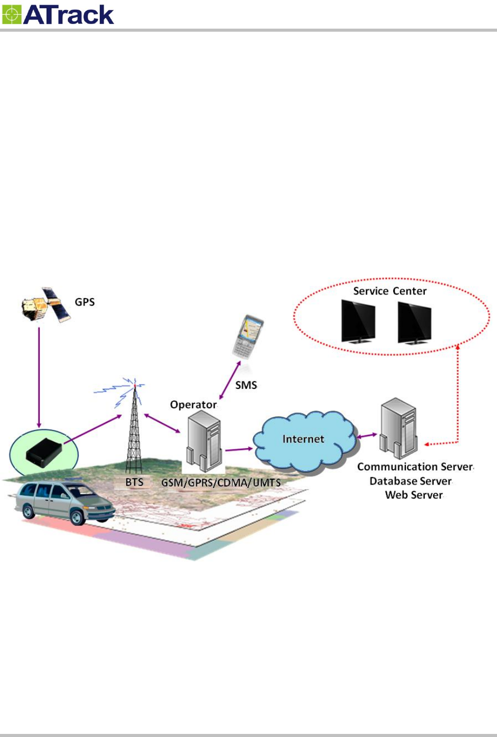
From the following diagram, the AS3/AS3E GPS receiver receives incoming signals from each orbiting
satellite. These signals consist of information such as satellite’s position and the time that the signal was
transmitted by each satellite. The receiver analyzes these data in order to determine how far away each
satellite is and it uses the triangulation method to calculate the vehicle’s exact position. Once the positioning
data along with other event data are gathered, they will be transmitted to the service center across a Mobile
network or via SMS. The communication is bidirectional, which means you can control the AS3/AS3E
remotely across a Mobile network or via SMS.
System Architecture
Confidential Document
Page 5 of 28
3
3.
.
I
In
ns
st
ta
al
ll
la
at
ti
io
on
n
3
3.
.1
1.
.
P
Pa
ac
ck
ka
ag
ge
e
C
Co
on
nt
te
en
nt
t
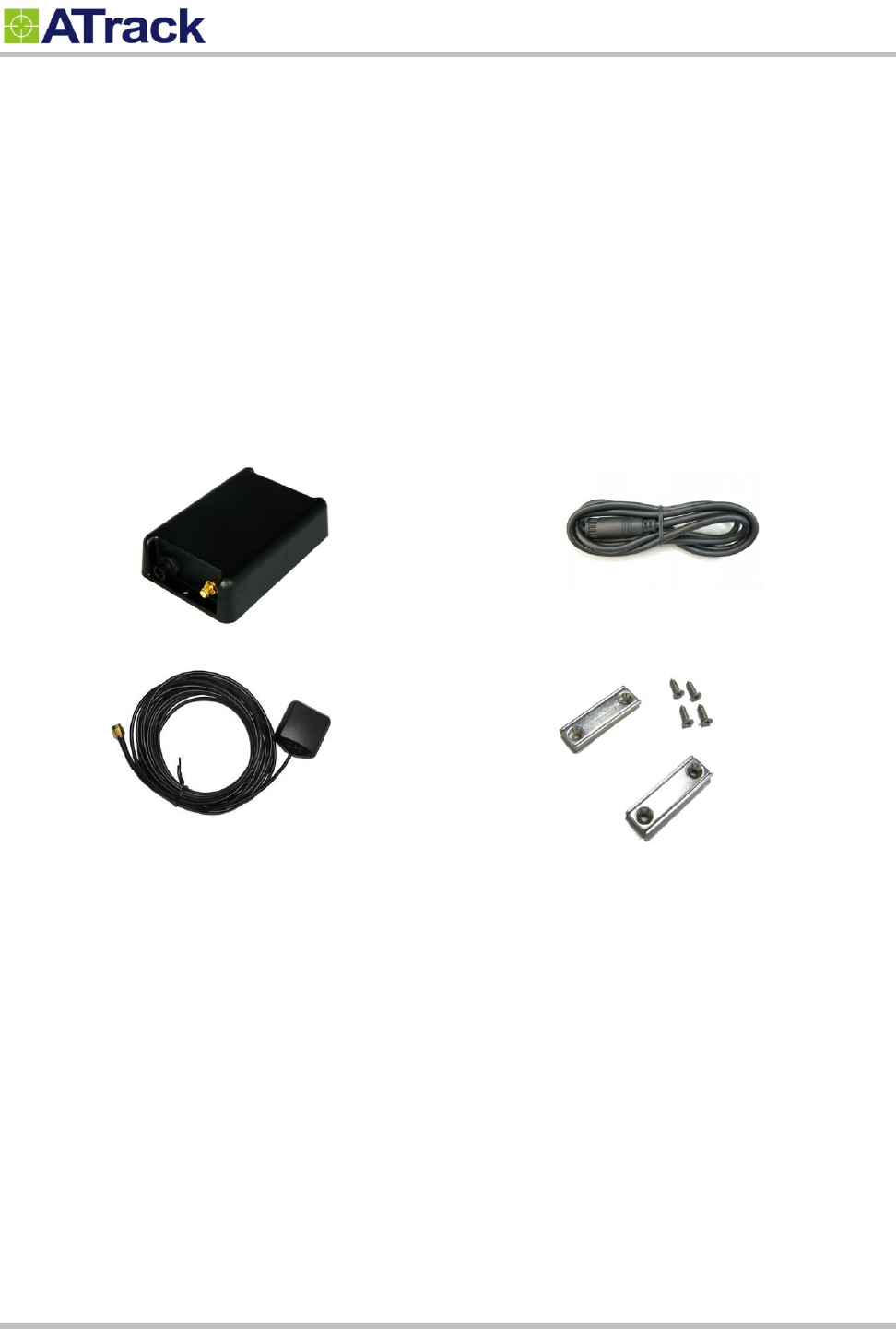
When you open the package, please verify that you received the following device and accessories:
AS3/AS3E Device * 1
GPS Antenna * 1
Power/IO Cable * 1
Magnet Mount Kits (Optional)
Confidential Document
Page 6 of 28
3
3.
.2
2.
.
P
Po
ow
we
er
r
I
I/
/O
O
C
Co
on
nn
ne
ec
ct
to
or
r
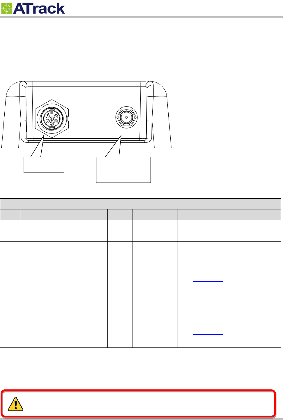
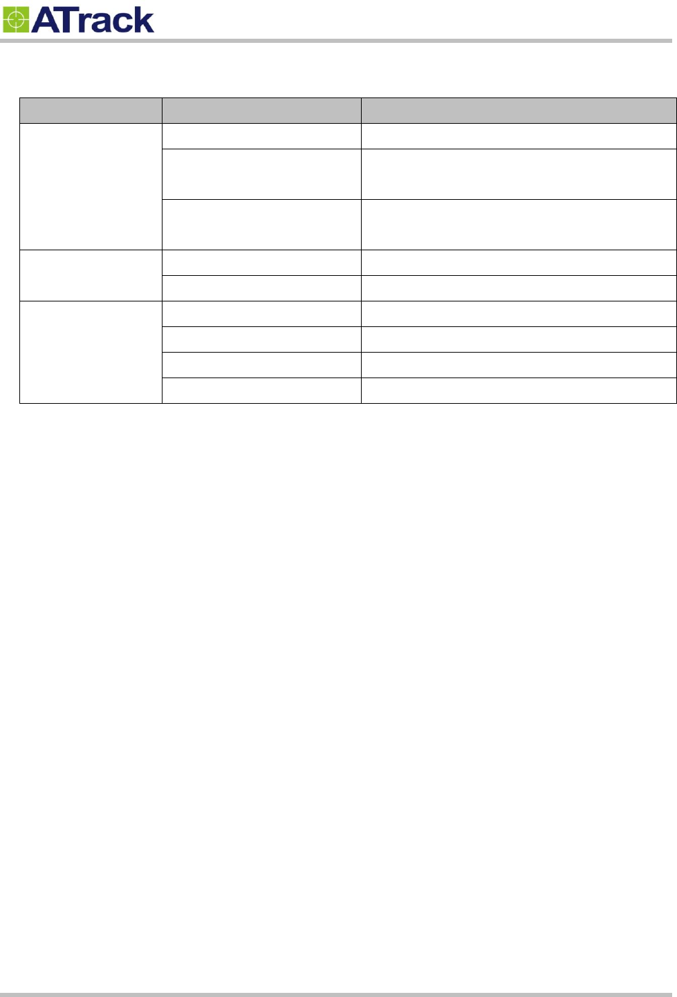
The following figure shows power I/O connector and its pin number.
The following table describes the function of each pin.
Power I/O Connector
Pin#
Function
Color
Designation
Note
1
Main power input
Red
PWR
DC 9V~40V input
2
ACC Input
Yellow
ACC
Ignition status positive trigger input
3**
General Input2 (Default)
Analog Input1
1-Wire Protocol Input *
RS232 Transmit data
Green
IO1
Positive trigger input
Analog input (DC0V~40V)
1-Wire Data input
See Chapter 5.1
4**
General Input1
General Output1 (Default)
Blue
IO2
Negative trigger input
Open collector output (Max.300mA)
5**
General Input3
General Output2 (Default)
RS232 Receive data
White
IO3
Negative trigger input
Open collector output (Max.300mA)
See Chapter 5.1
6
Power ground
Black
GND
* The 1-Wire® Protocol supports up to three 1-Wire™ devices simultaneously, which means you can have
one (iButton® , DS1990A) and two 1-Wire™ temperature sensor probes (DS18B20).
** You may configure the AT$IOCG command to change these specific I/O pins to any of those functions
mentioned as above.
Power I/O
GPS Antenna
(AS3E Only)
Please do not connect a positive voltage to any output pin!
Confidential Document
Page 7 of 28
3
3.
.3
3.
.
I
In
nt
te
er
rn
na
al
l
C
Co
on
nn
ne
ec
ct
to
or
rs
s
a
an
nd
d
L
LE
ED
D
i
in
nd
di
ic
ca
at
to
or
rs
s
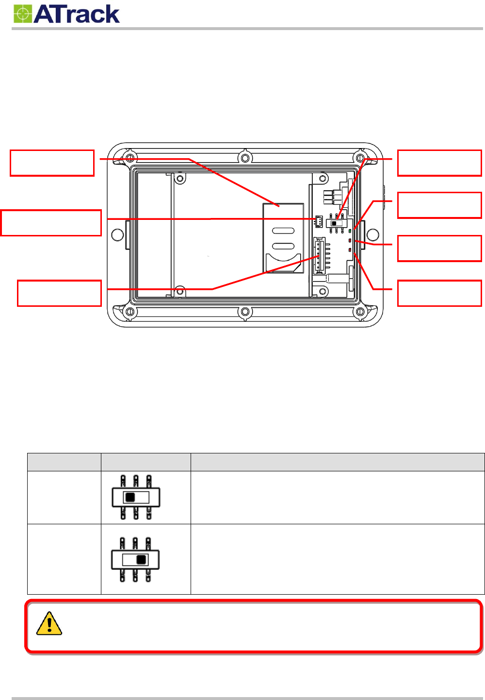
The following figure shows the internal connectors and its functionality.
SIM Socket:
The AS3/AS3E supports a SIM card with either of these two operating voltages: 1.8V (ISO/IEC 7816-3
class C) or 3V (ISO/IEC 7816-3 class B).
RS232 Switch:
The pin#3(Green) and pin#5(White) of power I/O connector can be used for either general I/O or RS232.
The RS232 switch is used for the configuration. See table below for detail description:
Mode
Switch setup
Description
RS232 Mode
Pin#3(Green) and Pin#5(White) are acting as RS232 Tx and Rx.
This is manufactory default mode.
I/O Mode
Pin#3(Green) and Pin#5(White) are acting as general I/Os.
SIM Socket
RS232 Switch
PWR LED
GPS LED
3G LED
Battery connector
I/O Connector
Power off the device and make sure the wire connection before adjust RS232 switch.
Confidential Document
Page 8 of 28
LED Indicators:
LED
Indication
Description
PWR (Green)
Solid On
In full operation mode
1 blink (0.1 sec.) in every 10
sec.
In sleep mode
1 sec. On, 1 sec. Off
GPS module off, External power lost, running on
backup battery
GPS (Red)
0.7 sec. On, 0.7 sec. Off
Searching for GPS signal
Solid On
Position get fixed
3G (Red)
Off
3G module off
0.7 sec. On, 0.7 sec. Off
Searching for 3G signal
0.2 sec. On, 2 sec. Off
Registered on 3G network
Continuous blinking
SIM PIN Error
Note: In the case of SIM PIN Error, the device will check the AT$SPIN every 10 minutes and try to access
the SIM again. The PIN will be validated 3 times and if it fails the last attempt, including the first inserting
time, the SIM card will be locked. Once the SIM is locked, you need to contact your 3G carrier for the
PUK in order to unlock the SIM card using your cell phone.
Confidential Document
Page 9 of 28
3
3.
.4
4.
.
D
DB
B9
9
C
Co
on
nn
ne
ec
ct
to
or
r
W
Wi
ir
ri
in
ng
g
D
Di
ia
ag
gr
ra
am
m
For connecting the device to PC when configuration is needed, the following diagram shows how to
solder/connect the DB9 connector.
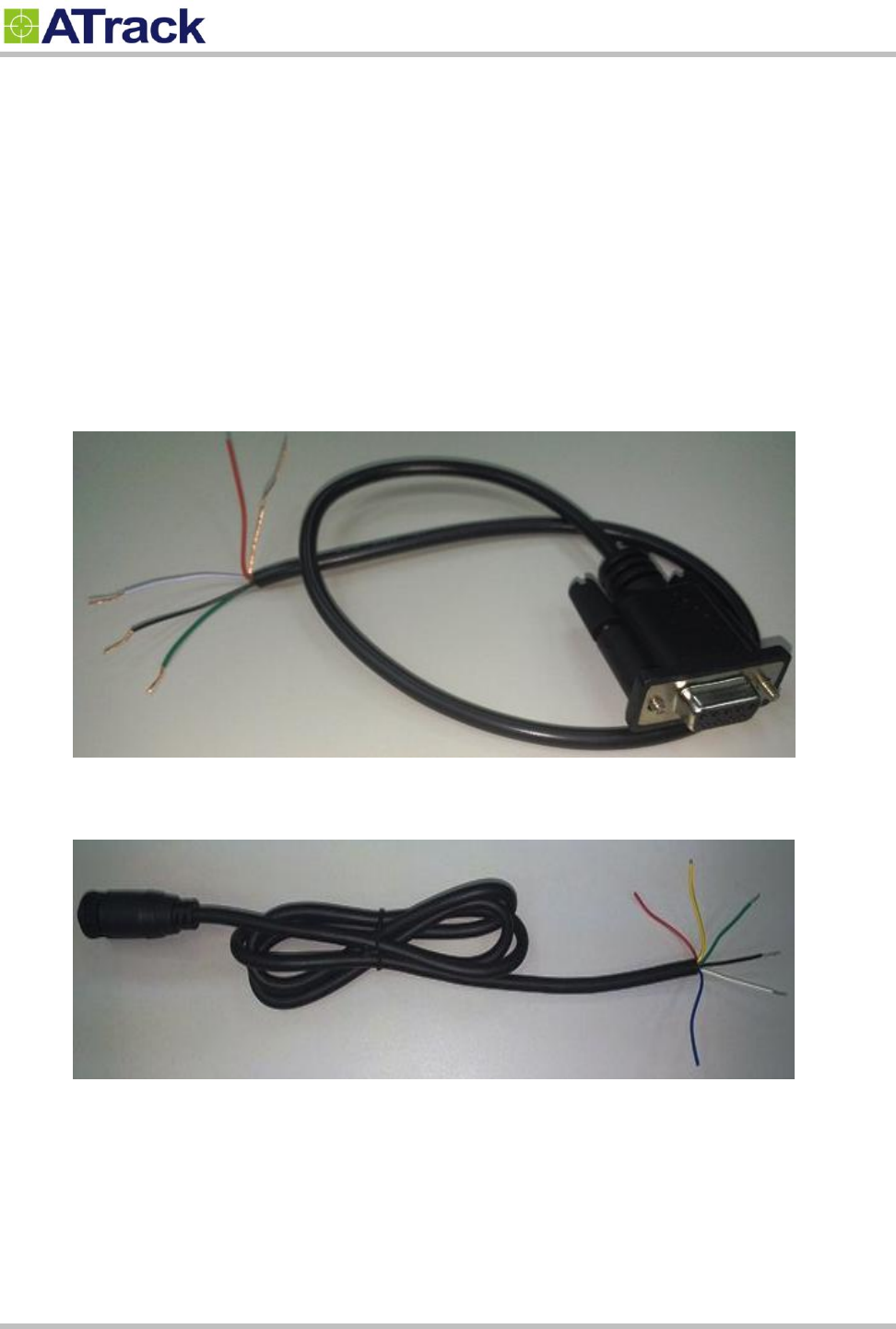
3.4.1. Using ATrack Serial Cable
Material needed: ATrack Serial Cable x 1, AS3 Power I/O cable x 1
1. Cut the ATrack Serial Cable and peel the Green, White, and Black wires as shown:
2. Peel the AS3 Power I/O Cable (Green, White, and Black wires) as shown:
Confidential Document
Page 10 of 28
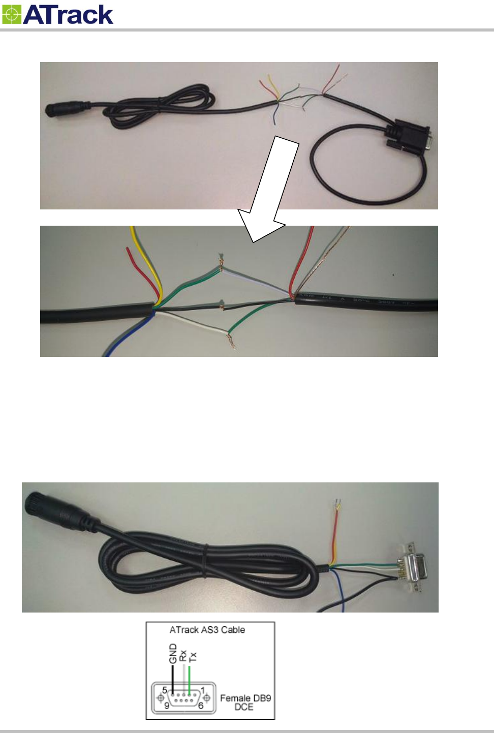
3. Connect two cables together with Green – White, Black – Black, White – Green as shown:
Note: The Ground (Black) wire might need to be connected to the power supply ground as well so
the voltage level is based on the same ground.
3.4.2. Connecting DB9 Female Connector
Material needed: AS3 Power I/O cable x 1, DB9 Female connector x 1
The ping connection is
Green – 2
White – 3
Black – 5

Confidential Document
Page 11 of 28
3
3.
.5
5.
.
G
GP
PS
S
A
An
nt
te
en
nn
na
a
I
In
ns
st
ta
al
ll
la
at
ti
io
on
n
The AS3/AS3E determines its position by communicating with Global Positioning Satellites through an
external GPS antenna. The location where the AS3/AS3E GPS antenna is installed will have great effect in
the overall performance of the GPS receiving. Please note that the following interior conditions may cause
bad GPS reception when a GPS antenna is installed inside interior of vehicle:
Windows with metallic tint
Windshield mounted radio antenna
Windows with solar reflective covers
The MP3 FM transmitter may interfere with GPS reception
Confidential Document
Page 12 of 28
3
3.
.6
6.
.
M
Mo
ou
un
nt
ti
in
ng
g
M
Me
et
th
ho
od
ds
s
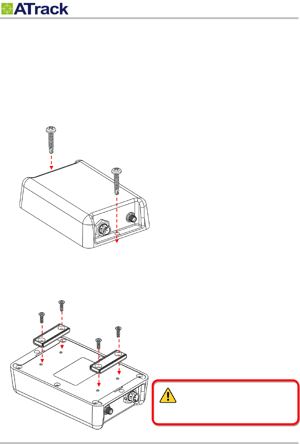
The AS3/AS3E can be either surface or magnet mounted by using appropriate screws.
3.6.1. Surface Screw Mount
Use two #10 screws (diameter=4.8mm) to fix AS3/AS3E on a surface.
3.6.2. Magnet Mount
Use magnet mount kits to install magnets on AS3/AS3E device.
The magnets must be handled with care to
prevent personal injury as they are extremely strong.
Confidential Document
Page 13 of 28
4
4.
.
C
Co
on
nf
fi
ig
gu
ur
ra
at
ti
io
on
n
You may explore great features on the AS3/AS3E either through AT commands or the AK Series Configure
Tool. The commands can be sent to a device via RS232, SMS or Mobile network .
4
4.
.1
1.
.
S
Se
et
t
u
up
p
a
a
D
De
ev
vi
ic
ce
e
U
Us
si
in
ng
g
t
th
he
e
A
AK
K
S
Se
er
ri
ie
es
s
C
Co
on
nf
fi
ig
gu
ur
re
e
T
To
oo
ol
l
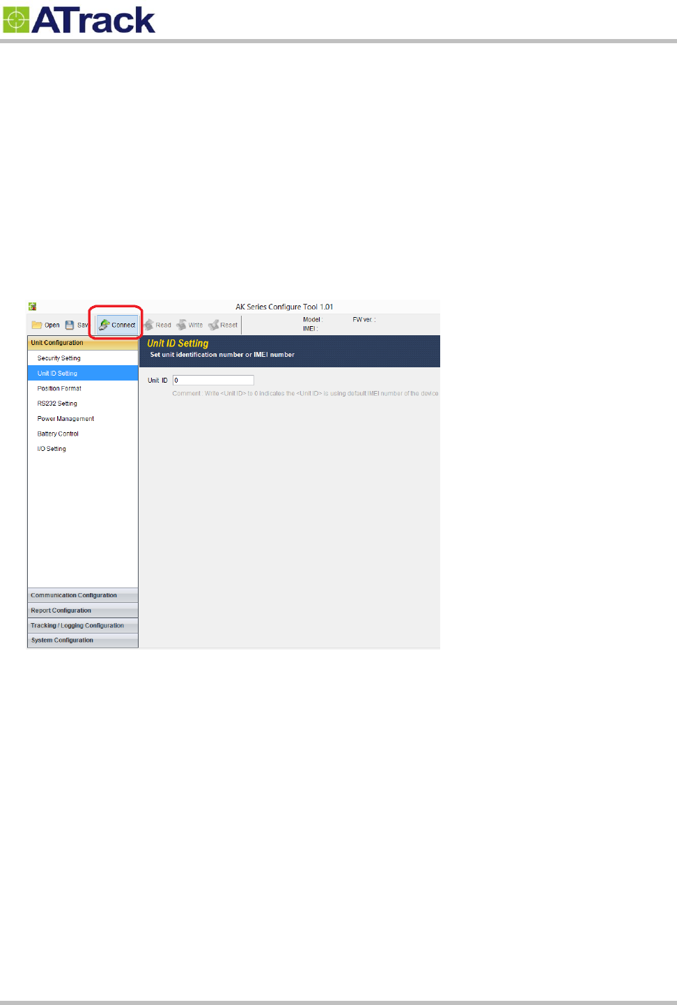
Before running the AK Series Configure Tool, make sure your device is connected to a PC/laptop via RS232.
The AK Series Configure Tool provides a user-friendly intuitive interface that enables you to quickly and easily
set up those basic parameters. Please refer to our AK Series configure Tool user manual for details.
Confidential Document
Page 14 of 28
4
4.
.2
2.
.
C
Co
on
nn
ne
ec
ct
t
a
a
D
De
ev
vi
ic
ce
e
U
Us
si
in
ng
g
H
Hy
yp
pe
er
rT
Te
er
rm
mi
in
na
al
l
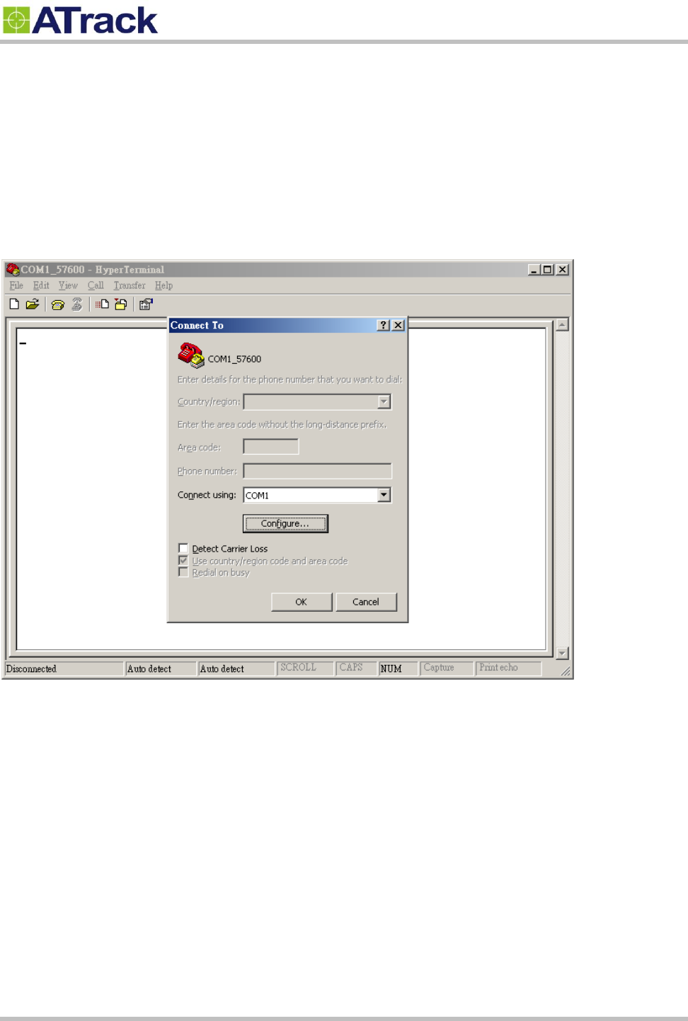
The following example shows how to connect the AS3/AS3E through HyperTerminal. You may use other
popular terminal emulators such as Putty or Tera Term Pro to establish a console session with the AS3/AS3E.
(1) Run HyperTerminal program and choose COM port and click [Configure…] button.
Confidential Document
Page 15 of 28
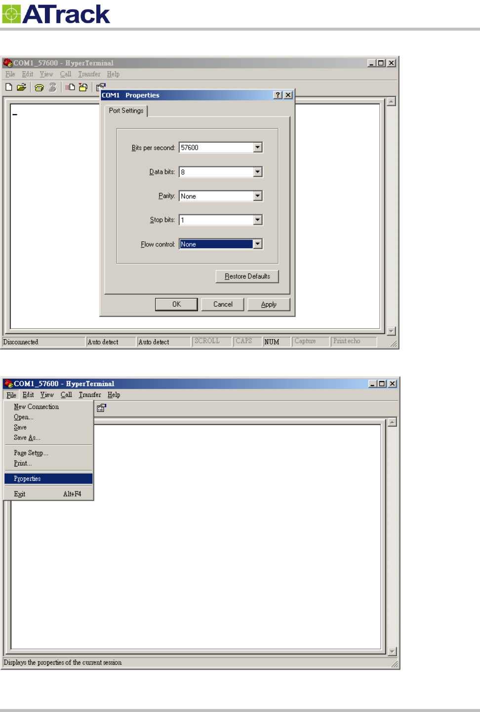
(2) Choose 57600,8,N,1 None flow control properties and click [OK] button.
(3) Click [File][Properties]
Confidential Document
Page 16 of 28
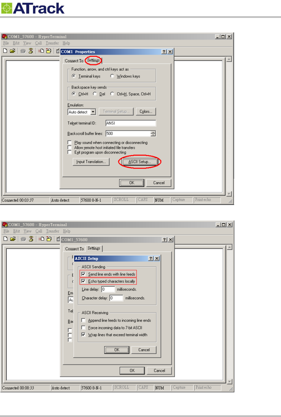
(4) Click [Settings] tab and [ASCII Setup…] button
(5) Checked the following options and click [OK] button
Confidential Document
Page 17 of 28
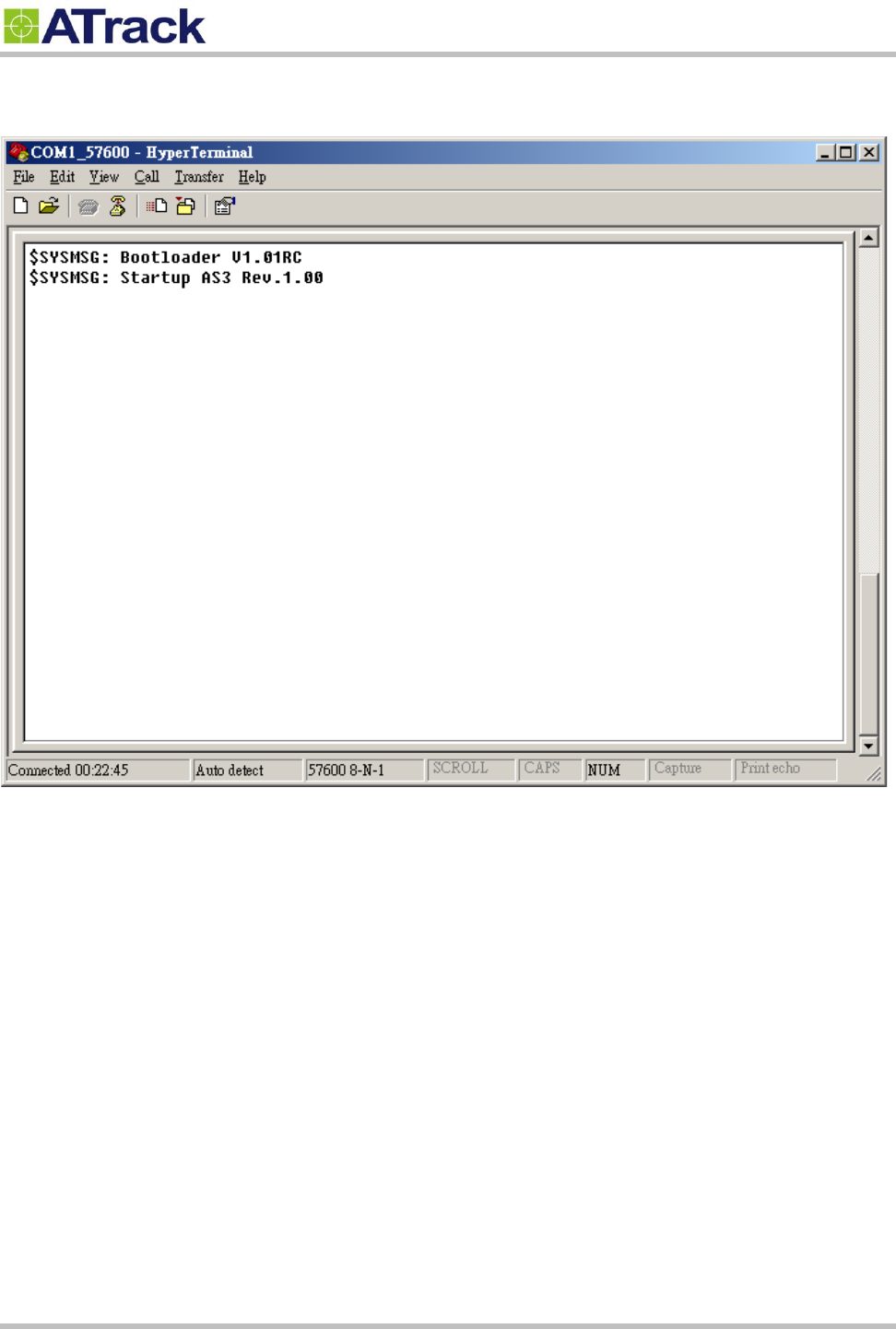
(6) Power ON the device. The startup message will show on the screen. The device AT command can be sent
through the terminal after device startup.
Confidential Document
Page 18 of 28
4
4.
.3
3.
.
C
Co
on
nn
ne
ec
ct
t
a
a
D
De
ev
vi
ic
ce
e
t
to
o
a
a
R
Re
em
mo
ot
te
e
S
Se
er
rv
ve
er
r
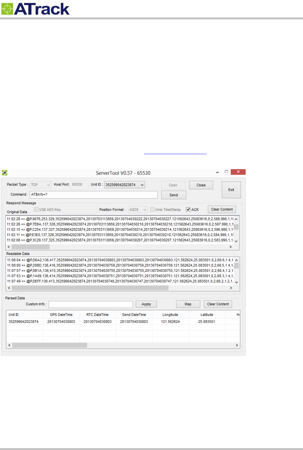
The GPRS or UMTS connection can either be enabled by typing the AT$GPRS command or thorough the AK
Series Configure Tool. Once enabled, the ATrack ServerTool is then installed on a Windows PC in order to
communicate with the AS3/AS3E remotely via a GPRS or UMTS network. The ServerTool is a remote server
application, which is mainly used for parsing data by translating binary formats into readable formats or other
testing purposes. Port forwarding is required if the PC is located behind a Broadband router or any other
firewall device or if it has third-party firewall software installed. The communication is bidirectional, which
means you can issue any AT command to the AS3/AS3E by clicking the Send button. Please refer to the
following snapshot and the Port forwarding website: http://portforward.com/ for details.
Confidential Document
Page 19 of 28
5
5.
.
A
AT
T$
$I
IO
OC
CG
G
C
Co
om
mm
ma
an
nd
d
R
Re
ef
fe
er
re
en
nc
ce
e
5
5.
.1
1.
.
C
Co
on
nf
fi
ig
gu
ur
re
e
o
or
r
Q
Qu
ue
er
ry
y
I
I/
/O
O
P
Pi
in
n
C
Ch
ha
ar
ra
ac
ct
te
er
ri
is
st
ti
ic
cs
s
Command Description
This command is used to set or query the I/O port characteristics of the AS3/AS3E. It is recommended to disconnect all
I/O connections prior to changing the I/O characteristic in order to avoid damage to the I/O port.
Syntax
Write Command
AT$IOCG=<IO1>,<IO2>,<IO3>
Response
$OK
Read Command
AT$IOCG=?
Response
$IOCG=<IO1>,<IO2>,<IO3>
Parameter Description
Parameters
Description
Data Type
Default
<IO1>
I/O configuration on Pin#3 (Green wire)
1: Input2 (VSS ,Pulse counter)
3: Analog Input
4: 1-Wire Data
U8
1
<IO2>
I/O configuration on Pin#4 (Blue wire)
1: Input 1
2: Output 1
U8
2
<IO3>
I/O configuration on Pin#5 (White wire)
1: Input 3 (RPM)
2: Output 2
U8
2
Example
(1) Change all ports to inputs:
AT$IOCG=1,1,1
(2) Change Pin#3 to 1-Wire Data input
AT$IOCG=4,2,2
(3) Change Pin#4 and Pin#5 to digital inputs, and Pin#3 to analog input:
AT$IOCG=3,1,1
Remark
MEMO SERIAL SMS GPRS
Confidential Document
Page 20 of 28
6
6.
.
F
Fi
ir
rm
mw
wa
ar
re
e
U
Up
pg
gr
ra
ad
de
e
The device firmware can be upgraded via RS232 or through the FTP protocol. Following is an example of
firmware upgrade via RS232.
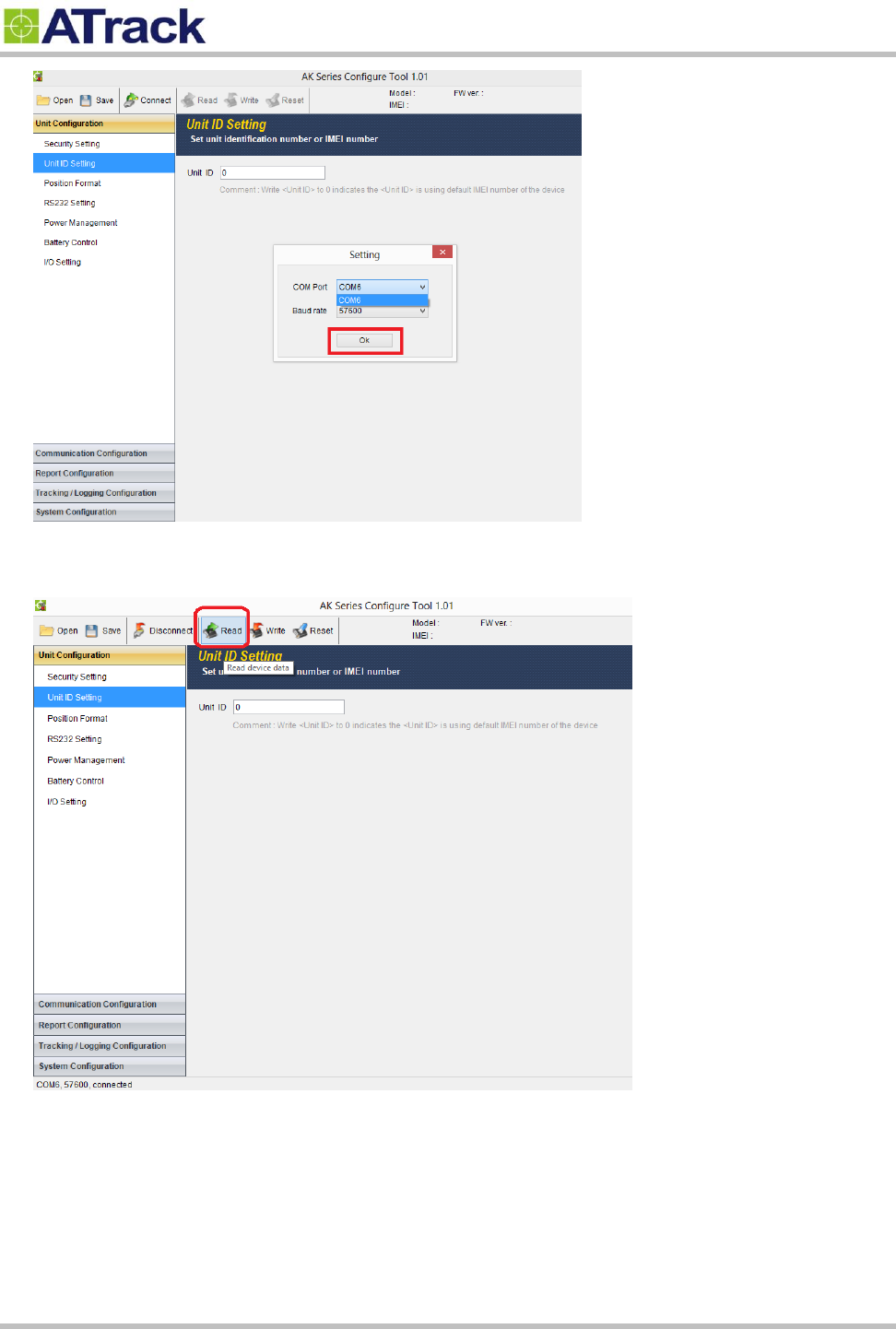
(1) Run the AK Series Configure Tool and click on the [Connect] button.
(2) Select the correct COM port and the Baud Rate (57600) from drop-down lists. Click on the [Ok] button to
close Setting.
Confidential Document
Page 21 of 28
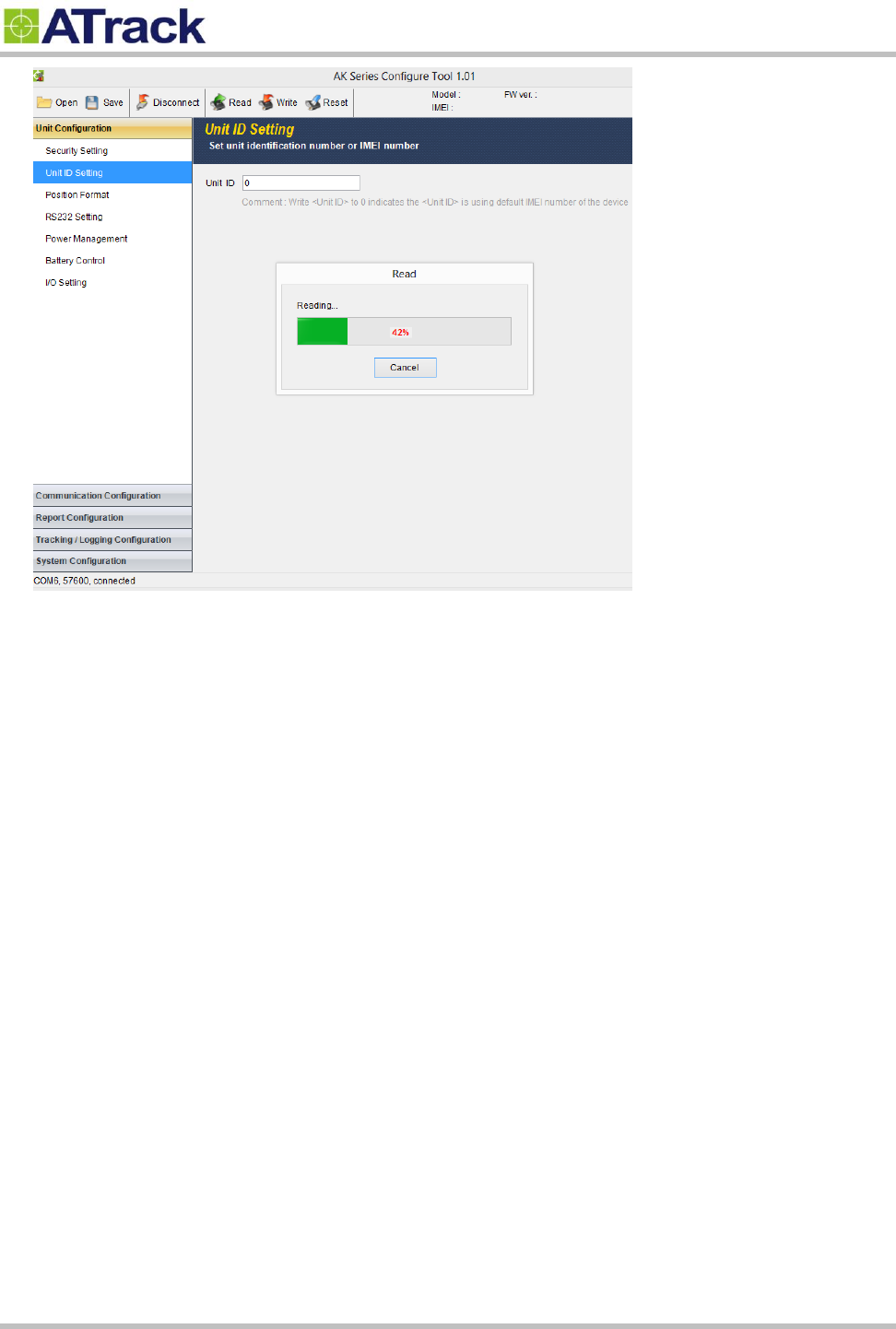
(3) Click on the [Read] button to read out data from the device.
(4) From the following snapshot, the data is being read out.
Confidential Document
Page 22 of 28
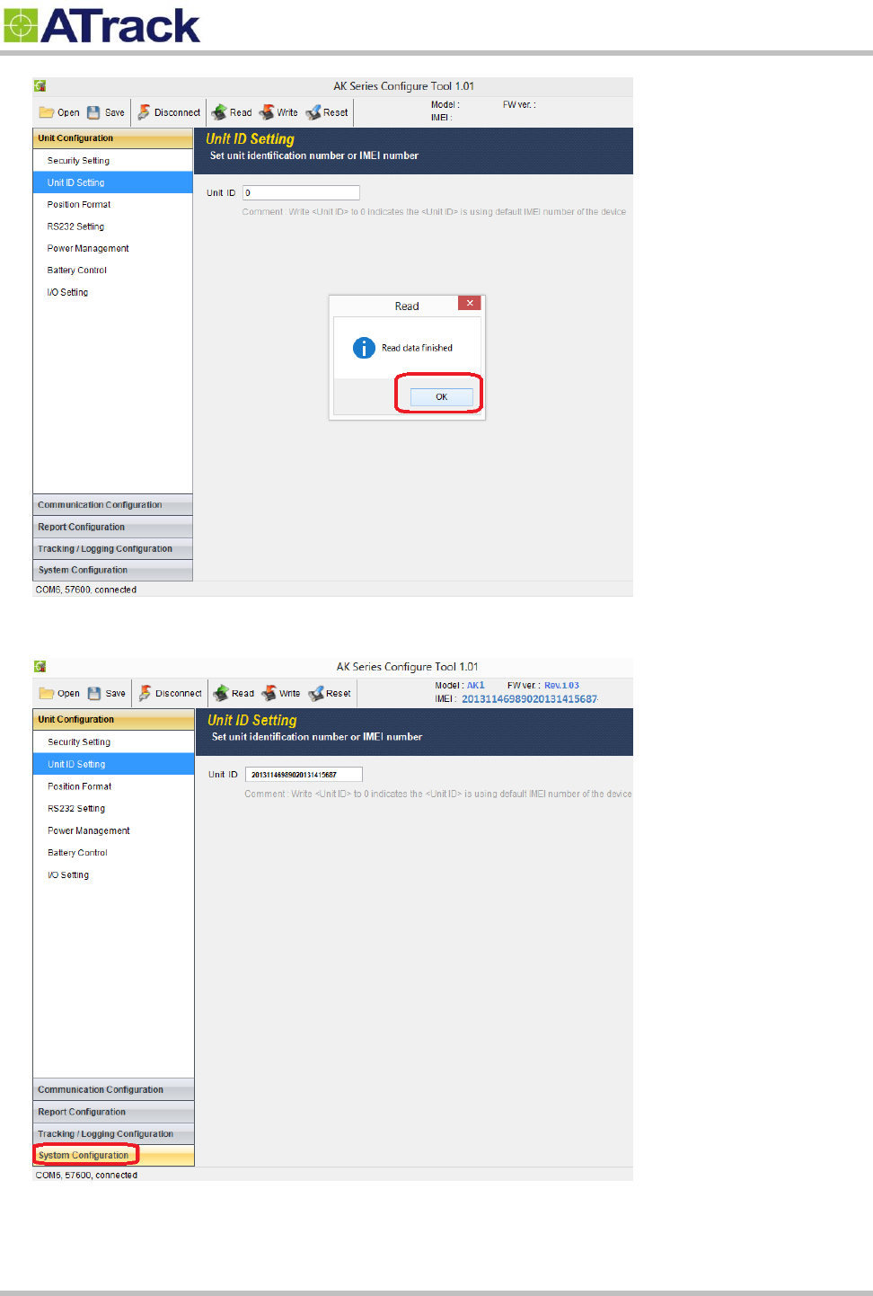
(5) Click on the [OK] button to close the message box.
Confidential Document
Page 23 of 28
(6) Click on [System Configuration]
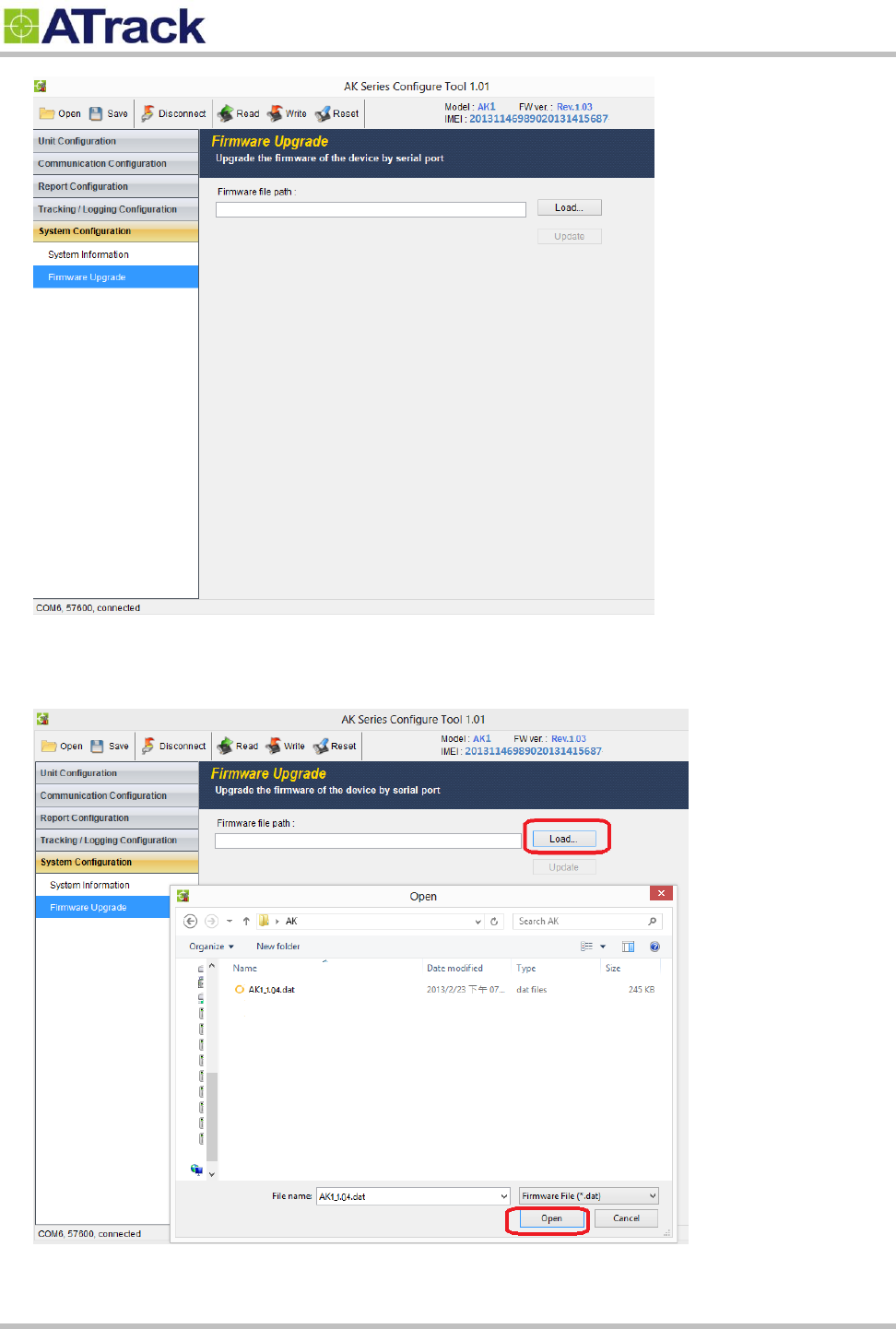
(7) Click on [Firmware Upgrade]
Confidential Document
Page 24 of 28
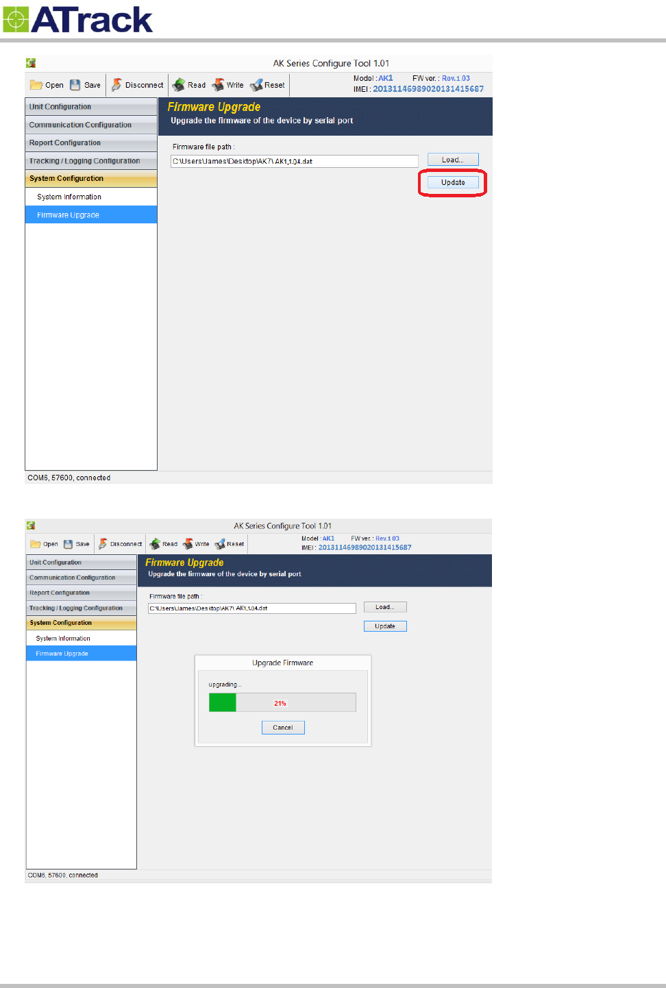
(8) Click on the [Load…] button to browse the firmware file where you saved. In the following example,
AS3/AS3E_1.04.dat is selected and click on the [Open] button to close the window.
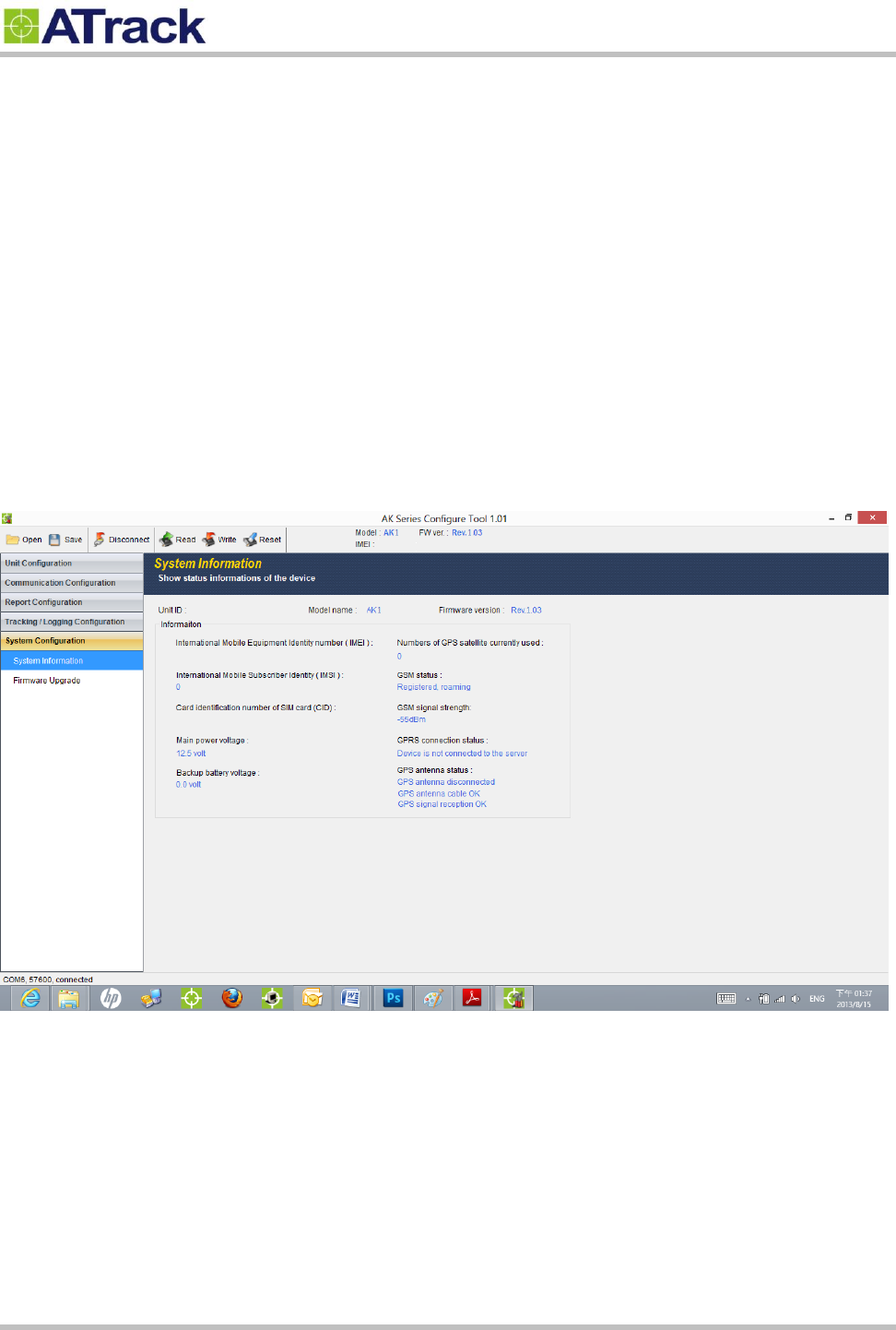
(9) Click on the [Update] button to upgrade the firmware.
Confidential Document
Page 25 of 28
(10) From the following snapshot, the firmware is being uploaded.
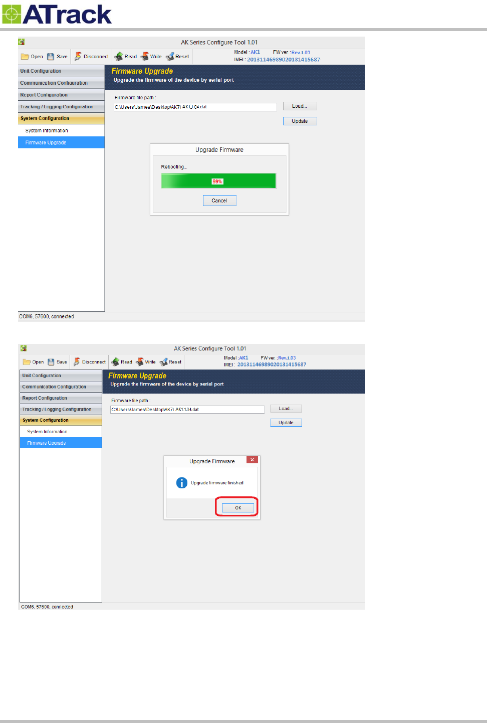
(11) From the following snapshot, the device is being rebooted.
Confidential Document
Page 26 of 28
(12) Click on the [OK] button to close the message box.

Confidential Document
Page 27 of 28
7
7.
.
A
Ap
pp
pe
en
nd
di
ix
x
7
7.
.1
1.
.
H
Ha
ar
rd
dw
wa
ar
re
e
S
Sp
pe
ec
ci
if
fi
ic
ca
at
ti
io
on
n
Model Number
AS3
AS3/AS3E
AS3E
Dimensions (L x W x H)
120 x 80 x 32 mm
Housing
Flame Retardant ABS+PC (UL 94 V-0), IP67 water proof
Operating Temperature
-20℃ ~ +60℃
Electrical Characteristics
Power Supply
8V ~ 36V DC (±20%)
Internal Battery
2050mAh Li-ion rechargeable battery
Cellular Network Communication
Frequency(MHz)
HSPA : Dual-band (850/1900 or 900/2100)
Cellular Antenna
Internal Cellular antenna
SIM Card
1.8V/3V Mini SIM(2FF)
GPS/GLONASS
Receiver
66 Acquisition Channels, L1 Band, C/A Code, -165dBm sensitivity
Accuracy
3.0m CEP50 without SA
Data Acquisition Rate
1Hz
GPS Antenna
Internal GPS antenna
External GPS antenna
GPS Data Buffer
Capacity
2 MB
Accelerometer
3-Axis
Z,X,Y
Resolution
±2g, 10-bits resolution
Interface/Input /Output *The specification shown the max. ports of the I/O configuration.
Input/Output
1 ACC Positive Triggered
*1 Digital Positive, 2 Negative Triggered
*2 Open-Collect Output (Max. sink current 300mA)
*1 Analog input (0~40VDC, 12bits resolution)
*1-Wire Protocol Supported
*1 RS232 interface
Standard Accessories
Power cable
6-wires (1.2m)
GPS Antenna
N/A
GPS Antenna(5.0m)

Confidential Document
Page 28 of 28
7
7.
.2
2.
.
F
FC
CC
C
R
Re
eg
gu
ul
la
at
ti
io
on
ns
s:
:
This device complies with part 15 of the FCC Rules. Operation is subject to the following two
conditions: (1) This device may not cause harmful interference, and (2) this device must accept any
interference received, including interference that may cause undesired operation.
This device has been tested and found to comply with the limits for a Class B digital device, pursuant
to Part 15 of the FCC Rules. These limits are designed to provide reasonable protection against harmful
interference in a residential installation. This equipment generate, uses and can radiated radio
frequency energy and, if not installed and used in accordance with the instructions, may cause harmful
interference to radio communications. However, there is no guarantee that interference will not occur in
a particular installation. If this equipment does cause harmful interference to radio or television reception,
which can be determined by turning the equipment off and on, the user is encouraged to try to correct
the interference by one or more of the following measures:
-Reorient or relocate the receiving antenna.
-Increase the separation between the equipment and receiver.
-Connect the equipment into an outlet on a circuit different from that to which the receiver is connected.
-Consult the dealer or an experienced radio/TV technician for help.
Changes or modifications not expressly approved by the party responsible for compliance could void the
user‘s authority to operate the equipment.
RF Exposure Information
This device meets the government’s requirements for exposure to radio waves.
This device is designed and manufactured not to exceed the emission limits for exposure to radio
frequency (RF) energy set by the Federal Communications Commission of the U.S. Government.
This device complies with FCC radiation exposure limits set forth for an uncontrolled environment. In
order to avoid the possibility of exceeding the FCC radio frequency exposure limits, human proximity to
the antenna shall not be less than 20cm (8 inches) during normal operation.