AUTOLAND SCIENTECH ISCANII-BU Car Diagnostician User Manual
AUTOLAND SCIENTECH Co. LTD Car Diagnostician
User Manual
1
SCANNER FEATURES
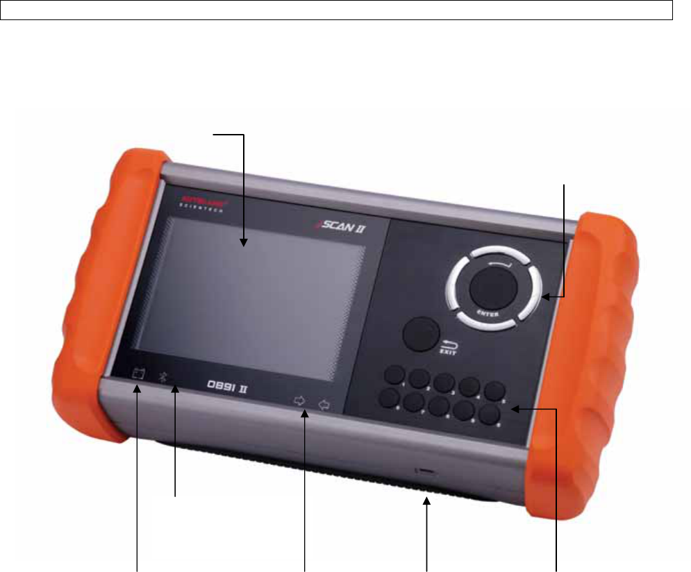
1. FEATURES
Power supply indication light Status light indicator USB socket for Keypad for numbers
for diagnostic circuits software update
Display Screen
Bluetooth Indication
light
Keypad for Directions
2
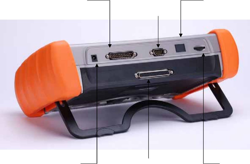
9-Pin Connector
For connection to a PC
or Thermal Printer
25-Pin Connector
For connection with 25-Pin diagnostic adapter/cable.
Interface Specified Connector
The connector for the special interface cards.
9-Pin Connector
Used for attaching optional devices such as a personal computer or the thermal
printer.
Display Screen
Displays data and messages for the user.
Keypad
Used for entering commands and selecting data on the scanner screen.
USB Socket
Download the software from the Internet and program the internal memory. Users
should download the drivers and PS-Module Manager to program the software.
Install the driver before start PS-Module Manager.
Contrast Dial
Used to adjust the brightness for the screen.
Bluetooth Indication Light
The blue light will flash without PC connection. Always ON when connected with
PC.
Ashtray Lighter Power /
Battery Power
Some diagnostic connector does not have power supply or ground. For such
models users have to plug the ashtray lighter power cable or battery power cable
together with the diagnostic cable.
25-Pin Connector
For connection to the
25-Pin Diagnostic Cable
Screen Brightness Dial
Bluetooth Antenna
Ashtray lighter power /
Battery power, DC: 9-16V
Interface specified connector
3
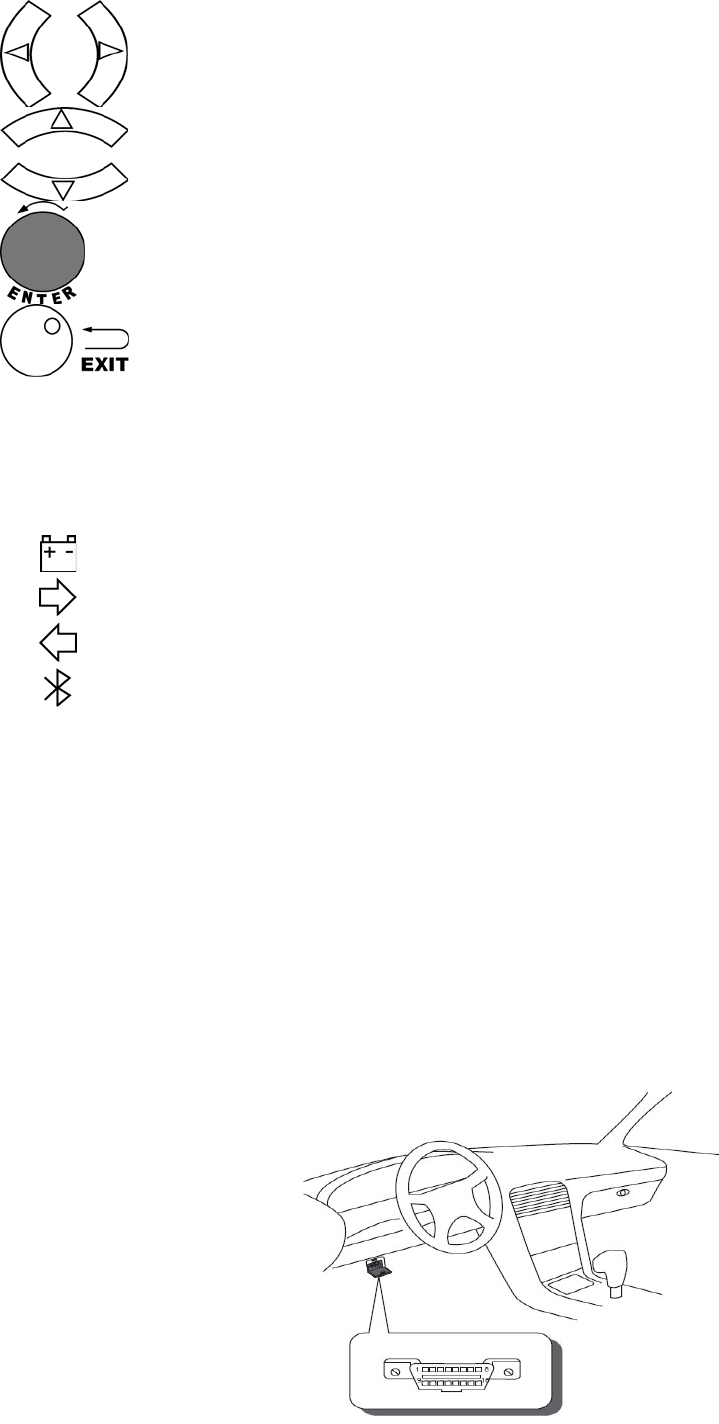
2. KEYPAD
Left and Ri
g
ht arrow ke
y
s: Enables movement throu
g
h dia
g
nostic functions, vehicle
models and systems from the current page to the NEXT or PREVIOUS page.
U
p
and Down arrow ke
y
s: Used for selectin
g
test functions, vehicle models and s
y
stems
that are listed on the CURRENT page.
Enter commands into the scanner.
Interru
p
ts the current
p
rocedure and returns to the
p
revious menu or test mode
selection.
0 ~ 9
Di
g
its 0 throu
g
h 9. Selects the functions, vehicle models or s
y
stems b
y
p
ressin
g
the
numbered keys.
3. INDICATOR LIGHTS
Power Indicator (Red LED light)
Data Link Indicator (Green LED light)
Data Link Indicator (Orange LED light).
Bluetooth Status Indicator (Blue LED light)
If the diagnostic link circuit is shorted to ground or if the control unit is faulty, the green or orange LED light
will turn on steadily when the scanner is connected to the vehicle’s diagnostic connector.
4. QUICK START
(1) FIND THE DIAGNOSTIC CONNECTOR
Most of the connectors are on the driver’s side below the dash board. Sometimes covered by a plastic plate.
Please note that prior to the year 2000 most vehicles were equipped with manufacturer specific connector. Some
manufacturers used different connectors to access different systems. Ex: Toyota. These connectors are located
in the engine compartment. To retrieve manufacturer information, please connect to the appropriate port, failure
to do so will result in a communication error.
4
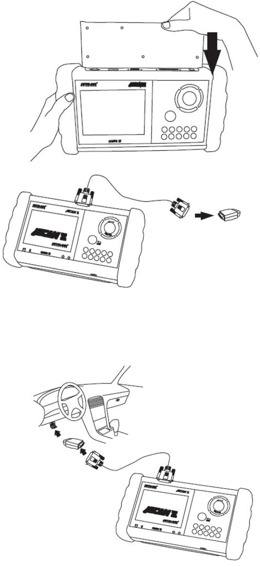
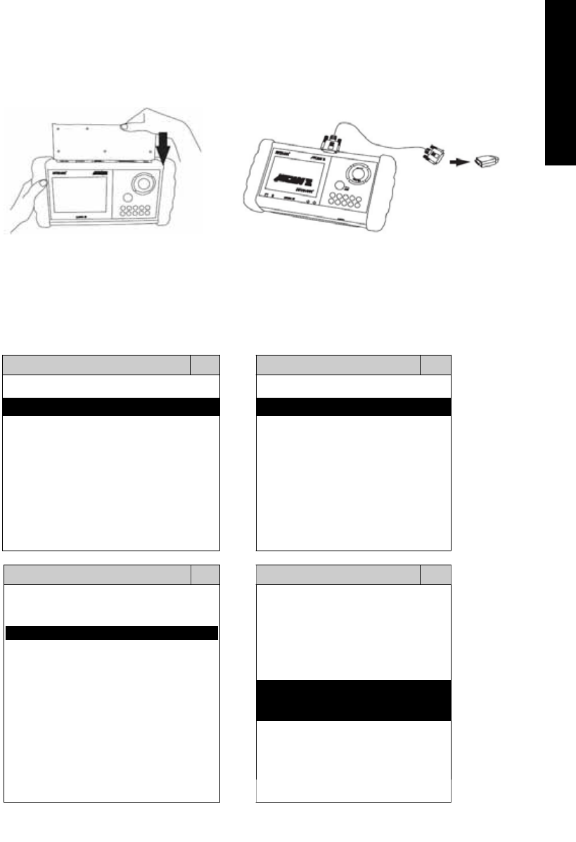
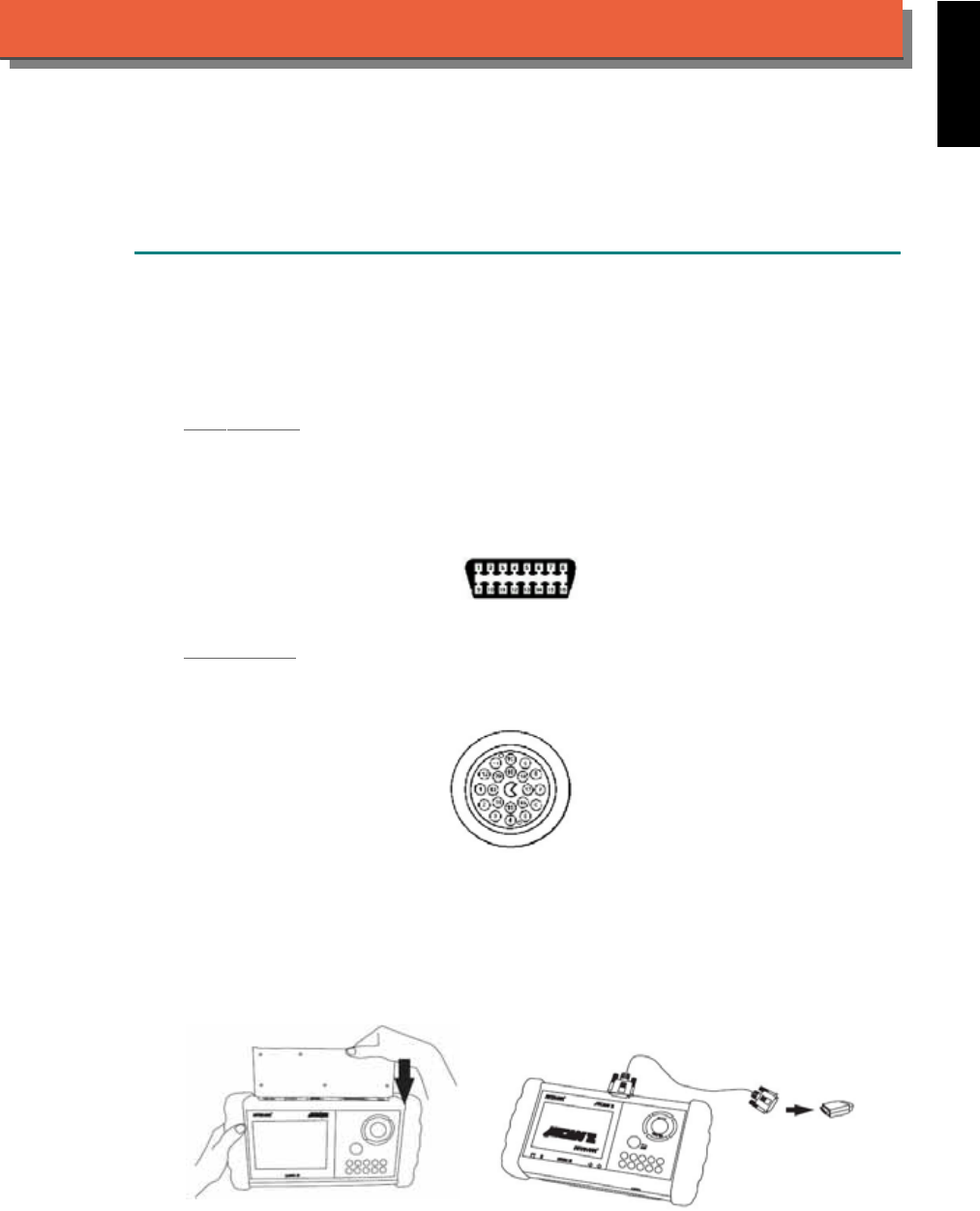
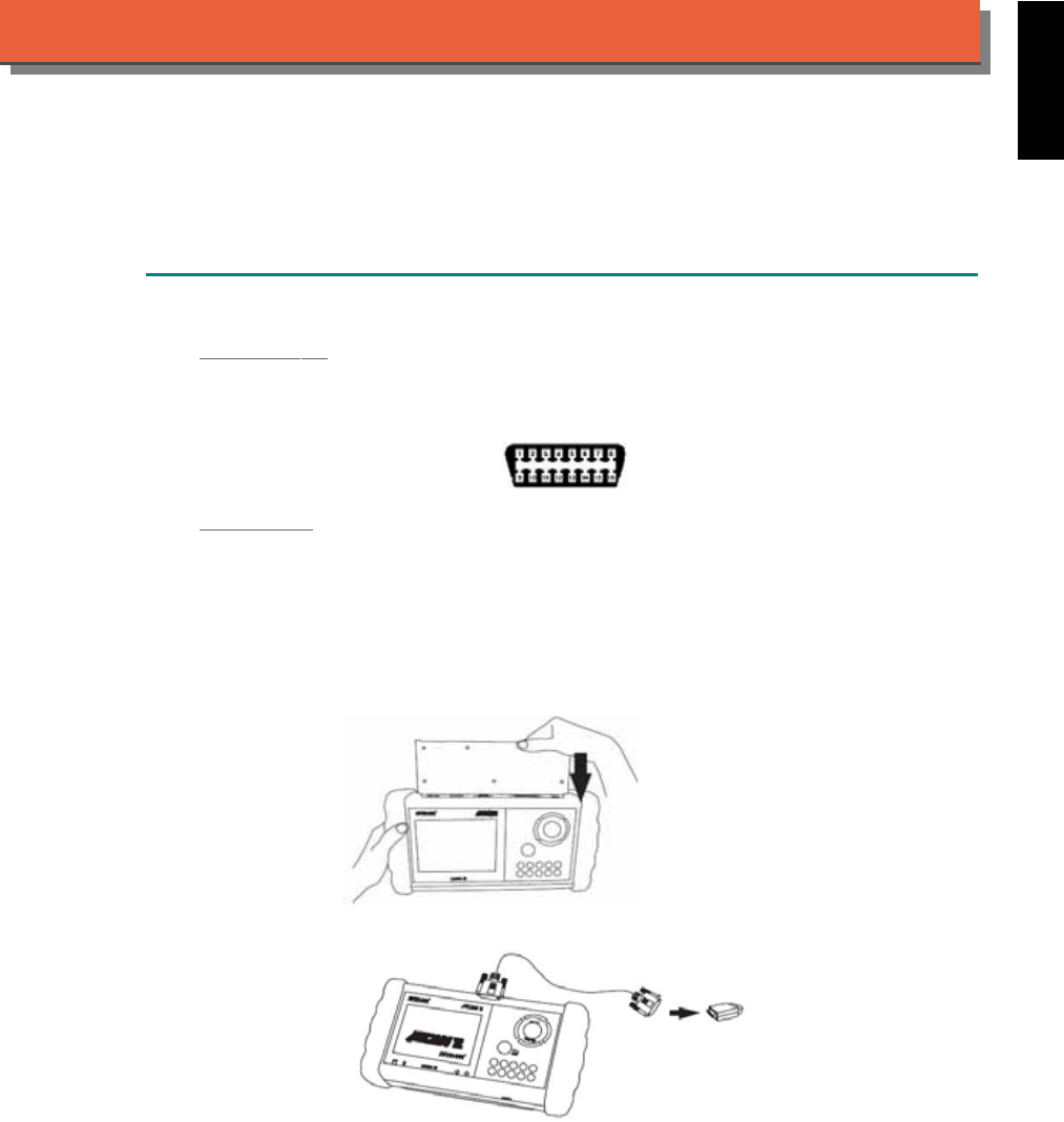
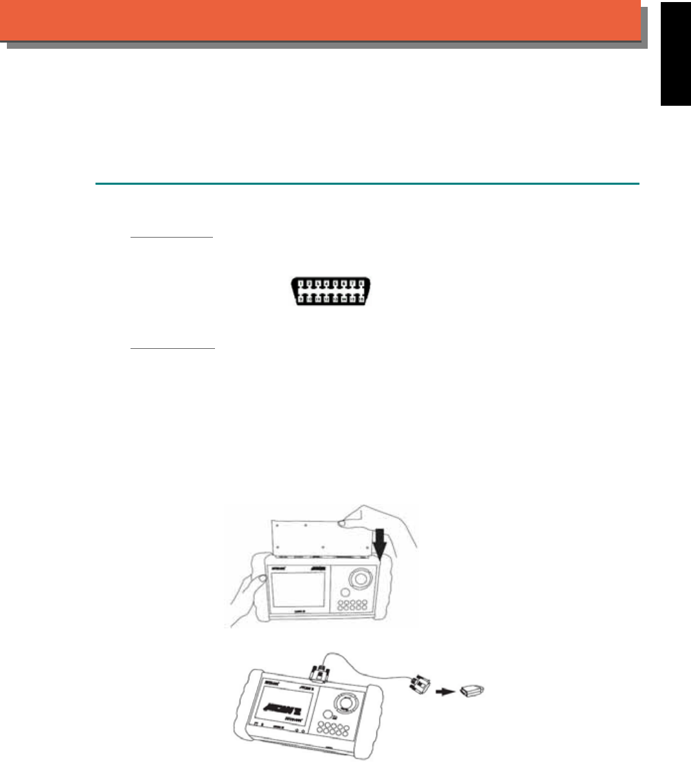
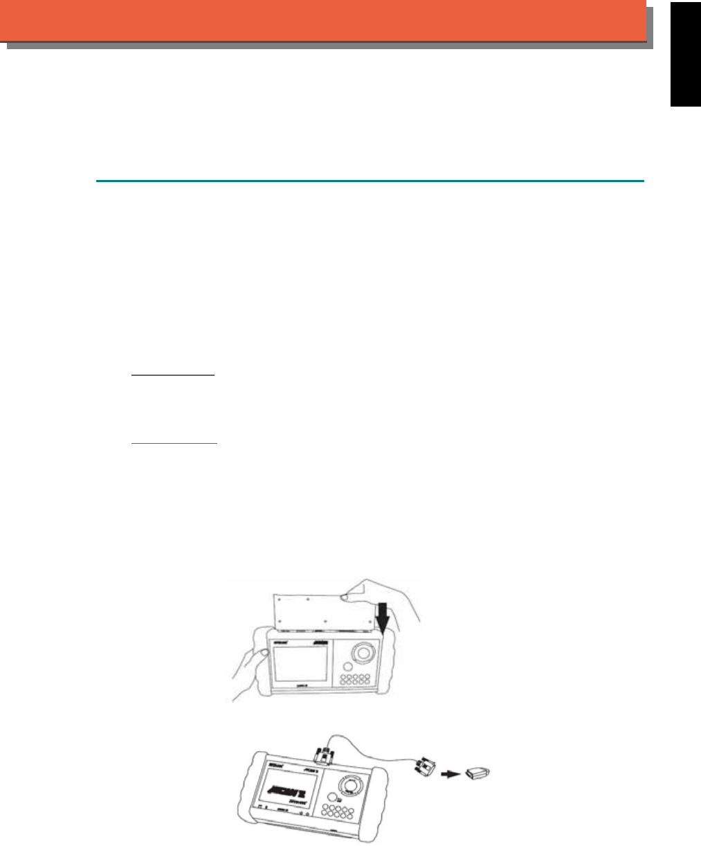
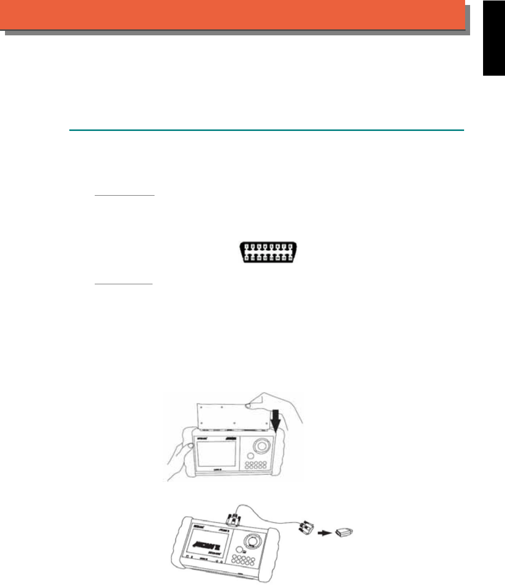
(2) SELECT THE INTERFACE MODULE
There are some interface modules available. For example, OBDII-IM5. Insert the interface module into the base
unit. WARNING! Wrong selection may be harmful for the vehicle or fail to communicate.
(3) CONNECT TO THE VEHICLE
Connect the iSCAN-II and the diagnostic connector in the vehicles. Find the models from the screen of iSCAN-II.
Press ENTER to start the diagnostic function. If the model is not listed on the screen, try to press RIGHT / LEFT
buttons to turn the page.
5
5. ICONS
Along the top or bottom of the display, the following icons may appear which will provide more information
to the user.
DATA STREAM 3/8
Engine Speed 915 rpm
Coolant Temperature 85 ºC
Injection Time 10 ms
Ignition Angle 5 º
Battery Voltage 13.2 V
Electric Load ON
Brake Signal OFF
Page Keys
When either of these icons appears in the top line or bottom line
on the screen, there is more information available. Press the (left),
(right),
(down), and
(up) arrow key to view additional
information.
0..9 Number Keys
1. Press the Number key from 1 to 9 to directly select the vehicle
make or system items.
3/8 Page Information
Displays current page number and total number of pages.
Connecting Failed Faulty Connection Indication
Check and see if the Ignition key is on or if the engine is running.
Check the power requirement for the scanner (10.5 to 14.5 Volts)
Check and make sure that the connection to the vehicle’s
diagnostic connector is secure.
Check for a short circuit in the vehicle’s diagnostic connector.
Check and make sure that the cartridge in use supports this
vehicle’s system.
Check to make sure that you have selected the correct cables.

iSCAN-
II
Documentation
ACURA
®
HONDA
®
DIAGNOSTIC SYSTEM
GETTING STARTED
1. FIND THE DIAGNOSTIC SOCKET
There are two kinds of diagnostic sockets for ACURA / HONDA diagnostic system. Prior to the
year 1998, most vehicles were equipped with 3-Pin socket.
OBD- II Socket
Most OBD-II diagnostic sockets are located under the steering wheel on driver side. The rest of
sockets may be located under the glove compartment on passenger side or close to the side
kicker on driver's. Please refer to the sticker direction under the dashboard on driver side and
near the steering column. The socket may locate at the following position.
The diagnostic socket is located under the dashboard on driver side, near the left side of the
steering column. For example ACCORD (’98-03), CIVIC (’96-00), PASSPORT (96-99).
The diagnostic socket is located in the central console. It is under the ashtray. (Remove the
ashtray). For example, ACCORD (‘95-97).
The vehicle’s diagnostic socket is located under the glove compartment. For example, S2000
(00-03), Pilot (‘03)
The vehicle’s diagnostic socket is located on the right side of the central console, near the
passenger’s glove compartment. For example, DEL SOL, CR-X (’96-97), ODYSSEY (’96-98),
PRELUDE, CR-V (‘97-01), INSIGHT (’00-02). Note: To connect PRELUDE (’97-01), remove the
trim panel.
The diagnostic socket is located under the armrest. To connect, remove the beverage holder.
For example, PRELUDE (‘96).
The diagnostic socket is located under the dashboard on driver side , near the right side of the
steering column. For example, CIVIC (’01-03), ODYSSEY (’99-03), CR-V (‘02-03)
3-PIN Soc ket
For the older models which were not equipped with OBD-II socket, there is a 3-PIN socket
available. Please refer to the sticker direction under the dashboard on driver side and near the
steering column.
The diagnostic socket is located under the glove compartment on passenger side. It is very
close to side kicker. For example, CIVIC, CR-X (‘92-95), DEL SOL (‘93-95)
The diagnostic socket is located in the central console. It is above the ashtray or coin tray. For
example, PRELUDE (‘92-95).
The diagnostic socket is located in the central console. It is under the ashtray or coin tray. For
example, PASSPORT (‘94-95/5)
The diagnostic socket is located under the glove compartment on passenger side. It is near the
side kicker. For example, ACCORD (‘94-95 L4)
The diagnostic socket is located under the glove compartment. For example, ODYSSEY (’95).
iSCAN-II for ACURA / HONDA © 2008 Autoland Scientech. Page 1
AUT
LAND
®
SCIENTECH
ACURA / HONDA
2. SELECT THE INTERFACE MODULE
There is only one interface module available for ACURA / HONDA diagnostic system, OBDII-
IM5. Insert the interface module into the base unit firmly. Select the adapter that corresponds to
the socket, ex. OBDII-AC-16P.
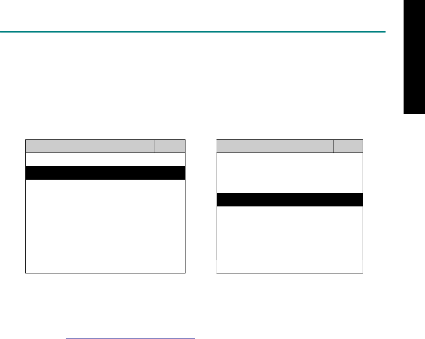
3. CONNECT TO THE VEHICLE
Plug the available diagnostic adapter into the diagnostic socket in the vehicle. Select the
ACURA / HONDA from the screen of iSCAN-II. Press ENTER to start the diagnostic function. If
the model is not listed on the screen, try to press RIGHT / LEFT buttons to turn the page.
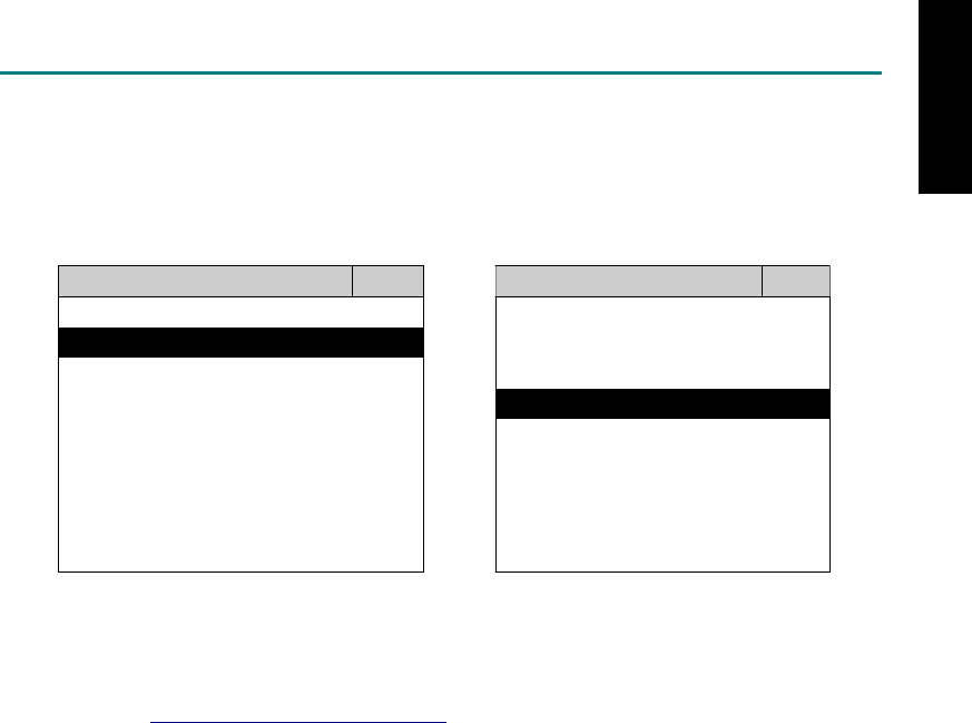
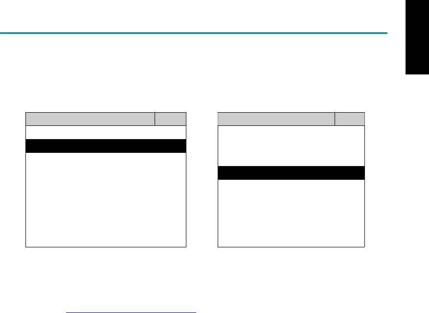
MAIN MENU
Vehicle Diagnostic
1 Vehicle Diagnostic 1 <ASIAN>
2 IMS
2
(Interface Module 2 <EUROPEAN>
Simulation System)
3 Component Test System
10 OBDII Standard Compliant
iSCAN-II (V1.00)
20 SETUP
<ASIAN>
<JAPAN>
1 <KOREA>
2 <JAPAN>
1 DAIHATSU NON-CAN
iSCAN-II (V1.00)
3 CHRYSLER
iSCAN-II (V1.00)
4 FORD OEM(OBDII 95~)
2 DAIHATSU CAN
iSCAN-II (V1.00)
3
HONDA
MAZDA OEM(OBDII 01~)
iSCAN-II (V1.00)
5. GM US
iSCAN-II (V1.00)
4 ACURA
iSCAN-II (V1.00)
iSCAN-II (V1.00) 5 ISUZU
iSCAN-II (V1.00)
The figure is for reference only. Autoland Scientech updates the software very often. The
screen shown may not be the same as the newest software delivered.
iSCAN-II for ACURA / HONDA © 2008 Autoland Scientech. Page 2
ACURA / HONDA
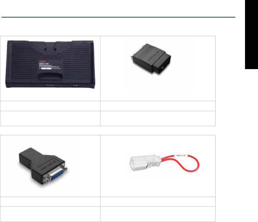
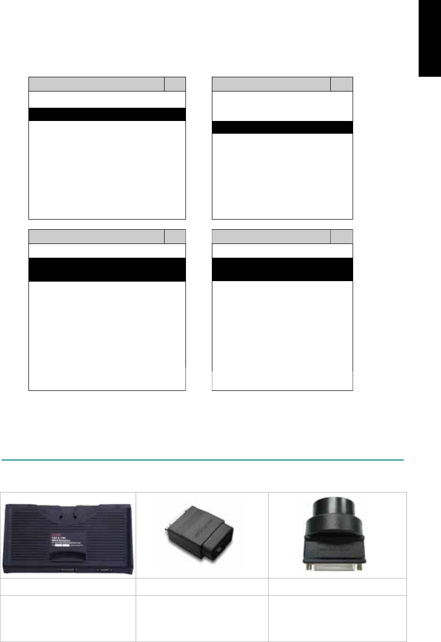
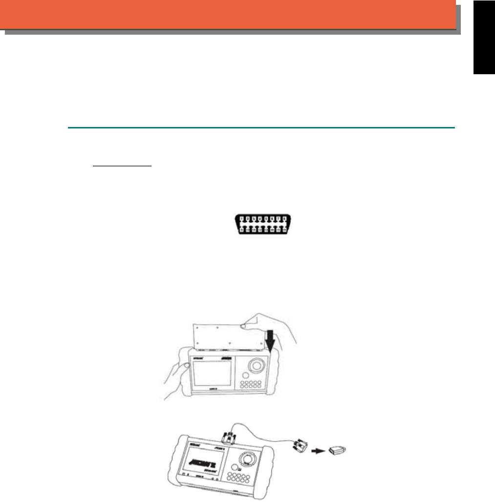
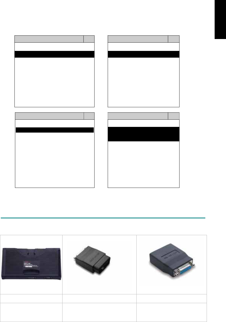
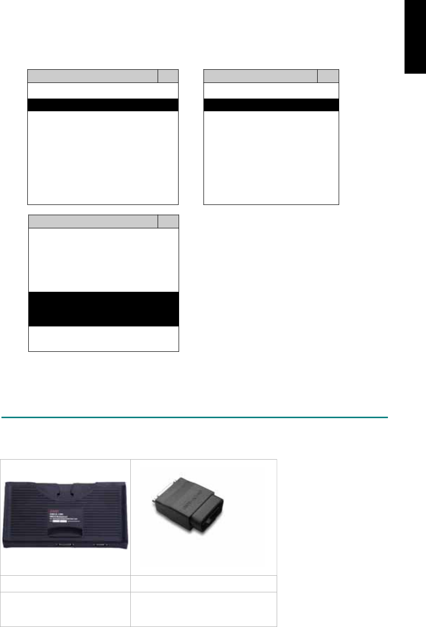
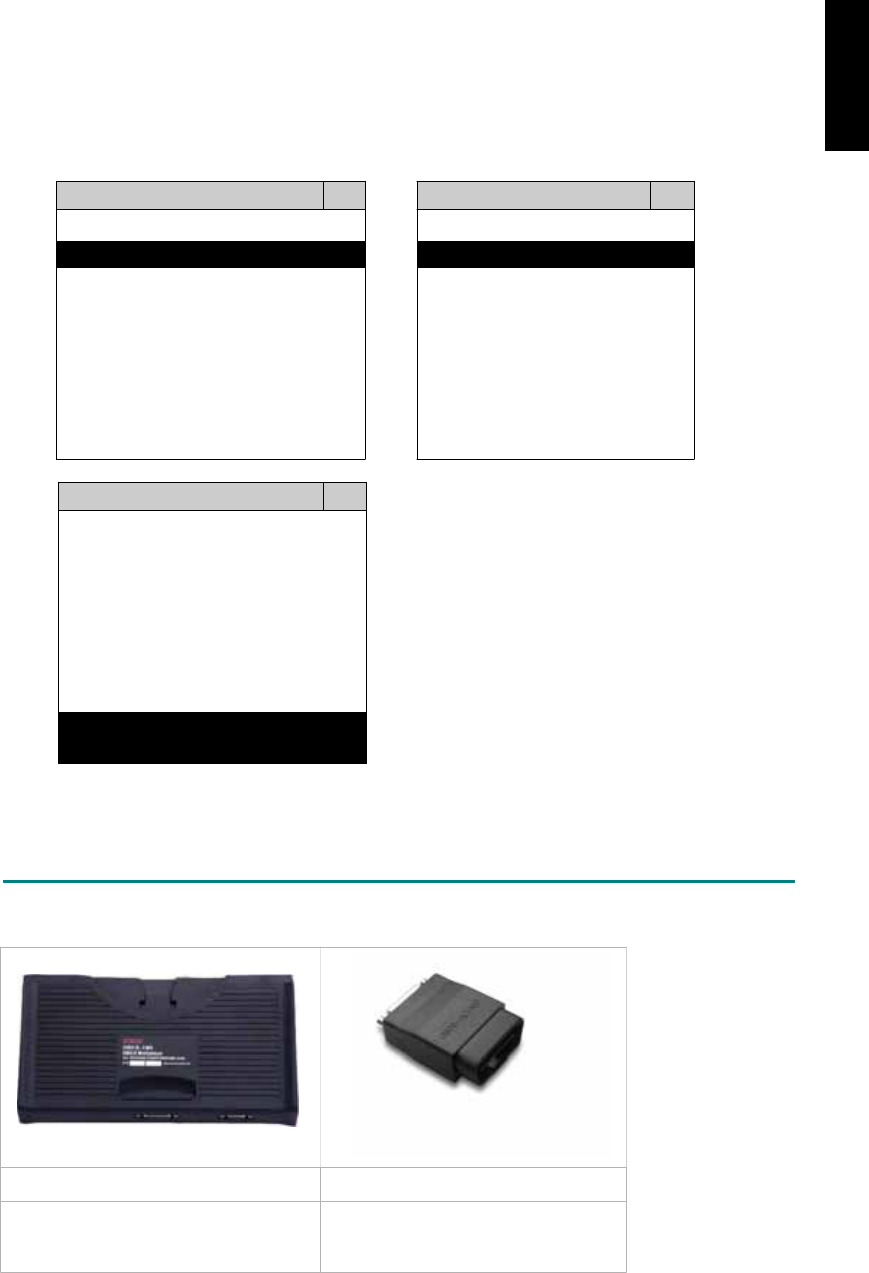
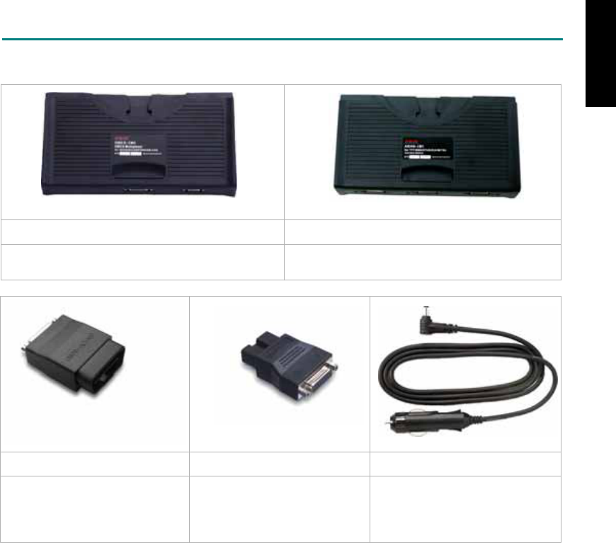
ADAPTERS AND INTERFACE MODULE
There is only one interface module available for the diagnostic system, OBDII-IM5.
OBD
II
-IM5 OBD
II
-AC-16P
OBD-II Full Specification Multiplexer The most common adapter for the new models.
Connect to the OBDII-IM5 with AC-EC1.
HND-AC-3P HND-C-2P
The adapter for the old models. The adapter to trigger the self-test light at the
instrument cluster.
There are some adapters available. Refer to the “Diagnostic Cable Connection Quick Manual” for more
detailed connection / wiring information.
iSCAN-II for ACURA / HONDA © 2008 Autoland Scientech. Page 3
ACURA / HONDA
START TO DIAGNOSE
ACURA and HONDA vehicles are equipped with the same diagnostic systems. Select ACURA or
HONDA may have the same functions for the diagnostic system.
Select ACURA or HONDA by pressing the ENTER button. Turn ignition ON or make engine running at
idle. WARNING! Ignition ON without engine running may have a flat battery.
Select the system from the screen. There may be many systems on the vehicle, try to press RIGHT
button to turn the page. If the ECU response is successful, the screen will show all the available
functions.
ACURA ENGINE
1 ENGINE 1 ID CODES
2 A/T 2 READ FAULT CODE
3 ABS / VST
4 SRS
5 EPS
3 CLEAR FAULT CODE
4 DATA STREAM
5 CLEAR ADAPTATION
6 2-PIN CODE LOOKUP 6 ECU RESET
The figure is for reference only. Autoland Scientech updates the software very often. The screen
shown may not be the same as the newest software delivered.
Autoland Scientech will keep updating the diagnostic software for ACURA / HONDA. Please refer to
the software specification.
Visit our website, http://www.autolandscientech.com , and apply for membership. You will get E-paper
every month and find more diagnostic technical information.
iSCAN-II for ACURA / HONDA © 2008 Autoland Scientech. Page 4
ACURA / HONDA

TROUBLE SHOOTING
iSCAN-
II
never shows anything on LCD screen and there's no back-light?
1. Please check the cable and the connector again.
2. The voltage of the battery should be higher than 10V.
3. Check the power from OBD-II connector. PIN-16 is power, PIN-4 or PIN-5 is ground.
4. Check fuses in BU-EC (25-Pin Base Unit Extension Cable).
iSCAN-
II
never shows anything on LCD screen and the back-light is ON?
1. Check the diagnostic software using iSCAN-II/PSModule3 File Manager from PC. The
software for iSCAN-II may be missing or broken.
2. Adjust the brightness dial for the LCD panel. The brightness may be too dark.
Can't find the system on the screen?
1. Press Right button for more systems. There are too many systems which can't be shown
on the same page.
2. The diagnostic software does not have this system. Please refer to the specification. We
apologize for the inconvenience.
The green or yellow LED flashed on for a while, then showed 'CONNECTION FAILED'
on the LCD screen?
1. Make sure the ignition is ON or make the engine running at idle.
2. Ignition OFF for a while, then Ignition ON and try again.
3. Check the cable and the adapter. Unplug all cables and adapters and plug-in again.
4. Make sure the vehicle equips with the correct system. For example, the manual
transmission will not have A/T transmission ECU.
5. The vehicle will NOT equip with all the systems listed on the software. Some special
systems are only available on the luxury models.
6. The ECU is malfunction or the diagnostic line from the ECU is open or short to the ground or
power.
7. Battery voltage is too low.
Successfully connected to the system but shows 'VERSION UNKNOWN' on the LCD
screen?
Due to the prompt development of the Motor manufactures, the diagnostic software might not
be able to communicate with all ECU versions. Download the newest software from the member
area of Autoland Scientech website and try again. (http://www.autolandscientech.com)
If the same situation occurs, please report the information of ID pages to our local distributors.
We will keep updating the diagnostic software for new ECUs. Please excuse any inconvenience
this may cause.
Successfully connects to the system but shows 'LINK FAILURE' on the title?
Some ECUs are not as stable as our research department expected. Please report the
information of ID pages to our local distributors. Our R/D department will do our best to fix the
problems as soon as possible. Please excuse any inconvenience this may cause.
Document Version 1.00 for iSCAN-II, © 2008 Autoland Scientech
The information contained herein is the exclusive property of Autoland Scientech
®
and shall not be distributed, reproduced, or disclosed
in whole or in part without prior written permission of Autoland Scientech
®
. Autoland Scientech
®
reserve the right to make any change
without notice. The trademarks mentioned belong to the owners.
iSCAN-II for ACURA / HONDA © 2008 Autoland Scientech. Page 5
ACURA / HONDA
iSCAN-
II
Documentation
BMW
®
DIAGNOSTIC SYSTEM
GETTING STARTED
1. FIND THE DIAGNOSTIC SOCKET
There are two kinds of diagnostic sockets for BMW diagnostic system. From 1987 to 2000, the
models were equipped with round type 20-Pin diagnostic socket. The models since 2001 have
been equipped with OBD-II socket.
OBD- II Socket
For the newer models, ex. E65, E60, E90...etc, OBD-II diagnostic socket can be found under a
plastic cover of dashboard on driver side. It is very close to side kicker and near the door. US
models from 1995 to 2000 were equipped with both 20-Pin and OBD-II diagnostic sockets. Only
20-PIN diagnostic socket can work in the diagnostic communication. OBD-II diagnostic socket is
for Generic OBD-II communication purpose only.
OBD-II socket
20-PIN Socket
The oldest models equipped with 20-PIN socket. The socket is covered by a plastic cover and
under the engine hood, beside the absorber strut tower.
20-PIN socket
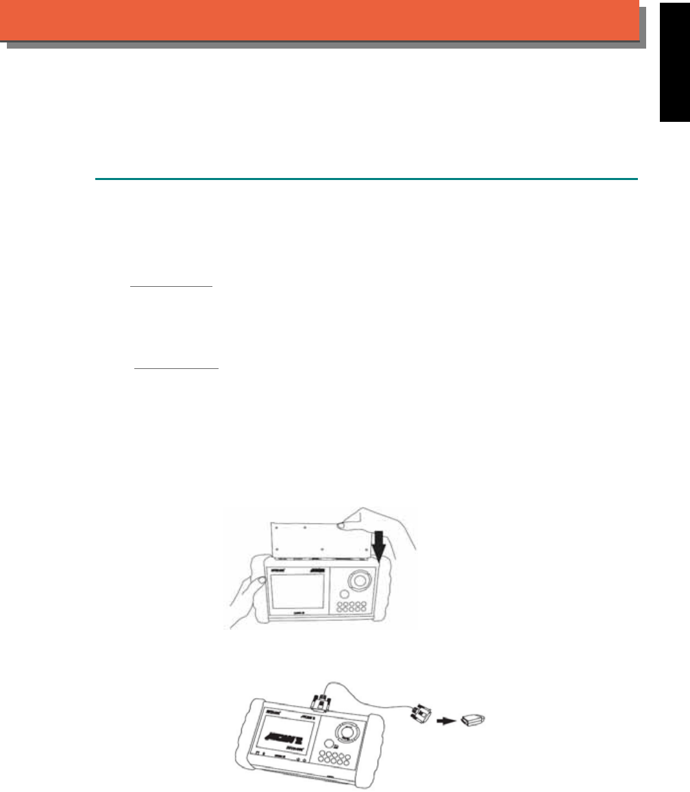
2. SELECT THE INTERFACE MODULE
There is only one interface module available for BMW diagnostic system, OBDII-IM5. Insert the
interface module into the base unit firmly if the socket in the vehicle is OBD-II, and connect the
adapter that corresponds to the socket, OBDII-AC-16P.
iSCAN-II for BMW © 2008 Autoland Scientech. Page 1
AUT
LAND
®
SCIENTECH
BMW Diag
3. CONNECT TO THE VEHICLE
Plug the available diagnostic adapter into the diagnostic socket in the vehicle. Select the BMW
Diag from the screen of iSCAN-II. Press ENTER to start the diagnostic function. If the model is
not listed on the screen, try to press RIGHT / LEFT buttons to turn the page.
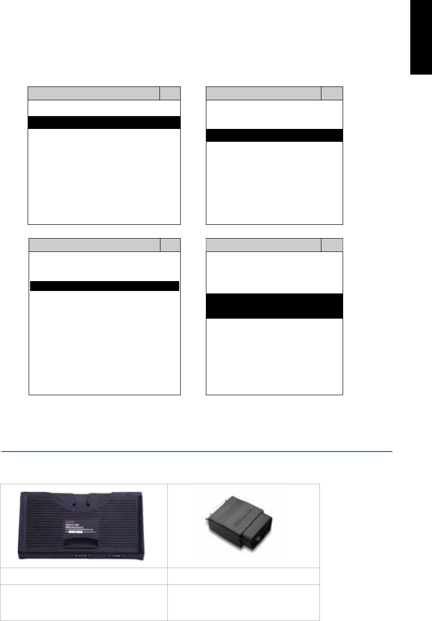
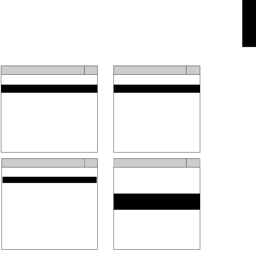
MAIN MENU
Vehicle Diagnostic
1 Vehicle Diagnostic 1 <ASIAN>
2 IMS
2
(Interface Module 2 <EUROPEAN>
Simulation System)
3 Component Test System
10 OBDII Standard Compliant
iSCAN-II(V1.00)
20 SETUP
<EUROPEAN>
BMW GT2
1 <BMW GT2> 1 BMW Diag
iSCAN-II (V1.00)
2 <FRENCH PKG>
3 MB
iSCAN-II (V1.00)
4 FIAT
iSCAN-II (V1.00)
2 BMW CODING
iSCAN-II (V1.00)
3 BMW SSS
iSCAN-II (V1.00)
4. MINI
5 JAGUAR
iSCAN-II (V1.00)
6 LANDROVER
iSCAN- II (V1.00)
iSCAN-II (V1.00)
The figure is for reference only. Autoland Scientech updates the software very often. The
screen shown may not be the same as the newest software delivered.
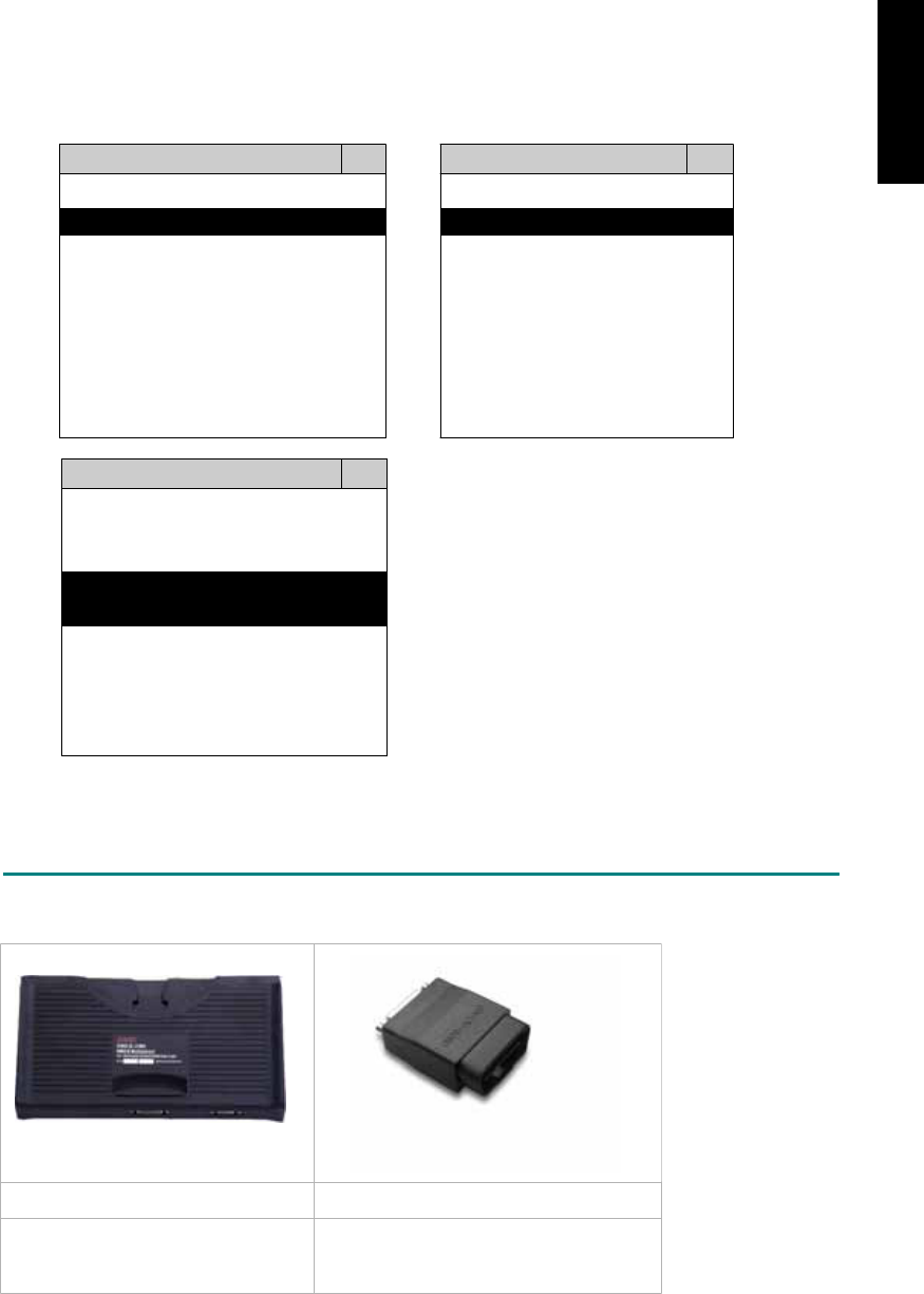
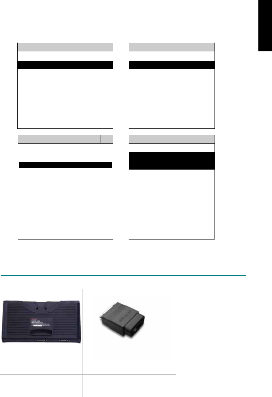
ADAPTERS AND INTERFACE MODULE
There is only one interface module available for the diagnostic system, OBDII-IM5.
OBDII-IM5 OBDII-AC-16P BM-AC1-20P
Insert this interface module for
the models equipped with only
OBD-II socket.
The most common adapter for
the new models from 2001.
Connect to the OBDII-IM5 with
AC-EC1.
The adapter for the old models
up to 2000. Connect directly to
iSCAN-II using BU-EC.
There are some adapters available. Refer to the “Diagnostic Cable Connection Quick Manual” for more
detailed connection / wiring information.
iSCAN-II for BMW © 2008 Autoland Scientech. Page 2
BMW Diag

START TO DIAGNOSE
Select BMW Diag by pressing the ENTER button. Turn ignition ON or make engine running at idle.
WARNING! Ignition ON without engine running may have a flat battery.
Select the system from the screen. There may be many systems on the vehicle, try to press RIGHT
button to turn the page. If the ECU response is successful, the screen will show all the available
functions.
BMW Dia
g
DME 7.2
1 1 series 1 ID CODES
2 3 series 2 READ FAULT CODE
3 5 series
4 6 series
5 7 series
3 CLEAR FAULT CODE
4 DATA STREAM
5 ACTIVATION
6 X series 6 ADAPTATION
7 EWS / DME S
y
nc
8 CAS / DME S
y
nc
The figure is for reference only. Autoland Scientech updates the software very often. The screen
shown may not be the same as the newest software delivered.
Autoland Scientech will keep updating the diagnostic software for BMW. Please refer to the software
specification.
Visit our website, http://www.autolandscientech.com , and apply for membership. You will get E-paper
every month and find more diagnostic technical information.
iSCAN-II for BMW © 2008 Autoland Scientech. Page 3
BMW Diag

TROUBLE SHOOTING
iSCAN-
II
never shows anything on LCD screen and there is no back-light?
1. Please check the cable and the connector again.
2. The voltage of the battery should be higher than 10V.
3. Check the power from OBD-II connector. PIN-16 is power, PIN-4 or PIN-5 is ground.
4. Check fuses in BU-EC (25-Pin Base Unit Extension Cable).
iSCAN-
II
never shows anything on LCD screen and the back-light is ON?
1. Check the diagnostic software using iSCAN-II/PSModule3 File Manager from PC. The
software for iSCAN-II may be missing or broken.
2. Adjust the brightness dial for the LCD panel. The brightness may be too dark.
Can't find the system on the screen?
1. Press Right button for more systems. There are too many systems which can't be shown
on the same page.
2. The diagnostic software does not have this system. Please refer to the specification. We
apologize for the inconvenience.
The green or yellow LED flashed on for a while then showed 'CONNECTION FAILED'
on the LCD screen?
1. Make sure the ignition is ON or make the engine running at idle.
2. Ignition OFF for a while, then Ignition ON and try again.
3. Check the cable and the adapter. Unplug all cables and adapters and plug-in again.
4. Make sure the vehicle equips with the correct system. For example, the manual
transmission will not have A/T transmission ECU.
5. The vehicle will NOT equip with all the systems listed on the software. Some special
systems are only available on the luxury models.
6. The ECU is malfunction or the diagnostic line from the ECU is open or short to the ground or
power.
7. Battery voltage is too low.
Successfully connects to the system but shows 'VERSION UNKNOWN' on the LCD
screen?
Due to the prompt development of the Motor manufactures, the diagnostic software might not
be able to communicate with all ECU versions. Download the newest software from the member
area of Autoland Scientech website and try again. (http://www.autolandscientech.com)
If the same situation occurs, please report the information of ID pages to our local distributors.
We will keep updating the diagnostic software for new ECUs. Please excuse any inconvenience
this may cause.
Successfully connects to the system but shows 'LINK FAILURE' on the title?
Some ECUs are not as stable as our research department expected. Please report the
information of ID pages to our local distributors. Our R/D department will do our best to fix the
problems as soon as possible. Please excuse any inconvenience this may cause.
After selecting the model, the green light is always ON before communication starts?
If the diagnostic circuit is shorted to ground or if a faulty control unit is in the vehicle, the green
or yellow LED light on the scanner will remain on steadily when the scanner is connected to the
vehicle diagnostic connector. Try to remove the faulty ECU from the bus.
Document Version 1.00 for iSCAN-II, © 2008 Autoland Scientech
The information contained herein is the exclusive property of Autoland Scientech
®
and shall not be distributed, reproduced, or disclosed
in whole or in part without prior written permission of Autoland Scientech
®
. Autoland Scientech
®
reserves the right to make any change
without notice. The trademarks mentioned belong to the owners.
iSCAN-II for BMW © 2008 Autoland Scientech. Page 4
BMW Diag
iSCAN-
II
Documentation
CHRYSLER
®
DIAGNOSTIC SYSTEM
GETTING STARTED
iSCAN-II CHRYSLER Diagnostic Software cover the following brand: Chrysler,
Dodge and Jeep.
1. FIND THE DIAGNOSTIC SOCKET
OBD-
II Socket
!!!!!
Most OBD-II diagnostic sockets are located under the steering wheel on driver or glove
!!!!!
compartment on passenger side.
!!!!!
OTHER Socket
!!!!!
iSCAN- II Chrysler Diagnostic Software does not support the vehicles which are equipped with
!!!!!
the other sockets.
2. SELECT THE INTERFACE MODULE
There is only one interface module available for CHRYSLER diagnostic system, OBDII-IM5.
Insert the interface module into the base unit firmly. Select the adapter that corresponds to the
socket, ex. OBDII-AC-16P.
ISCAN-II for CHRYSLER © 2008 Autoland Scientech. Page 1
AUT
LAND
®
SCIENTECH
CHRYSLER
3. CONNECT TO THE VEHICLE
Plug the available diagnostic adapter into the diagnostic socket in the vehicles. Select the
CHRYSLER from the screen of iSCAN-II . Press ENTER to start the diagnostic function. If the
model is not listed on the screen, try to press RIGHT / LEFT buttons to turn the page.
MAIN MENU
Vehicle Diagnostic
1 Vehicle Diagnostic 1 <ASIAN>
2 IMS
2
(Interface Module 2 <EUROPEAN>
Simulation System)
3 Component Test System
10 OBDII Standard Compliant
iSCAN-II (V1.00)
20 SETUP
<ASIAN>
1 <KOREA>
2 <JAPAN>
3 CHRYSLER
iSCAN-II (V1.00)
4 FORD OEM(OBDII 95~)
MAZDA OEM(OBDII 01~)
iSCAN-II (V1.00)
5. GM US
iSCAN-II (V1.00)
The figure is for reference only. Autoland Scientech updates the software very often. The
screen shown may not be the same as the newest software delivered.
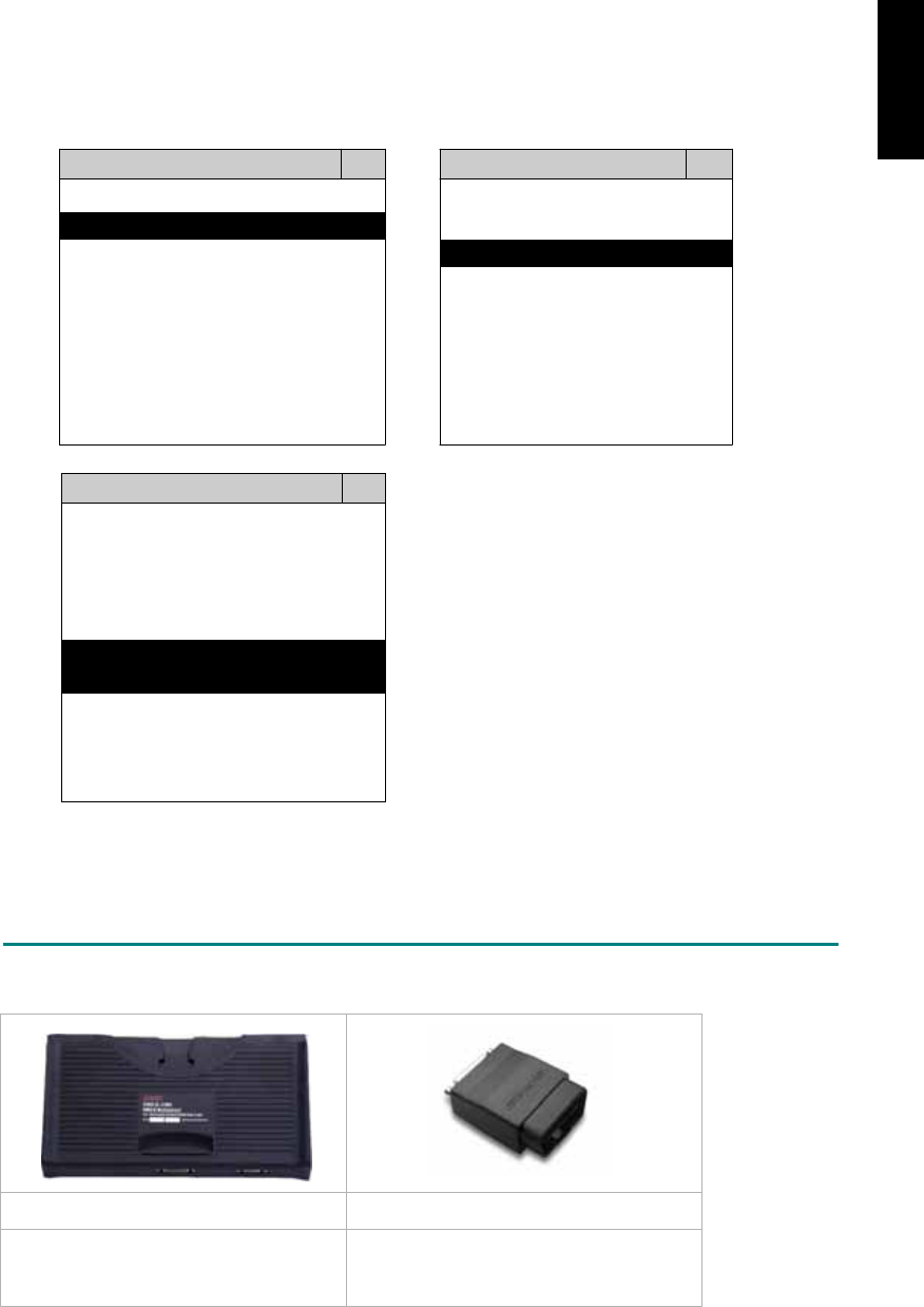
ADAPTERS AND INTERFACE MODULE
There is only one interface module available for the diagnostic system, OBDII-IM5.
OBDII-IM5 OBD
II
-AC-16P
OBD-II Full Specification Multiplexer The most common adapter for the new
models. Connect to the OBDII-IM5 with
AC-EC1.
There are some adapters available. Refer to the “Diagnostic Cable Connection Quick Manual” for more
detailed connection / wiring information.
ISCAN-II for CHRYSLER © 2008 Autoland Scientech. Page 2
CHRYSLER
START TO DIAGNOSE
Select CHRYSLER by pressing the ENTER button. Turn ignition ON or make engine running at idle.
WARNING! Ignition ON without engine running may have a flat battery.
Select the system from the screen. There may be many systems on the vehicle, try to press RIGHT
button to turn the page. If the ECU response is successful, the screen will show all the available
functions.
CHRYSLER ENGINE
1 ENGINE 1 ID CODES
2 A/T 2 READ FAULT CODE
3 ABS
4 SRS
3 CLEAR FAULT CODE
4 DATA STREAM
The figure is for reference only. Autoland Scientech updates the software very often. The screen
shown may not be the same as the newest software delivered.
Autoland Scientech will keep updating the diagnostic software for CHRYSLER. Please refer to the
software specification.
Visit our website, http://www.autolandscientech.com , and apply for membership. You will get E-paper
every month and find more diagnostic technical information.
ISCAN-II for CHRYSLER © 2008 Autoland Scientech. Page 3
CHRYSLER
CHRYSLER

TROUBLE SHOTTING
iSCAN-
II
never shows anything on LCD screen and there’s no back-light?
1. Please check the cable and the connector again.
2. The voltage of the battery should be higher than 10V.
3. Check the power from OBD-II connector. PIN-16 is power, PIN-4 or PIN-5 is ground.
4. Check fuses in BU-EC (25-Pin Base Unit Extension Cable).
iSCAN-
II
never shows anything on LCD screen and the back-light is ON?
1. Check the diagnostic software using iSCAN-II/PSModule3 File Manager from PC. The
software for iSCAN-II may be missing or broken.
2. Adjust the brightness dial for the LCD panel. The brightness may be too dark.
Can't find the system on the screen?
1. Press Right button for more systems. There are too many systems which can't be shown
on the same page.
2. The diagnostic software does not have this system. Please refer to the specification. We
apologize for the inconvenience.
The green or yellow LED flashed on for a while, then showed 'CONNECTION FAILED'
on the LCD screen?
1. Make sure the ignition is ON or make the engine running at idle.
2. Ignition OFF for a while, then Ignition ON and try again.
3. Check the cable and the adapter. Unplug all cables and adapters and plug-in again.
4. Make sure the vehicle equips with the correct system. For example, the manual
transmission will not have A/T transmission ECU.
5. The vehicle will NOT equip with all the systems listed on the software. Some special
systems are only available on the luxury models.
6. The ECU is malfunction or the diagnostic line from the ECU is open or short to the ground or
power.
7. Battery voltage is too low.
Successfully connected to the system but shows 'VERSION UNKNOWN' on the LCD
screen?
Due to the prompt development of the Motor manufactures, the diagnostic software might not
be able to communicate with all ECU versions. Download the newest software from the member
area of Autoland Scientech website and try again. (http://www.autolandscientech.com)
If the same situation occurs, please report the information of ID pages to our local distributors.
We will keep updating the diagnostic software for new ECUs. Please excuse any inconvenience
this may cause.
Successfully connects to the system but shows 'LINK FAILURE' on the title?
Some ECUs are not as stable as our research department expected. Please report the
information of ID pages to our local distributors. Our R/D department will do our best to fix the
problems as soon as possible. Please excuse any inconvenience this may cause.
Document Version 1.00 for iSCAN-II, © 2008 Autoland Scientech
The information contained herein is the exclusive property of Autoland Scientech
®
and shall not be distributed, reproduced, or disclosed
in whole or in part without prior written permission of Autoland Scientech
®
. Autoland Scientech
®
reserves the right to make any change
without notice. The trademarks mentioned belong to the owners.
ISCAN-II for CHRYSLER © 2008 Autoland Scientech. Page 4
CHRYSLER
iSCAN-
II
Documentation
CITROËN
®
DIAGNOSTIC SYSTEM
GETTING STARTED
1. FIND THE DIAGNOSTIC SOCKET
OBD-
II Soc ket
Most OBD-II diagnostic socket can be found under a plastic cover of dashboard on driver side.
Some of them can be found behind the ashtray box or the relay box.
OBD-II socket
2. SELECT THE INTERFACE MODULE
There is only one interface module available for CITROËN diagnostic system, OBDII-IM5.
Insert the interface module into the base unit firmly if the socket in the vehicle is OBD-II, and
connect the adapter that corresponds to the socket, OBDII-AC-16P.
iSCAN-II for CITROËN © 2008 Autoland Scientech. Page 1
AUT
LAND
®
SCIENTECH
CITROËN
3. CONNECT TO THE VEHICLE
Plug the available diagnostic adapter into the diagnostic socket in the vehicle. Select the
CITROEN from the screen of iSCAN-II. Press ENTER to start to diagnostic function. If the
model is not listed on the screen, try to press RIGHT / LEFT buttons to turn the page.
MAIN MENU
Vehicle Diagnostic
1 Vehicle Diagnostic 1 <ASIAN>
2 IMS
2
(Interface Module 2 <EUROPEAN>
Simulation System)
3 Component Test System
10 OBDII Standard Compliant
iSCAN-II(V1.00)
20 SETUP
<EUROPEAN>
FRENCH PKG
1 <BMW GT2>
2 <FRENCH PKG>
1 RENAULT
iSCAN-II (V1.00)
3 MB
iSCAN-II (V1.00)
4. FIAT
2 CITROEN
iSCAN-II (V1.00)
3 PEUGEOT
iSCAN-II (V1.00)
5. JAGUAR
iSCAN-II (V1.00)
iSCAN-II (V1.00)
6. LANDROVER
iSCAN-II (V1.00)
The figure is for reference only. Autoland Scientech updates the software very often. The
screen shown may not be the same as the newest software delivered.
ADAPTERS AND INTERFACE MODULE
There is only one interface module available for the diagnostic system, OBDII-IM5.
OBD
II
-IM5 OBD
II
-AC-16P
Insert this interface module for the models
equipped with only OBD-II socket.
The most common adapter for the
new models. Connect to the OBDII-
IM5 with AC-EC1.
There are some adapters available. Refer to the “Diagnostic Cable Connection Quick Manual” for more
detailed connection / wiring information.
iSCAN-II for CITROËN © 2008 Autoland Scientech. Page 2
CITROËN
START TO DIAGNOSE
Select CITROËN by pressing the ENTER button. Turn ignition ON or make engine running at idle.
WARNING! Ignition ON without engine running may have a flat battery.
Select the system from the screen. There may be many systems on the vehicle, try to press RIGHT
button to turn the page. If the ECU response is successful, the screen will show all the available
functions.
CITROEN ENGINE
1 BERLINGO 1 ID CODES
2 C2 2 READ FAULT CODE
3 C3
4 C4
5 C5
3 CLEAR FAULT CODE
4 DATA STREAM
6 C8
7 JUMPY
8 XSARA
The figure is for reference only. Autoland Scientech updates the software very often. The screen
shown may not be the same as the newest software delivered. We may simplify the steps of the
procedure.
Autoland Scientech will keep updating the diagnostic software for CITROËN. Please refer to the
software specification.
Visit our website, http://www.autolandscientech.com , and apply for membership. You will get E-paper
every month and find more diagnostic technical information.
iSCAN-II for CITROËN © 2008 Autoland Scientech. Page 3
CITROËN

TROUBLE SHOOTING
iSCAN-
II
never show anything on LCD screen and there’s no back-light?
1. Please check the cable and the connector again.
2. The voltage of the battery should be higher than 10V.
3. Check the power from OBD-II connector. PIN-16 is power, PIN-4 or PIN-5 is ground.
4. Check fuses in BU-EC (25-Pin Base Unit Extension Cable).
iSCAN-
II
never shows anything on LCD screen and the back-light is ON?
1. Check the diagnostic software using iSCAN-II/PSModule3 File Manager from PC. The
software for iSCAN-II may be missing or broken.
2. Adjust the brightness dial for the LCD panel. The brightness may be too dark.
Can't find the system on the screen?
1. Press Right button for more systems. There are too many systems which can't be shown
on the same page.
2. The diagnostic software does not have this system. Please refer to the specification. We
apologize for the inconvenience.
The green or yellow LED flashed on for a while then showed 'CONNECTION FAILED'
on the LCD screen?
1. Make sure the ignition is ON or make the engine running at idle.
2. Ignition OFF for a while, then Ignition ON and try again.
3. Check the cable and the adapter. Unplug all cables and adapters and plug-in again.
4. Make sure the vehicle equips with the correct system. For example, the manual
transmission will not have A/T transmission ECU.
5. The vehicle will NOT equip with all the systems listed on the software. Some special
systems are only available on the luxury models.
6. The ECU is malfunction or the diagnostic line from the ECU is open or short to the ground or
power.
7. Battery voltage is too low.
Successfully connects to the system but shows 'VERSION UNKNOWN' on the LCD
screen?
Due to the prompt development of the Motor manufactures, the diagnostic software might not
be able to communicate with all ECU versions. Download the newest software from the member
area of Autoland Scientech website and try again. (http://www.autolandscientech.com)
If the same situation occurs, please report the information of ID pages to our local distributors.
We will keep updating the diagnostic software for new ECUs. Please excuse any inconvenience
this may cause.
Successfully connects to the system but shows 'LINK FAILURE' on the title?
Some ECUs are not as stable as our research department expected. Please report the
information of ID pages to our local distributors. Our R/D department will do our best to fix the
problems as soon as possible. Please excuse any inconvenience this may cause.
Document Version 1.00 for iSCAN-II, © 2008 Autoland Scientech
The information contained herein is the exclusive property of Autoland Scientech
®
and shall not be distributed, reproduced, or disclosed
in whole or in part without prior written permission of Autoland Scientech
®
. Autoland Scientech
®
reserves the right to make any change
without notice. The trademarks mentioned belong to the owners.
iSCAN-II for CITROËN © 2008 Autoland Scientech. Page 4
CITROËN

iSCAN-
II
Documentation
DAEWOO
®
DIAGNOSTIC SYSTEM
GETTING STARTED
iSCAN- II Daewoo Diagnostic Software focus on Daewoo except GM Daewoo vehicles.
GM Daewoo, please select iSCAN-II GM Diagnostic Software for North America area.
1. FIND THE DIAGNOSTIC SOCKET
There are two kinds of diagnostic sockets for DAEWOO diagnostic system. Prior to the year
1998, most vehicles were equipped with 12-Pin socket.
OBD-
II Socket
Most OBD-II diagnostic sockets are located under the steering wheel on driver side.
OBD-II socket
12-PIN Soc ket
For the old models equipped with 12-PIN socket, please refer to the sticker direction under the
dashboard on driver side and near the steering column. Some models equip both of the
sockets, only 12-PIN socket can be worked.
2. SELECT THE INTERFACE MODULE
There is only one interface module available for DAEWOO diagnostic system, OBDII-IM5.
Insert the interface module into the base unit firmly. Select the adapter that corresponds to the
socket, ex. OBDII-AC-16P.
iSCAN-II for DAEWOO © 2008 Autoland Scientech. Page 1
AUT
LAND
®
SCIENTECH
DAEWOO
3. CONNECT TO THE VEHICLE
Plug the available diagnostic adapter into the diagnostic socket in the vehicle. Select the
DAEWOO from the screen of iSCAN-II . Press ENTER to start the diagnostic function. If the
model is not listed on the screen, try to press RIGHT / LEFT buttons to turn the page.
MAIN MENU
Vehicle Diagnostic
1 Vehicle Diagnostic 1 <ASIAN>
2 IMS
2
(Interface Module 2 <EUROPEAN>
Simulation System)
3 Component Test System
10 OBDII Standard Compliant
iSCAN-II (V1.00)
20 SETUP
<ASIAN>
<KOREA>
1 <KOREA>
2 <JAPAN>
1 DAEWOO
iSCAN-II (V1.00)
3 CHRYSLER
iSCAN-II (V1.00)
4 FORD OEM(OBDII 95~)
2 HYUNDAI
iSCAN-II (V1.00)
3 KIA
MAZDA OEM(OBDII 01~)
iSCAN-II (V1.00)
5. GM US
iSCAN-II (V1.00)
4 SSANGYONG
iSCAN-II (V1.00)
iSCAN-II (V1.00)
The figure is for reference only. Autoland Scientech updates the software very often. The
screen shown may not be the same as the newest software delivered.
ADAPTERS AND INTERFACE MODULE
There is only one interface module available for the diagnostic system, OBDII-IM5.
OBD
II
-IM5 OBD
II
-AC-16P GM-AC-12P
OBD-II Full Specification
Multiplexer
The most common adapter for the
new models. Connect to the
OBDII-IM5 with AC-EC1.
The adapter for the old models.
There are some adapters available. Refer to the “Diagnostic Cable Connection Quick Manual” for more
detailed connection / wiring information.
iSCAN-II for DAEWOO © 2008 Autoland Scientech. Page 2
DAEWOO

START TO DIAGNOSE
Select DAEWOO by pressing the ENTER button. Turn ignition ON or make engine running at idle.
WARNING! Ignition ON without engine running may have a flat battery.
Select the system from the screen. There may be many systems on the vehicle, try to press RIGHT
button to turn the page. If the ECU response is successful, the screen will show all the available
functions.
DAEWOO ENGINE
1 ENGINE 1 ID CODES
2 A/T 2 READ FAULT CODE
3 ABS
4 SRS
3 CLEAR FAULT CODE
4 DATA STREAM
The figure is for reference only. Autoland Scientech updates the software very often. The screen
shown may not be the same as the newest software delivered.
Autoland Scientech will keep updating the diagnostic software for DAEWOO. Please refer to the
software specification.
Visit our website, http://www.autolandscientech.com , and apply for membership. You will get E-paper
every month and find more diagnostic technical information.
iSCAN-II for DAEWOO © 2008 Autoland Scientech. Page 3
DAEWOO

TROUBLE SHOOTING
iSCAN-
II
never shows anything on LCD screen and there's no back-light?
1. Please check the cable and the connector again.
2. The voltage of the battery should be higher than 10V.
3. Check the power from OBD-II connector. PIN-16 is power, PIN-4 or PIN-5 is ground.
1. Check fuses in BU-EC (25-Pin Base Unit Extension Cable).
iSCAN-
II
never shows anything on LCD screen and the back-light is ON?
1. Check the diagnostic software using iSCAN-II/PSModule3 File Manager from PC. The
software for iSCAN-II may be missing or broken.
2. Adjust the brightness dial for the LCD panel. The brightness may be too dark.
Can't find the system on the screen?
1. Press Right button for more systems. There are too many systems which can't be shown
on the same page.
2. The diagnostic software does not have this system. Please refer to the specification. We
apologize for the inconvenience.
The green or yellow LED flashed on for a while, then showed 'CONNECTION FAILED'
on the LCD screen?
1. Make sure the ignition is ON or make the engine running at idle.
2. Ignition OFF for a while, then Ignition ON and try again.
3. Check the cable and the adapter. Unplug all cables and adapters and plug-in again.
4. Make sure the vehicle equips with the correct system. For example, the manual
transmission will not have A/T transmission ECU.
5. The vehicle will NOT equip with all the systems listed on the software. Some special
systems are only available on the luxury models.
6. The ECU is malfunction or the diagnostic line from the ECU is open or short to the ground or
power.
7. Battery voltage is too low.
Successfully connected to the system but shows 'VERSION UNKNOWN' on the LCD
screen?
Due to the prompt development of the Motor manufactures, the diagnostic software might not
be able to communicate with all ECU versions. Download the newest software from the member
area of Autoland Scientech website and try again. (http://www.autolandscientech.com)
If the same situation occurs, please report the information of ID pages to our local distributors.
We will keep updating the diagnostic software for new ECUs. Please excuse any inconvenience
this may cause.
Successfully connects to the system but shows 'LINK FAILURE' on the title?
Some ECUs are not as stable as our research department expected. Please report the
information of ID pages to our local distributors. Our R/D department will do our best to fix the
problems as soon as possible. Please excuse any inconvenience this may cause.
Document Version 1.00 for iSCAN-II, © 2008 Autoland Scientech
The information contained herein is the exclusive property of Autoland Scientech
®
and shall not be distributed, reproduced, or disclosed
in whole or in part without prior written permission of Autoland Scientech
®
. Autoland Scientech
®
reserve the right to make any change
without notice. The trademarks mentioned belong to the owners.
iSCAN-II for DAEWOO © 2008 Autoland Scientech. Page 4
DAEWOO

iSCAN-
II
Documentation
DAIHATSU
®
DIAGNOSTIC SYSTEM
GETTING STARTED
1. FIND THE DIAGNOSTIC SOCKET
OBD-
II
Socket
The OBD-II diagnostic socket is located under the steering wheel on driver side.
OBD-
II
socket
2. SELECT THE INTERFACE MODULE
There is only one interface module available for DAIHATSU diagnostic system, OBDII-IM5.
Insert the interface module into the base unit firmly. Select the adapter that corresponds to the
socket, ex. OBDII-AC-16P.
iSCAN-II for DAIHATSU © 2008 Autoland Scientech. Page 1
AUT
LAND
®
SCIENTECH
DAIHATSU
3. CONNECT TO THE VEHICLE
Plug the available diagnostic adapter into the diagnostic socket in the vehicles. Select the
DAIHATSU from the screen of iSCAN- II . Press ENTER to start the diagnostic function. If the
model is not listed on the screen, try to press RIGHT / LEFT buttons to turn the page.
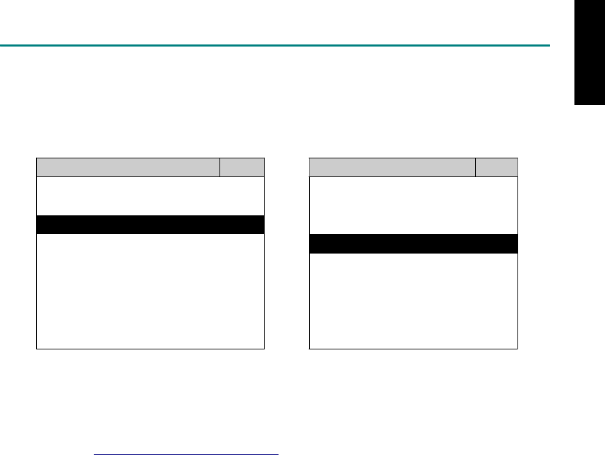
MAIN MENU
Vehicle Diagnostic
1 Vehicle Diagnostic 1 <ASIAN>
2 IMS
2
(Interface Module 2 <EUROPEAN>
Simulation System)
3 Component Test System
10 OBDII Standard Compliant
iSCAN-II (V1.00)
20 SETUP
<ASIAN>
<JAPAN>
1 <KOREA>
2 <JAPAN>
1 DAIHATSU NON-CAN
iSCAN-II (V1.00)
3 CHRYSLER
iSCAN-II (V1.00)
4 FORD OEM(OBDII 95~)
2 DAIHATSU CAN
iSCAN-II (V1.00)
3
HONDA
MAZDA OEM(OBDII 01~)
iSCAN-II (V1.00)
5. GM US
iSCAN-II (V1.00)
4 ACURA
iSCAN-II (V1.00)
iSCAN-II (V1.00) 5 ISUZU
iSCAN-II (V1.00)
The figure is for reference only. Autoland Scientech updates the software very often. The
screen shown may not be the same as the newest software delivered.
ADAPTERS AND INTERFACE MODULE
There is only one interface module available for the diagnostic system, OBDII-IM5.
OBD
II
-IM5 OBD
II
-AC-16P
OBD-II Full Specification
Multiplexer
The most common adapter for the
new models. Connect to the OBDII-
IM5 with AC-EC1.
There are some adapters available. Refer to the “Diagnostic Cable Connection Quick Manual” for more
detailed connection / wiring information.
iSCAN-II for DAIHATSU © 2008 Autoland Scientech. Page 2
DAIHATSU

START TO DIAGNOSE
Select DAIHATSU by pressing the ENTER button. Turn ignition ON or make engine running at idle.
WARNING! Ignition ON without engine running may have a flat battery.
Select the system from the screen. There may be many systems on the vehicle, try to press RIGHT
button to turn the page. If the ECU response is successful, the screen will show all the available
functions.
DAIHATSU ENGINE
1 ENGINE 1 ID CODES
2 A/T 2 READ FAULT CODE
3 ABS
4 SRS
5 EPS
3 CLEAR FAULT CODE
4 DATA STREAM
The figure is for reference only. Autoland Scientech updates the software very often. The screen
shown may not be the same as the newest software delivered.
Autoland Scientech will keep updating the diagnostic software for DAIHATSU. Please refer to the
software specification.
Visit our website, http://www.autolandscientech.com , and apply for membership. You will get E-paper
every month and find more diagnostic technical information.
iSCAN-II for DAIHATSU © 2008 Autoland Scientech. Page 3
DAIHATSU

TROUBLE SHOOTING
iSCAN-
II
never shows anything on LCD screen and there's no back-light?
1. Please check the cable and the connector again.
2. The voltage of the battery should be higher than 10V.
3. Check the power from OBD-II connector. PIN-16 is power, PIN-4 or PIN-5 is ground.
4. Check fuses in BU-EC (25-Pin Base Unit Extension Cable).
iSCAN-
II
never shows anything on LCD screen and the back-light is ON?
1. Check the diagnostic software using iSCAN-II/PSModule3 File Manager from PC. The
software for iSCAN-II may be missing or broken.
2. Adjust the brightness dial for the LCD panel. The brightness may be too dark.
Can't find the system on the screen?
1. Press Right button for more systems. There are too many systems which can't be shown
on the same page.
2. The diagnostic software does not have this system. Please refer to the specification. We
apologize for the inconvenience.
The green or yellow LED flashed on for a while, then showed 'CONNECTION FAILED'
on the LCD screen?
1. Make sure the ignition is ON or make the engine running at idle.
2. Ignition OFF for a while, then Ignition ON and try again.
3. Check the cable and the adapter. Unplug all cables and adapters and plug-in again.
4. Make sure the vehicle equips with the correct system. For example, the manual
transmission will not have A/T transmission ECU.
5. The vehicle will NOT equip with all the systems listed on the software. Some special
systems are only available on the luxury models.
6. The ECU is malfunction or the diagnostic line from the ECU is open or short to the ground or
power.
7. Battery voltage is too low.
Successfully connected to the system but shows 'VERSION UNKNOWN' on the LCD
screen?
Due to the prompt development of the Motor manufactures, the diagnostic software might not
be able to communicate with all ECU versions. Download the newest software from the member
area of Autoland Scientech website and try again. (http://www.autolandscientech.com)
If the same situation occurs, please report the information of ID pages to our local distributors.
We will keep updating the diagnostic software for new ECUs. Please excuse any inconvenience
this may cause.
Successfully connects to the system but shows 'LINK FAILURE' on the title?
Some ECUs are not as stable as our research department expected. Please report the
information of ID pages to our local distributors. Our R/D department will do our best to fix the
problems as soon as possible. Please excuse any inconvenience this may cause.
Document Version 1.00 for iSCAN-II, © 2008 Autoland Scientech
The information contained herein is the exclusive property of Autoland Scientech
®
and shall not be distributed, reproduced, or disclosed
in whole or in part without prior written permission of Autoland Scientech
®
. Autoland Scientech
®
reserve the right to make any change
without notice. The trademarks mentioned belong to the owners.
iSCAN-II for DAIHATSU © 2008 Autoland Scientech. Page 4
DAIHATSU
iSCAN-
II
Documentation
FIAT
®
DIAGNOSTIC SYSTEM
GETTING STARTED
1. FIND THE DIAGNOSTIC SOCKET
OBD-
II
Soc
ket
Most OBD-II diagnostic socket can be found under the dashboard on driver side and are
covered by a plastic cover.
OBD-
II
socket
Other Soc ket
iSCAN-II FIAT Diagnostic Software does not support the vehicles which are equipped with the
other sockets.
2. SELECT THE INTERFACE MODULE
There is only one interface module available for FIAT diagnostic system, OBDII-IM5. Insert the
interface module into the base unit firmly if the socket in the vehicle is OBD-II, and connect the
adapter that corresponds to the socket, OBDII-AC-16P.
iSCAN-II for FIAT © 2008 Autoland Scientech. Page 1
AUT
LAND
®
SCIENTECH
FIAT
3. CONNECT TO THE VEHICLE
Plug the available diagnostic adapter into the diagnostic socket in the vehicle. Select the FIAT
from the screen of iSCAN-II . Press ENTER to start to diagnostic function. If the model is not
listed on the screen, try to press RIGHT / LEFT buttons to turn the page.
MAIN MENU
Vehicle Diagnostic
1 Vehicle Diagnostic 1 <ASIAN>
2 IMS
2
(Interface Module 2 <EUROPEAN>
Simulation System)
3 Component Test System
10 OBDII Standard Compliant
iSCAN-II(V1.00)
20 SETUP
<EUROPEAN>
1 <BMW GT2>
2 <FRENCH PKG>
3 MB
iSCAN-II (V1.00)
4. FIAT
iSCAN-II (V1.00)
5. JAGUAR
iSCAN-II (V1.00)
6. LANDROVER
iSCAN-II (V1.00)
The figure is for reference only. Autoland Scientech updates the software very often. The
screen shown may not be the same as the newest software delivered.
ADAPTERS AND INTERFACE MODULE
There is only one interface module available for the diagnostic system, OBDII-IM5.
OBD
II
-IM5 OBD
II
-AC-16P
Insert this interface module for the
models equipped with only OBD-II
socket.
The most common adapter for the new
models. Connect to the OBDII-IM5 with
AC-EC1.
There are some adapters available. Refer to the “Diagnostic Cable Connection Quick Manual” for more
detailed connection / wiring information.
iSCAN-II for FIAT © 2008 Autoland Scientech. Page 2
FIAT

START TO DIAGNOSE
Select FIAT by pressing the ENTER button. Turn ignition ON or make engine running at idle.
WARNING! Ignition ON without engine running may have a flat battery.
Select the system from the screen. There may be many systems on the vehicle, try to press RIGHT
button to turn the page. If the ECU response is successful, the screen will show all the available
functions.
FIAT TRANSMISSION
1 ENGINE 1 ID CODES
2 TRANSMISSION 2 READ FAULT CODE
3 ABS
4 SRS
3 CLEAR FAULT CODE
4 DATA STREAM
The figure is for reference only. Autoland Scientech updates the software very often. The screen
shown may not be the same as the newest software delivered. We may simplify the steps of the
procedure.
Autoland Scientech will keep updating the diagnostic software for FIAT. Please refer to the software
specification.
Visit our website, http://www.autolandscientech.com , and apply for membership. You will get E-paper
every month and find more diagnostic technical information.
iSCAN-II for FIAT © 2008 Autoland Scientech. Page 3
FIAT

TROUBLE SHOOTING
iSCAN-
II
never shows anything on LCD screen and there’s no back-light?
1. Please check the cable and the connector again.
2. The voltage of the battery should be higher than 10V.
3. Check the power from OBD-II connector. PIN-16 is power, PIN-4 or PIN-5 is ground.
4. Check fuses in BU-EC (25-Pin Base Unit Extension Cable).
iSCAN-
II
never shows anything on LCD screen and the back-light is ON?
1. Check the diagnostic software using iSCAN-II/PSModule3 File Manager from PC. The
software for iSCAN-II may be missing or broken.
2. Adjust the brightness dial for the LCD panel. The brightness may be too dark.
Can't find the system on the screen?
1. Press Right button for more systems. There are too many systems which can't be shown
on the same page.
2. The diagnostic software do not have this system. Please refer to the specification. We
apologize for the inconvenience.
The green or yellow LED flashed on for a while then showed 'CONNECTION FAILED'
on the LCD screen?
1. Make sure the ignition is ON or make the engine running at idle.
2. Ignition OFF for a while, then Ignition ON and try again.
3. Check the cable and the adapter. Unplug all cables and adapters and plug-in again.
4. Make sure the vehicle equips with the correct system. For example, the manual
transmission will not have A/T transmission ECU.
5. The vehicle will NOT equip with all the systems listed on the software. Some special
systems are only available on the luxury models.
6. The ECU is malfunction or the diagnostic line from the ECU is open or short to the ground or
power.
7. Battery voltage is too low.
Successfully connects to the system but shows 'VERSION UNKNOWN' on the LCD
screen?
Due to the prompt development of the Motor manufactures, the diagnostic software might not
be able to communicate with all ECU versions. Download the newest software from the member
area of Autoland Scientech website and try again. (http://www.autolandscientech.com)
If the same situation occurs, please report the information of ID pages to our local distributors.
We will keep updating the diagnostic software for new ECUs. Please excuse any inconvenience
this may cause.
Successfully connects to the system but shows 'LINK FAILURE' on the title?
Some ECUs are not as stable as our research department expected. Please report the
information of ID pages to our local distributors. Our R/D department will do our best to fix the
problems as soon as possible. Please excuse any inconvenience this may cause.
Document Version 1.00 for iSCAN-II, © 2008 Autoland Scientech
The information contained herein is the exclusive property of Autoland Scientech
®
and shall not be distributed, reproduced, or disclosed
in whole or in part without prior written permission of Autoland Scientech
®
. Autoland Scientech
®
reserves the right to make any change
without notice. The trademarks mentioned belong to the owners.
iSCAN-II for FIAT © 2008 Autoland Scientech. Page 4
FIAT
iSCAN-
II
Documentation
!
!!
!FORD
®
DIAGNOSTIC SYSTEM
GETTING STARTED
1. FIND THE DIAGNOSTIC SOCKET
OBD-
II Socket
Most OBD-II diagnostic sockets are located under the steering wheel on driver side.
OBD-II socket
OTHER Socket
If another connector is found, ex. 17+8 / 6+1 / 20-PIN socket, please select iSCAN-II MAZDA
Diagnostic Software.
2. SELECT THE INTERFACE MODULE
There is only one interface module available for FORD diagnostic system, OBDII-IM5. Insert
the interface module into the base unit firmly. Select the adapter that corresponds to the socket,
ex. OBDII-AC-16P.
ISCAN-II for FORD © 2008 Autoland Scientech. Page 1
AUT
LAND
®
SCIENTECH
FORD
3. CONNECT TO THE VEHICLE
Plug the available diagnostic adapter into the diagnostic socket in the vehicle. Select the FORD
from the screen of iSCAN- II . Press ENTER to start the diagnostic function. If the model is not
listed on the screen, try to press RIGHT / LEFT buttons to turn the page.
MAIN MENU
Vehicle Diagnostic
1 Vehicle Diagnostic 1 <ASIAN>
2 IMS
2
(Interface Module 2 <EUROPEAN>
Simulation System)
3 Component Test System
10 OBDII Standard Compliant
iSCAN-II (V1.00)
20 SETUP
<ASIAN>
1 <KOREA>
2 <JAPAN>
3 CHRYSLER
iSCAN-II (V1.00)
4 FORD OEM(OBDII 95~)
MAZDA OEM(OBDII 01~)
iSCAN-II (V1.00)
5. GM US
iSCAN-II (V1.00)
The figure is for reference only. Autoland Scientech updates the software very often. The
screen shown may not be the same as the newest software delivered.
ADAPTERS AND INTERFACE MODULE
There is only one interface module available for the diagnostic system, OBDII-IM5.
OBD
II
-IM5 OBD
II
-AC-16P
OBD-II Full Specification
Multiplexer
The most common adapter for the
new models. Connect to the OBDII-
IM5 with AC-EC1.
There are some adapters available. Refer to the “Diagnostic Cable Connection Quick Manual” for more
detailed connection / wiring information.
ISCAN-II for FORD © 2008 Autoland Scientech. Page 2
FORD
START TO DIAGNOSE
Select FORD by pressing the ENTER button. Turn ignition ON or make engine running at idle.
WARNING! Ignition ON without engine running may have a flat battery.
Select the system from the screen. There may be many systems on the vehicle, try to press RIGHT
button to turn the page. If the ECU response is successful, the screen will show all the available
functions.
FORD ENGINE
1 ENGINE 1 ID CODES
2 A/T 2 READ FAULT CODE
3 ABS
4 SRS
3 CLEAR FAULT CODE
4 DATA STREAM
The figure is for reference only. Autoland Scientech updates the software very often. The screen
shown may not be the same as the newest software delivered.
Autoland Scientech will keep updating the diagnostic software for FORD. Please refer to the software
specification.
Visit our website, http://www.autolandscientech.com , and apply for membership. You will get E-paper
every month and find more diagnostic technical information.
ISCAN-II for FORD © 2008 Autoland Scientech. Page 3
FORD

TROUBLE SHOOTING
iSCAN-II never shows anything on LCD screen and there’s no back-light?
1. Please check the cable and the connector again.
2. The voltage of the battery should be higher than 10V.
3. Check the power from OBD-II connector. PIN-16 is power, PIN-4 or PIN-5 is ground.
4. Check fuses in BU-EC (25-Pin Base Unit Extension Cable).
iSCAN-
II
never shows anything on LCD screen and the back-light is ON?
1. Check the diagnostic software using iSCAN-II/PSModule3 File Manager from PC. The
software for iSCAN-II may be missing or broken.
2. Adjust the brightness dial for the LCD panel. The brightness may be too dark.
Can't find the system on the screen?
1. Press Right button for more systems. There are too many systems which can't be shown
on the same page.
2. The diagnostic software does not have this system. Please refer to the specification. We
apologize for the inconvenience.
The green or yellow LED flashed on for a while then showed 'CONNECTION FAILED'
on the LCD screen?
1. Make sure the ignition is ON or make the engine running at idle.
2. Ignition OFF for a while, then Ignition ON and try again.
3. Check the cable and the adapter. Unplug all cables and adapters and plug-in again.
4. Make sure the vehicle equips with the correct system. For example, the manual
transmission will not have A/T transmission ECU.
5. The vehicle will NOT equip with all the systems listed on the software. Some special
systems are only available on the luxury models.
6. The ECU is malfunction or the diagnostic line from the ECU is open or short to the ground or
power.
7. Battery voltage is too low.
Successfully connects to the system but shows 'VERSION UNKNOWN' on the LCD
screen?
Due to the prompt development of the Motor manufactures, the diagnostic software might not
be able to communicate with all ECU versions. Download the newest software from the member
area of Autoland Scientech website and try again. (http://www.autolandscientech.com)
If the same situation occurs, please report the information of ID pages to our local distributors.
We will keep updating the diagnostic software for new ECUs. Please excuse any inconvenience
this may cause.
Successfully connects to the system but shows 'LINK FAILURE' on the title?
Some ECUs are not as stable as our research department expected. Please report the
information of ID pages to our local distributors. Our R/D department will do our best to fix the
problems as soon as possible. Please excuse any inconvenience this may cause.
Document Version 1.00 for iSCAN-II, © 2008 Autoland Scientech
The information contained herein is the exclusive property of Autoland Scientech
®
and shall not be distributed, reproduced, or disclosed
in whole or in part without prior written permission of Autoland Scientech
®
. Autoland Scientech
®
reserves the right to make any change
without notice. The trademarks mentioned belong to the owners.
ISCAN-II for FORD © 2008 Autoland Scientech. Page 4
FORD
iSCAN-
II
Documentation
GM
®
DIAGNOSTIC SYSTEM
GETTING STARTED
The iSCAN- II GM Diagnostic Software cover the following brand: Buick, Cadillac, Chevrolet,
GM Daewoo, GMC, Hummer, Oldsmobile, Pontiac and Saturn.
For old Daewoo, please select iSCAN- II DAEWOO Diagnostic Software.
For Opel / Vauxhall, please select iSCAN-II OPEL Diagnostic Software.
For Saab, please select iSCAN-II SAAB Diagnostic Software.
For Holden, please select iSCAN- II HOLDEN Diagnostic Software.
1. FIND THE DIAGNOSTIC SOCKET
OBD-
II Socket
Most OBD-II diagnostic sockets are located under the steering wheel on driver side or under the
glove compartment on passenger's.
OTHER Socket
iSCAN-II GM Diagnostic Software does not support the 10-Pin and 12-Pin socket models for old
GM vehicles.
2. SELECT THE INTERFACE MODULE
There is only one interface module available for GM diagnostic system, OBDII-IM5. Insert the
interface module into the base unit firmly. Select the adapter that corresponds to the socket, ex.
OBDII-AC-16P.
ISCAN-II for GM © 2008 Autoland Scientech. Page 1
AUT
LAND
®
SCIENTECH
GM
3. CONNECT TO THE VEHICLE
Plug the available diagnostic adapter into the diagnostic socket in the vehicles. Select the GM
from the screen of iSCAN- II . Press ENTER to start the diagnostic function. If the model is not
listed on the screen, try to press RIGHT / LEFT buttons to turn the page.
MAIN MENU
Vehicle Diagnostic
1 Vehicle Diagnostic 1 <ASIAN>
2 IMS
2
(Interface Module 2 <EUROPEAN>
Simulation System)
3 Component Test System
10 OBDII Standard Compliant
iSCAN-II (V1.00)
20 SETUP
<ASIAN>
1 <KOREA>
2 <JAPAN>
3 CHRYSLER
iSCAN-II (V1.00)
4 FORD OEM(OBDII 95~)
MAZDA OEM(OBDII 01~)
iSCAN-II (V1.00)
5. GM
iSCAN-II (V1.00)
The figure is for reference only. Autoland Scientech updates the software very often. The
screen shown may not be the same as the newest software delivered.
ADAPTERS AND INTERFACE MODULE
There is only one interface module available for the diagnostic system, OBDII-IM5.
OBD
II
-IM5 OBD
II
-AC-16P
OBD-II Full Specification Multiplexer The most common adapter for the
new models. Connect to the OBDII-
IM5 with AC-EC1.
There are some adapters available. Refer to the “Diagnostic Cable Connection Quick Manual” for more
detailed connection / wiring information.
ISCAN-II for GM © 2008 Autoland Scientech. Page 2
GM
START TO DIAGNOSE
Select GM by pressing the ENTER button. Turn ignition ON or make engine running at idle.
WARNING! Ignition ON without engine running may have a flat battery.
Select the system from the screen. There may be many systems on the vehicle, try to press RIGHT
button to turn the page. If the ECU response is successful, the screen will show all the available
functions.
GM ENGINE
1 ENGINE 1 ID CODES
2 A/T 2 READ FAULT CODE
3 ABS
4 SRS
3 CLEAR FAULT CODE
4 DATA STREAM
The figure is for reference only. Autoland Scientech updates the software very often. The screen
shown may not be the same as the newest software delivered.
Autoland Scientech will keep updating the diagnostic software for GM. Please refer to the software
specification.
Visit our website, http://www.autolandscientech.com , and apply for membership. You will get E-paper
every month and find more diagnostic technical information.
ISCAN-II for GM © 2008 Autoland Scientech. Page 3
GM
GM

TROUBLE SHOTTING
iSCAN-
II
never shows anything on LCD screen and there’s no back-light?
1. Please check the cable and the connector again.
2. The voltage of the battery should be higher than 10V.
3. Check the power from OBD-II connector. PIN-16 is power, PIN-4 or PIN-5 is ground.
4. Check fuses in BU-EC (25-Pin Base Unit Extension Cable).
iSCAN-
II
never shows anything in LCD screen and the back-light is ON?
1. Check the diagnostic software using iSCAN-II/PSModule3 File Manager from PC. The
software for iSCAN-II may be missing or broken.
2. Adjust the brightness dial for the LCD panel. The brightness may be too dark.
Can't find the system on the screen?
1. Press Right button for more systems. There are too many systems which can't be shown
on the same page.
2. The diagnostic software does not have this system. Please refer to the specification. We
apologize for the inconvenience.
The green or yellow LED flashed on for a while, then shows 'CONNECTION FAILED'
on the LCD screen?
1. Make sure the ignition is ON or make the engine running at idle.
2. Ignition OFF for a while, then Ignition ON and try again.
3. Check the cable and the adapter. Unplug all cables and adapters and plug-in again.
4. Make sure the vehicle equips with the correct system. For example, the manual
transmission will not have A/T transmission ECU.
5. The vehicle will NOT equip with all the systems listed on the software. Some special
systems are only available on the luxury models.
6. The ECU is malfunction or the diagnostic line from the ECU is open or short to the ground or
power.
7. Battery voltage is too low.
Successfully connected to the system but shows 'VERSION UNKNOWN' on the LCD
screen?
Due to the prompt development of the Motor manufactures, the diagnostic software might not
be able to communicate with all ECU versions. Download the newest software from the member
area of Autoland Scientech website and try again. (http://www.autolandscientech.com)
If the same situation occurs, please report the information of ID pages to our local distributors.
We will keep updating the diagnostic software for new ECUs. Please excuse any inconvenience
this may cause.
Successfully connects to the system but shows 'LINK FAILURE' on the title?
Some ECUs are not as stable as our research department expected. Please report the
information of ID pages to our local distributors. Our R/D department will do our best to fix the
problems as soon as possible. Please excuse any inconvenience this may cause.
Document Version 1.00 for iSCAN-II, © 2008 Autoland Scientech
The information contained herein is the exclusive property of Autoland Scientech
®
and shall not be distributed, reproduced, or disclosed
in whole or in part without prior written permission of Autoland Scientech
®
. Autoland Scientech
®
reserves the right to make any change
without notice. The trademarks mentioned belong to the owners.
ISCAN-II for GM © 2008 Autoland Scientech. Page 4
GM
iSCAN-
II
Documentation
HYUNDAI
®
DIAGNOSTIC SYSTEM
GETTING STARTED
1. FIND THE DIAGNOSTIC SOCKET
There are two kinds of diagnostic sockets for HYUNDAI diagnostic system. Prior to the year
2000, most vehicles were equipped with 12-Pin socket.
OBD- II Socket
Most OBD-II diagnostic sockets are located under the steering wheel on driver side. For new
models after 2006, the communication protocol of ECUs is CAN. Please use OBDII-IM5 first on
new models, then try ASIAN-IM1 if the communication with some systems are failed.
OBD-
II
socket
12-PIN Soc ket
For the old models equipped with 12-PIN round socket, located in the fuse box under the
steering wheel on driver side. Some models may be equipped with OBD-II and 12-PIN
connectors together. Try both connectors by using ASIAN-IM1.
2. SELECT THE INTERFACE MODULE
There are two interface modules available for HYUNDAI diagnostic system, OBDII-IM5 and
ASIAN-IM1. Insert the interface module into the base unit firmly. Select the adapter that
corresponds to the socket, ex. OBDII-AC-16P.
iSCAN-II for HYUNDAI © 2008 Autoland Scientech. Page 1
AUT
LAND
®
SCIENTECH
HYUNDAI
3. CONNECT TO THE VEHICLE
Plug the diagnostic adapter into the diagnostic socket in the vehicle. Select the HYUNDAI from
the screen of iSCAN- II . Press ENTER to start to diagnostic function. If the model is not listed on
the screen, try to press RIGHT / LEFT buttons to turn the page. If the model equipped with 12-
PIN diagnostic socket, plug the ashtray lighter power cable, BU-EC-1. 12-PIN diagnostic
connector should connect to ASIAN-IM1, MIT port.
MAIN MENU
Vehicle Diagnostic
1 Vehicle Diagnostic 1 <ASIAN>
2 IMS
2
(Interface Module 2 <EUROPEAN>
Simulation System)
3 Component Test System
10 OBDII Standard Compliant
iSCAN-II (V1.00)
20 SETUP
<ASIAN>
<KOREA>
1 <KOREA>
2 <JAPAN>
1 DAEWOO
iSCAN-II (V1.00)
3 CHRYSLER
iSCAN-II (V1.00)
4 FORD OEM(OBDII 95~)
2 HYUNDAI
iSCAN-II (V1.00)
3 KIA
MAZDA OEM(OBDII 01~)
iSCAN-II (V1.00)
5. GM US
iSCAN-II (V1.00)
4 SSANGYONG
iSCAN-II (V1.00)
iSCAN-II (V1.00)
The figure is for reference only. Autoland Scientech updates the software very often. The
screen shown may not be the same as the newest software delivered.
iSCAN-II for HYUNDAI © 2008 Autoland Scientech. Page 2
HYUNDAI
ADAPTERS AND INTERFACE MODULE
There are two interface modules available for the diagnostic system, OBDII-IM5 and ASIAN-IM1.
OBD
II
-IM5 ASIAN-IM1
OBD-II Full Specification Multiplexer ASIAN Interface Module for TOYOTA / NISSAN /
MITSUBISHI / HYUNDAI / KIA
OBD
II
-AC-16P MIT-AC-12P BU-EC-1
The most common adapter for
the new models. Connect to the
OBDII-IM5 or ASIAN-IM1 with
AC-EC1.
The adapter for the old models.
Connect to the ASIAN-IM1 with
AC-EC1.
Ashtray lighter power cable, the
power source for 12-PIN
diagnostic socket models.
There are some adapters available. Refer to the “Diagnostic Cable Connection Quick Manual” for more
detailed connection / wiring information.
iSCAN-II for HYUNDAI © 2008 Autoland Scientech. Page 3
HYUNDAI

START TO DIAGNOSE
Select HYUNDAI by pressing the ENTER button. Turn ignition ON or make engine running at idle.
WARNING! Ignition ON without engine running may have a flat battery.
Select the system from the screen. There may be many systems on the vehicle, try to press RIGHT
button to turn the page. If the ECU response is successful, the screen will show all the available
functions.
HYUNDAI ENGINE
1 ENGINE 1 ID CODES
2 A/T 2 READ FAULT CODE
3 ABS
4 SRS
3 CLEAR FAULT CODE
4 DATA STREAM
5 ACTIVATION
The figure is for reference only. Autoland Scientech updates the software very often. The screen
shown may not be the same as the newest software delivered. We may simplify the steps of the
procedure.
Autoland Scientech will keep updating the diagnostic software for HYUNDAI. Please refer to the
software specification.
Visit our website, http://www.autolandscientech.com , and apply for membership. You will get E-paper
every month and find more diagnostic technical information.
iSCAN-II for HYUNDAI © 2008 Autoland Scientech. Page 4
HYUNDAI

TROUBLE SHOOTING
iSCAN-
II
never shows anything on LCD screen and there's no back-light?
1. Please check the cable and the connector again.
2. The voltage of the battery should be higher than 10V.
3. Check the power from OBD-II connector. PIN-16 is power, PIN-4 or PIN-5 is ground.
4. Check fuses in BU-EC (25-Pin Base Unit Extension Cable).
iSCAN-
II
never shows anything on LCD screen and the back-light is ON?
1. Check the diagnostic software using iSCAN-II/PSModule3 File Manager from PC. The
software for iSCAN-II may be missing or broken.
2. Adjust the brightness dial for the LCD panel. The brightness may be too dark.
Can't find the system on the screen?
1. Press Right button for more systems. There are too many systems which can't be shown
on the same page.
2. The diagnostic software does not have this system. Please refer to the specification. We
apologize for the inconvenience.
The green or yellow LED flashed on for a while, then showed 'CONNECTION FAILED'
on the LCD screen?
1. Make sure the ignition is ON or make the engine running at idle.
2. Ignition OFF for a while, then Ignition ON and try again.
3. Check the cable and the adapter. Unplug all cables and adapters and plug-in again.
4. Make sure the vehicle equips with the correct system. For example, the manual
transmission will not have A/T transmission ECU.
5. The vehicle will NOT equip with all the systems listed on the software. Some special
systems are only available on the luxury models.
6. The ECU is malfunction or the diagnostic line from the ECU is open or short to the ground or
power.
7. Battery voltage is too low.
Successfully connected to the system but shows 'VERSION UNKNOWN' on the LCD
screen?
Due to the prompt development of the Motor manufactures, the diagnostic software might not
be able to communicate with all ECU versions. Download the newest software from the member
area of Autoland Scientech website and try again. (http://www.autolandscientech.com)
If the same situation occurs, please report the information of ID pages to our local distributors.
We will keep updating the diagnostic software for new ECUs. Please excuse any inconvenience
this may cause.
Successfully connects to the system but shows 'LINK FAILURE' on the title?
Some ECUs are not as stable as our research department expected. Please report the
information of ID pages to our local distributors. Our R/D department will do our best to fix the
problems as soon as possible. Please excuse any inconvenience this may cause.
For models manufactured at 2006, which interface module should I insert?
Try OBDII-IM5 first, then ASIAN-IM1. OBDII-IM5 is applicable to CAN-protocol, and ASIAN-
IM1 is to HYUNDAI specific protocol. To connect with CAN-protocol models, ASIAN-IM1 may
send traditional signals to interrupt the inter-connection of the CAN-bus and cause fault codes.
Please use OBDII-IM5 with iSCAN-II HYUNDAI diagnostic software to clear the fault codes.
Document Version 1.00 for iSCAN-II, © 2008 Autoland Scientech
The information contained herein is the exclusive property of Autoland Scientech
®
and shall not be distributed, reproduced, or disclosed
in whole or in part without prior written permission of Autoland Scientech
®
. Autoland Scientech
®
reserve the right to make any change
without notice. The trademarks mentioned belong to the owners.
iSCAN-II for HYUNDAI © 2008 Autoland Scientech. Page 5
HYUNDAI
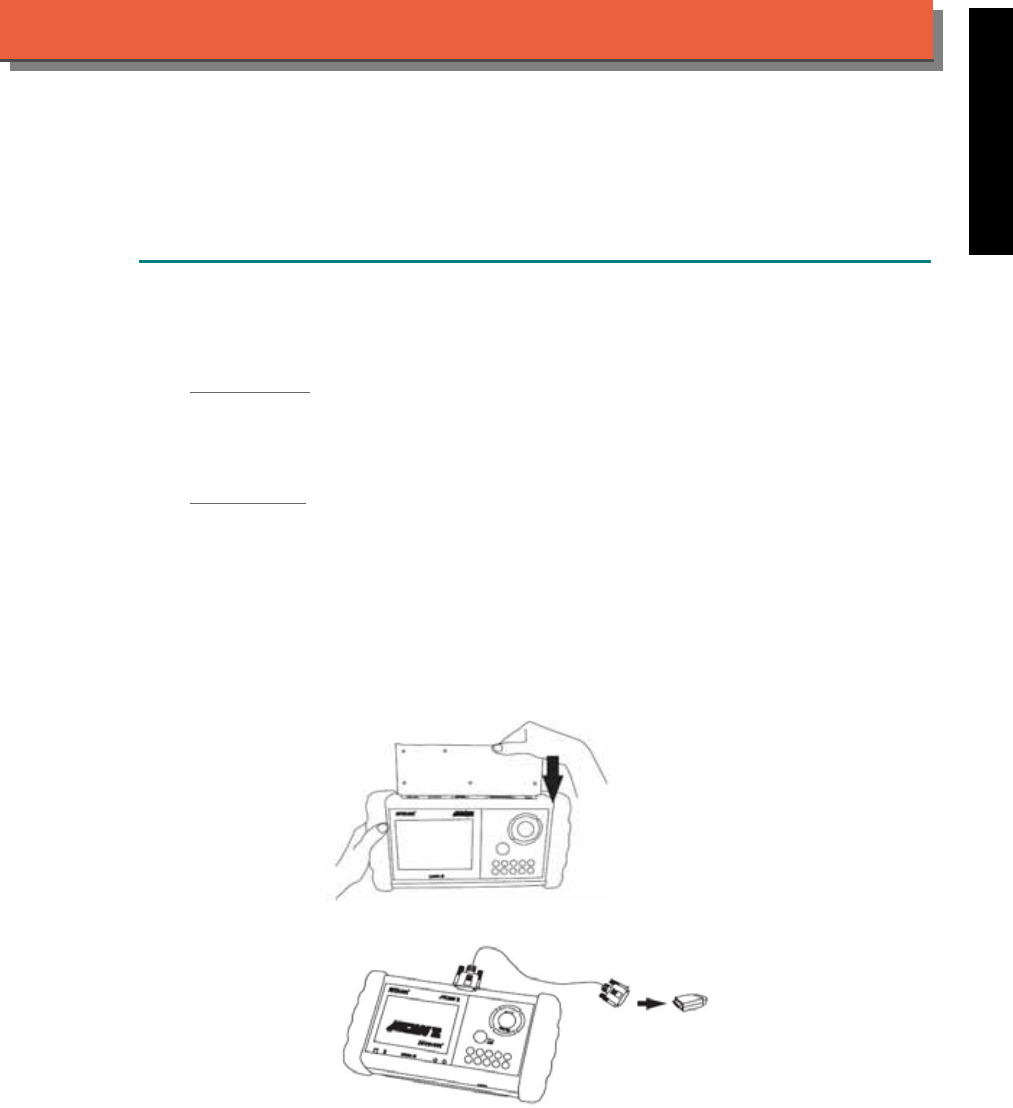
iSCAN-
II
Documentation
INFINITI
®
NISSAN
®
DIAGNOSTIC SYSTEM
GETTING STARTED
1. FIND THE DIAGNOSTIC SOCKET
There are two kinds of diagnostic sockets for INFINITI / NISSAN diagnostic system. Please note
that prior to the year 1998, most vehicles are equipped with 14-Pin socket.
OBD- II Socket
Most OBD-II diagnostic sockets are located under the steering wheel on driver side. For new
models after 2006, the communication protocol of ECUs is CAN. Please use OBDII-IM5 first on
new models, then try ASIAN-IM1 if the communication with some systems are failed.
14-PIN Soc ket
For the old models equipped with 14-PIN round socket, located in the fuse box under the
steering wheel on driver side. Some models might be equipped with OBD-II and 14-PIN
connectors together, only 14-PIN diagnostic socket can be worked.
2. SELECT THE INTERFACE MODULE
There are two interface modules available for INFINITI / NISSAN diagnostic system, OBDII-IM5
and ASIAN-IM1. Insert the interface module into the base unit firmly. Select the adapter that
corresponds to the socket, ex. OBDII-AC-16P.
iSCAN-II for INFINITI / NISSAN © 2008 Autoland Scientech. Page 1
AUT
LAND
®
SCIENTECH
INFINITI / NISSAN
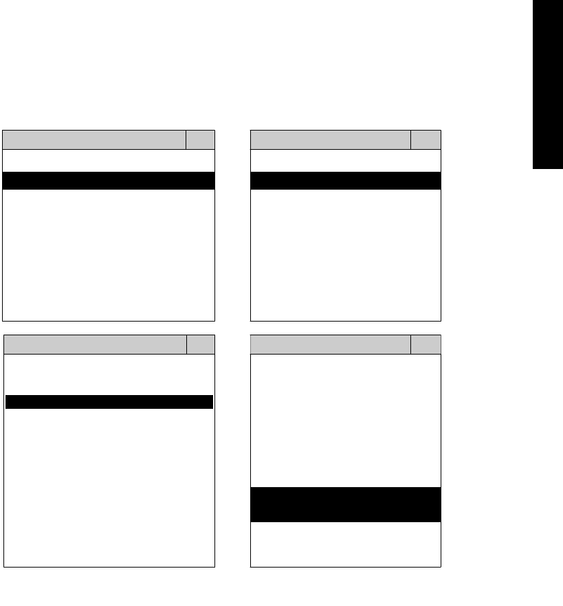
3. CONNECT TO THE VEHICLE
Plug the available diagnostic adapter into the diagnostic socket in the vehicles. Select the
INFINITI or NISSAN from the screen of iSCAN-II. Press ENTER to start the diagnostic
function. If the model is not listed on the screen, try to press RIGHT / LEFT buttons to turn the
page.
MAIN MENU
Vehicle Diagnostic
1 Vehicle Diagnostic 1 <ASIAN>
2 IMS
2
(Interface Module 2 <EUROPEAN>
Simulation System)
3 Component Test System
10 OBDII Standard Compliant
iSCAN-II (V1.00)
20 SETUP
<ASIAN>
<JAPAN>
1 <KOREA>
2 <JAPAN>
1 DAIHATSU NON-CAN
iSCAN-II (V1.00)
3 CHRYSLER
iSCAN-II (V1.00)
4 FORD OEM(OBDII 95~)
2 DAIHATSU CAN
iSCAN-II (V1.00)
3
HONDA
MAZDA OEM(OBDII 01~)
iSCAN-II (V1.00)
5. GM US
iSCAN-II (V1.00)
4 NISSAN
iSCAN-II (V1.00)
iSCAN-II (V1.00) 5 INFINITI
iSCAN-II (V1.00)
The figure is for reference only. Autoland Scientech updates the software very often. The
screen shown may not be the same as the newest software delivered.
iSCAN-II for INFINITI / NISSAN © 2008 Autoland Scientech. Page 2
INFINITI / NISSAN
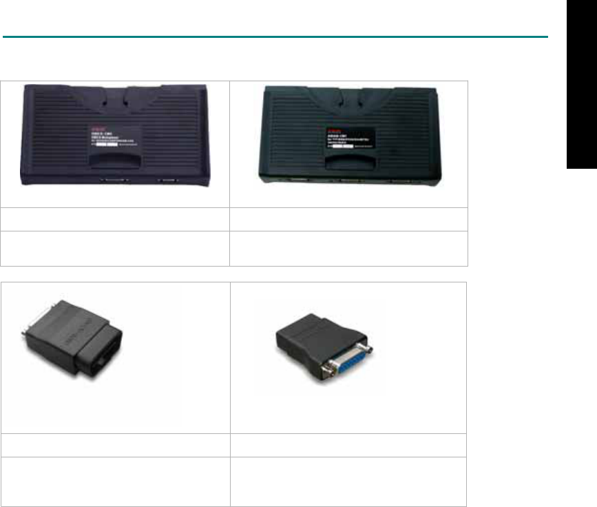
ADAPTERS AND INTERFACE MODULE
There are two interface modules available for the diagnostic system, OBDII-IM5 and ASIAN-IM1.
OBD
II
-IM5 ASIAN-IM1
OBD-II Full Specification Multiplexer ASIAN Interface Module for TOYOTA /
NISSAN / MITSUBISHI / HYUNDAI / KIA
OBD
II
-AC-16P NSN-AC-14P
The most common adapter for the new
models. Connect to the OBDII-IM5 or
ASIAN-IM1 with AC-EC1.
The adapter for the old models. Connect
to the ASIAN-IM1 with AC-EC1.
There are some adapters available. Refer to the “Diagnostic Cable Connection Quick Manual” for more
detailed connection / wiring information.
iSCAN-II for INFINITI / NISSAN © 2008 Autoland Scientech. Page 3
INFINITI / NISSAN
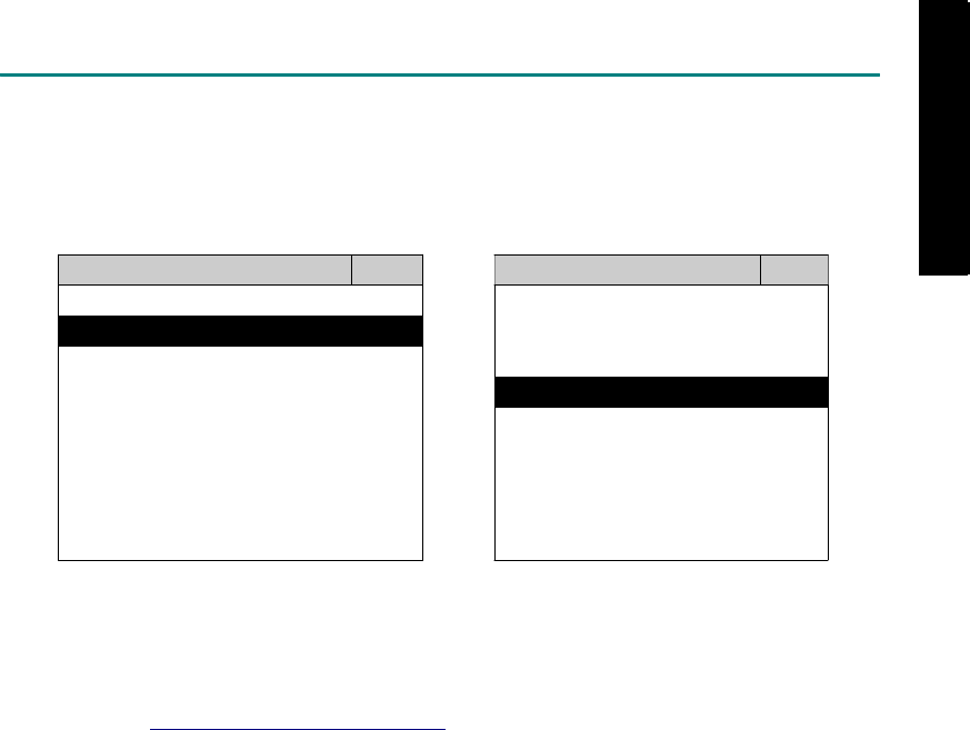
START TO DIAGNOSE
Select NISSAN or INFINITI by pressing the ENTER button. Turn ignition ON or make engine running at
idle. WARNING! Ignition ON without engine running may have a flat battery.
Select the system from the screen. There may be many systems on the vehicle, try to press RIGHT
button to turn the page. If the ECU response is successful, the screen will show all the available
functions.
INFINITI ENGINE
1 ENGINE 1 ID CODES
2 A/T 2 READ FAULT CODE
3 ABS / VST
4 SRS
5 EPS
3 CLEAR FAULT CODE
4 DATA STREAM
5 CLEAR ADAPTATION
6 2-PIN CODE LOOKUP 6 ECU RESET
The figure is for reference only. Autoland Scientech updates the software very often. The screen
shown may not be the same as the newest software delivered. We may simplify the steps of the
procedure.
Autoland Scientech will keep updating the diagnostic software for INFINITI / NISSAN. Please refer to
the software specification.
Visit our website, http://www.autolandscientech.com , and apply for membership. You will get E-paper
every month and find more diagnostic technical information.
iSCAN-II for INFINITI / NISSAN © 2008 Autoland Scientech. Page 4
INFINITI / NISSAN
INFINITI / NISSAN

TROUBLE SHOOTING
iSCAN-
II
never shows anything on LCD screen and there's no back-light?
1. Please check the cable and the connector again.
2. The voltage of the battery should be higher than 10V.
3. Check the power from OBD-II connector. PIN-16 is power, PIN-4 or PIN-5 is ground.
4. Check fuses in BU-EC (25-Pin Base Unit Extension Cable).
iSCAN-
II
never shows anything on LCD screen and the back-light is ON?
1. Check the diagnostic software using iSCAN-II/PSModule3 File Manager from PC. The
software for iSCAN-II may be missing or broken.
2. Adjust the brightness dial for the LCD panel. The brightness may be too dark.
Can't find the system on the screen?
1. Press Right button for more systems. There are too many systems which can't be shown
on the same page.
2. The diagnostic software does not have this system. Please refer to the specification. We
apologize for the inconvenience.
The green or yellow LED flashed on for a while, then showed 'CONNECTION FAILED'
on the LCD screen?
1. Make sure the ignition is ON or make the engine running at idle.
2. Ignition OFF for a while, then Ignition ON and try again.
3. Check the cable and the adapter. Unplug all cables and adapters and plug-in again.
4. Make sure the vehicle equips with the correct system. For example, the manual
transmission will not have A/T transmission ECU.
5. The vehicle will NOT equip with all the systems listed on the software. Some special
systems are only available on the luxury models.
6. The ECU is malfunction or the diagnostic line from the ECU is open or short to the ground or
power.
7. Battery voltage is too low.
Successfully connected to the system but shows 'VERSION UNKNOWN' on the LCD
screen?
Due to the prompt development of the Motor manufactures, the diagnostic software might not
be able to communicate with all ECU versions. Download the newest software from the member
area of Autoland Scientech website and try again. (http://www.autolandscientech.com)
If the same situation occurs, please report the information of ID pages to our local distributors.
We will keep updating the diagnostic software for new ECUs. Please excuse any inconvenience
this may cause.
Successfully connects to the system but shows 'LINK FAILURE' on the title?
Some ECUs are not as stable as our research department expected. Please report the
information of ID pages to our local distributors. Our R/D department will do our best to fix the
problems as soon as possible. Please excuse any inconvenience this may cause.
For models manufactured at 2006, which interface module should I insert?
Try OBDII-IM5 first, then ASIAN-IM1. OBDII-IM5 is applicable to CAN-protocol, and ASIAN-
IM1 is to INFINITI / NISSAN specific protocol. To connect with CAN-protocol models, ASIAN-
IM1 may send traditional signals to interrupt the inter-connection of the CAN-bus and cause
fault codes. Please use OBDII-IM5 with iSCAN-II INFINITI / NISSAN diagnostic software to
clear the fault codes.
Document Version 1.00 for iSCAN-II, © 2008 Autoland Scientech
The information contained herein is the exclusive property of Autoland Scientech
®
and shall not be distributed, reproduced, or disclosed
in whole or in part without prior written permission of Autoland Scientech
®
. Autoland Scientech
®
reserve the right to make any change
without notice. The trademarks mentioned belong to the owners.
iSCAN-II for INFINITI / NISSAN © 2008 Autoland Scientech. Page 5
INFINITI / NISSAN
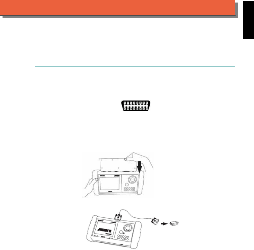
iSCAN-
II
Documentation
ISUZU
®
DIAGNOSTIC SYSTEM
GETTING STARTED
1. FIND THE DIAGNOSTIC SOCKET
OBD-
II Socket
The OBD-II diagnostic socket is located under the steering wheel on driver side.
OBD-
II
socket
2. SELECT THE INTERFACE MODULE
There is only one interface module available for ISUZU diagnostic system, OBDII-IM5. Insert
the interface module into the base unit firmly. Select the adapter that corresponds to the socket,
ex. OBDII-AC-16P.
iSCAN-II for ISUZU © 2008 Autoland Scientech. Page 1
AUT
LAND
®
SCIENTECH
ISUZU
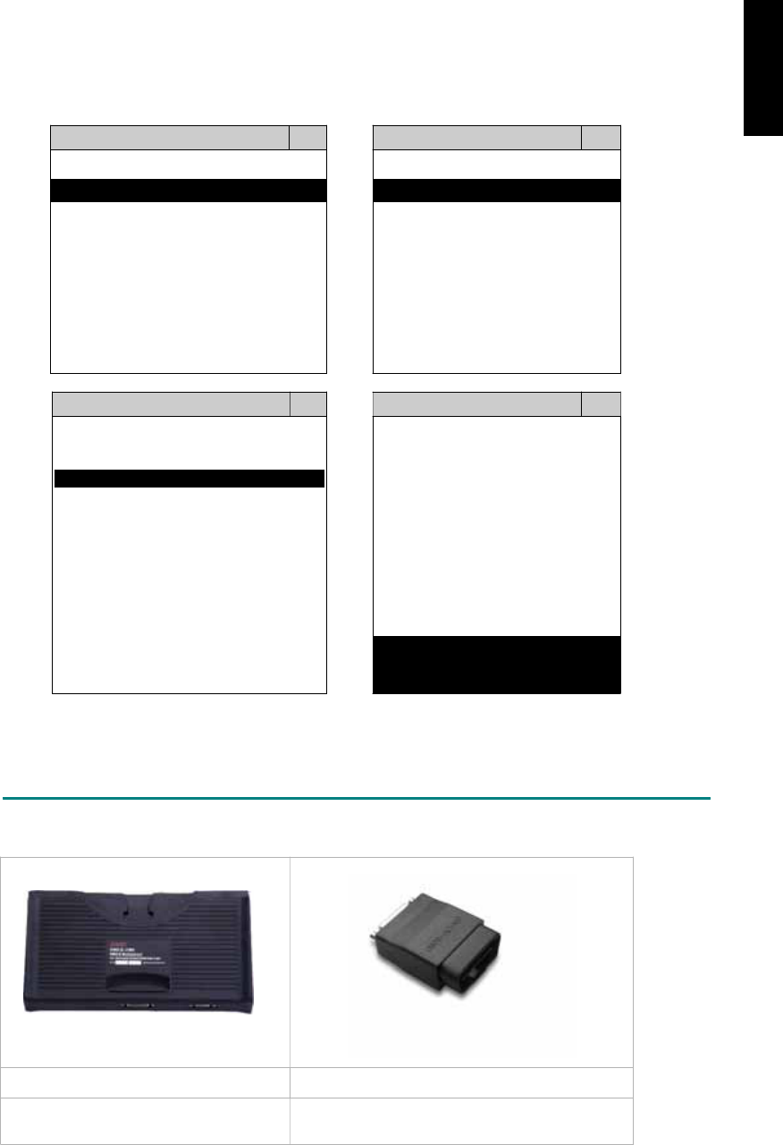
3. CONNECT TO THE VEHICLE
Plug the available diagnostic adapter into the diagnostic socket in the vehicle. Select the ISUZU
from the screen of iSCAN- II . Press ENTER to start the diagnostic function. If the model is not
listed on the screen, try to press RIGHT / LEFT buttons to turn the page.
MAIN MENU
Vehicle Diagnostic
1 Vehicle Diagnostic 1 <ASIAN>
2 IMS
2
(Interface Module 2 <EUROPEAN>
Simulation System)
3 Component Test System
10 OBDII Standard Compliant
iSCAN-II (V1.00)
20 SETUP
<ASIAN>
<JAPAN>
1 <KOREA>
2 <JAPAN>
1 DAIHATSU NON-CAN
iSCAN-II (V1.00)
3 CHRYSLER
iSCAN-II (V1.00)
4 FORD OEM(OBDII 95~)
2 DAIHATSU CAN
iSCAN-II (V1.00)
3
HONDA
MAZDA OEM(OBDII 01~)
iSCAN-II (V1.00)
5. GM US
iSCAN-II (V1.00)
4 ACURA
iSCAN-II (V1.00)
iSCAN-II (V1.00) 5 ISUZU
iSCAN-II (V1.00)
The figure is for reference only. Autoland Scientech updates the software very often. The
screen shown may not be the same as the newest software delivered.
ADAPTERS AND INTERFACE MODULE
There is only one interface module available for the diagnostic system, OBDII-IM5.
OBD
II
-IM5 OBD
II
-AC-16P
OBD-II Full Specification Multiplexer The most common adapter for the new models.
Connect to the OBDII-IM5 with AC-EC1.
There are some adapters available. Refer to the “Diagnostic Cable Connection Quick Manual” for more
detailed connection / wiring information.
iSCAN-II for ISUZU © 2008 Autoland Scientech. Page 2
ISUZU
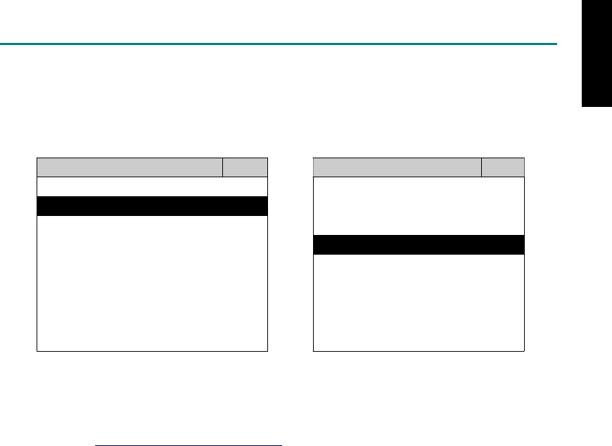
START TO DIAGNOSE
Select ISUZU by pressing the ENTER button. Turn ignition ON or make engine running at idle.
WARNING! Ignition ON without engine running may have a flat battery.
Select the system from the screen. There may be many systems on the vehicle, try to press RIGHT
button to turn the page. If the ECU response is successful, the screen will show all the available
functions.
ISUZU ENGINE
1 ENGINE 1 ID CODES
2 A/T 2 READ FAULT CODE
3 ABS
4 SRS
3 CLEAR FAULT CODE
4 DATA STREAM
The figure is for reference only. Autoland Scientech updates the software very often. The screen
shown may not be the same as the newest software delivered.
Autoland Scientech will keep updating the diagnostic software for ISUZU. Please refer to the software
specification.
Visit our website, http://www.autolandscientech.com , and apply for membership. You will get E-paper
every month and find more diagnostic technical information.
iSCAN-II for ISUZU © 2008 Autoland Scientech. Page 3
ISUZU

TROUBLE SHOOTING
iSCAN-
II
never show anything in LCD screen and no back-light?
1. Please check the cable and the connector again.
2. The voltage of the battery should be higher than 10V.
3. Check the power from OBD-II connector. PIN-16 is power, PIN-4 or PIN-5 is ground.
4. Check fuses in BU-EC (25-Pin Base Unit Extension Cable).
iSCAN-
II
never shows anything on LCD screen and the back-light is ON?
1. Check the diagnostic software using iSCAN-II/PSModule3 File Manager from PC. The
software for iSCAN-II may be missing or broken.
2. Adjust the brightness dial for the LCD panel. The brightness may be too dark.
Can't find the system on the screen?
1. Press Right button for more systems. There are too many systems which can't be shown
on the same page.
2. The diagnostic software does not have this system. Please refer to the specification. We
apologize for the inconvenience.
The green or yellow LED flashed on for a while, then showed 'CONNECTION FAILED'
on the LCD screen?
1. Make sure the ignition is ON or make the engine running at idle.
2. Ignition OFF for a while, then Ignition ON and try again.
3. Check the cable and the adapter. Unplug all cables and adapters and plug-in again.
4. Make sure the vehicle equips with the correct system. For example, the manual
transmission will not have A/T transmission ECU.
5. The vehicle will NOT equip with all the systems listed on the software. Some special
systems are only available on the luxury models.
6. The ECU is malfunction or the diagnostic line from the ECU is open or short to the ground or
power.
7. Battery voltage is too low.
Successfully connected to the system but shows 'VERSION UNKNOWN' on the LCD
screen?
Due to the prompt development of the Motor manufactures, the diagnostic software might not
be able to communicate with all ECU versions. Download the newest software from the member
area of Autoland Scientech website and try again. (http://www.autolandscientech.com)
If the same situation occurs, please report the information of ID pages to our local distributors.
We will keep updating the diagnostic software for new ECUs. Please excuse any inconvenience
this may cause.
Successfully connects to the system but shows 'LINK FAILURE' on the title?
Some ECUs are not as stable as our research department expected. Please report the
information of ID pages to our local distributors. Our R/D department will do our best to fix the
problems as soon as possible. Please excuse any inconvenience this may cause.
Document Version 1.00 for iSCAN-II, © 2008 Autoland Scientech
The information contained herein is the exclusive property of Autoland Scientech
®
and shall not be distributed, reproduced, or disclosed
in whole or in part without prior written permission of Autoland Scientech
®
. Autoland Scientech
®
reserve the right to make any change
without notice. The trademarks mentioned belong to the owners.
iSCAN-II for ISUZU © 2008 Autoland Scientech. Page 4
ISUZU
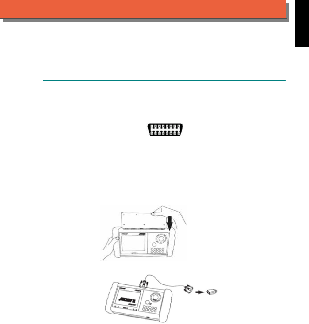
iSCAN-
II
Documentation
JAGUAR
®
DIAGNOSTIC SYSTEM
GETTING STARTED
1. FIND THE DIAGNOSTIC SOCKET
OBD-
II
Soc
ket
Most OBD-II diagnostic socket can be found under the dashboard on driver side and are
covered by a plastic cover.
OBD-
II
socket
Other Soc ket
iSCAN-II JAGUAR Diagnostic Software does not support the vehicles which are equipped with
the other sockets.
2. SELECT THE INTERFACE MODULE
There is only one interface module available for JAGUAR diagnostic system, OBDII-IM5. Insert
the interface module into the base unit firmly if the socket in the vehicle is OBD-II, and connect
the adapter that corresponds to the socket, OBDII-AC-16P.
iSCAN-II for JAGUAR © 2008 Autoland Scientech. Page 1
AUT
LAND
®
SCIENTECH
JAGUAR
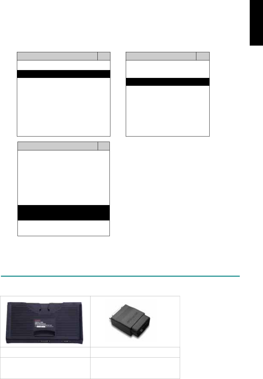
3. CONNECT TO THE VEHICLE
Plug the available diagnostic adapter into the diagnostic socket in the vehicle. Select the
JAGUAR from the screen of iSCAN-II . Press ENTER to start to diagnostic function. If the model
is not listed on the screen, try to press RIGHT / LEFT buttons to turn the page.
MAIN MENU
Vehicle Diagnostic
1 Vehicle Diagnostic 1 <ASIAN>
2 IMS
2
(Interface Module 2 <EUROPEAN>
Simulation System)
3 Component Test System
10 OBDII Standard Compliant
iSCAN-II(V1.00)
20 SETUP
<EUROPEAN>
1 <BMW GT2>
2 <FRENCH PKG>
3 MB
iSCAN-II (V1.00)
4. FIAT
iSCAN-II (V1.00)
5. JAGUAR
iSCAN-II (V1.00)
6. LANDROVER
iSCAN-II (V1.00)
The figure is for reference only. Autoland Scientech updates the software very often. The
screen shown may not be the same as the newest software delivered.
ADAPTERS AND INTERFACE MODULE
There is only one interface module available for the diagnostic system, OBDII-IM5.
OBD
II
-IM5 OBD
II
-AC-16P
Insert this interface module for the
models equipped with only OBD-II
socket.
The most common adapter for the
new models. Connect to the OBDII-
IM5 with AC-EC1.
There are some adapters available. Refer to the “Diagnostic Cable Connection Quick Manual” for more
detailed connection / wiring information.
iSCAN-II for JAGUAR © 2008 Autoland Scientech. Page 2
JAGUAR

START TO DIAGNOSE
Select JAGUAR by pressing the ENTER button. Turn ignition ON or make engine running at idle.
WARNING! Ignition ON without engine running may have a flat battery.
Select the system from the screen. There may be many systems on the vehicle, try to press RIGHT
button to turn the page. If the ECU response is successful, the screen will show all the available
functions.
JAGUAR TRANSMISSION
1 ENGINE 1 ID CODES
2 TRANSMISSION 2 READ FAULT CODE
3 ABS
4 SRS
3 CLEAR FAULT CODE
4 DATA STREAM
The figure is for reference only. Autoland Scientech updates the software very often. The screen
shown may not be the same as the newest software delivered. We may simplify the steps of the
procedure.
Autoland Scientech will keep updating the diagnostic software for JAGUAR. Please refer to the
software specification.
Visit our website, http://www.autolandscientech.com , and apply for membership. You will get E-paper
every month and find more diagnostic technical information.
iSCAN-II for JAGUAR © 2008 Autoland Scientech. Page 3
JAGUAR

TROUBLE SHOOTING
iSCAN-
II
never shows anything on LCD screen and there’s no back-light?
1. Please check the cable and the connector again.
2. The voltage of the battery should be higher than 10V.
3. Check the power from OBD-II connector. PIN-16 is power, PIN-4 or PIN-5 is ground.
4. Check fuses in BU-EC (25-Pin Base Unit Extension Cable).
iSCAN-
II
never shows anything on LCD screen and the back-light is ON?
1. Check the diagnostic software using iSCAN-II/PSModule3 File Manager from PC. The
software for iSCAN-II may be missing or broken.
2. Adjust the brightness dial for the LCD panel. The brightness may be too dark.
Can't find the system on the screen?
1. Press Right button for more systems. There are too many systems which can't be shown
on the same page.
2. The diagnostic software do not have this system. Please refer to the specification. We
apologize for the inconvenience.
The green or yellow LED flashed on for a while then showed 'CONNECTION FAILED'
on the LCD screen?
1. Make sure the ignition is ON or make the engine running at idle.
2. Ignition OFF for a while, then Ignition ON and try again.
3. Check the cable and the adapter. Unplug all cables and adapters and plug-in again.
4. Make sure the vehicle equips with the correct system. For example, the manual
transmission will not have A/T transmission ECU.
5. The vehicle will NOT equip with all the systems listed on the software. Some special
systems are only available on the luxury models.
6. The ECU is malfunction or the diagnostic line from the ECU is open or short to the ground or
power.
7. Battery voltage is too low.
Successfully connected to the system but shows 'VERSION UNKNOWN' on the LCD
screen?
Due to the prompt development of the Motor manufactures, the diagnostic software might not
be able to communicate with all ECU versions. Download the newest software from the member
area of Autoland Scientech website and try again. (http://www.autolandscientech.com)
If the same situation occurs, please report the information of ID pages to our local distributors.
We will keep updating the diagnostic software for new ECUs. Please excuse any inconvenience
this may cause.
Successfully connects to the system but show 'LINK FAILURE' on the title?
Some ECUs are not as stable as our research department expected. Please report the
information of ID pages to our local distributors. Our R/D department will do our best to fix the
problems as soon as possible. Please excuse any inconvenience this may cause.
Document Version 1.00 for iSCAN-II, © 2008 Autoland Scientech
The information contained herein is the exclusive property of Autoland Scientech
®
and shall not be distributed, reproduced, or disclosed
in whole or in part without prior written permission of Autoland Scientech
®
. Autoland Scientech
®
reserves the right to make any change
without notice. The trademarks mentioned belong to the owners.
iSCAN-II for JAGUAR © 2008 Autoland Scientech. Page 4
JAGUAR
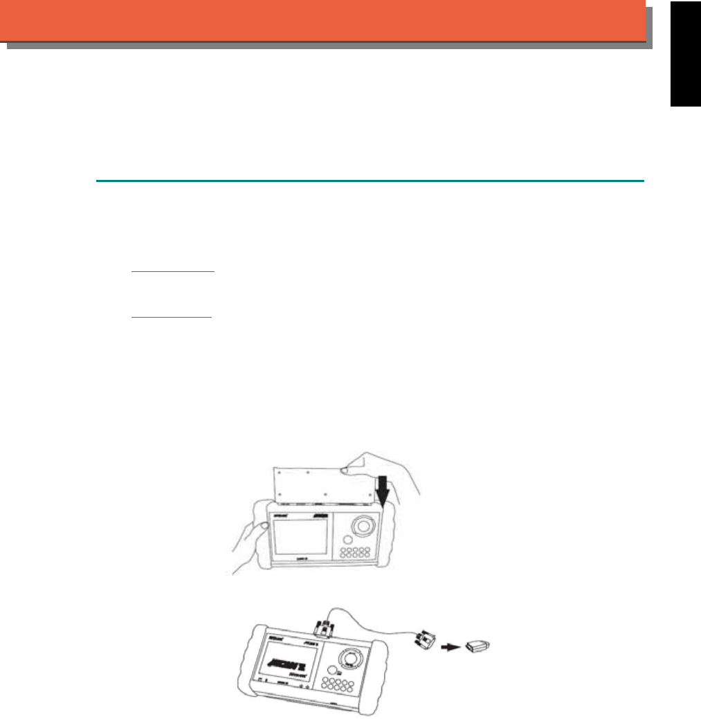
iSCAN-
II
Documentation
KIA
®
DIAGNOSTIC SYSTEM
GETTING STARTED
1. FIND THE DIAGNOSTIC SOCKET
There are two kinds of diagnostic sockets for KIA diagnostic system. Please note that prior to
the year 1998, most vehicles were equipped with 20-Pin socket.
OBD- II Socket
Most OBD-II diagnostic sockets are located under the steering wheel on driver side.
20-PIN Soc ket
For the old models equipped with 20-PIN socket, located in the engine compartment, beside the
driver side absorber strut tower or relay / fuse box.
2. SELECT THE INTERFACE MODULE
There are two interface modules available for KIA diagnostic system, OBDII-IM5 and ASIAN-
IM1. Insert the interface module into the base unit firmly. Select the adapter that corresponds to
the socket, ex. OBDII-AC-16P.
iSCAN-II for KIA © 2008 Autoland Scientech. Page 1
AUT
LAND
®
SCIENTECH
KIA
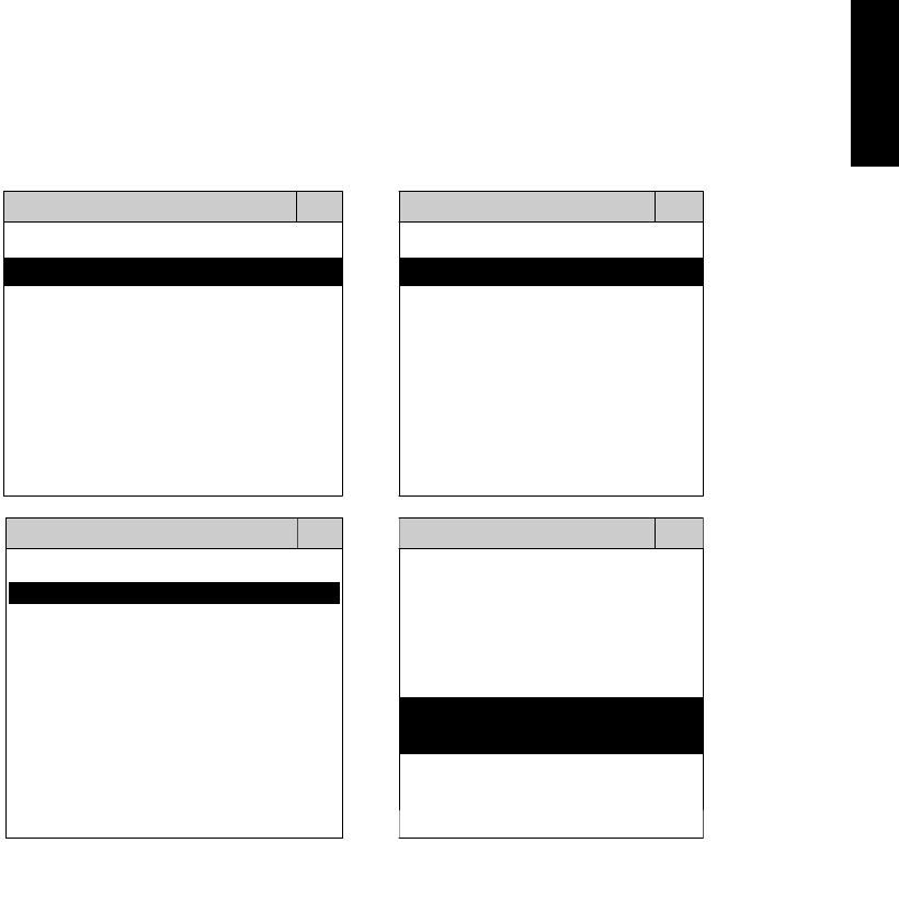
3. CONNECT TO THE VEHICLE
Plug the available diagnostic adapter into the diagnostic socket in the vehicles. Select the KIA
from the screen of iSCAN- II . Press ENTER to start the diagnostic function. If the model is not
listed on the screen, try to press RIGHT / LEFT buttons to turn the page.
MAIN MENU
Vehicle Diagnostic
1 Vehicle Diagnostic 1 <ASIAN>
2 IMS
2
(Interface Module 2 <EUROPEAN>
Simulation System)
3 Component Test System
10 OBDII Standard Compliant
iSCAN-II (V1.00)
20 SETUP
<ASIAN>
<KOREA>
1 <KOREA>
2 <JAPAN>
1 DAEWOO
iSCAN-II (V1.00)
3 CHRYSLER
iSCAN-II (V1.00)
4 FORD OEM(OBDII 95~)
2 HYUNDAI
iSCAN-II (V1.00)
3 KIA
MAZDA OEM(OBDII 01~)
iSCAN-II (V1.00)
5. GM US
iSCAN-II (V1.00)
4 SSANGYONG
iSCAN-II (V1.00)
iSCAN-II (V1.00)
The figure is for reference only. Autoland Scientech updates the software very often. The
screen shown may not be the same as the newest software delivered.
iSCAN-II for KIA © 2008 Autoland Scientech. Page 2
KIA
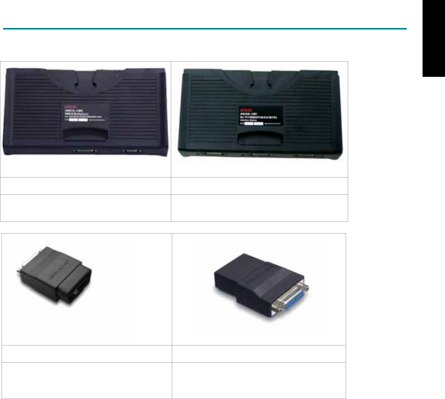
ADAPTERS AND INTERFACE MODULE
There are two interface modules available for the diagnostic system, OBDII-IM5 and ASIAN-IM1.
OBD
II
-IM5 ASIAN-IM1
OBDII-IM5 is for CAN-BUS protocol
only.
Select ASIAN-IM1 with MIT port first.
OBD
II
-AC-16P KIA-AC-20P
The most common adapter for the new
models. Connect to the OBDII-IM5 or
ASIAN-IM1 with AC-EC1.
The adapter for the old models. Connect
to ASIAN-IM1 with AC-EC1.
There are some adapters available. Refer to the “Diagnostic Cable Connection Quick Manual” for more
detailed connection / wiring information.
iSCAN-II for KIA © 2008 Autoland Scientech. Page 3
KIA
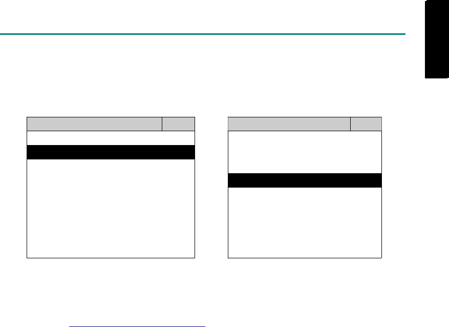
START TO DIAGNOSE
Select KIA by pressing the ENTER button. Turn ignition ON or make engine running at idle.
WARNING! Ignition ON without engine running may have a flat battery.
Select the system from the screen. There may be many systems on the vehicle, try to press RIGHT
button to turn the page. If the ECU response is successful, the screen will show all the available
functions.
KIA ENGINE
1 ENGINE 1 ID CODES
2 A/T 2 READ FAULT CODE
3 ABS
4 SRS
3 CLEAR FAULT CODE
4 DATA STREAM
The figure is for reference only. Autoland Scientech updates the software very often. The screen
shown may not be the same as the newest software delivered.
Autoland Scientech will keep updating the diagnostic software for KIA. Please refer to the software
specification.
Visit our website, http://www.autolandscientech.com , and apply for membership. You will get E-paper
every month and find more diagnostic technical information.
iSCAN-II for KIA © 2008 Autoland Scientech. Page 4
KIA
KIA

TROUBLE SHOOTING
iSCAN-
II
never shows anything on LCD screen and there's no back-light?
1. Please check the cable and the connector again.
2. The voltage of the battery should be higher than 10V.
3. Check the power from OBD-II connector. PIN-16 is power, PIN-4 or PIN-5 is ground.
4. Check fuses in BU-EC (25-Pin Base Unit Extension Cable).
iSCAN-
II
never shows anything on LCD screen and the back-light is ON?
1. Check the diagnostic software using iSCAN-II/PSModule3 File Manager from PC. The
software for iSCAN-II may be missing or broken.
2. Adjust the brightness dial for the LCD panel. The brightness may be too dark.
Can't find the system on the screen?
1. Press Right button for more systems. There are too many systems which can't be shown
on the same page.
2. The diagnostic software does not have this system. Please refer to the specification. We
apologize for the inconvenience.
The green or yellow LED flashed on for a while, then showed 'CONNECTION FAILED'
on the LCD screen?
1. Make sure the ignition is ON or make the engine running at idle.
2. Ignition OFF for a while, then Ignition ON and try again.
3. Check the cable and the adapter. Unplug all cables and adapters and plug-in again.
4. Make sure the vehicle equips with the correct system. For example, the manual
transmission will not have A/T transmission ECU.
5. The vehicle will NOT equip with all the systems listed on the software. Some special
systems are only available on the luxury models.
6. The ECU is malfunction or the diagnostic line from the ECU is open or short to the ground or
power.
7. Battery voltage is too low.
Successfully connected to the system but shows 'VERSION UNKNOWN' on the LCD
screen?
Due to the prompt development of the Motor manufactures, the diagnostic software might not
be able to communicate with all ECU versions. Download the newest software from the member
area of Autoland Scientech website and try again. (http://www.autolandscientech.com)
If the same situation occurs, please report the information of ID pages to our local distributors.
We will keep updating the diagnostic software for new ECUs. Please excuse any inconvenience
this may cause.
Successfully connects to the system but shows 'LINK FAILURE' on the title?
Some ECUs are not as stable as our research department expected. Please report the
information of ID pages to our local distributors. Our R/D department will do our best to fix the
problems as soon as possible. Please excuse any inconvenience this may cause.
For models manufactured at 2006, which interface module should I insert?
Try OBDII-IM5 first, then ASIAN-IM1. OBDII-IM5 is applicable to CAN-protocol, and ASIAN-
IM1 is to KIA specific protocol. To connect with CAN-protocol models, ASIAN-IM1 may send
traditional signals to interrupt the inter-connection of the CAN-bus and cause fault codes.
Please use iSCAN-II KIA diagnostic software to clear the fault code.
Document Version 1.00 for iSCAN-II, © 2008 Autoland Scientech
The information contained herein is the exclusive property of Autoland Scientech
®
and shall not be distributed, reproduced, or disclosed
in whole or in part without prior written permission of Autoland Scientech
®
. Autoland Scientech
®
reserve the right to make any change
without notice. The trademarks mentioned belong to the owners.
iSCAN-II for KIA © 2008 Autoland Scientech. Page 5
KIA

iSCAN-
II
Documentation
LANDROVER
®
DIAGNOSTIC SYSTEM
GETTING STARTED
1. FIND THE DIAGNOSTIC SOCKET
OBD-
II
Soc
ket
Most OBD-II diagnostic socket can be found under the dashboard on driver side and are
covered by a plastic cover.
OBD-
II
socket
Other Soc ket
iSCAN-II LANDROVER Diagnostic Software does not support the vehicles which are equipped
with the other sockets.
2. SELECT THE INTERFACE MODULE
There is only one interface module available for LANDROVER diagnostic system, OBDII-IM5.
Insert the interface module into the base unit firmly if the socket in the vehicle is OBDII, and
connect the adapter that corresponds to the socket, OBDII-AC-16P.
iSCAN-II for LANDROVER © 2008 Autoland Scientech. Page 1
AUT
LAND
®
SCIENTECH
LANDROVER
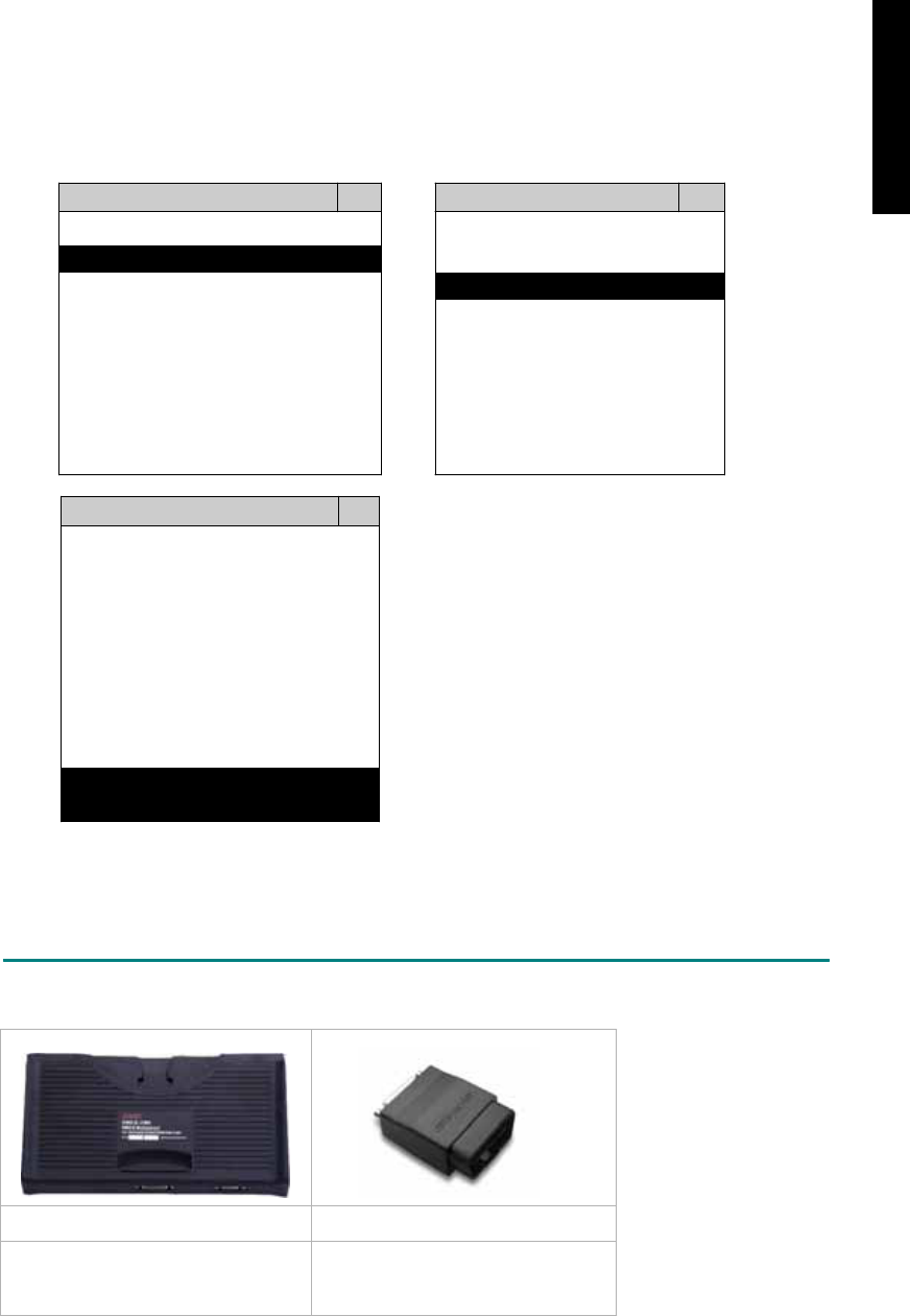
3. CONNECT TO THE VEHICLE
Plug the available diagnostic adapter into the diagnostic socket in the vehicle. Select the
LANDROVER from the screen of iSCAN-II . Press ENTER to start to diagnostic function. If the
model is not listed on the screen, try to press RIGHT / LEFT buttons to turn the page.
MAIN MENU
Vehicle Diagnostic
1 Vehicle Diagnostic 1 <ASIAN>
2 IMS
2
(Interface Module 2 <EUROPEAN>
Simulation System)
3 Component Test System
10 OBDII Standard Compliant
iSCAN-II(V1.00)
20 SETUP
<EUROPEAN>
1 <BMW GT2>
2 <FRENCH PKG>
3 MB
iSCAN-II (V1.00)
4. FIAT
iSCAN-II (V1.00)
5. JAGUAR
iSCAN-II (V1.00)
6. LANDROVER
iSCAN-II (V1.00)
The figure is for reference only. Autoland Scientech updates the software very often. The
screen shown may not be the same as the newest software delivered.
ADAPTERS AND INTERFACE MODULE
There is only one interface module available for the diagnostic system, OBDII-IM5.
OBD
II
-IM5 OBD
II
-AC-16P
Insert this interface module for the
models equipped with only OBD-II
socket.
The most common adapter for the
new models. Connect to the OBDII-
IM5 with AC-EC1.
There are some adapters available. Refer to the “Diagnostic Cable Connection Quick Manual” for more
detailed connection / wiring information.
iSCAN-II for LANDROVER © 2008 Autoland Scientech. Page 2
LANDROVER
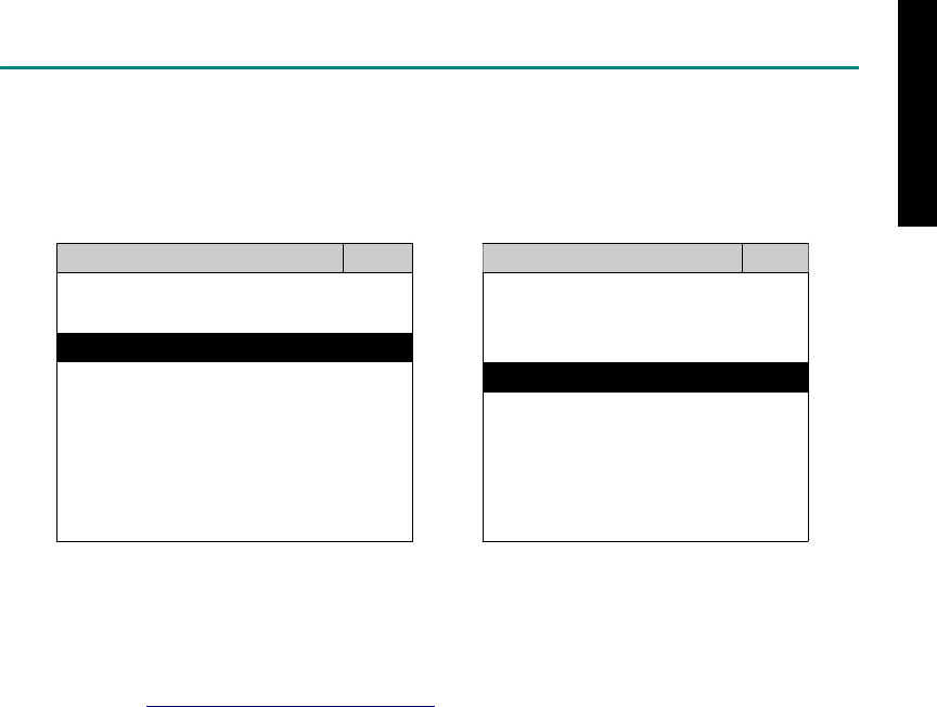
START TO DIAGNOSE
Select LANDROVER by pressing the ENTER button. Turn ignition ON or make engine running at idle.
WARNING! Ignition ON without engine running may have a flat battery.
Select the system from the screen. There may be many systems on the vehicle, try to press RIGHT
button to turn the page. If the ECU response is successful, the screen will show all the available
functions.
LANDROVER TRANSMISSION
1 ENGINE 1 ID CODES
2 TRANSMISSION 2 READ FAULT CODE
3 ABS
4 SRS
3 CLEAR FAULT CODE
4 DATA STREAM
The figure is for reference only. Autoland Scientech updates the software very often. The screen
shown may not be the same as the newest software delivered. We may simplify the steps of the
procedure.
Autoland Scientech will keep updating the diagnostic software for LANDROVER. Please refer to the
software specification.
Visit our website, http://www.autolandscientech.com , and apply for membership. You will get E-paper
every month and find more diagnostic technical information.
iSCAN-II for LANDROVER © 2008 Autoland Scientech. Page 3
LANDROVER

TROUBLE SHOOTING
iSCAN-
II
never shows anything on LCD screen and there’s no back-light?
1. Please check the cable and the connector again.
2. The voltage of the battery should be higher than 10V.
3. Check the power from OBD-II connector. PIN-16 is power, PIN-4 or PIN-5 is ground.
4. Check fuses in BU-EC (25-Pin Base Unit Extension Cable).
iSCAN-
II
never shows anything on LCD screen and the back-light is ON?
1. Check the diagnostic software using iSCAN-II/PSModule3 File Manager from PC. The
software for iSCAN-II may be missing or broken.
2. Adjust the brightness dial for the LCD panel. The brightness may be too dark.
Can't find the system on the screen?
1. Press Right button for more systems. There are too many systems which can't be shown
on the same page.
2. The diagnostic software does not have this system. Please refer to the specification. We
apologize for the inconvenience.
The green or yellow LED flashed on for a while then showed 'CONNECTION FAILED'
on the LCD screen?
1. Make sure the ignition is ON or make the engine running at idle.
2. Ignition OFF for a while, then Ignition ON and try again.
3. Check the cable and the adapter. Unplug all cables and adapters and plug-in again.
4. Make sure the vehicle equips with the correct system. For example, the manual
transmission will not have A/T transmission ECU.
5. The vehicle will NOT equip with all the systems listed on the software. Some special
systems are only available on the luxury models.
6. The ECU is malfunction or the diagnostic line from the ECU is open or short to the ground or
power.
7. Battery voltage is too low.
Successfully connects to the system but shows 'VERSION UNKNOWN' on the LCD
screen?
Due to the prompt development of the Motor manufactures, the diagnostic software might not
be able to communicate with all ECU versions. Download the newest software from the member
area of Autoland Scientech website and try again. (http://www.autolandscientech.com)
If the same situation occurs, please report the information of ID pages to our local distributors.
We will keep updating the diagnostic software for new ECUs. Please excuse any inconvenience
this may cause.
Successfully connect to the system but show 'LINK FAILURE' on the title?
Some ECUs are not as stable as our research department expected. Please report the
information of ID pages to our local distributors. Our R/D department will do our best to fix the
problems as soon as possible. Please excuse any inconvenience this may cause.
Document Version 1.00 for iSCAN-II, © 2008 Autoland Scientech
The information contained herein is the exclusive property of Autoland Scientech
®
and shall not be distributed, reproduced, or disclosed
in whole or in part without prior written permission of Autoland Scientech
®
. Autoland Scientech
®
reserves the right to make any change
without notice. The trademarks mentioned belong to the owners.
iSCAN-II for LANDROVER © 2008 Autoland Scientech. Page 4
LANDROVER
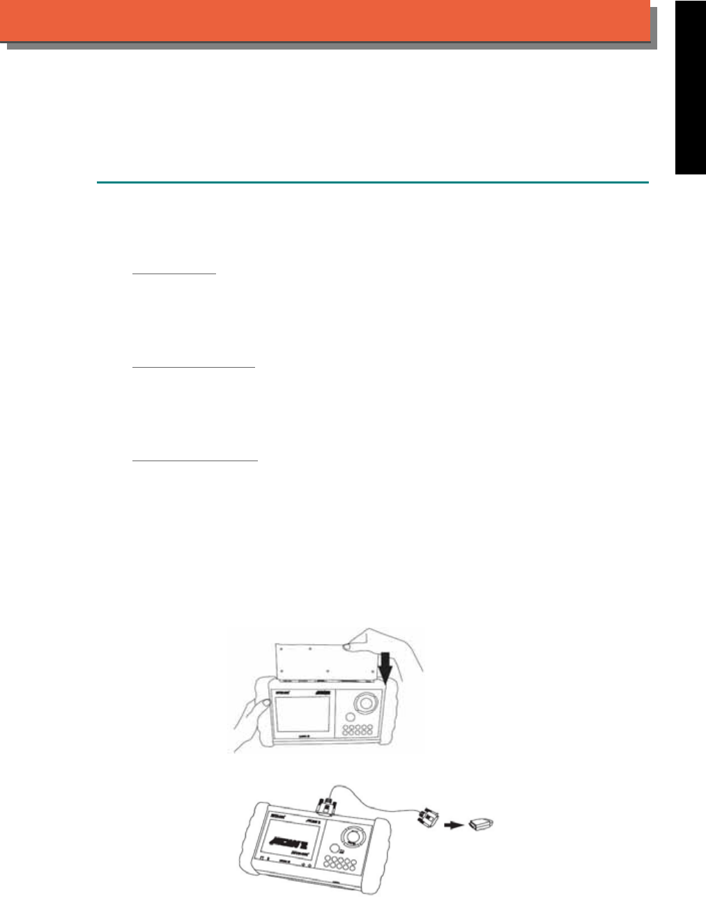
iSCAN-
II
Documentation
LEXUS
®
TOYOTA
®
DIAGNOSTIC SYSTEM
GETTING STARTED
1. FIND THE DIAGNOSTIC SOCKET
There are three kinds of diagnostic sockets for LEXUS / TOYOTA. Please note that prior to the
year 1998, most vehicles are equipped with 17-Pin round socket or 23-Pin square socket.
OBD- II Socket
Most OBD-II diagnostic sockets are located under the steering wheel on driver side. The
connector of some models can be found behind the coin box / ashtray box. For new models
after 2006, the communication protocol of ECUs is CAN. Please use OBDII-IM5 first on new
models, then try ASIAN-IM1 if the communication with some systems are failed.
17-PIN Round Soc ket
For the older models equipped with 17-PIN round socket, located under the steering wheel on
driver side. Some models might be equipped with OBD-II and 17-PIN connectors together. Try
both connectors for each system. For these models, only ASIAN-IM1 interface module is
available.
23-PIN Square Soc ket
For the old models which equipped with 23-PIN square socket, located in the engine
compartment, beside driver side or passenger side absorber strut tower. Some models might be
equipped with OBD-II, 17-PIN, 23-PIN connectors together. Try all connectors for each system.
For those models, only ASIAN-IM1 interface module is available.
2. SELECT THE INTERFACE MODULE
There are two interface modules available for LEXUS / TOYOTA diagnostic system, OBDII-IM5
and ASIAN-IM1. Insert the interface module into the base unit firmly. Select the adapter that
corresponds to the socket, ex. OBDII-AC-16P.
iSCAN-II for LEXUS / TOYOTA © 2008 Autoland Scientech. Page 1
AUT
LAND
®
SCIENTECH
LEXUS / TOYOTA
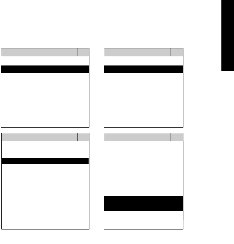
3. CONNECT TO THE VEHICLE
Plug the available diagnostic adapter into the diangostic socket in the vehicles. Select the
LEXUS or TOYOTA from the screen of iSCAN-II. Press ENTER to start the diagnostic function.
If the model is not listed on the screen, try to press RIGHT / LEFT buttons to turn the page.
MAIN MENU
Vehicle Diagnostic
1 Vehicle Diagnostic 1 <ASIAN>
2 IMS
2
(Interface Module 2 <EUROPEAN>
Simulation System)
3 Component Test System
10 OBDII Standard Compliant
iSCAN-II (V1.00)
20 SETUP
<ASIAN>
<JAPAN>
1 <KOREA>
2 <JAPAN>
1 DAIHATSU NON-CAN
iSCAN-II (V1.00)
3 CHRYSLER
iSCAN-II (V1.00)
4 FORD OEM(OBDII 95~)
2 DAIHATSU CAN
iSCAN-II (V1.00)
3
HONDA
MAZDA OEM(OBDII 01~)
iSCAN-II (V1.00)
5. GM US
iSCAN-II (V1.00)
4 TOYOTA
iSCAN-II (V1.00)
iSCAN-II (V1.00) 5 LEXUS
iSCAN-II (V1.00)
The figure is for reference only. Autoland Scientech updates the software very often. The
screen shown may not be the same as the newest software delivered.
iSCAN-II for LEXUS / TOYOTA © 2008 Autoland Scientech. Page 2
LEXUS / TOYOTA
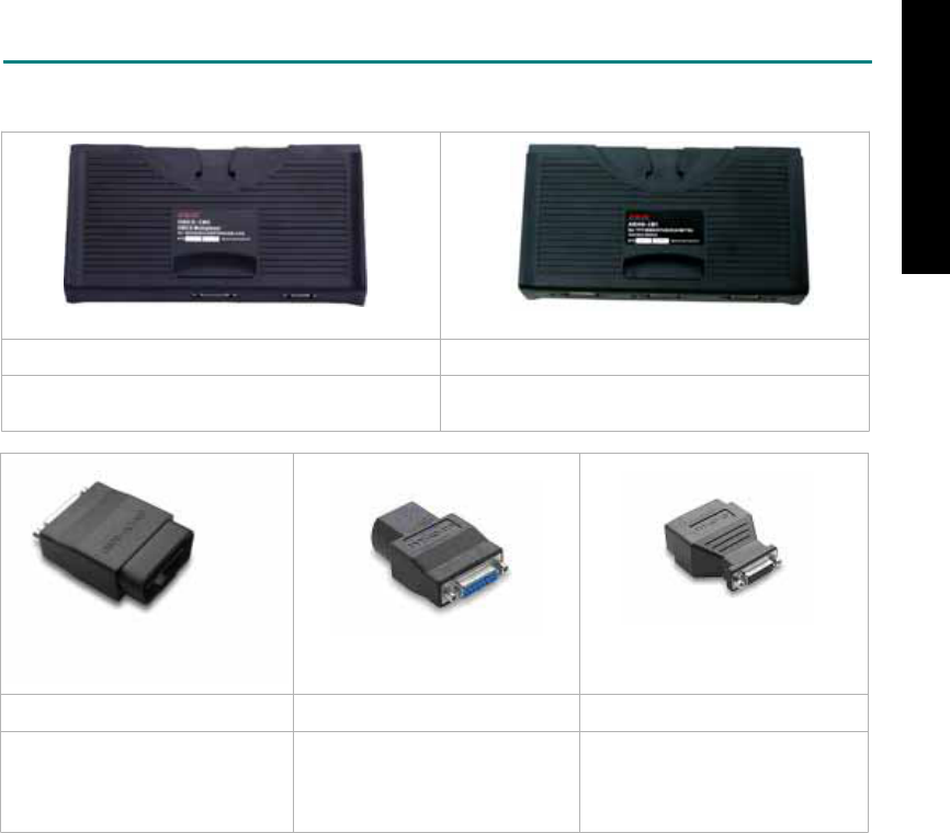
ADAPTERS AND INTERFACE MODULE
There are two interface modules available for the diagnostic system, OBDII-IM5 and ASIAN-IM1.
OBDII-IM5 ASIAN-IM1
OBD-II Full Specification Multiplexer ASIAN Interface Module for TOYOTA / NISSAN /
MITSUBISHI / HYUNDAI / KIA
OBD
II
-AC-16P TYT-AC-17P TYT-AC-23P
The most common adapter for
the new models. Connect to the
OBDII-IM5 or ASIAN-IM1 with
AC-EC1.
The adapter for the old models.
Connect to the ASIAN-IM1 with
AC-EC1
.
The adapter for the oldest
models. Connect to the ASIAN-
IM1 with AC-EC1.
There are some adapters available. Refer to the “Diagnostic Cable Connection Quick Manual” for more
detailed connection / wiring information.
iSCAN-II for LEXUS / TOYOTA © 2008 Autoland Scientech. Page 3
LEXUS / TOYOTA

START TO DIAGNOSE
Select TOYOTA / LEXUS by pressing the ENTER button. Turn ignition ON or make engine running at
idle. WARNING! Ignition ON without engine running may have a flat battery.
Select the system from the screen. There may be many systems on the vehicle, try to press RIGHT
button to turn the page. If the ECU response is successful, the screen will show all the available
functions.
LEXUS ENGINE
1 ENGINE 1 ID CODES
2 A/T 2 READ FAULT CODE
3 ABS / VST
4 SRS
5 EPS
3 CLEAR FAULT CODE
4 DATA STREAM
5 CLEAR ADAPTATION
6 2-PIN CODE LOOKUP 6 ECU RESET
The figure is for reference only. Autoland Scientech updates the software very often. The screen
shown may not be the same as the newest software delivered. We may simplify the steps of the
procedure.
Autoland Scientech will keep updating the diagnostic software for TOYOTA / LEXUS. Please refer to
the software specification.
Visit our website, http://www.autolandscientech.com , and apply for membership. You will get E-paper
every month and find more diagnostic technical information.
iSCAN-II for LEXUS / TOYOTA © 2008 Autoland Scientech. Page 4
LEXUS / TOYOTA
LEXUS / TOYOTA

TROUBLE SHOOTING
iSCAN-
II
never shows anything on LCD screen and there's no back-light?
1. Please check the cable and the connector again.
2. The voltage of the battery should be higher than 10V.
3. Check the power from OBD-II connector. PIN-16 is power, PIN-4 or PIN-5 is ground.
4. Check fuses in BU-EC (25-Pin Base Unit Extension Cable).
iSCAN-
II
never shows anything on LCD screen and the back-light is ON?
1. Check the diagnostic software using iSCAN-II/PSModule3 File Manager from PC. The
software for iSCAN-II may be missing or broken.
2. Adjust the brightness dial for the LCD panel. The brightness may be too dark.
Can't find the system on the screen?
1. Press Right button for more systems. There are too many systems which can't be shown
on the same page.
2. The diagnostic software does not have this system. Please refer to the specification. We
apologize for the inconvenience.
The green or yellow LED flashed on for a while, then showed 'CONNECTION FAILED'
on the LCD screen?
1. Make sure the ignition is ON or make the engine running at idle.
2. Ignition OFF for a while, then Ignition ON and try again.
3. Check the cable and the adapter. Unplug all cables and adapters and plug-in again.
4. Make sure the vehicle equips with the correct system. For example, the manual
transmission will not have A/T transmission ECU.
5. The vehicle will NOT equip with all the systems listed on the software. Some special
systems are only available on the luxury models.
6. The ECU is malfunction or the diagnostic line from the ECU is open or short to the ground or
power.
7. Battery voltage is too low.
Successfully connected to the system but shows 'VERSION UNKNOWN' on the LCD
screen?
Due to the prompt development of the Motor manufactures, the diagnostic software might not
be able to communicate with all ECU versions. Download the newest software from the member
area of Autoland Scientech website and try again. (http://www.autolandscientech.com)
If the same situation occurs, please report the information of ID pages to our local distributors.
We will keep updating the diagnostic software for new ECUs. Please excuse any inconvenience
this may cause.
Successfully connects to the system but shows 'LINK FAILURE' on the title?
Some ECUs are not as stable as our research department expected. Please report the
information of ID pages to our local distributors. Our R/D department will do our best to fix the
problems as soon as possible. Please excuse any inconvenience this may cause.
For models manufactured at 2006, which interface module should I insert?
Try OBDII-IM5 first, then ASIAN-IM1. OBDII-IM5 is applicable to CAN-protocol, and ASIAN-
IM1 is to LEXUS / TOYOTA specific protocol. To connect with CAN-protocol models, ASIAN-IM1
may send traditional signals to interrupt the inter-connection of the CAN-bus and cause fault
codes. Please use OBDII-IM5 with iSCAN-II LEXUS / TOYOTA diagnostic software to clear the
fault codes.
Document Version 1.00 for iSCAN-II, © 2008 Autoland Scientech
The information contained herein is the exclusive property of Autoland Scientech
®
and shall not be distributed, reproduced, or disclosed
in whole or in part without prior written permission of Autoland Scientech
®
. Autoland Scientech
®
reserve the right to make any change
without notice. The trademarks mentioned belong to the owners.
iSCAN-II for LEXUS / TOYOTA © 2008 Autoland Scientech. Page 5
LEXUS / TOYOTA
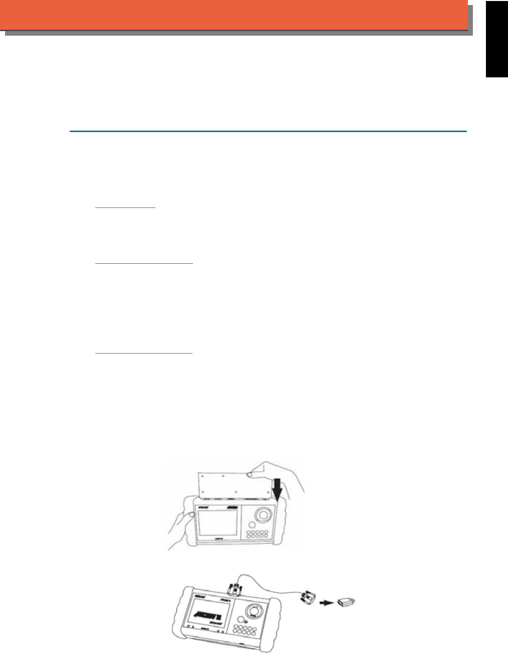
iSCAN-
II
Documentation
MAZDA
®
DIAGNOSTIC SYSTEM
GETTING STARTED
1. FIND THE DIAGNOSTIC SOCKET
Mazda is a partial subsidiary of Ford Motor Company. The Mazda software only covers on old
cars with old sockets, ex. 17+8 pin, 6+1 pin and 20-pin. For new Mazda, please select iSCAN-II
FORD Diagnostic Software.
OBD- II Socket
IF YOU FIND OBDII SOCKET, PLEASE SELECT iSCAN-II FORD DIAGNOSTIC SOFTWARE.
Most OBD-II diagnostic sockets are located under the steering wheel on driver side. The
connector can be found behind the coin box / ashtray box for some models..
17+8 PIN Round Soc ket
For the old models which were not equipped with OBD-II socket, there is a 17+8 PIN round
socket available. Most the 17-PIN round sockets are located under the steering wheel on driver
side. The diagnostic socket in some models are located in the engine compartment, beside the
driver side or passenger side absorber strut tower. Some models will equip with OBD-II and 17-
PIN connectors together, but only 17+8 PIN socket can be worked. For these models, only
ASIAN-IM1 interface module is available.
6+1 PIN / 20-PIN Soc ket
The diagnostic socket is located in the engine compartment, beside the driver side or passenger
side absorber strut tower. Connect the diagnostic socket to the base unit with BU-EC cable. The
pin location will be shown on the screen of iSCAN-II.
2. SELECT THE INTERFACE MODULE
There is only one interface module available for Mazda diagnostic system, ASIAN-IM1. Insert
the interface module into the base unit firmly IF THERE IS A 17+8 PIN SOCKET IS FOUND,
connect to TYT-connector. For 6+1 pin and 20-pin socket, connect directly with BU-EC cable.
iSCAN-II for MAZDA © 2008 Autoland Scientech. Page 1
AUT
LAND
®
SCIENTECH
MAZDA
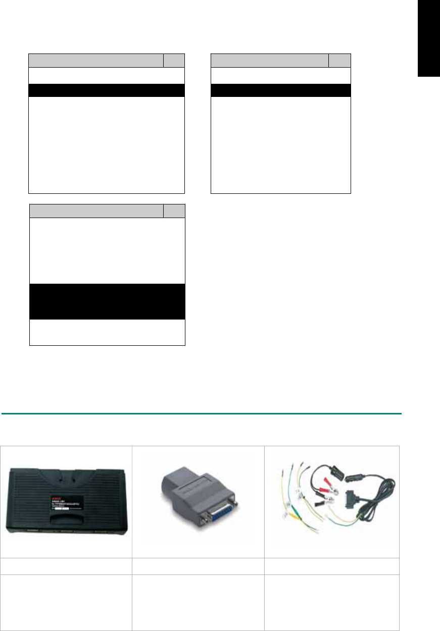
3. CONNECT TO THE VEHICLE
Plug the available diagnostic adapter into the diagnostic socket in the vehicle. Select the
MAZDA from the screen of iSCAN-II. Press ENTER to start the diagnostic function. If the
model is not listed on the screen, try to press RIGHT / LEFT buttons to turn the page.
MAIN MENU
Vehicle Diagnostic
1 Vehicle Diagnostic 1 <ASIAN>
2 IMS
2
(Interface Module 2 <EUROPEAN>
Simulation System)
3 Component Test System
10 OBDII Standard Compliant
iSCAN-II (V1.00)
20 SETUP
<ASIAN>
1 <KOREA>
2 <JAPAN>
3 CHRYSLER
iSCAN-II (V1.00)
4 FORD OEM(OBDII 95~)
MAZDA OEM(OBDII 01~)
iSCAN-II (V1.00)
5. GM US
iSCAN-II (V1.00)
The figure is for reference only. Autoland Scientech updates the software very often. The
screen shown may not be the same as the newest software delivered.
ADAPTERS AND INTERFACE MODULE
There is only one interface module available for the diagnostic system, ASIAN-IM1.
ASIAN-IM1 MAZ-AC-17P D51-C1-2P-MAZ
For 17+8 PIN socket For 17+8 connector. BE
CAREFUL!! TYT-AC-17P is
almost the same as MAZ-AC-
17P and it will NOT work for
Mazda vehicle.
The adapter for the old models
equipped with 6+1/20 pin socket.
Connect directly to the base unit
with BC-EC.
There are some adapters available. Refer to the “Diagnostic Cable Connection Quick Manual” for more
detailed connection / wiring information.
iSCAN-II for MAZDA © 2008 Autoland Scientech. Page 2
MAZDA
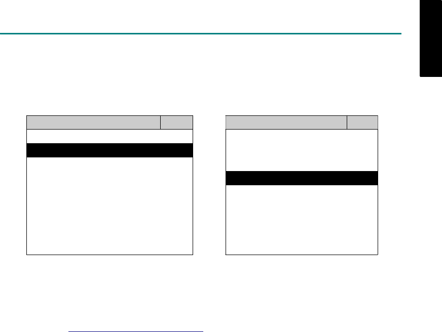
START TO DIAGNOSE
Select MAZDA by pressing the ENTER button. Turn ignition ON or make engine running at idle.
WARNING! Ignition ON without engine running may have a flat battery.
Select the system from the screen. There may be many systems on the vehicle, try to press RIGHT
button to turn the page. If the ECU response is successful, the screen will show all the available
functions.
MAZDA ENGINE
1 ENGINE 1 ID CODES
2 A/T 2 READ FAULT CODE
3 ABS / VST
4 SRS
5 EPS
3 CLEAR FAULT CODE
4 DATA STREAM
6 2-PIN CODE LOOKUP
The figure is for reference only. Autoland Scientech updates the software very often. The screen
shown may not be the same as the newest software delivered. We may simplify the steps of the
procedure.
Autoland Scientech will keep updating the diagnostic software for MAZDA. Please refer to the software
specification.
Visit our website, http://www.autolandscientech.com , and apply for membership. You will get E-paper
every month and find more diagnostic technical information.
iSCAN-II for MAZDA © 2008 Autoland Scientech. Page 3
MAZDA
MAZDA

TROUBLE SHOOTING
iSCAN-
II
never shows anything on LCD screen and there's no back-light?
1. Please check the cable and the connector again.
2. The voltage of the battery should be higher than 10V.
3. Check the power from OBD-II connector. PIN-16 is power, PIN-4 or PIN-5 is ground.
4. Check fuses in BU-EC (25-Pin Base Unit Extension Cable).
iSCAN-
II
never shows anything on LCD screen and the back-light is ON?
1. Check the diagnostic software using iSCAN-II/PSModule3 File Manager from PC. The
software for iSCAN-II may be missing or broken.
2. Adjust the brightness dial for the LCD panel. The brightness may be too dark.
Can't find the system on the screen?
1. Press Right button for more systems. There are too many systems which can't be shown
on the same page.
2. The diagnostic software does not have this system. Please refer to the specification. We
apologize for the inconvenience.
The green or yellow LED flashed on for a while, then showed 'CONNECTION FAILED'
on the LCD screen?
1. Make sure the ignition is ON or make the engine running at idle.
2. Ignition OFF for a while, then Ignition ON and try again.
3. Check the cable and the adapter. Unplug all cables and adapters and plug-in again.
4. Make sure the vehicle equips with the correct system. For example, the manual
transmission will not have A/T transmission ECU.
5. The vehicle will NOT equip with all the systems listed on the software. Some special
systems are only available on the luxury models.
6. The ECU is malfunction or the diagnostic line from the ECU is open or short to the ground or
power.
7. Battery voltage is too low.
Successfully connected to the system but shows 'VERSION UNKNOWN' on the LCD
screen?
Due to the prompt development of the Motor manufactures, the diagnostic software might not
be able to communicate with all ECU versions. Download the newest software from the member
area of Autoland Scientech website and try again. (http://www.autolandscientech.com)
If the same situation occurs, please report the information of ID pages to our local distributors.
We will keep updating the diagnostic software for new ECUs. Please excuse any inconvenience
this may cause.
Successfully connects to the system but shows 'LINK FAILURE' on the title?
Some ECUs are not as stable as our research department expected. Please report the
information of ID pages to our local distributors. Our R/D department will do our best to fix the
problems as soon as possible. Please excuse any inconvenience this may cause.
Document Version 1.00 for iSCAN-II, © 2008 Autoland Scientech
The information contained herein is the exclusive property of Autoland Scientech
®
and shall not be distributed, reproduced, or disclosed
in whole or in part without prior written permission of Autoland Scientech
®
. Autoland Scientech
®
reserve the right to make any change
without notice. The trademarks mentioned belong to the owners.
iSCAN-II for MAZDA © 2008 Autoland Scientech. Page 4
MAZDA
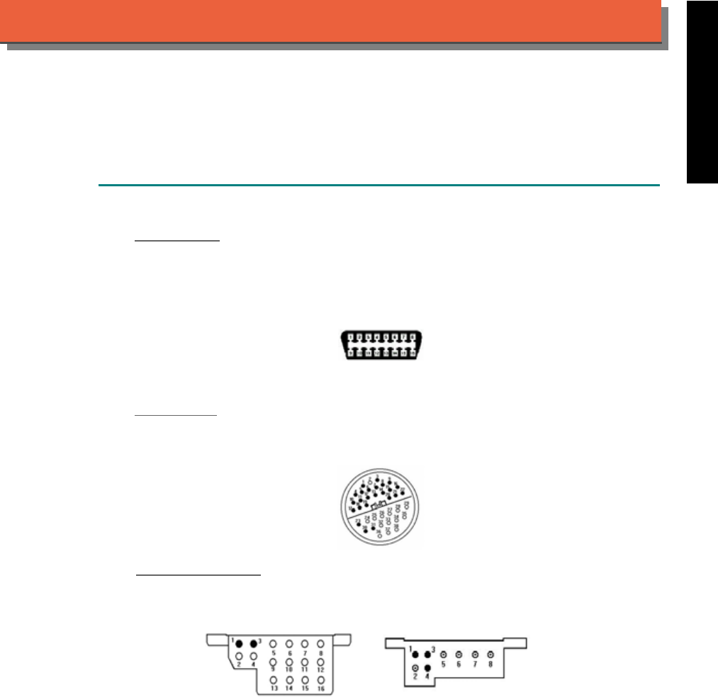
iSCAN-
II
Documentation
MERCEDES BENZ
®
DIAGNOSTIC SYSTEM
GETTING STARTED
1. FIND THE DIAGNOSTIC SOCKET
OBD-
II Soc ket
Most OBD-II diagnostic sockets are located under the steering wheel on driver side and are
covered by a plastic cover. US models from 1995 to 2000 were equipped with both 38-Pin and
OBD-II diagnostic sockets. Only 38-PIN diagnostic socket can work in the diagnostic
communication. OBD-II diagnostic socket is for Generic OBD-II communication purpose only.
OBD-II socket
38-PIN Soc ket
For the old models from 1990 to 2001 equipped with 38-PIN socket. The socket is covered by a
plastic cover, close to the firewall of engine compartment or near the either side of engine
compartment. The diagnostic socket for the van may be found under the driver's seat.
38-PIN socket
16-PIN / 8-PIN Soc ket
For the oldest models, like 107/124/126 and etc., equipped with 16-PIN or 8-PIN socket, the
socket is near the firewall of engine compartment.
16-PIN pole socket 8-PIN pole socket
iSCAN-II for Mercedes Benz © 2008 Autoland Scientech. Page 1
AUT
LAND
®
SCIENTECH
MERCEDES BENZ
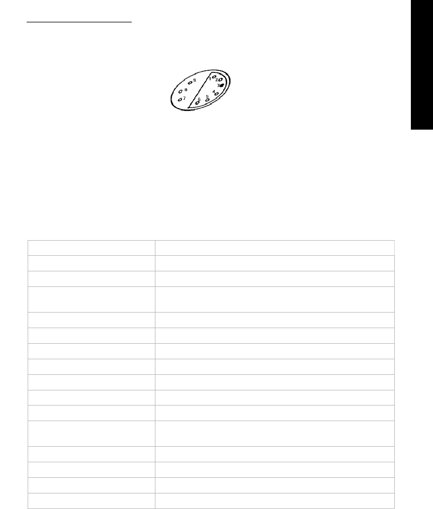
9-Pole Diagnostic Socket
The old models were equipped with 9-Pole diagnostic socket. Using On-Off Ratio Meter or
Multimeter with duty cycle scale to read out the On-Off Ratio fault codes from Pole 3 of the
diagnostic socket.
9-Pole socket
Access trouble codes:
Ensure ignition switched OFF.
Connect Multimeter between data link connector (DLC) Pole 3 and earth.
Switch ignition ON. Check that Multimeter indicates 70%. This indicates that the system has
a fault memory.
Start engine. Allow to idle.
If readout fluctuates: No trouble codes have been recorded.
If readout does not fluctuate: Note trouble codes. Compare with trouble table.
Switch ignition OFF.
Trouble code identification: (Ex. Model W126, 1985-1991, Engine: at idle)
Percentage code: engine idling Fault location
0% Data link connector (DLC) - wiring
0% Weak mixture – with catalyst
10% Closed throttle position (CTP) switch/volume air flow (VAF)
sensor
20% Wide open throttle (WOT) switch
30% Engine coolant temperature (ECT) sensor
40% Volume air flow (VAF) sensor
50% Oxygen sensor (O2S) – with cat
50% No fault – without catalyst
60% Vehicle speed sensor (VSS), during dynamic testing only
70% Engine speed (RPM) sensor
80% Intake air temperature (IAT) sensor (9/89-)/barometric
pressure (BARO) sensor
90% Differential pressure regulator
95% Overrun cut-off active
100% Rich mixture/O2S – with cat
100% Engine control module (ECM) – supply voltage
iSCAN-II for Mercedes Benz © 2008 Autoland Scientech. Page 2
MERCEDES BENZ
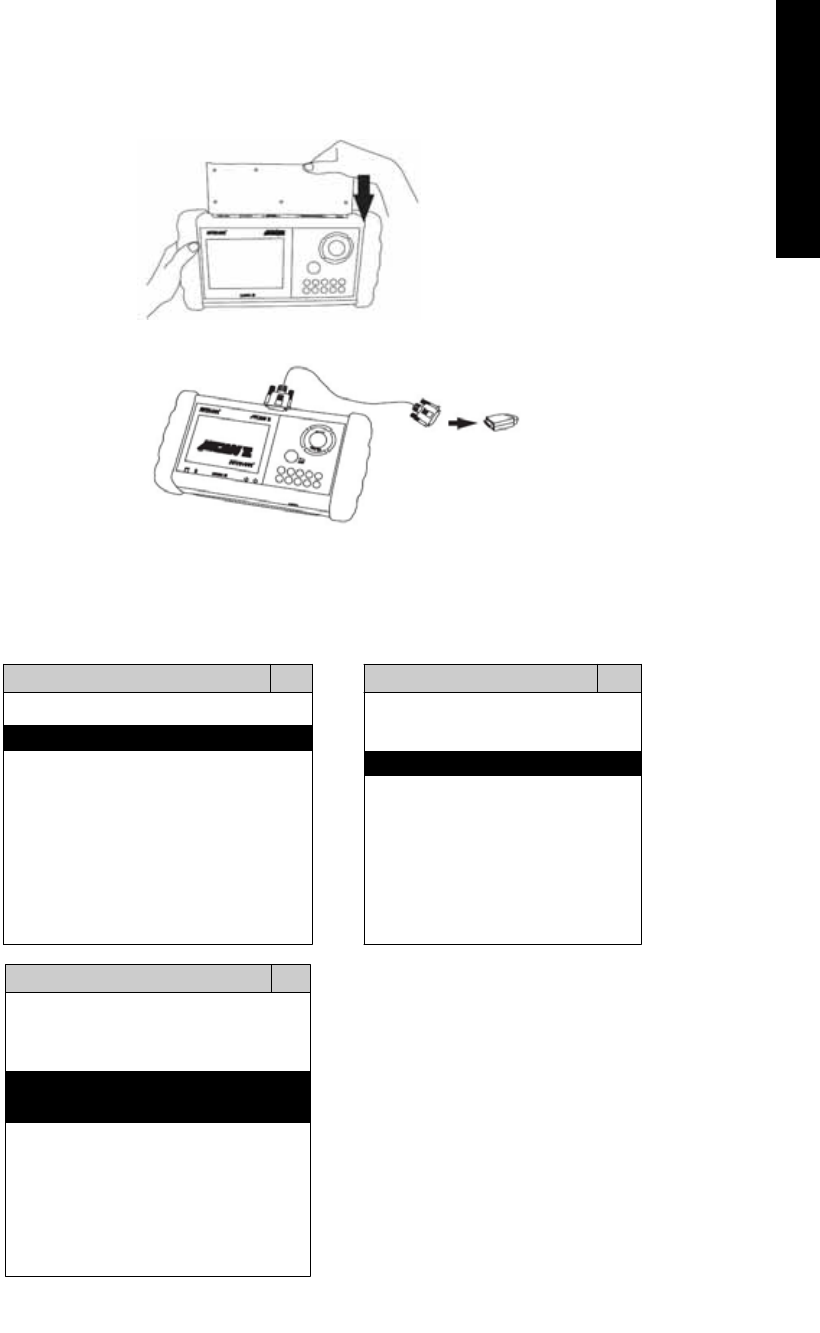
2. SELECT THE INTERFACE MODULE
There are only two interface modules available for MERCEDES BENZ diagnostic system,
OBDII-IM5 and MB38-IM2. Insert the interface module into the base unit firmly. Select the
adapter that corresponds to the socket, ex. OBDII-AC-16P.
3. CONNECT TO THE VEHICLE
Plug the available diagnostic adapter into the diagnostic socket in the vehicles. Select the MB
from the screen of iSCAN-II. Press ENTER to start to diagnostic function. If the model is not
listed on the screen, try to press RIGHT / LEFT buttons to turn the page.
MAIN MENU
Vehicle Diagnostic
1 Vehicle Diagnostic 1 <ASIAN>
2 IMS
2
(Interface Module 2 <EUROPEAN>
Simulation System)
3 Component Test System
10 OBDII Standard Compliant
iSCAN-II(V1.00)
20 SETUP
<EUROPEAN>
1 <BMW GT2>
2 <FRENCH PKG>
3 MB
iSCAN-II (V1.00)
4. FIAT
iSCAN-II (V1.00)
5. JAGUAR
iSCAN-II (V1.00)
6. LANDROVER
iSCAN-II (V1.00)
The figure is for reference only. Autoland Scientech updates the software very often. The
screen shown may not be the same as the newest software delivered.
iSCAN-II for Mercedes Benz © 2008 Autoland Scientech. Page 3
MERCEDES BENZ
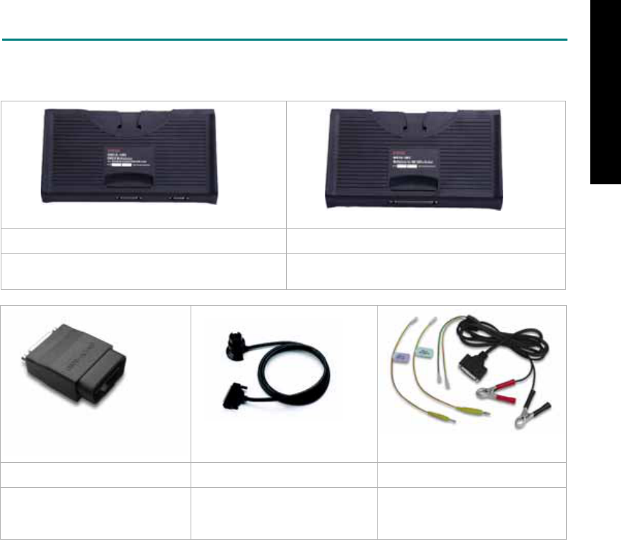
ADAPTERS AND INTERFACE MODULE
There are two interface modules available for the diagnostic system, OBDII-IM5 and MB38-IM2.
Select the interface module corresponds to the socket found in the vehicle.
OBD
II
-IM5 MB38-IM2
OBD-II Full Specification Multiplexer. Mercedes-Benz 38-Pin Electronic Multiplexer for
old models from Year 1990 to 2001.
OBD
II
-AC-16P MB-C-38P D51-C-MBLV
The most common adapter for
the new models. Connect to the
OBDII-IM5 with AC-EC1.
The adapter for the old models. The adapter for the oldest
models. Connect directly to the
iSCAN-II base unit.
There are some adapters available. Refer to the “Diagnostic Cable Connection Quick Manual” for more
detailed connection / wiring information.
iSCAN-II for Mercedes Benz © 2008 Autoland Scientech. Page 4
MERCEDES BENZ
START TO DIAGNOSE
Select MB by pressing the ENTER button. Turn ignition ON or make engine running at idle.
WARNING! Ignition ON without engine running may have a flat battery.
Select the system from the screen. There may be many systems on the vehicle, try to press RIGHT
button to turn the page. If the ECU response is successful, the screen will show all the available
functions.
MB HFM
1 S-Class 1 ID CODES
2 E-Class 2 READ FAULT CODE
3 C-Class
4 ML-Class
5 SL-Class
3 CLEAR FAULT CODE
4 DATA STREAM
5 ACTIVATION
6 A-Class 6 WAVEFORM
7 CODING
8 ADAPTATION
The figure is for reference only. Autoland Scientech updates the software very often. The screen
shown may not be the same as the newest software delivered.
Autoland Scientech will keep updating the diagnostic software for Mercedes-Benz. Please refer to the
software specification.
Visit our website, http://www.autolandscientech.com , and apply for membership. You will get E-paper
every month and find more diagnostic technical information.
iSCAN-II for Mercedes Benz © 2008 Autoland Scientech. Page 5
MERCEDES BENZ

TROUBLE SHOTTING
iSCAN-
II
never shows anything on LCD screen and there's no back-light?
1. Please check the cable and the connector again.
2. The voltage of the battery should be higher than 10V.
3. Check the power from OBD-II connector. PIN-16 is power, PIN-4 or PIN-5 is ground.
4. Check fuses in BU-EC (25-Pin Base Unit Extension Cable).
iSCAN-
II
never shows anything on LCD screen and the back-light is ON?
1. Check the diagnostic software using iSCAN-II/PSModule3 File Manager from PC. The
software for iSCAN-II may be missing or broken.
2. Adjust the brightness dial for the LCD panel. The brightness may be too dark.
Can't find the system on the screen?
1. Press Right button for more systems. There are too many systems which can't be shown
on the same page.
2. The diagnostic software does not have this system. Please refer to the specification. We
apologize for the inconvenience.
The green or yellow LED flashed on for a while, then showed 'CONNECTION FAILED'
on the LCD screen?
1. Make sure the ignition is ON or make the engine running at idle.
2. Ignition OFF for a while, then Ignition ON and try again.
3. Check the cable and the adapter. Unplug all cables and adapters and plug-in again.
4. Make sure the vehicle equips with the correct system. For example, the manual
transmission will not have A/T transmission ECU.
5. The vehicle will NOT equip with all the systems listed on the software. Some special
systems are only available on the luxury models.
6. The ECU is malfunction or the diagnostic line from the ECU is open or short to the ground or
power.
7. Battery voltage is too low.
Successfully connected to the system but shows 'VERSION UNKNOWN' on the LCD
screen?
Due to the prompt development of the Motor manufactures, the diagnostic software might not
be able to communicate with all ECU versions. Download the newest software from the member
area of Autoland Scientech website and try again. (http://www.autolandscientech.com)
If the same situation occurs, please report the information of ID pages to our local distributors.
We will keep updating the diagnostic software for new ECUs. Please excuse any inconvenience
this may cause.
Successfully connects to the system but shows 'LINK FAILURE' on the title?
Some ECUs are not as stable as our research department expected. Please report the
information of ID pages to our local distributors. Our R/D department will do our best to fix the
problems as soon as possible. Please excuse any inconvenience this may cause.
Document Version 1.00 for iSCAN-II, © 2008 Autoland Scientech
The information contained herein is the exclusive property of Autoland Scientech
®
and shall not be distributed, reproduced, or disclosed
in whole or in part without prior written permission of Autoland Scientech
®
. Autoland Scientech
®
reserves the right to make any change
without notice. The trademarks mentioned belong to the owners.
iSCAN-II for Mercedes Benz © 2008 Autoland Scientech. Page 6
MERCEDES BENZ
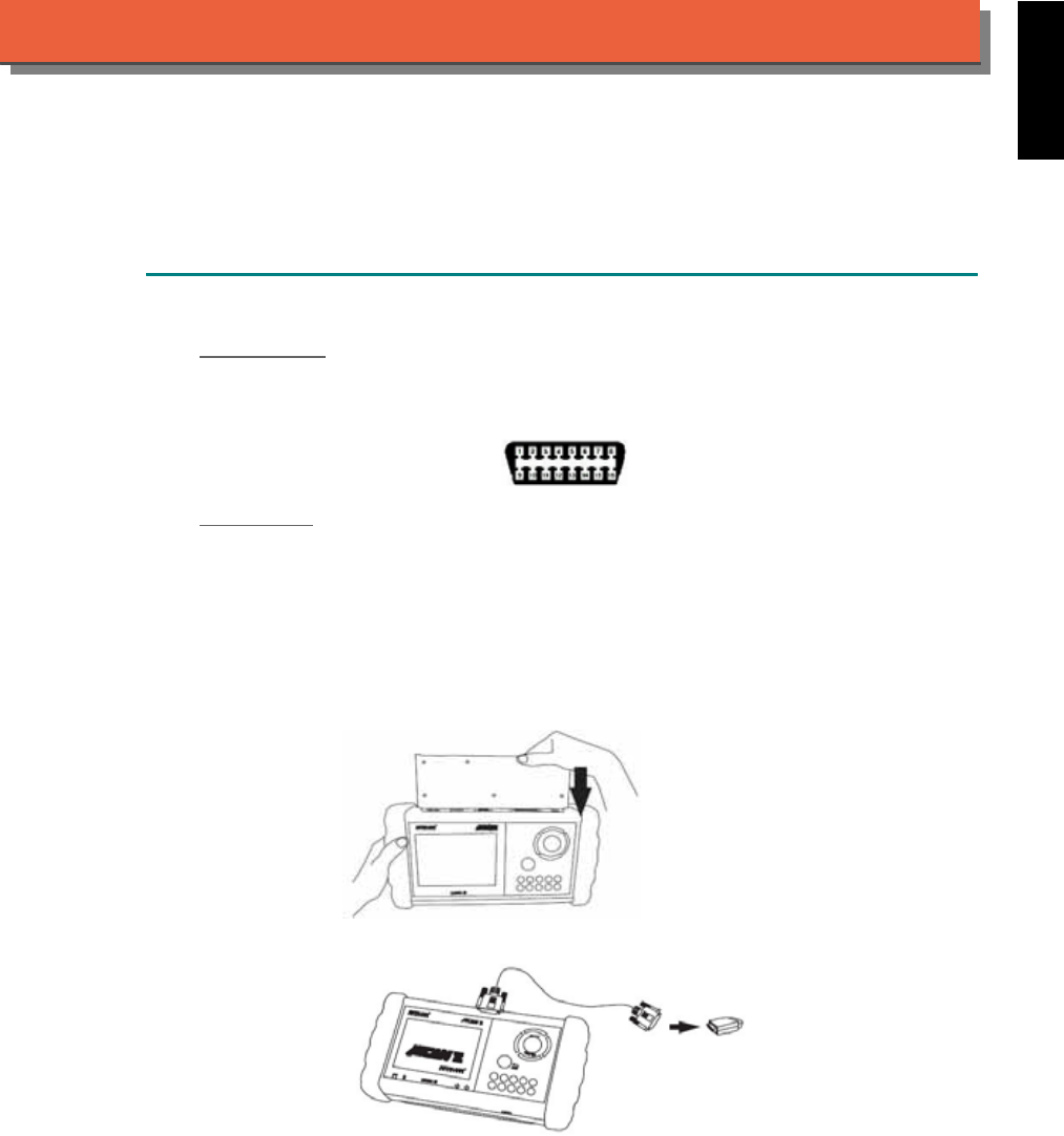
iSCAN-
II
Documentation
MINI
®
DIAGNOSTIC SYSTEM
GETTING STARTED
1. FIND THE DIAGNOSTIC SOCKET
OBD-
II Soc ket
Most OBDII diagnostic socket can be found under the dashboard on driver side and are covered
by a plastic cover.
OBD-II socket
Other Soc ket
iSCAN-II MINI Diagnostic Software does not support the vehicles which are equipped with the
other sockets.
2. SELECT THE INTERFACE MODULE
There is only one interface module available for MINI diagnostic system, OBDII-IM5. Insert the
interface module into the base unit firmly if the socket in the vehicle is OBD-II, and connect the
adapter that corresponds to the socket, OBDII-AC-16P.
iSCAN-II for MINI © 2008 Autoland Scientech. Page 1
AUT
LAND
®
SCIENTECH
MINI
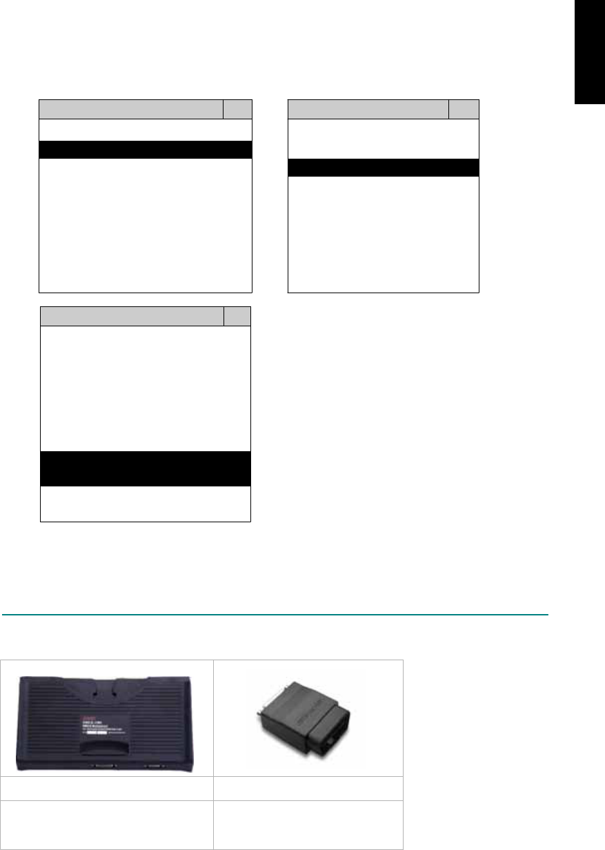
3. CONNECT TO THE VEHICLE
Plug the available diagnostic socket into the diagnostic socket in the vehicles. Select the MINI
from the screen of iSCAN-II. Press ENTER to start to diagnostic function. If the model is not
listed on the screen, try to press RIGHT / LEFT buttons to turn the page.
MAIN MENU
Vehicle Diagnostic
1 Vehicle Diagnostic 1 <ASIAN>
2 IMS
2
(Interface Module 2 <EUROPEAN>
Simulation System)
3 Component Test System
10 OBDII Standard Compliant
iSCAN-II(V1.00)
20 SETUP
<EUROPEAN>
1 <BMW GT2>
2 <FRENCH PKG>
3 MB
iSCAN-II (V1.00)
4. FIAT
iSCAN-II (V1.00)
5. MINI
iSCAN-II (V1.00)
6. LANDROVER
iSCAN-II (V1.00)
The figure is for reference only. Autoland Scientech updates the software very often. The
screen shown may not be the same as the newest software delivered..
ADAPTERS AND INTERFACE MODULE
There is only one interface module available for the diagnostic system, OBDII-IM5.
OBD
II
-IM5 OBD
II
-AC-16P
Insert this interface module for the
models equipped with only OBD-II
socket.
The most common adapter for the
new models. Connect to the
OBDII-IM5 with AC-EC1.
There are some adapters available. Refer to the “Diagnostic Cable Connection Quick Manual” for more
detailed connection / wiring information.
iSCAN-II for MINI © 2008 Autoland Scientech. Page 2
MINI

START TO DIAGNOSE
Select MINI by pressing the ENTER button. Turn ignition ON or make engine running at idle.
WARNING! Ignition ON without engine running may have a flat battery.
Select the system from the screen. There may be many systems on the vehicle, try to press RIGHT
button to turn the page. If the ECU response is successful, the screen will show all the available
functions.
MINI TRANSMISSION
1 ENGINE 1 ID CODES
2 TRANSMISSION 2 READ FAULT CODE
3 ABS
4 SRS
3 CLEAR FAULT CODE
4 DATA STREAM
The figure is for reference only. Autoland Scientech updates the software very often. The screen
shown may not be the same as the newest software delivered. We may simplify the steps of the
procedure.
Autoland Scientech will keep updating the diagnostic software for MINI. Please refer to the software
specification.
Visit our website, http://www.autolandscientech.com , and apply for membership. You will get E-paper
every month and find more diagnostic technical information.
iSCAN-II for MINI © 2008 Autoland Scientech. Page 3
MINI

TROUBLE SHOOTING
iSCAN-
II
never shows anything on LCD screen and there’s no back-light?
1. Please check the cable and the connector again.
2. The voltage of the battery should be higher than 10V.
3. Check the power from OBD-II connector. PIN-16 is power, PIN-4 or PIN-5 is ground.
4. Check fuses in BU-EC (25-Pin Base Unit Extension Cable).
iSCAN-
II
never shows anything on LCD screen and the back-light is ON?
1. Check the diagnostic software using iSCAN-II/PSModule3 File Manager from PC. The
software for iSCAN-II may be missing or broken.
2. Adjust the brightness dial for the LCD panel. The brightness may be too dark.
Can't find the system on the screen?
1. Press Right button for more systems. There are too many systems which can't be shown
on the same page.
2. The diagnostic software does not have this system. Please refer to the specification. We
apologize for the inconvenience.
The green or yellow LED flashed on for a while then showed 'CONNECTION FAILED'
on the LCD screen?
1. Make sure the ignition is ON or make the engine running at idle.
2. Ignition OFF for a while, then Ignition ON and try again.
3. Check the cable and the adapter. Unplug all cables and adapters and plug-in again.
4. Make sure the vehicle equips with the correct system. For example, the manual
transmission will not have A/T transmission ECU.
5. The vehicle will NOT equip with all the systems listed on the software. Some special
systems are only available on the luxury models.
6. The ECU is malfunction or the diagnostic line from the ECU is open or short to the ground or
power.
7. Battery voltage is too low.
Successfully connected to the system but shows 'VERSION UNKNOWN' on the LCD
screen?
Due to the prompt development of the Motor manufactures, the diagnostic software might not
be able to communicate with all ECU versions. Download the newest software from the member
area of Autoland Scientech website and try again. (http://www.autolandscientech.com)
If the same situation occurs, please report the information of ID pages to our local distributors.
We will keep updating the diagnostic software for new ECUs. Please excuse any inconvenience
this may cause.
Successfully connects to the system but shows 'LINK FAILURE' on the title?
Some ECUs are not as stable as our research department expected. Please report the
information of ID pages to our local distributors. Our R/D department will do our best to fix the
problems as soon as possible. Please excuse any inconvenience this may cause.
Document Version 1.00 for iSCAN-II, © 2008 Autoland Scientech
The information contained herein is the exclusive property of Autoland Scientech
®
and shall not be distributed, reproduced, or disclosed
in whole or in part without prior written permission of Autoland Scientech
®
. Autoland Scientech
®
reserves the right to make any change
without notice. The trademarks mentioned belong to the owners.
iSCAN-II for MINI © 2008 Autoland Scientech. Page 4
MINI
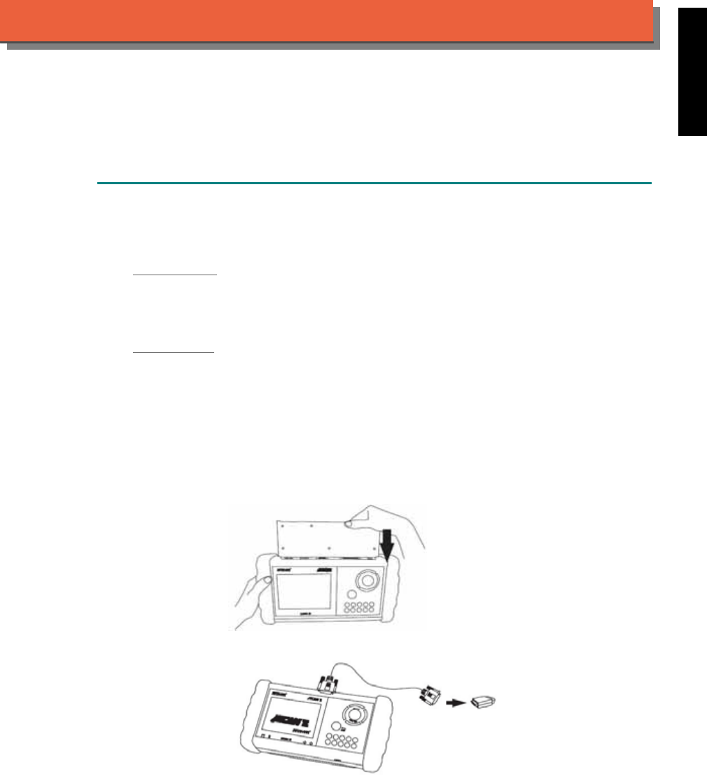
iSCAN-
II
Documentation
MITSUBISHI
®
DIAGNOSTIC SYSTEM
GETTING STARTED
1. FIND THE DIAGNOSTIC SOCKET
There are two kinds of diagnostic sockets for MITSUBISHI diagnostic system. Please note that
prior to the year 2000 most vehicles were equipped with 12-pin socket.
OBD- II Socket
Most OBD-II diagnostic sockets are located under the steering wheel on driver side. For new
models after 2006, the communication protocol of ECUs is CAN. Please use OBDII-IM5 first on
new models, then try ASIAN-IM1 if the communication with some systems are failed.
12-PIN Soc ket
For the old models which equipped with 12-PIN round socket, located in the fuse box under the
steering wheel on the driver side. Some models may be equipped with OBD-II and 12-PIN
connectors together. Try both connectors by using ASIAN-IM1.
2. SELECT THE INTERFACE MODULE
There are two interface modules available for MITSUBISHI diagnostic system, OBDII-IM5 and
ASIAN-IM1. Insert the interface module into the base unit firmly. Select the adapter that
corresponds to the socket, ex. OBDII-AC-16P.
iSCAN-II for MITSUBISHI © 2008 Autoland Scientech. Page 1
AUT
LAND
®
SCIENTECH
MITSUBISHI
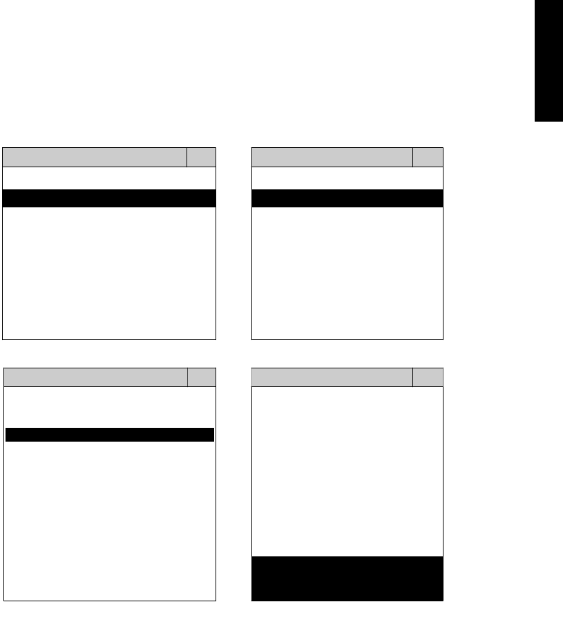
3. CONNECT TO THE VEHICLE
Plug the available diagnostic adapter into the diagnostic socket in the vehicles. Select the
MITSUBISHI from the screen of iSCAN-II. Press ENTER to start the diagnostic function. If the
model is not listed on the screen, try to press RIGHT / LEFT buttons to turn the page. If the
model is equipped with 12-PIN diagnostic socket, plug the cigarette lighter power cable, BU-EC-
1.
MAIN MENU
Vehicle Diagnostic
1 Vehicle Diagnostic 1 <ASIAN>
2 IMS
2
(Interface Module 2 <EUROPEAN>
Simulation System)
3 Component Test System
10 OBDII Standard Compliant
iSCAN-II (V1.00)
20 SETUP
<ASIAN>
<JAPAN>
1 <KOREA>
2 <JAPAN>
1 DAIHATSU NON-CAN
iSCAN-II (V1.00)
3 CHRYSLER
iSCAN-II (V1.00)
4 FORD OEM(OBDII 95~)
2 DAIHATSU CAN
iSCAN-II (V1.00)
3
HONDA
MAZDA OEM(OBDII 01~)
iSCAN-II (V1.00)
5. GM US
iSCAN-II (V1.00)
4 ACURA
iSCAN-II (V1.00)
iSCAN-II (V1.00) 5 MITSUBISHI
iSCAN-II (V1.00)
The figure is for reference only. Autoland Scientech updates the software very often. The
screen shown may not be the same as the newest software delivered.
iSCAN-II for MITSUBISHI © 2008 Autoland Scientech. Page 2
MITSUBISHI
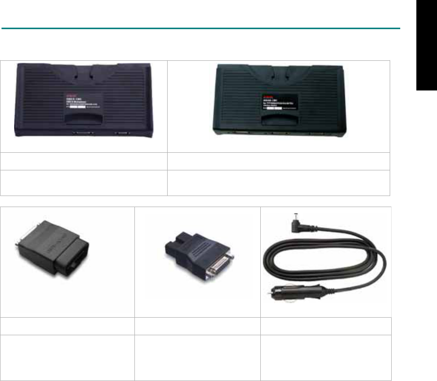
ADAPTERS AND INTERFACE MODULE
There are two interface modules available for the diagnostic system, OBDII-IM5 and ASIAN-IM1.
OBD
II
-IM5 ASIAN-IM1
OBD-II Full Specification Multiplexer ASIAN Interface Module for TOYOTA / NISSAN /
MITSUBISHI / HYUNDAI / KIA
OBD
II
-AC-16P MIT-AC-12P BU-EC-1
The most common adapter for
the new models. Connect to the
OBDII-IM5 or ASIAN-IM1 with
AC-EC1.
The adapter for the old
models. Connect to the
ASIAN-IM1 with AC-EC1.
Ashtray lighter power cable, the
power source for 12-PIN
diagnostic socket models.
There are some adapters available. Refer to the “Diagnostic Cable Connection Quick Manual” for more
detailed connection / wiring information.
iSCAN-II for MITSUBISHI © 2008 Autoland Scientech. Page 3
MITSUBISHI
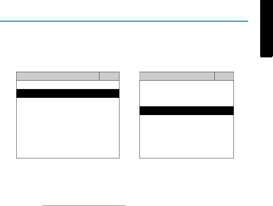
START TO DIAGNOSE
Select MITSUBISHI by pressing the ENTER button. Turn ignition ON or make engine running at idle.
WARNING! Ignition ON without engine running may have a flat battery.
Select the system from the screen. There may be many systems on the vehicle, try to press RIGHT
button to turn the page. If the ECU response is successful, the screen will show all the available
functions.
MITSUBISHI ENGINE
1 ENGINE 1 ID CODES
2 A/T 2 READ FAULT CODE
3 ABS
4 SRS
3 CLEAR FAULT CODE
4 DATA STREAM
5 ACTIVATION
The figure is for reference only. Autoland Scientech updates the software very often. The screen
shown may not be the same as the newest software delivered. We may simplify the steps of the
procedure.
Autoland Scientech will keep updating the diagnostic software for MITSUBISHI. Please refer to the
software specification.
Visit our website, http://www.autolandscientech.com , and apply for membership. You will get E-paper
every month and find more diagnostic technical information.
iSCAN-II for MITSUBISHI © 2008 Autoland Scientech. Page 4
MITSUBISHI
MITSUBISHI

TROUBLE SHOOTING
iSCAN-
II
never shows anything on LCD screen and there's no back-light?
1. Please check the cable and the connector again.
2. The voltage of the battery should be higher than 10V.
3. Check the power from OBD-II connector. PIN-16 is power, PIN-4 or PIN-5 is ground.
4. Check fuses in BU-EC (25-Pin Base Unit Extension Cable).
iSCAN-
II
never shows anything on LCD screen and the back-light is ON?
1. Check the diagnostic software using iSCAN-II/PSModule3 File Manager from PC. The
software for iSCAN-II may be missing or broken.
2. Adjust the brightness dial for the LCD panel. The brightness may be too dark.
Can't find the system on the screen?
1. Press Right button for more systems. There are too many systems which can't be shown
on the same page.
2. The diagnostic software does not have this system. Please refer to the specification. We
apologize for the inconvenience.
The green or yellow LED flashed on for a while, then showed 'CONNECTION FAILED'
on the LCD screen?
1. Make sure the ignition is ON or make the engine running at idle.
2. Ignition OFF for a while, then Ignition ON and try again.
3. Check the cable and the adapter. Unplug all cables and adapters and plug-in again.
4. Make sure the vehicle equips with the correct system. For example, the manual
transmission will not have A/T transmission ECU.
5. The vehicle will NOT equip with all the systems listed on the software. Some special
systems are only available on the luxury models.
6. The ECU is malfunction or the diagnostic line from the ECU is open or short to the ground or
power.
7. Battery voltage is too low.
Successfully connected to the system but shows 'VERSION UNKNOWN' on the LCD
screen?
Due to the prompt development of the Motor manufactures, the diagnostic software might not
be able to communicate with all ECU versions. Download the newest software from the member
area of Autoland Scientech website and try again. (http://www.autolandscientech.com)
If the same situation occurs, please report the information of ID pages to our local distributors.
We will keep updating the diagnostic software for new ECUs. Please excuse any inconvenience
this may cause.
Successfully connects to the system but shows 'LINK FAILURE' on the title?
Some ECUs are not as stable as our research department expected. Please report the
information of ID pages to our local distributors. Our R/D department will do our best to fix the
problems as soon as possible. Please excuse any inconvenience this may cause.
For models manufactured at 2006, which interface module should I insert?
Try OBDII-IM5 first, then ASIAN-IM1. OBDII-IM5 is applicable to CAN-protocol, and ASIAN-
IM1 is to MITSUBISHI specific protocol. To connect with CAN-protocol models, ASIAN-IM1 may
send traditional signals to interrupt the inter-connection of the CAN-bus and cause fault codes.
Please use OBDII-IM5 with iSCAN-II MITSUBISHI diagnostic software to clear the fault code.
Document Version 1.00 for iSCAN-II, © 2008 Autoland Scientech
The information contained herein is the exclusive property of Autoland Scientech
®
and shall not be distributed, reproduced, or disclosed
in whole or in part without prior written permission of Autoland Scientech
®
. Autoland Scientech
®
reserve the right to make any change
without notice. The trademarks mentioned belong to the owners.
iSCAN-II for MITSUBISHI © 2008 Autoland Scientech. Page 5
MITSUBISHI
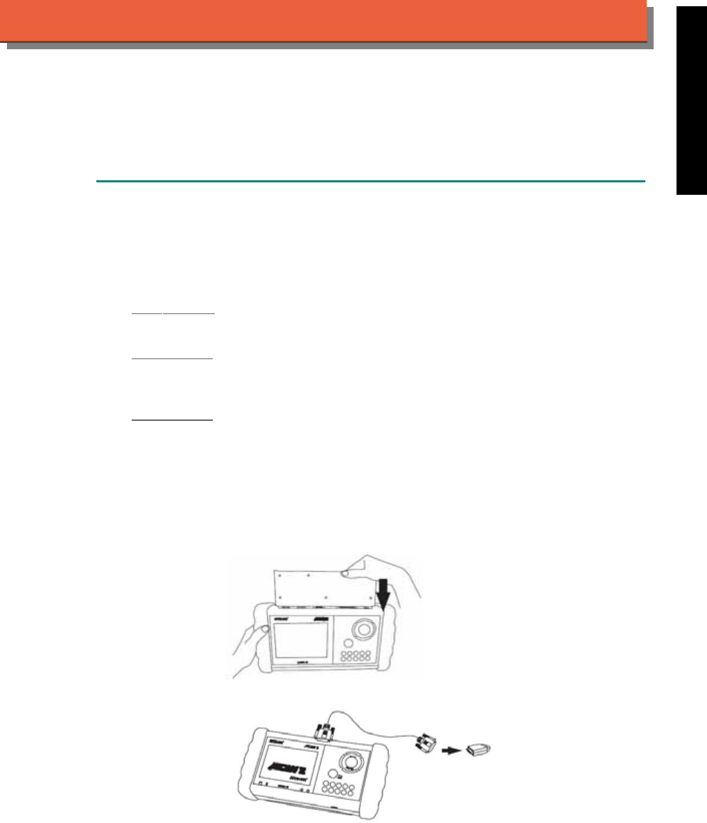
iSCAN-
II
Documentation
OPEL
®
VAUXHALL
®
DIAGNOSTIC SYSTEM
GETTING STARTED
iSCAN-II OPEL Diagnostic Software has many sub-versions for different areas.
1. FIND THE DIAGNOSTIC SOCKET
There are 3 kinds of diagnostic sockets for OPEL / VAUXHALL diagnostic system. Please note
that prior to the year 1998 most vehicles were equipped with 12-pin socket or 10-pin socket.
OBD- II Socket
Most OBD-II diagnostic socket is located under the steering wheel on driver side.
12-PIN Socket
For the old models equipped with 12-PIN socket, the connector of the socket needs the power
source from Ashtray lighter power cable.
10-PIN Socket
The 10-Pin socket is located either in the engine compartment beside the driver side or in the
absorber strut tower on passenger side.
2. SELECT THE INTERFACE MODULE
There is only one interface module available for OPEL diagnostic system, OBDII-IM5. Insert the
interface module into the base unit firmly. Select the adapter that corresponds to the socket, ex.
OBDII-AC-16P.
ISCAN-II for OPEL © 2008 Autoland Scientech. Page 1
AUT
LAND
®
SCIENTECH
OPEL / VAUXHALL
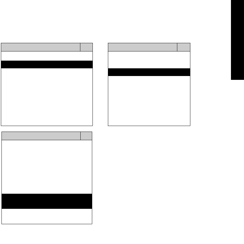
3. CONNECT TO THE VEHICLE
Plug the available diagnostic adapter into the diagnostic socket in the vehicles. Select the OPEL
from the screen of iSCAN-II . Press ENTER to start to diagnostic function. If the model is not
listed on the screen, try to press RIGHT / LEFT buttons to turn the page.
MAIN MENU
Vehicle Diagnostic
1 Vehicle Diagnostic 1 <ASIAN>
2 IMS
2
(Interface Module 2 <EUROPEAN>
Simulation System)
3 Component Test System
10 OBDII Standard Compliant
iSCAN-II(V1.00)
20 SETUP
<EUROPEAN>
1 <BMW GT2>
2 <FRENCH PKG>
3 MB
iSCAN-II (V1.00)
4. FIAT
iSCAN-II (V1.00)
5. OPEL
iSCAN-II (V1.00)
6. OPEL UK
iSCAN-II (V2.00)
The figure is for reference only. Autoland Scientech updates the software very often. The
screen shown may not be the same as the newest software delivered.
ISCAN-II for OPEL © 2008 Autoland Scientech. Page 2
OPEL / VAUXHALL
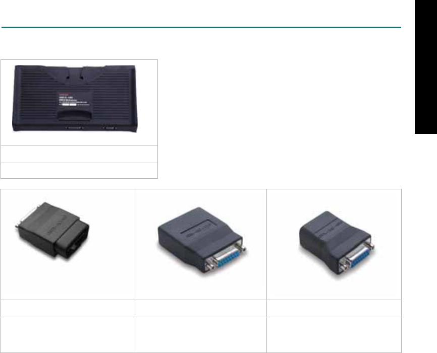
ADAPTERS AND INTERFACE MODULE
There is only one interface module available for the diagnostic system, OBDII-IM5.
OBD
II
-IM5
OBD-II Full Specification Multiplexer
OBD
II
-AC-16P GM-AC-12P OPL-AC-10P
The most common adapter for
the new models. Connect to the
OBDII-IM5 with AC-EC1.
The adapter for the old models. The adapter for the old models.
There are some adapters available. Refer to the “Diagnostic Cable Connection Quick Manual” for more
detailed connection / wiring information.
ISCAN-II for OPEL © 2008 Autoland Scientech. Page 3
OPEL / VAUXHALL
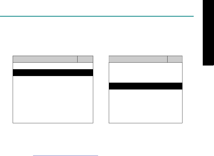
START TO DIAGNOSE
Select OPEL by pressing the ENTER button. Turn ignition ON or make engine running at idle.
WARNING! Ignition ON without engine running may have a flat battery.
Select the system from the screen. There may be many systems on the vehicle, try to press RIGHT
button to turn the page. If the ECU response is successful, the screen will show all the available
functions.
OPEL ENGINE
1 ENGINE 1 ID CODES
2 A/T 2 READ FAULT CODE
3 ABS
4 SRS
3 CLEAR FAULT CODE
4 DATA STREAM
The figure is for reference only. Autoland Scientech updates the software very often. The screen
shown may not be the same as the newest software delivered.
Autoland Scientech will keep updating the diagnostic software for OPEL / VAUXHALL. Please refer to
the software specification.
Visit our website, http://www.autolandscientech.com , and apply for membership. You will get E-paper
every month and find more diagnostic technical information.
ISCAN-II for OPEL © 2008 Autoland Scientech. Page 4
OPEL / VAUXHALL
OPEL / VAUXHALL

TROUBLE SHOOTING
iSCAN-
II
never shows anything on LCD screen and there’s no back-light?
1. Please check the cable and the connector again.
2. The voltage of the battery should be higher than 10V.
3. Check the power from OBD-II connector. PIN-16 is power, PIN-4 or PIN-5 is ground.
4. Check fuses in BU-EC (25-Pin Base Unit Extension Cable).
iSCAN-
II
never shows anything on LCD screen and the back-light is ON?
1. Check the diagnostic software using iSCAN-II/PSModule3 File Manager from PC. The
software for iSCAN-II may be missing or broken.
2. Adjust the brightness dial for the LCD panel. The brightness may be too dark.
Can't find the system on the screen?
1. Press Right button for more systems. There are too many systems which can't be shown
on the same page.
2. The diagnostic software does not have this system. Please refer to the specification. We
apologize for the inconvenience.
The green or yellow LED flashed on for a while then showed 'CONNECTION FAILED'
on the LCD screen?
1. Make sure the ignition is ON or make the engine running at idle.
2. Ignition OFF for a while, then Ignition ON and try again.
3. Check the cable and the adapter. Unplug all cables and adapters and plug-in again.
4. Make sure the vehicle equips with the correct system. For example, the manual
transmission will not have A/T transmission ECU.
5. The vehicle will NOT equip with all the systems listed on the software. Some special
systems are only available on the luxury models.
6. The ECU is malfunction or the diagnostic line from the ECU is open or short to the ground or
power.
7. Battery voltage is too low.
Successfully connected to the system but shows 'VERSION UNKNOWN' on the LCD
screen?
Due to the prompt development of the Motor manufactures, the diagnostic software might not
be able to communicate with all ECU versions. Download the newest software from the member
area of Autoland Scientech website and try again. (http://www.autolandscientech.com)
If the same situation occurs, please report the information of ID pages to our local distributors.
We will keep updating the diagnostic software for new ECUs. Please excuse any inconvenience
this may cause.
Successfully connects to the system but shows 'LINK FAILURE' on the title?
Some ECUs are not as stable as our research department expected. Please report the
information of ID pages to our local distributors. Our R/D department will do our best to fix the
problems as soon as possible. Please excuse any inconvenience this may cause.
Document Version 1.00 for iSCAN-II, © 2008 Autoland Scientech
The information contained herein is the exclusive property of Autoland Scientech
®
and shall not be distributed, reproduced, or disclosed
in whole or in part without prior written permission of Autoland Scientech
®
. Autoland Scientech
®
reserves the right to make any change
without notice. The trademarks mentioned belong to the owners.
ISCAN-II for OPEL © 2008 Autoland Scientech. Page 5
OPEL / VAUXHALL
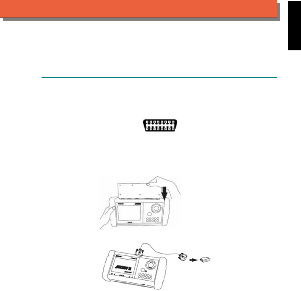
iSCAN-
II
Documentation
PERODUA
®
DIAGNOSTIC SYSTEM
GETTING STARTED
1. FIND THE DIAGNOSTIC SOCKET
OBD-
II
Socket
The OBD-II diagnostic socket is located under the steering wheel on driver side.
OBD-
II
socket
2. SELECT THE INTERFACE MODULE
There is only one interface module available for PERODUA diagnostic system, OBDII-IM5.
Insert the interface module into the base unit firmly. Select the adapter that corresponds to the
socket, ex. OBDII-AC-16P.
iSCAN-II for PERODUA © 2008 Autoland Scientech. Page 1
AUT
LAND
®
SCIENTECH
PERODUA
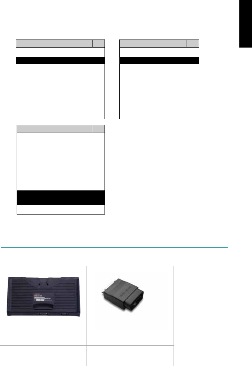
3. CONNECT TO THE VEHICLE
Plug the available diagnostic adapter into the diagnostic socket in the vehicles. Select the
PERODUA from the screen of iSCAN-II . Press ENTER to start the diagnostic function. If the
model is not listed on the screen, try to press RIGHT / LEFT buttons to turn the page.
MAIN MENU
Vehicle Diagnostic
1 Vehicle Diagnostic 1 <ASIAN>
2 IMS
2
(Interface Module 2 <EUROPEAN>
Simulation System)
3 Component Test System
10 OBDII Standard Compliant
iSCAN-II (V1.00)
20 SETUP
<ASIAN>
1 <KOREA>
2 <JAPAN>
3 CHRYSLER
iSCAN-II (V1.00)
4 FORD OEM(OBDII 95~)
MAZDA OEM(OBDII 01~)
iSCAN-II (V1.00)
5. PERODUA
iSCAN-II (V1.00)
The figure is for reference only. Autoland Scientech updates the software very often. The
screen shown may not be the same as the newest software delivered.
ADAPTERS AND INTERFACE MODULE
There is only one interface module available for the diagnostic system, OBDII-IM5.
OBD
II
-IM5 OBD
II
-AC-16P
OBD-II Full Specification Multiplexer The most common adapter for the
new models. Connect to the OBDII-
IM5 with AC-EC1.
There are some adapters available. Refer to the “Diagnostic Cable Connection Quick Manual” for more
detailed connection / wiring information.
iSCAN-II for PERODUA © 2008 Autoland Scientech. Page 2
PERODUA
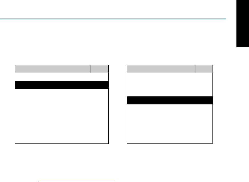
START TO DIAGNOSE
Select PERODUA by pressing the ENTER button. Turn ignition ON or make engine running at idle.
WARNING! Ignition ON without engine running may have a flat battery.
Select the system from the screen. There may be many systems on the vehicle, try to press RIGHT
button to turn the page. If the ECU response is successful, the screen will show all the available
functions.
PERODUA ENGINE
1 ENGINE 1 ID CODES
2 A/T 2 READ FAULT CODE
3 ABS
4 SRS
5 EPS
3 CLEAR FAULT CODE
4 DATA STREAM
The figure is for reference only. Autoland Scientech updates the software very often. The screen
shown may not be the same as the newest software delivered.
Autoland Scientech will keep updating the diagnostic software for PERODUA. Please refer to the
software specification.
Visit our website, http://www.autolandscientech.com , and apply for membership. You will get E-paper
every month and find more diagnostic technical information.
iSCAN-II for PERODUA © 2008 Autoland Scientech. Page 3
PERODUA

TROUBLE SHOOTING
iSCAN-
II
never shows anything on LCD screen and there's no back-light?
1. Please check the cable and the connector again.
2. The voltage of the battery should be higher than 10V.
3. Check the power from OBD-II connector. PIN-16 is power, PIN-4 or PIN-5 is ground.
4. Check fuses in BU-EC (25-Pin Base Unit Extension Cable).
iSCAN-
II
never shows anything on LCD screen and the back-light is ON?
1. Check the diagnostic software using iSCAN-II/PSModule3 File Manager from PC. The
software for iSCAN-II may be missing or broken.
2. Adjust the brightness dial for the LCD panel. The brightness may be too dark.
Can't find the system on the screen?
1. Press Right button for more systems. There are too many systems which can't be shown
on the same page.
2. The diagnostic software does not have this system. Please refer to the specification. We
apologize for the inconvenience.
The green or yellow LED flashed on for a while, then showed 'CONNECTION FAILED'
on the LCD screen?
1. Make sure the ignition is ON or make the engine running at idle.
2. Ignition OFF for a while, then Ignition ON and try again.
3. Check the cable and the adapter. Unplug all cables and adapters and plug-in again.
4. Make sure the vehicle equips with the correct system. For example, the manual
transmission will not have A/T transmission ECU.
5. The vehicle will NOT equip with all the systems listed on the software. Some special
systems are only available on the luxury models.
6. The ECU is malfunction or the diagnostic line from the ECU is open or short to the ground or
power.
7. Battery voltage is too low.
Successfully connected to the system but shows 'VERSION UNKNOWN' on the LCD
screen?
Due to the prompt development of the Motor manufactures, the diagnostic software might not
be able to communicate with all ECU versions. Download the newest software from the member
area of Autoland Scientech website and try again. (http://www.autolandscientech.com)
If the same situation occurs, please report the information of ID pages to our local distributors.
We will keep updating the diagnostic software for new ECUs. Please excuse any inconvenience
this may cause.
Successfully connects to the system but shows 'LINK FAILURE' on the title?
Some ECUs are not as stable as our research department expected. Please report the
information of ID pages to our local distributors. Our R/D department will do our best to fix the
problems as soon as possible. Please excuse any inconvenience this may cause.
Document Version 1.00 for iSCAN-II, © 2008 Autoland Scientech
The information contained herein is the exclusive property of Autoland Scientech
®
and shall not be distributed, reproduced, or disclosed
in whole or in part without prior written permission of Autoland Scientech
®
. Autoland Scientech
®
reserve the right to make any change
without notice. The trademarks mentioned belong to the owners.
iSCAN-II for PERODUA © 2008 Autoland Scientech. Page 4
PERODUA

iSCAN-
II
Documentation
PEUGEOT
®
DIAGNOSTIC SYSTEM
GETTING STARTED
1. FIND THE DIAGNOSTIC SOCKET
OBD-
II Soc ket
Most OBD-II diagnostic socket can be found under the dashboard on driver side and are
covered by a plastic cover. Some of them can be found behind the Ashtray box or the relay box.
OBD-II socket
2. SELECT THE INTERFACE MODULE
There is only one interface module available for PEUGEOT diagnostic system, OBDII-IM5.
Insert the interface module into the base unit firmly if the socket in the vehicle is OBD-II, and
connect the adapter that corresponds to the socket, OBDII-AC-16P.
iSCAN-II for PEUGEOT © 2008 Autoland Scientech. Page 1
AUT
LAND
®
SCIENTECH
PEUGEOT
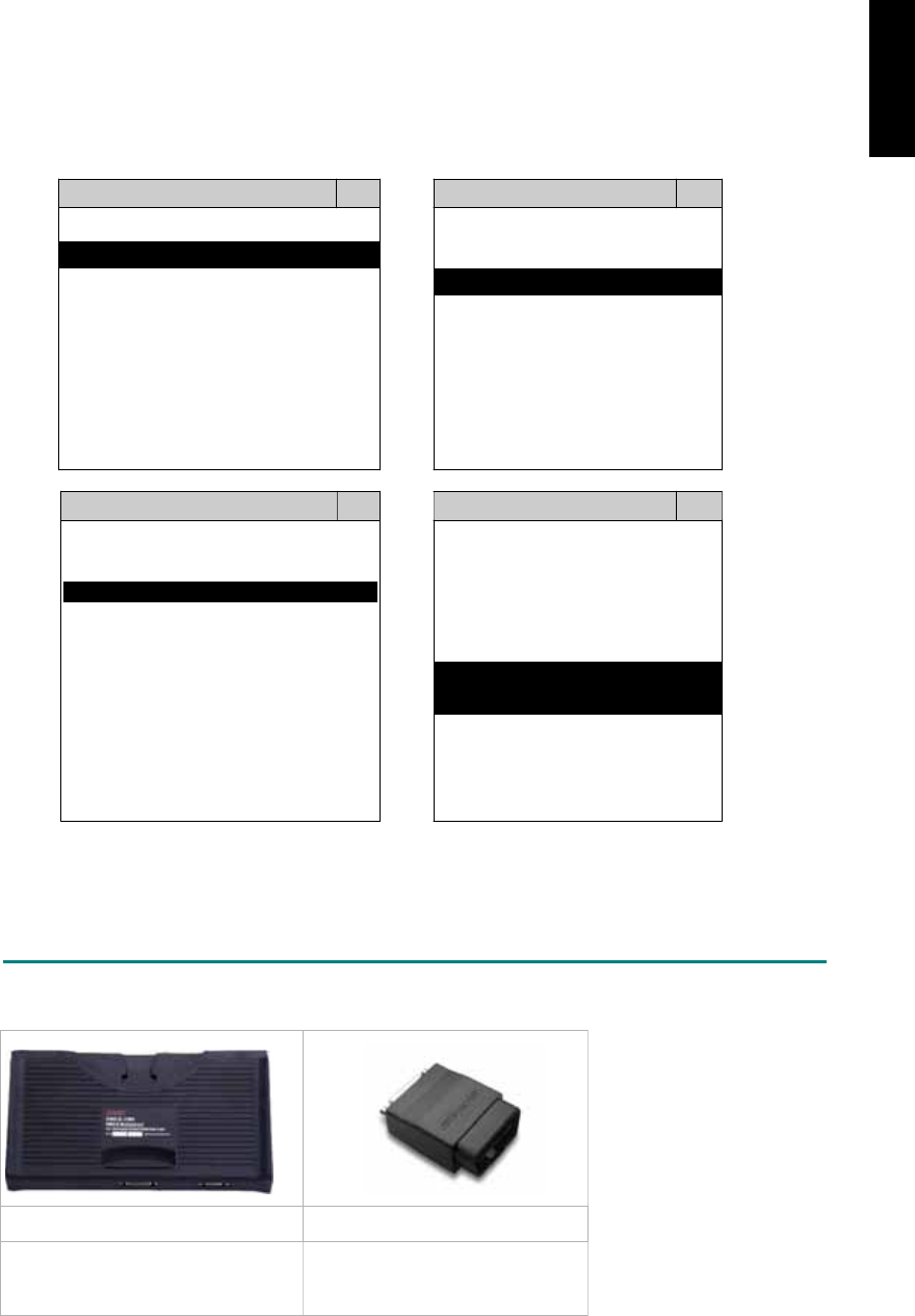
3. CONNECT TO THE VEHICLE
Plug the available diagnostic adapter into the diagnostic socket in the vehicles. Select the
PEUGEOT from the screen of iSCAN-II. Press ENTER to start to diagnostic function. If the
model is not listed on the screen, try to press RIGHT / LEFT buttons to turn the page.
MAIN MENU
Vehicle Diagnostic
1 Vehicle Diagnostic 1 <ASIAN>
2 IMS
2
(Interface Module 2 <EUROPEAN>
Simulation System)
3 Component Test System
10 OBDII Standard Compliant
iSCAN-II(V1.00)
20 SETUP
<EUROPEAN>
FRENCH PKG
1 <BMW GT2>
2 <FRENCH PKG>
1 RENAULT
iSCAN-II (V1.00)
3 MB
iSCAN-II (V1.00)
4. FIAT
2 CITROEN
iSCAN-II (V1.00)
3 PEUGEOT
iSCAN-II (V1.00)
5. JAGUAR
iSCAN-II (V1.00)
iSCAN-II (V1.00)
6. LANDROVER
iSCAN-II (V1.00)
The figure is for reference only. Autoland Scientech updates the software very often. The
screen shown may not be the same as the newest software delivered.
ADAPTERS AND INTERFACE MODULE
There is only one interface module available for the diagnostic system, OBDII-IM5.
OBD
II
-IM5 OBD
II
-AC-16P
Insert this interface module for the
models equipped with only OBD-II
socket.
The most common adapter for
the new models. Connect to the
OBDII-IM5 with AC-EC1.
There are some adapters available. Refer to the “Diagnostic Cable Connection Quick Manual” for more
detailed connection / wiring information.
iSCAN-II for PEUGEOT © 2008 Autoland Scientech. Page 2
PEUGEOT

START TO DIAGNOSE
Select PEUGEOT by pressing the ENTER button. Turn ignition ON or make engine running at idle.
WARNING! Ignition ON without engine running may have a flat battery.
Select the system from the screen. There may be many systems on the vehicle, try to press RIGHT
button to turn the page. If the ECU response is successful, the screen will show all the available
functions.
PEUGEOT ENGINE
1 106 1 ID CODES
2 206 2 READ FAULT CODE
3 207
4 306
5 307
3 CLEAR FAULT CODE
4 DATA STREAM
6 406
7 407
8 607
The figure is for reference only. Autoland Scientech updates the software very often. The screen
shown may not be the same as the newest software delivered. We may simplify the steps of the
procedure.
Autoland Scientech will keep updating the diagnostic software for PEUGEOT. Please refer to the
software specification.
Visit our website, http://www.autolandscientech.com , and apply for membership. You will get E-paper
every month and find more diagnostic technical information.
iSCAN-II for PEUGEOT © 2008 Autoland Scientech. Page 3
PEUGEOT

TROUBLE SHOOTING
iSCAN-
II
never shows anything on LCD screen and there’s no back-light?
1. Please check the cable and the connector again.
2. The voltage of the battery should be higher than 10V.
3. Check the power from OBD-II connector. PIN-16 is power, PIN-4 or PIN-5 is ground.
4. Check fuses in BU-EC (25-Pin Base Unit Extension Cable).
iSCAN-
II
never shows anything on LCD screen and the back-light is ON?
1. Check the diagnostic software using iSCAN-II/PSModule3 File Manager from PC. The
software for iSCAN-II may be missing or broken.
2. Adjust the brightness dial for the LCD panel. The brightness may be too dark.
Can't find the system on the screen?
1. Press Right button for more systems. There are too many systems which can't be shown
on the same page.
2. The diagnostic software does not have this system. Please refer to the specification. We
apologize for the inconvenience.
The green or yellow LED flashed on for a while then showed 'CONNECTION FAILED'
on the LCD screen?
1. Make sure the ignition is ON or make the engine running at idle.
2. Ignition OFF for a while, then Ignition ON and try again.
3. Check the cable and the adapter. Unplug all cables and adapters and plug-in again.
4. Make sure the vehicle equips with the correct system. For example, the manual
transmission will not have A/T transmission ECU.
5. The vehicle will NOT equip with all the systems listed on the software. Some special
systems are only available on the luxury models.
6. The ECU is malfunction or the diagnostic line from the ECU is open or short to the ground or
power.
7. Battery voltage is too low.
Successfully connected to the system but shows 'VERSION UNKNOWN' on the LCD
screen?
Due to the prompt development of the Motor manufactures, the diagnostic software might not
be able to communicate with all ECU versions. Download the newest software from the member
area of Autoland Scientech website and try again. (http://www.autolandscientech.com)
If the same situation occurs, please report the information of ID pages to our local distributors.
We will keep updating the diagnostic software for new ECUs. Please excuse any inconvenience
this may cause.
Successfully connects to the system but shows 'LINK FAILURE' on the title?
Some ECUs are not as stable as our research department expected. Please report the
information of ID pages to our local distributors. Our R/D department will do our best to fix the
problems as soon as possible. Please excuse any inconvenience this may cause.
Document Version 1.00 for iSCAN-II, © 2008 Autoland Scientech
The information contained herein is the exclusive property of Autoland Scientech
®
and shall not be distributed, reproduced, or disclosed
in whole or in part without prior written permission of Autoland Scientech
®
. Autoland Scientech
®
reserves the right to make any change
without notice. The trademarks mentioned belong to the owners.
iSCAN-II for PEUGEOT © 2008 Autoland Scientech. Page 4
PEUGEOT
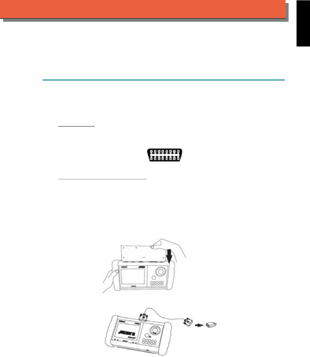
iSCAN-
II
Documentation
PORSCHE
®
DIAGNOSTIC SYSTEM
GETTING STARTED
1. FIND THE DIAGNOSTIC SOCKET
There are two kinds of diagnostic adapters for PORSCHE diagnostic system. Please note that
prior to the year 2000 most vehicles were equipped with the PORSCHE specified socket under
the dash board.
OBD- II Soc ket
For the newer models, ex. Cayenne, 996, Cayman...etc, the diagnostic socket can be found
under the dashboard on driver side and covered by a plastic cover. It is very close to side kicker
and near the door.
OBD-II socket
19-PIN PORSCHE Specified Soc ket
19-Pin diagnostic socket can be found under the dashboard on driver side or under the glove
compartment on passenger's.
2. SELECT THE INTERFACE MODULE
There is only one interface module available for PORSCHE diagnostic system, OBDII-IM5.
Insert the interface module into the base unit firmly if the socket in the vehicle is OBD-II, and
connect the adapter that corresponds to the socket, OBDII-AC-16P.
iSCAN-II for PORSCHE © 2008 Autoland Scientech. Page 1
AUT
LAND
®
SCIENTECH
PORSCHE
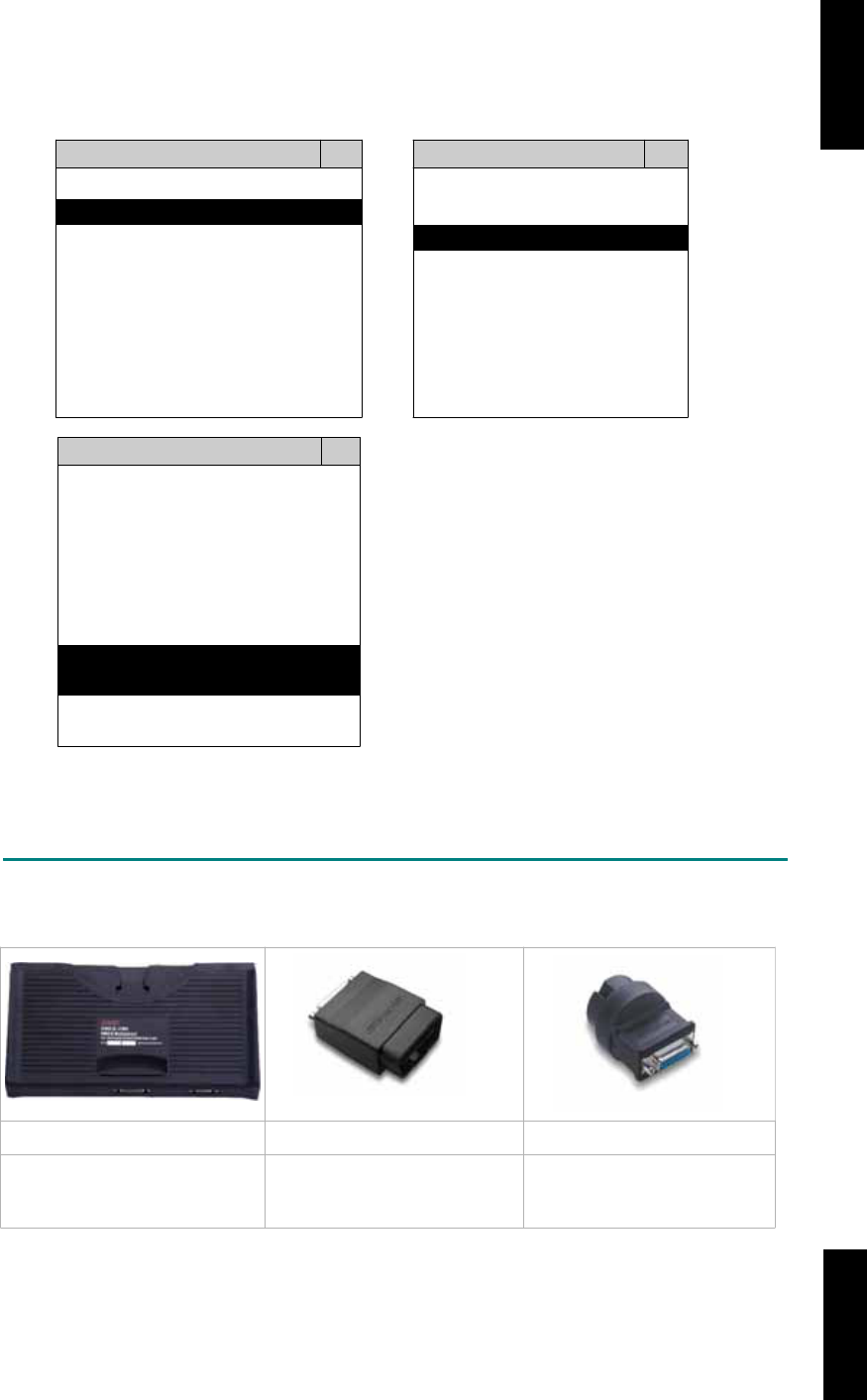
3. CONNECT TO THE VEHICLE
Plug the available diagnostic adapter into the diagnostic socket in the vehicle. Select the
PORSCHE from the screen of iSCAN-II. Press ENTER to start to diagnostic function. If the
model is not listed on the screen, try to press RIGHT / LEFT buttons to turn the page.
MAIN MENU
Vehicle Diagnostic
1 Vehicle Diagnostic 1 <ASIAN>
2 IMS
2
(Interface Module 2 <EUROPEAN>
Simulation System)
3 Component Test System
10 OBDII Standard Compliant
iSCAN-II(V1.00)
20 SETUP
<EUROPEAN>
1 <BMW GT2>
2 <FRENCH PKG>
3 MB
iSCAN-II (V1.00)
4. FIAT
iSCAN-II (V1.00)
5. PROSCHE
iSCAN-II (V1.00)
6. LANDROVER
iSCAN-II (V1.00)
The figure is for reference only. Autoland Scientech updates the software very often. The
screen shown may not be the same as the newest software delivered.
ADAPTERS AND INTERFACE MODULE
There is only one interface module available for the diagnostic system, OBDII-IM5.
OBD
II
-IM5 OBD
II
-AC-16P PCSH-AC-19P
Insert this interface module for
the models equipped with only
OBD-II socket.
The most common adapter for
the new models. Connect to the
OBDII-IM5 with AC-EC1.
The adapter for the old
models. Connect directly to
iSCAN-II using BU-EC.
There are some adapters available. Refer to the “Diagnostic Cable Connection Quick Manual” for more
detailed connection / wiring information.
iSCAN-II for PORSCHE © 2008 Autoland Scientech. Page 2
PORSCHE PORSCHE
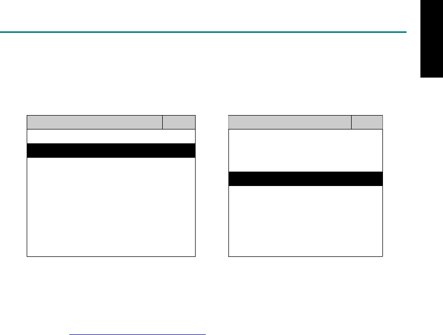
START TO DIAGNOSE
Select PORSCHE by pressing the ENTER button. Turn ignition ON or make engine running at idle.
WARNING! Ignition ON without engine running may have a flat battery.
Select the system from the screen. There may be many systems on the vehicle, try to press RIGHT
button to turn the page. If the ECU response is successful, the screen will show all the available
functions.
PORSCHE DME 7.2
1 Ca
y
enne 1 ID CODES
2 Ca
y
man 2 READ FAULT CODE
3 997
4 987
5 996
3 CLEAR FAULT CODE
4 DATA STREAM
5 ACTIVATION
6 986 6 ADAPTATION
7 968
8 944
The figure is for reference only. Autoland Scientech updates the software very often. The screen
shown may not be the same as the newest software delivered. We may simplify the steps of the
procedure.
Autoland Scientech will keep updating the diagnostic software for PORSCHE. Please refer to the
software specification.
Visit our website, http://www.autolandscientech.com , and apply for membership. You will get E-paper
every month and find more diagnostic technical information.
iSCAN-II for PORSCHE © 2008 Autoland Scientech. Page 3
PORSCHE

TROUBLE SHOOTING
iSCAN-
II
never shows anything on LCD screen and there’s no back-light?
1. Please check the cable and the connector again.
2. The voltage of the battery should be higher than 10V.
3. Check the power from OBD-II connector. PIN-16 is power, PIN-4 or PIN-5 is ground.
4. Check fuses in BU-EC (25-Pin Base Unit Extension Cable).
iSCAN-
II
never shows anything in LCD screen and the back-light is ON?
1. Check the diagnostic software using iSCAN-II/PSModule3 File Manager from PC. The
software for iSCAN-II may be missing or broken.
2. Adjust the brightness dial for the LCD panel. The brightness may be too dark.
Can't find the system on the screen?
1. Press Right button for more systems. There are too many systems which can't be shown
on the same page.
2. The diagnostic software does not have this system. Please refer to the specification. We
apologize for the inconvenience.
The green or yellow LED flashed on for a while, then showed 'CONNECTION FAILED'
on the LCD screen?
1. Make sure the ignition is ON or make the engine running at idle.
2. Ignition OFF for a while, then Ignition ON and try again.
3. Check the cable and the adapter. Unplug all cables and adapters and plug-in again.
4. Make sure the vehicle equips with the correct system. For example, the manual
transmission will not have A/T transmission ECU.
5. The vehicle will NOT equip with all the systems listed on the software. Some special
systems are only available on the luxury models.
6. The ECU is malfunction or the diagnostic line from the ECU is open or short to the ground or
power.
7. Battery voltage is too low.
Successfully connected to the system but shows 'VERSION UNKNOWN' on the LCD
screen?
Due to the prompt development of the Motor manufactures, the diagnostic software might not
be able to communicate with all ECU versions. Download the newest software from the member
area of Autoland Scientech website and try again. (http://www.autolandscientech.com)
If the same situation occurs, please report the information of ID pages to our local distributors.
We will keep updating the diagnostic software for new ECUs. Please excuse any inconvenience
this may cause.
Successfully connects to the system but shows 'LINK FAILURE' on the title?
Some ECUs are not as stable as our research department expected. Please report the
information of ID pages to our local distributors. Our R/D department will do our best to fix the
problems as soon as possible. Please excuse any inconvenience this may cause.
Document Version 1.00 for iSCAN-II, © 2008 Autoland Scientech
The information contained herein is the exclusive property of Autoland Scientech
®
and shall not be distributed, reproduced, or disclosed
in whole or in part without prior written permission of Autoland Scientech
®
. Autoland Scientech
®
reserves the right to make any change
without notice. The trademarks mentioned belong to the owners.
iSCAN-II for PORSCHE © 2008 Autoland Scientech. Page 4
PORSCHE
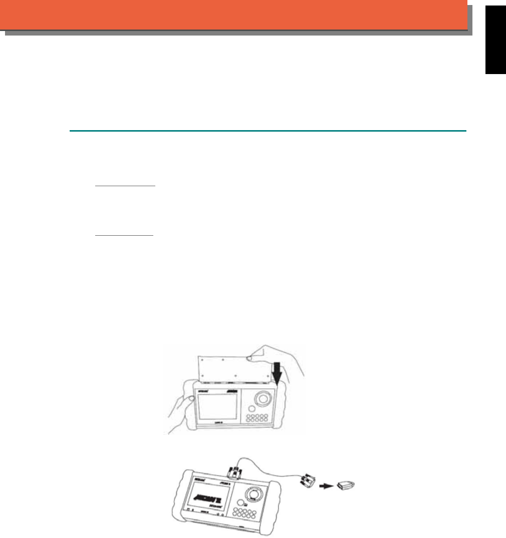
iSCAN-
II
Documentation
PROTON
®
DIAGNOSTIC SYSTEM
GETTING STARTED
1. FIND THE DIAGNOSTIC SOCKET
There are two kinds of diagnostic sockets for PROTON diagnostic system.
OBD-
II Socket
Most OBD-II diagnostic sockets are located under the steering wheel on driver side. Please use
ASIAN-IM1.
12-PIN Soc ket
For the old models equipped with 12-PIN round socket, located in the fuse box under the
steering wheel on driver side. Some models may be equipped with OBD-II and 12-PIN
connectors together. Try both connectors by using ASIAN-IM1.
2. SELECT THE INTERFACE MODULE
There is only one interface module available for PROTON diagnostic system, ASIAN-IM1. Insert
the interface module into the base unit firmly. Select the adapter that corresponds to the socket,
ex. OBDII-AC-16P.
iSCAN-II for PROTON © 2008 Autoland Scientech. Page 1
AUT
LAND
®
SCIENTECH
PROTON
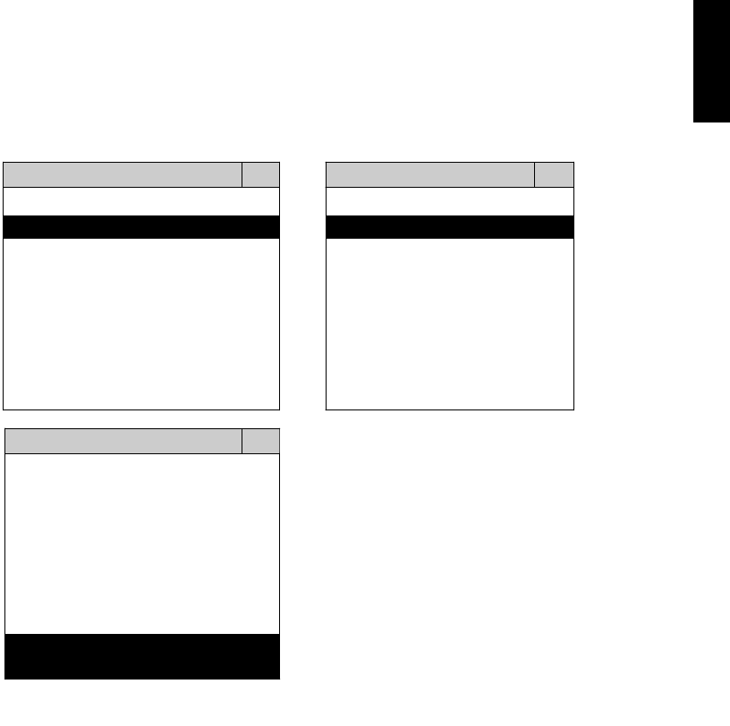
3. CONNECT TO THE VEHICLE
Plug the available diagnostic adapter into the diagnostic socket in the vehicles. Select the
PROTON from the screen of iSCAN-II. Press ENTER to start the diagnostic function. If the
model is not listed on the screen, try to press RIGHT / LEFT buttons to turn the page. If the
model is equipped with 12-PIN diagnostic socket, plug the cigarette lighter power cable, BU-EC-
1.
MAIN MENU
Vehicle Diagnostic
1 Vehicle Diagnostic 1 <ASIAN>
2 IMS
2
(Interface Module 2 <EUROPEAN>
Simulation System)
3 Component Test System
10 OBDII Standard Compliant
iSCAN-II (V1.00)
20 SETUP
<ASIAN>
1 <KOREA>
2 <JAPAN>
3 CHRYSLER
iSCAN-II (V1.00)
4 FORD OEM(OBDII 95~)
MAZDA OEM(OBDII 01~)
iSCAN-II (V1.00)
5. PROTON
iSCAN-II (V1.00)
The figure is for reference only. Autoland Scientech updates the software very often. The
screen shown may not be the same as the newest software delivered.
iSCAN-II for PROTON © 2008 Autoland Scientech. Page 2
PROTON
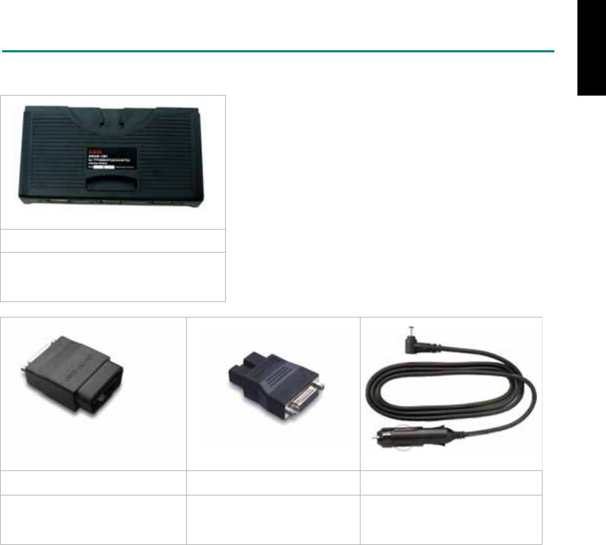
ADAPTERS AND INTERFACE MODULE
There is only one interface module available for the diagnostic system, ASIAN-IM1.
ASIAN-IM1
ASIAN Interface Module for TOYOTA /
NISSAN / MITSUBISHI / HYUNDAI /
KIA
OBD
II
-AC-16P MIT-AC-12P BU-EC-1
The most common adapter for
the new models. Connect to the
ASIAN-IM1 with AC-EC1.
The adapter for the old
models. Connect to the
ASIAN-IM1 with AC-EC1.
Ashtray lighter power cable, the
power source for 12-PIN
diagnostic socket models.
There are some adapters available. Refer to the “Diagnostic Cable Connection Quick Manual” for more
detailed connection / wiring information.
iSCAN-II for PROTON © 2008 Autoland Scientech. Page 3
PROTON
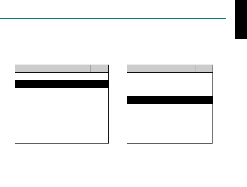
START TO DIAGNOSE
Select PROTON by pressing the ENTER button. Turn ignition ON or make engine running at idle.
WARNING! Ignition ON without engine running may have a flat battery.
Select the system from the screen. There may be many systems on the vehicle, try to press RIGHT
button to turn the page. If the ECU response is successful, the screen will show all the available
functions.
PROTON ENGINE
1 ENGINE 1 ID CODES
2 A/T 2 READ FAULT CODE
3 ABS
4 SRS
3 CLEAR FAULT CODE
4 DATA STREAM
5 ACTIVATION
The figure is for reference only. Autoland Scientech updates the software very often. The screen
shown may not be the same as the newest software delivered. We may simplify the steps of the
procedure.
Autoland Scientech will keep updating the diagnostic software for PROTON. Please refer to the
software specification.
Visit our website, http://www.autolandscientech.com , and apply for membership. You will get E-paper
every month and find more diagnostic technical information.
iSCAN-II for PROTON © 2008 Autoland Scientech. Page 4
PROTON

TROUBLE SHOOTING
iSCAN-
II
never shows anything on LCD screen and there's no back-light?
1. Please check the cable and the connector again.
2. The voltage of the battery should be higher than 10V.
3. Check the power from OBD-II connector. PIN-16 is power, PIN-4 or PIN-5 is ground.
4. Check fuses in BU-EC (25-Pin Base Unit Extension Cable).
iSCAN-
II
never shows anything on LCD screen and the back-light is ON?
1. Check the diagnostic software using iSCAN-II/PSModule3 File Manager from PC. The
software for iSCAN-II may be missing or broken.
2. Adjust the brightness dial for the LCD panel. The brightness may be too dark.
Can't find the system on the screen?
1. Press Right button for more systems. There are too many systems which can't be shown
on the same page.
2. The diagnostic software does not have this system. Please refer to the specification. We
apologize for the inconvenience.
The green or yellow LED flashed on for a while, then showed 'CONNECTION FAILED'
on the LCD screen?
1. Make sure the ignition is ON or make the engine running at idle.
2. Ignition OFF for a while, then Ignition ON and try again.
3. Check the cable and the adapter. Unplug all cables and adapters and plug-in again.
4. Make sure the vehicle equips with the correct system. For example, the manual
transmission will not have A/T transmission ECU.
5. The vehicle will NOT equip with all the systems listed on the software. Some special
systems are only available on the luxury models.
6. The ECU is malfunction or the diagnostic line from the ECU is open or short to the ground or
power.
7. Battery voltage is too low.
Successfully connected to the system but shows 'VERSION UNKNOWN' on the LCD
screen?
Due to the prompt development of the Motor manufactures, the diagnostic software might not
be able to communicate with all ECU versions. Download the newest software from the member
area of Autoland Scientech website and try again. (http://www.autolandscientech.com)
If the same situation occurs, please report the information of ID pages to our local distributors.
We will keep updating the diagnostic software for new ECUs. Please excuse any inconvenience
this may cause.
Successfully connects to the system but shows 'LINK FAILURE' on the title?
Some ECUs are not as stable as our research department expected. Please report the
information of ID pages to our local distributors. Our R/D department will do our best to fix the
problems as soon as possible. Please excuse any inconvenience this may cause.
Document Version 1.00 for iSCAN-II, © 2008 Autoland Scientech
The information contained herein is the exclusive property of Autoland Scientech
®
and shall not be distributed, reproduced, or disclosed
in whole or in part without prior written permission of Autoland Scientech
®
. Autoland Scientech
®
reserve the right to make any change
without notice. The trademarks mentioned belong to the owners.
iSCAN-II for PROTON © 2008 Autoland Scientech. Page 5
PROTON

iSCAN-
II
Documentation
RENAULT
®
DIAGNOSTIC SYSTEM
GETTING STARTED
1. FIND THE DIAGNOSTIC SOCKET
OBD-
II Soc ket
Most OBD-II diagnostic sockets can be found under the dashboard on driver side and are
covered by a plastic cover. Some of them can be found behind the Ashtray or the relay box.
OBD-II socket
2. SELECT THE INTERFACE MODULE
There is only one interface module available for RENAULT diagnostic system, OBDII-IM5.
Insert the interface module into the base unit firmly if the socket in the vehicle is OBD-II, and
connect the adapter that corresponds to the socket, OBDII-AC-16P.
iSCAN-II for RENAULT © 2008 Autoland Scientech. Page 1
AUT
LAND
®
SCIENTECH
RENAULT
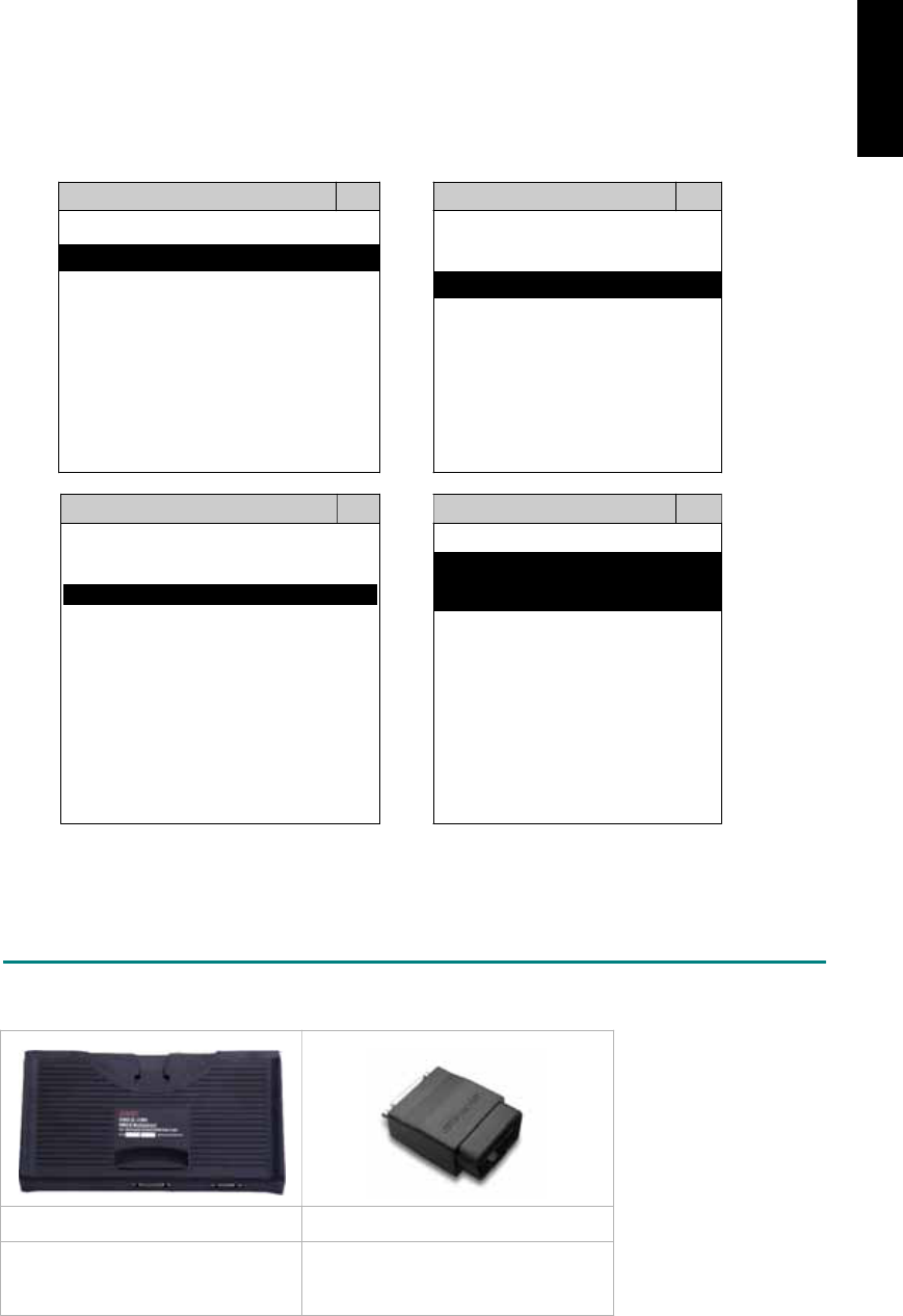
3. CONNECT TO THE VEHICLE
Plug the available diagnostic adapter into the diagnostic socket in the vehicle. Select the
RENAULT from the screen of iSCAN-II . Press ENTER to start to diagnostic function. If the
model is not listed on the screen, try to press RIGHT / LEFT buttons to turn the page.
MAIN MENU
Vehicle Diagnostic
1 Vehicle Diagnostic 1 <ASIAN>
2 IMS
2
(Interface Module 2 <EUROPEAN>
Simulation System)
3 Component Test System
10 OBDII Standard Compliant
iSCAN-II(V1.00)
20 SETUP
<EUROPEAN>
FRENCH PKG
1 <BMW GT2>
2 <FRENCH PKG>
1 RENAULT
iSCAN-II (V1.00)
3 MB
iSCAN-II (V1.00)
4. FIAT
2 CITROEN
iSCAN-II (V1.00)
3 PEUGEOT
iSCAN-II (V1.00)
5. JAGUAR
iSCAN-II (V1.00)
iSCAN-II (V1.00)
6. LANDROVER
iSCAN-II (V1.00)
The figure is for reference only. Autoland Scientech updates the software very often. The
screen shown may not be the same as the newest software delivered.
ADAPTERS AND INTERFACE MODULE
There is only one interface module available for the diagnostic system, OBDII-IM5.
OBD
II
-IM5 OBD
II
-AC-16P
Insert this interface module for the
models equipped with only OBD-II
socket.
The most common adapter for the
new models. Connect to the OBDII-
IM5 with AC-EC1.
There are some adapters available. Refer to the “Diagnostic Cable Connection Quick Manual” for more
detailed connection / wiring information.
iSCAN-II for RENAULT © 2008 Autoland Scientech. Page 2
RENAULT

START TO DIAGNOSE
Select RENAULT by pressing the ENTER button. Turn ignition ON or make engine running at idle.
WARNING! Ignition ON without engine running may have a flat battery.
Select the system from the screen. There may be many systems on the vehicle, try to press RIGHT
button to turn the page. If the ECU response is successful, the screen will show all the available
functions.
RENAULT ENGINE
1 AVANTIME 1 ID CODES
2 CLIO II 2 READ FAULT CODE
3 ESPACE
4 KANGOO
5 LAGUNA
3 CLEAR FAULT CODE
4 DATA STREAM
6 MEGANE
7 THALIA
8 TRAFIC
The figure is for reference only. Autoland Scientech updates the software very often. The screen
shown may not be the same as the newest software delivered. We may simplify the steps of the
procedure.
Autoland Scientech will keep updating the diagnostic software for RENAULT. Please refer to the
software specification.
Visit our website, http://www.autolandscientech.com , and apply for membership. You will get E-paper
every month and find more diagnostic technical information.
iSCAN-II for RENAULT © 2008 Autoland Scientech. Page 3
RENAULT

TROUBLE SHOOTING
iSCAN-
II
never shows anything on LCD screen and there’s no back-light?
1. Please check the cable and the connector again.
2. The voltage of the battery should be higher than 10V.
3. Check the power from OBD-II connector. PIN-16 is power, PIN-4 or PIN-5 is ground.
4. Check fuses in BU-EC (25-Pin Base Unit Extension Cable).
iSCAN-
II
never shows anything on LCD screen and the back-light is ON?
1. Check the diagnostic software using iSCAN-II/PSModule3 File Manager from PC. The
software for iSCAN-II may be missing or broken.
2. Adjust the brightness dial for the LCD panel. The brightness may be too dark.
Can't find the system on the screen?
1. Press Right button for more systems. There are too many systems which can't be shown
on the same page.
2. The diagnostic software does not have this system. Please refer to the specification. We
apologize for the inconvenience.
The green or yellow LED flashed on for a while then showed 'CONNECTION FAILED'
on the LCD screen?
1. Make sure the ignition is ON or make the engine running at idle.
2. Ignition OFF for a while, then Ignition ON and try again.
3. Check the cable and the adapter. Unplug all cables and adapters and plug-in again.
4. Make sure the vehicle equips with the correct system. For example, the manual
transmission will not have A/T transmission ECU.
5. The vehicle will NOT equip with all the systems listed on the software. Some special
systems are only available on the luxury models.
6. The ECU is malfunction or the diagnostic line from the ECU is open or short to the ground or
power.
7. Battery voltage is too low.
Successfully connected to the system but shows 'VERSION UNKNOWN' on the LCD
screen?
Due to the prompt development of the Motor manufactures, the diagnostic software might not
be able to communicate with all ECU versions. Download the newest software from the member
area of Autoland Scientech website and try again. (http://www.autolandscientech.com)
If the same situation occurs, please report the information of ID pages to our local distributors.
We will keep updating the diagnostic software for new ECUs. Please excuse any inconvenience
this may cause.
Successfully connects to the system but shows 'LINK FAILURE' on the title?
Some ECUs are not as stable as our research department expected. Please report the
information of ID pages to our local distributors. Our R/D department will do our best to fix the
problems as soon as possible. Please excuse any inconvenience this may cause.
Document Version 1.00 for iSCAN-II, © 2008 Autoland Scientech
The information contained herein is the exclusive property of Autoland Scientech
®
and shall not be distributed, reproduced, or disclosed
in whole or in part without prior written permission of Autoland Scientech
®
. Autoland Scientech
®
reserves the right to make any change
without notice. The trademarks mentioned belong to the owners.
iSCAN-II for RENAULT © 2008 Autoland Scientech. Page 4
RENAULT
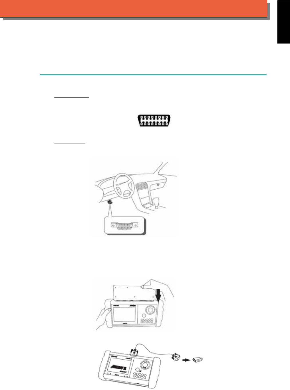
iSCAN-
II
Documentation
SAAB
®
DIAGNOSTIC SYSTEM
GETTING STARTED
1. FIND THE DIAGNOSTIC SOCKET
OBD-
II Soc ket
Most OBD-II diagnostic socket can be found under the dashboard on driver side and are
covered by a plastic cover.
OBD-II socket
Other Soc ket
iSCAN-II SAAB Diagnostic Software does not support the vehicles which are equipped with the
other sockets.
2. SELECT THE INTERFACE MODULE
There is only one interface module available for SAAB diagnostic system, OBDII-IM5. Insert the
interface module into the base unit firmly if the socket in the vehicle is OBD-II, and connect the
adapter that corresponds to the socket, OBDII-AC-16P.
iSCAN-II for SAAB © 2008 Autoland Scientech. Page 1
AUT
LAND
®
SCIENTECH
SAAB
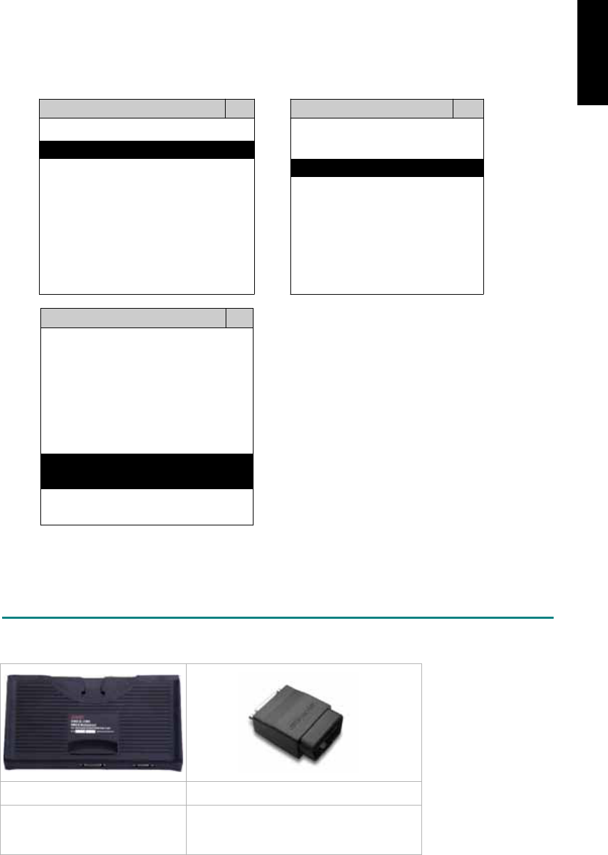
3. CONNECT TO THE VEHICLE
Plug the available diagnostic adapter into the diangostic socket in the vehicle. Select the SAAB
from the screen of iSCAN-II . Press ENTER to start to diagnostic function. If the model is not
listed on the screen, try to press RIGHT / LEFT buttons to turn the page.
MAIN MENU
Vehicle Diagnostic
1 Vehicle Diagnostic 1 <ASIAN>
2 IMS
2
(Interface Module 2 <EUROPEAN>
Simulation System)
3 Component Test System
10 OBDII Standard Compliant
iSCAN-II(V1.00)
20 SETUP
<EUROPEAN>
1 <BMW GT2>
2 <FRENCH PKG>
3 MB
iSCAN-II (V1.00)
4. FIAT
iSCAN-II (V1.00)
5. SAAB
iSCAN-II (V1.00)
6. LANDROVER
iSCAN-II (V1.00)
The figure is for reference only. Autoland Scientech updates the software very often. The
screen shown may not be the same as the newest software delivered.
ADAPTERS AND INTERFACE MODULE
There is only one interface module available for the diagnostic system, OBDII-IM5.
OBD
II
-IM5 OBD
II
-AC-16P
Insert this interface module for
the models equipped with only
OBD-II socket.
The most common adapter for the new
models. Connect to the OBDII-IM5 with
AC-EC1.
There are some adapters available. Refer to the “Diagnostic Cable Connection Quick Manual” for more
detailed connection / wiring information.
iSCAN-II for SAAB © 2008 Autoland Scientech. Page 2
SAAB

START TO DIAGNOSE
Select SAAB by pressing the ENTER button. Turn ignition ON or make engine running at idle.
WARNING! Ignition ON without engine running may have a flat battery.
Select the system from the screen. There may be many systems on the vehicle, try to press RIGHT
button to turn the page. If the ECU response is successful, the screen will show all the available
functions.
SAAB TRANSMISSION
1 ENGINE 1 ID CODES
2 TRANSMISSION 2 READ FAULT CODE
3 ABS
4 SRS
3 CLEAR FAULT CODE
4 DATA STREAM
The figure is for reference only. Autoland Scientech updates the software very often. The screen
shown may not be the same as the newest software delivered. We may simplify the steps of the
procedure.
Autoland Scientech will keep updating the diagnostic software for SAAB. Please refer to the software
specification.
Visit our website, http://www.autolandscientech.com , and apply for membership. You will get E-paper
every month and find more diagnostic technical information.
iSCAN-II for SAAB © 2008 Autoland Scientech. Page 3
SAAB

TROUBLE SHOOTING
iSCAN-
II
never shows anything on LCD screen and there’s no back-light?
1. Please check the cable and the connector again.
2. The voltage of the battery should be higher than 10V.
3. Check the power from OBD-II connector. PIN-16 is power, PIN-4 or PIN-5 is ground.
4. Check fuses in BU-EC (25-Pin Base Unit Extension Cable).
iSCAN-
II
never shows anything on LCD screen and the back-light is ON?
1. Check the diagnostic software using iSCAN-II/PSModule3 File Manager from PC. The
software for iSCAN-II may be missing or broken.
2. Adjust the brightness dial for the LCD panel. The brightness may be too dark.
Can't find the system on the screen?
1. Press Right button for more systems. There are too many systems which can't be shown
on the same page.
2. The diagnostic software does not have this system. Please refer to the specification. We
apologize for the inconvenience.
The green or yellow LED flashed on for a while then showed 'CONNECTION FAILED'
on the LCD screen?
1. Make sure the ignition is ON or make the engine running at idle.
2. Ignition OFF for a while, then Ignition ON and try again.
3. Check the cable and the adapter. Unplug all cables and adapters and plug-in again.
4. Make sure the vehicle equips with the correct system. For example, the manual
transmission will not have A/T transmission ECU.
5. The vehicle will NOT equip with all the systems listed on the software. Some special
systems are only available on the luxury models.
6. The ECU is malfunction or the diagnostic line from the ECU is open or short to the ground or
power.
7. Battery voltage is too low.
Successfully connected to the system but shows 'VERSION UNKNOWN' on the LCD
screen?
Due to the prompt development of the Motor manufactures, the diagnostic software might not
be able to communicate with all ECU versions. Download the newest software from the member
area of Autoland Scientech website and try again. (http://www.autolandscientech.com)
If the same situation occurs, please report the information of ID pages to our local distributors.
We will keep updating the diagnostic software for new ECUs. Please excuse any inconvenience
this may cause.
Successfully connect to the system but show 'LINK FAILURE' on the title?
Some ECUs are not as stable as our research department expected. Please report the
information of ID pages to our local distributors. Our R/D department will do our best to fix the
problems as soon as possible. Please excuse any inconvenience this may cause.
Document Version 1.00 for iSCAN-II, © 2008 Autoland Scientech
The information contained herein is the exclusive property of Autoland Scientech
®
and shall not be distributed, reproduced, or disclosed
in whole or in part without prior written permission of Autoland Scientech
®
. Autoland Scientech
®
reserves the right to make any change
without notice. The trademarks mentioned belong to the owners.
iSCAN-II for SAAB © 2008 Autoland Scientech. Page 4
SAAB

iSCAN-
II
Documentation
SMART
®
DIAGNOSTIC SYSTEM
GETTING STARTED
1. FIND THE DIAGNOSTIC SOCKET
OBD-
II Soc ket
Most OBD-II diagnostic socket can be found under the dashboard on driver side and are
covered by a plastic cover.
OBD-II socket
Other Soc ket
iSCAN-II SMART Diagnostic Software does not support the vehicles which are equipped with
the other sockets.
2. SELECT THE INTERFACE MODULE
There is only one interface module available for SMART diagnostic system, OBDII-IM5. Insert
the interface module into the base unit firmly if the socket in the vehicle is OBD-II, and connect
the adapter that corresponds to the socket, OBDII-AC-16P.
iSCAN-II for SMART © 2008 Autoland Scientech. Page 1
AUT
LAND
®
SCIENTECH
SMART
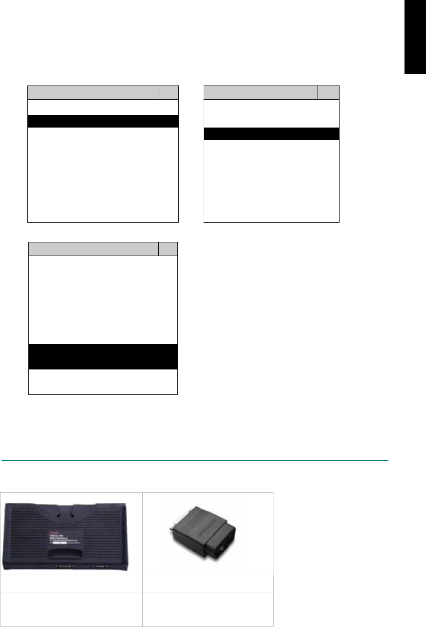
3. CONNECT TO THE VEHICLE
Plug the available diagnostic adapter into the diagnostic socket in the vehicle. Select the
SMART from the screen of iSCAN-II . Press ENTER to start to diagnostic function. If the model
is not listed on the screen, try to press RIGHT / LEFT buttons to turn the page.
MAIN MENU
Vehicle Diagnostic
1 Vehicle Diagnostic 1 <ASIAN>
2 IMS
2
(Interface Module 2 <EUROPEAN>
Simulation System)
3 Component Test System
10 OBDII Standard Compliant
iSCAN-II(V1.00)
20 SETUP
<EUROPEAN>
1 <BMW GT2>
2 <FRENCH PKG>
3 MB
iSCAN-II (V1.00)
4. FIAT
iSCAN-II (V1.00)
5. SMART
iSCAN-II (V1.00)
6. LANDROVER
iSCAN-II (V1.00)
The figure is for reference only. Autoland Scientech updates the software very often. The
screen shown may not be the same as the newest software delivered.
ADAPTERS AND INTERFACE MODULE
There is only one interface module available for the diagnostic system, OBDII-IM5.
OBD
II
-IM5 OBD
II
-AC-16P
Insert this interface module for the
models equipped with only OBD-II
socket.
The most common adapter for
the new models. Connect to the
OBDII-IM5 with AC-EC1.
There are some adapters available. Refer to the “Diagnostic Cable Connection Quick Manual” for more
detailed connection / wiring information.
iSCAN-II for SMART © 2008 Autoland Scientech. Page 2
SMART

START TO DIAGNOSE
Select SMART by pressing the ENTER button. Turn ignition ON or make engine running at idle.
WARNING! Ignition ON without engine running may have a flat battery.
Select the system from the screen. There may be many systems on the vehicle, try to press RIGHT
button to turn the page. If the ECU response is successful, the screen will show all the available
functions.
SMART TRANSMISSION
1 ENGINE 1 ID CODES
2 TRANSMISSION 2 READ FAULT CODE
3 ABS
4 SRS
3 CLEAR FAULT CODE
4 DATA STREAM
The figure is for reference only. Autoland Scientech updates the software very often. The screen
shown may not be the same as the newest software delivered. We may simplify the steps of the
procedure.
Autoland Scientech will keep updating the diagnostic software for SMART. Please refer to the software
specification.
Visit our website, http://www.autolandscientech.com , and apply for membership. You will get E-paper
every month and find more diagnostic technical information.
iSCAN-II for SMART © 2008 Autoland Scientech. Page 3
SMART
SMART

TROUBLE SHOTTING
iSCAN-
II
never shows anything on LCD screen and there’s no back-light?
1. Please check the cable and the connector again.
2. The voltage of the battery should be higher than 10V.
3. Check the power from OBD-II connector. PIN-16 is power, PIN-4 or PIN-5 is ground.
4. Check fuses in BU-EC (25-Pin Base Unit Extension Cable).
iSCAN-
II
never shows anything on LCD screen and the back-light is ON?
1. Check the diagnostic software using iSCAN-II/PSModule3 File Manager from PC. The
software for iSCAN-II may be missing or broken.
2. Adjust the brightness dial for the LCD panel. The brightness may be too dark.
Can't find the system on the screen?
1. Press Right button for more systems. There are too many systems which can't be shown
on the same page.
2. The diagnostic software does not have this system. Please refer to the specification. We
apologize for the inconvenience.
The green or yellow LED flashed on for a while, then showed 'CONNECTION FAILED'
on the LCD screen?
1. Make sure the ignition is ON or make the engine running at idle.
2. Ignition OFF for a while, then Ignition ON and try again.
3. Check the cable and the adapter. Unplug all cables and adapters and plug-in again.
4. Make sure the vehicle equips with the correct system. For example, the manual
transmission will not have A/T transmission ECU.
5. The vehicle will NOT equip with all the systems listed on the software. Some special
systems are only available on the luxury models.
6. The ECU is malfunction or the diagnostic line from the ECU is open or short to the ground or
power.
7. Battery voltage is too low.
Successfully connected to the system but shows 'VERSION UNKNOWN' on the LCD
screen?
Due to the prompt development of the Motor manufactures, the diagnostic software might not
be able to communicate with all ECU versions. Download the newest software from the member
area of Autoland Scientech website and try again. (http://www.autolandscientech.com)
If the same situation occurs, please report the information of ID pages to our local distributors.
We will keep updating the diagnostic software for new ECUs. Please excuse any inconvenience
this may cause.
Successfully connects to the system but shows 'LINK FAILURE' on the title?
Some ECUs are not as stable as our research department expected. Please report the
information of ID pages to our local distributors. Our R/D department will do our best to fix the
problems as soon as possible. Please excuse any inconvenience this may cause.
Document Version 1.00 for iSCAN-II, © 2008 Autoland Scientech
The information contained herein is the exclusive property of Autoland Scientech
®
and shall not be distributed, reproduced, or disclosed
in whole or in part without prior written permission of Autoland Scientech
®
. Autoland Scientech
®
reserves the right to make any change
without notice. The trademarks mentioned belong to the owners.
iSCAN-II for SMART © 2008 Autoland Scientech. Page 4
SMART
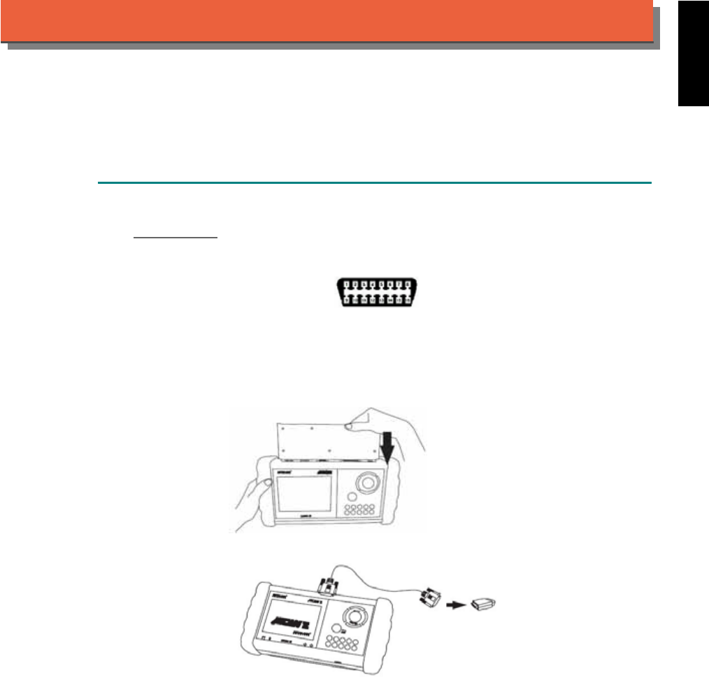
iSCAN-
II
Documentation
SUBARU
®
DIAGNOSTIC SYSTEM
GETTING STARTED
1. FIND THE DIAGNOSTIC SOCKET
OBD-
II Socket
The OBD-II diagnostic socket is located under the steering wheel on driver side.
OBD-II socket
2. SELECT THE INTERFACE MODULE
There is only one interface module available for SUBARU diagnostic system, OBDII-IM5. Insert
the interface module into the base unit firmly. Select the adapter that corresponds to the socket,
ex. OBDII-AC-16P.
iSCAN-II for SUBARU © 2008 Autoland Scientech. Page 1
AUT
LAND
®
SCIENTECH
SUBARU
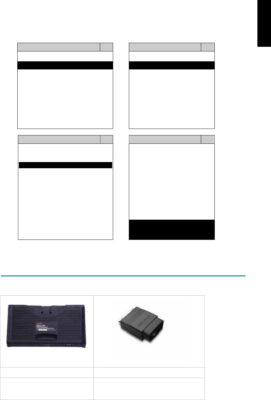
3. CONNECT TO THE VEHICLE
Plug the available diagnostic adapter into the diagnostic socket in the vehicles. Select the
SUBARU from the screen of iSCAN-II . Press ENTER to start the diagnostic function. If the
model is not listed on the screen, try to press RIGHT / LEFT buttons to turn the page.
MAIN MENU
Vehicle Diagnostic
1 Vehicle Diagnostic 1 <ASIAN>
2 IMS
2
(Interface Module 2 <EUROPEAN>
Simulation System)
3 Component Test System
10 OBDII Standard Compliant
iSCAN-II (V1.00)
20 SETUP
<ASIAN>
<JAPAN>
1 <KOREA>
2 <JAPAN>
1 DAIHATSU NON-CAN
iSCAN-II (V1.00)
3 CHRYSLER
iSCAN-II (V1.00)
4 FORD OEM(OBDII 95~)
2 DAIHATSU CAN
iSCAN-II (V1.00)
3
HONDA
MAZDA OEM(OBDII 01~)
iSCAN-II (V1.00)
5. GM US
iSCAN-II (V1.00)
4 ACURA
iSCAN-II (V1.00)
iSCAN-II (V1.00) 5 SUBARU
iSCAN-II (V1.00)
The figure is for reference only. Autoland Scientech updates the software very often. The
screen shown may not be the same as the newest software delivered.
ADAPTERS AND INTERFACE MODULE
There is only one interface module available for the diagnostic system, OBDII-IM5.
OBD
II
-IM5 OBD
II
-AC-16P
OBD-II Full Specification Multiplexer The most common adapter for the new
models. Connect to the OBDII-IM5 with AC-
EC1.
There are some adapters available. Refer to the “Diagnostic Cable Connection Quick Manual” for more
detailed connection / wiring information.
iSCAN-II for SUBARU © 2008 Autoland Scientech. Page 2
SUBARU
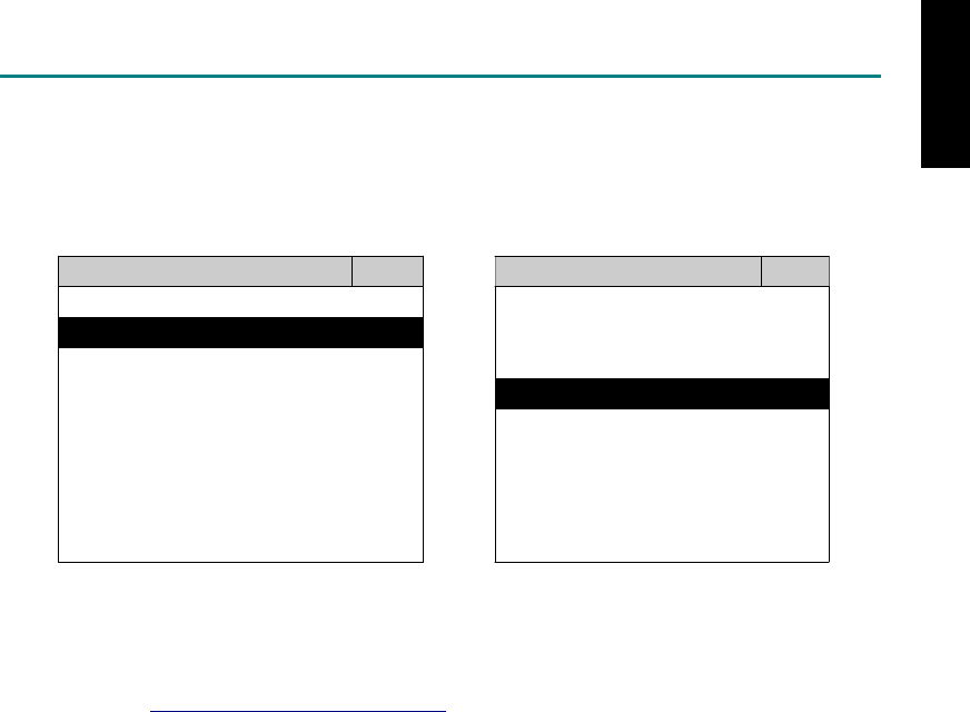
START TO DIAGNOSE
Select SUBARU by pressing the ENTER button. Turn ignition ON or make engine running at idle.
WARNING! Ignition ON without engine running may have a flat battery.
Select the system from the screen. There may be many systems on the vehicle, try to press RIGHT
button to turn the page. If the ECU response is successful, the screen will show all the available
functions.
SUBARU ENGINE
1 ENGINE 1 ID CODES
2 A/T 2 READ FAULT CODE
3 ABS
4 SRS
3 CLEAR FAULT CODE
4 DATA STREAM
The figure is for reference only. Autoland Scientech updates the software very often. The screen
shown may not be the same as the newest software delivered.
Autoland Scientech will keep updating the diagnostic software for SUBARU. Please refer to the
software specification.
Visit our website, http://www.autolandscientech.com , and apply for membership. You will get E-paper
every month and find more diagnostic technical information.
iSCAN-II for SUBARU © 2008 Autoland Scientech. Page 3
SUBARU

TROUBLE SHOOTING
iSCAN-
II
never shows anything on LCD screen and there's no back-light?
1. Please check the cable and the connector again.
2. The voltage of the battery should be higher than 10V.
3. Check the power from OBD-II connector. PIN-16 is power, PIN-4 or PIN-5 is ground.
4. Check fuses in BU-EC (25-Pin Base Unit Extension Cable).
iSCAN-
II
never shows anything on LCD screen and the back-light is ON?
1. Check the diagnostic software using iSCAN-II/PSModule3 File Manager from PC. The
software for iSCAN-II may be missing or broken.
2. Adjust the brightness dial for the LCD panel. The brightness may be too dark.
Can't find the system on the screen?
1. Press Right button for more systems. There are too many systems which can't be shown
on the same page.
2. The diagnostic software does not have this system. Please refer to the specification. We
apologize for the inconvenience.
The green or yellow LED flashed on for a while, then showed 'CONNECTION FAILED'
on the LCD screen?
1. Make sure the ignition is ON or make the engine running at idle.
2. Ignition OFF for a while, then Ignition ON and try again.
3. Check the cable and the adapter. Unplug all cables and adapters and plug-in again.
4. Make sure the vehicle equips with the correct system. For example, the manual
transmission will not have A/T transmission ECU.
5. The vehicle will NOT equip with all the systems listed on the software. Some special
systems are only available on the luxury models.
6. The ECU is malfunction or the diagnostic line from the ECU is open or short to the ground or
power.
7. Battery voltage is too low.
Successfully connected to the system but shows 'VERSION UNKNOWN' on the LCD
screen?
Due to the prompt development of the Motor manufactures, the diagnostic software might not
be able to communicate with all ECU versions. Download the newest software from the member
area of Autoland Scientech website and try again. (http://www.autolandscientech.com)
If the same situation occurs, please report the information of ID pages to our local distributors.
We will keep updating the diagnostic software for new ECUs. Please excuse any inconvenience
this may cause.
Successfully connects to the system but shows 'LINK FAILURE' on the title?
Some ECUs are not as stable as our research department expected. Please report the
information of ID pages to our local distributors. Our R/D department will do our best to fix the
problems as soon as possible. Please excuse any inconvenience this may cause.
Document Version 1.00 for iSCAN-II, © 2008 Autoland Scientech
The information contained herein is the exclusive property of Autoland Scientech
®
and shall not be distributed, reproduced, or disclosed
in whole or in part without prior written permission of Autoland Scientech
®
. Autoland Scientech
®
reserve the right to make any change
without notice. The trademarks mentioned belong to the owners.
iSCAN-II for SUBARU © 2008 Autoland Scientech. Page 4
SUBARU
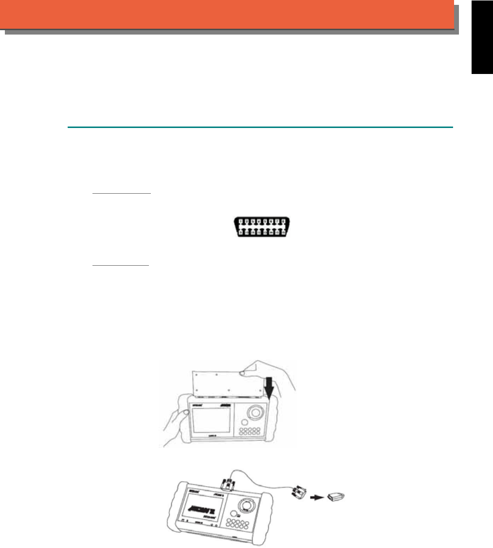
iSCAN-
II
Documentation
SUZUKI
®
DIAGNOSTIC SYSTEM
GETTING STARTED
1. FIND THE DIAGNOSTIC SOCKET
There are two kinds of diagnostic sockets for SUZUKI diagnostic system. Please note that prior
to the year 1998, most vehicles are equipped with 12-Pin socket.
OBD- II Socket
Most OBD-II diagnostic sockets are located under the steering wheel on driver side.
OBD-II socket
12-PIN Soc ket
For the old models equipped with 12-PIN socket, please refer to the sticker direction under the
dashboard on driver side and near the steering column.
2. SELECT THE INTERFACE MODULE
There is only one interface module available for SUZUKI diagnostic system, OBDII-IM5. Insert
the interface module into the base unit firmly. Select the adapter that corresponds to the socket,
ex. OBDII-AC-16P.
iSCAN-II for SUZUKI © 2008 Autoland Scientech. Page 1
AUT
LAND
®
SCIENTECH
SUZUKI
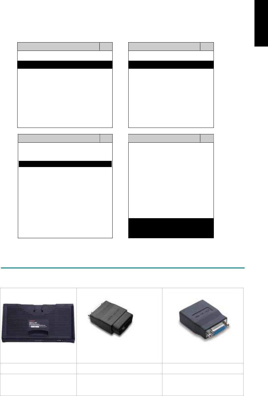
3. CONNECT TO THE VEHICLE
Plug the available diagnostic adapter into the diagnostic socket in the vehicles. Select the
SUZUKI from the screen of iSCAN-II . Press ENTER to start the diagnostic function. If the model
is not listed on the screen, try to press RIGHT / LEFT buttons to turn the page.
MAIN MENU
Vehicle Diagnostic
1 Vehicle Diagnostic 1 <ASIAN>
2 IMS
2
(Interface Module 2 <EUROPEAN>
Simulation System)
3 Component Test System
10 OBDII Standard Compliant
iSCAN-II (V1.00)
20 SETUP
<ASIAN>
<JAPAN>
1 <KOREA>
2 <JAPAN>
1 DAIHATSU NON-CAN
iSCAN-II (V1.00)
3 CHRYSLER
iSCAN-II (V1.00)
4 FORD OEM(OBDII 95~)
2 DAIHATSU CAN
iSCAN-II (V1.00)
3
HONDA
MAZDA OEM(OBDII 01~)
iSCAN-II (V1.00)
5. GM US
iSCAN-II (V1.00)
4 ACURA
iSCAN-II (V1.00)
iSCAN-II (V1.00) 5 SUZUKI
iSCAN-II (V1.00)
The figure is for reference only. Autoland Scientech updates the software very often. The
screen shown may not be the same as the newest software delivered.
ADAPTERS AND INTERFACE MODULE
There is only one interface module available for the diagnostic system, OBDII-IM5.
OBD
II
-IM5 OBD
II
-AC-16P GM-AC-12P
OBD-II Full Specification
Multiplexer
The most common adapter for the
new models. Connect to the
OBDII-IM5 with AC-EC1.
The adapter for the old models.
There are some adapters available. Refer to the “Diagnostic Cable Connection Quick Manual” for more
detailed connection / wiring information.
iSCAN-II for SUZUKI © 2008 Autoland Scientech. Page 2
SUZUKI

START TO DIAGNOSE
Select SUZUKI by pressing the ENTER button. Turn ignition ON or make engine running at idle.
WARNING! Ignition ON without engine running may have a flat battery.
Select the system from the screen. There may be many systems on the vehicle, try to press RIGHT
button to turn the page. If the ECU response is successful, the screen will show all the available
functions.
SUZUKI ENGINE
1 ENGINE 1 ID CODES
2 A/T 2 READ FAULT CODE
3 ABS
4 SRS
5 EPS
3 CLEAR FAULT CODE
4 DATA STREAM
The figure is for reference only. Autoland Scientech updates the software very often. The screen
shown may not be the same as the newest software delivered.
Autoland Scientech will keep updating the diagnostic software for SUZUKI. Please refer to the software
specification.
Visit our website, http://www.autolandscientech.com , and apply for membership. You will get E-paper
every month and find more diagnostic technical information.
iSCAN-II for SUZUKI © 2008 Autoland Scientech. Page 3
SUZUKI
SUZUKI

TROUBLE SHOOTING
iSCAN-
II
never shows anything on LCD screen and there's no back-light?
1. Please check the cable and the connector again.
2. The voltage of the battery should be higher than 10V.
3. Check the power from OBD-II connector. PIN-16 is power, PIN-4 or PIN-5 is ground.
4. Check fuses in BU-EC (25-Pin Base Unit Extension Cable).
iSCAN-
II
never shows anything on LCD screen and the back-light is ON?
1. Check the diagnostic software using iSCAN-II/PSModule3 File Manager from PC. The
software for iSCAN-II may be missing or broken.
2. Adjust the brightness dial for the LCD panel. The brightness may be too dark.
Can't find the system on the screen?
1. Press Right button for more systems. There are too many systems which can't be shown
on the same page.
2. The diagnostic software does not have this system. Please refer to the specification. We
apologize for the inconvenience.
The green or yellow LED flashed on for a while, then showed 'CONNECTION FAILED'
on the LCD screen?
1. Make sure the ignition is ON or make the engine running at idle.
2. Ignition OFF for a while, then Ignition ON and try again.
3. Check the cable and the adapter. Unplug all cables and adapters and plug-in again.
4. Make sure the vehicle equips with the correct system. For example, the manual
transmission will not have A/T transmission ECU.
5. The vehicle will NOT equip with all the systems listed on the software. Some special
systems are only available on the luxury models.
6. The ECU is malfunction or the diagnostic line from the ECU is open or short to the ground or
power.
7. Battery voltage is too low.
Successfully connected to the system but shows 'VERSION UNKNOWN' on the LCD
screen?
Due to the prompt development of the Motor manufactures, the diagnostic software might not
be able to communicate with all ECU versions. Download the newest software from the member
area of Autoland Scientech website and try again. (http://www.autolandscientech.com)
If the same situation occurs, please report the information of ID pages to our local distributors.
We will keep updating the diagnostic software for new ECUs. Please excuse any inconvenience
this may cause.
Successfully connects to the system but shows 'LINK FAILURE' on the title?
Some ECUs are not as stable as our research department expected. Please report the
information of ID pages to our local distributors. Our R/D department will do our best to fix the
problems as soon as possible. Please excuse any inconvenience this may cause.
Document Version 1.00 for iSCAN-II, © 2008 Autoland Scientech
The information contained herein is the exclusive property of Autoland Scientech
®
and shall not be distributed, reproduced, or disclosed
in whole or in part without prior written permission of Autoland Scientech
®
. Autoland Scientech
®
reserve the right to make any change
without notice. The trademarks mentioned belong to the owners.
iSCAN-II for SUZUKI © 2008 Autoland Scientech. Page 4
SUZUKI
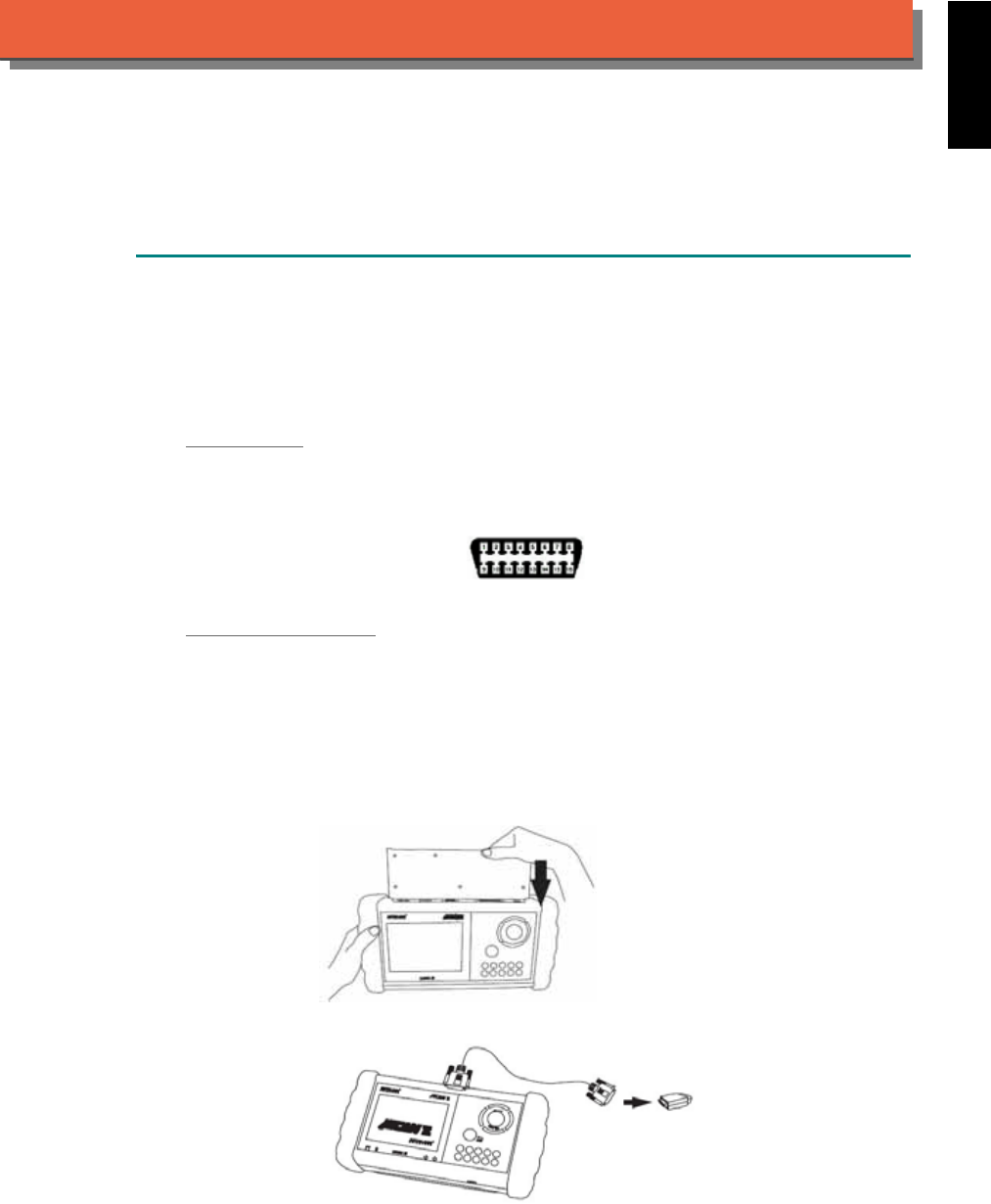
iSCAN-
II
Documentation
VASS
®
DIAGNOSTIC SYSTEM
GETTING STARTED
VASS means Volkswagen, Audi, Seat, Skoda (the Volkswagen groups).
1. FIND THE DIAGNOSTIC SOCKET
There are two kinds of diagnostic sockets for VASS diagnostic system. Please note that prior to
the year 1995, most vehicles were equipped with black/white socket under the engine hood.
OBD- II Soc ket
For the newer models, OBD-II diagnostic socket can be found under the dashboard on driver
side and are covered by a plastic cover. For old models equipped with OBD-II socket, the
location may be different.
OBD-II socket
BLACK / WHITE Soc ket
BLACK / WHITE diagnostic socket can be found in the engine compartment beside the driver
side. Or near the absorber strut tower on the either side of driver and passenger.
2. SELECT THE INTERFACE MODULE
There is only one interface module available for VASS diagnostic system, OBDII-IM5. Insert the
interface module into the base unit firmly if the socket in the vehicle is OBD-II, and connect the
adapter that corresponds to the socket, OBDII-AC-16P.
iSCAN-II for VASS © 2008 Autoland Scientech. Page 1
AUT
LAND
®
SCIENTECH
VASS
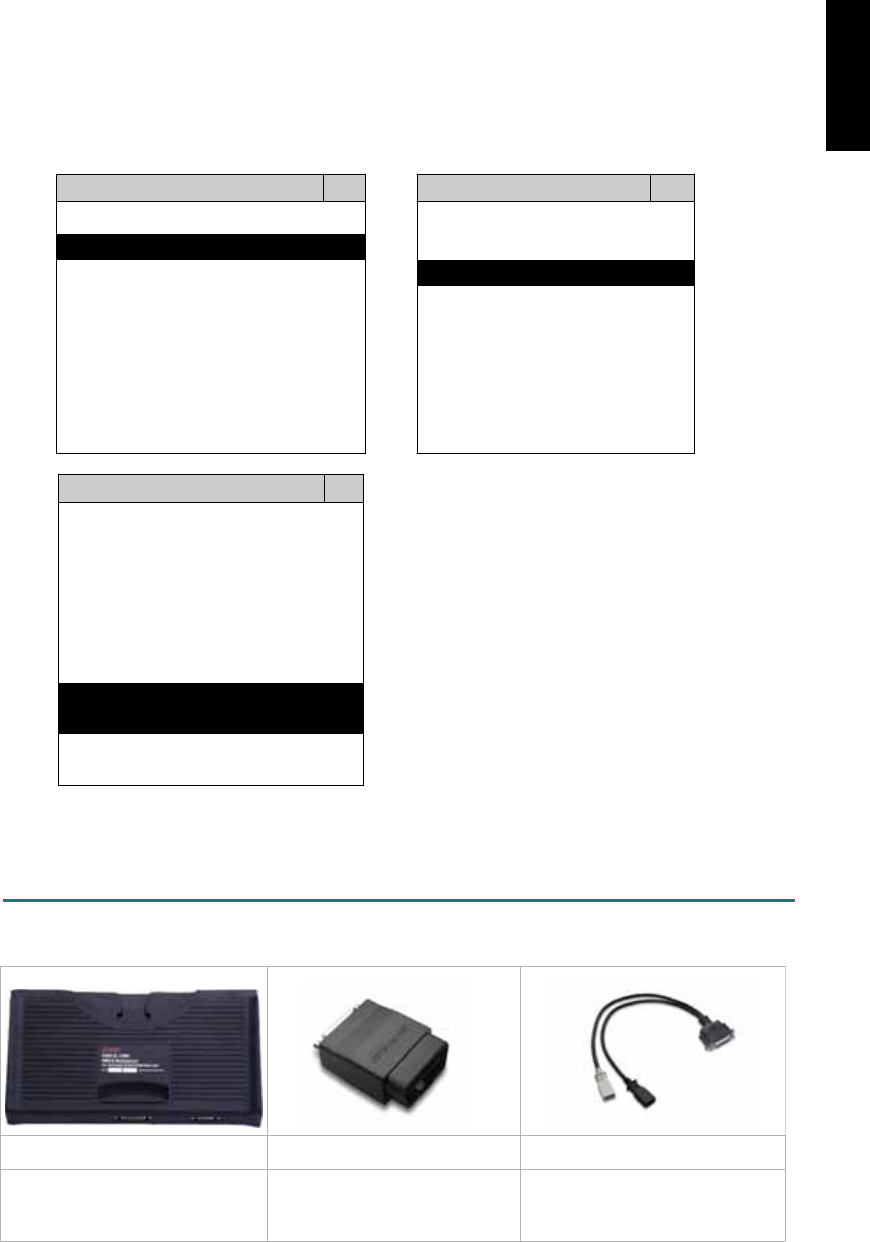
3. CONNECT TO THE VEHICLE
Plug the available diagnostic adapter into the diagnostic socket in the vehicle. Select the VASS
from the screen of iSCAN-II . Press ENTER to start to diagnostic function. If the model is not
listed on the screen, try to press RIGHT / LEFT buttons to turn the page.
MAIN MENU
Vehicle Diagnostic
1 Vehicle Diagnostic 1 <ASIAN>
2 IMS
2
(Interface Module 2 <EUROPEAN>
Simulation System)
3 Component Test System
10 OBDII Standard Compliant
iSCAN-II(V1.00)
20 SETUP
<EUROPEAN>
1 <BMW GT2>
2 <FRENCH PKG>
3 MB
iSCAN-II (V1.00)
4. FIAT
iSCAN-II (V1.00)
5. VASS
iSCAN-II (V1.00)
6. LANDROVER
iSCAN-II (V1.00)
The figure is for reference only. Autoland Scientech updates the software very often. The
screen shown may not be the same as the newest software delivered.
ADAPTERS AND INTERFACE MODULE
There is only one interface module available for the diagnostic system, OBDII-IM5.
OBD
II
-IM5 OBD
II
-AC-16P VASS-C
Insert this interface module for
the models equipped with only
OBD-II socket.
The most common adapter for
the new models. Connect to
the OBDII-IM5 with AC-EC1.
The adapter for the old models.
Connect to the OBDII-IM5 with
AC-EC1.
There are some adapters available. Refer to the “Diagnostic Cable Connection Quick Manual” for more
detailed connection / wiring information.
iSCAN-II for VASS © 2008 Autoland Scientech. Page 2
VASS

START TO DIAGNOSE
Select VASS by pressing the ENTER button. Turn ignition ON or make engine running at idle.
WARNING! Ignition ON without engine running may have a flat battery.
Select the system from the screen. There may be many systems on the vehicle, try to press RIGHT
button to turn the page. If the ECU response is successful, the screen will show all the available
functions.
AUDI En
g
ine
1 Power Train 1 ID CODES
2 Chassis 2 READ FAULT CODE
3 Bod
y
4 Information and
Communication
3 CLEAR FAULT CODE
4 DATA STREAM
5 BASIC SETTING
5 Air condition 6 ADAPTATION
The figure is for reference only. Autoland Scientech updates the software very often. The screen
shown may not be the same as the newest software delivered.
Autoland Scientech will keep updating the diagnostic software for VASS. Please refer to the software
specification.
Visit our website, http://www.autolandscientech.com , and apply for membership. You will get E-paper
every month and find more diagnostic technical information.
iSCAN-II for VASS © 2008 Autoland Scientech. Page 3
VASS

TROUBLE SHOOTING
iSCAN-
II
never shows anything on LCD screen and there’s no back-light?
1. Please check the cable and the connector again.
2. The voltage of the battery should be higher than 10V.
3. Check the power from OBD-II connector. PIN-16 is power, PIN-4 or PIN-5 is ground.
4. Check fuses in BU-EC (25-Pin Base Unit Extension Cable).
iSCAN-
II
never shows anything on LCD screen and the back-light is ON?
1. Check the diagnostic software using iSCAN-II/PSModule3 File Manager from PC. The
software for iSCAN-II may be missing or broken.
2. Adjust the brightness dial for the LCD panel. The brightness may be too dark.
Can't find the system on the screen?
1. Press Right button for more systems. There are too many systems which can't be shown
on the same page.
2. The diagnostic software does not have this system. Please refer to the specification. We
apologize for the inconvenience.
The green or yellow LED flashed on for a while, then showed 'CONNECTION FAILED'
on the LCD screen?
1. Make sure the ignition is ON or make the engine running at idle.
2. Ignition OFF for a while, then Ignition ON and try again.
3. Check the cable and the adapter. Unplug all cables and adapters and plug-in again.
4. Make sure the vehicle equips with the correct system. For example, the manual
transmission will not have A/T transmission ECU.
5. The vehicle will NOT equip with all the systems listed on the software. Some special
systems are only available on the luxury models.
6. The ECU is malfunction or the diagnostic line from the ECU is open or short to the ground or
power.
7. Battery voltage is too low.
Successfully connected to the system but shows 'VERSION UNKNOWN' on the LCD
screen?
Due to the prompt development of the Motor manufactures, the diagnostic software might not
be able to communicate with all ECU versions. Download the newest software from the member
area of Autoland Scientech website and try again. (http://www.autolandscientech.com)
If the same situation occurs, please report the information of ID pages to our local distributors.
We will keep updating the diagnostic software for new ECUs. Please excuse any inconvenience
this may cause.
Successfully connects to the system but shows 'LINK FAILURE' on the title?
Some ECUs are not as stable as our research department expected. Please report the
information of ID pages to our local distributors. Our R/D department will do our best to fix the
problems as soon as possible. Please excuse any inconvenience this may cause.
Document Version 1.00 for iSCAN-II, © 2008 Autoland Scientech
The information contained herein is the exclusive property of Autoland Scientech
®
and shall not be distributed, reproduced, or disclosed
in whole or in part without prior written permission of Autoland Scientech
®
. Autoland Scientech
®
reserves the right to make any change
without notice. The trademarks mentioned belong to the owners.
iSCAN-II for VASS © 2008 Autoland Scientech. Page 4
VASS
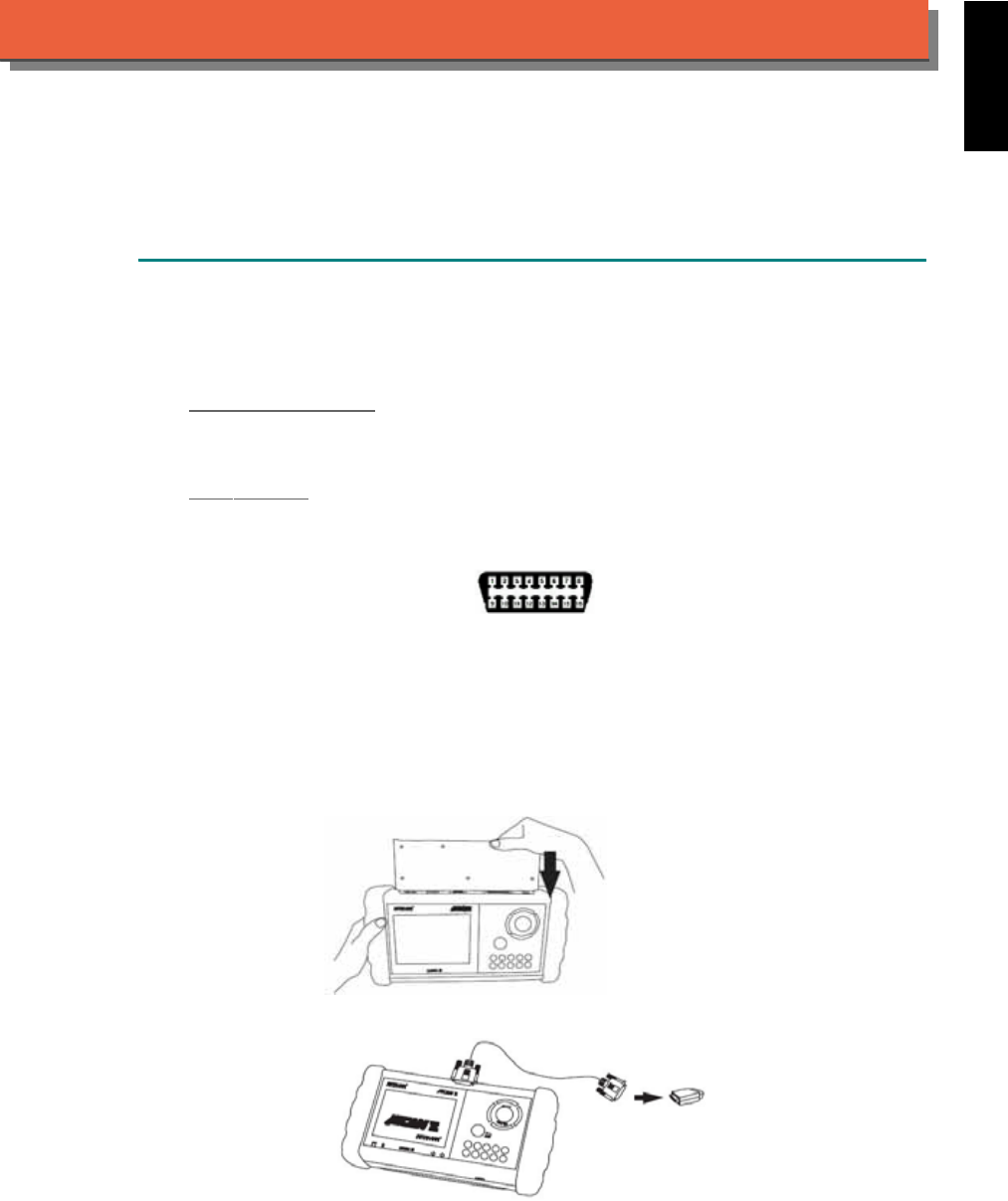
iSCAN-
II
Documentation
VOLVO
®
DIAGNOSTIC SYSTEM
GETTING STARTED
1. FIND THE DIAGNOSTIC SOCKET
There are two kinds of diagnostic sockets for VOLVO diagnostic system. Please note that prior
to the year 1997 most vehicles were equipped with AB-diagnostic socket under the engine
hood.
A/B Diagnostic Socket
For the models 700/800/900 Series, between year 1989 to 1996, A/B diagnostic socket can be
found in the engine compartment, behind the driver side or passenger side absorber strut tower.
OBD- II Socket
For the newer models, ex. S70 / S80 / XC90...etc, OBD-II diagnostic socket can be found under
the dashboard on driver side and are covered by a plastic cover. It is very close to side kicker
and near the door.
OBD-II socket
2. SELECT THE INTERFACE MODULE
There is only one interface module available for VOLVO diagnostic system, OBDII-IM5. Insert
the interface module into the base unit firmly if the socket in the vehicle is OBD-II, and connect
the adapter that corresponds to the socket, OBDII-AC-16P. Do NOT insert any interface
module for old models equipped with AB-diagnostic socket.
iSCAN-II for VOLVO © 2008 Autoland Scientech. Page 1
AUT
LAND
®
SCIENTECH
VOLVO
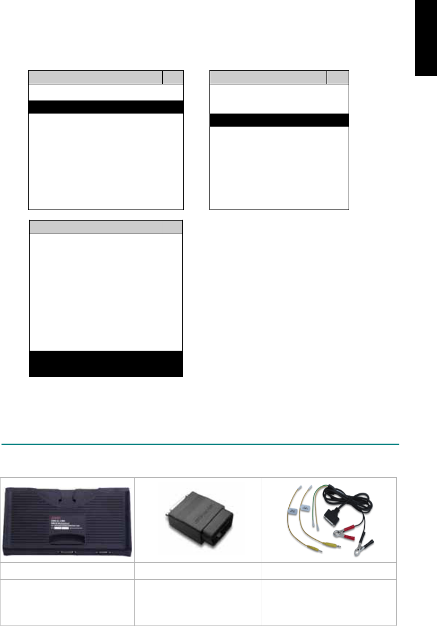
3. CONNECT TO THE VEHICLE
Plug the available diagnostic adapter into the diagnostic socket at the vehicles. Select the
VOLVO from the screen in iSCAN-II. Press ENTER to start to diagnose. If the models are not
listed in the screen, try to press RIGHT / LEFT buttons to find more models.
MAIN MENU
Vehicle Diagnostic
1 Vehicle Diagnostic 1 <ASIAN>
2 IMS
2
(Interface Module 2 <EUROPEAN>
Simulation System)
3 Component Test System
10 OBDII Standard Compliant
iSCAN-II (V1.00)
20 SETUP
<EUROPEAN>
1 <BMW GT2>
2 <FRENCH PKG>
3 MB
iSCAN-II (V1.00)
4. FIAT
iSCAN-II (V1.00)
5. JAGUAR
iSCAN-II (V1.00)
6. VOLVO
iSCAN-II (V1.00)
The figure is for reference only. Autoland Scientech updates the software very often. The
screen shown may not be the same as the newest software delivered.
ADAPTERS AND INTERFACE MODULE
There is only one interface module available for the diagnostic system, OBDII-IM5.
OBD
II
-IM5 OBD
II
-AC-16P D51-C-MBLV
Insert this interface module for
the models equipped with only
OBD-II socket.
The most common adapter for
the new models. Connect to
the OBDII-IM5 with AC-EC1.
MB 8/16-pin and Volvo A/B
connectors. The adapter for the
old models. Connect directly to
iSCAN-II using BU-EC.
There are some adapters available. Refer to the “Diagnostic Cable Connection Quick Manual” for more
detailed connection / wiring information.
iSCAN-II for VOLVO © 2008 Autoland Scientech. Page 2
VOLVO

START TO DIAGNOSE
Select VOLVO by pressing the ENTER button. Turn ignition ON or make engine running at idle.
WARNING! Ignition ON without engine running may have a flat battery.
Select the system from the screen. There may be many systems on the vehicle, try to press RIGHT
button to turn the page. If the ECU response is successful, the screen will show all the available
functions.
VOLVO XC90
1 Models u
p
to 1997 1 ID CODES
2 Models from 1997 2 READ FAULT CODE
3 CLEAR FAULT CODE
4 DATA STREAM
5 ACTIVATION
6 ADAPTATION
The figure is for reference only. Autoland Scientech updates the software very often. The screen
shown may not be the same as the newest software delivered. We may simplify the steps of the
procedure.
Autoland Scientech will keep updating the diagnostic software for VOLVO. Please refer to the software
specification.
Visit our website, http://www.autolandscientech.com , and apply for membership. You will get E-paper
every month and find more diagnostic technical information.
iSCAN-II for VOLVO © 2008 Autoland Scientech. Page 3
VOLVO
VOLVO

TROUBLE SHOOTING
iSCAN-
II
never shows anything on LCD screen and there’s no back-light?
1. Please check the cable and the connector again.
2. The voltage of the battery should be higher than 10V.
3. Check the power from OBD-II connector. PIN-16 is power, PIN-4 or PIN-5 is ground.
4. Check fuses in BU-EC (25-Pin Base Unit Extension Cable).
iSCAN-
II
never shows anything on LCD screen and the back-light is ON?
1. Check the diagnostic software using iSCAN-II/PSModule3 File Manager from PC. The
software for iSCAN-II may be missing or broken.
2. Adjust the brightness dial for the LCD panel. The brightness may be too dark.
Can't find the system on the screen?
1. Press Right button for more systems. There are too many systems which can't be shown
on the same page.
2. The diagnostic software does not have this system. Please refer to the specification. We
apologize for the inconvenience.
The green or yellow LED flashed on for a while, then showed 'CONNECTION FAILED'
on the LCD screen?
1. Make sure the ignition is ON or make the engine running at idle.
2. Ignition OFF for a while, then Ignition ON and try again.
3. Check the cable and the adapter. Unplug all cables and adapters and plug-in again.
4. Make sure the vehicle equips with the correct system. For example, the manual
transmission will not have A/T transmission ECU.
5. The vehicle will NOT equip with all the systems listed on the software. Some special
systems are only available on the luxury models.
6. The ECU is malfunction or the diagnostic line from the ECU is open or short to the ground or
power.
7. Battery voltage is too low.
Successfully connected to the system but shows 'VERSION UNKNOWN' on the LCD
screen?
Due to the prompt development of the Motor manufactures, the diagnostic software might not
be able to communicate with all ECU versions. Download the newest software from the member
area of Autoland Scientech website and try again. (http://www.autolandscientech.com)
If the same situation occurs, please report the information of ID pages to our local distributors.
We will keep updating the diagnostic software for new ECUs. Please excuse any inconvenience
this may cause.
Successfully connects to the system but shows 'LINK FAILURE' on the title?
Some ECUs are not as stable as our research department expected. Please report the
information of ID pages to our local distributors. Our R/D department will do our best to fix the
problems as soon as possible. Please excuse any inconvenience this may cause.
The ECU successfully responds but the data stream seems wrong?
Try to select OTHER YEARS. VOLVO changes the protocols EVERY year and the manufacture
year may not be the same as the list in the license plate.
For A/B diagnostic sockets: The ECU failed to respond, received fault codes?
For old cars, the ground pin of an A/B diagnostic socket is not so stable. Try to make the ground
pin stable by connect a wire to the battery or polish the ground in the diagnostic socket.
iSCAN-II for VOLVO © 2008 Autoland Scientech. Page 4
VOLVO

Fail to reset the service light for S70 / V70 ?
The service light can not be reset directly. Modify the service time / distance, then reset the
service again.
Document Version 1.00 for iSCAN-II, © 2008 Autoland Scientech
The information contained herein is the exclusive property of Autoland Scientech
®
and shall not be distributed, reproduced, or disclosed
in whole or in part without prior written permission of Autoland Scientech
®
. Autoland Scientech
®
reserves the right to make any change
without notice. The trademarks mentioned belong to the owner.
iSCAN-II for VOLVO © 2008 Autoland Scientech. Page 5
VOLVO

USER’S NOTICE
ACKNOWLEDGMENT
Products referred to in this manual are mentioned for identification purposes only. Product names appearing in this manual
or on the Scanner’s screen may or may not be registered trademarks or copyrights of their respective companies.
ACURA is a registered trademark of Honda Motor Company, Limited.
ALFA ROMEO is a registered trademark of Fiat S.p.A.
AUDI is a registered trademark of AUDI AG.
BENTLEY is a registered trademark of Bentley Motors Limited, Volkswagen AG.
BMW is a registered trademark of Bayerische Motoren Werke AG.
BUICK is a registered trademark of General Motors Corporation.
CADILLAC is a registered trademark of General Motors Corporation.
CHERY is a registered trademark of Chery Automobile Co., Ltd..
CHEVROLET is a registered trademark of General Motors Corporation.
CHRYSLER is a registered trademark of Chrysler LLC.
CITROЁN is a registered trademark of PSA Peugeot Citroën.
DAEWOO is a registered trademark of GM Daewoo Auto & Technology.
DAIHATSU is a registered trademark of GM Daihatsu Motor Company.
DODGE is a registered trademark of Chrysler LLC.
FIAT is a registered trademark of Fiat S.p.A.
FORD is a registered trademark of Ford Motor Company.
GM is a registered trademark of General Motors Corporation.
GMC is a registered trademark of General Motors Corporation.
GREATWALL is a registered trademark of Great Wall Motor Company.
HOLDEN is a registered trademark of GM Holden Ltd.
HONDA is a registered trademark of Honda Motor Company, Limited.
HYUNDAI is a registered trademark of Hyundai Motor Company.
INFINITI is a registered trademark of Nissan Motor Company.
ISUZU is a registered trademark of Isuzu Motors Ltd.
JAGUAR is a registered trademark of Jaguar Cars Limited.
JEEP is a registered trademark of Chrysler LLC.
KIA is a registered trademark of KIA Motors, Hyundai Kia Automotive Group.
LANDROVER is a registered trademark of Premier Automotive Group, Ford Motor Company, and Tata Motors.
LEXUS is a registered trademark of Toyota Motor Corporation.
MAYBACH is a registered trademark of Maybach-Motorenbau GmbH, Daimler AG.
MAZDA is a registered trademark of MAZDA Motor Corporation.
MERCEDES BENZ is a registered trademark of Daimler AG.
MINI is a registered trademark of Bayerische Motoren Werke AG.
MITSUBISHI is a registered trademark of Mitsubishi Motors Corporation.
NISSAN is a registered trademark of Nissan Motor Company.
OLDSMOBILE is a registered trademark of General Motors Corporation.
OPEL is a registered trademark of Adam Opel GmbH, General motors Corporation.
PONTIAC is a registered trademark of General Motors Corporation.
PERODUA is a registered trademark of Perodua Automotive.
PEUGEOT is a registered trademark of PSA Peugeot Citroën.
PORSCHE is a registered trademark of Porsche AG.
PROTON is a registered trademark of Proton Holdings Berhad.
RENAULT is a registered trademark of Renault S.A.
SAAB is a registered trademark of Saab Automobile AB.
SATURN is a registered trademark of Saturn Corporation, General Motors Corporation.
SCION is a registered trademark of Toyota Motor Corporation.
SEAT is a registered trademark of SEAT S.A., Volkswagen Group.
SKODA is a registered trademark of Skoda Auto, Volkswagen Group.
SMART is a registered trademark of Smart GmbH, Daimler AG.
SSANGYONG is a registered trademark of SsangYong Motor Company.
SUBARU is a registered trademark of Fuji Heavy Industries Co., Ltd.
SUZUKI is a registered trademark of SUZUKI Motor Corporation.
TOYOTA is a registered trademark of Toyota Motor Corporation.
VOLKSWAGEN is a registered trademark of Volkswagen AG.
VOLVO is a registered trademark of the Volvo Car Coporation, Ford Motor Company.
SII is a registered trademark of Seiko Instruments Inc.
Microsoft
©
and Windows
©
are registered trademarks of Microsoft Corporation.

COPYRIGHT
This instruction manual and PC Scanner CD-ROM are published by AUTOLAND SCIENTECH
®
and are protected by
copyright and other intellectual property rights in existence at all times and in all territories throughout the world.
Permission is hereby granted to print a hard copy ONLY for the sole purpose of using this as an information resource for
operating products manufactured by AUTOLAND SCIENTECH
®
. No part of this instruction manual or the PC Scanner
software may be reproduced republished or transmitted, in any form or by any means, whether electronic, mechanical,
copied, or otherwise, unless a prior consent from AUTOLAND SCIENTECH
®
has been obtained.
DISCLAIMER AND LIABILITY
The information and illustrations contained in this manual are based on the latest information available at the time of
publication. AUTOLAND SCIENTECH
®
reserves the right to make changes at any time without notice.
This instruction manual tells users how to use the Scanner to perform diagnostic tests and find possible locations of vehicle
problems. It does NOT tell users how to correct the problems. Consult the manufacturer’s vehicle service manual or other
publication for repair instructions.
To make full use of the Scanner’s capabilities, the user should be knowledgeable and well-trained in each of the vehicle
computer control systems described in this manual.
Service data that appear to be non-functional on some vehicles may be due to changes in vehicle manufacturing design. In
addition, AUTOLAND SCIENTECH
®
shall not accept responsibility for any incidental or consequential damages under any
circumstances, in connection with using this instructional manual or PC-Scanner software, nor shall AUTOLAND
SCIENTECH
®
be liable for any errors contained in this instruction manual.
iSCAN-II Manual, Version 1.0
May 2008
© Copyright 1998 by AUTOLAND SCIENTECH
®
Co., Ltd.
All rights reserved
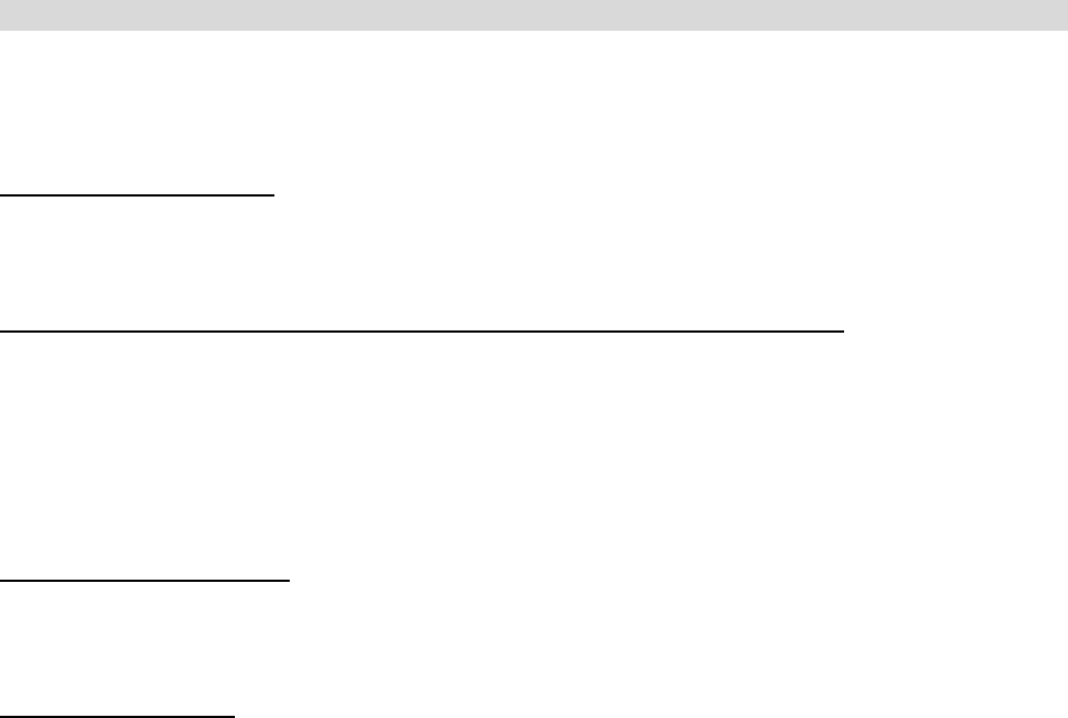
OPERATIONAL GUIDELINES
This section explains crucial operational guidelines that must be observed when using diagnostic tools and memory
cartridges produced by AUTOLAND SCIENTECH
®
. It is important to read these guidelines before operating on a vehicle in
order to avoid any personal injury or damage to the vehicle or diagnostic equipment.
TO AVOLD VOLTAGE SPIKES
To avoid the possible voltage spikes and to protect the vehicle and diagnostic tools from resultant damage, please do not
connect or disconnect the diagnostic tool while the ignition key is ON or while the engine is running.
TURN THE DIAGNOSTIC TOOL OFF WHILE INSERTING/REMOVING MEMORY CARTRIDGE
Please do not insert or remove memory cartridges while the diagnostic tool’s power is ON.
To change a memory cartridge, please follow the steps below:
a. Turn the ignition OFF.
b. Disconnect the diagnostic tool’s power supply source.
c. Change the memory cartridge.
d. Reconnect the diagnostic tool’s power supply source.
e. Turn the ignition ON.
PUT THE PARKING BRAKE ON
In order to avoid personal injury or damage to the vehicle that might result from incorrect operation, please always apply the
parking brake and block the wheels when operating the diagnostic tool.
DANGER! DRIVING TEST
Please DO NOT leave any moving parts below the driving seat. Any moving parts may block the brake pads. The car will
lost control and the drivers will injure if the brake fail. DO NOT drive too quick if the diagnostic connecter is below the engine
hood. Too heavy the wind will open the engine hood because the hood is not proper locked.
Federal Communications Commission (FCC) Statement
15.21
You are cautioned that changes or modifications not expressly approved by the part responsible for
compliance could void the user’s authority to operate the equipment.
15.105(b)
This equipment has been tested and found to comply with the limits for a Class B digital device,
pursuant to part 15 of the FCC rules. These limits are designed to provide reasonable protection
against harmful interference in a residential installation. This equipment generates, uses and can
radiate radio frequency energy and, if not installed and used in accordance with the instructions,
may cause harmful interference to radio communications. However, there is no guarantee that
interference will not occur in a particular installation. If this equipment does cause harmful
interference to radio or television reception, which can be determined by turning the equipment off
and on, the user is encouraged to try to correct the interference by one or more of the following
measures:
-Reorient or relocate the receiving antenna.
-Increase the separation between the equipment and receiver.
-Connect the equipment into an outlet on a circuit different from that to which the receiver is
connected.
-Consult the dealer or an experienced radio/TV technician for help.
Operation is subject to the following two conditions:
1) this device may not cause interference and
2) this device must accept any interference, including interference that may cause undesired
operation of the device.
FCC RF Radiation Exposure Statement:
This equipment complies with FCC radiation exposure limits set forth for an uncontrolled
environment. End users must follow the specific operating instructions for satisfying RF exposure
compliance. This transmitter must not be co-located or operating in conjunction with any other
antenna or transmitter.