AUTOSLIDE AS8 Pedestrian MULTIDRIVE Sliding Door Operator User Manual multidrive installation manual as8
AUTOSLIDE PTY LTD Pedestrian MULTIDRIVE Sliding Door Operator multidrive installation manual as8
User Manual

© 2018 Autoslide Pty Ltd MultiDrive
MultiDrive
TM
Installation instructions

© 2018 Autoslide Pty Ltd MultiDrive 1
WARNING :-
The user of MULTIDRIVE devices must be disconnected from the source of supply before attempting
the installation of the accessory
“ PEDESTRIAN DOOR FOR RESIDENTIAL USE “
The switch is to be install in a location from which operation of the door can be observed by the person
operating the switch
The glazing material employed is to comply with the requirement in UL30.5.1.
The glazing material in both xed and sliding panels of all sliding doors and in all unframed
swinging doors shall comply with the requirements in the Performance Specications and Methods of
Test for Safety Glazing Material Used in Buildings, referenced in Annex A. Ref. No 27. Glazing material for
other pedestrian doors shall also comply with the same standard, except that single strength or heavier
glass may be used for those portions of doors involving a glazed area of less than 0.9m2 ( 1 ft2) and
having no dimension greater than 457mm ( 18 in).
The pedestrian door operator that is intended for connection to the source of supply by a exible is to
be cautious/warn, against risks of associated with allowing the cord to become entrapped in moving
parts of the operator, door, or system
Maximum size of door ; Bi-parting sliding door : ( 2.3 metre height x 4 metre width )
Weight :
singe slide : 150kg mobile leaf,
Bi-parting : 75kg per mobile leaf
The weight is the most concern, if the door is make of light material, door can be made bigger than
4m for bi-parting. As long as the total weight for mobile panel ( total mobile panels weight) does not
exceed 150 kg.
side of the operator, where the 3 pin
AC power supply will be then plug into this socket. Any access wire has to be well tied/ or dressed,
preventing tangling wire .
Note the cord should not be :-
1.
2. Attached or otherwise secured to the building structure ; or
3. Concealed behind walls and the like.
Manufacturer’s Name AUTOSLIDE PTY LTD
Trademark MULTIDRIVE
Catalogue number AS8
Voltage 100VAC-240VAC, OUTPUT: 24VDC , 2.7A
Frequency 50Hz, 60 Hz
Adaptor maximum input current 2.7A
As per 60.1.7 For equipment having a grounding-type attachment plug, the following instructions, or the
equivalent, shall be provided. “ To reduce the risk of electric shock, this equipment has a grounding type plug,
that has a third ( grounding) pin. This plug will only t into a grounding type outlet. If the plug does not t into
the outlet, contact a qualied electrician to install the proper outlet. Do not change the plug in any way. “
Detachable Power Supply Cord Marking- “ WARNING : USE ONLY ADAPTOR PROVIDED FOR USE WITH OPERATOR,
OTHER ADAPTOR MAY RESULT IN RISK OF FIRE. SEE INSTALLATION INSTRUCTIONS FOR DETAIL” or equivalent.
© 2018 Autoslide Pty Ltd MultiDrive 2
Contents
The MultiDrive 3
Repairs and returns 3
Questions and comments 3
Warranty 3
About the MultiDrive 5
What’s included 6,7
Door requirements 8
Sliding door friction 8
Space under the head jamb 8
Coating the cover 9
Installation instructions 10
1. Cut parts to size 10
2. Attach parts to the base 11
3. Attach the base to the door 21
4. Attach the brackets and cover 24
5. Install the mode pad 26
Programming the controller 29
1. Learn wireless inputs 29
2. Set DIP switches 30
3. Set the controller for pets 31
© 2018 Autoslide Pty Ltd MultiDrive <1>
© 2018 Autoslide Pty Ltd MultiDrive 3
The MultiDrive
This document explains how to assemble the MultiDrive automatic door opening
system. It is important to follow these instructions as stated for a correct
installation and full warranty coverage.
Repairs and returns
Email: support@autoslide.com
Web: www.autoslide.com
Phone:
833- 337-5433 (North America)
1 800 600 602 (Australia)
Questions and comments
If you have questions about installation, programming, or operation
of your MultiDrive or about any parts or accessories, email us at
support@autoslide.com or visit us online at autoslide.com.
Warranty
The MultiDrive is produced by Autoslide Pty or Autoslide LLC and
is subject to the following warranty and conditions of operation.
The product is warranted against failure due to faulty material or
workmanship for a period of 24 months from date of supply. .
This warranty will cover the repair or replacement of any defective
parts at an authorized Autoslide Pty or Autoslide LLC facility and is
subject to the following conditions, provided that:
The MultiDrive is installed by an authorized Autoslide Pty or
Autoslide LLC distributor or installation company, and
supplied instructions, and
instructions, and
and
The warranty is limited to an amount totaling no more than the
unit cost price.
This warranty shall be null and void and to no effect if:
The MultiDrive is abused or in any way used outside the limits
The electric wiring has been interfered with and is not wired in
accordance with the original factory settings, or
Defects are not caused by normal wear and tear, or

© 2018 Autoslide Pty Ltd MultiDrive <1>
© 2018 Autoslide Pty Ltd MultiDrive 4
• The purchaser in any way alters the MultiDrive, or adds or
removes parts or materials of the MultiDrive, or
• The purchaser fails to notify Autoslide Pty or Autoslide LLC
immediately if there is a failure of any component.
Conditions:
• Delivery costs of all warranty items will be covered by
purchase. After 90 days, delivery costs of warranty items will
be at the purchaser’s expense.
• The purchaser will be responsible for inspecting the MultiDrive
package to ensure that the package is complete and not
damaged and that all parts are present. If there is damage or
missing pieces, the purchaser must alert Autoslide Pty or
Autoslide LLC within 3 business days of receipt of order.
• Upon installation of the MultiDrive, the buyer shall immediately
notify Autoslide Pty or Autoslide LLC in writing or by phone
about any defect in the goods to obtain a replacement under
warranty.
• In the event a MultiDrive unit is returned to Autoslide Pty or
Autoslide LLC for a warranty claim, the MultiDrive unit must be
received free from damage. It is highly recommended that the
purchaser takes pictures of the MultiDrive system prior to
shipping it back to Autoslide Pty or Autoslide LLC.
• The purchaser expressly acknowledges and agrees that
Autoslide Pty or Autoslide LLC is not liable for any advice
given by its agents in relation to the suitability of the product or
its application to certain doors and such advice is relied upon
at the purchaser’s risk.
• The buyer shall not carry out any remedial work on the alleged
instruction from Autoslide Pty or Autoslide LLC.
• The warranty on any battery is subject to the warranty provided
by the original manufacturer of the battery. Thus said warranty
is two years from date of purchase.
© 2018 Autoslide Pty Ltd MultiDrive <1>
© 2018 Autoslide Pty Ltd MultiDrive 5
c) d)
a) b)
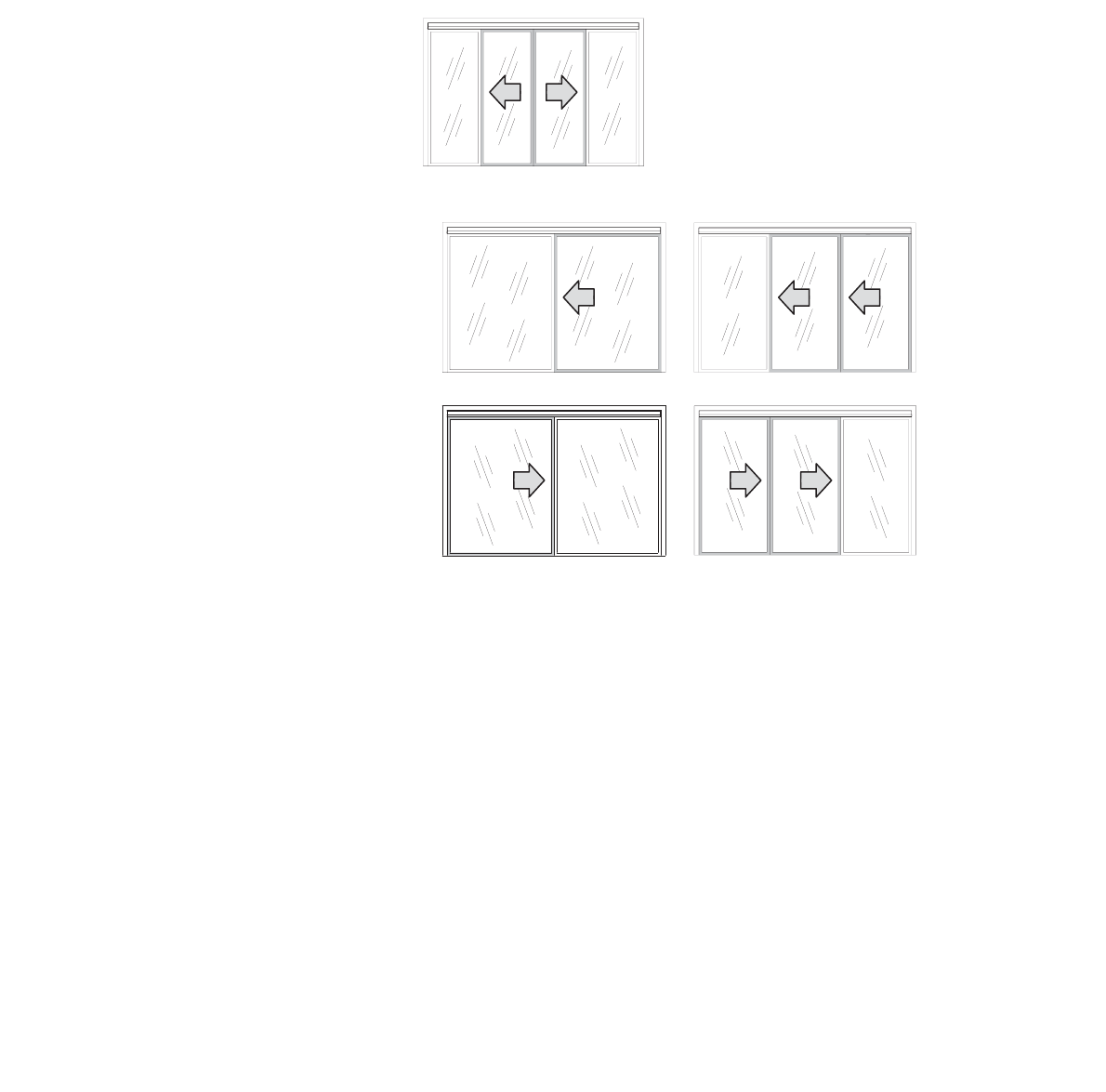
About the MultiDrive
The MultiDrive is an automatic door opening system dsigned for
residential and light-use commercial sliding doors.
Once installed, the MultiDrive mechanism is hidden discretely
behind an aluminum cover which blends in with the sliding door
coated to match the door and/or frame.
Figure 1: Bi-parting doors with the MultiDrive.
Figure 2: Non-bi-parting doors with the MultiDrive: a) single leftsliding
door, b) telescopic left-sliding door, c) single right-sliding door,
and d) telescopic right-sliding door.
Warnings
• Any manual lock on the sliding door should be removed or
deactivated, otherwise the MultiDrive and/or sliding door may
be damaged if activated while the lock is closed.
•
stores.
• The MultiDrive may be used in light commercial
environments. Speak with an authorized Autoslide Pty or
Autoslide LLC representative about your application prior to
purchase.
© 2018 Autoslide Pty Ltd MultiDrive <1>
© 2018 Autoslide Pty Ltd MultiDrive 6
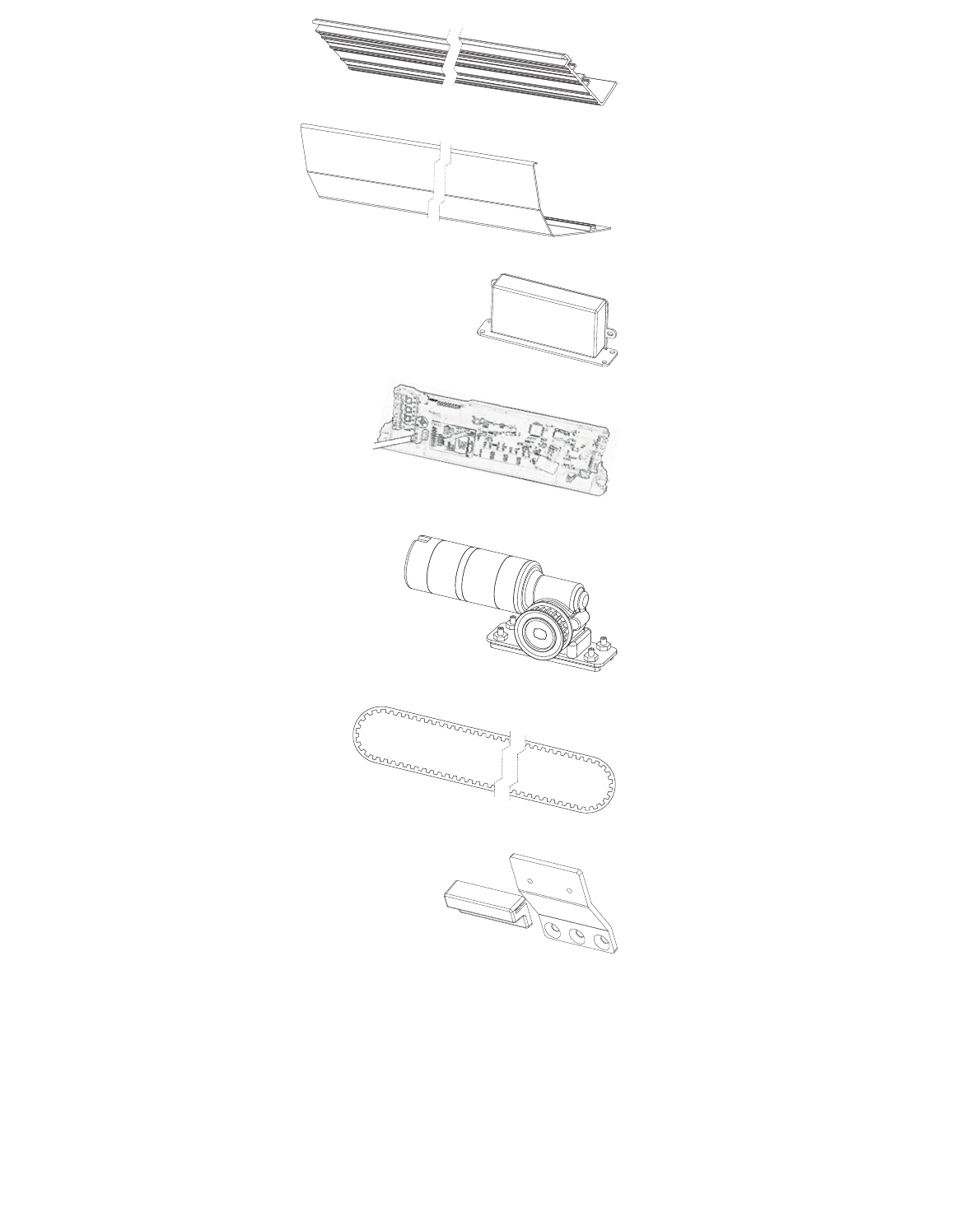
MultiDrive Standard Parts
Base x 1
Cover x 1
AC adapter x 1
Controller x 1
Motor x 1
Belt x 1
Top bracket x 1
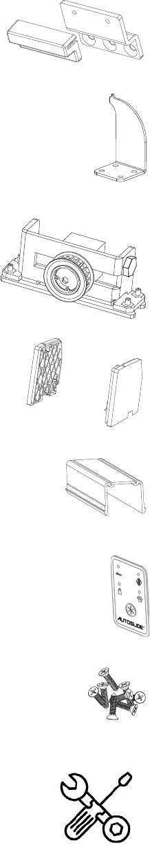
© 2018 Autoslide Pty Ltd MultiDrive 7
Bottom
bracket x 1
Cover clip x 2
Belt
tensioner x 1
End cap x 2
Cable cover x 3
Mode pad x1
Screws x 13
Tool Packet x1
© 2018 Autoslide Pty Ltd MultiDrive <1>
© 2018 Autoslide Pty Ltd MultiDrive 8
1
2
3.15”
(80 mm)
Door requirements
Sliding door friction
The MultiDrive should only be installed on a door that slides
smoothly. If the door system does not, it is recommended to have
the door system maintenance prior to the installation of the
MultiDrive System.
The sliding friction should be low enough that the door opens and
Use a digital scale with a hook to measure the force to open and
close the door. If the force is greater than 35 pound-force, speak
with an authorized Autoslide Pty representative on how to proceed.
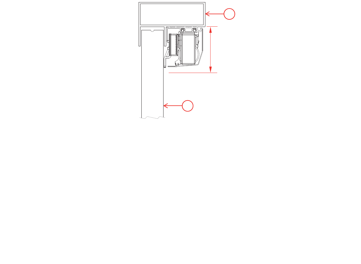
Space under the head jamb
The MultiDrive system sits directly below the head space of a
Figure 3.
situation arises.
Figure 3: Cross-section of a sliding door (1) with the MultiDrive below
the head jamb (2). The MultiDrive requires a 3.15-inch (80-mm)
clearance below the head jamb.

© 2018 Autoslide Pty Ltd MultiDrive <1>
© 2018 Autoslide Pty Ltd MultiDrive 9
Coating the cover
The MultiDrive includes a cover to conceal the motor and other
mechanisms.
The cover has an uncoated
cover match the sliding door, use a color sample from the door
and/or door trim to match the cover with the door system. The
painting of the cover should be powder coated for optimal durability
© 2018 Autoslide Pty Ltd MultiDrive <1>
W
L
© 2018 Autoslide Pty Ltd MultiDrive 10
Installation instructions
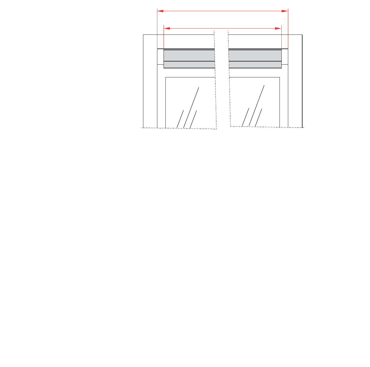
1. Cut parts to size
(a) Cut the cover to the correct length
Steps
Cut the cover to a length (L) which is 0.51” to 0.59”
shorter than the inside width (W) of the sliding door frame (see
Cut off any pins or clips used to hold the cover during the coating
process.
Figure 4: Cut the cover (shown in grey) to a length L which is 0.51” to
0.59” (13-15 mm) shorter than W.
(b) Cut the base to the same length
Cut the base to the same length L as the cover (0.51” to 0.59” or
13 to 15 mm shorter than W
© 2018 Autoslide Pty Ltd MultiDrive <1>
© 2018 Autoslide Pty Ltd MultiDrive 11
1
1
1
2. Attach Parts to the Base Prior to Mounting
The base holds the belt tensioner, motor, controller, AC adapter,
cover clips, Wi-Fi Module, and back up battery (optional
positions described below.
(a) Preparation
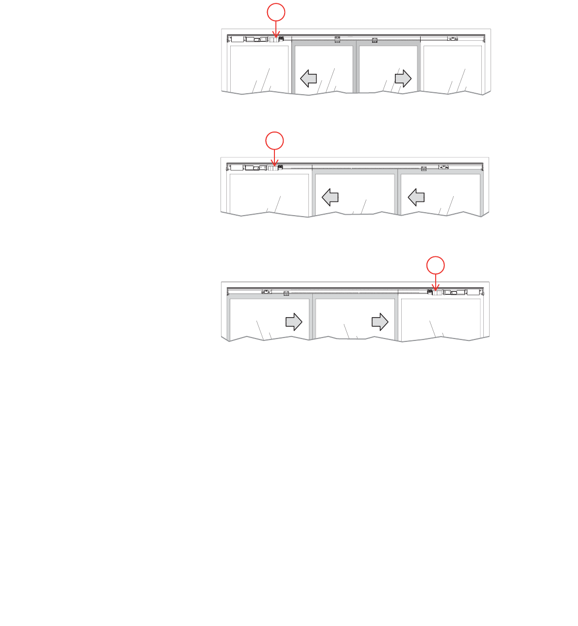
The layout of parts depends on whether the door is bi-parting, right
handed, or left handed.
Figure 5: Bi-parting doors: motor (1) is on the left.
Figure 6: Right handed door: motor (1) is on the left.
Figure 7: Left handed door: motor (1) is on the right.
Steps
1
Align the center of the base with the center of the door frame.
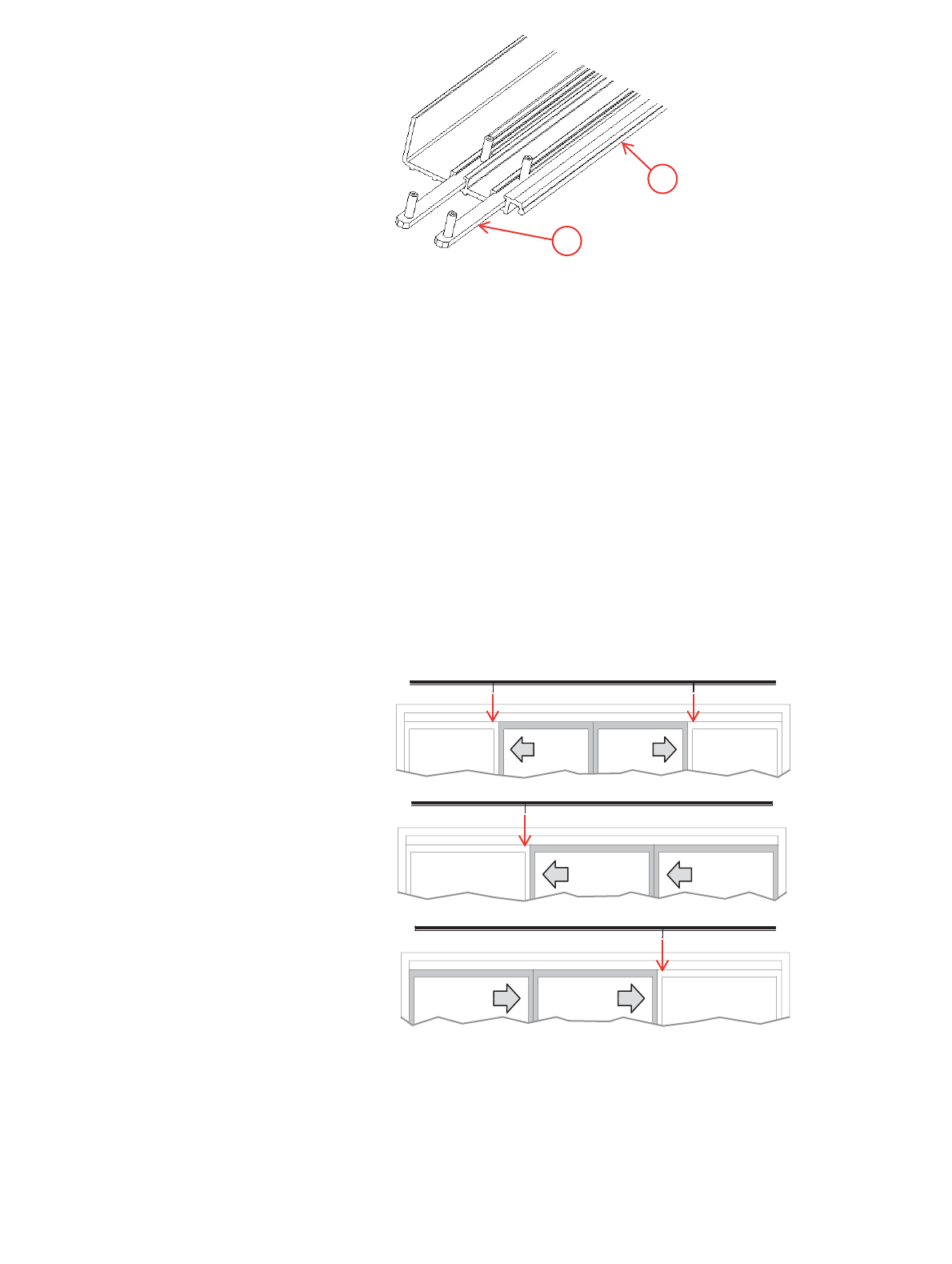
2. Each part attaches to the base with one or two “sliders”
Remove the
nuts from all sliders.
3. If you are installing optional wired sensors, lay the sensor
underneath the cover clips and motor.
© 2018 Autoslide Pty Ltd MultiDrive <1>
© 2018 Autoslide Pty Ltd MultiDrive 12
1
2
Figure 8: Sliders (1) in the two tracks on the base (2).
4. Use the following steps to set the position of each part on the
base.
(a) Cover clips
Guidelines for using cover clips
• Don’t use cover clips over the door opening because they will
be visible from the opposite side of some doors.
• Clips are not needed at the ends of the base because the end
caps support the cover there.
Steps
1. Use a cover clip behind the door frame of each
hides the clip from view on the other side of the door.
Slide each cover clip onto the base as in Figure 11. Make sure
points
towards the door.
door.
© 2018 Autoslide Pty Ltd MultiDrive <1>
© 2018 Autoslide Pty Ltd MultiDrive 13
A C
B
For
b
(c) Belt tensioner
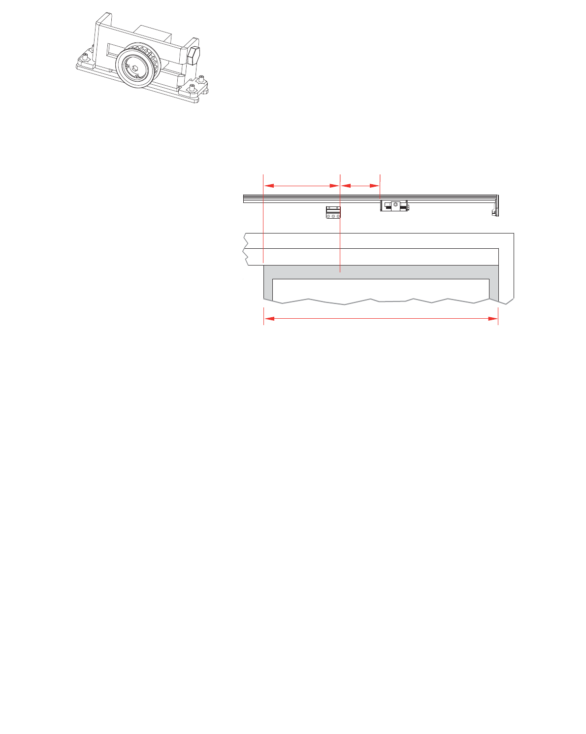
For bi-parting doors:
For bi-parting doors, the belt tensioner sits on the right side of the
1. Open the doors fully.
2. Slide the belt tensioner along the base until it is in front of the
left-hand door as shown in Figure 10, where:
A = 20-30% of the width B of that door
C =
3. Tighten the slider nuts to hold the belt tensioner in place.
4. Mark the position of the bottom bracket on both the base and
the door as in Figure 12.
Figure 10: Bi-parting doors: belt tensioner and bottom bracket.
The right side is shown with the right door open.
For right handed doors (non-bi-parting):
For left-opening doors, the belt tensioner sits on the right side of
1. Close the door fully.
2. Slide the belt tensioner along the base until it is in front of
closed sliding door as shown in Figure 11, where:
A = 20-30% of the width B of that door
C =
3. Tighten the slider nuts to hold the belt tensioner in place.
4. Mark the position of the bottom bracket on both the base and
the door as in Figure 11.
© 2018 Autoslide Pty Ltd MultiDrive <1>
(d) Motor
Fo
© 2018 Autoslide Pty Ltd MultiDrive 14
AC
B
A C
B
Figure 11: Left-opening sliding door: belt tensioner and bottom
bracket. The right side is shown with sliding door closed.
For left handed doors (non-bi-parting):
For right-opening doors, the belt tensioner sits on the left side of
1. Close the door fully.
2. Slide the belt tensioner along the base until it is in front of
closed sliding door as shown in Figure 12, where:
A = 20-30% of the width B of that door
C =
3. Tighten the slider nuts to hold the belt tensioner in place.
4. Mark the position of the bottom bracket on both the base and
the door as in Figure 14.
Figure 12: Right-opening sliding door: belt tensioner and bottom
bracket. The left side is shown with sliding door closed.
(d) Motor
The motor sits at the opposite end of the base to the belt tensioner.
For bi-parting doors:
1. Open the doors fully.
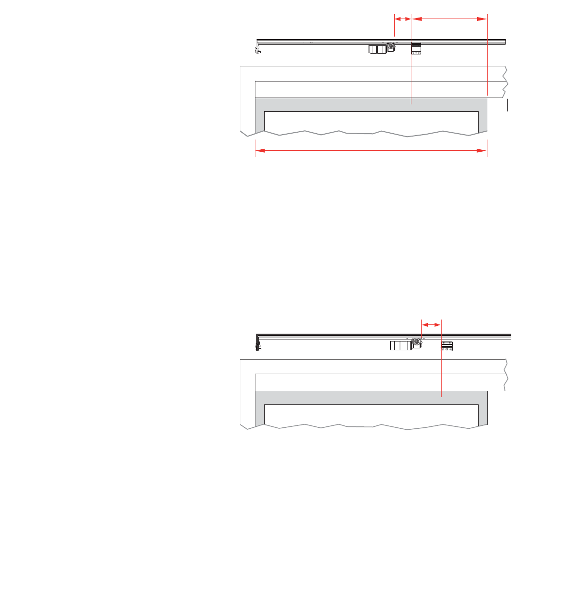
© 2018 Autoslide Pty Ltd MultiDrive <1>
© 2018 Autoslide Pty Ltd MultiDrive 15
C
B
A
C
2. Slide the motor along the base until it is in front of left-hand
sliding door as shown in Figure 15, where:
A = 20-30% of the width B of that door
C =
Note:
contact your MultiDrive supplier about obtaining a different
3. Tighten the slider nuts to hold the motor in place.
4. Mark the position of the top bracket on both the base and the
left-hand sliding door as in Figure 13.
Figure 13: Bi-parting doors: motor and top bracket. The left side
is shown with left door open.
For left-opening doors (non-bi-parting):
1. Open the door fully.
2. Slide the motor along the base until it is 2”
mark you made on the door for the bottom bracket position
(Figure 13 and Figure 14, where C =
3. Tighten the slider nuts to hold the motor in place.
Note: Non-bi-parting doors do not use a top bracket.
Figure 14: Left-opening sliding door with motor and bottom
bracket. The left side is shown with the sliding door open.
For right-opening doors (non-bi-parting):
1. Open the door fully.
© 2018 Autoslide Pty Ltd MultiDrive <1>
© 2018 Autoslide Pty Ltd MultiDrive 16
C
Step
2. Slide the motor along the base until it is 2”
mark you made on the door for the bottom bracket position
(Figure 14 and Figure 15, where C =
3. Tighten the slider nuts to hold the motor in place.
Note: Non-bi-parting doors do not use a top bracket.
Figure 15: Right-opening sliding door: motor and bottom
bracket. The right side is shown with the sliding door open.
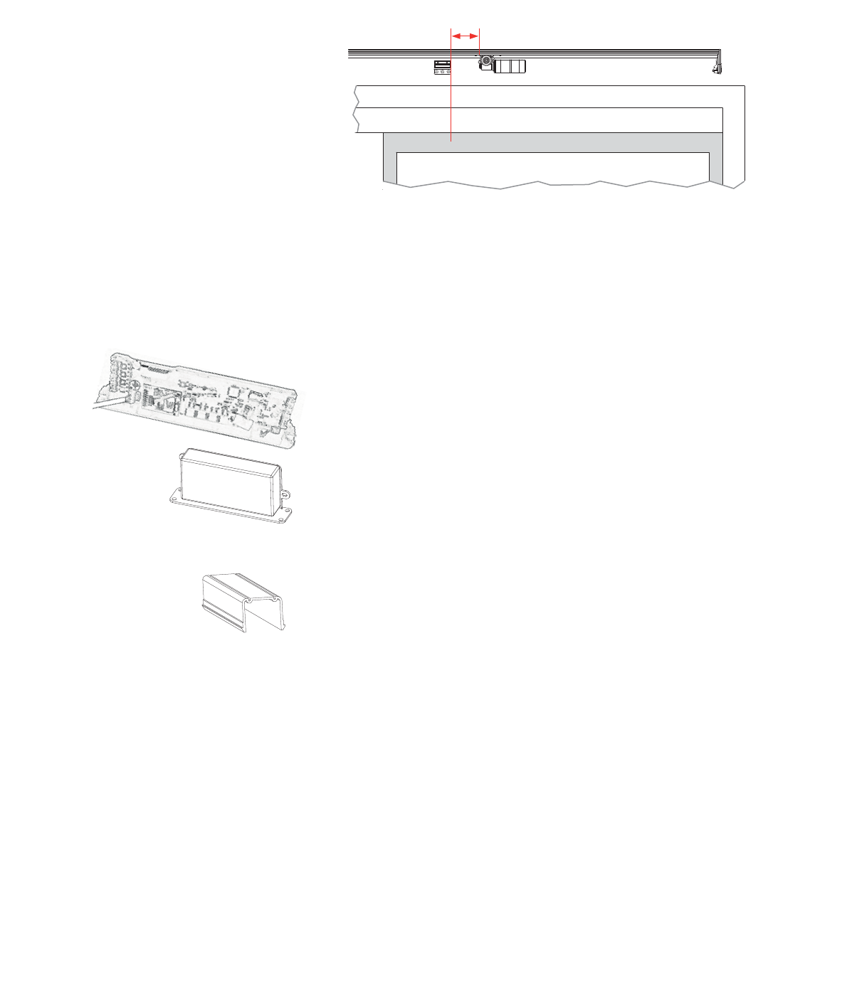
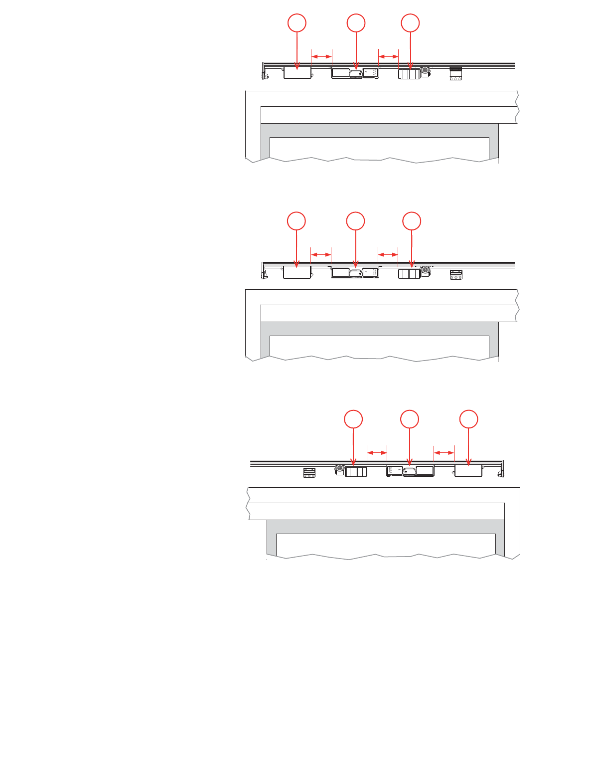
(e) Controller and AC adapter
The controller and AC adapter sit next to the motor.
Steps:
1. Lay the motor cable on the base in between the two tracks.
it is 2”
depending on the type of door, where D
slider should be in the track furthest from the door.
until it is 2”
where D =
furthest from the door.
4. If you are installing a mode pad on the door jam, lay the cable
connected to the mode pad on the base between the two
tracks and underneath the AC adapter.
on the base to prevent cables touching the belt.
© 2018 Autoslide Pty Ltd MultiDrive <1>
© 2018 Autoslide Pty Ltd MultiDrive 17
321
DD
3
21
DD
3 2 1
D D
Figure 16: Bi-parting doors: AC adapter (1), controller (2), and
motor (3).
Figure 17: Right-opening door: AC adapter (1), controller (2), and
motor (3).
6. Tighten the slider nuts to hold the AC adapter and controller in
place.
labeled Motor.
port labeled Power.
© 2018 Autoslide Pty Ltd MultiDrive 18
Figure 19: Plug the cables into the controller.
9.
the AC adapter and base.
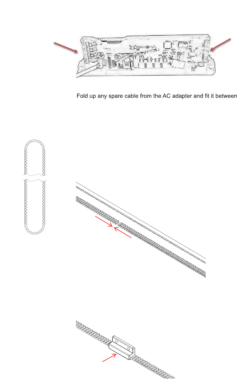
(f) Belt
Steps:
1. Take a length of belt and pass it around the motor pulley and
the belt tensioner pulley to form a loop.
One side of the loop will be closer to the base than the other
side. Keep the unconnected side furthest from the base.
2. Use your hands to gently pull the belt tight. Cut the belt so that
the two ends can touch without overlapping (Figure 20).
Figure 20: Cut the belt so that the two ends touch without
overlapping.
3. Keep two ends of the belt as close as possible to each other
and insert them into the bottom bracket (Figure 21).
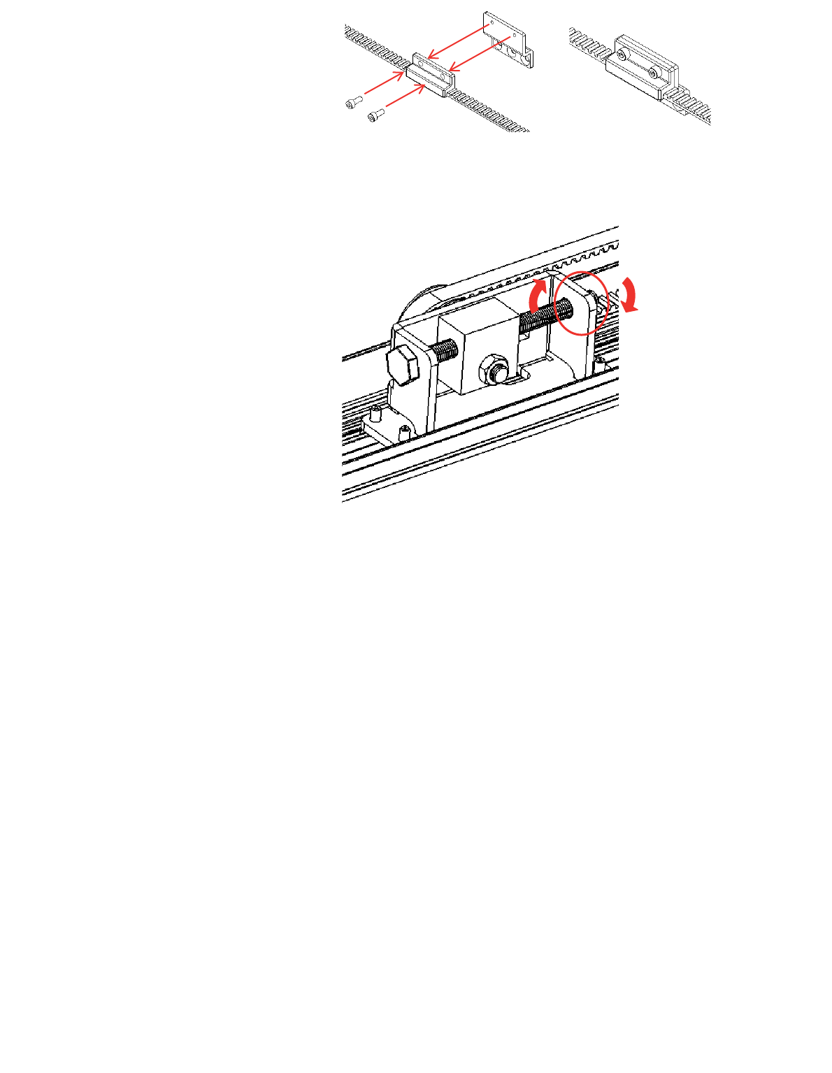
Figure 21: Insert the two ends of the belt into the bottom bracket.
4. Bolt together the two parts of the bottom bracket (Figure 22).
© 2018 Autoslide Pty Ltd MultiDrive <1>
© 2018 Autoslide Pty Ltd MultiDrive 19© 2018 Autoslide Pty Ltd MultiDrive 19
Figure 22: Bolt together the two parts of the bottom bracket.
5. On the belt tensioner, loosen the locking nut using the
Figure 23: Loosen the locking nut.
6. Turn the tensioning bolt clockwise
on the belt. Stop when the belt is pulled straight and does
not sag and is taut.
Do not over tighten the belt or the motor may get damaged.
Note: If the belt loosens when the tensioning bolt is turned
clockwise, then follow these steps:
1. Completely unscrew the tensioning bolt until it is
removed from the tensioning pulley.
2. Insert the tensioning bolt into the opposite end of the
tensioning pulley (where the locking nut was
3. Screw the locking nut back onto the tensioning bolt.
© 2018 Autoslide Pty Ltd MultiDrive <1>
© 2018 Autoslide Pty Ltd MultiDrive 20
Figure 24: Tighten the belt with the tensioning bolt.
Figure 25: Tighten the locking nut.
(g) End caps
Steps:
1. Each end cap has two sliders. If you are running wires out the
before inserting the endcaps onto the base.
2. To insert, loosen the nuts and push the sliders into the two
to gently tap the end caps into position.
3. Tighten the nuts on both sliders.
© 2018 Autoslide Pty Ltd MultiDrive 21
Figure 26:
3. Attach the base to the door
Steps:
Place the base against the head jamb and measure distance H
(Figure 27). His the distance between the base and the vertical
surface below the head jamb.
Figure 27: Place the base against the head jamb and measure H.
H
Secure AC cable on end cap and track
© 2018 Autoslide Pty Ltd MultiDrive <1>
© 2018 Autoslide Pty Ltd MultiDrive 22
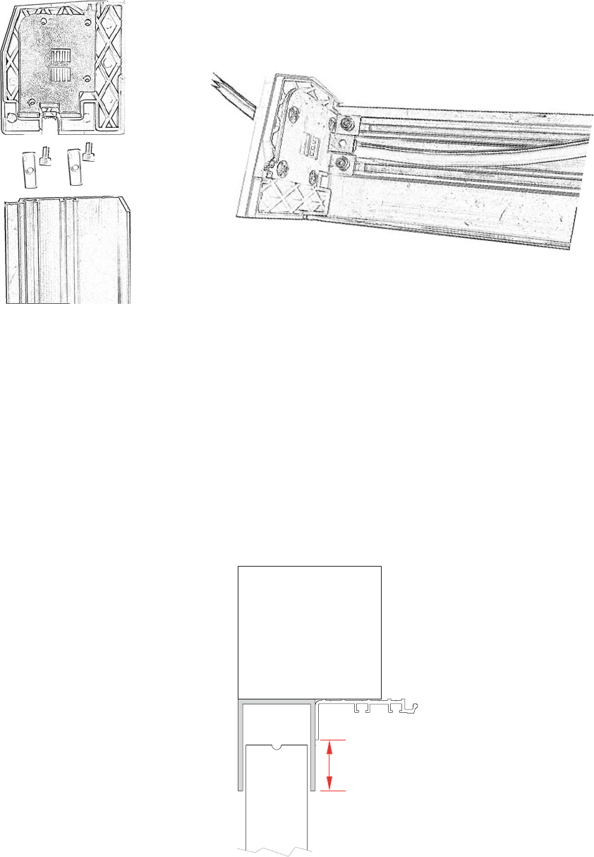
If H < 1” (25 mm):
If H
Otherwise, see the steps for H
Figure 28: If H < 0.99” (25 mm), screw the base to the head jamb.
seven places:
away, between the two tracks
tracks.
Figure 29: Screw positions in the base if H < 0.99” (25 mm).
2. Put the base into position under the head jamb. Leave a gap of
0.1” to 0.2”
vertical frames of the doors.
the base in position while doing this.
4. Use seven screws to hold the base in place for a 12’ length
Additional screws are needed for bases longer than 12’.
5. If the belt sags, increase the belt tension as described above.
© 2018 Autoslide Pty Ltd MultiDrive <1>
© 2018 Autoslide Pty Ltd MultiDrive 23
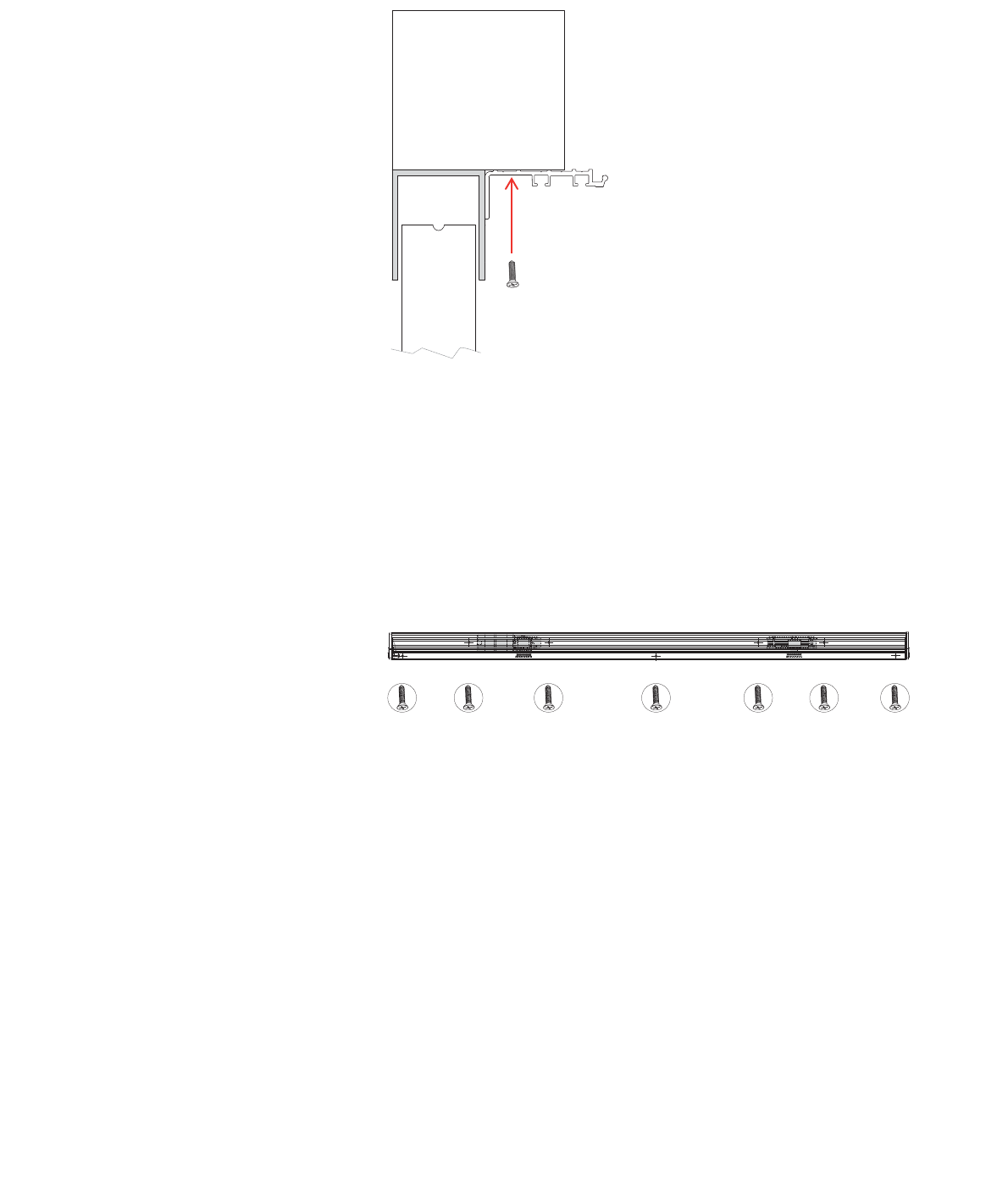
If H
If Hvertical surface
below the head jamb.
the base in seven places:
away
2. Put the base into position under the head jamb so that:
H is less
clear of the sliding doors.
5. If the belt sags, increase the belt tension as described above.
© 2018 Autoslide Pty Ltd MultiDrive <1>
© 2018 Autoslide Pty Ltd MultiDrive 24
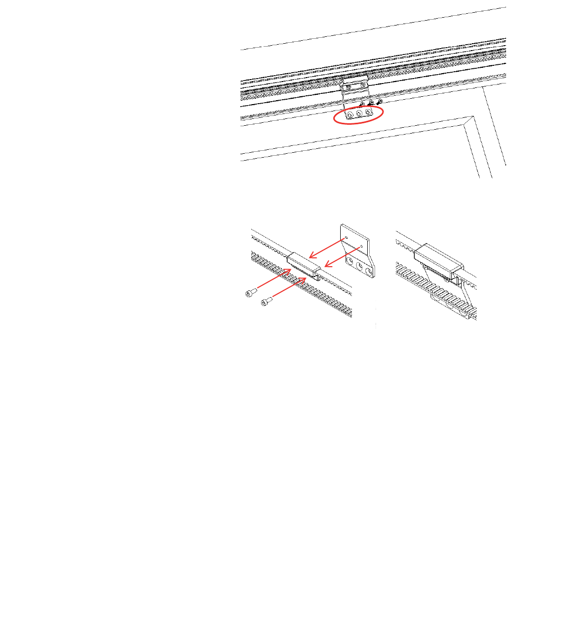
4. Attach the brackets and cover
(a) Bottom bracket
For bi-parting doors:
1. Open the doors fully.
2. Rotate the belt so that the bottom bracket reaches the
position you marked on the right-hand door earlier.
For non-bi-parting doors:
1. Close the door fully.
2. Rotate the belt so that the bottom bracket reaches the
position you marked on the sliding door earlier.
Then, for all door types:
3. Use the three holes in the bottom bracket to mark the
Note: Keep the holes above the glass in the sliding door to
avoid damaging the glass. If necessary, push the belt up to
0.1” to avoid the glass.
Figure 32: Drill three holes in the door for the bottom bracket. Be
sure the holes are above the door’s glass line to prevent damage
to the glass.
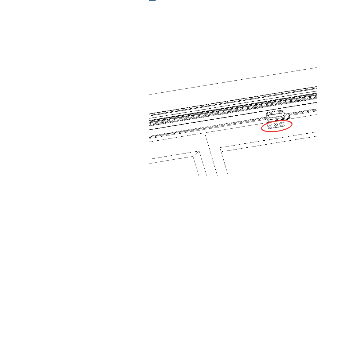
5. Hold the bottom bracket against the door. The bracket must
not bend the belt sideways. If space remains between the
bracket and the door, use included clear spacers or a shim to
obtain the extra thickness needed. The belt should run parallel
with the door.
6. Screw the bottom bracket along with shim/spacers to the door.
© 2018 Autoslide Pty Ltd MultiDrive <1>
© 2018 Autoslide Pty Ltd MultiDrive 25
(b) Top bracket (bi-parting doors only)
Steps:
1. Open both doors fully. Fit the top bracket onto the top loop of
door earlier.
2. Note:
contact your MultiDrive supplier about obtaining a different
Figure 33: The top bracket position.
Figure 34: Bolt the top bracket onto the top loop of the belt.
Note: Keep the holes above the glass in the sliding door to
avoid damaging the glass. If necessary, you can push the belt
up 0.1” to avoid the glass.
5. Hold the bottom bracket against the door. The bracket must
not bend the belt sideways. If space remains between the
bracket and the door, use included clear spacers or a shim to
obtain the extra thickness needed. The belt should run parallel
with the door.
6. Screw the bottom bracket along with shim/spacers to the door.
© 2018 Autoslide Pty Ltd MultiDrive <1>
© 2018 Autoslide Pty Ltd MultiDrive 26
(h) Cover
Clip the cover over the base to cover the MultiDrive mechanism
Note:
edge of the cover.
Figure 35: Clip the cover over the base.
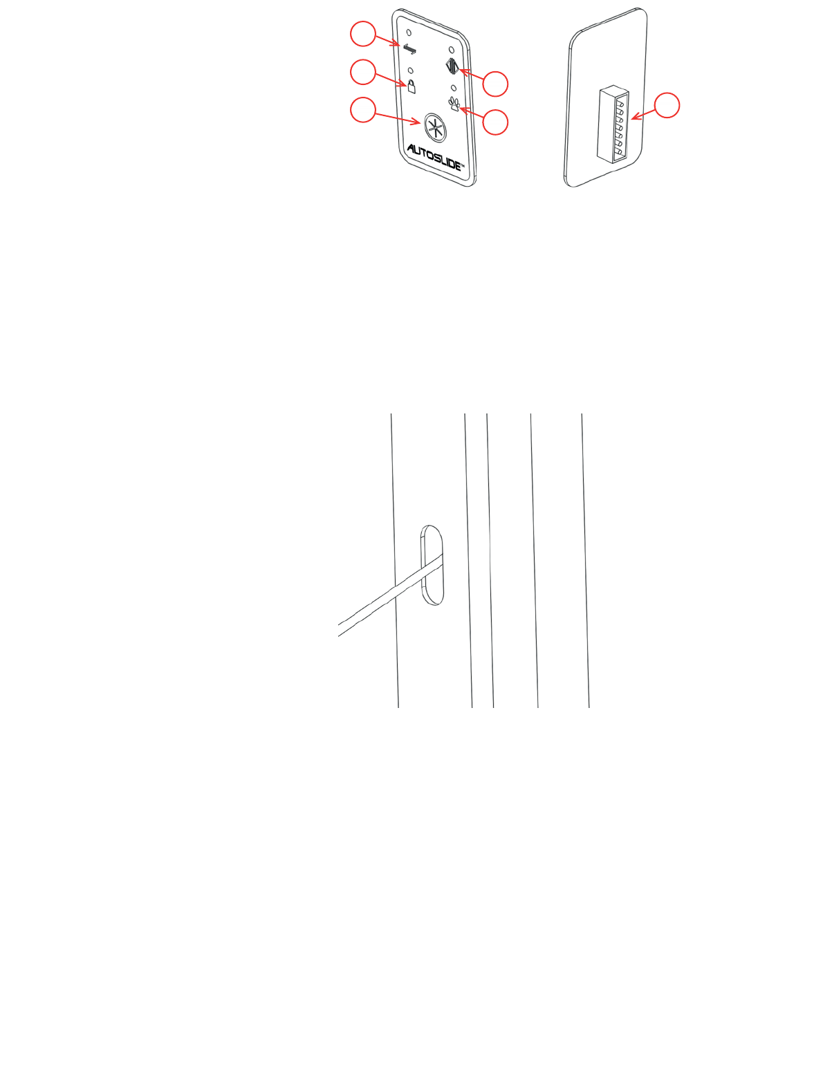
5. Install the mode pad
four modes displayed on the mode pad are:
• Unsecured Mode
locking function is disabled, & sensors for Indoor and Outdoor
work.
• Stack/Hold Open Mode
stays open until the mode is changed. In Stack Mode, the door
operates on a click-to-move setting. Push a button to open the
doors and then push a button to close the doors. Place DIP
switch #4 in the ‘On’ position to activate Stack Mode.
• Secured Mode
by a sensor or remote programmed for the Inside Sensor
setting. The automatic locking function is enabled.
• Pet Mode
programmed pet sensor. The door also opens to the normal
width when it is activated by a sensor or remote programmed
for the Inside Sensor setting. The automatic locking function is
T
© 2018 Autoslide Pty Ltd MultiDrive <1>
© 2018 Autoslide Pty Ltd MultiDrive 27
a) b)
3
2
4
15
6
Fi
mode pad with 7-pin connector.
Steps
1. Mark the position of the mode pad on a surface near the door.
2. Plug one end of the cable connected to the mode pad into the
port of the controller. The cable should pass underneath the
AC adapter. Feed the other end of the cable into the cavity
behind the door jamb.
3
the cable through the hole.
4. Peel backing paper from one side of the double-sided foam.
Press the sticky side of the foam onto the back of the mode
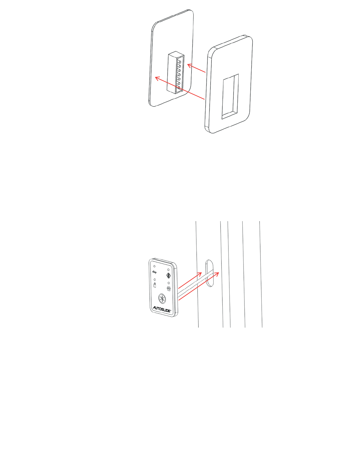
© 2018 Autoslide Pty Ltd MultiDrive <1>
© 2018 Autoslide Pty Ltd MultiDrive 28
Figure 38: Press the sticky side of the foam onto the back of the
mode pad.
5. Remove any dust, grease or moisture from the marked
position on the door jamb.
6. Peel the backing paper from the other side of the double-sided
7. If you are unable to feed the cable through the wall or jamb,
use cord cover or wire jamb to hide the cable.
Figure 39: Remove the backing paper, connect the cable and
press the sticky foam onto the door jam.
© 2018 Autoslide Pty Ltd MultiDrive <1>
© 2018 Autoslide Pty Ltd MultiDrive 29
3
54
21
Programming the controller
• Dial
when in auto mode and pet mode.
• DIP switches
controller
• Power Switch
• Sensor-Learn Button
calibrate input from wireless inputs such as motion sensors
• Red LED
motion sensor.
Figure 40: The controller.
1. Learn wireless inputs
These steps enable the MultiDrive to detect all wireless inputs,
such as motion sensors, remote controls and pet sensors.
1. Power up the controller:
Take the power cable for the AC adapter and plug it into a
general power outlet. Switch on the power at the outlet.
2
3. Activate all wireless inputs. For example, wave your hand in
front of each motion sensor and push the button on any remote
wireless inputs have been learnt by the controller.
If you wish to remove all learnt sensors and start again, press
released.

© 2018 Autoslide Pty Ltd MultiDrive <1>
© 2018 Autoslide Pty Ltd MultiDrive 30
2. Set DIP switches
#1 Distance Learn/Open Direction
programming of door width and direction by which the gear rotates.
rotate for a right-handed door. Flipping this dip switch away from you
Note: If your
system has been handed properly for the door it is being used on,
keep Dip Switch #1 in forward position (Off).
b. To program the door width, toggle this dip switch from current position, to
opposite position, and back to current position to send the system into
Learn Mode. The door will begin to open slowly. Let the door run to its
stop point or stop it yourself by applying reverse pressure on the door at
the position you want the door to open to for its maximum distance. Note:
This must be done while the power is turned ‘On.’
#2 Slam Shut
at the end. It is needed when the door is entering a tight jamb or a jamb with
Note: This setting cannot be used/turned ‘On’ when using system in Pet
Mode.
#3 Pet Distance Learn
distance for the Pet Mode. To program the pet distance, toggle this dip switch
open slowly. Stop the door by applying reverse pressure on the door at the
maximum position you want the door to open to for your pets.
#4 Stay Open/Stacker ModeBlue Mode will
and stay open when put in Blue Mode until the mode is changed to another mode.
Stack Mode when placed in Blue Mode. In Stack Mode, you can activate the
Blue Mode
#5 75% Power
This setting is good if you are using the system on a door with a light drag weight
#6 50% Power
#7
normal force the motor uses to operate the MultiDrive system.
#8 Beep Alert
Note: The decibel of the audible beep has not
been tested or approved by any lab to act as an approved alert device for
safety. It is only for general alert knowledge.

© 2018 Autoslide Pty Ltd MultiDrive <1>
© 2018 Autoslide Pty Ltd MultiDrive 31
3. Programming the Modes
Caution:
the door may start moving without warning.
Green Mode (Unsecured Mode)
The green light on the MultiDrive system indicates it is in the Unsecured Mode. This
means the MultiDrive will not lock your doors and allows for an auto-assist opening
when the door is manually opened. All sensors and devices programmed to the Inside
Sensor and Outside Sensor will activate your door.
system, or to create a smaller unsecured opening for a bi-parting door system.
To program, toggle Dip Switch #1 ‘On’ and then ‘Off’ to send the system into Learn
Mode. The door will then open slowly. Stop the door at the max open distance you
After the door completes two open and close cycles, the door will remain closed and
is now programmed.
Blue Mode (Stay Open & Stacker Modes)
The blue light on the MultiDrive system indicates it is either in the Stay Open Mode or
the Stacker Mode. This is determined by the position of Dip Switch #4.
If Dip Switch #4 is in the ‘Off’ position, the mode will act as Stay Open Mode. When
system is changed out of Blue Mode.
If Dip Switch #4 is in the ‘On’ position, the mode will act as Stacker Mode. This mode
is designed to allow the MultiDrive system to open multiple panels (telescoping and biparting
Blue Mode. The doors
can also be stopped and restarted at any time during travel in the Blue Mode as well.
To program, toggle Dip Switch #1 ‘On’ and then ‘Off’ to send the system into Learn
Mode. The door will then open slowly. Stop the door at the max open distance you
After the door completes two open and close cycles, the door will remain closed and
is now programmed. Note: The distance for each mode in the MultiDrive system
must be programmed individually.
The iLock feature is enabled in this mode providing a secure and locked door system
when the doors are fully closed. All devices programmed to the Outside Sensor
Setting will not work in this mode.
Red Mode (Secured Mode)
The red light on the MultiDrive system indicates it is in the Secure Mode. The iLock
feature is enabled in this mode providing a secure and locked door system when the
doors are fully closed. All devices programmed to the Outside Sensor Setting will not
work in this mode. The auto-assist function is disabled in the Red Mode.
system, or to create a smaller secure opening for a bi-parting door system.
To program, toggle Dip Switch #1 ‘On’ and then ‘Off’ to send the system into Learn
© 2018 Autoslide Pty Ltd MultiDrive 32
Mode. The door will then open slowly. Stop the door at the max open distance you
desire. The system will automatically finish its distance programming from this point.
After the door completes two open and close cycles, the door will remain closed and
is now programmed. Note: The distance for each mode in the MultiDrive system
must be programmed individually.
Orange Mode (Pet Mode)
The orange light on the MultiDrive system indicates it is in the Pet Mode. The iLock
feature is enabled in this mode providing a secure and locked door system when the
doors are fully closed. All devices programmed to the Outside Sensor Setting will not
work in this mode. The auto-assist function is disabled in the Orange Mode.
The Pet Mode will allow your pets to use any device programmed to the Pet Sensor
Setting to activate the door. Note: Devices programmed to the Pet Sensor Setting
cannot be used in Green, Blue, or Red Modes.
This mode is used for a single door system, the first panel of a telescoping door
system, or to create a pet opening for a bi-parting door system. When the door opens
in Pet Mode, the door will lock at its open position. This will help prevent the door from
being forced open by a possible int
Copyright
All content included on this manual (including, but not limited to, logos, images, photos,
designs, graphics and text) is the property of AUTOSLIDE PTY LTD and as such is
protected by AUSTRALIA and international copyright and other intellectual property laws.
Any unauthorised reproduction or copying of the products or images featured on this
manual and belonging to AUTOSLIDE PTY LTD may result in legal action.
Copyright©Dec 2010, AUTOSLIDE PTY LTD, All rights reserved
uder. Note: This mode cannot be used if Slam
Shut (Dip Switch #2) is activated.
To program the pet distance, toggle Dip Switch #3 ‘On’ and then ‘Off’ to send the
system into Learn Mode. The door will then open slowly. Stop the door at the max
open distance you desire for your pet. The system will automatically finish its distance
programming from this point. After the door closes, the door will remain closed and is
now programmed for your pet. Note: The distance for each mode in the MultiDrive
system must be programmed individually.
FCC Warning
This device complies with part 15 of the FCC Rules. Operation is subject to the
following two conditions: (1) This device may not cause harmful interference, and (2)
this device must accept any interference received, including interference that may
cause undesired operation.
Any Changes or modifications not expressly approved by the party responsible for
compliance could void the user's authority to operate the equipment.
Note: This equipment has been tested and found to comply with the limits for a
Class B digital device, pursuant to part 15 of the FCC Rules. These limits are
designed to provide reasonable protection against harmful interference in a
residential installation. This equipment generates, uses and can radiate radio
frequency energy and, if not installed and used in accordance with the instructions,
may cause harmful interference to radio communications. However, there is no
guarantee that interference will not occur in a particular installation. If this
equipment does cause harmful interference to radio or television reception, which
can be determined by turning the equipment off and on, the user is encouraged to
try to correct the interference by one or more of the following measures:
—Reorient or relocate the receiving antenna.
—Increase the separation between the equipment and receiver.
—Connect the equipment into an outlet on a circuit different from that to which the
receiver is connected.
—Consult the dealer or an experienced radio/TV technician for help.