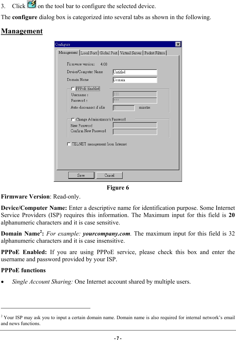
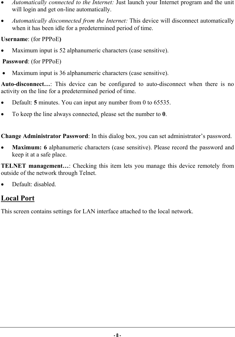
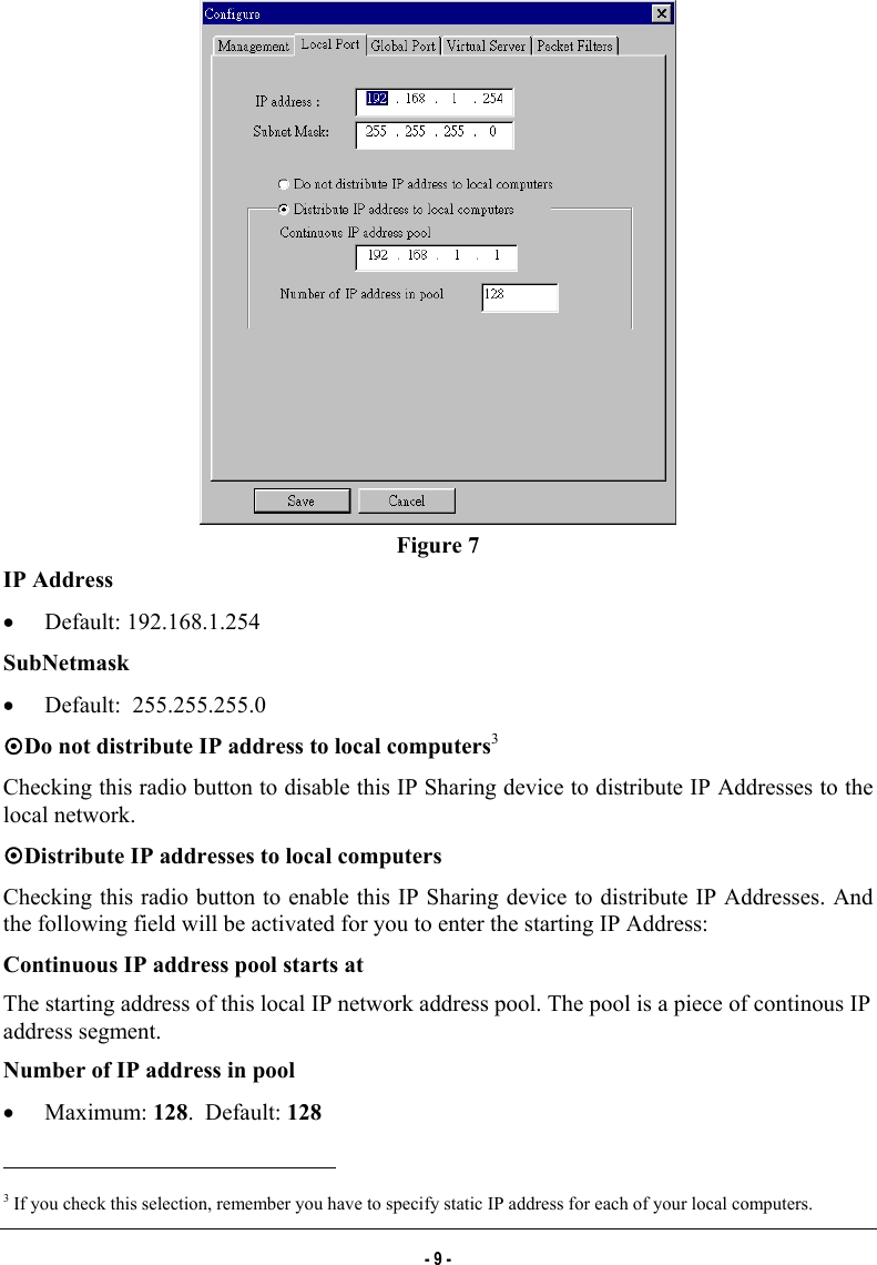
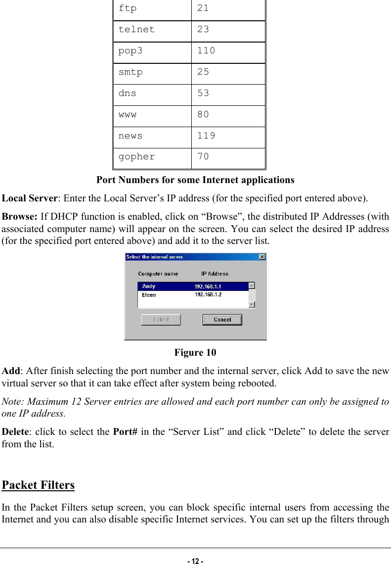
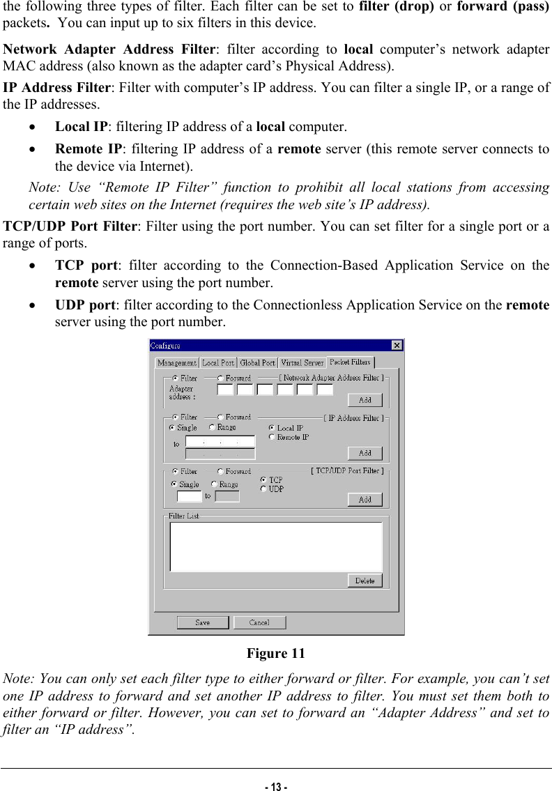
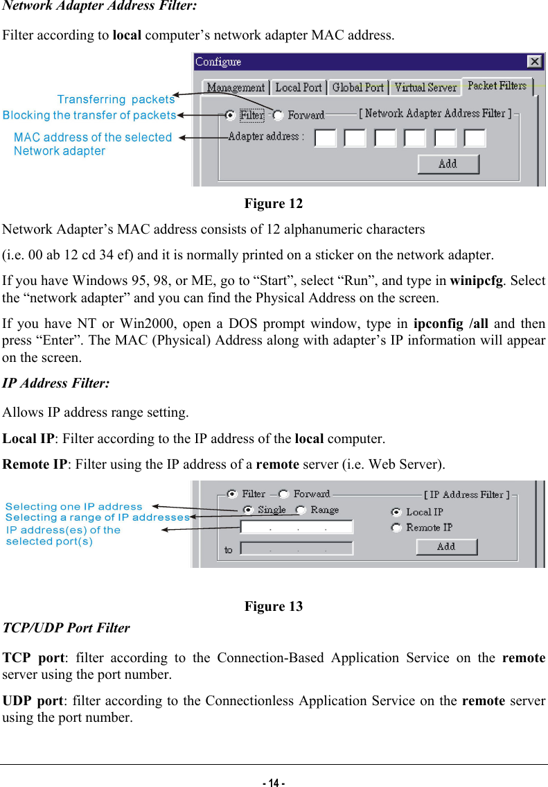
Abocom Systems CAS1040 IP Sharing Fast EtherSwitch For Cable/ xDSL Modem User Manual INTRODUCTION

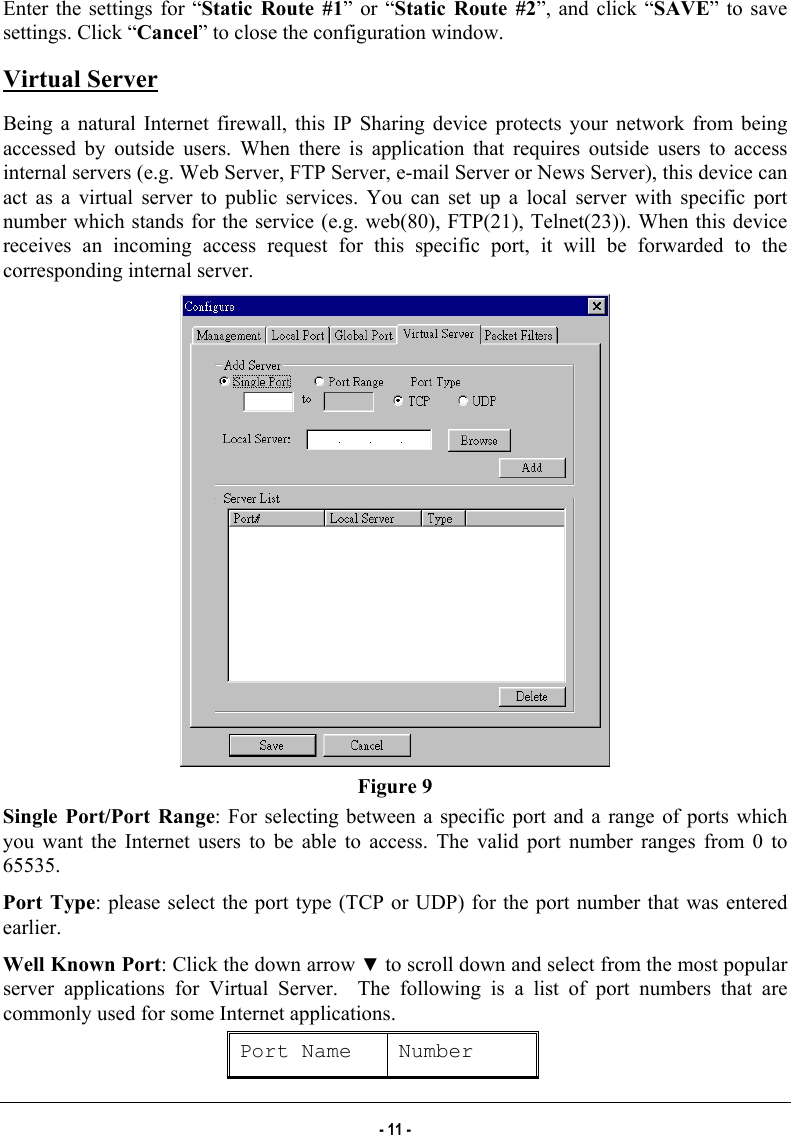
Abocom Systems Inc IP Sharing Fast EtherSwitch For Cable/ xDSL Modem INTRODUCTION

users manual 2

 3. Click   on the tool bar to configure the selected device. The configure dialog box is categorized into several tabs as shown in the following. Management  Figure 6 Firmware Version: Read-only.  Device/Computer Name: Enter a descriptive name for identification purpose. Some Internet Service Providers (ISP) requires this information. The Maximum input for this field is 20 alphanumeric characters and it is case sensitive. Domain Name2:  For example: yourcompany.com. The maximum input for this field is 32 alphanumeric characters and it is case insensitive. PPPoE Enabled: If you are using PPPoE service, please check this box and enter the username and password provided by your ISP.  PPPoE functions •  Single Account Sharing: One Internet account shared by multiple users.                                                            2 Your ISP may ask you to input a certain domain name. Domain name is also required for internal network’s email and news functions. - 7 -
 •  Automatically connected to the Internet: Just launch your Internet program and the unit will login and get on-line automatically.   •  Automatically disconnected from the Internet: This device will disconnect automatically when it has been idle for a predetermined period of time. Username: (for PPPoE) •  Maximum input is 52 alphanumeric characters (case sensitive). Password: (for PPPoE) •  Maximum input is 36 alphanumeric characters (case sensitive). Auto-disconnect…: This device can be configured to auto-disconnect when there is no activity on the line for a predetermined period of time. •  Default: 5 minutes. You can input any number from 0 to 65535. •  To keep the line always connected, please set the number to 0.  Change Administrator Password: In this dialog box, you can set administrator’s password.  •  Maximum: 6 alphanumeric characters (case sensitive). Please record the password and keep it at a safe place. TELNET management…: Checking this item lets you manage this device remotely from outside of the network through Telnet.  •  Default: disabled. Local Port This screen contains settings for LAN interface attached to the local network. - 8 -
  Figure 7 IP Address •  Default: 192.168.1.254 SubNetmask •  Default:  255.255.255.0 ~Do not distribute IP address to local computers3 Checking this radio button to disable this IP Sharing device to distribute IP Addresses to the local network. ~Distribute IP addresses to local computers Checking this radio button to enable this IP Sharing device to distribute IP Addresses. And the following field will be activated for you to enter the starting IP Address:  Continuous IP address pool starts at The starting address of this local IP network address pool. The pool is a piece of continous IP address segment. Number of IP address in pool •  Maximum: 128.  Default: 128                                                            3 If you check this selection, remember you have to specify static IP address for each of your local computers. - 9 -
  Global Port This screen contains settings for the Global interface. Different WAN interface, i.e. ADSL with PPPoE enabled, ADSL/Cable modem, or Leased Line will have different display as illustrated below             PPPoE enabled                                  Leased line with an fixed IP address    ADSL/Cable with DHCP IP address Figure 8 Adapter Address:  It is necessary for some ISP to identify this device by its MAC address.  Obtain global port configuration automatically:  If this selection was grayed out, it means you are using ADSL PPPoE (To be set in the Management part. See the previous section). The Global port IP address is then obtained through DHCP protocol from ISP after the device boots up.  The address may vary each time the device restarts. If not, then you can choose to obtain a dynamic IP address, or static IP address.  Set static global port configuration: Check this item if your ISP provides you with a fixed IP address.  IP address: Provided by your ISP. SubNetmask4: Provided by your ISP.  Gateway/DNS server #1/DNS server #2: These values will be automatically provided once you click “Obtain global port configuration automatically”. You can change the values if necessary. Static Route: You can set static routes to manually administrate the network topology/traffic when the dynamic route is not effective enough.                                                             4 If you checked PPPoE in Management tab (see the Management section), “Obtain global port configuration automatically” and “Set static global port configuration” are grayed to deny any modification. - 10 -
 Enter the settings for “Static Route #1” or “Static Route #2”, and click “SAVE” to save settings. Click “Cancel” to close the configuration window. Virtual Server Being a natural Internet firewall, this IP Sharing device protects your network from being accessed by outside users. When there is application that requires outside users to access internal servers (e.g. Web Server, FTP Server, e-mail Server or News Server), this device can act as a virtual server to public services. You can set up a local server with specific port number which stands for the service (e.g. web(80), FTP(21), Telnet(23)). When this device receives an incoming access request for this specific port, it will be forwarded to the corresponding internal server.  Figure 9 Single Port/Port Range: For selecting between a specific port and a range of ports which you want the Internet users to be able to access. The valid port number ranges from 0 to 65535. Port Type: please select the port type (TCP or UDP) for the port number that was entered earlier. Well Known Port: Click the down arrow ▼ to scroll down and select from the most popular server applications for Virtual Server.  The following is a list of port numbers that are commonly used for some Internet applications.  Port Name  Number - 11 -
 ftp 21 telnet 23 pop3 110 smtp 25 dns 53 www 80 news 119 gopher 70 Port Numbers for some Internet applications Local Server: Enter the Local Server’s IP address (for the specified port entered above). Browse: If DHCP function is enabled, click on “Browse”, the distributed IP Addresses (with associated computer name) will appear on the screen. You can select the desired IP address (for the specified port entered above) and add it to the server list.  Figure 10 Add: After finish selecting the port number and the internal server, click Add to save the new virtual server so that it can take effect after system being rebooted.  Note: Maximum 12 Server entries are allowed and each port number can only be assigned to one IP address. Delete: click to select the Port# in the “Server List” and click “Delete” to delete the server from the list.  Packet Filters In the Packet Filters setup screen, you can block specific internal users from accessing the Internet and you can also disable specific Internet services. You can set up the filters through - 12 -
 the following three types of filter. Each filter can be set to filter (drop)  or forward (pass) packets.  You can input up to six filters in this device. Network Adapter Address Filter: filter according to local computer’s network adapter MAC address (also known as the adapter card’s Physical Address). IP Address Filter: Filter with computer’s IP address. You can filter a single IP, or a range of the IP addresses. •  Local IP: filtering IP address of a local computer. •  Remote IP: filtering IP address of a remote server (this remote server connects to the device via Internet). Note: Use “Remote IP Filter” function to prohibit all local stations from accessing certain web sites on the Internet (requires the web site’s IP address). TCP/UDP Port Filter: Filter using the port number. You can set filter for a single port or a range of ports. •  TCP port: filter according to the Connection-Based Application Service on the remote server using the port number. •  UDP port: filter according to the Connectionless Application Service on the remote server using the port number.  Figure 11 Note: You can only set each filter type to either forward or filter. For example, you can’t set one IP address to forward and set another IP address to filter. You must set them both to either forward or filter. However, you can set to forward an “Adapter Address” and set to filter an “IP address”. - 13 -
 Network Adapter Address Filter: Filter according to local computer’s network adapter MAC address.  Figure 12 Network Adapter’s MAC address consists of 12 alphanumeric characters (i.e. 00 ab 12 cd 34 ef) and it is normally printed on a sticker on the network adapter. If you have Windows 95, 98, or ME, go to “Start”, select “Run”, and type in winipcfg. Select the “network adapter” and you can find the Physical Address on the screen. If you have NT or Win2000, open a DOS prompt window, type in ipconfig /all and then press “Enter”. The MAC (Physical) Address along with adapter’s IP information will appear on the screen. IP Address Filter: Allows IP address range setting. Local IP: Filter according to the IP address of the local computer. Remote IP: Filter using the IP address of a remote server (i.e. Web Server).   Figure 13 TCP/UDP Port Filter TCP port: filter according to the Connection-Based Application Service on the remote server using the port number. UDP port: filter according to the Connectionless Application Service on the remote server using the port number. - 14 -
  Figure 14 When you have finished setting the filters, click Add and the added filter will appear on the Filter List. To remove a filter, click to select the filter in the Filter List and click Delete.  After the configuration, click on Save to save the settings. Click Cancel to cancel the configuration process.  Figure 15 Please see examples on how to setup filters in Terminal Command section under vserv. - 15 -
 CONFIGURATION VIA WEB   Assuming the workstation’s TCP/IP is set to obtain IP automatically and the IP Sharing Device’s Local Port is set to “Distribute IP” (default), and all the cables are connected correctly. Open the browser, enter the local port IP address (default at 192.168.1.254) of the IP Sharing Device, and click “Go” to get the login page.   No user name or password is required for the first time login, click OK to continue when the following dialog box appears.   At the setup home page, the left navigation pane where bookmarks are provided, links you directly to the desired setup page. You can select Management, Local Port, Global Port, Virtual Server, Packet Filter, Advanced Settings or Network Status. Click on the desired setup page to expand the page in the main navigation pane. The setup pages covered in this utility are described below.  Management Change Administrator’s Password: Check and type in “new password”, and then at “confirm password”, retype the new password to set/change the administrator’s password.  •  Maximum: 6 alphanumeric characters (case sensitive). - 16 -

Navigation menu