Abocom Systems WAP5502 802.11b/g/n Compact Wireless Router User Manual
Abocom Systems Inc 802.11b/g/n Compact Wireless Router
UserManual.wiki
>
Abocom Systems
>
WAP5502 User Manual
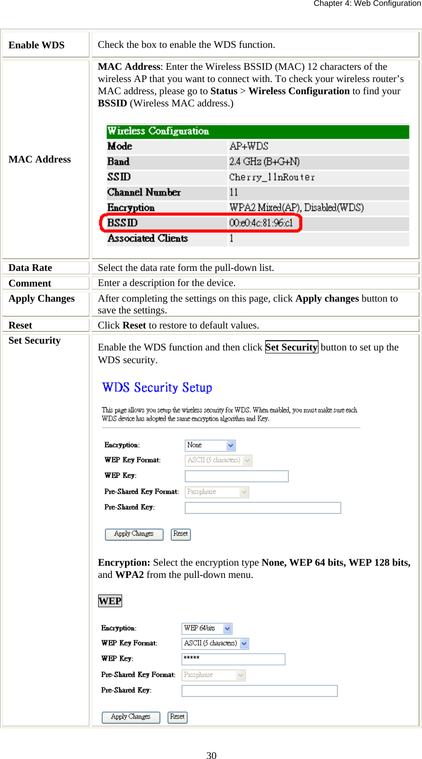
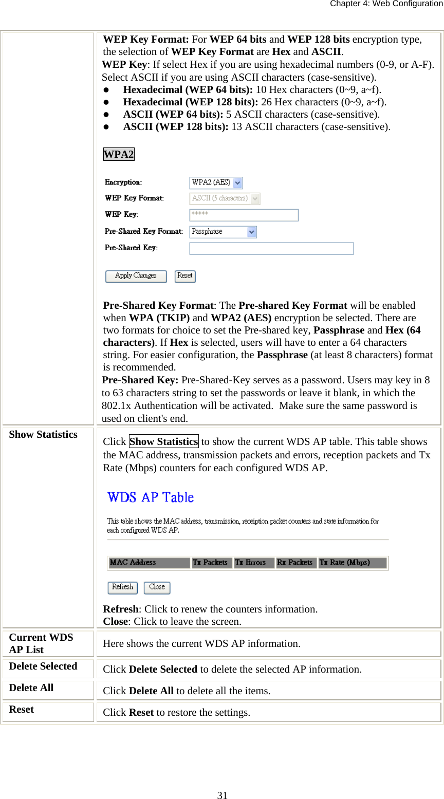
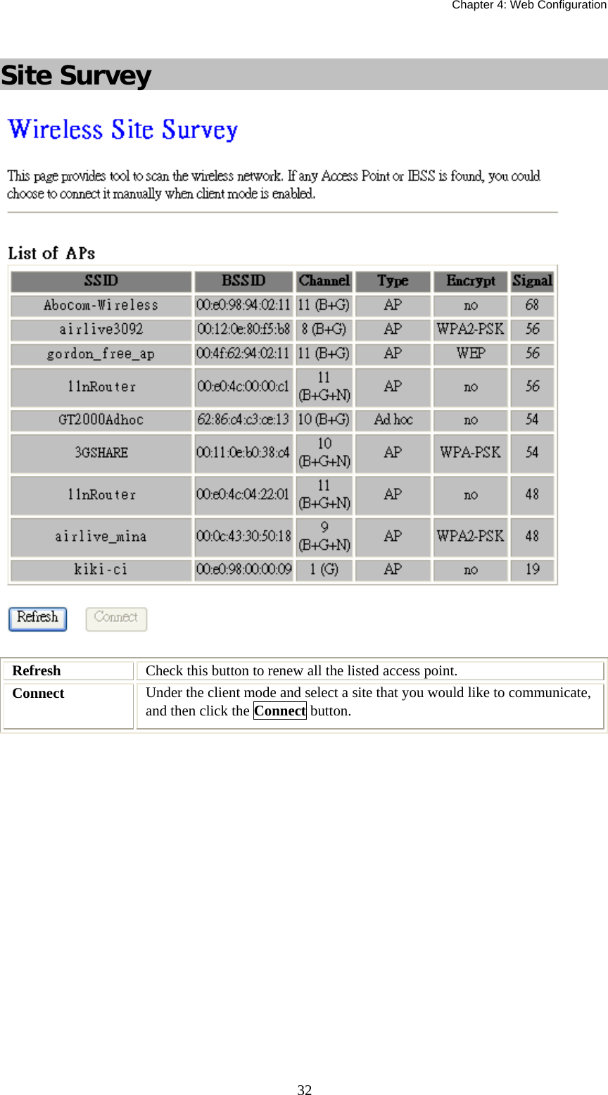
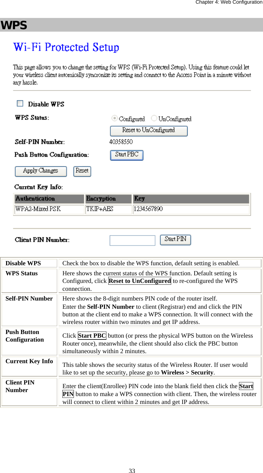
User Manual
Navigation menu
Upload a User Manual
Namespaces
Wiki Guide
HTML
PDF
Info
Views
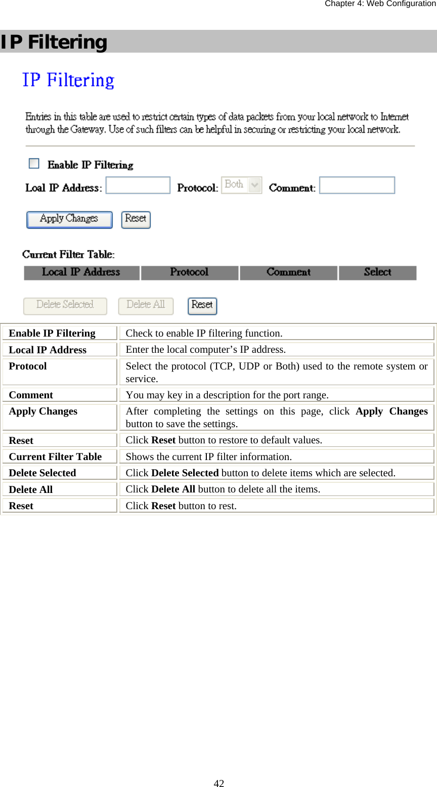
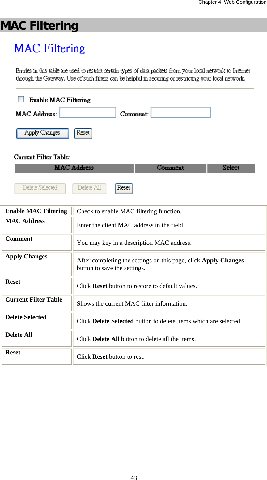
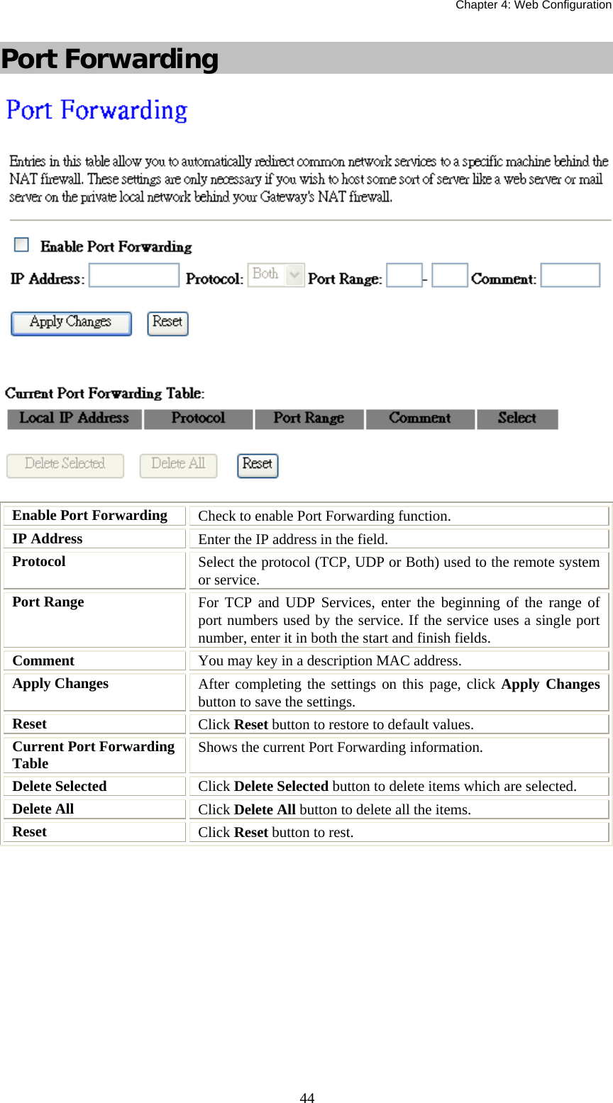
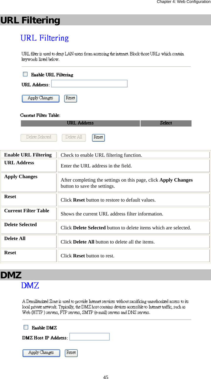
User Manual
Discussion / Help
Navigation