Abocom Systems WAP5502 802.11b/g/n Compact Wireless Router User Manual
Abocom Systems Inc 802.11b/g/n Compact Wireless Router
User Manual

Abocom
802.11b/g/n Compact
Wireless Router
model name :
WAP5502
User’s Manual

Federal Communication Commission
Interference Statement
This equipment has been tested and found to comply with the limits for a Class B digital device,
pursuant to Part 15 of the FCC Rules. These limits are designed to provide reasonable protection
against harmful interference in a residential installation. This equipment generates uses and can
radiate radio frequency energy and, if not installed and used in accordance with the instructions,
may cause harmful interference to radio communications.
However, there is no guarantee that interference will not occur in a particular installation. If this
equipment does cause harmful interference to radio or television reception, which can be
determined by turning the equipment off and on, the user is encouraged to try to correct the
interference by one or more of the following measures:
Reorient or relocate the receiving antenna.
Increase the separation between the equipment and receiver.
Connect the equipment into an outlet on a circuit different from that to which the receiver is
needed.
Consult the dealer or an experienced radio/TV technician for help.
Warning: Changes or modifications to this unit not expressly approved by the party responsible
for compliance could void the user authority to operate the equipment.
This device complies with Part 15 of the FCC Rules. Operation is subject to the following two
conditions: (1) this device may not cause harmful interference, and (2) this device must accept any
interference received, including interference that may cause undesired operation.
The user’s manual or instruction manual for an intentional or unintentional radiator shall caution the
user that changes or modifications not expressly approved by the party responsible for compliance
could void the user’s authority to operate the equipment.
For product available in the USA/Canada market, only channel 1~11 can be operated. Selection of
other channels is not possible.
CAUTION:
1. To comply with FCC RF exposure compliance requirements, a separation distance of at least 20 cm
must be maintained between the antenna of this device and all persons.
2. This Transmitter must not be co-located or operating in conjunction with any other antenna or
transmitter

2
Table of Content
Chapter 1: Introduction 1
Features 1
Hardware Connection 1
LED Indicators 2
Chapter 2: About the Operation Modes 3
AP Mode 3
GW Mode 3
Client Mode (Infrastructure) 4
Chapter 3: Configuration 5
Login 5
Common Connection Types 6
Configuration via Web 7
Operation Mode 7
Status 23
System Data 23
TCP/IP 24
Other 25
Chapter 4: PC Configuration 28
Overview 28
Windows Clients 28
TCP/IP Settings - Overview 28
Checking TCP/IP Settings - Windows 2000 29
Checking TCP/IP Settings - Windows XP 30
Internet Access 32
Macintosh Clients 33
Linux Clients 33
Other Unix Systems 33
Wireless Station Configuration 34
Appendix A Troubleshooting 35
Overview 35
General Problems 35
Internet Access 35
Wireless Access 36
Appendix B About Wireless LANs 37
BSS 37
Channels 37
WEP 37
Wireless LAN Configuration 37
Regulatory Approvals 38
CHAPTER 1: INTRODUCTION..............................................................................2
Features.........................................................................................................................................2
Physical Details...........................................................................................................................3
CHAPTER 2: OPERATION MODES......................................................................6
Router Mode ................................................................................................................................6
Access Point Mode.....................................................................................................................7
Client Mode ..................................................................................................................................7
CHAPTER 3: INSTALLATION................................................................................9
Hardware Connection...............................................................................................................9
Login.............................................................................................................................................11

2
CHAPTER 4: WEB CONFIGURATION...............................................................17
Setup Wizard.............................................................................................................................17
Wireless.......................................................................................................................................21
TCP/IP Settings........................................................................................................................35
Firewall........................................................................................................................................41
QoS................................................................................................................................................47
Route Setup ...............................................................................................................................48
Management..............................................................................................................................49
Log out.........................................................................................................................................57
CHAPTER 5: PC CONFIGURATION...................................................................58
Overview.....................................................................................................................................58
Windows Clients.......................................................................................................................58
Macintosh Clients.....................................................................................................................66
Linux Clients..............................................................................................................................66
Other Unix Systems.................................................................................................................67
Wireless Station Configuration...........................................................................................67
APPENDIX A: TROUBLESHOOTING.................................................................68
Overview.....................................................................................................................................68
General Problems.....................................................................................................................68
Internet Access.........................................................................................................................68
Wireless Access ........................................................................................................................69
APPENDIX B: ABOUT WIRELESS LANS..........................................................71
BSS................................................................................................................................................71
Channels......................................................................................................................................72
Security........................................................................................................................................72
Wireless LAN Configuration.................................................................................................73
Chapter 1:
Introduction
This is a pocket size IEEE802.11b/g/n router with 1 fast Ethernet ports, which provides a powerful
high-speed wireless connection for compatible wireless-enabled devices into the network with the
freedom to roam. With web-based UI, this wireless router is easy to be setup and maintained. All
functions can be configured within the easy and friendly user interface via web browser. Via the fast
wireless network speed up to 300 Mbps, you can be very comfortable to have experience of high speed
web surfing, files downloading, online game playing, and video conference session and streaming high
quality multimedia materials. The wireless router provides WPA/WPA2, 64/128 bit WEP encryption
and IEEE802.1x which ensures a high level of security to protect users’ data and privacy when you are
traveling.
This is an IEEE802.11b/g compliant 11
Mbps & 54 Mbps Ethernet Wireless
Portable Router. The Wireless Portable

Chapter 1: Introduction
2
Router is equipped with two 10/100 M
Auto-sensing Ethernet ports for
connecting to LAN and also for
cascading to next Wireless Portable
Router.
This Portable Router provides
64/128bit WEP encryption, WPA and
IEEE802.1x that ensures a high level
of security to protects users’ data and
privacy. The MAC Address filter
prevents the unauthorized MAC
Addresses from accessing your
Wireless LAN. Your network security is
therefore double assured.
Features
• Create temporary, personal, wireless access in your hotel room or a coffee shop hotspot
• High security with build-in: WEP 64/128, WPA, WPA2 mixed, 802.1x and 802.11i
• Support AP,Router and Client Mode
• Wireless Quality of Service (QoS) - 802.11e,WMM
• Support WPS (Push button/ Pin code)
• Slide switch to change mode (Router/AP(Bridge + Repeater)/Client) easily
One port for both wireless LAN
and WAN.
Chapter 1: Introduction
3
Support WPA/WAP2/WPA-
PSK/WPA2-PSK/WAP-
RADIUS/WPA2-RADIUS.
Support AP and Gateway modes.
Automatic channel selection.
Client access control.
Support 802.1x/ Radius client
with EAP-MD5TLS, TKIP, AES
encryption.
Adjustable Tx power, Tx rate,
and SSID broadcast.
Allow WEP 64/128 bit.
9.MAC filtering.
Physical Details
Top LED
Chapter 1: Introduction
4
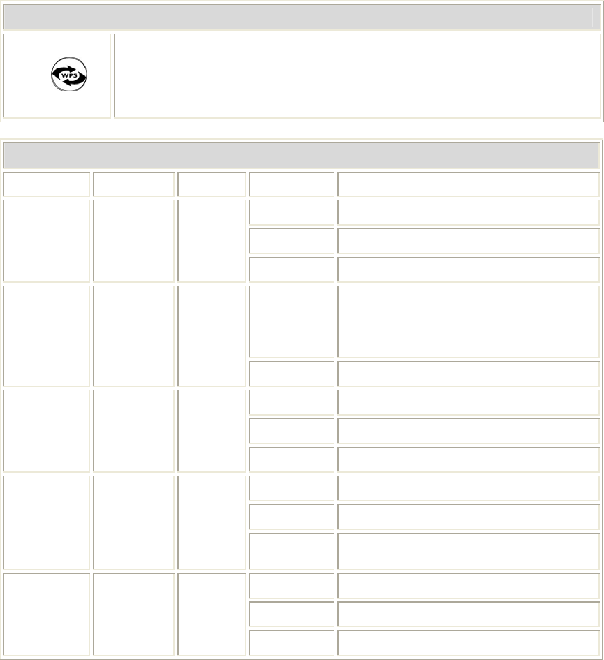
WPS button
WPS
Press the physical WPS button on the Wireless Router once, or go to
enable the WPS function via web configuration (Go to Wireless >
WPS page), then the LED will start to flash. Please make a
connection with other WPS supported device within 2 minutes.
LED Behavior
LED Printed Color Behavior Indication
OFF Power off
ON Power on
POWER PWR Green
Blinking Power saving mode starting
ON
Press reset button two seconds the
LED will on, keep on pressing more
than 3-5 seconds, the LED will start
to flash.
System SYS Green
Blinking System CPU is busy
OFF WLAN function off
ON WLAN link / active
Wireless
LAN WLAN Green
Blinking WLAN traffic transmitting
OFF WPS off
ON WPS active and connected
WPS WPS Green
Blinking WPS is enabled to make a
connection
OFF No Ethernet cable connecting
ON Ethernet cable connected
Ethernet Ethernet Green
Blinking Receiving/ sending data
Chapter 1: Introduction
5
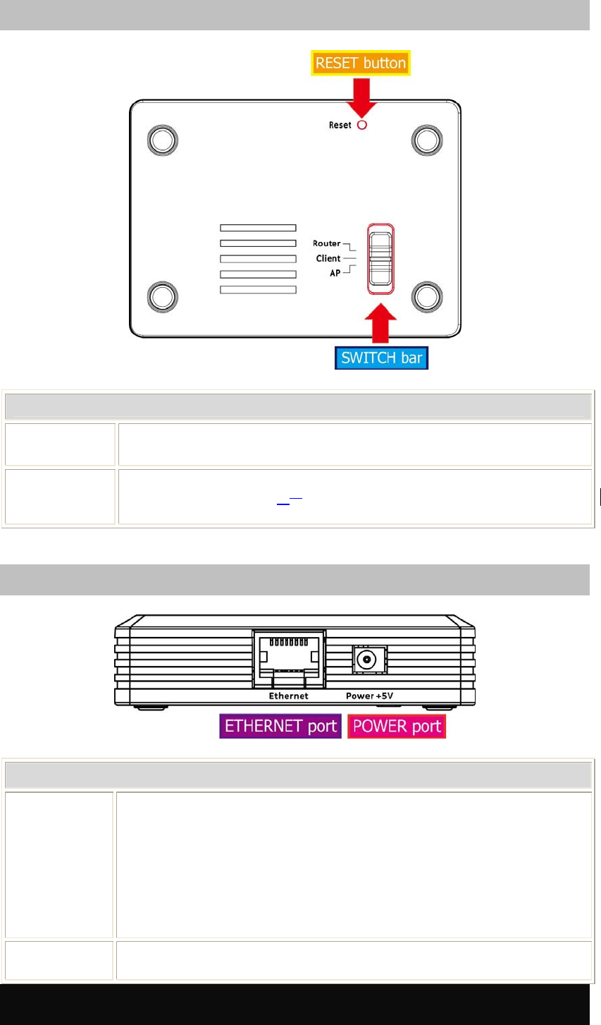
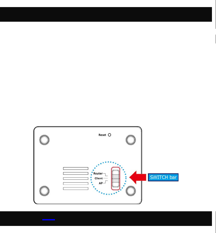
Bottom Switch
Reset button and switch bar
Reset Keep on pressing the Reset button more than 3 seconds, the
Wireless Router will set all setting back to factory default values.
Switch User need to MANUALLY switch the bar into the mode preferred,
Router, AP or Client mMode, then the device will reboot
automatically into the mode selected.
Side Panel
Ethernet and power ports
Ethernet
When the mode be set to AP or Client modes, use standard LAN
cables (RJ45 connectors) to connect your PCs to this port. If
required, any port can be connected to another hub. Any LAN port
will automatically function as an "Uplink" port when necessary.
When the mode be set to Router mode, connect the ADSL or
Cable Modem here with RJ45 cable. If your modem came with a
cable, use the supplied cable, otherwise, use a standard LAN
cable (RJ45 connectors).
Power (5V) Connect the supplied power adapter here.
Chapter 2: Operation Modes
6
Chapter 2: Operation
Modes
This device provides operational applications with Router, AP and Client modes, which are mutually
exclusive. This device is shipped with configuration that is functional right out of the box. If you want
to change the settings in order to perform more advanced configuration or even change the mode of
operation, you can manually switch to the mode you desire by the manufacturer as described in the
following sections. The default setting mode is Router mode.
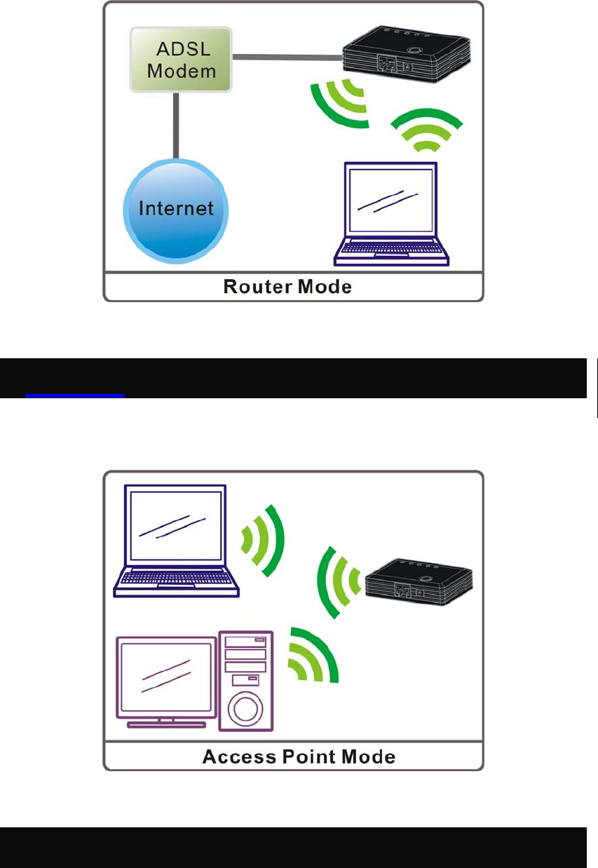
RouterW Mode
When set to Router mode, ensure you are using the wireless LAN interface, connect the Wireless
Router with computer via radio frequency. In this mode, the device is supposed to connect to internet
via ADSL/Cable Modem. Connect the ADSL modem to the Ethernet port of the Wireless Router by
Ethernet cable. After connected successfully, user can login the web page of the Wireless Router to set
up the Internet connection by using PPPoE, DHCP client, PPTP client , L2TP client or static IP.
Chapter 2: Operation Modes
7
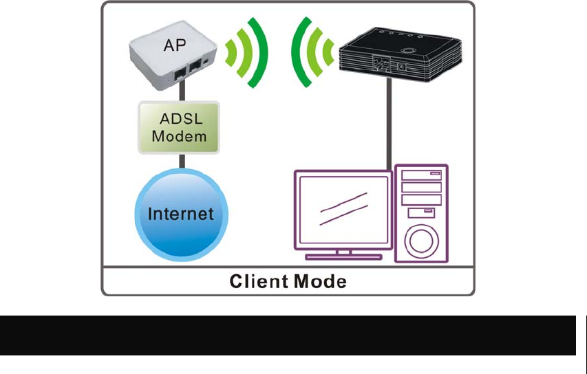
Access Point Mode
When acting as an Access Point (AP), this device connects all the stations (PC/notebook with wireless
network adapter) to a wireless network.
Client Mode
If set to Client (Infrastructure) mode, this device can work like a wireless station when it’s connected to
a computer so that the computer can send packets from wired end to wireless interface.
Chapter 2: Operation Modes
8

Chapter 3: Installation
9
Chapter 3: Installation
Hardware Connection
Chapter 3: Installation
10
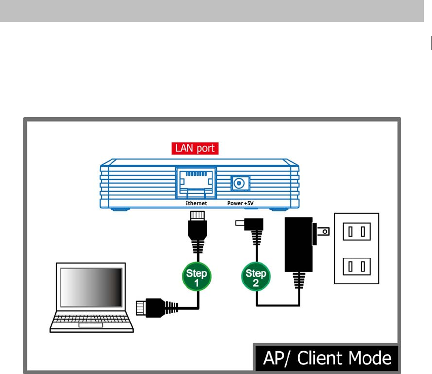
AP/ Client Mode
Connect via cable …
Step 1. Connect one end of the Ethernet cable to the Ethernet port(act as a LAN port here) of the
Wireless Router, another end to your PC or notebook.
Step 2. Then, connect the Wireless Router with a power to an outlet.
Chapter 3: Installation
11
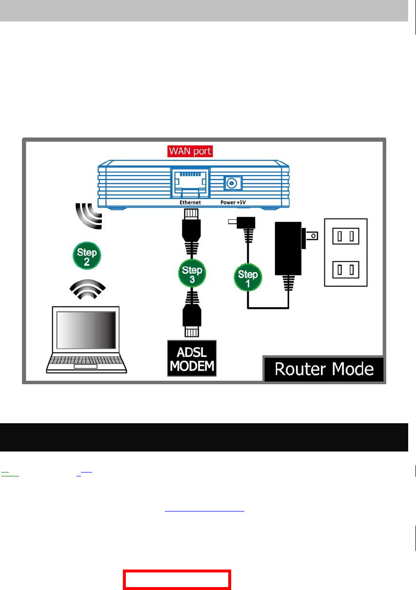
Router Mode
Connect via wireless…
Step 1. Power on the wireless router first, connect the Wireless Router with a power to an outlet.
Step 2. Then, connect the computer with the wireless router via wireless LAN interface.
Step 3. After make a connection and set up(please refer to TCP/IP Settings> WAN Interface
Setup) successfully, connect the ADSL or cable modem with an cable to the Ethernet
port(act as WAN port here). If your modem came with a cable, use the supplied cable.
Login
2.1. Make sure the c. Connection between your computer and Wireless Router setup successfully.
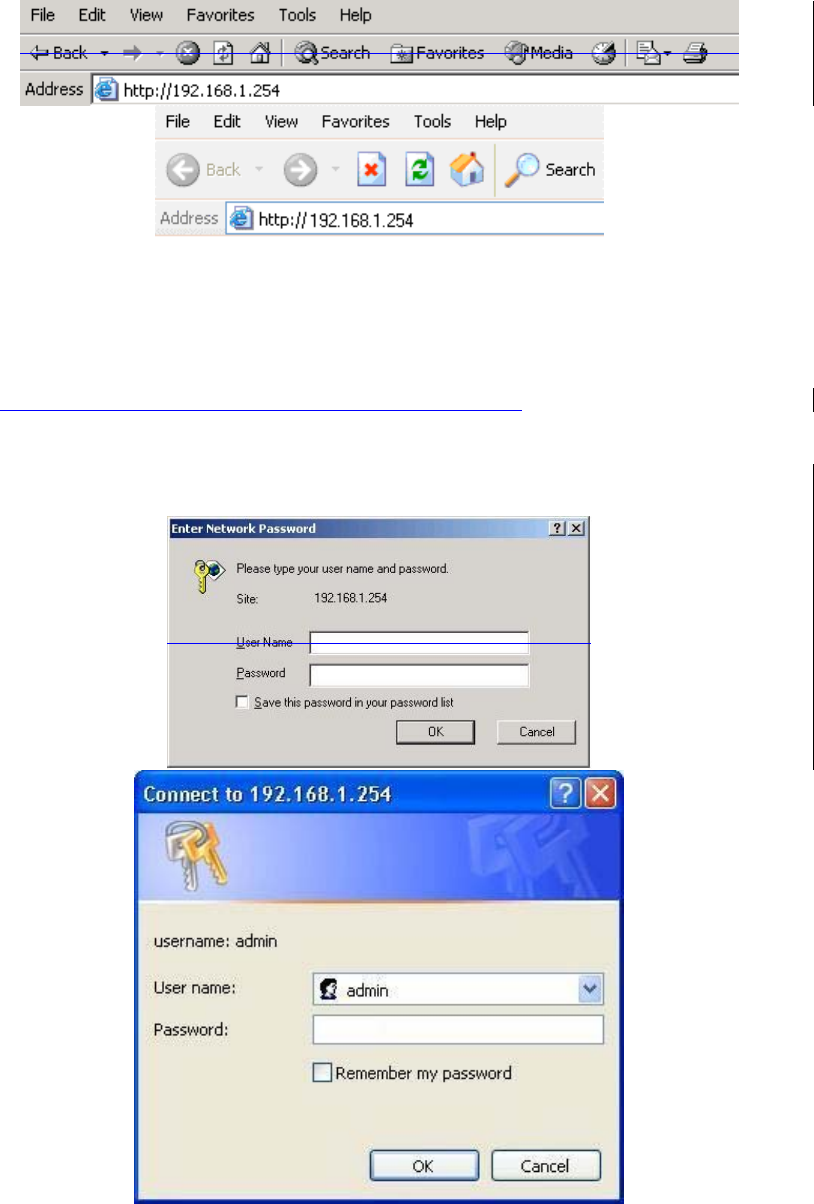
2. Start your Web Browser.
3. In the Address box, enter the IP address of the Wireless Router, as in this example, which uses the
Wireless Router's default IP address: http://192.168.1.254.
Chapter 3: Installation
12
4. After connected successfully, the following screen will show up. Simply enter the username
“admin” without password to login(case-sensitive).
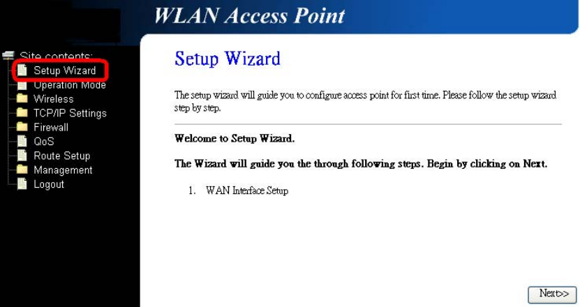
After login successfully, please click the Setup Wizard item that provides a primary configuration of
this device. You may enter each screen to change the default settings step by step.
Chapter 3: Installation
13
Chapter 3: Installation
14
If you cannot connect...
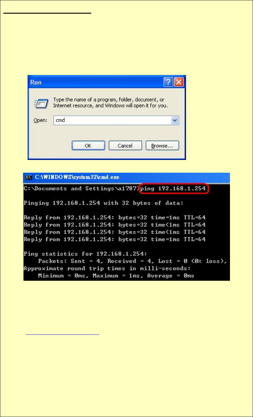
If the Wireless Router does not respond, please check following:
• The Wireless Router is properly installed and connection with computer is OK,
and it is already powered ON. You can test the connection by using the "Ping"
command:
• Please go to Start>Run…> Enter “cmd” command in the column to open
the MS-DOS window.
• Enter the command: ping 192.168.1.254
If no response is received, either the connection is not working, or your PC's IP
address is not compatible with the Wireless Router's IP address. (See next item.)
• If your PC is using a fixed IP address, its IP address must be within the range
192.168.1.1 to 192.168.1.253 to be compatible with the Wireless Router's default IP
Address of 192.168.1.254. Also, the Network Mask must be set to 255.255.255.0.
See Chapter 4 - PC Configuration for details on checking your PC's TCP/IP settings.
• Ensure that your PC and the Wireless Router are on the same network segment. (If
you don't have a router, this must be the case.)
• When set to AP/Client mode, ensure you are using the wired LAN interface,
connect the computer by Ethernet cable to the Ethernet port of the Wireless
Router.
• When set to Router mode, ensure you are using the wireless interface, connect the
Wireless Router with computer via radio frequency. The Wireless interface can only
be used if its configuration matches computer’s wireless settings.
Chapter 3: Installation
15

Chapter 3: Installation
16
Common Connection Types
Common Connection Types
Cable Modems
Type Details ISP Data required
Dynamic IP Address Your IP Address is allocated
automatically, when you connect to
you ISP.
Usually, none.
However, some ISP's may require
you to use a particular Hostname,
Domain name, or MAC (physical)
address.
Static (Fixed) IP
Address Your ISP allocates a permanent IP
Address to you.
IP Address allocated to you.
Some ISP's may also require you to
use a particular Hostname, Domain
name, or MAC (physical) address.
DSL Modems
Type Details ISP Data required
Dynamic
IP Address
Your IP Address is allocated
automatically, when you connect to you
ISP. None.
Static (Fixed)
IP Address Your ISP allocates a permanent IP
Address to you. IP Address allocated to you.
PPPoE You connect to the ISP only when
required. The IP address is usually
allocated automatically. User name and password.
PPTP
Mainly used in Europe.
You connect to the ISP only when
required. The IP address is usually
allocated automatically, but may be
Static (Fixed).
• PPTP Server IP Address.
• User name and password.
• IP Address allocated to you, if
Static (Fixed).
L2TP
Mainly used in Europe.
You connect to the ISP only when
required. The IP address is usually
allocated automatically, but may be
Static (Fixed).
• L2TP Server IP Address.
• User name and password.
• IP Address allocated to you, if
Static (Fixed).
Other Modems (e.g. Broadband Wireless)
Type Details ISP Data required
Dynamic
IP Address
Your IP Address is allocated
automatically, when you connect to you
ISP. None.
Chapter 4: Web Configuration
17
Static (Fixed)
IP Address Your ISP allocates a permanent IP
Address to you. IP Address allocated to you.
Chapter 4: Web
Configuration
After login successfully, please click the Setup Wizard item that provides a primary configuration of
this device. You may enter each screen to change the default settings step by step.
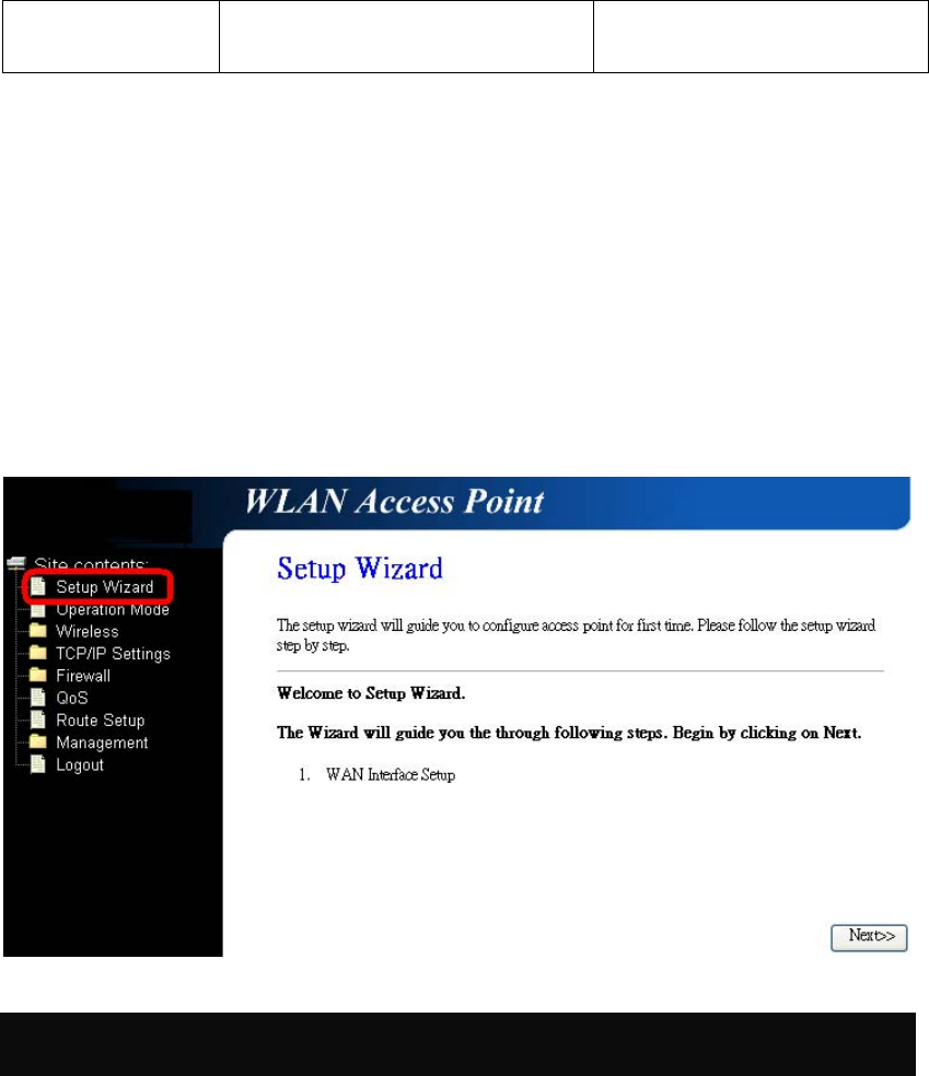
Setup Wizard
The setup wizard will guide you to configure access point for first time. Please follow the setup wizard
step by step.
Chapter 4: Web Configuration
18
Router Mode
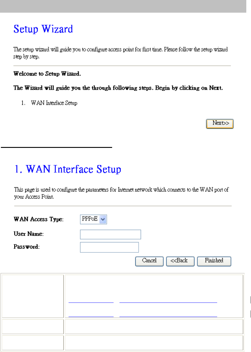
Step 1- WAN Interface Setup
User can select the WAN access type here for internet connection.
WAN Access Type If the PPPoE be selected, user have to set up the user name and
password according to the ISP that provided the related information.
User Name: Enter the username that provide by your ISP provider.
Maximum input is 32 alphanumeric characters (case sensitive).
Password: Enter the password that provide by your ISP provider.
Maximum input is 32 alphanumeric characters (case sensitive).
User Name Enter the username that provide by your ISP provider. Maximum input
is 32 alphanumeric characters (case-sensitive).
Password Enter the password that provide by your ISP provider. Maximum input
is 32 alphanumeric characters (case-sensitive).
Chapter 4: Web Configuration
19
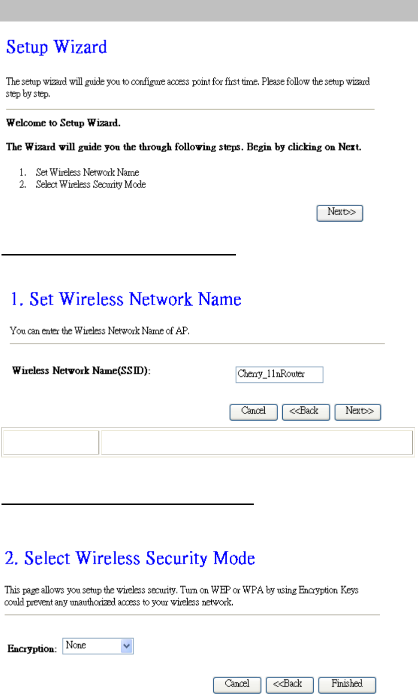
AP/Client Mode
Step 1- Set Wireless Network Name
User can setup the network name of the Wireless Router here.
Wireless Network
Name (SSID) A SSID is referred to a network name because essentially it is a name that
identifies a wireless network(case-sensitive).
Step 2- Select Wireless Security Mode
User can setup the security here, it is strongly recommended to set up security mode to prevent any
unauthorized accessing.
Chapter 4: Web Configuration
20
Encryption Select desired security type from the pull-down menu None, WEP, WPA,
WPA2 and WPA2-Mixed. The default setting is None. It is strongly
recommended to set up security mode (WEP, WPA, WPA2 and WPA2-
Mixed) to prevent any unauthorized accessing.
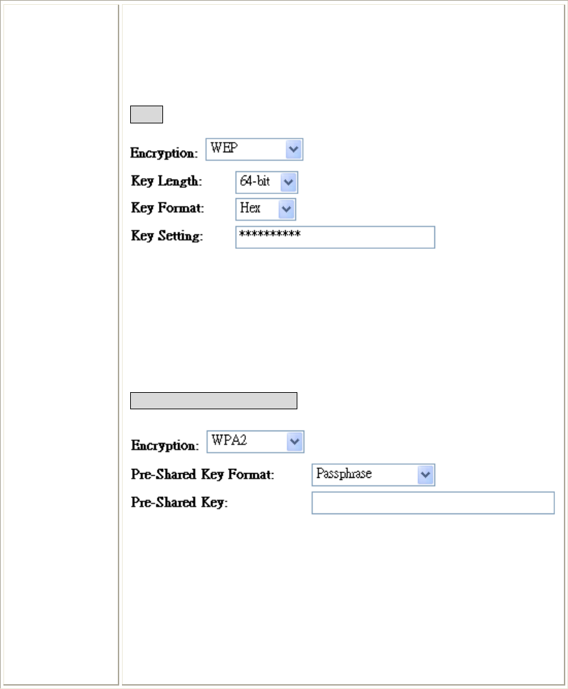
WEP
Key Length: Select key length 64-bit or 128-bit.
Key Format:
Hexadecimal (WEP 64 bits): 10 Hex characters (0~9, a~f).
Hexadecimal (WEP 128 bits): 26 Hex characters (0~9, a~f).
ASCII (WEP 64 bits): 5 ASCII characters (case-sensitive).
ASCII (WEP 128 bits): 13 ASCII characters (case-sensitive).
Key Setting: Enter the key in the key setting field.
WPA/ WPA2/ WPA2-Mixed
Pre-Shared Key Format: There are two formats for choice to set the Pre-
shared key, Passphrase and Hex (64 characters). If Hex is selected, users
will have to enter a 64 characters string. For easier configuration, the
Passphrase (at least 8 characters) format is recommended.
Pre-Shared Key : Pre-Shared Key serves as a password. Users may key in 8
to 63 characters string if you selected passphrase. Pre-shared key format to
set the passwords or leave it blank, in which the 802.1x Authentication will
be activated. Make sure the same password is used on client's end.
Chapter 4: Web Configuration
21
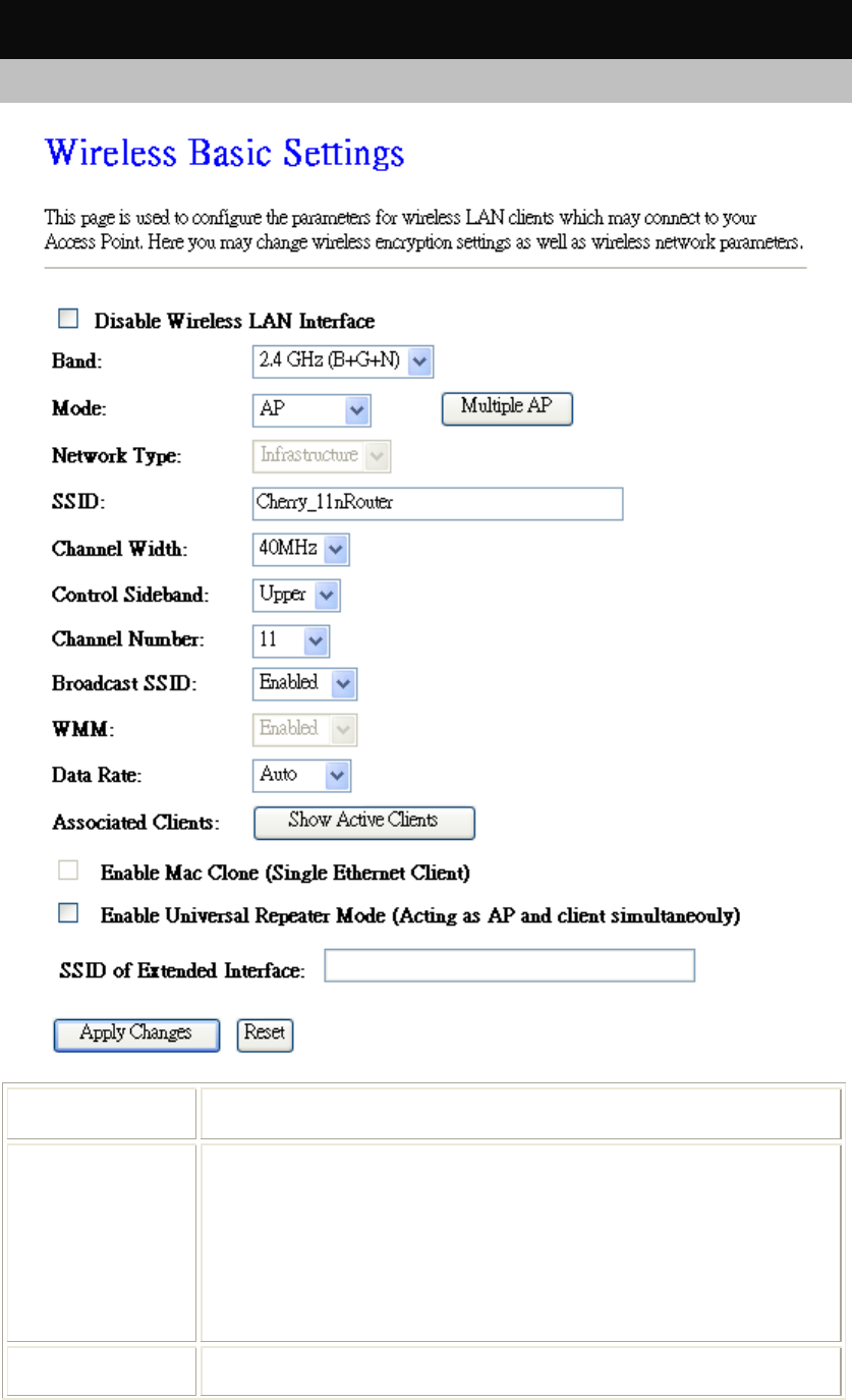
Wireless
Basic Settings
Disable Wireless
LAN Interface Check to disable the wireless function. If the wireless LAN interface be
disabled, the WLAN LED on the top will be off.
Band You can choose one mode of the following you need. The default is
2.4GHz (B+G+N) mode.
2.4GHz (B): 802.11b supported rate only.
2.4GHz (G): 802.11g supported rate only.
2.4GHz (N): 802.11n supported rate only.
2.4GHz (B+G): 802.11b supported rate and 802.11g supported rate.
2.4GHz (G+N): 802.11g supported rate and 802.11n supported rate.
2.4GHz (B+G+N): 802.11b, 802.11g and 802.11n supported rate.
Mode Under Router operation mode, user can select AP, WDS, and AP+WDS
from the
p
ull-down list. For AP mode
,
user can select AP
,
Client
,
WDS
Chapter 4: Web Configuration
22
and AP+WDS mode. Under Client mode, there is only Client mode can be
selected.
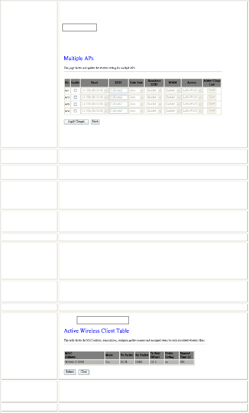
Multiple APs
This page shows and updates the wireless setting for multiple APs.
User can set up the multiple AP here. To enable one of the APs from 1~4,
then setup the wireless settings from the pull-down list.
Network Type If the mode be set to Client mode that the network type can be set to
Infrastructure or Ad hoc.
Network Name
(SSID) A SSID is referred to a network name because essentially it is a name that
identifies a wireless network(case-sensitive).
Channel Width This function will be available under 2.4GHz (N), 2.4GHz (G+N), 2.4GHz
(B+G+N) mode. Select 20MHz the channel number will be form 5~11 and
auto; Select 40MHz channel width the channel number will be form 1~11
and auto. Default is 40MHz.
Control Sideband This function will be available under 2.4GHz (N), 2.4GHz (G+N), 2.4GHz
(B+G+N) mode. Select upper or lower form the pull-down list, default is
upper.
Channel Number The channel number base on the channel width you select.
Broadcast SSID Enabled: This Wireless Router will broadcast its network name(SSID) to
stations.
Disabled: This Wireless Router will hide the network name to stations. If
stations want to connect to this Wireless Router, this Router’s network
name(SSID) should be known in advance to make a connection.
WMM The Wi-Fi Multiple Media function is available under 2.4GHz (B), 2.4GHz
(G) and 2.4GHz (B+G) band, and it is disabled under 2.4GHz (N), 2.4GHz
(G+N) and 2.4GHz (B+G+N) band.
Data Rate There are several data rate that you can select from the pull-down menu.
Associated Clients Click Show Active Clients button to show all connected clients.
Enable Mac Clone
(Single Ethernet
Client) This function will be enabled under Client mode.
Enable Universal This function will be enabled under AP mode.
Chapter 4: Web Configuration
23
Repeater Mode
(Acting as AP and
client
simultaneously)
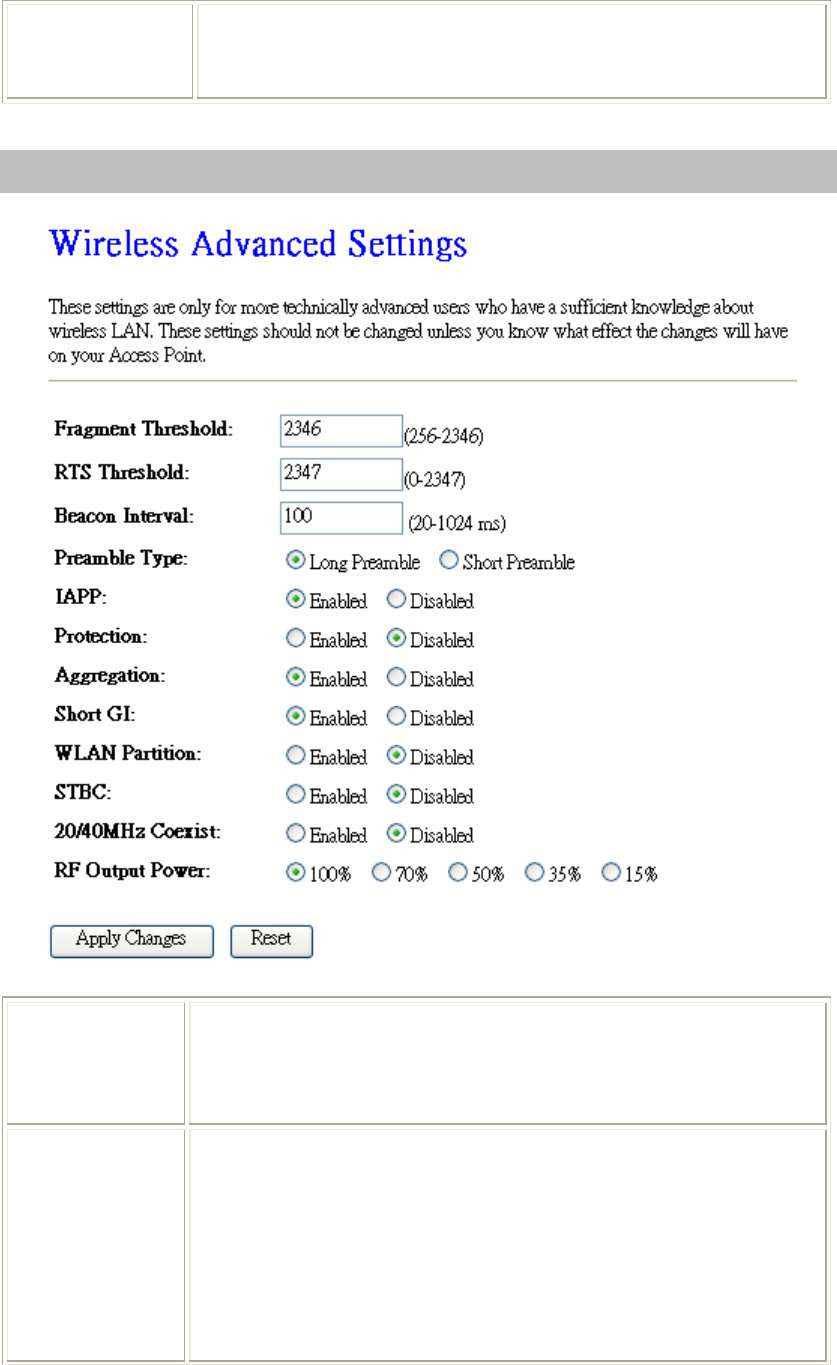
Advanced Settings
Fragment
Threshold Fragmentation mechanism is used for improving the efficiency when high
traffic flows along in the wireless network. If the 802.11g MIMO Wireless
Router often transmit large files in wireless network, you can enter new
Fragment Threshold value to split the packet. The value can be set from
256 to 2346. The default value is 2346.
RTS Threshold RTS Threshold is a mechanism implemented to prevent the “Hidden Node”
problem. If the “Hidden Node” problem is an issue, please specify the
packet size. The RTS mechanism will be activated if the data size exceeds
the value you set.
Warning: Enabling RTS Threshold will cause redundant network overhead
that could negatively affect the throughput performance instead of providing
a remedy.
This value should remain at its default setting of 2347. Should you
encounter inconsistent data flow, only minor modifications of this value are
recommended.
Chapter 4: Web Configuration
24
Beacon Interval Beacon Interval is the amount of time between beacon transmissions.
Before a station enters power save mode, the station needs the beacon
interval to know when to wake up to receive the beacon. Range 20-1024 ms,
default is 100.
Preamble Type A preamble is a signal used in wireless environment to synchronize the
transmitting timing including Synchronization and Start frame delimiter.
You can select Long or Short for the preamble type.
IAPP Select Enabled or Disabled to execute this function.
Protection Select Enabled or Disabled to execute the security function.
Aggregation Select Enabled or Disabled to execute this function.
Short GI Select Enabled or Disabled to execute this function.
WLAN Partition Select Enabled or Disabled to execute this function.
STBC Select Enabled or Disabled to execute this function. The default is Disabled.
20/40MHz
Coexist Select Enabled or Disabled to execute this function. The default is Disabled.
RF Output Power Select the transmitting power rate 100%, 70%, 50%, 35%, 15%.
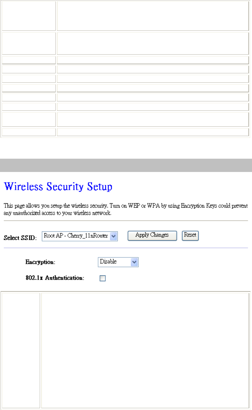
Security
Security
Mode
Select desired security type from the pull-down menu Disable, WEP, WPA,
WPA2 and WPA2-Mixed. The default setting is Disable. It is strongly
recommended to set up security mode (WEP, WPA, WPA2 and WPA2-Mixed) to
prevent any unauthorized accessing.
Note:
WPA and WPA-PSK only support TKIP and AES as encryption method.
Shared Key only supports WEP as encryption method.
AUTO(Open/Shared) means AP can accept STA connect to it using OPEN-
WEP or SHARED-WEP.
Chapter 4: Web Configuration
25
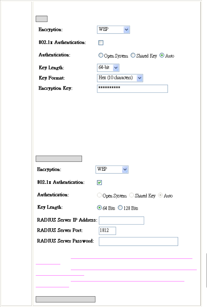
WEP
802.1x Authentication: Check the box to enable the 802.1x authentication.
Authentication: Select Open System, Shared Key or Auto.
Key Length: select key length 64-bit or 128-bit.
Key Format:
Hexadecimal (WEP 64 bits): 10 Hex characters (0~9, a~f).
Hexadecimal (WEP 128 bits): 26 Hex characters (0~9, a~f).
ASCII (WEP 64 bits): 5 ASCII characters (case-sensitive).
ASCII (WEP 128 bits): 13 ASCII characters (case-sensitive).
Encryption Key: Enter the key in the key setting field.
802.1x Authentication
Key Length: select key length 64 Bits or 128 Bits.
RADIUS Server IP Address: Enter the RADIUS Server’s IP Address provided
by your ISP.
RADIUS Server Port: Enter the RADIUS Server’s port number provided by your
ISP. The default is 1812.
RADIUS Server Password: Enter the password that the AP shares with the
RADIUS Server.
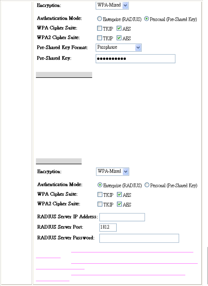
WPA/ WPA2/ WPA2-Mixed
Chapter 4: Web Configuration
26
Personal (Pre-Shared Key)
Authentication Mode: Select Enterprise (RADIUS) or Personal (Pre-Shared Key)
mode.
WPA Cipher Suite: Here supported AES only.
WPA2 Cipher Suite: Here supported AES only.
Pre-Shared Key Format: There are two formats for choice to set the Pre-shared
key, Passphrase and Hex (64 characters). If Hex is selected, users will have to
enter a 64 characters string. For easier configuration, the Passphrase (at least 8
characters) format is recommended.
Pre-Shared Key : Pre-Shared Key serves as a password. Users may key in 8 to
63 characters string if you selected passphrase. Pre-shared key format to set the
passwords or leave it blank, in which the 802.1x Authentication will be activated.
Make sure the same password is used on client's end.
Enterprise (RADIUS)
RADIUS Server IP Address: Enter the RADIUS Server’s IP Address provided
by your ISP.
RADIUS Server Port: Enter the RADIUS Server’s port number provided by your
ISP. The default is 1812.
RADIUS Server Password: Enter the password that the AP shares with the
RADIUS Server.
Chapter 4: Web Configuration
27
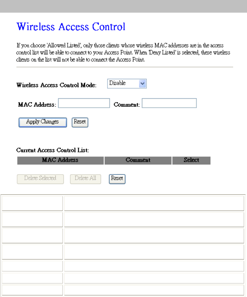
Access Control
Wireless Access
Control Mode Select Allow Listed or Deny Listed form the pull-down menu to enable
access control function. Default setting is Disabled.
MAC Address Enter the MAC address (12 characters) of a station that is allowed to
access this Wireless Router.
Comment You may enter up to 20 characters as a remark to the previous MAC
address.
Current Access
Control List This table displays you the station MAC information.
Delete Selected Click Delete Selected to delete items which are selected.
Delete All Click Delete All to delete all the items.
Reset Click Reset to rest.
Chapter 4: Web Configuration
28
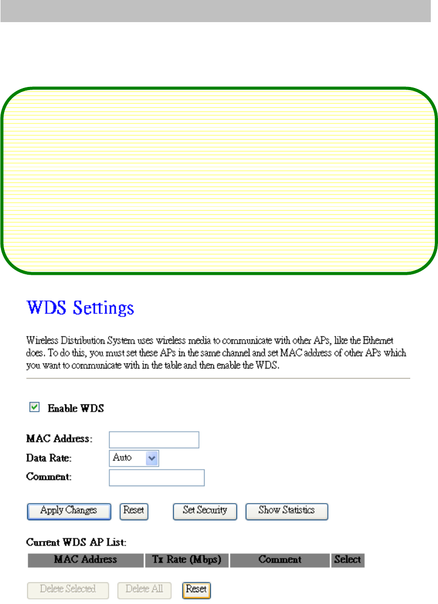
WDS Settings
Wireless Distribution System uses wireless media to communicate with other APs, like the Ethernet
does. To do this, you must set these APs in the same channel and set MAC address of other APs which
you want to communicate with in the table and then enable the WDS.
To use WDS function:
1. The APs must support WDS function.
2. To set the same SSID (Network name).
3. The channel must be set to the same on the APs.
4. To set the same Wireless MAC address (BSSID) on the APs.
5. To set same security (WEP or WPA) on the APs.
Note !
To setup WDS must use the same wireless products (the same model will be
better); due to different wireless products might support different WDS settings.
Thus, it is suggested that to use the same wireless products that support WDS
function.
Chapter 4: Web Configuration
29
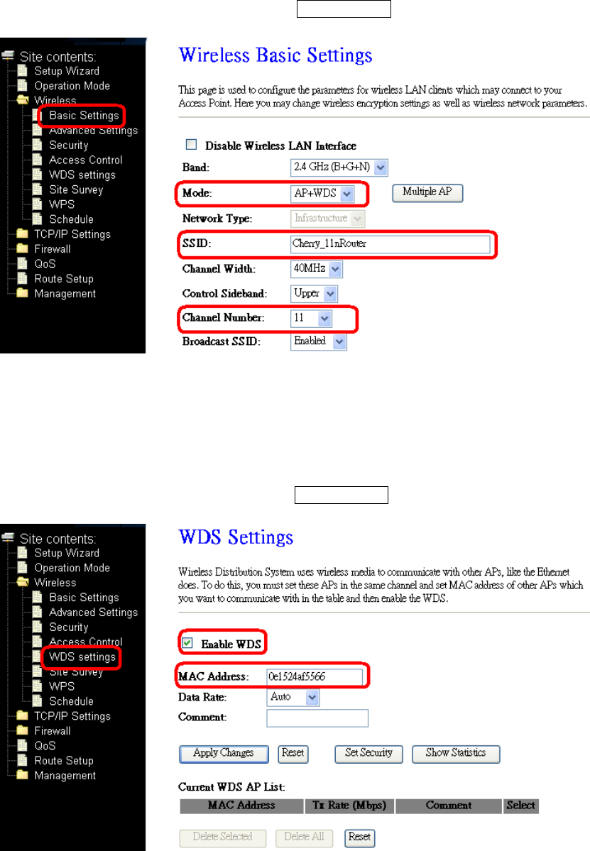
Step 1. Users would like to set up the WDS function, please go to Wireless > Basic Settings page
to set up the Mode into WDS or AP+ WDS (Repeater) mode, and set the APs into the same
SSID (Network Name) and Channel Number(If set to WDS mode, the SSID do not need
to change). After setting up, please click Apply Changes button to execute.
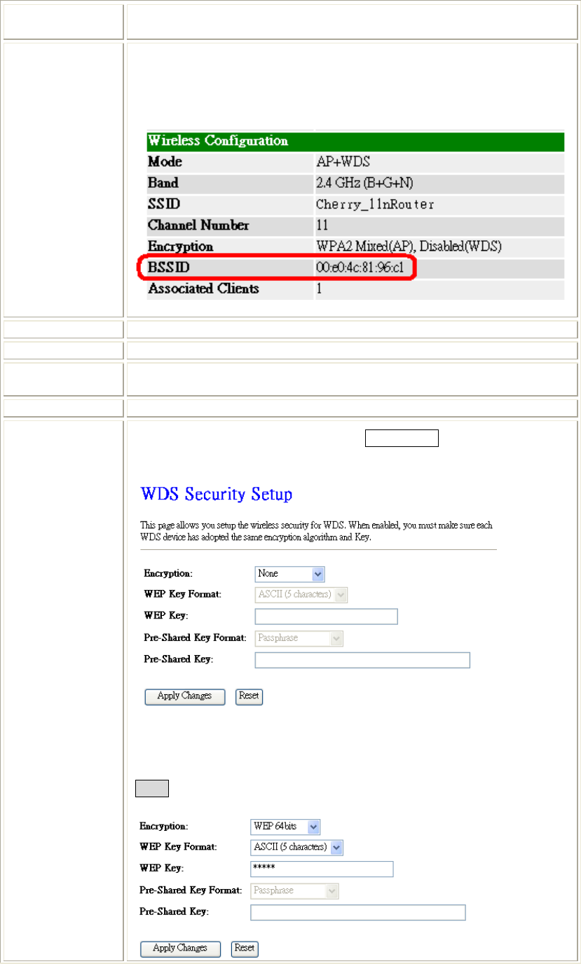
Step 2. Then go back to Wireless > WDS Settings page to check Enable WDS box to enable WDS
function and then enter Wireless MAC address (please go to Management> Status>
Wireless Configuration> BSSID to make sure the BSSID) 12 characters to each other to
make the WDS connection. Please click Apply Changes button to execute.
Chapter 4: Web Configuration
30
Enable WDS Check the box to enable the WDS function.
MAC Address
MAC Address: Enter the Wireless BSSID (MAC) 12 characters of the
wireless AP that you want to connect with. To check your wireless router’s
MAC address, please go to Status > Wireless Configuration to find your
BSSID (Wireless MAC address.)
Data Rate Select the data rate form the pull-down list.
Comment Enter a description for the device.
Apply Changes After completing the settings on this page, click Apply changes button to
save the settings.
Reset Click Reset to restore to default values.
Set Security Enable the WDS function and then click Set Security button to set up the
WDS security.
Encryption: Select the encryption type None, WEP 64 bits, WEP 128 bits,
and WPA2 from the pull-down menu.
WEP
Chapter 4: Web Configuration
31
WEP Key Format: For WEP 64 bits and WEP 128 bits encryption type,
the selection of WEP Key Format are Hex and ASCII.
WEP Key: If select Hex if you are using hexadecimal numbers (0-9, or A-F).
Select ASCII if you are using ASCII characters (case-sensitive).
Hexadecimal (WEP 64 bits): 10 Hex characters (0~9, a~f).
Hexadecimal (WEP 128 bits): 26 Hex characters (0~9, a~f).
ASCII (WEP 64 bits): 5 ASCII characters (case-sensitive).
ASCII (WEP 128 bits): 13 ASCII characters (case-sensitive).
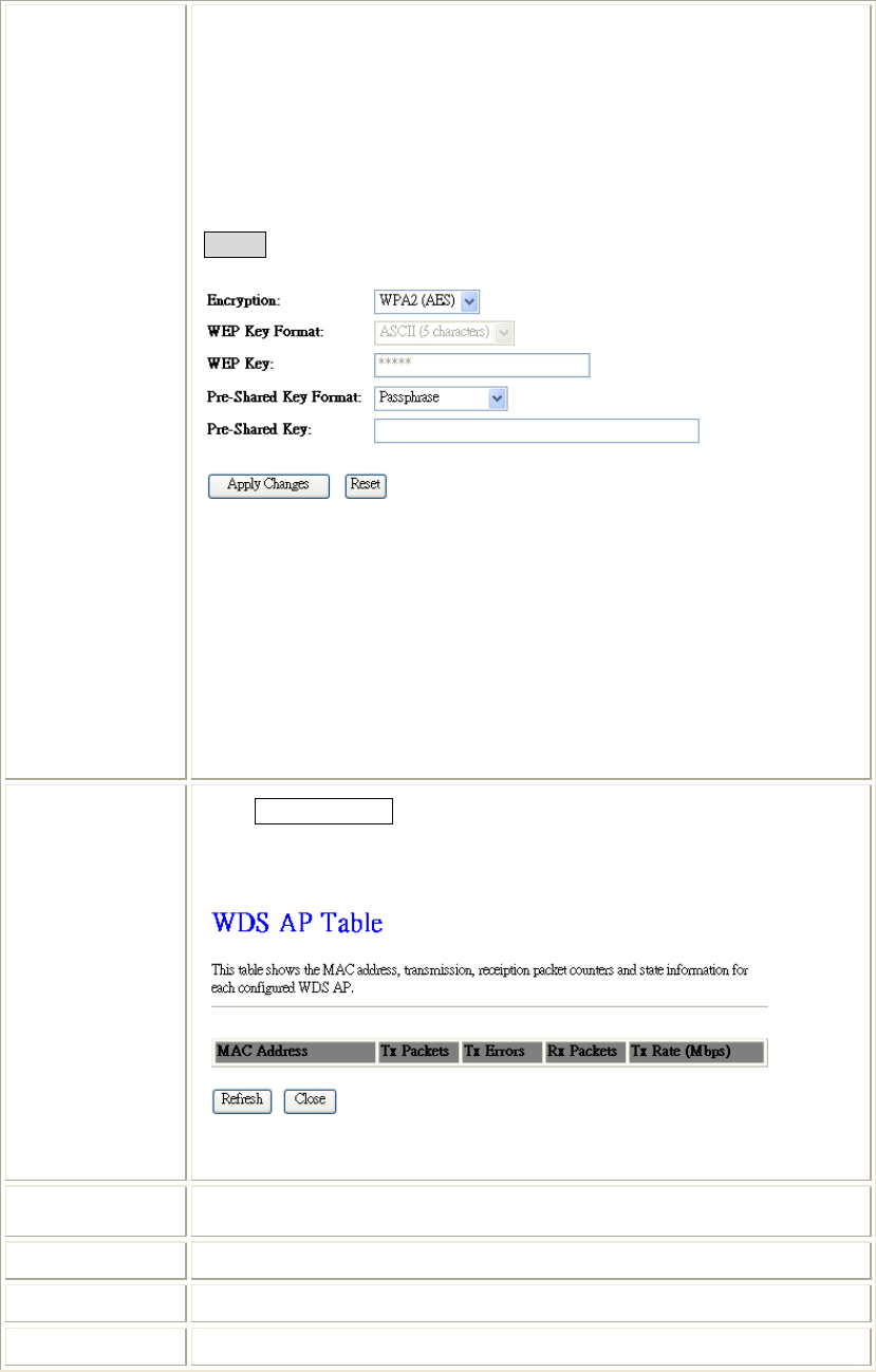
WPA2
Pre-Shared Key Format: The Pre-shared Key Format will be enabled
when WPA (TKIP) and WPA2 (AES) encryption be selected. There are
two formats for choice to set the Pre-shared key, Passphrase and Hex (64
characters). If Hex is selected, users will have to enter a 64 characters
string. For easier configuration, the Passphrase (at least 8 characters) format
is recommended.
Pre-Shared Key: Pre-Shared-Key serves as a password. Users may key in 8
to 63 characters string to set the passwords or leave it blank, in which the
802.1x Authentication will be activated. Make sure the same password is
used on client's end.
Show Statistics Click Show Statistics to show the current WDS AP table. This table shows
the MAC address, transmission packets and errors, reception packets and Tx
Rate (Mbps) counters for each configured WDS AP.
Refresh: Click to renew the counters information.
Close: Click to leave the screen.
Current WDS
AP List Here shows the current WDS AP information.
Delete Selected Click Delete Selected to delete the selected AP information.
Delete All Click Delete All to delete all the items.
Reset Click Reset to restore the settings.
Chapter 4: Web Configuration
32
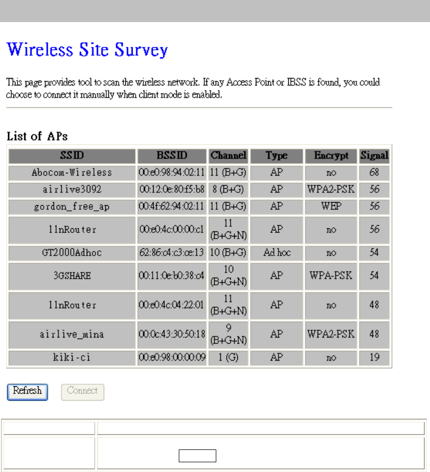
Site Survey
Refresh Check this button to renew all the listed access point.
Connect Under the client mode and select a site that you would like to communicate,
and then click the Connect button.
Chapter 4: Web Configuration
33
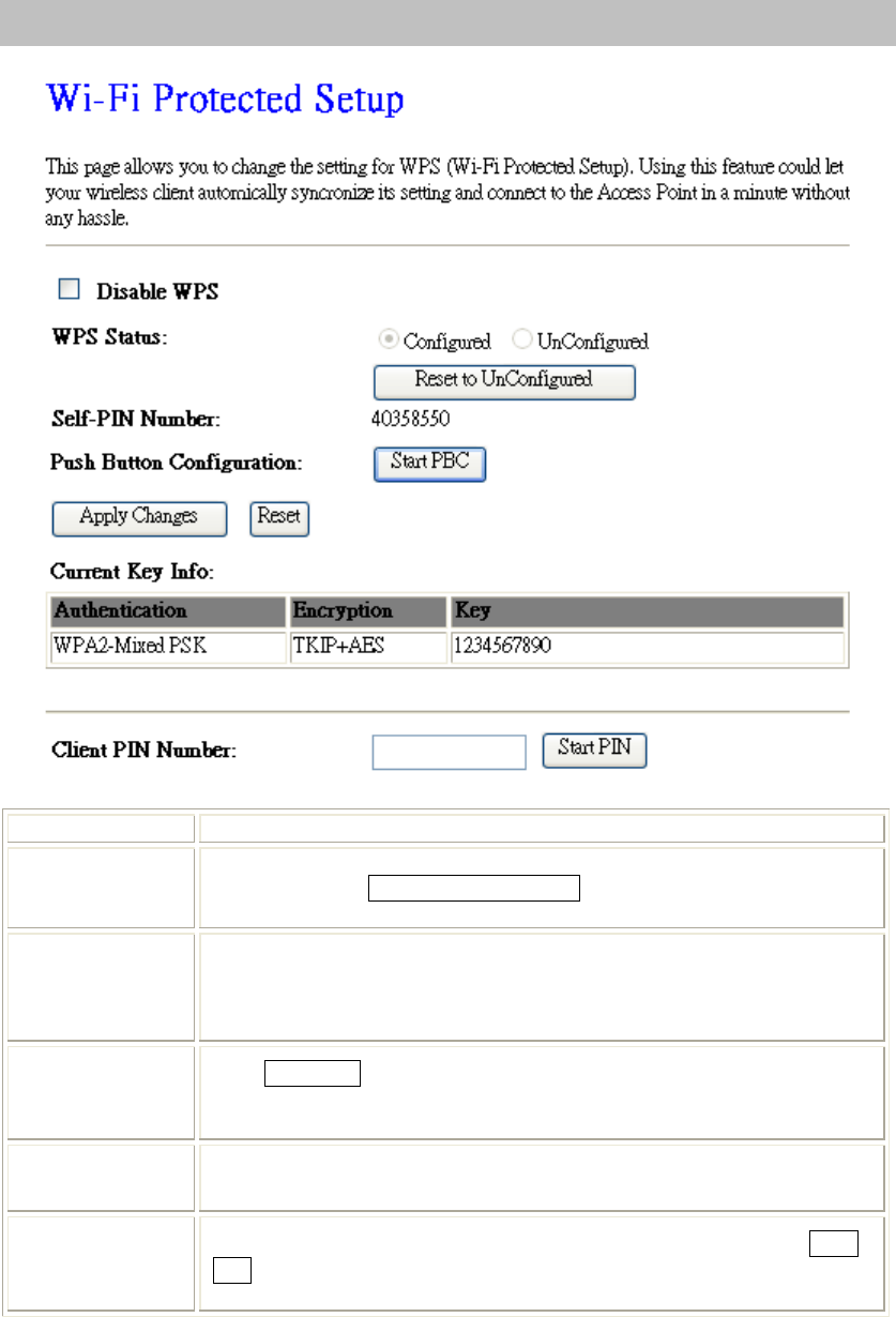
WPS
Disable WPS Check the box to disable the WPS function, default setting is enabled.
WPS Status Here shows the current status of the WPS function. Default setting is
Configured, click Reset to UnConfigured to re-configured the WPS
connection.
Self-PIN Number Here shows the 8-digit numbers PIN code of the router itself.
Enter the Self-PIN Number to client (Registrar) end and click the PIN
button at the client end to make a WPS connection. It will connect with the
wireless router within two minutes and get IP address.
Push Button
Configuration Click Start PBC button (or press the physical WPS button on the Wireless
Router once), meanwhile, the client should also click the PBC button
simultaneously within 2 minutes.
Current Key Info This table shows the security status of the Wireless Router. If user would
like to set up the security, please go to Wireless > Security.
Client PIN
Number Enter the client(Enrollee) PIN code into the blank field then click the Start
PIN button to make a WPS connection with client. Then, the wireless router
will connect to client within 2 minutes and get IP address.
Chapter 4: Web Configuration
34
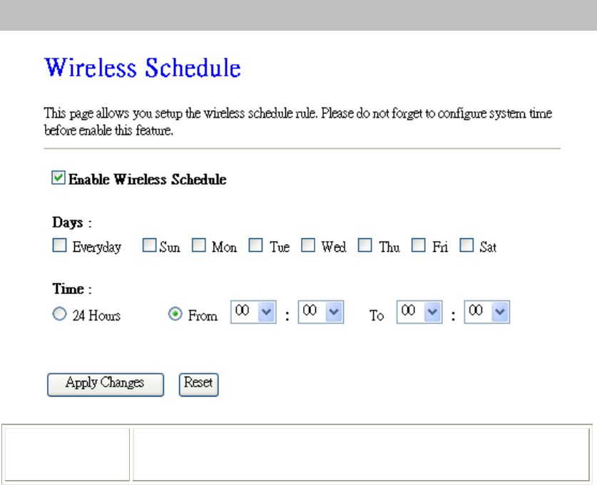
Schedule
Enable Wireless
Schedule Check the box to enable the schedule function. Set up the time to schedule
the wireless access rule. Select the day and time you want to enable the
wireless function.
Chapter 4: Web Configuration
35
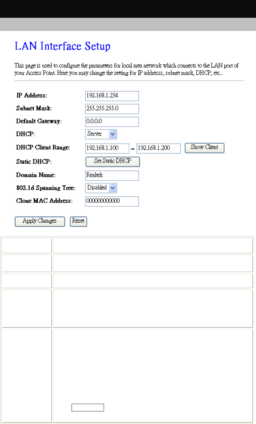
TCP/IP Settings
LAN Interface
IP Address Shows the IP address of the Wireless Router (Default IP address is
192.168.1.254.)
Subnet Mask The subnet mask of the Wireless Router (Default subnet mask is
255.255.255.0.)
Default
Gateway Enter the Gateway IP address here.
DHCP Disable: Select to disable this Wireless Router to distribute IP addresses to
connected clients.
Server: Select to enable this Wireless Router to distribute IP Addresses
(DHCP Server) to connected clients. And the following field will be activated
for you to enter the starting IP address.
DHCP Client
Range The starting address of this local IP network address pool. The pool is a piece
of continuous IP address segment, the device will distribute IP addresses from
192.168.1.100 to 192.168.1.200 to all the computers in the network that
request IP addresses from DHCP server (Router). The end IP address
maximum is 253.
Note: If “Continuous IP address pool starts” is set at 192.168.1.1 and the
“Number of IP address in pool end” is 253, the device will distribute IP
addresses from 192.168.1.100 to 192.168.1.253 to all the computers in the
network that request IP addresses from DHCP server (Router).
Click Show Client button to show Active DHCP Client Table. The table
shows assigned IP address, MAC address and time expired for each client.
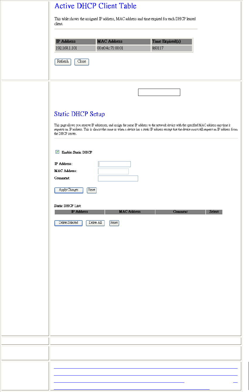
Chapter 4: Web Configuration
36
Refresh: Click this button to refresh the table.
Close: Click this button to close the window.
Static DHCP Check the box to enable the Static DHCP function, default setting is disabled.
When set to enabled, user can click Set Static DHCP button to set the Static
DHCP function.
IP Address: Enter the fixed IP address that DHCP Server assigned to a
certain connected station.
MAC Address: Enter the MAC address of a certain station, and then the
DHCP Server will to distribute a fixed IP address to the station automatically
once they connected.
Comment: You can enter a comment to description above IP address or MAC
address.
Apply Changes: After completing the settings on this page, click Apply
changes button to save the settings.
Reset: Click Reset to restore to default values.
Static DHCP List: Here shows the static IP address that have been assigned
according to the MAC address.
Delete Selected: Click Delete Selected to delete items which are selected.
Delete All: Click Delete All button to delete all the items.
Reset: Click Reset button to rest.
Domain Name Enter the network area name here.
802.1d
Spanning Tree Select Disabled or Enabled form the pull-down list.
Clone MAC
Address Your ISP may require a particular MAC address in order for you to connect to
the Internet. This MAC address is the PC’s MAC address that your ISP had
originally connected your Internet connection to. Type in the MAC address to
replace the WAN MAC address with the MAC address of that PC.
Chapter 4: Web Configuration
37
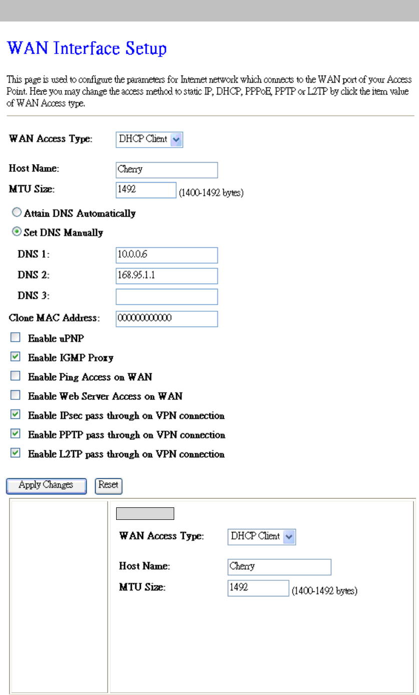
WAN Interface
WAN Access Type
DHCP Client
If the DHCP Client connection be selected, the PC will obtain the IP
address automatically.
Host Name: Enter the network area name in the column.
MTU Size: The most appropriate MTU (Maximum Transmission Unit)
namely the maximum packet size, the default value is 1492 for your
application. Reducing the packet size can help connecting to certain web
sites or speeding up packet transfer rate. If the incorrect packet size is
entered, you may not be able to open certain web sites.
Chapter 4: Web Configuration
38
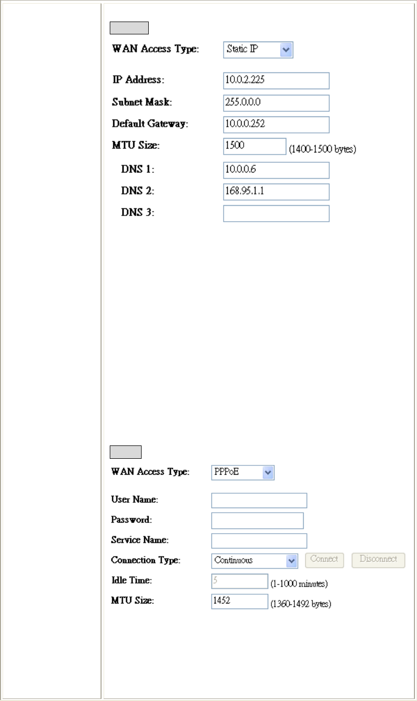
Static IP
If the Static IP be selected, user have to set up the IP address, subnet
mask and default gateway according to the ISP (Internet Service
Provider) that provided the related information.
IP Address: Enter the WAN IP address provided by your ISP here.
Subnet Mask: Enter the subnet mask here.
Default Gateway: Enter the default gateway IP address provided by
your ISP here.
MTU Size: The most appropriate MTU (Maximum Transmission Unit)
namely the maximum packet size. Reducing the packet size can help
connecting to certain web sites or speeding up packet transfer rate. If the
incorrect packet size is entered, you may not be able to open certain web
sites.
DNS 1: Enter the DNS server IP address(es) provided by your ISP, or
you can specify your own preferred DNS server IP address(es).
DNS 2/ DNS 3: These servers are optional. You can enter another DNS
server’s IP address as a backup. DNS 2 and 3 servers will be used when
the DNS 1 server fails.
PPPoE
If the PPPoE be selected, user have to set up the user name and
password according to the ISP that provided the related information.
User Name: Enter the username that provide by your ISP provider.
Maximum input is 32 alphanumeric characters (case sensitive).
Password: Enter the password that provide by your ISP provider.
Maximum input is 32 alphanumeric characters (case sensitive).
Service Name: Enter the Internet service provider name in the column.
Chapter 4: Web Configuration
39
Connection Type: Select the connection type Continuous, Connect on
Demand or Manual from the pull-down menu. If selected Manual user
can click Connect button to make a connection.
Idle Time: It represents that the device will idle after the minutes you
set. The time must be set between 1~1000 minutes. Default value of idle
time is 5 minutes. This function will be available when the Connection
Type is selected to Connect on Demand.
MTU Size: The most appropriate MTU (Maximum Transmission Unit)
namely the maximum packet size, the default value is 1452 for your
application. Reducing the packet size can help connecting to certain web
sites or speeding up packet transfer rate. If the incorrect packet size is
entered, you may not be able to open certain web sites.
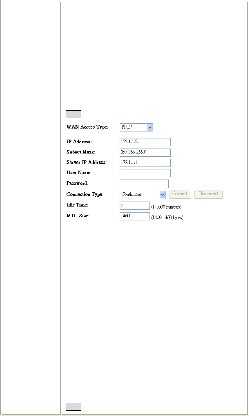
PPTP
If the PPTP be selected, user have to set up the server IP address, user
name and password according to the ISP that provided the related
information.
IP Address: Enter the WAN IP address provided by your ISP here.
Subnet Mask: Enter the subnet mask here.
Server IP Address: Enter the PPTP Server IP Address in this column.
User Name: Maximum input is 20 alphanumeric characters (case
sensitive).
Password: Maximum input is 32 alphanumeric characters (case
sensitive).
Connection Type: Select the connection type Continuous, Connect on
Demand or Manual from the pull-down menu. If selected Manual user
can click Connect button to make a connection.
Idle Time: It represents that the device will idle after the minutes you
set. The time must be set between 1~1000 minutes. Default value of idle
time is 5 minutes. This function will be available when the Connection
Type is selected to Connect on Demand.
MTU Size: The most appropriate MTU (Maximum Transmission Unit)
namely the maximum packet size, the default value is 1460 for your
application. Reducing the packet size can help connecting to certain web
sites or speeding up packet transfer rate. If the incorrect packet size is
entered, you may not be able to open certain web sites.
L2TP
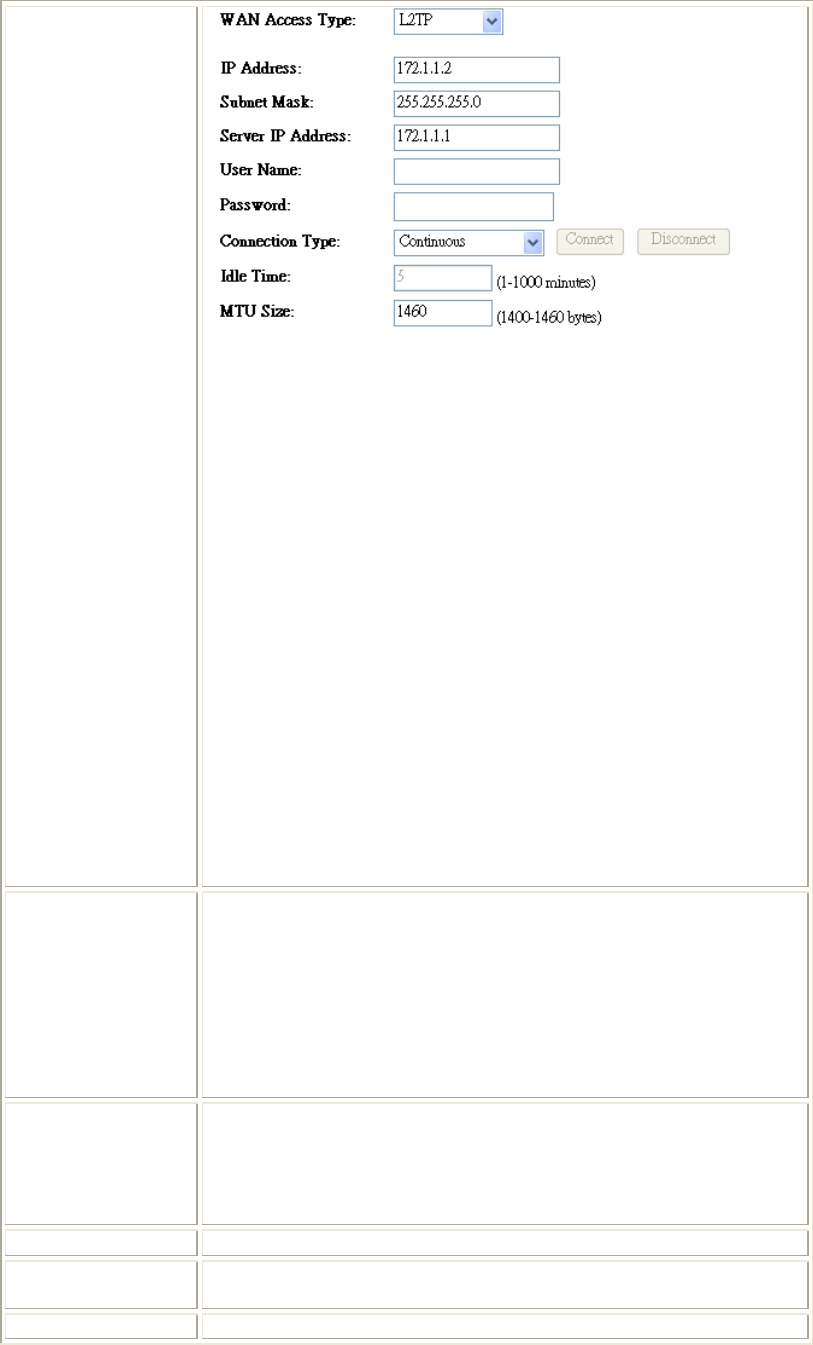
Chapter 4: Web Configuration
40
If the L2TP be selected, user have to set up the server IP address, user
name and password according to the ISP that provided the related
information.
IP Address: Enter the WAN IP address provided by your ISP here.
Subnet Mask: Enter the subnet mask here.
Server IP Address: Enter the L2TP Server IP Address in this column.
User Name: Maximum input is 20 alphanumeric characters (case
sensitive).
Password: Maximum input is 32 alphanumeric characters (case
sensitive).
Connection Type: Select the connection type Continuous, Connect on
Demand or Manual from the pull-down menu. If selected Manual user
can click Connect button to make a connection.
Idle Time: It represents that the device will idle after the minutes you
set. The time must be set between 1~1000 minutes. Default value of idle
time is 5 minutes. This function will be available when the Connection
Type is selected to Connect on Demand.
MTU Size: The most appropriate MTU (Maximum Transmission Unit)
namely the maximum packet size, the default value is 1460 for your
application. Reducing the packet size can help connecting to certain web
sites or speeding up packet transfer rate. If the incorrect packet size is
entered, you may not be able to open certain web sites.
Attain DNS
Automatically
Set DNS
Manually
DNS 1
DNS 2
DNS3
Select to Attain DNS Automatically or select Set DNS Manually to
set the DNS server IP address at the following DNS 1~3 columns.
Default setting is Attain DNS Automatically.
Enter the DNS server IP address(es) provided by your ISP, or you can
specify your own preferred DNS server IP address(es).
DNS 2 server is optional. You can enter another DNS server’s IP
address as a backup. DNS 2 server will be used when the DNS 1 server
fails.
Clone MAC
address
Your ISP may require a particular MAC address in order for you to
connect to the Internet. This MAC address is the PC’s MAC address
that your ISP had originally connected your Internet connection to. Type
in this Clone MAC address in this section to replace the WAN MAC
address with the MAC address of that PC.
Enable uPNP… Check to enable the listed functions.
Apply Changes After completing the settings on this page, click Apply changes button
to save the settings.
Reset Click Reset to restore to default values.
Chapter 4: Web Configuration
41
Firewall
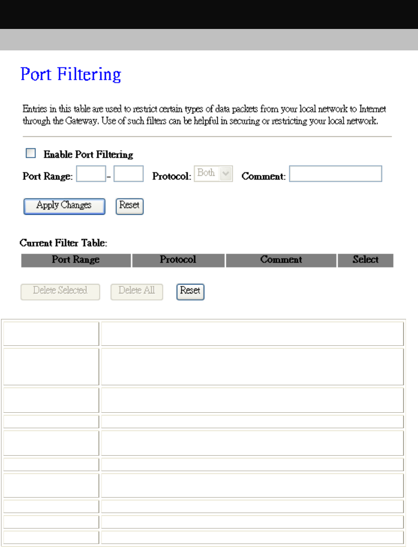
Port Filtering
Enable Port
Filtering Check to enable Port Filtering function.
Port Range Enter the beginning of the range of port numbers used by the service. If
the service uses a single port number, enter it in both the start and finish
fields.
Protocol Select the protocol (TCP, UDP or Both) used to the remote system or
service.
Comment You may key in a description MAC address.
Apply Changes After completing the settings on this page, click Apply Changes button
to save the settings.
Reset Click Reset button to restore to default values.
Current Filter
Table Shows the current Port Forwarding information.
Delete Selected Click Delete Selected button to delete items which are selected.
Delete All Click Delete All button to delete all the items.
Reset Click Reset button to rest.
Chapter 4: Web Configuration
42
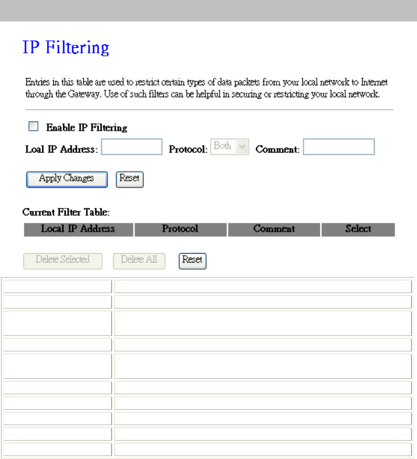
IP Filtering
Enable IP Filtering Check to enable IP filtering function.
Local IP Address Enter the local computer’s IP address.
Protocol Select the protocol (TCP, UDP or Both) used to the remote system or
service.
Comment You may key in a description for the port range.
Apply Changes After completing the settings on this page, click Apply Changes
button to save the settings.
Reset Click Reset button to restore to default values.
Current Filter Table Shows the current IP filter information.
Delete Selected Click Delete Selected button to delete items which are selected.
Delete All Click Delete All button to delete all the items.
Reset Click Reset button to rest.
Chapter 4: Web Configuration
43
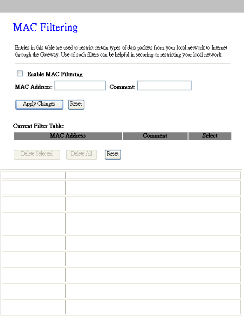
MAC Filtering
Enable MAC Filtering Check to enable MAC filtering function.
MAC Address Enter the client MAC address in the field.
Comment You may key in a description MAC address.
Apply Changes After completing the settings on this page, click Apply Changes
button to save the settings.
Reset Click Reset button to restore to default values.
Current Filter Table Shows the current MAC filter information.
Delete Selected Click Delete Selected button to delete items which are selected.
Delete All Click Delete All button to delete all the items.
Reset Click Reset button to rest.
Chapter 4: Web Configuration
44
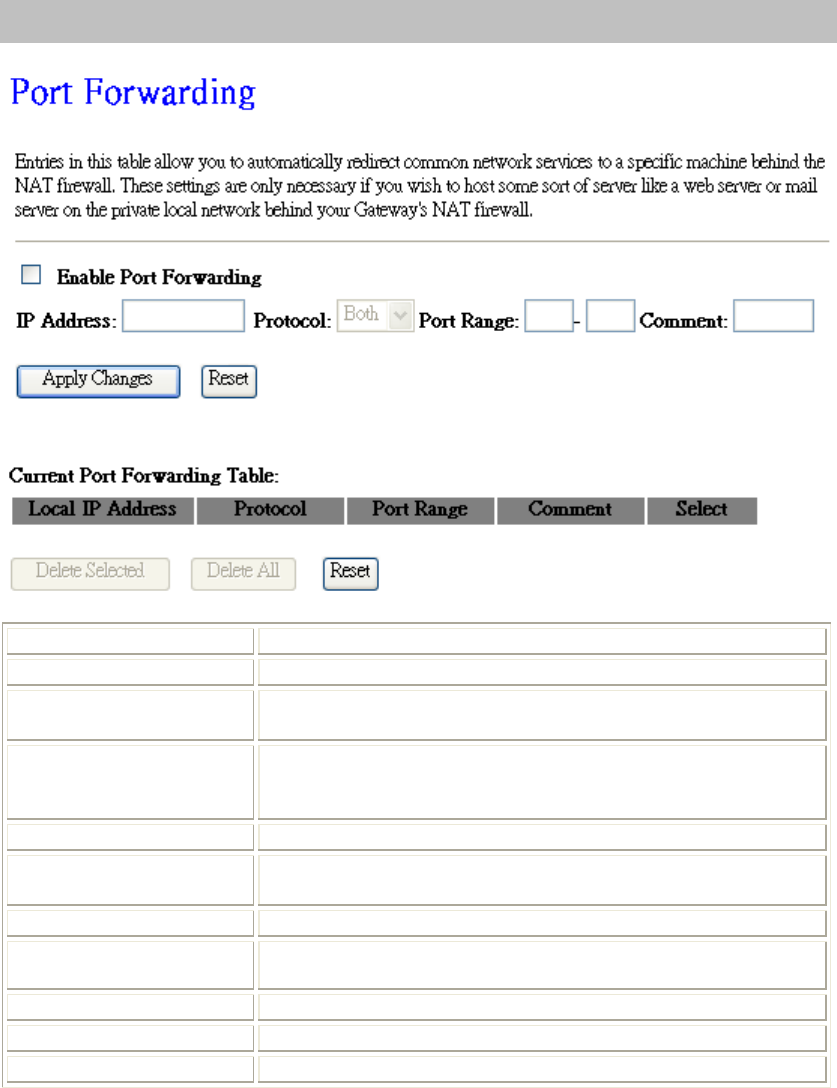
Port Forwarding
Enable Port Forwarding Check to enable Port Forwarding function.
IP Address Enter the IP address in the field.
Protocol Select the protocol (TCP, UDP or Both) used to the remote system
or service.
Port Range For TCP and UDP Services, enter the beginning of the range of
port numbers used by the service. If the service uses a single port
number, enter it in both the start and finish fields.
Comment You may key in a description MAC address.
Apply Changes After completing the settings on this page, click Apply Changes
button to save the settings.
Reset Click Reset button to restore to default values.
Current Port Forwarding
Table Shows the current Port Forwarding information.
Delete Selected Click Delete Selected button to delete items which are selected.
Delete All Click Delete All button to delete all the items.
Reset Click Reset button to rest.
Chapter 4: Web Configuration
45
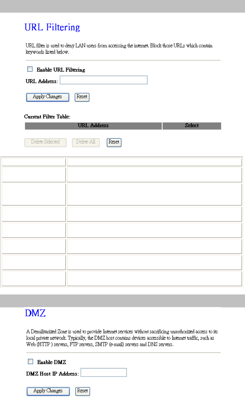
URL Filtering
Enable URL Filtering Check to enable URL filtering function.
URL Address Enter the URL address in the field.
Apply Changes After completing the settings on this page, click Apply Changes
button to save the settings.
Reset Click Reset button to restore to default values.
Current Filter Table Shows the current URL address filter information.
Delete Selected Click Delete Selected button to delete items which are selected.
Delete All Click Delete All button to delete all the items.
Reset Click Reset button to rest.
DMZ
Chapter 4: Web Configuration
46
Enable DMZ Check the box to enable DMZ function. If the DMZ Host Function is
enabled, it means that you set up DMZ host at a particular computer to
be exposed to the Internet so that some applications/software, especially
Internet / online game can have two way connections.
DMZ Host IP
Address Enter the IP address of a particular host in your LAN which will receive
all the packets originally going to the WAN port/Public IP address
above.
Note: You need to give your LAN PC clients a fixed/static IP address
for DMZ to work properly.
Apply Changes After completing the settings on this page, click Apply Changes button
to save the settings.
Reset Click Reset button to restore to default values.
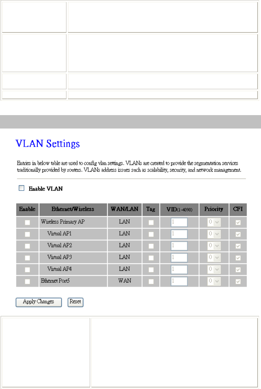
VLAN
Enable VLAN
VLAN(Virtual Local Area Network) refers to a group of
logically networked devices on one or more LANs that are
configured so that they can communicate as if they were
attached to the same wire, when in fact they are located on
different LAN segments. Because VLANs are based on logical
instead of physical connections, it is very flexible for user/host
management.
Enable this function to setup the virtual local area network.
Chapter 4: Web Configuration
47
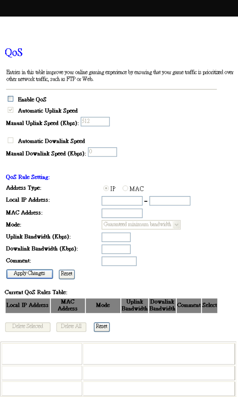
QoS
Use this section to configure QoS. The QoS settings improve your online gaming experience by
ensuring that your game traffic is prioritized over other network traffic, such as FTP or Web.
Enable QoS This function improves online gaming experience by ensuring
that game traffic is prioritized over other network traffic, such
as FTP or Web.
Automatic Uplink/Download
Speed Check the box to enable the automatic uplink/ download
speed function.
Manual Uplink/Download
Speed You can manually enter the uplink/ download transmission
rate in the blank field.
Chapter 4: Web Configuration
48
Address Type Select IP or MAC address type.
Local IP address
MAC address
Depend on the address type that selected, user can enter the IP
address or MAC address of client to set up the bandwidth of
the transmission.
Mode Select Guaranteed minimum bandwidth or Restricted
maximum bandwidth modes.
Uplink Bandwidth (Kbps) Enter the Uplink Bandwidth (Kbps) in the column.
Downlink Bandwidth (Kbps) Enter the Downlink Bandwidth (Kbps) in the column.
Comment Enter the note for the setting.
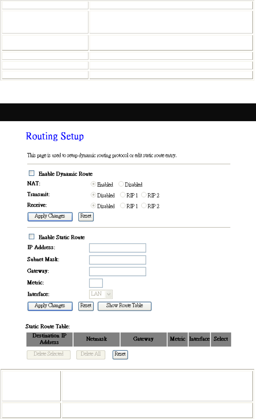
Route Setup
Enable Dynamic
Route Dynamic routing performs the same function as static routing except it is
more steady. Dynamic routing allows routing tables in routers to change
as the possible routes change. There are several protocols used to support
dynamic routing including RIP and OSPF.
NAT Network Address Translation (NAT) select to enable or disable this
function.
Chapter 4: Web Configuration
49
Transmit Select to enable or disable RIP protocol for transmit.
Receive Select to enable or disable RIP protocol for receive.
Enable Static
Route If you connect several routers with this Wireless Router, you may need to
set up a predefined routing rule to have more effective network
topology/traffic, this is called static route between those routers and the
Wireless Router.
To set static routers, enter the settings including route IP address, route
mask, route gateway and the route Interface from LAN or WAN.
IP Address Set up the IP address that would like to send the packets pass through.
Subnet Mask Set up the Subnet Mask that would like to send the packets pass through.
Gateway Set up the gateway that would like to send the packets pass through.
Metric It is used by a router to make routing decisions.
The metrics used by a router to make routing decisions. It is typically one
of many fields in a routing table. Router metrics can contain any number
of values that help the router determine the best route among multiple
routes to a destination. A router metric typically based on information like
path length, bandwidth, load, hop count, path cost, delay, Maximum
Transmission Unit (MTU), reliability and communications cost.
Interface Select the interface of the setting path.
Management
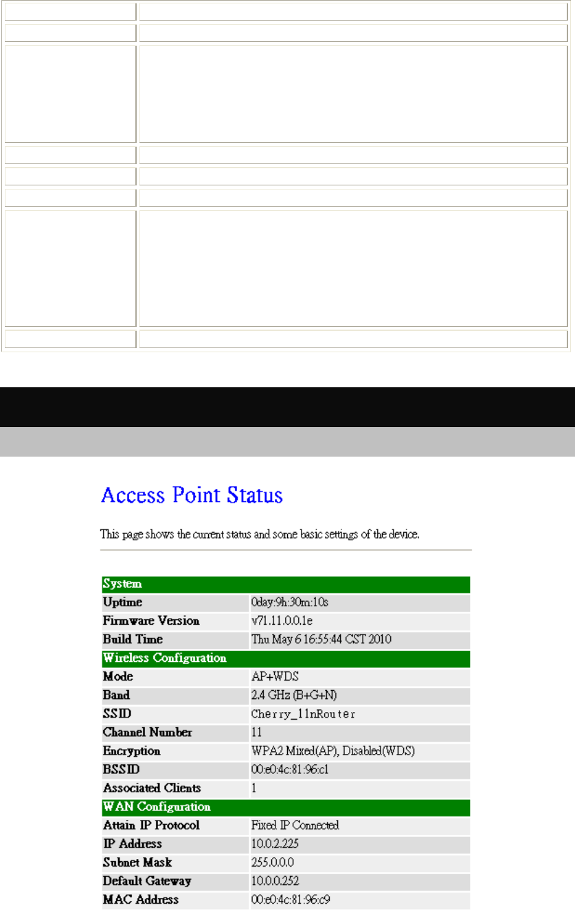
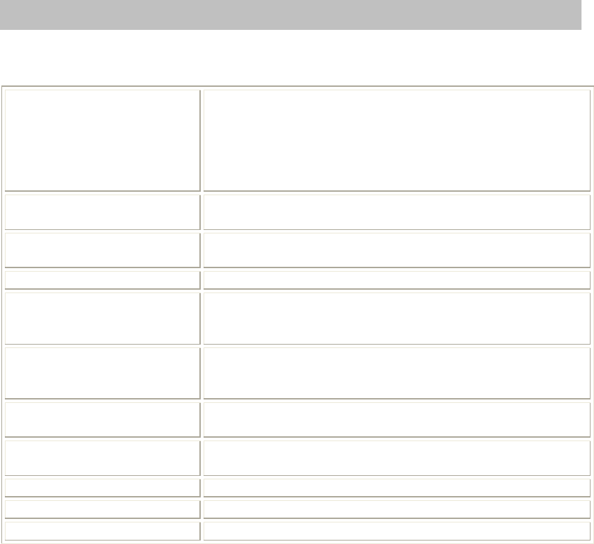
Status
This page shows the current Wireless Router settings information.
Chapter 4: Web Configuration
50
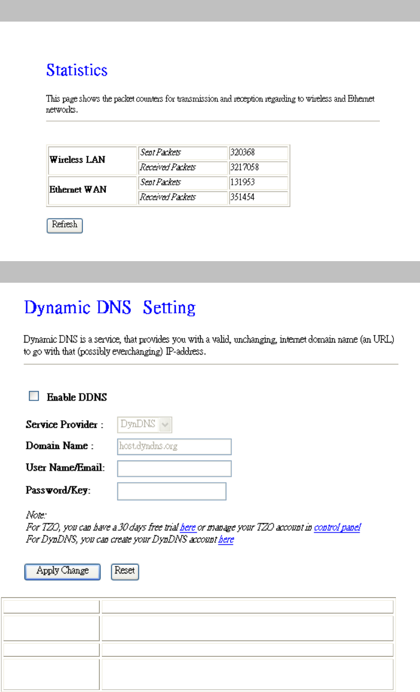
Statistics
This page shows the packet counters for transmission and reception regarding to wireless and Ethernet
networks.
Dynamic DNS
Enable DDNS Check to enable the DDNS function.
Service Provider Select the desired DDNS Service Provider DynDNS or TZO from
the pull-down list.
Domain Name Here shows the domain name of the service provider.
User Name/Email Enter your email that you registered in service provider website.
(
You can refer to
b
elow Note information to a
pp
l
y
a account form
Chapter 4: Web Configuration
51
the service provider website.)
Password/Key Enter your passwords that you registered in service provider website.
Maximum input is 30 alphanumeric characters (case sensitive).
Apply Changes After completing the settings on this page, click Apply Changes
button to save the settings.
Reset Click Reset button to restore to default values.
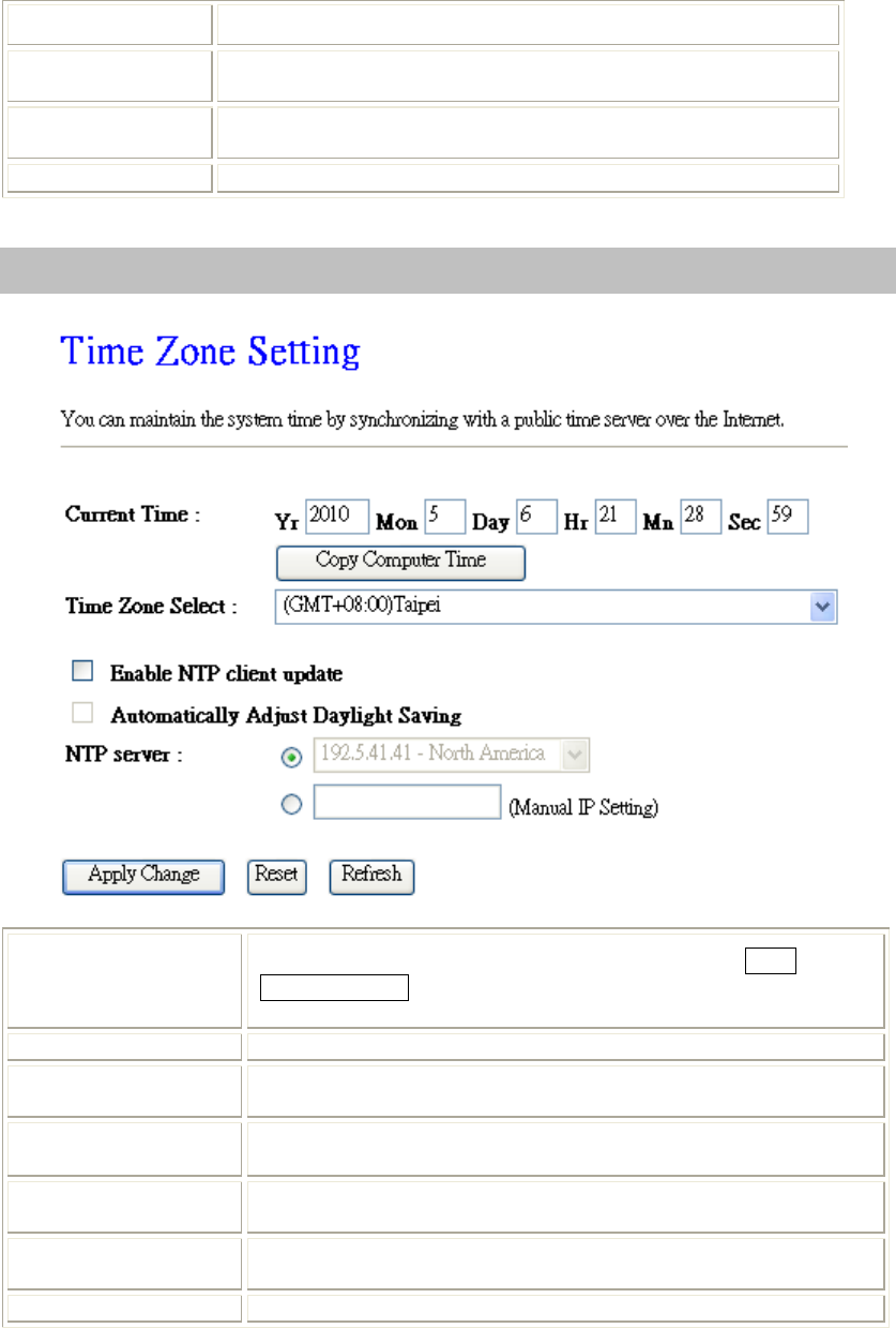
Time Zone Setting
Current Time Enter the current time of this wireless router or click the Copy
Computer Time button to synchronize the time with the connected
computer automatically.
Time Zone Select Select the local time zone from the pull-down menu.
Enable NTP client
update Check to enable NTP (Network Time Protocol Server) client update
function.
Automatically Adjust
Daylight Saving Check the box to enable this function.
NTP server
Manual IP Setting You may choose to select NTP server from the pull-down menu or
enter an IP address of a specific server manually.
Apply Changes After completing the settings on this page, click Apply Changes
button to save current settings.
Refresh Click Refresh button to renew current time.

Chapter 4: Web Configuration
52
Denial of Service
Enable DoS
Prevention DoS (Denial of Service) attacks can flood your Internet connection with
invalid packets and connection requests, using so much bandwidth and so
many resources that Internet access becomes unavailable. The Wireless
Router incorporates protection against DoS attacks. This screen allows you
to configure DoS protection.
Check the box to enable the DoS settings.
Chapter 4: Web Configuration
53
Select All After you enabled the DoS prevention, you can click to select all DoS
preventions.
Clear All After you enabled the DoS prevention, you can click to uncheck all DoS
preventions.
Apply Changes After completing the settings on this page, click Apply Changes button to
save current settings.
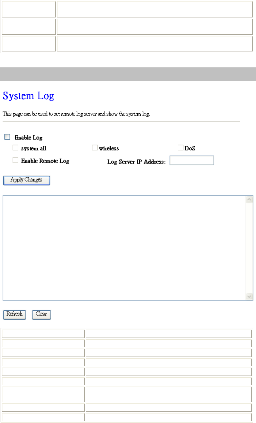
Logs
Enable Log Check to enable logging function.
System all Activates all logging functions.
Wireless Only logs related to the wireless LAN will be recorded.
DoS Only logs related to the DoS protection will be recorded.
Enable Remote Log Only logs related to the Remote control will be recorded.
Log Server IP address Only logs related to the server will be recorded.
Apply Changes After completing the settings on this page, click Apply
Changes button to save current settings.
Refresh Click Refresh button to renew the logs.
Clear Click Clear button to delete the logs.
Chapter 4: Web Configuration
54
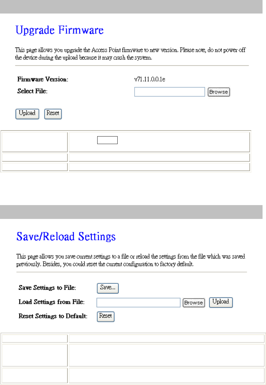
Upgrade Firmware
Select File Click the Browse button to find and open the firmware file (the
browser will display to correct file path.)
Upload Click the Upload button to perform.
Reset Click Reset button to restore to default values.
Save /Reload Settings
Save Settings to File Click the Save button to save the current settings file in the PC.
Load Settings form
File Click the Browse button to find and open the previous saved file (the
browser will display to correct file path.) Then, click Upload button to
upload the previous file.
Reset Settings to
Default Click Reset button to set the device back to default settings.
Chapter 4: Web Configuration
55
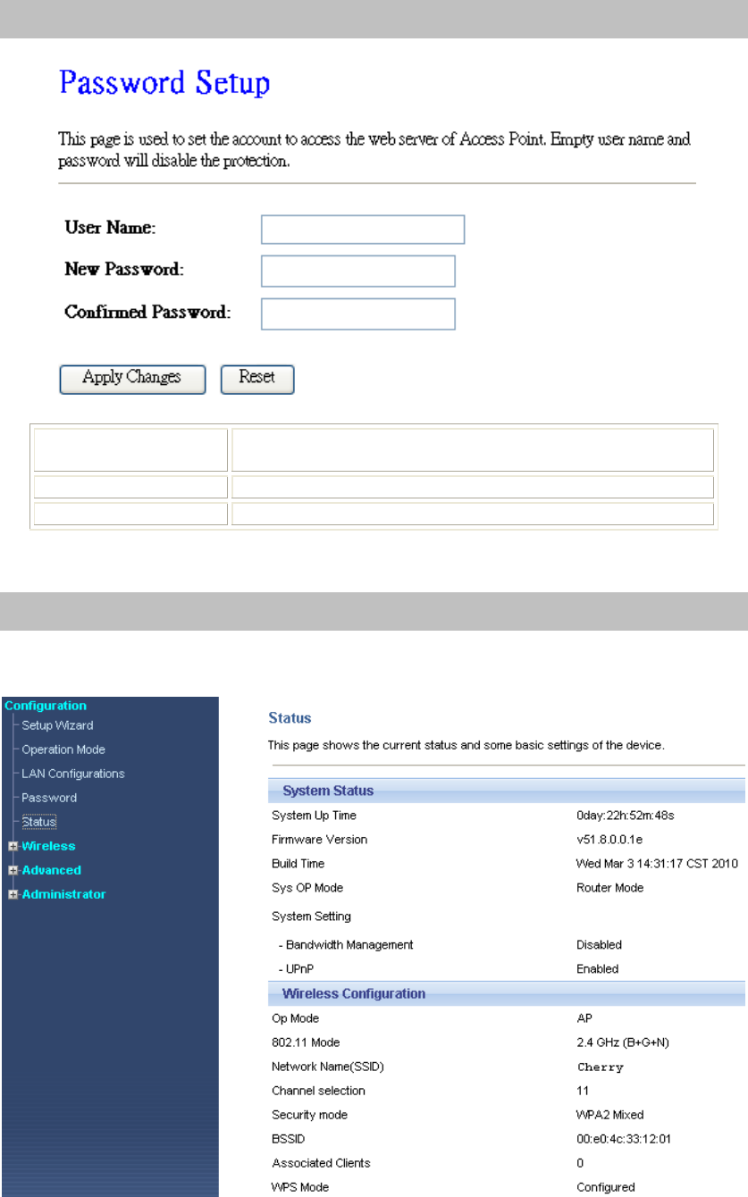
Password
User Name Key in a new login user name in the blank field. User can empty
the user name and password columns to disable the access.
New Password Maximum input is 30 alphanumeric characters (case sensitive.)
Confirmed Password Key in the password again to confirm.
Status
Chapter 4: Web Configuration
56
Bandwidth Mgmt
Enable Bandwidth
Management
Check the box to enable this function. If the DMZ Host Function
is enabled, it means that you set up DMZ host at a particular
computer to be exposed to the Internet so that some
applications/software, especially Internet / online game can have
two-way connections. You can select automatic or manual uplink
speed.
Automatic Uplink/Download
Speed Check the box to enable the automatic uplink/ download speed
function.
Manual Uplink/Download
Speed You can manually enter the uplink/ download transmission rate in
the blank field.
Address Type Select IP or MAC address type.
Local IP address
MAC address
Depend on the address type that selected, user can enter the IP
address or MAC address of client to set up the bandwidth of the
transmission.
Port Enter the beginning of port range numbers used by the service. If
the service uses a single port number, enter it in both the start and
finish fields.
Protocol Select the protocol (TCP, UDP, TCP/UDP, ICMP or ANY) used
to the remote system or service.
Mode Select Guaranteed minimum bandwidth or Restricted maximum
bandwidth modes.
Uplink Bandwidth (Kbps) Enter the Uplink Bandwidth (Kbps) in the column.
Downlink Bandwidth (Kbps) Enter the Downlink Bandwidth (Kbps) in the column.
Comment Enter the note for the setting.
Chapter 4: Web Configuration
57
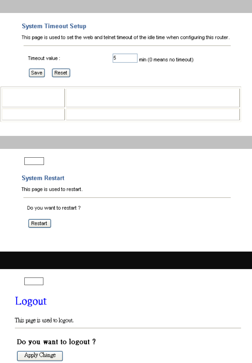
System Timeout Setup
Timeout value This page is used to set the web and telnet timeout of the idle
time when configuring this router.
Reset Click Reset button to restore to default values.
System Restart
Click the Restart button to restart the device.
Log out
Click the Logout button to leave the web configuration page.

Chapter 5: PC Configuration
58
Chapter 5: PC
Configuration
This Chapter details the PC
Configuration required on the
local ("Internal") LAN.
Overview
For each PC, the following may need to be configured:
• TCP/IP network settings
• Internet Access configuration
• Wireless configuration
Windows Clients
• This section describes how to configure Windows clients for Internet access via the Wireless
Router.
• The first step is to check the PC's TCP/IP settings.
• The Wireless Router uses the TCP/IP network protocol for all functions, so it is essential that the
TCP/IP protocol be installed and configured on each PC.
TCP/IP Settings - Overview
If using default Wireless Router settings, and default Windows TCP/IP settings, no changes need to be
made.
• By default, the Wireless Router will act as a DHCP Server, automatically providing a suitable IP
address (and related information) to each PC when the PC boots.
• For all non-Server versions of Windows, the default TCP/IP setting is to act as a DHCP client.
If using a Fixed (specified) IP address, the following changes are required:
• The Gateway must be set to the IP address of the Wireless Router.
• The DNS should be set to the address provided by your ISP.
Chapter 5: PC Configuration
59
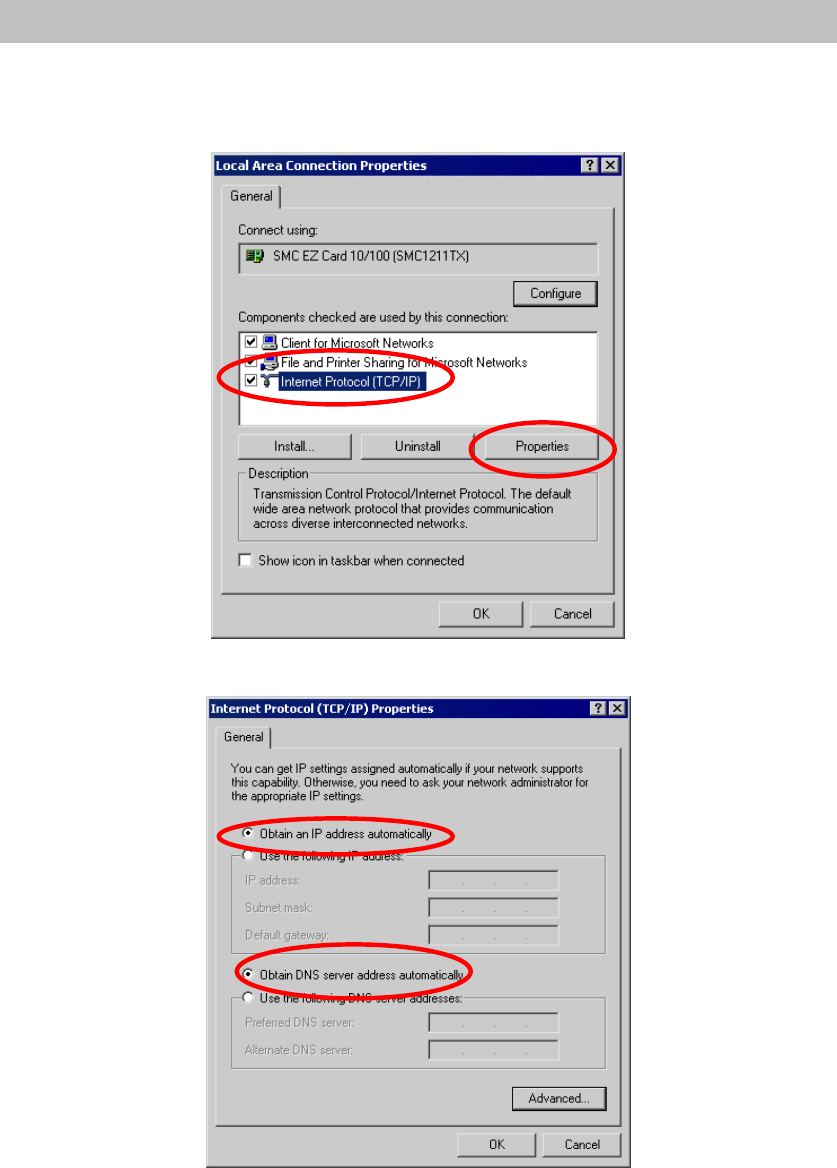
Checking TCP/IP Settings - Windows 2000
1. Select Control Panel - Network and Dial-up Connection.
2. Right - click the Local Area Connection icon and select Properties. You should see a screen like
the following:
3. Select the TCP/IP protocol for your network card.
4. Click on the Properties button. You should then see a screen like the following.
5. Ensure your TCP/IP settings are correct, as described below.
Using DHCP
• To use DHCP, select the radio button Obtain an IP Address automatically. This is the default
Windows setting. Using this is recommended. By default, the Wireless Router will act as a DHCP
Server.
• Restart your PC to ensure it obtains an IP Address from the Wireless Router.
Chapter 5: PC Configuration
60
Using a fixed IP Address ("Use the following IP Address")
If your PC is already configured, check with your network administrator before making the following
changes.
• Enter the Wireless Router 's IP address in the Default gateway field and click OK. (Your LAN
administrator can advise you of the IP Address they assigned to the Wireless Router.)
• If the DNS Server fields are empty, select Use the following DNS server addresses, and enters the
DNS address or addresses provided by your ISP, then click OK.
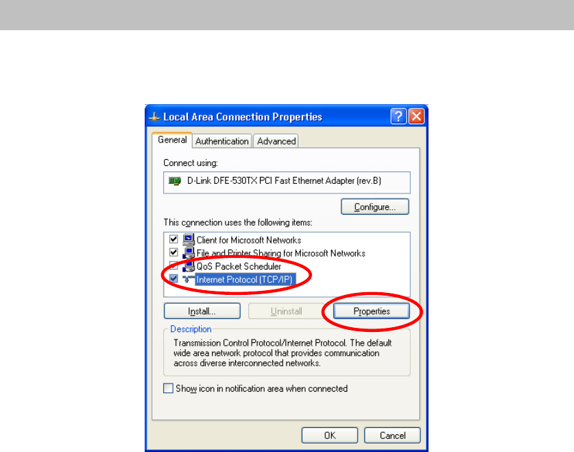
Checking TCP/IP Settings - Windows XP
1. Select Control Panel - Network Connection.
2. Right click the Local Area Connection and choose Properties. You should see a screen like the
following:
3. Select the TCP/IP protocol for your network card.
4. Click on the Properties button. You should then see a screen like the following.
Chapter 5: PC Configuration
61
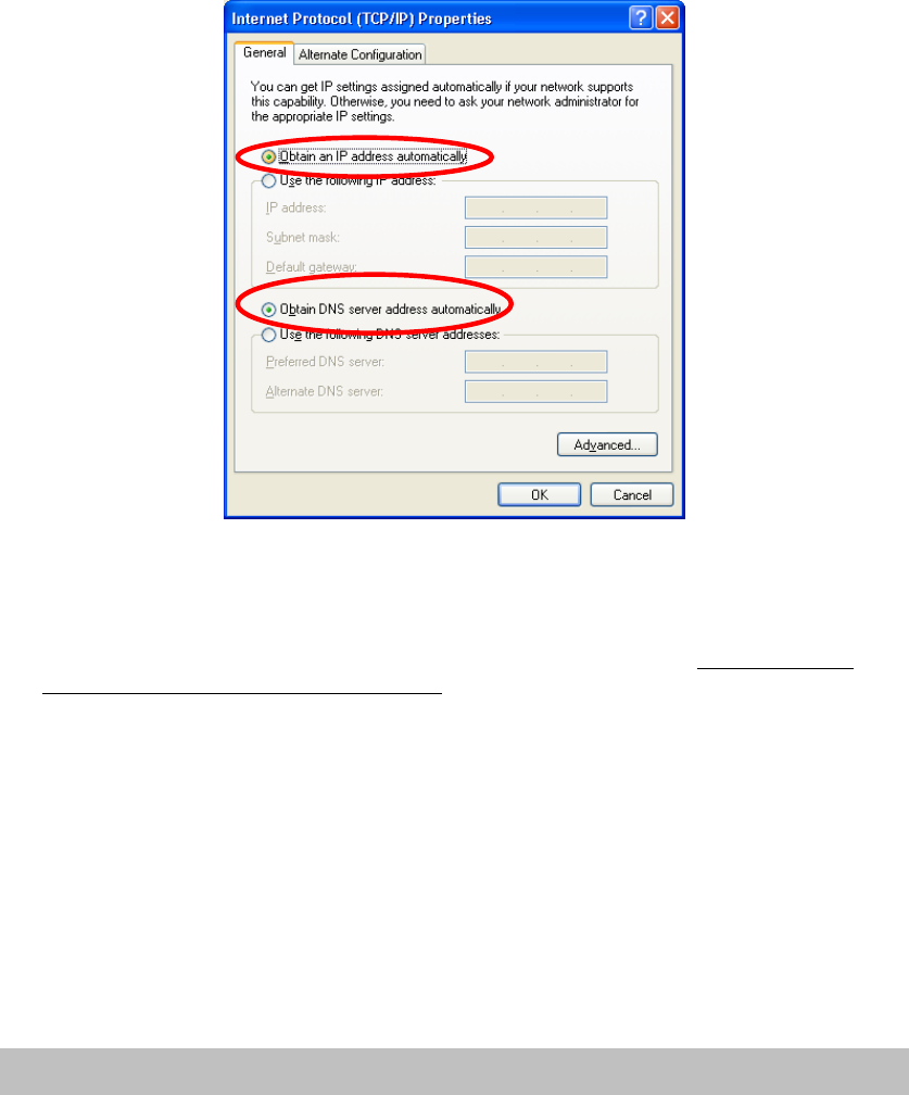
5. Ensure your TCP/IP settings are correct.
Using DHCP
• To use DHCP, select the radio button Obtain an IP Address automatically. This is the default
Windows setting. Using this is recommended. By default, the Wireless Router will act as a DHCP
Server.
• Restart your PC to ensure it obtains an IP address from the Wireless Router.
Using a fixed IP Address ("Use the following IP Address")
If your PC is already configured, check with your network administrator before making the following
changes.
• In the Default gateway field, enter the Wireless Router 's IP address and click OK. Your LAN
administrator can advise you of the IP Address they assigned to the Wireless Router.
• If the DNS Server fields are empty, select Use the following DNS server addresses, and enters the
DNS address or addresses provided by your ISP, then click OK.
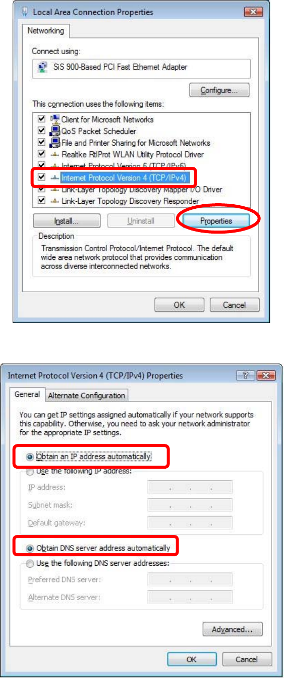
Checking TCP/IP Settings - Windows Vista
1. Go to Start > Control Panel> Network and Internet> Network and Sharing Center> Manage
Network Connections> Local Area Connection.
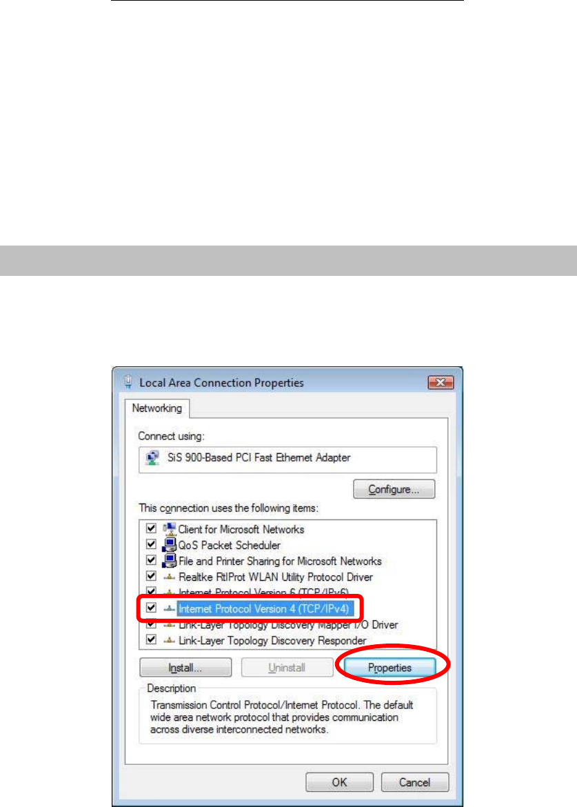
2. Right click the Local Area Connection icon and choose Properties. You should see a screen like
the following:
Chapter 5: PC Configuration
62
3. Select the Internet Protocol Version 4(TCP/IPv4) or 6 (TCP/IPv6) for your network card.
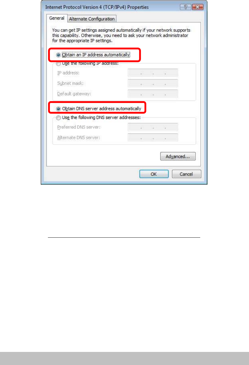
4. Click on the Properties button. You should then see a screen like the following.
5. Ensure your TCP/IP settings are correct.
Chapter 5: PC Configuration
63
Using DHCP
• To use DHCP, select Obtain an IP address automatically and Obtain DNS server address
automatically. This is the default Windows setting. Using this is recommended. By default, the
Wireless Router will act as a DHCP Server.
• Restart your PC to ensure it obtains an IP address from the Wireless Router.
Using a fixed IP Address ("Use the following IP Address")
If your PC is already configured, check with your network administrator before making the following
changes.
• In the Default gateway field, enter the Wireless Router 's IP address. Your LAN administrator can
advise you of the IP address they assigned to the Wireless Router.
• If the DNS Server fields are empty, select Use the following DNS server addresses, and enters the
DNS address or addresses provided by your ISP, then click OK.
Checking TCP/IP Settings - Windows 7
1. Go to Start > Control Panel> Network and Sharing Center> Manage Network Connections>
Local Area Connection.
2. Right click the Local Area Connection icon and choose Properties. You should see a screen like
the following:
3. Select the Internet Protocol Version 4(TCP/IPv4) or 6 (TCP/IPv6) for your network card.
4. Click on the Properties button. You should then see a screen like the following.
Chapter 5: PC Configuration
64
5. Ensure your TCP/IP settings are correct.
Using DHCP
• To use DHCP, select Obtain an IP address automatically and Obtain DNS server address
automatically. This is the default Windows setting. Using this is recommended. By default, the
Wireless Router will act as a DHCP Server.
• Restart your PC to ensure it obtains an IP address from the Wireless Router.
Using a fixed IP Address ("Use the following IP Address")
If your PC is already configured, check with your network administrator before making the following
changes.
• In the Default gateway field, enter the Wireless Router 's IP address. Your LAN administrator can
advise you of the IP address they assigned to the Wireless Router.
• If the DNS Server fields are empty, select Use the following DNS server addresses, and enters the
DNS address or addresses provided by your ISP, then click OK.
Internet Access
To configure your PCs to use the Wireless Router for Internet access:
• Ensure that the ADSL modem, DSL modem, Cable modem, or other permanent connection is
functional.
• Use the following procedure to configure your Browser to access the Internet via the LAN, rather
than by a Dial-up connection.

Chapter 5: PC Configuration
65
For Windows 2000
1. Select Start menu - Settings - Control Panel - Internet Options.
2. Select the Connection tab, and click the Setup button.
3. Select "I want to set up my Internet connection manually, or I want to connect through a local
area network (LAN)" and click Next.
4. Select "I connect through a local area network (LAN)" and click Next.
5. Ensure all of the boxes on the following Local area network Internet Configuration screen are
unchecked.
6. Check the "No" option when prompted "Do you want to set up an Internet mail account now?"
7. Click Finish to close the Internet Connection Wizard. Setup is now completed.
For Windows XP
1. Select Start menu >Control Panel > Network and Internet Connections.
2. Select Set up or change your Internet Connection.
3. Select the Connection tab, and click the Setup button.
4. Cancel the pop-up "Location Information" screen.
5. Click Next on the "New Connection Wizard" screen.
6. Select "Connect to the Internet" and click Next.
7. Select "Set up my connection manually" and click Next.
8. Check "Connect using a broadband connection that is always on" and click Next.
9. Click Finish to close the New Connection Wizard. Setup is now completed.
For Windows Vista
1. Select Start menu > Control Panel > Network and Internet> Network and Sharing Center.
2. Select Set up a connection or network.
3. Select Connect to the Internet and click Next to continue.
4. Select Broadband (PPPoE).
5. Enter User name and Password that provided by the ISP, then click Connect to make a connection.
For Windows 7
1. Select Start menu > Control Panel > Network Sharing Center.
2. Select Set up a new connection or network.
3. Select Connect to the Internet and click Next to continue.
4. Select Broadband (PPPoE).
5. Enter User name and Password that provided by the ISP, then click Connect to make a connection.

Chapter 5: PC Configuration
66
Accessing AOL
To access AOL (America On Line) through the Wireless Router, the AOL for Windows software must
be configured to use TCP/IP network access, rather than a dial-up connection. The configuration
process is as follows:
1. Start the AOL for Windows communication software. Ensure that it is Version 2.5, 3.0 or later.
This procedure will not work with earlier versions.
2. Click the Setup button.
3. Select Create Location, and change the location name from "New Locality" to " Wireless Router ".
4. Click Edit Location. Select TCP/IP for the Network field. (Leave the Phone Number blank.)
5. Click Save, then OK.
6. Configuration is now complete.
7. Before clicking "Sign On", always ensure that you are using the " Wireless Router " location.
Macintosh Clients
From your Macintosh, you can access the Internet via the Wireless Router. The procedure is as follows.
1. Open the TCP/IP Control Panel.
2. Select Ethernet from the Connect via pop-up menu.
3. Select Using DHCP Server from the Configure pop-up menu. The DHCP Client ID field can be
left blank.
4. Close the TCP/IP panel, saving your settings.
Note:
If using manually assigned IP addresses instead of DHCP, the required changes are:
• Set the Router Address field to the Wireless Router 's IP Address.
• Ensure your DNS settings are correct.
Linux Clients
To access the Internet via the Wireless Router, it is only necessary to set the Wireless Router as the
"Gateway".
Ensure you are logged in as "root" before attempting any changes.
Fixed IP Address
By default, most Unix installations use a fixed IP Address. If you wish to continue using a fixed IP
Address, make the following changes to your configuration.
• Set your "Default Gateway" to the IP Address of the Wireless Router.
• Ensure your DNS (Domain Name server) settings are correct.
To act as a DHCP Client (Recommended)
The procedure below may vary according to your version of Linux and X -windows shell.
1. Start your X Windows client.
2. Select Control Panel – Network.
3. Select the "Interface" entry for your Network card. Normally, this will be called "eth0".
4. Click the Edit button, set the "protocol" to "DHCP", and save this data.
5. To apply your changes:

Chapter 5: PC Configuration
67
• Use the "Deactivate" and "Activate" buttons, if available.
• OR, restart your system.
Other Unix Systems
To access the Internet via the Wireless Router:
• Ensure the "Gateway" field for your network card is set to the IP Address of the Wireless Router.
• Ensure your DNS (Name Server) settings are correct.
Wireless Station Configuration
• This section applies to all wireless stations wishing to use the Wireless Router 's access point,
regardless of the operating system that is used on the client.
• To use the Wireless Router, each wireless station must have compatible settings, as following:
Mode The mode must be set to Infrastructure.
SSID (ESSID) The network name must match the value used on the Wireless Router.
Note! The SSID is case- sensitive.
Disable If there is no security is enabled on the Wireless Router, the security of
each station should be disabled as well. And, you can connect the
Wireless Router without security, but it is NOT recommended.
WEP
By default, WEP on the Wireless Router is disabled.
• If WEP remains disabled on the Wireless Router, all stations must
have WEP disabled.
• If WEP is enabled on the Wireless Router, each station must use the
same settings as the Wireless Router.
WPA
WPA2
WPA-Mixed
802.1x
RADIUS Server: RADIUS is an authentication, authorization and
accounting client-server protocol. The client is a Network Access Server
that desires to authenticate its links. The server is a server that has
access to a user database with authentication information. Each station
must set up the RADIUS Server’s IP address, port and passwords that
provided by your ISP.
Note:
By default, the Wireless Router will allow 802.11b, 802.11g and 802.11n
connections.

Appendix A: Troubleshooting
68
Appendix A:
Troubleshooting
Overview
This chapter covers some common problems that may be encountered while using the Wireless Router
and some possible solutions to them. If you follow the suggested steps and the Wireless Router still
does not function properly, contact your dealer for further advice.
General Problems
Problem 1: Can't connect to the Wireless Router to configure it.
Solution 1: Check the following:
• Check the Wireless Router is properly installed, LAN connections are OK, and
it is powered ON.
• Ensure that your PC and the Wireless Router are on the same network segment.
• If your PC is set to "Obtain an IP Address automatically" (DHCP client), please
restart it.
• If your PC uses a Fixed (Static) IP address, ensure that it is using an IP Address
within the range 192.168.1.1 to 192.168.1.253 and thus compatible with the
Wireless Router's default IP Address of 192.168.1.254.
Also, the Network Mask should be set to 255.255.255.0 to match the Wireless
Router.
In Windows, you can check these settings by using Control Panel-Network to
check the Properties for the TCP/IP protocol.
Internet Access
Problem 1: When I enter a URL or IP address I get a time out error.
Solution 1: A number of things could be causing this. Try the following troubleshooting steps.
• Check if other PCs work. If they do, ensure that your PCs IP settings are
correct. If using a Fixed (Static) IP Address, check the Network Mask, Default
gateway and DNS as well as the IP Address.
• If the PCs are configured correctly, but still not working, check the Wireless
Router. Ensure that it is connected and ON. Connect to it and check its settings.
(If you can't connect to it, check the LAN and power connections.)

Appendix A: Troubleshooting
69
• If the Wireless Router is configured correctly, check your Internet connection
(DSL/Cable modem etc) to see that it is working correctly.
Problem 2: Some applications do not run properly when using the Wireless Router.
Solution 2: The Wireless Router processes the data passing through it, so it is not transparent.
Use the Content Filter Settings feature to allow the use of Internet applications,
which do not function correctly.
If this does solve the problem you can use the DMZ function. This should work with
almost every application, but:
• It is a security risk, since the firewall is disabled.
• Only one (1) PC can use this feature.
Wireless Access
Problem 1: My PC can't locate the Wireless Router.
Solution 1: Check the following:
• Your PC is set to Infrastructure Mode. (Access Points are always in
Infrastructure Mode)
• The SSID on your PC and the Wireless Router are the same.
Remember that the SSID is case-sensitive. So, for example "Workgroup" does
NOT match "workgroup."
• Both your PC and the Wireless Router must have the same setting for security.
The default setting for the Wireless Router security is disabled, so your wireless
station should also have security disabled.
• If security is enabled on the Wireless Router, your PC must have security
enabled, and the key must be matched.
• To see if radio interference is causing a problem, see if connection is possible
when close to the Wireless Router.
Remember that the connection range can be as little as 100 feet in poor
environments.
Problem 2: Wireless connection speed is very slow.
Solution 2: The wireless system will connect at the highest possible speed, depending on the
distance and the environment. To obtain the highest possible connection speed, you
can experiment with the following:
• Wireless Router location
Try adjusting the location and orientation of the Wireless Router.
• Wireless Channel
If interference is the problem, changing to another channel may show a marked
improvement.
• Radio Interference
Other devices may be causing interference. You can experiment by switching
other devices off, and see if this helps. Any "noisy" devices should be shielded
or relocated.

Appendix A: Troubleshooting
70
• RF Shielding
Your environment may tend to block transmission between the wireless
stations. This will mean high access speed is only possible when close to the
Wireless Router.

Appendix B: About Wireless LANs
71
Appendix B: About
Wireless LANs
BSS/ESS
BSS
A group of Wireless Stations and a single Access Point, all using the same ID (SSID), form a Basic
Service Set (BSS).
Using the same SSID is essential. Devices with different SSIDs are unable to communicate with each
other.
ESS
A group of Wireless Stations, and
multiple Access Points, all using the
same ID (ESSID), form an Extended
Service Set (ESS).
Different Access Points within an ESS
can use different Channels. In fact, to
reduce interference, it is
recommended that adjacent Access
Points SHOULD use different channels.
As Wireless Stations are physically
moved through the area covered by an
ESS, they will automatically change to
the Access Point which has the least

Appendix B: About Wireless LANs
72
interference or best performance. This
capability is called Roaming. (Access
Points do not have or require Roaming
capabilities.)
Channels
The Wireless Channel sets the radio frequency used for communication.
• Access Points use a fixed Channel. You can select the Channel used. This allows you to choose a
Channel which provides the least interference and best performance. In the USA and Canada, 11
channel are available. If using multiple Access Points, it is better if adjacent Access Points use
different Channels to reduce interference.
• In "Infrastructure" mode, Wireless Stations normally scan all Channels, looking for an Access
Point. If more than one Access Point can be used, the one with the strongest signal is used. (This
can only happen within an ESS.)
Note to US model owner:
To comply with US FCC regulation, the country selection function has been completely
removed from all US models. The above function is for non-US models only.
Security
WEP
WEP (Wired Equivalent Privacy) is a standard for encrypting data before it is transmitted. This is
desirable because it is impossible to prevent snoopers from receiving any data which is transmitted by
your Wireless Stations. But if the data is encrypted, then it is meaningless unless the receiver can
decrypt it.
If WEP is used, the Wireless Stations and the Access Point must have the same security settings
for each of the following:
WEP 64 Bits, 128 Bits.
Key For 64 Bits encryption, the Key value must match.
For 128 Bits encryption, the Key value must match.
WEP Authentication Open System or Shared Key.
WPA/WPA2/ WPA-Mixed
WPA/WPA2 (Wi-Fi Protected Access) is more secure than WEP. It uses a “Shared Key” which allows
the encryption keys to be regenerated at a specified interval. There are several encryption options:
TKIP, AES, TKIP-AES and additional setup for RADIUS is required in this method. The most
important features beyond WPA to become standardized through 802.11i/WPA2 are: pre-
authentication, which enables secure fast roaming without noticeable signal latency.
If WPA or WPA2 is used, the Wireless Stations and the Access Point must have the same security
settings.

Appendix B: About Wireless LANs
73
802.1x
With 802.1x authentication, a wireless PC can join any network and receive any messages that are not
encrypted, however, additional setup for RADIUS to issue the WEP key dynamically will be required.
RADIUS is an authentication, authorization, and accounting client-server protocol. The client is a
Network Access Server that desires to authenticate its links. The server is a server that has access to a
user database with authentication information.
If using "Ad-hoc" mode (no Access
Point), all Wireless stations should be
set to use the same Channel.
However, most Wireless stations will
still scan all Channels to see if there
is an existing "Ad-hoc" group they
can join.
Wireless LAN Configuration
To allow Wireless Stations to use the Access Point, the Wireless Stations and the Access Point must
use the same settings, as follows:
Mode The mode must be set to Infrastructure.
SSID (ESSID) The network name must match the value used on the Wireless Router.
Note! The SSID is case- sensitive.
Disable If there is no security is enabled on the Wireless Router, the security of
each station should be disabled as well. And, you can connect the
Wireless Router without security, but it is NOT recommended.
WEP
Open System/ Shared
Key/ Auto
By default, WEP on the Wireless Router is disabled.
Shared Key only supports WEP as encryption method.
AUTO(Open/Shared) means AP can accept STA connect to it using
OPEN-WEP or SHARED-WEP.
• If WEP remains disabled on the Wireless Router, all stations must
have WEP disabled.
• If WEP is enabled on the Wireless Router, each station must use the
same settings as the Wireless Router.
Personal (Pre-Shared
Key)
WPA
WPA2
WPA2-Mixed
WPA-PSK (TKIP/AES)/ WPA2-PSK (TKIP/AES: If one of these
securities is enabled on the Wireless Router. To make a connection,
each station must use the same algorithms and pass phrase as the
Wireless Router.
Pre-Shared Ke
y
Format: There are two formats for choice to set the

Appendix B: About Wireless LANs
74
Pre-shared key, Passphrase and Hex (64 characters). If Hex is
selected, users will have to enter a 64 characters string. For easier
configuration, the Passphrase (at least 8 characters) format is
recommended.
Pre-Shared Key : Pre-Shared Key serves as a password. Users may
key in 8 to 63 characters string if you selected passphrase. Pre-shared
key format to set the passwords or leave it blank, in which the 802.1x
Authentication will be activated. Make sure the same password is used
on client's end.
Enterprise (RADIUS)
WPA
WPA2
WPA2-Mixed
802.1x
RADIUS Server: RADIUS is an authentication, authorization and
accounting client-server protocol. The client is a Network Access Server
that desires to authenticate its links. The server is a server that has
access to a user database with authentication information. Each station
must set up the RADIUS Server’s IP address, port and passwords that
provided by your ISP.