Abocom Systems WG2100 802.11b/g MII Module User Manual WG2100 manual OK
Abocom Systems Inc 802.11b/g MII Module WG2100 manual OK
User manual
802.11 b/g MII Module
User’s Manual
REGULATORY STATEMENTS
FCC Certification
The United States Federal Communication Commission (FCC) and the Canadian
Department of Communications have established certain rules governing the use
of electronic equipment.
Part15, Class B
This device complies with Part 15 of FCC rules. Operation is subject to the
following two conditions:
1) This device may not cause harmful interference, and
2) This device must accept any interference received, including interference that
may cause undesired operation. This equipment has been tested and found to
comply with the limits for a Class B digital device, pursuant to Part 15 of the
FCC Rules. These limits are designed to provide reasonable protection against
harmful interference in a residential installation. This equipment generates and
can radiate radio frequency energy, and if not installed and used in accordance
with the instructions, may cause harmful interference to radio communications.
However, there is no guarantee that interference will not occur in a particular
installation. If this equipment does cause harmful interference to radio or
television reception, which can be determined by turning off and on, the user is
encouraged to try to correct the interference by one or more of the following
measures:
• Reorient or relocate the receiving antenna.
• Increase the separation between the equipment and receiver.
• Connect the equipment into an outlet on a circuit different from that to
which the receiver is connected.
• Consult the dealer or an experienced radio/TV technician for help.

Warning: Changes or modifications to this unit not expressly approved by
the party responsible for compliance could void the user authority to operate
the equipment.
CAUTION
1. To comply with FCC RF exposure compliance requirements, a separation
distance of at least 20 cm must be maintained between the antenna of this
device and all persons.
2. This Transmitter must not be co-located or operating in conjunction with any
other antenna or transmitter.
3. For product available in the USA market, only channel 1~11 can be operated.
Selection of other channels is not possible.
Table of Contents
INTRODUCTION...................................................................................................1
WIRELESS NETWORK OPTIONS ...............................................................................1
The Peer-to-Peer Network .........................................................................1
The Access Point Network ........................................................................2
INSTALLATION ....................................................................................................3
HARDWARE INSTALLATION.....................................................................................3
SOFTWARE INSTALLATION......................................................................................3
Device Installation Verification.................................................................5
CONFIGURATION ................................................................................................6
ACCESSING THE CONFIGURATION UTILITY..............................................................7
EASY CONFIG.........................................................................................................7
MAIN TAB............................................................................................................11
PROFILE TAB........................................................................................................13
ADVANCED TAB ...................................................................................................19
INFO TAB .............................................................................................................20
ABOUT TAB..........................................................................................................21
UNINSTALLATION.............................................................................................22
- 1 -
INTRODUCTION
The 802.11b/g MII Module is a device that allows you connect your
computer to a wireless local area network (LAN). A wireless LAN allows
your system to use wireless Radio Frequency (RF) technology to transmit
and receive data without physically attaching to the network. The wireless
protocols that come with this product ensure data security and isolation
from interference generated by other radio frequencies.
This card also allows you to take full advantage of your computer
’
s
mobility with access to real-time information and online services anytime
and anywhere. In addition, this device eliminates the bother of pulling
cable through walls and under furniture. It even allows you to place your
system in locations where cabling is impossible. Modifying and
augmenting networks has never been so easy.
Wireless Network Options
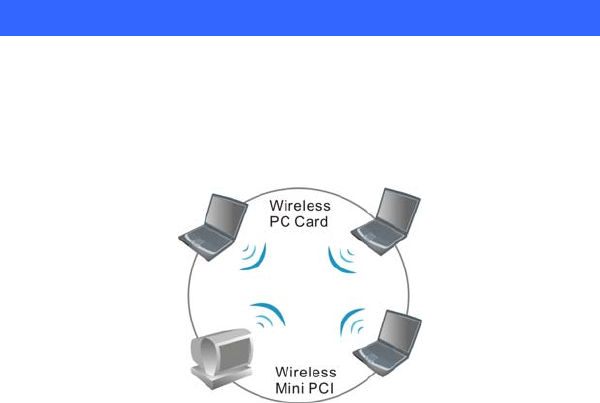
The Peer-to-Peer Network
This network installation lets you set a small wireless workgroup easily
and quickly. Equipped with wireless PC Cards or wireless Mini PCI, you
can share files and printers between each PC and laptop.
- 2 -
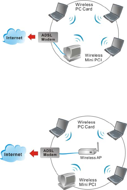
You can also use one computer as an Internet Server to connect to a wired
global network and share files and information with other computers via a
wireless LAN.
The Access Point Network
The network installation allows you to share files, printers, and Internet
access much more conveniently. With Wireless LAN Cards, you can
connect wireless LAN to a wired global network via an Access Point.

- 3 -
INSTALLATION
Hardware Installation
1. Make sure the computer is turned off. Remove the expansion slot
cover from the computer.
2. Carefully slide the MII Module into the Mini PCI slot. Push evenly
and slowly and ensure it is properly seated.
3. After the device has been connected to your computer, turn on your
computer. Windows will detect the new hardware and then
automatically copy all of the files needed for networking.
Software Installation
1. Exit all Windows programs. Insert the CD-ROM into the CD-ROM
drive of your computer.
If the CD-ROM is not launched automatically, go to your CD-ROM
drive (e.g. drive D) and double-click on Setup.exe.
2. The main screen of the CD-ROM opens. Click Install Driver &
Utility to start the installation.
- 4 -
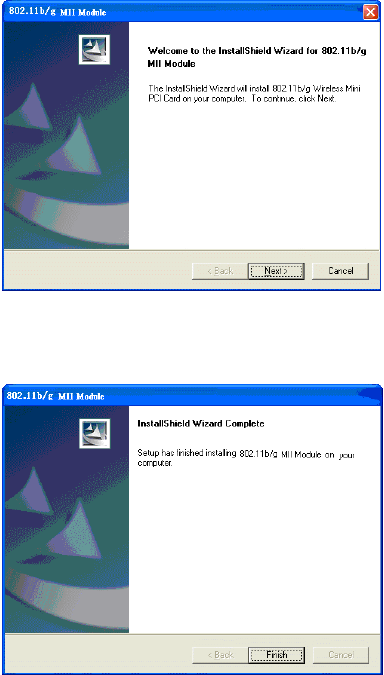
3. When the Welcome screen appears, click Next to continue.
4. Click Finish to complete the software installation.
- 5 -
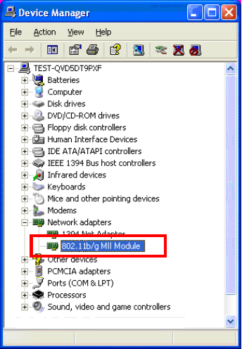
Device Installation Verification
To verify that the device has been properly installed in your computer and
is enabled, go to Start Settings Control Panel System (
Hardware) Device Manager. Expand the Network adapters item. If
the 802.11b/g MII Module is listed, it means that your device is properly
installed and enabled.
- 6 -
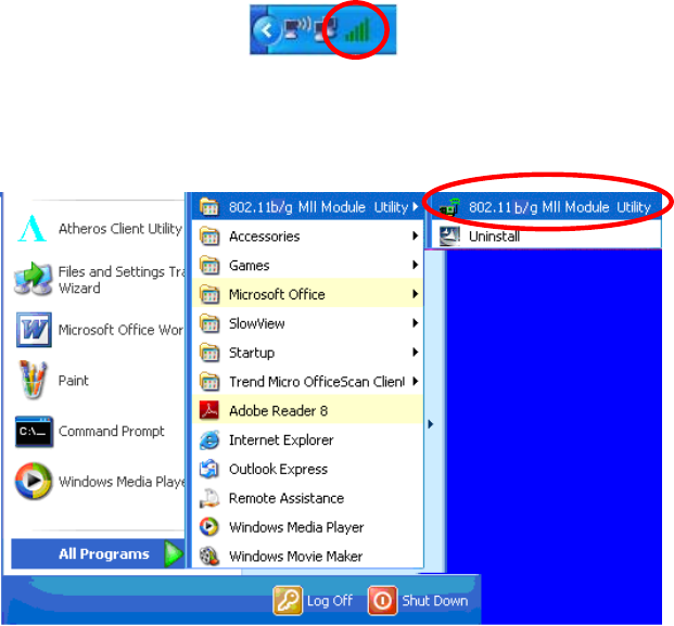
CONFIGURATION
After successful installation of the module
’
s driver, the utility icon will
display in the task bar. You will be able to access the Configuration
Utility through the Network Status icon.
If the icon doesn
’
t appear automatically, go to Start Programs
802.11 b/g MII Module Utility 802.11 b/g MII Module Utility, it
will appear in the task bar.
- 7 -
Accessing the Configuration Utility
All settings are categorized into 5 Tabs:
Main Tab
Profile Manager Tab
Advanced Tab
Info Tab
About Tab
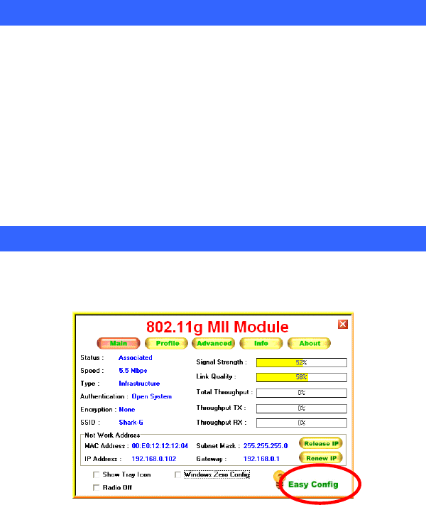
Easy Config
1. In the Main tab, click Easy Config on the right down corner to start a
quick configuration.
- 8 -
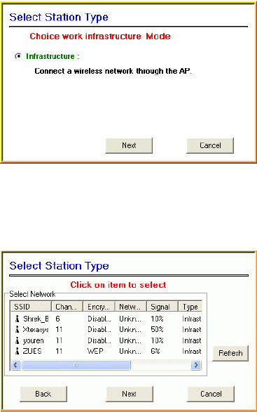
2. Select the wireless connection type- Infrastructure. Then click Next
to continue.
3. Select a wireless station on the list, and click Next to configure its
settings.
- 9 -
The following screen will appear for you to configure, for detailed
configuration, please refer to Profile tab in the later selection.
4. Configure the network TCP/IP, you may select DHCP to obtain an IP
address automatically or select Manual to set an IP address. Click
Next to continue.
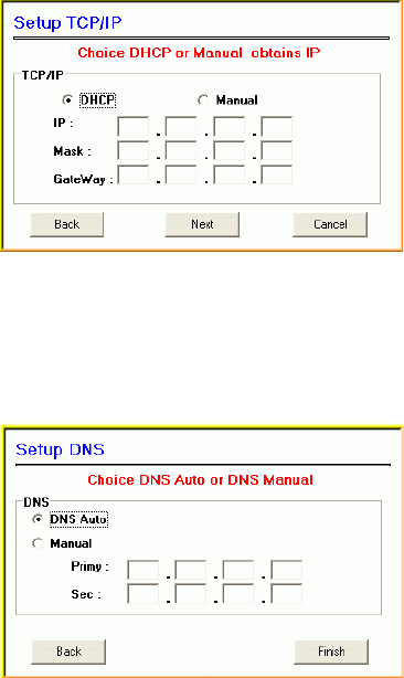
- 10 -
5. Select DNS Auto to obtain DNS automatically or select Manual to
set the primary and secondary DNS. Click Finish to complete the
Easy Config procedure.
- 11 -
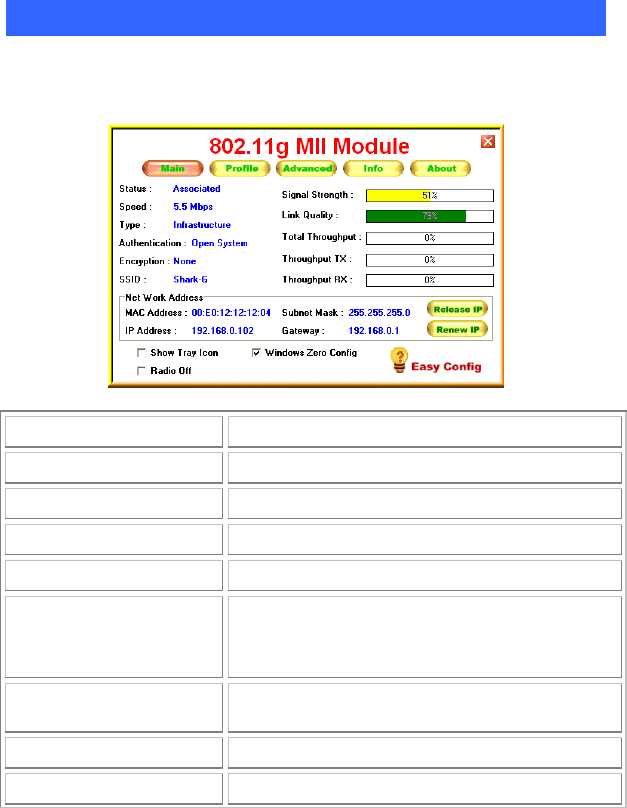
Main Tab
The main tab enables you to scan for available networks, select a network
to which to connect, modify the settings for the current connection.
Status Shows the current connection status.
Speed Shows the connection speed.
Type Shows the wireless connection type.
Authentication Shows the authentication type.
Encryption Shows the encryption type.
SSID The SSID is the unique name shared among all
points in your wireless network. The name must be
identical for all devices and points attempting to
connect to the same network.
Signal Strength The signal strength from the network Access Point or
station.
Link Quality Shows the link quality percentage.
Total Throughput Shows the total throughput percentage.

- 12 -
Throughput TX The actual instantaneous transmitting rates.
Throughput RX The actual instantaneous receiving rates.
Network Address
MAC Address The MAC address of this wireless adapter.
IP Address The IP address of this wireless adapter.
Subnet Mask The subnet mask of this wireless adapter.
Gateway The default gateway address of the adapter.
□
Show Tray icon Place a check in the check box to show the utility
icon in the tray.
□
Radio Off Place a check in the check box to disable the radio
function.
□
Windows Zero Config External Configuration Checkbox (Windows XP
only): A checkbox that enables you to disable the
WLAN Station Configuration Utility and indicates
that the station driver is to be configured with
Windows XP
痴
built-in Zero Configuration Utility
(ZCU).
On Windows XP systems, the ZCU service is
automatically stopped when the WLAN utility is
installed. The ZCU is started when you check the
Configure using Windows Zero Configuration
checkbox.
The checkbox is only displayed on Windows XP
systems.
- 13 -
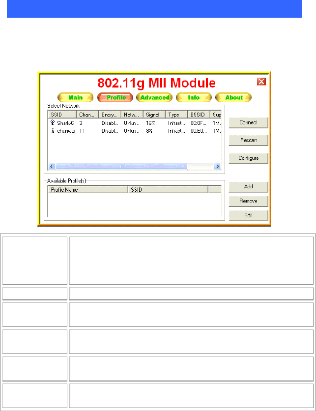
Profile Tab
The Profile tab enables you to connect, rescan, configuration, add,
remove and edit the profiles that the station uses to connect to WLAN
networks.
Connect Select a wireless device that you want to connect with and click
Connect button to make a connection. The wireless device you
have connected will be added into the Available Profile(s) field
below.
Rescan Click Rescan button to refresh the wireless device list.
Configure Click Configure to set up the detailed configuration.
Add Click Add to add a wireless device into the Available Profile(s)
field below.
Remove Select a wireless device that listed in the Available Profile(s)
field and then click Remove to delete it.
Edit Select a wireless device in the Available Profile(s) field and
then click Edit to change its configuration.
- 14 -
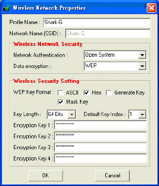
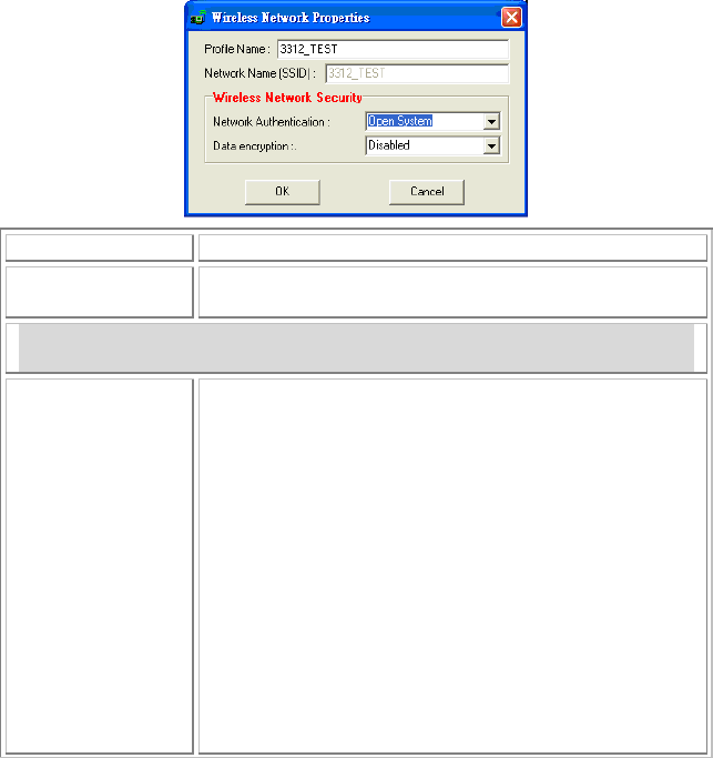
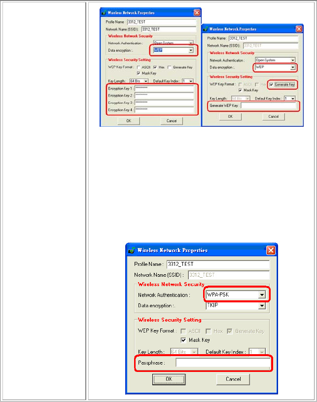
Wireless Network Properties
The Wireless Network Properties screen will appear if you just click
Connect, Configure or Add buttons.
Profile Name You may enter the preferred profile name in this column.
Network Name
(SSID) The SSID for the current profile.
Wireless Network Security
Network
Authentication The authentication type defines configuration options for
the sharing of wireless networks to verify identity and
access privileges of roaming wireless network cards.
Select the Network Authentication from the pull-down list.
Open System: If the Access Point is using "Open System"
authentication, then the wireless adapter will need to be set
to the same authentication type.
Shared Key: Shared Key is when both the sender and the
recipient share a secret key.
If WEP is selected from Data encryption pull-down
menu, you can either input Encryption Key 1~4 or
check the Generate Key box and enter WEP keys in
the Generate WEP Key blank, then the system will
generate keys automatically.
- 15 -
WPA-PSK/WPA2-PSK: In the Passphrase field,
enter the key (8~63 characters, case sensitive.) that
you are sharing with the network for the WLAN
connection. By default, the key that you type is
masked with asterisks (*). To view the key that you
entered, uncheck the Mask Key box.
If WPA-PSK/WPA2-PSK is selected from Data
encryption pull-down menu, enter the Passphrase in the
column to setup the wireless network security.

- 16 -
Data encryption Select the data encryption from the pull-down menu, either
TKIP or AES.
WEP Key Format ASCII (American Standard Code for Information
Interchange), the standard for assigning numerical
values to the set of letters in the Roman alphabet and
typographic characters.
HEX (Hexadecimal): numbers from 0 to 9 and letters
from A to F.
Generate Key: Check the Generate Key box and
enter WEP keys in the Generate WEP Key blank,
then the system will generate keys automatically.
Mask Key: Place a check in the check box to enable
the Unmask Key function, this function is for
concealing the WEP key.
Key Length Select the key length from the pull-down menu, either 64
Bit or 128 Bit.
If you are using 64-bit WEP encryption, then the key must
consist of exactly 10 hexadecimal characters or 5 ASCII
characters. If you are using 128-bit WEP encryption, then
the key 26 hexadecimal characters or 13 ASCII characters.
Valid hexadecimal characters are “0” to “9” and
鄭
” to
擢
”.
Default Key Index Select the default key index 1~4 from the pull-down menu.
Passphrase Instead of manually entering WEP keys, you can enter a
Passphrase, so that a WEP key is automatically generated. It
is case-sensitive and should not be longer than 16
alphanumeric characters. This Passphrase must match the
Passphrase of your wireless network.
Encryption Key
1~4 To configure your WEP settings. WEP (Wired Equivalent
Privacy) encryption can be used to ensure the security of
y
our wireless network. Select one Ke
y
and Ke
y
Size then

- 17 -
fill in the appropriate value/phrase in Encryption field.
Note: You must use the same Key and Encryption settings
for the both sides of the wireless network to connect.
KEY 1 ~ KEY 4:You can specify up to 4 different keys to
decrypt wireless data. Select the Default key setting from
the radio button.
Encryption:This setting is the configuration key used in
accessing the wireless network via WEP encryption.
A key of 10 hexadecimal characters (0-9, A-F) is required if
a 64-bit Key Length was selected.
A key of 26 hexadecimal characters (0-9, A-F) is required if
a 128-bit Key Length was selected.
A key of 58 hexadecimal characters (0-9, A-F) is required if
a 256-bit Key Length was selected.
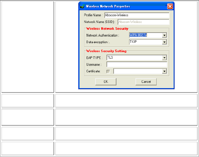
802.1x configure
EAP TYPE WPA 802.1x/ WPA2 802.1x: Require setting up a
RADIUS sever for authentication, RADIUS server manager
will assign the username and password.
Select the EAP TYPE from the pull-down list. Including
TLS, TTLS and PEAP.
- 18 -
Username Type in the user name assigned to the certificate.
Certificate Please query your network manager about the certificate,
select the same certificate as the certification server.
OK Click OK to save the configuration.
Cancel Click Cancel to exit the configuration screen.
- 19 -
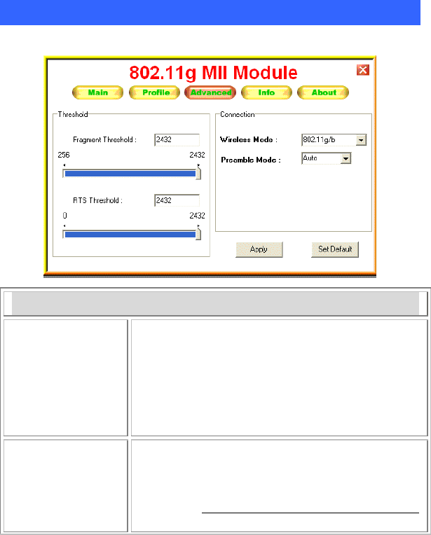
Advanced Tab
The Advanced tab displays the current status of the module.
Threshold
Fragment
Threshold The mechanism of Fragmentation Threshold is used to
improve the efficiency when high traffic flows along in
the wireless network. If your 802.11b/g Wireless LAN
Adapter often transmits large files in wireless network,
you can enter new Fragment Threshold value to split
the packet. The value can be set from 256 to 2432.
The default value is 2432.
RTS Threshold RTS/CTS Threshold is a mechanism implemented to
prevent the
“
Hidden Node
”
problem. If the
“
Hidden
Node
”
problem is an issue, users have to specify the
packet size. The RTS/CTS mechanism will be activated
i
f
the data size exceeds the value
y
ou set. The default

- 20 -
value is 2432.
This value should remain at its default setting of 2432.
Should you encounter inconsistent data flow, only
minor modifications of this value are recommended.
Connection Wireless Mode: Select 802.11b or 802.11g/b from the
pull-down menu.
Preamble Mode: A preamble is a signal used in
wireless environment to synchronize the transmitting
timing including Synchronization and Start frame
delimiter. Select from the pull-down menu to change
the Preamble type into Auto, Long or Short.
Apply Click to save current changes.
Set Default Click to restore default settings.
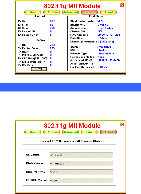
Info Tab
The Info tab displays information maintained by the driver, such as the
number of packet errors and the total number of bytes received or
transmitted. The tab also displays information about the current
connection, as well as network information about the station. The
statistics are for the period starting when you last connected to a
network. The statistics are refreshed at least twice a second.
- 21 -
About Tab
Click on the About tab to view basic version information about the OS
Version, Utility Version, Driver Version, Firmware Version and
EEPROM Version.
- 22 -
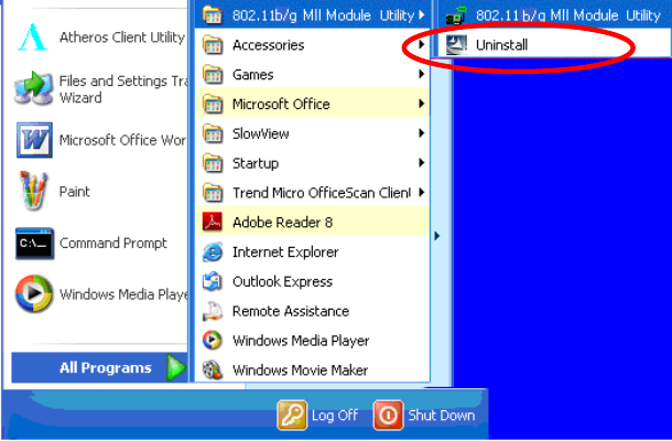
UNINSTALLATION
In case you need to uninstall the Utility and driver, please refer to below
steps. (As you uninstall the utility, the driver will be uninstalled as well.)
1. Go to Start (All) Programs 802.11b/g MII Module Utility
Uninstall.
- 23 -
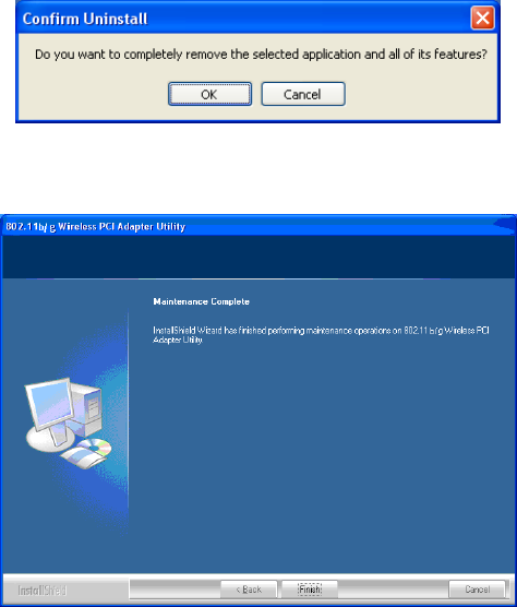
2. Click OK to complete remove the selected application and all of its
features.
3. Click Finish to complete the uninstalled procedure.
- 24 -
Federal Communication Commission Interference Statement
This equipment has been tested and found to comply with the limits for a
Class B digital device, pursuant to Part 15 of the FCC Rules. These limits are
designed to provide reasonable protection against harmful interference in a
residential installation. This equipment generates, uses and can radiate radio
frequency energy and, if not installed and used in accordance with the
instructions, may cause harmful interference to radio communications.
However, there is no guarantee that interference will not occur in a particular
installation. If this equipment does cause harmful interference to radio or
television reception, which can be determined by turning the equipment off
and on, the user is encouraged to try to correct the interference by one of the
following measures:
● Reorient or relocate the receiving antenna.
● Increase the separation between the equipment and receiver.
● Connect the equipment into an outlet on a circuit different from that to
which the receiver is connected.
● Consult the dealer or an experienced radio/TV technician for help.
FCC Caution: Any changes or modifications not expressly approved by the
party responsible for compliance could void the user's authority to operate
this equipment.
This device complies with Part 15 of the FCC Rules. Operation is subject to
the following two conditions: (1) This device may not cause harmful
interference, and (2) this device must accept any interference received,
including interference that may cause undesired operation.
Country Code Statement
For product available in the USA/Canada market, only channel 1~11 can be
operated. Selection of other channels is not possible.
This device and its antenna(s) must not be co-located or operation in
conjunction with any other antenna or transmitter.
IMPORTANT NOTE:
- 25 -
FCC Radiation Exposure Statement:
This equipment complies with FCC radiation exposure limits set forth for an
uncontrolled environment. This equipment should be installed and operated
with minimum distance 20cm between the radiator & your body.
IMPORTANT NOTE:
This module is intended for OEM integrator. The OEM integrator is still
responsible for the FCC compliance requirement of the end product, which
integrates this module.
20cm minimum distance has to be able to be maintained between the antenna
and the users for the host this module is integrated into. Under such
configuration, the FCC radiation exposure limits set forth for an
population/uncontrolled environment can be satisfied.
Any changes or modifications not expressly approved by the manufacturer
could void the user's authority to operate this equipment.
USERS MANUAL OF THE END PRODUCT:
In the users manual of the end product, the end user has to be informed to
keep at least 20cm separation with the antenna while this end product is
installed and operated. The end user has to be informed that the FCC
radio-frequency exposure guidelines for an uncontrolled environment can be
satisfied. The end user has to also be informed that any changes or
modifications not expressly approved by the manufacturer could void the
user's authority to operate this equipment. If the size of the end product is
smaller than 8x10cm, then additional FCC part 15.19 statement is required to
be available in the users manual: This device complies with Part 15 of FCC
rules. Operation is subject to the following two conditions: (1) this device
may not cause harmful interference and (2) this device must accept any
interference received, including interference that may cause undesired
operation.
LABEL OF THE END PRODUCT:
- 26 -
The final end product must be labeled in a visible area with the following "
Contains TX FCC ID: MQ4WG2100 ". If the size of the end product is
larger than 8x10cm, then the following FCC part 15.19 statement has to also
be available on the label: This device complies with Part 15 of FCC rules.
Operation is subject to the following two conditions: (1) this device may not
cause harmful interference and (2) this device must accept any interference
received, including interference that may cause undesired operation.