Abocom Systems WM5100 802.11n compliant 2.4GHz Mini-PCI Module User Manual WM5100 Eng Manual
Abocom Systems Inc 802.11n compliant 2.4GHz Mini-PCI Module WM5100 Eng Manual
UserManual.wiki
>
Abocom Systems
>
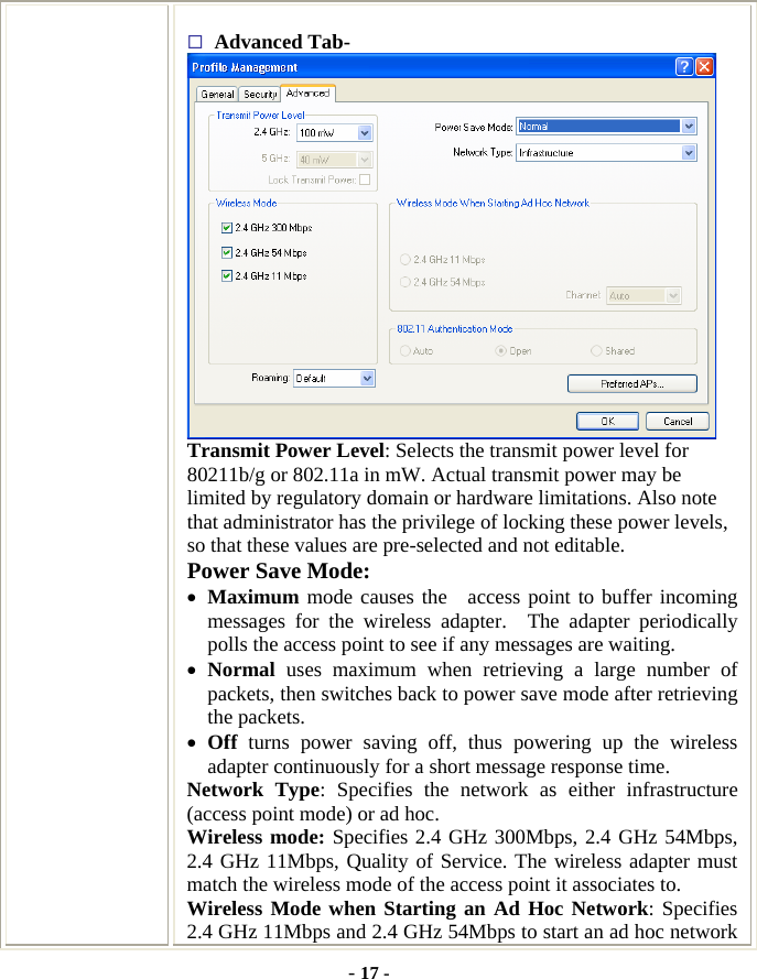
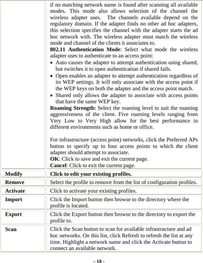
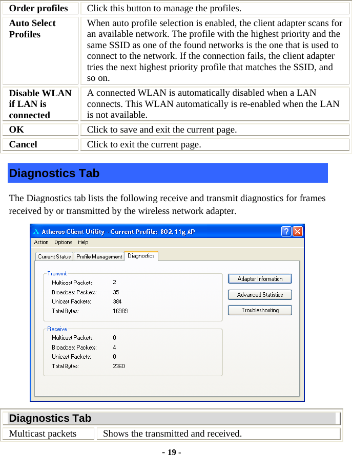
WM5100 User Manual
User Manual
Navigation menu
Upload a User Manual
Namespaces
Wiki Guide
HTML
PDF
Info
Views
User Manual
Discussion / Help
Navigation