Abocom Systems WM5100 802.11n compliant 2.4GHz Mini-PCI Module User Manual WM5100 Eng Manual
Abocom Systems Inc 802.11n compliant 2.4GHz Mini-PCI Module WM5100 Eng Manual
User Manual
802.11n compliant 2.4GHz
Mini-PCI Module
User’s Manual
REGULATORY STATEMENTS
FCC Certification
The United States Federal Communication Commission (FCC) and the
Canadian Department of Communications have established certain rules
governing the use of electronic equipment.
Part15, Class B
This device complies with Part 15 of FCC rules. Operation is subject to the
following two conditions:
1) This device may not cause harmful interference, and
2) This device must accept any interference received, including interference
that may cause undesired operation. This equipment has been tested and
found to comply with the limits for a Class B digital device, pursuant to Part
15 of the FCC Rules. These limits are designed to provide reasonable
protection against harmful interference in a residential installation. This
equipment generates, uses and can radiate radio frequency energy, and if not
installed and used in accordance with the instructions, may cause harmful
interference to radio communications. However, there is no guarantee that
interference will not occur in a particular installation. If this equipment does
cause harmful interference to radio or television reception, which can be
determined by turning off and on, the user is encouraged to try to correct the
interference by one or more of the following measures:
• Reorient or relocate the receiving antenna.
• Increase the separation between the equipment and receiver.
• Connect the equipment into an outlet on a circuit different from that
to which the receiver is connected.
• Consult the dealer or an experienced radio/TV technician for help.
IMPORTANT NOTE:
This module is intended for OEM integrator. The OEM integrator is still
responsible for the FCC compliance requirement of the end product, which
integrates this module. 20cm minimum distance has to be able to be maintained
between the antenna and the users for the host this module is integrated into.
Under such configuration, the FCC radiation exposure limits set forth for an
population/uncontrolled environment can be satisfied. Any changes or
modifications not expressly approved by the manufacturer could void the user's
authority to operate this equipment.
USERS MANUAL OF THE END PRODUCT:
In the users manual of the end product, the end user has to be informed to keep
at least 20cm separation with the antenna while this end product is installed and
operated. The end user has to be informed that the FCC radio-frequency
exposure guidelines for an uncontrolled environment can be satisfied. The end
user has to also be informed that any changes or modifications not expressly
approved by the manufacturer could void the user's authority to operate this
equipment. If the size of the end product is smaller than 8x10cm, then additional
FCC part 15.19 statement is required to be available in the users manual: This
device complies with Part 15 of FCC rules. Operation is subject to the following
two conditions: (1) this device may not cause harmful interference and (2) this
device must accept any interference received, including interference that may
cause undesired operation.
LABEL OF THE END PRODUCT:
The final end product must be labeled in a visible area with the following "
Contains TX FCC ID: MQ4WM5100 ". If the size of the end product is larger than
8x10cm, then the following FCC part 15.19 statement has to also be available on
the label: This device complies with Part 15 of FCC rules. Operation is subject to
the following two conditions: (1) this device may not cause harmful interference
and (2) this device must accept any interference received, including interference
that may cause undesired operation.

Warning: Changes or modifications to this unit not expressly approved by the
party responsible for compliance could void the user authority to operate the
equipment.
CAUTION
1. To comply with FCC RF exposure compliance requirements, a separation
distance of at least 20 cm must be maintained between the antenna of this
device and all persons.
2. This Transmitter must not be co-located or operating in conjunction with
any other antenna or transmitter.
3. For product available in the USA market, only channel 1~11 can be
operated. Selection of other channels is not possible.
Agency in the United States of America:
Company Name: Xterasys Corporation
Tel: 909-590-0600 Fax: 909-590-0388
Address: 4711 CHINO AVE. CHINO, CA91710 USA
Table of Contents
INTRODUCTION...................................................................................................1
WIRELESS NETWORK OPTIONS ...............................................................................1
The Peer-to-Peer Network .........................................................................1
The Access Point Network ........................................................................2
INSTALLATION ....................................................................................................3
INSTALL THE DEVICE ..............................................................................................3
INSTALL THE DRIVER & UTILITY ............................................................................3
Verify Device Installation........................................................................10
CONFIGURATION ..............................................................................................11
ACCESSING THE CONFIGURATION UTILITY............................................................11
CURRENT STATUS TAB .........................................................................................12
PROFILE MANAGER TAB.......................................................................................13
DIAGNOSTICS TAB................................................................................................19
ACTION ................................................................................................................20
OPTIONS...............................................................................................................21
HELP....................................................................................................................23
UNINSTALLATION.............................................................................................24
- 1 -
INTRODUCTION
The 802.11n compliant 2.4GHz Mini-PCI Module is a device that allows you
connect your computer to a wireless local area network (LAN). A wireless LAN
allows your system to use wireless Radio Frequency (RF) technology to transmit
and receive data without physically attaching to the network. The Wireless
protocols that come with this product ensure data security and isolation from
interference generated by other radio frequencies.
This card also allows you to take full advantage of your computer’s mobility with
access to real-time information and online services anytime and anywhere. In
addition, this device eliminates the bother of pulling cable through walls and
under furniture. It even allows you to place your system in locations where
cabling is impossible. Modifying and augmenting networks has never been so
easy.
Wireless Network Options
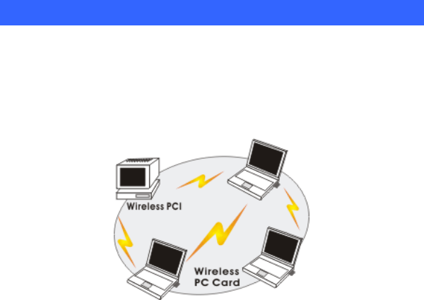
The Peer-to-Peer Network
This network installation lets you set a small wireless workgroup easily and
quickly. Equipped with wireless PC Cards or wireless PCI, you can share files
and printers between each PC and laptop.
- 2 -
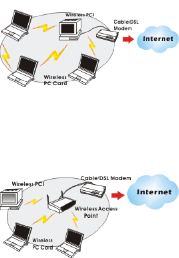
You can also use one computer as an Internet Server to connect to a wired global
network and share files and information with other computers via a wireless LAN.
The Access Point Network
The network installation allows you to share files, printers, and Internet access
much more conveniently. With Wireless LAN Cards, you can connect wireless
LAN to a wired global network via an Access Point.
- 3 -
INSTALLATION
Install the device
1. Make sure the computer is turned off. Remove the expansion
slot cover from the computer.
2. Carefully slide the 802.11n compliant 2.4GHz Mini-PCI
Module into the mini PCI slot. Push evenly and slowly and
ensure it is properly seated.
3. After the device has been connected to your computer, turn on
your computer. Windows will detect the new hardware and then
automatically copy all of the files needed for networking.
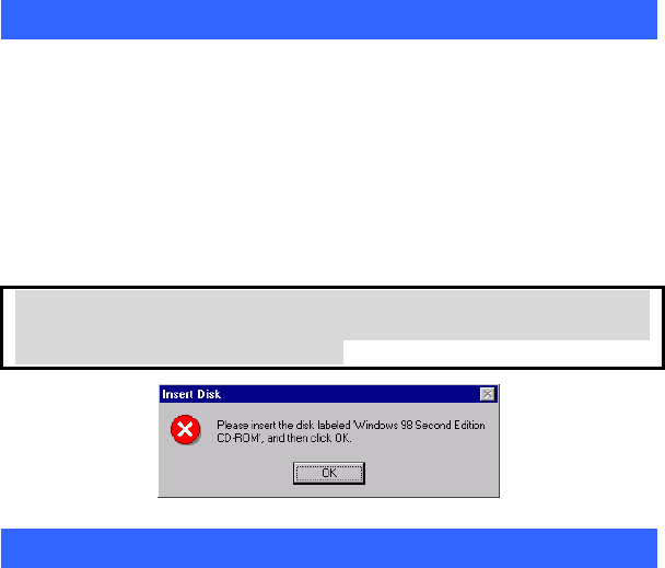
Note for Windows 98 users:
Before installation of the device, make sure you have your operating
system CD-ROM at hand. You may be asked to insert the OS CD-ROM
in order to download specific drivers.
Install the Driver & Utility
1. Exit all Windows programs. Insert the CD-ROM into the CD-ROM
drive of your computer.
• If the CD-ROM is not launched automatically, go to your CD-ROM drive (e.g.
drive D) and double-click on Setup.exe.
- 4 -
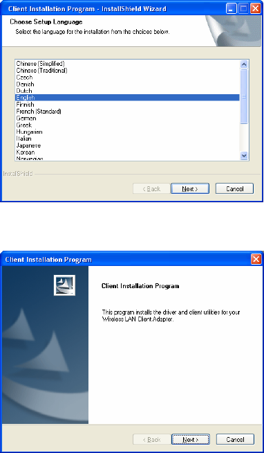
2. When the Choose Setup Language screen appears, select the
language you prefer and then click Next to continue.
3. Click Next to process the installation.
- 5 -
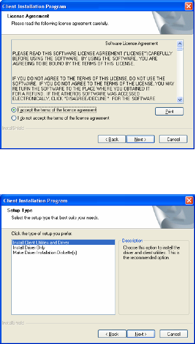
4. When the License Agreement screen appears, select “I accept the
terms of the license agreement” view the contents and then click
Next to continue.
4. When it comes to Setup Type screen, choose “Install Client
Utilities and Driver” then click Next.
- 6 -
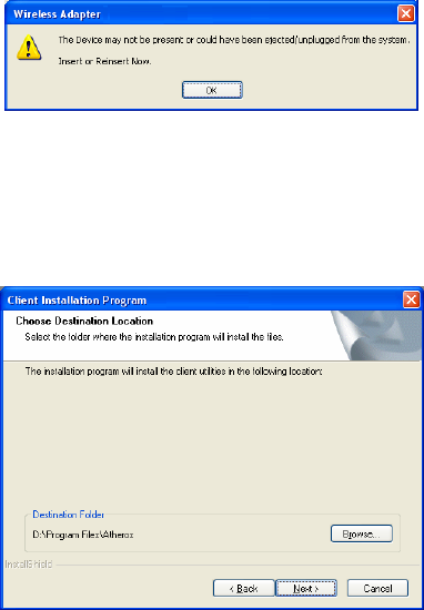
5. When this window comes up, please insert the wireless device and
click OK to continue.
6. Click Browse button to choose the destination location you prefer, or
use the default location, click Next to process.
- 7 -
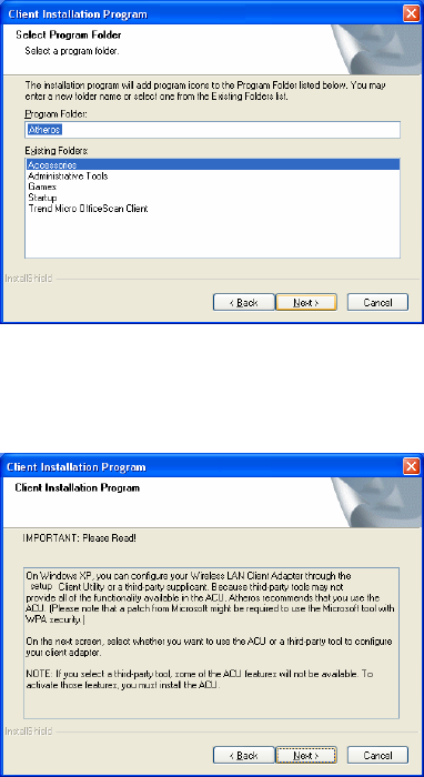
7. Select existing program folder you prefer, or enter a new folder name
then click Next.
8. Read the important notice the click Next to continue.
- 8 -
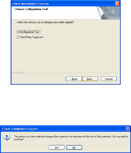
9. Select the check box to choose a Configuration Tool from the listed
two choices.
z Configuration Tool: Choose to use our configuration utility.
z Microsoft Zero Configuration Tool: Choose to use Windows XP’s
built-in Zero Configuration Utility (ZCU).
Click Next to continue.
10. Click Yes to reboot the system after complete the software
installation.
- 9 -
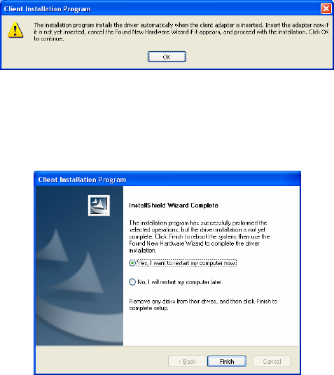
11. When this window shows up, the driver will be installed
automatically, click OK to continue.
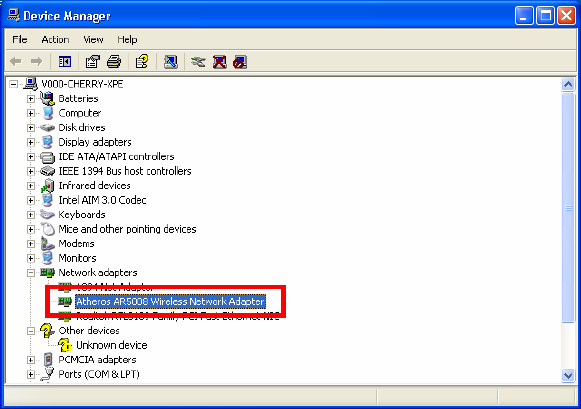
12. Select “Yes, I want to restart my computer now.” Then click
Finish to complete the installation.
- 10 -
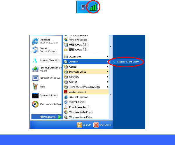
Verify Device Installation
To verify that the device has been properly installed in your computer and is
enabled, go to Start Æ Settings Æ Control Panel Æ System (Æ Hardware) Æ
Device Manager. Expand the Network adapters item. If the Atheros AR5008
Wireless Netwrok Adapter is listed, it means that your device is properly
installed and enabled.
- 11 -
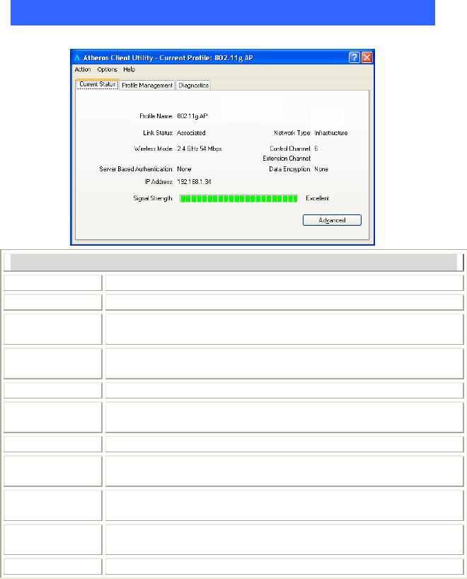
CONFIGURATION
After successful installation of the Wireless Netwrok Adapter driver, the utility
icon will be displayed on the task bar. You will be able to access the
Configuration Utility through the Network Status icon.
If the icon doesn’t appear automatically, go to Start Æ Programs Æ Wireless
Utility Æ Wireless Utility, it will appear in the task bar.
Accessing the Configuration Utility
All settings are categorized into three Tabs:
Current Status Tab
Profile Manager Tab
Diagnostics Tab
- 12 -
Current Status Tab
Current Status shows the profiles information of the connection.
Current Status Tab
Profile Name Show the profile names that are saved in your profile page.
Link Status Shows the current connection status.
Wireless Mode AP support wireless mode. It may support 802.11a, 802.11b,
802.11g or 802.11n wireless mode.
Server Based
Authentication Shows the network authentication in use.
IP Address Shows the IP address information.
Signal
Strength Shows the signal strength.
Network Type Shows the Network type of the profile.
Control
Channel The channel that is currently used.
Extension
Channel Show the extension channel.
Data
Encryption Shows the encryption type of the profile.
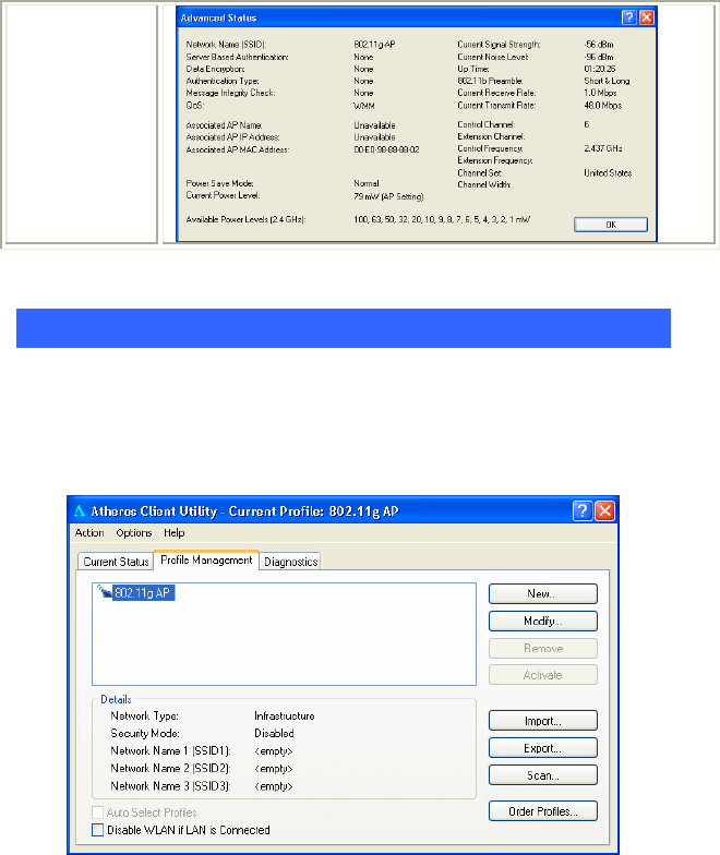
Advanced Click this button to show the detail information of the device.
- 13 -
Profile Manager Tab
Profile can book keeping your favorite wireless setting among your home, office,
and other public hot-spot. You may save multiple profiles, and activate the correct
one at your preference. The Profile manager enables you to New (Add), Modify,
Remove, Activate, import, export and order profiles.
- 14 -
Profile Manager Tab
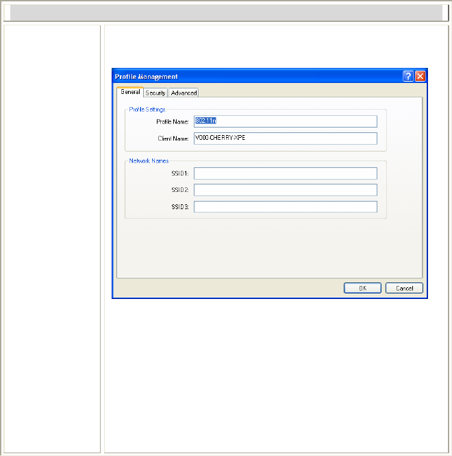
New Click the New button to add up a new profile into the list and
configure your profile settings.
General Tab:
Profile Settings:
Profile Name: You must enter a profile name in this blank.
Client Name: Shows the client information.
Network Names:
SSID: The SSID is the unique name shared among all points in
your wireless network. The name must be identical for all
devices and points attempting to connect to the same network.
OK: Click to save and exit the current page.
Cancel: Click to exit the current page.
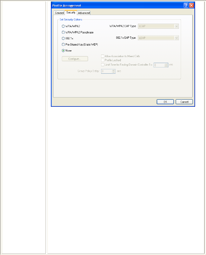
Security Tab:
- 15 -
Set Security Options: Select an authentication type from the
below list, including WPA/WPA2, WPA/WPA2 Passphrase,
802.1x, Pre-Shared Key (Static WEP) and None.
• WPA/WPA2: Enables the use of Wi-Fi Protected Access
(WPA). Choosing WPA/WPA2 opens the WPA/WPA2 EAP
drop-down menu. The options include:
• EAP-FAST
• EAP-TLS
• EAP-TTLS
• PEAP (EAP-GTC)
• PEAP (EAP-MSCHAP V2)
• LEAP
• WPA/WPA2 Passphrase: Enables WPA/WPA2 Passphrase
security. Click on the Configure button and fill in the
WPA/WPA2 Passphrase.
• 802.1x: Enables 802.1x security. This option requires IT
administration. Choosing 802.1x opens the 802.1x EAP type
drop-down menu. The options include:
• EAP-FAST
• EAP-TLS
• EAP-TTLS

- 16 -
• PEAP (EAP-GTC)
• PEAP (EAP-MSCHAP V2)
• LEAP
If the access point that the wireless adapter is associating to
has WEP set to Optional and the client has WEP enabled,
make sure that Allow Association to Mixed Cells is checked
on the Security Tab to allow association.
• Pre-Shared Key (Static WEP): Enables the use of pre-shared
keys that are defined on both the access point and the station.
To define pre-shared encryption keys, choose the Pre-Shared
Key and click the Configure button to fill in the Define
Pre-Shared Keys. If the access point that the wireless adapter
is associating to has WEP set to Optional and the client has
WEP enabled, make sure that Allow Association to Mixed
Cells is checked on the Security Tab to allow association.
• None: No security (not recommended).
Allow Association to Mixed Cells: Check this check box if the
access point with which the client adapter is to associate has WEP
set to Optional and WEP is enabled on the client adapter.
Otherwise, the client is unable to establish a connection with the
access point.
Profile Locked: Choose this to active the function.
Limit Time for Finding Domain Controller to: Check this
check box and enter the number of seconds (up to 300) after
which the authentication process times out when trying to find the
domain controller. Entering zero is like unchecking this check
box, which means no time limit is imposed for finding the domain
controller.
Note: The authentication process times out whenever the
authentication timer times out or the time for finding the
domain controller is reached.
Group Policy Delay: Specify how much time elapses before the
Windows logon process starts group policy. Group policy is a
Windows feature used by administrators to specify configuration
options for groups of users. The objective is to delay the start of
Group Policy until wireless network authentication occurs. Valid
ranges are from 0 to 65535 seconds. The value that you set goes
into effect after you reboot your computer with this profile set as
the active profile.
- 17 -
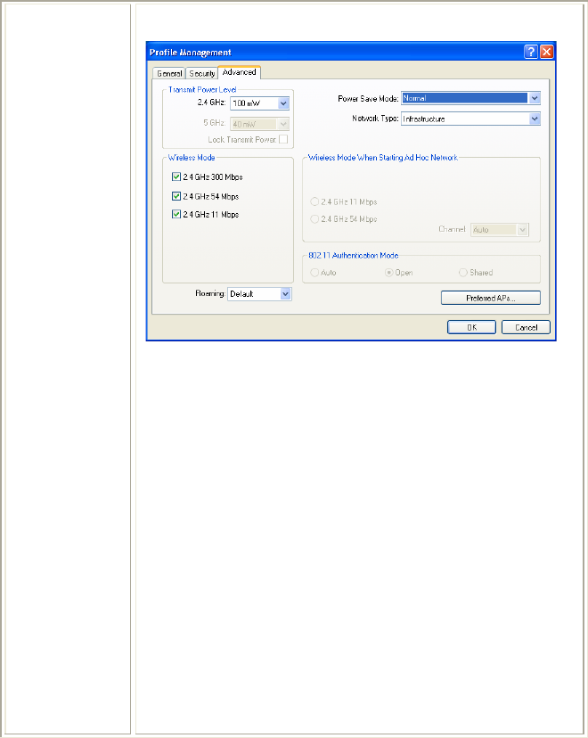
Advanced Tab-
Transmit Power Level: Selects the transmit power level for
80211b/g or 802.11a in mW. Actual transmit power may be
limited by regulatory domain or hardware limitations. Also note
that administrator has the privilege of locking these power levels,
so that these values are pre-selected and not editable.
Power Save Mode:
• Maximum mode causes the access point to buffer incoming
messages for the wireless adapter. The adapter periodically
polls the access point to see if any messages are waiting.
• Normal uses maximum when retrieving a large number of
packets, then switches back to power save mode after retrieving
the packets.
• Off turns power saving off, thus powering up the wireless
adapter continuously for a short message response time.
Network Type: Specifies the network as either infrastructure
(access point mode) or ad hoc.
Wireless mode: Specifies 2.4 GHz 300Mbps, 2.4 GHz 54Mbps,
2.4 GHz 11Mbps, Quality of Service. The wireless adapter must
match the wireless mode of the access point it associates to.
Wireless Mode when Starting an Ad Hoc Network: Specifies
2.4 GHz 11Mbps and 2.4 GHz 54Mbps to start an ad hoc network

- 18 -
if no matching network name is found after scanning all available
modes. This mode also allows selection of the channel the
wireless adapter uses. The channels available depend on the
regulatory domain. If the adapter finds no other ad hoc adapters,
this selection specifies the channel with the adapter starts the ad
hoc network with. The wireless adapter must match the wireless
mode and channel of the clients it associates to.
802.11 Authentication Mode: Select what mode the wireless
adapter uses to authenticate to an access point:
• Auto causes the adapter to attempt authentication using shared,
but switches it to open authentication if shared fails.
• Open enables an adapter to attempt authentication regardless of
its WEP settings. It will only associate with the access point if
the WEP keys on both the adapter and the access point match.
• Shared only allows the adapter to associate with access points
that have the same WEP key.
Roaming Strength: Select the roaming level to suit the roaming
aggressiveness of the client. Five roaming levels ranging from
Very Low to Very High allow for the best performance in
different environments such as home or office.
For infrastructure (access point) networks, click the Preferred APs
button to specify up to four access points to which the client
adapter should attempt to associate.
OK: Click to save and exit the current page.
Cancel: Click to exit the current page.
Modify Click to edit your existing profiles.
Remove Select the profile to remove from the list of configuration profiles.
Activate Click to activate your existing profiles.
Import Click the Import button then browse to the directory where the
profile is located.
Export Click the Export button then browse to the directory to export the
profile to.
Scan Click the Scan button to scan for available infrastructure and ad
hoc networks. On this list, click Refresh to refresh the list at any
time. Highlight a network name and click the Activate button to
connect an available network.
- 19 -
Order profiles Click this button to manage the profiles.
Auto Select
Profiles When auto profile selection is enabled, the client adapter scans for
an available network. The profile with the highest priority and the
same SSID as one of the found networks is the one that is used to
connect to the network. If the connection fails, the client adapter
tries the next highest priority profile that matches the SSID, and
so on.
Disable WLAN
if LAN is
connected
A connected WLAN is automatically disabled when a LAN
connects. This WLAN automatically is re-enabled when the LAN
is not available.
OK Click to save and exit the current page.
Cancel Click to exit the current page.
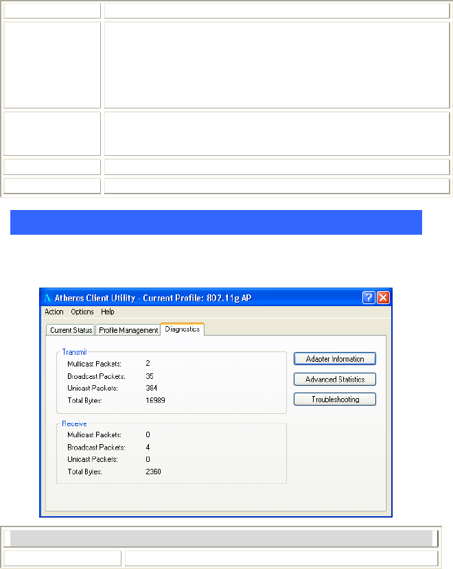
Diagnostics Tab
The Diagnostics tab lists the following receive and transmit diagnostics for frames
received by or transmitted by the wireless network adapter.
Diagnostics Tab
Multicast packets Shows the transmitted and received.
- 20 -
Broadcast packets Shows the transmitted and received.
Unicast packets Shows transmitted and received.
Total bytes Shows transmitted and received.
Adapter
Information Click the button for more general information about the
wireless network adapter and the network driver interface
specification driver.
Advanced Statistics Click the button on the Diagnostics tab to also show receive
and transmit statistical information.
Troubleshooting Click the Troubleshooting button to run the
Troubleshooting Utility.
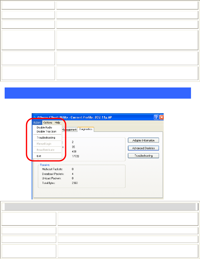
Action
Use the Action menu to access the Client Utility tools:
Action
Disable Radio Enable or disable the RF Signal on all station reference
designs.
Disable Tray Icon Enable or disable the tray icon.
Troubleshooting Run the optional Troubleshooting Utility.
Manual Login Log in to LEAP manually, if LEAP is set to manually
prompt for user name and password on each login.
- 21 -
Reauthenticate Reauthenticate to a LEAP-configured access point.
Exit Exit the Client Utility application.
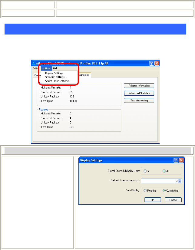
Options
The display settings dialog box contains tools to set the display settings, scan list
settings and select client software.
Options
Display Settings
Signal Strength Display Units: Sets the units
used when displaying signal strength: percentage
(%) or dBm.
Refresh Interval: Use the up/down arrows to set
the display refresh interval in seconds.
Data Display: Sets the display to cumulative or
relative:
- 22 -
• Relative displays the change in statistical data
since the last update.
• Cumulative displays statistical data collected
since opening the profile.
OK: Click to save and exit the current page.
Cancel: Click to exit the current page.
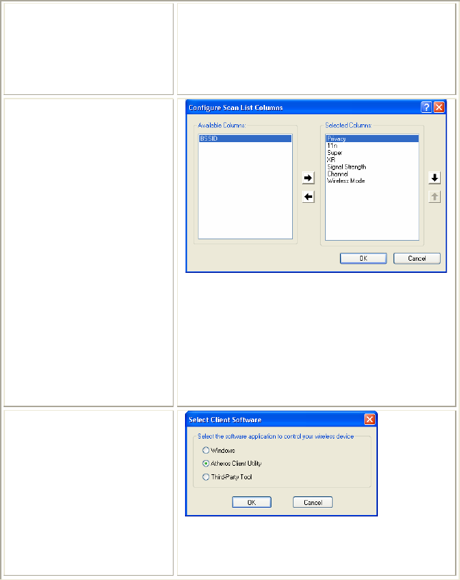
Scan List Settings
Available Columns: Displays the columns
available to use for the scan list.
Selected Columns: Displays the columns selected
for the scan list. Use the up/down arrows to
change the column order. To remove a column,
highlight the column then click the left arrow to
remove it from the Selected Columns list.
After selecting the required columns, click OK to
continue or Cancel to ignore.
Select Client Software
Select a software application you prefer to control
your wireless device.
OK: Click to save and exit the current page.
Cancel: Click to exit the current page.
- 23 -
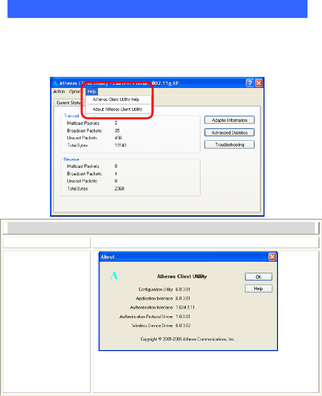
Help
The Client Utility is a user-mode utility designed to edit and add profiles for, as
well as display and diagnostics pertaining to a selected network interface card
(wireless adapter).
Help
Client Utility Help Select to see the Client Utility Help files.
About Client Utility
Shows the version numbers of various software
components.
OK: Click to save and exit the current page.
Help: Select to see the Client Utility help files.
- 24 -
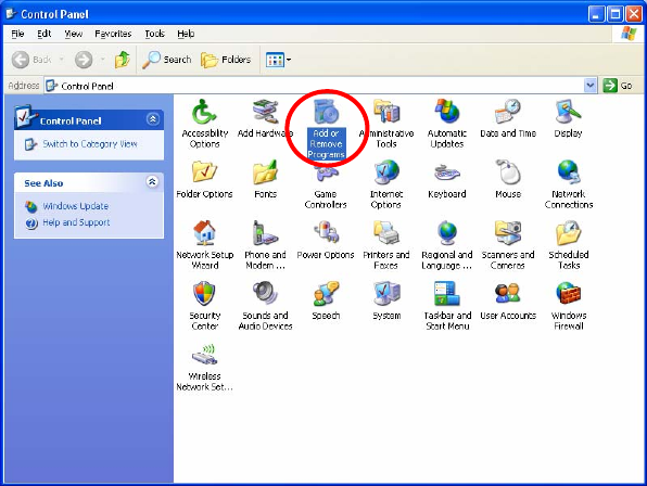
UNINSTALLATION
In case you need to uninstall the Utility and driver, please refer to below steps.
(As you uninstall the utility, the driver will be uninstalled as well.)
1. Go to Start Æ Control Panel Æ Add or Remove Programs.
- 25 -
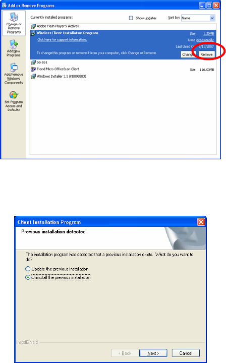
2. Select Wireless Client Installation Program, then click Remove to
process uninstallation.
3. When below window appears, select “Uninstall the previous
installation” then click Next to continue.
- 26 -
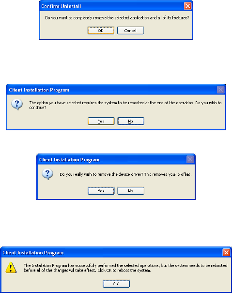
4. When the screen pops up, click OK to remove the selected
application.
5. Click Yes to reboot the system after complete the software
uninstallation.
6. Click Yes to confirm the software removing.
7. When this window shows up, click OK to reboot the computer to
complete the uninstallation.