Accton Technology 2804WBR Barricade g 2.4GHz 54 Mbps Wireless Router User Manual SMC2804wbr v 2
Accton Technology Corp Barricade g 2.4GHz 54 Mbps Wireless Router SMC2804wbr v 2
Contents
- 1. Users Manual 1
- 2. Users Manual 2
- 3. Users Manual 3
Users Manual 1

38 Tesla
Irvine, CA 92618
Phone: (949) 679-8000
BarricadeTM g 2.4 GHz 54 Mbps
Wireless Cable/DSL Broadband Router
From SMC’s Barricade line of Broadband Routers
July 2003
Revision Number: V.2 R01

COPYRIGHT
Information furnished by SMC Networks, Inc. (SMC) is believed to be accurate and reliable.
However, no responsibility is assumed by SMC for its use, nor for any infringements of patents
or other rights of third parties which may result from its use. No license is granted by
implication or otherwise under any patent or patent rights of SMC. SMC reserves the right to
change specifications at any time without notice.
Copyright © 2003 by
SMC Networks, Inc.
38 Tesla
Irvine, CA 92618
All rights reserved.
Trademarks:
SMC is a registered trademark; and Barricade is a trademark of SMC Networks, Inc. Other
product and company names are trademarks or registered trademarks of their respective
holders.

i
COMPLIANCES
Federal Communication Commission Interference
Statement
This equipment has been tested and found to comply with the limits for a Class B
digital device, pursuant to Part 15 of the FCC Rules. These limits are designed to
provide reasonable protection against harmful interference in a residential
installation. This equipment generates, uses and can radiate radio frequency
energy and, if not installed and used in accordance with the instructions, may
cause harmful interference to radio communications. However, there is no
guarantee that interference will not occur in a particular installation. If this
equipment does cause harmful interference to radio or television reception, which
can be determined by turning the equipment off and on, the user is encouraged to
try to correct the interference by one of the following measures:
•Reorient or relocate the receiving antenna
•Increase the separation between the equipment and receiver
•Connect the equipment into an outlet on a circuit different from that to which the
receiver is connected
•Consult the dealer or an experienced radio/TV technician for help
FCC Caution: To assure continued compliance, (example - use only shielded
interface cables when connecting to computer or peripheral devices) any changes
or modifications not expressly approved by the party responsible for compliance
could void the user's authority to operate this equipment. This device complies
with Part 15 of the FCC Rules. Operation is subject to the following two conditions:
(1) This device may not cause harmful interference, and (2) this device must
accept any interference received, including interference that may cause undesired
operation.
IMPORTANT NOTE:
FCC Radiation Exposure Statement
This equipment complies with FCC radiation exposure limits set forth for an
uncontrolled environment. This equipment should be installed and operated with a
minimum distance of 20 centimeters (8 inches) between the radiator and your
body. This transmitter must not be co-located or operating in conjunction with any
other antenna or transmitter.

Compliances
ii
EC Conformance Declaration - Class B
SMC contact for these products in Europe is:
SMC Networks Europe,
Edificio Conata II,
Calle Fructuós Gelabert 6-8, 2o, 4a,
08970 - Sant Joan Despí,
Barcelona, Spain.
This information technology equipment complies with the requirements of the
Council Directive 89/336/EEC on the Approximation of the laws of the Member
States relating to Electromagnetic Compatibility and 73/23/EEC for electrical
equipment used within certain voltage limits and the Amendment Directive 93/68/
EEC. For the evaluation of the compliance with these Directives, the following
standards were applied:
RFI
Emission:
* Limit class B according to EN 55022:1998
* Limit class B for harmonic current emission according to EN 61000-3-2/
1995
* Limitation of voltage fluctuation and flicker in low-voltage supply system
according to EN 61000-3-3/1995
Immunity: * Product family standard according to EN 55024:1998
* Electrostatic Discharge according to EN 61000-4-2:1995
(Contact Discharge: ±4 kV, Air Discharge: ±8 kV)
* Radio-frequency electromagnetic field according to EN 61000-4-3: 1996
(80 - 1000 MHz with 1 kHz AM 80% Modulation: 3 V/m)
* Electrical fast transient/burst according to EN 61000-4-4:1995(AC/DC
power supply: ±1 kV, Data/Signal lines: ±0.5 kV)
* Surge immunity test according to EN 61000-4-5:1995(AC/DC Line to
Line: ±1 kV, AC/DC Line to Earth: ±2 kV)
* Immunity to conducted disturbances, Induced by radio-frequency fields:
EN 61000-4-6:1996(0.15 - 80 MHz with 1 kHz AM 80% Modulation:
3V/m)
* Power frequency magnetic field immunity test according to EN
61000-4-8:1993(1 A/m at frequency 50 Hz)
* Voltage dips, short interruptions and voltage variations immunity test
according to EN 61000-4-11:1994(>95% Reduction @10 ms, 30%
Reduction @500 ms, >95% Reduction @5000 ms)
LVD: * EN60950(A1/1992; A2/1993; A3/1993; A4/1995; A11/1997)

Compliances
iii
Industry Canada - Class B
This digital apparatus does not exceed the Class B limits for radio noise emissions
from digital apparatus as set out in the interference-causing equipment standard
entitled “Digital Apparatus,” ICES-003 of the Department of Communications.
Cet appareil numérique respecte les limites de bruits radioélectriques applicables
aux appareils numériques de Classe B prescrites dans la norme sur le matériel
brouilleur: “Appareils Numériques,” NMB-003 édictée par le ministère des
Communications.
Australia AS/NZS 3548 (1995) - Class B
SMC contact for products in Australia is:
SMC Communications Pty. Ltd.
Suite 18, 12 Tryon Road,
Lindfield NSW2070,
Phone: 61-2-8875-7887
Fax: 61-2-8875-7777
Safety Compliance
Underwriters Laboratories Compliance Statement
Important! Before making connections, make sure you have the correct cord set.
Check it (read the label on the cable) against the following:
The unit automatically matches the connected input voltage. Therefore, no
additional adjustments are necessary when connecting it to any input voltage
within the range marked on the rear panel.
Operating Voltage Cord Set Specifications
120 Volts UL Listed/CSA Certified Cord Set
Minimum 18 AWG
Type SVT or SJT three conductor cord
Maximum length of 15 feet
Parallel blade, grounding type attachment plug
rated 15 A, 125 V
240 Volts (Europe only) Cord Set with H05VV-F cord having three
conductors with minimum diameter of 0.75 mm2
IEC-320 receptacle
Male plug rated 10 A, 250 V

Compliances
iv
Wichtige Sicherheitshinweise (Germany)
1. Bitte lesen Sie diese Hinweise sorgfältig durch.
2. Heben Sie diese Anleitung für den späteren Gebrauch auf.
3. Vor jedem Reinigen ist das Gerät vom Stromnetz zu trennen. Verwenden Sie
keine Flüssigoder Aerosolreiniger. Am besten eignet sich ein angefeuchtetes
Tuch zur Reinigung.
4. Die Netzanschlu ßsteckdose soll nahe dem Gerät angebracht und leicht
zugänglich sein.
5. Das Gerät ist vor Feuchtigkeit zu schützen.
6. Bei der Aufstellung des Gerätes ist auf sicheren Stand zu achten. Ein Kippen
oder Fallen könnte Beschädigungen hervorrufen.
7. Die Belüftungsöffnungen dienen der Luftzirkulation, die das Gerät vor
Überhitzung schützt. Sorgen Sie dafür, daß diese Öffnungen nicht abgedeckt
werden.
8. Beachten Sie beim Anschluß an das Stromnetz die Anschlußwerte.
9. Verlegen Sie die Netzanschlußleitung so, daß niemand darüber fallen kann.
Es sollte auch nichts auf der Leitung abgestellt werden.
10. Alle Hinweise und Warnungen, die sich am Gerät befinden, sind zu beachten.
11. Wird das Gerät über einen längeren Zeitraum nicht benutzt, sollten Sie es vom
Stromnetz trennen. Somit wird im Falle einer Überspannung eine
Beschädigung vermieden.
12. Durch die Lüftungsöffnungen dürfen niemals Gegenstände oder Flüssigkeiten
in das Gerät gelangen. Dies könnte einen Brand bzw. elektrischen Schlag
auslösen.
13. Öffnen sie niemals das Gerät. Das Gerät darf aus Gründen der elektrischen
Sicherheit nur von authorisiertem Servicepersonal geöffnet werden.
14. Wenn folgende Situationen auftreten ist das Gerät vom Stromnetz zu trennen
und von einer qualifizierten Servicestelle zu überprüfen:
a. Netzkabel oder Netzstecker sind beschädigt.
b. Flüssigkeit ist in das Gerät eingedrungen.
c. Das Gerät war Feuchtigkeit ausgesetzt.
d. Wenn das Gerät nicht der Bedienungsanleitung entsprechend funktioniert
oder Sie mit Hilfe dieser Anleitung keine Verbesserung erzielen.
e. Das Gerät ist gefallen und/oder das Gehäuse ist beschädigt.
f. Wenn das Gerät deutliche Anzeichen eines Defektes aufweist.
15. Stellen Sie sicher, daß die Stromversorgung dieses Gerätes nach der EN
60950 geprüft ist. Ausgangswerte der Stromversorgung sollten die Werte von
AC 7,5-8 V, 50-60 Hz nicht über oder unterschreiten sowie den minimalen
Strom von 1 A nicht unterschreiten.
Der arbeitsplatzbezogene Schalldruckpegel nach DIN 45 635 Teil 1000 beträgt
70 dB(A) oder weniger.

v
T
ABLE
OF
C
ONTENTS
About the Wireless Barricade g Router . . . . . . . . 1
LED Indicators . . . . . . . . . . . . . . . . . . . . . . . . . . . . . . . . . . . . . . 1
Features and Benefits . . . . . . . . . . . . . . . . . . . . . . . . . . . . . . . . 2
Installing the Wireless Barricade g Router . . . . . . 3
Package Contents . . . . . . . . . . . . . . . . . . . . . . . . . . . . . . . . . . . 3
Hardware Description . . . . . . . . . . . . . . . . . . . . . . . . . . . . . . . . . 4
System Requirements . . . . . . . . . . . . . . . . . . . . . . . . . . . . . . . . 6
Connect the System . . . . . . . . . . . . . . . . . . . . . . . . . . . . . . . . . . 6
Basic Installation Procedure . . . . . . . . . . . . . . . . . . . . . . . 7
Configuring Client TCP/IP . . . . . . . . . . . . . . . . . . 12
Installing TCP/IP . . . . . . . . . . . . . . . . . . . . . . . . . . . . . . . . . . . . 12
Windows 95/98/Me . . . . . . . . . . . . . . . . . . . . . . . . . . . . . 12
Windows 2000 . . . . . . . . . . . . . . . . . . . . . . . . . . . . . . . . 13
Setting Up TCP/IP . . . . . . . . . . . . . . . . . . . . . . . . . . . . . . . . . . 15
Configuring Your Computer in Windows 95/98/Me . . . . . 15
Configuring Your Computer in Windows NT 4.0 . . . . . . . 18
Configuring Your Computer in Windows 2000 . . . . . . . . 20
Configuring Your Computer in Windows XP . . . . . . . . . . 21
Configuring a Macintosh Computer . . . . . . . . . . . . . . . . 22
Manual IP Configuration (for all Windows OS) . . . . . . . . 23
Verifying Your TCP/IP Connection . . . . . . . . . . . . . . . . . 25
Configuring the Wireless Barricade g Router . . 26
Browser Configuration . . . . . . . . . . . . . . . . . . . . . . . . . . . . . . . 26
Disable Proxy Connection . . . . . . . . . . . . . . . . . . . . . . . 27
Navigating the Web Browser Interface . . . . . . . . . . . . . . . . . . . 28
Making Configuration Changes . . . . . . . . . . . . . . . . . . . 29
Setup Wizard . . . . . . . . . . . . . . . . . . . . . . . . . . . . . . . . . . . . . . 30
Time Zone . . . . . . . . . . . . . . . . . . . . . . . . . . . . . . . . . . . . 30
Broadband Type . . . . . . . . . . . . . . . . . . . . . . . . . . . . . . . 31
Advanced Setup . . . . . . . . . . . . . . . . . . . . . . . . . . . . . . . . . . . . 34
System . . . . . . . . . . . . . . . . . . . . . . . . . . . . . . . . . . . . . . 36
WAN . . . . . . . . . . . . . . . . . . . . . . . . . . . . . . . . . . . . . . . . 39

T
ABLE
OF
C
ONTENTS
vi
LAN . . . . . . . . . . . . . . . . . . . . . . . . . . . . . . . . . . . . . . . . 45
Wireless . . . . . . . . . . . . . . . . . . . . . . . . . . . . . . . . . . . . . 46
NAT - Network Address Translation . . . . . . . . . . . . . . . . 50
Firewall . . . . . . . . . . . . . . . . . . . . . . . . . . . . . . . . . . . . . . 53
DDNS (Dynamic DNS) Settings . . . . . . . . . . . . . . . . . . . 62
UPnP (Universal Plug and Play) Setting . . . . . . . . . . . . 63
Tools . . . . . . . . . . . . . . . . . . . . . . . . . . . . . . . . . . . . . . . 64
Status . . . . . . . . . . . . . . . . . . . . . . . . . . . . . . . . . . . . . . . 67
Troubleshooting . . . . . . . . . . . . . . . . . . . . . . . . . .68
Specifications . . . . . . . . . . . . . . . . . . . . . . . . . . . .71
1
ABOUT THE WIRELESS
BARRICADE G ROUTER
Congratulations on your purchase of the Wireless Barricade™ g
Broadband Router. SMC is proud to provide you with a powerful
yet simple communication device for connecting your local area
network (LAN) to the Internet.
LED Indicators
The Wireless Barricade g Router includes status LED indicators,
as described in the following figure and table.
LED Status Description
PWR
(Green) On The Wireless Barricade g Router is receiving power.
WLAN
(Green) On The Wireless Barricade g Router has established a valid
wireless connection.
WAN
(Green) On The WAN port has established a valid network
connection.
Link/ACT
(Green) On The indicated LAN port has established a valid network
connection.
Flashing The indicated LAN port is transmitting or receiving
traffic.
Speed
(Amber) Off The indicated LAN port has established a valid 10 Mbps
network connection.
On The indicated LAN port has established a valid
100 Mbps network connection.
SMC7004AWBR
LAN 1PWR WLAN WAN 2 3
Link
Activity

About the Wireless Barricade g Router
2
Features and Benefits
•Internet connection to DSL or cable modem via
a 10/100 Mbps WAN port
•Local network connection via 10/100 Mbps Ethernet ports or
54 Mbps wireless interface (supporting up to 253 mobile
users)
•802.11g draft Compliant – interoperable with multiple vendors
•Advanced security through 64/128-bit WEP encryption,
802.1x, SSID broadcast disabled, and MAC address filtering
features to protect your sensitve data and authenticate only
authorized users to your network
•Provides seamless roaming within 802.11g draft WLAN
environment
•DHCP for dynamic IP configuration, and DNS for domain
name mapping
•Firewall with Stateful Packet Inspection, client privileges,
hacker prevention, DoS, and NAT
•NAT also enables multi-user access with a single-user
account, and virtual server functionality (providing protected
access to Internet services such as web, mail, FTP, and
Telnet)
•Virtual Private Network support using PPTP, L2TP, or IPSec
pass-through
•User-definable application sensing tunnel supports
applications requiring multiple connections
•Parental controls allow the user to restrict web browsing
•Automatic E-mail alerts when the network is being attacked
•Easy setup through a web browser on any operating system
that supports TCP/IP
•Compatible with all popular Internet applications

3
INSTALLING THE WIRELESS
BARRICADE G ROUTER
Before installing the Wireless Barricade™ g Broadband Router,
verify that you have all the items listed under “Package
Contents.” If any of the items are missing or damaged, contact
your local SMC distributor. Also be sure that you have all the
necessary cabling before installing the Router. After installing the
Router, refer to the web-based configuration program in
“Configuring the Wireless Barricade g Router” on page 26 for
information on configuring the Router.
Package Contents
After unpacking the Wireless Barricade g Broadband Router,
check the contents of the box to be sure you have received the
following components:
•Wireless Barricade g Broadband Router
•Power adapter
•One CAT-5 Ethernet cable
•Four rubber feet
•Installation CD containing this User Guide and EZ 3-Click
Installation Wizard
•Quick Installation Guide
Immediately inform your dealer in the event of any incorrect,
missing or damaged parts. If possible, please retain the carton
and original packing materials in case there is a need to return
the product.
Please register on SMC’s web site at www.smc.com The
Wireless Barricade g Router is covered by a limited lifetime
warranty.

Installing the Wireless Barricade g Router
4
Hardware Description
The Router can be connected to the Internet or to a remote site
using its RJ-45 WAN port. It can be connected directly to your PC
or to a local area network using any of the Fast Ethernet LAN
ports.
Access speed to the Internet depends on your service type.
Full-rate ADSL can provide up to 8 Mbps downstream and
640 Kbps upstream. G.lite (or splitterless) ADSL provides up to
1.5 Mbps downstream and 512 Kbps upstream. Cable modems
can provide up to 36 Mbps downstream and 2 Mbps upstream.
ISDN can provide up to 128 Kbps when using two bearer
channels. PSTN analog connections can now run up to 56 Kbps.
However, you should note that the actual rate provided by
specific service providers may vary dramatically from these
upper limits.
Although access speed to the Internet is determined by the
modem type connected to the Router, data passing between
devices connected to your local area network can run up to
100 Mbps over the Fast Ethernet ports.
The Router includes an LED display on the front panel for system
power and port indications that simplifies installation and network
troubleshooting. It also provides four RJ-45 LAN ports and one
RJ-45 WAN port on the rear panel.
•4 RJ-45 ports for connection to a 10BASE-T/100BASE-TX
Ethernet Local Area Network (LAN). These ports can
auto-negotiate the operating speed to 10/100 Mbps, the mode
to half/full duplex, and the pin signals to MDI/MDI-X
(i.e., allowing these ports to be connected to any network
device with straight-through cable). These ports can be
connected directly to a PC or to a server equipped with an
Ethernet network interface card, or to a networking device
such as an Ethernet hub or switch.
Hardware Description
5
•One RJ-45 port for connection to a DSL or cable modem
(WAN). This port also auto-negotiates operating speed to
10/100 Mbps, the mode to half/full duplex, and the pin signals
to MDI/MDI-X.
The following figure shows the components of the Router:
Figure 1. Front and Rear Panels
Item Description
Reset
Button Use this button to reset the power and restore the default factory
settings.
LEDs Power, WLAN, WAN and LAN port status indicators.
(See “LED Indicators” on page 1.)
LAN
Ports Fast Ethernet ports (RJ-45). Connect devices (such as a PC, hub
or switch) on your local area network to these ports.
WAN
Port WAN port (RJ-45). Connect your cable modem, DSL modem, or an
Ethernet router to this port.
Power
Inlet Connect the included power adapter to this inlet.
Warning: Using the wrong type of power adapter may damage
your router.

Installing the Wireless Barricade g Router
6
System Requirements
You must have an ISP that meets the following minimum
requirements:
•Internet access from your local telephone company or Internet
Service Provider (ISP) using a DSL modem or cable modem.
•A PC using a fixed IP address or dynamic IP address
assigned via DHCP, as well as a Gateway server address and
DNS server address from your service provider.
•A computer equipped with a 10 Mbps, 100 Mbps, or
10/100 Mbps Fast Ethernet card, or a USB-to-Ethernet
converter.
•TCP/IP network protocol installed on each PC that needs to
access the Internet.
•A Java-enabled web browser, such as Microsoft Internet
Explorer 5.0 or above, or Netscape Communicator 4.0 or
above installed on one PC at your site for configuring the
Router.
Connect the System
The Router can be positioned at any convenient location in your
office or home. No special wiring or cooling requirements are
needed. You should, however comply with the following
guidelines:
•Keep the Router away from any heating devices.
•Do not place the Router in a dusty or wet environment.
You should also remember to turn off the power, remove the
power cord from the outlet, and keep your hands dry when you
install the Router.

Connect the System
7
Basic Installation Procedure
1. Connect the LAN: Connect the Router to your PC, or to a
hub or switch. Run Ethernet cable from one of the LAN ports
on the rear of the Router to your computer’s network adapter
or to another network device.
You may also connect the Router to your PC (using a
wireless client adapter) via radio signals. Position both
antennas on the back of the Router into the desired positions.
For more effective coverage, position the antennas along
different axex. For example, try positioning the antennas
around 45 to 90 degress apart. (The antennas emit signals
along the toroidal plane – and thus provide more
effective coverage when positioned along different
axes.)
2. Connect the WAN: Prepare an Ethernet cable for connecting
the
Router to a cable/xDSL modem or Ethernet router.
3. Power on: Connect the power adapter to the Router.
Figure 2. Connecting the Wireless Barricade g Router
Internet
Access
Device
Wireless
Router
Cable/DSL
Broadband
SOHO Office or Residence
SMC7004AWBR
LAN1
PWRWLAN WAN 23
Link
Activity
Notebook with
Wireless PC Card
Internet
Installing the Wireless Barricade g Router
8
Attach to Your Network Using Ethernet Cabling
The four LAN ports on the Router auto-negotiate the connection
speed to 10 Mbps Ethernet or 100 Mbps Fast Ethernet, and the
transmission mode to half duplex or full duplex.
Use twisted-pair cable to connect any of the four LAN ports on
the Router to an Ethernet adapter on your PC. Otherwise, you
can cascade any of the LAN ports on the Router to an Ethernet
hub or switch, and then connect your PC or other network
equipment to the hub or switch. When inserting an RJ-45 plug,
be sure the tab on the plug clicks into position to ensure that it is
properly seated.
Warning: Do not plug a phone jack connector into any RJ-45
port. This may damage the Router. Instead, use only
twisted-pair cables with RJ-45 connectors that conform
with FCC standards.
Figure 3. Making the LAN Connections

Connect the System
9
Attach to Your Network Using Radio Signals
Install a wireless network adapter in each computer that will be
connected to the Internet or your local network via radio signals.
SMC currently offers several wireless network cards, including
the
SMC2802W and SMC2835W wireless cards.
Rotate both antennas on the back of the Router to the desired
position. For more effective coverage, position the antennas
around 45 to 90 degrees apart. Try to place the Router in a
position that is located in the center of
your wireless network.
Normally, the higher you place the antenna,
the better the
performance. Ensure that the Router’s location provides optimal
reception throughout your home or office.
Computers equipped with a wireless adapter can communicate
with each other as an independent wireless LAN by configuring
each computer to the same radio channel. However, the Router
can provide access to your wired/wireless LAN or to the Internet
for all wireless workstations. Each wireless PC in this network
infrastructure can talk to any computer in the wireless group via a
radio link, or access other computers or network resources in the
wired LAN infrastructure or over the Internet via the Router.
The wireless infrastructure configuration not only extends the
accessibility of wireless PCs to the wired LAN, but also increases
the effective wireless transmission range for wireless PCs by
retransmitting incoming radio signals through the Router.
Installing the Wireless Barricade g Router
10
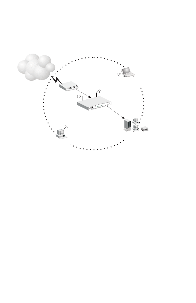
A wireless infrastructure can be used for access to a central
database, or for connection between mobile workers, as shown
in the following figure:
Figure 4. Making the WLAN Connections
Internet
Internet
Access
Device
Wireless
Router
Cable/DSL
Broadband
Notebook with Wireless
PC Card Adapter
PC with Wireless
PCI Adapter
Wired LAN
Wired to Wireless
Network Extension
SMC7004AWBR
LAN1
PWRWLAN WAN 23
Link
Activity
Connect the System
11
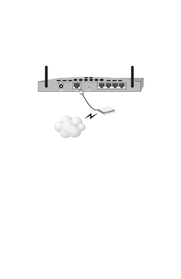
Attach the Wireless Barricade g Router to the Internet
If Internet services are provided through an xDSL or cable
modem, use unshielded or shielded twisted-pair Ethernet cable
(Category 3 or greater) with RJ-45 plugs to connect the
broadband modem directly to the WAN port on the Router.
Figure 5. Making the WAN Connection
Note: When connecting to the WAN port, use 100-ohm
Category 3, 4, or 5 shielded or unshielded twisted-pair
cable with RJ-45 connectors at both ends for all
connections.
Connecting the Power Adapter
Plug the power adapter into the power socket on the Router, and
the other end into a power outlet. Check the indicator marked
“PWR” on the front panel to be sure it is on. If the power i
ndicator
does not light, refer to
“Troubleshooting” on page 69
.
ISP
(Primary)
DSL/Cable
Modem
12
CONFIGURING
CLIENT TCP/IP
If you have not previously installed the TCP/IP protocols on your
client PCs, refer to the following section. If you need information
on how to configure a TCP/IP address on a PC, refer to “Setting
Up TCP/IP” on page 15.
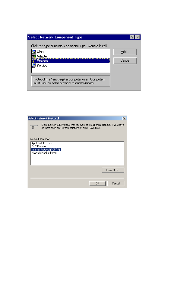
Installing TCP/IP
Windows 95/98/Me
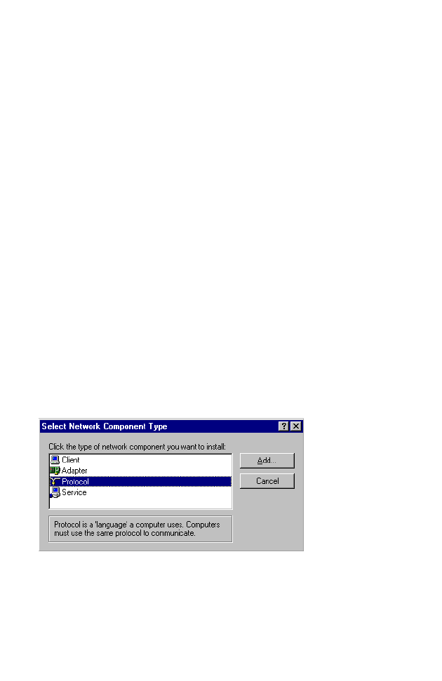
1. Click Start/Settings/Control Panel.
2. Double-click the Network icon and select the Configuration
tab in the Network window.
3. Click the Add button.
4. Double-click Protocol.
Installing TCP/IP
13
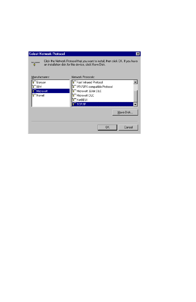
5. Select Microsoft in the manufacturers list. Select TCP/IP in
the Network Protocols list. Click the OK button to return to the
Network window.
6. The TCP/IP protocol will be listed in the Network window.
Click OK. The operating system may prompt you to restart
your system. Click Yes and the computer will shut down and
restart.
Windows 2000
1. Click the Start button and choose Settings, then click the
Network and Dial-up Connections icon.
2. Double-click the Local Area Connection icon, and click the
Properties button on the General tab.
3. Click the install... button.
Configuring Client TCP/IP
14
4. Double-click Protocol.
5. Choose Internet Protocol (TCP/IP). Click the OK button to
return to the Network window.
6. The TCP/IP protocol will be listed in the Network window.
Click OK to complete the installation procedure.

Setting Up TCP/IP
15
Setting Up TCP/IP
To access the Internet through the Router, you must configure
the network settings of the computers on your LAN to use the
same IP subnet as the Router. The default network settings for
the Router are:
Gateway IP Address: 192.168.2.1
Subnet Mask: 255.255.255.0
Note: These settings may be changed to suit your network
requirements, but you must first configure at least one
computer as described in this chapter to access the
Router’s web configuration interface. See “Configuring
the Wireless Barricade g Router” on page 26 for
information on configuring the Router.)
If you have not previously configured TCP/IP for your computer,
refer to“Configuring Client TCP/IP” on page 12. The IP address
of the connected client PC should be 192.168.2.x (where x
means 2–254). You can set the IP address for client PCs either
by automatically obtaining an IP address from the Router’s
DHCP service or by manual configuration.
Configuring Your Computer in Windows 95/98/Me
You may find that the instructions here do not exactly match your
version of Windows. This is because these steps and
screenshots were created in Windows 98. Windows 95 and
Windows Millennium Edition are very similar, but not identical, to
Windows 98.
1. From the Windows desktop, click Start/Settings/Control
Panel.
2. In the Control Panel, locate and double-click the Network
icon.
Configuring Client TCP/IP
16
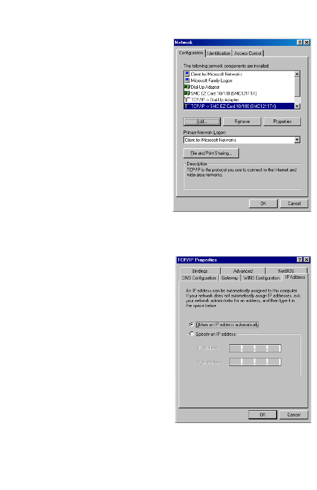
3. On the Network window
Configuration tab,
double-click the TCP/IP
entry for your network
card.
4. Click the IP Address tab.
5. Click the “Obtain an IP
address“ option.
6. Next click on the Gateway
tab and verify the Gateway
field is blank. If there are
IP addresses listed in the Gateway section, highlight each
one and click Remove until the section is empty.
7. Click the OK button to close the TCP/IP Properties window.
Setting Up TCP/IP
17
8. On the Network Properties Window, click the OK button to
save these new settings.
Note: Windows may ask you for the original Windows
installation disk or additional files. Check for the files at
c:\windows\options\cabs, or insert your Windows
CD-ROM into your CDROM drive and check the correct
file location, e.g., D:\win98, D:\win9x. (if D is the letter
of your CD-ROM drive).
9. Windows may prompt you to restart the PC. If so, click the Yes
button. If Windows does not prompt you to restart your
computer, do so to insure your settings.
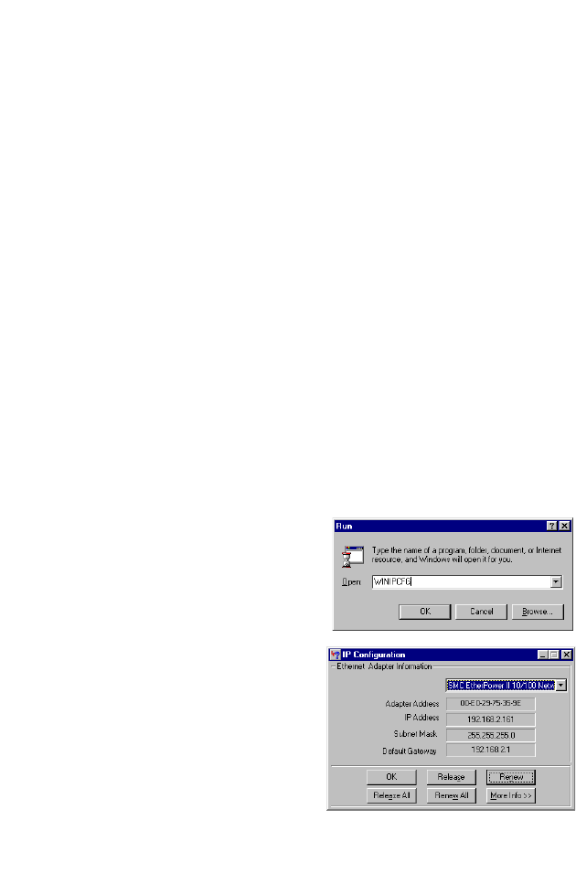
Obtain IP Settings from Your Wireless Barricade g Router
Now that you have configured your computer to connect to your
Router, it needs to obtain new network settings. By releasing old
IP settings and renewing them with settings from your Router,
you will also verify that you have configured your computer
correctly.
1. Click Start/Run.
2. Type WINIPCFG and click
OK.
3. From the drop-down menu,
select your network card.
Click Release and then
Renew. Verify that your IP
address is now
192.168.2.xxx, your Subnet
Mask is 255.255.255.0 and
your Default Gateway is
192.168. 2.1. These values
confirm that the Router is functioning. Click OK to close the IP
Configuration window.
Configuring Client TCP/IP
18
Configuring Your Computer in Windows NT 4.0
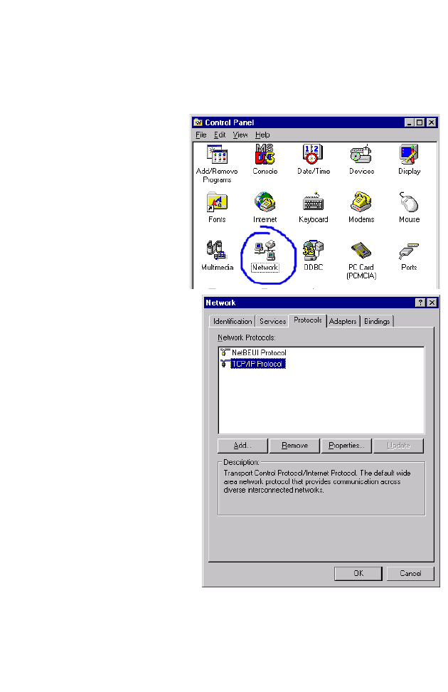
1. From the Windows desktop click Start/Settings/Control Panel.
2. Double-click the
Network icon.
3. Click on the
Protocols tab.
4. Double-click
TCP/IP Protocol.
5. Click on the IP
Address tab.
6. In the Adapter drop-down list, be sure your Ethernet adapter
is selected.
Setting Up TCP/IP
19
7. Click on “Obtain an IP address from a DHCP server.”
8. Click OK to close the window.
9. Windows may copy files and will then prompt you to restart
your system. Click Yes and your computer will shut down and
restart.
Obtain IP Settings From Your Wireless Barricade g Router
Now that you have configured your computer to connect to the
Router, it needs to obtain new network settings. By releasing old
IP settings and renewing them with settings from the Router, you
will also verify that you have configured your computer correctly.
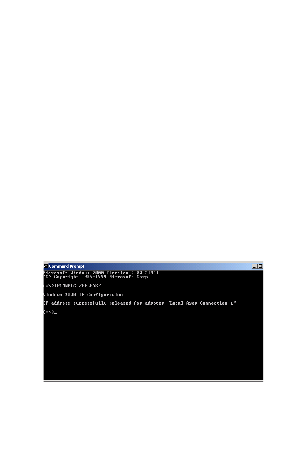
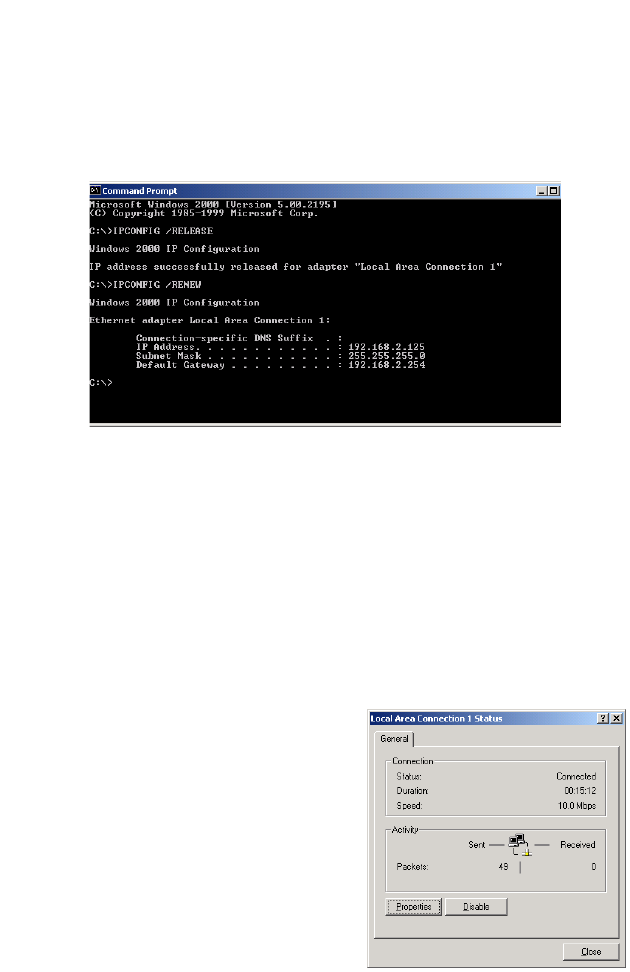
1. On the Windows desktop, click Start/Programs/Command
Prompt.
2. In the Command Prompt window, type IPCONFIG /RELEASE
and press the <ENTER> key.
Configuring Client TCP/IP
20
3. Type IPCONFIG /RENEW and press the <ENTER> key. Verify
that your IP Address is now 192.168.2.xxx, your Subnet Mask
is 255.255.255.0 and your Default Gateway is 192.168.2.1.
These values confirm that the Router is functioning
4. Type EXIT and press <ENTER> to close the Command
Prompt window.
Configuring Your Computer in Windows 2000
1. Access your Network settings by clicking Start, then choose
Settings and then select Control Panel.
2. In the Control Panel, locate and double-click the Network and
Dial-up Connections icon.
3. Locate and double-click the
Local Area Connection icon
for the Ethernet adapter that
is connected to the Router.
When the Status dialog box
window opens, click the
Properties button.

Setting Up TCP/IP
21
4. In the Local Area Connection Properties box, verify the box
next to Internet Protocol (TCP/IP) is checked. Then highlight
the Internet Protocol (TCP/IP), and click the Properties
button.
5. Select “Obtain an IP address automatically” to configure your
computer for DHCP. Click the OK button to save this change
and close the Properties window.
6. Click the OK button again to save these new changes.
7. Reboot your PC.
8. To obtain new network settings see “Obtain IP Settings from
Your Wireless Barricade g Router” on page 17.
Configuring Your Computer in Windows XP
The following instructions assume you are running Windows XP
with the default interface. If you are using the Classic interface
(where the icons and menus look like previous Windows
versions), please follow the instructions for Windows 2000
outlined above.
1. Access your Network settings by clicking Start, choose
Control Panel, select Network and Internet Connections and
then click on the Network Connections icon.
Configuring Client TCP/IP
22
2. Locate and double-click the
Local Area Connection icon
for the Ethernet adapter that
is connected to the Router.
Next, click the Properties
button.
3. In the Local Area Connection Properties box, verify the box
next to Internet Protocol (TCP/IP) is checked. Then highlight
the Internet Protocol (TCP/IP), and click the Properties
button.
4. Select “Obtain an IP address automatically” to configure your
computer for DHCP. Click the OK button to save this change
and close the Properties window.
5. Click the OK button again to save these new changes.
6. Reboot your PC.
Configuring a Macintosh Computer
You may find that the instructions here do not exactly match your
screen. This is because these steps and screenshots were
created using Mac OS 10.2. Mac OS 7.x and above are all very
similar, but may not be identical to Mac OS 10.2.
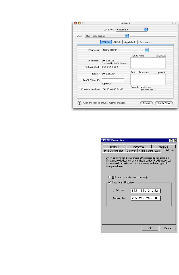
1. Pull down the Apple Menu. Click System Preferences and
select Network.
Setting Up TCP/IP
23
2. Make sure that
Built-in Ethernet
is selected in the
Show field.
3. On the TCP/IP
tab, select Using
DHCP in the
Configure field.
4. Close the
TCP/IP dialog
box.
Manual IP Configuration (for all Windows OS)
1. Check Specify an IP
address on the IP Address
tab. Enter an IP address
based on the default
network 192.168.2.x (where
x is
between 2 and 254), and
use 255.255.255.0 for the
subnet mask.
Configuring Client TCP/IP
24
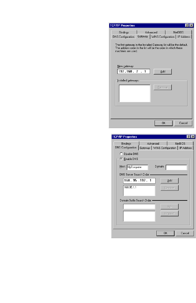
2. In the Gateway tab, add the
IP address of the Router
(default: 192.168.2.1)
in the
New gateway field and click
Add.
3. On the DNS Configuration
tab, add the IP address for
the Router and click Add.
This automatically relays
DNS requests to the DNS
server(s) provided by your
ISP. Otherwise, add specific
DNS servers into the DNS
Server Search Order field
and click Add
.
4. After finishing TCP/IP setup,
click OK, and then reboot
the computer. After that, set
up other PCs on the LAN
according to the procedures described above.

Setting Up TCP/IP
25
Verifying Your TCP/IP Connection
After installing the TCP/IP communication protocols and
configuring an IP address in the same network as the Router,
use the Ping command to check if your computer has
successfully connected to the Router. The following example
shows how the Ping procedure can be executed in an MS-DOS
window. First, execute the Ping command:
ping 192.168.2.1
If a message similar to the following appears:
Pinging 192.168.2.1 with 32 bytes of data:
Reply from 192.168.2.1: bytes=32 time=2ms TTL=64
a communication link between your computer and the Router has
been successfully established.
If you get the following message,
Pinging 192.168.2.1 with 32 bytes of data:
Request timed out.
there may be something wrong in your installation procedure.
Check the following items in sequence:
1. Is the Ethernet cable correctly connected between the Router
and the computer?
The LAN LED on the Router and the Link LED of the network
card on your computer must be on.
2. Is TCP/IP properly configured on your computer?
If the IP address of the Router is 192.168.2.1, the IP address
of your PC must be from 192.168.2.2 - 192.168.2.254 and
the default gateway must be 192.168.2.1.
If you can successfully Ping the Router you are now ready to
connect to the Internet!

26
C
ONFIGURING
THE
W
IRELESS
B
ARRICADE
G
R
OUTER
The Wireless Barricade g Router can be configured by Internet
Explorer 4.0 or above. Using the web management interface, you
can configure the Router and view statistics to monitor network
activity.
Note: Before you attempt to configure your router, if you have
access to the Internet please visit www.smc.com and
download the latest firmware update to ensure your
Router is running the latest firmware.
Before you attempt to log into the web-based Administration,
please verify the following.
1. Your browser is configured properly (see below).
2. Disable any firewall or security software that may be running.
3. Confirm that you have a good link LED where your computer
is plugged into the Router. If you don’t have a link light, then
try another cable until you get a good link.
Browser Configuration
Confirm your browser is configured for a direct connection to the
Internet using the Ethernet cable that is installed in the computer.
This is configured through the options/preference section of your
browser.

Browser Configuration
27
Disable Proxy Connection
You will also need to verify that the HTTP Proxy feature of your
web browser is disabled. This is so that your web browser will be
able to view the Router configuration pages. The following steps
are for Internet Explorer.
Internet Explorer 5 or above (For Windows)
1. Open Internet Explorer. Click Tools, and then select Internet
Options.
2. In the Internet Options window, click the Connections tab.
3. Click the LAN Settings button.
4. Clear all the check boxes and click OK to save these LAN
settings changes.
5. Click OK again to close the Internet Options window.
Internet Explorer (For Macintosh)
1. Open Internet Explorer. Click Explorer/Preferences.
2. In the Internet Explorer Preferences window, under Network,
select Proxies.
3. Uncheck all check boxes and click OK.
Configuring the Wireless Barricade g Router
28
Navigating the Web Browser Interface
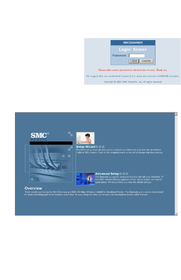
To access the Router’s
management interface,
enter the Router IP
address in your web
browser http://192.168.2.1
Then click LOGIN.
(By default, there is no
password.)
The home page displays the Setup Wizard and Advanced Setup
options.

Navigating the Web Browser Interface
29
The Router’s management interface features a Setup Wizard and
an Advanced Setup section. Use the Setup Wizard if you want to
quickly set up the Router for use with a cable modem or DSL
modem.
Advanced setup supports more advanced functions like hacker
attack detection, IP and MAC address filtering, intrusion
detection, virtual server setup, virtual DMZ hosts, and other
advanced functions.
Making Configuration Changes
Configurable parameters have a dialog box or a drop-down list.
Once a configuration change has been made on a page, be sure
to click the APPLY or NEXT button at the bottom of the page to
enable the new setting.
Note: To ensure proper screen refresh after a command
entry, ensure that Internet Explorer 5.0 is configured as
follows: Under the menu Tools/Internet Options/
General/Temporary Internet Files/Settings, the setting
for “Check for newer versions of stored pages” should
be “Every visit to the page.”
Configuring the Wireless Barricade g Router
30
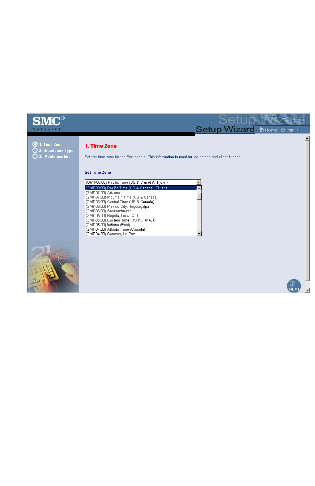
Setup Wizard
Time Zone
Click on the Setup Wizard picture. The first item in the Setup
Wizard is Time Zone setup.
For accurate timing of client filtering and log events, you need to
set the time zone. Select your time zone from the drop-down list,
and click NEXT.
Setup Wizard
31
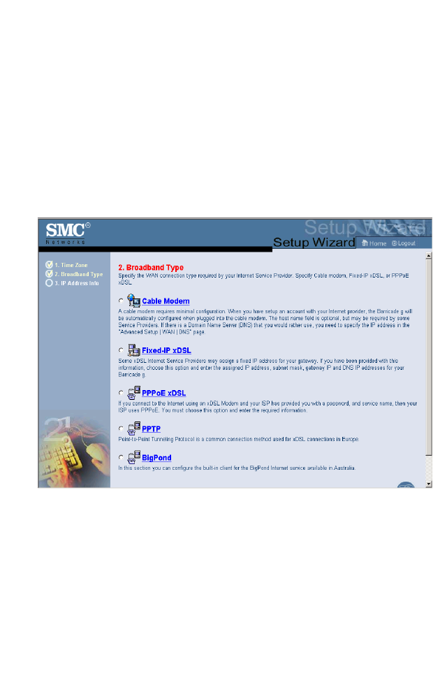
Broadband Type
Select the type of broadband connection you have.
For a cable modem connection see the following page. For a
Fixed-IP xDSL connection see “Fixed-IP xDSL” on page 32, for a
PPPoE xDSL connection, see “PPPoE xDSL” on page 33, for a
PPTP connection, see “Point-to-Point Tunneling Protocol
(PPTP)” on page 34, and for BigPond connection, see “BigPond”
on page 35.
Configuring the Wireless Barricade g Router
32
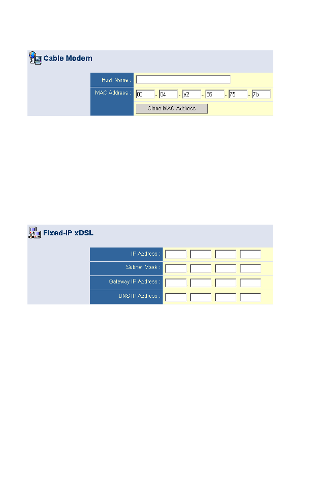
Cable Modem
Your Internet Service Provider may have given you a host name.
If so, enter it into the field.
Click Finish to complete the setup. The Status page will open to
allow you to view the connection status, as well as other
information. See “Status” on page 68 for details.
Fixed-IP xDSL
Some xDSL Internet Service Providers may assign a fixed
(static) IP address. If you have been provided with this
information, choose this option and enter the assigned IP
address, gateway IP address, DNS IP addresses, and subnet
mask. Click FINISH to complete the setup.
Setup Wizard
33
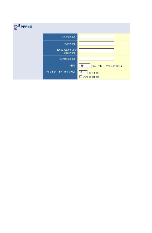
PPPoE xDSL
Enter the PPPoE User Name and Password assigned by your
Service Provider. The Service Name is normally optional, but
may be required by some service providers.
Leave the Maximum Transmission Unit (MTU) at the default
value (1454) unless you have a particular reason to change it.
Enter a Maximum Idle Time (in minutes) to define a maximum
period of time for which the Internet connection is maintained
during inactivity. If the connection is inactive for longer than the
Maximum Idle Time, it will be dropped. (Default: 10)
Enable the Auto-reconnect option to automatically re-establish
the connection as soon as you attempt to access the Internet
again. Click FINISH to complete the setup.
Configuring the Wireless Barricade g Router
34
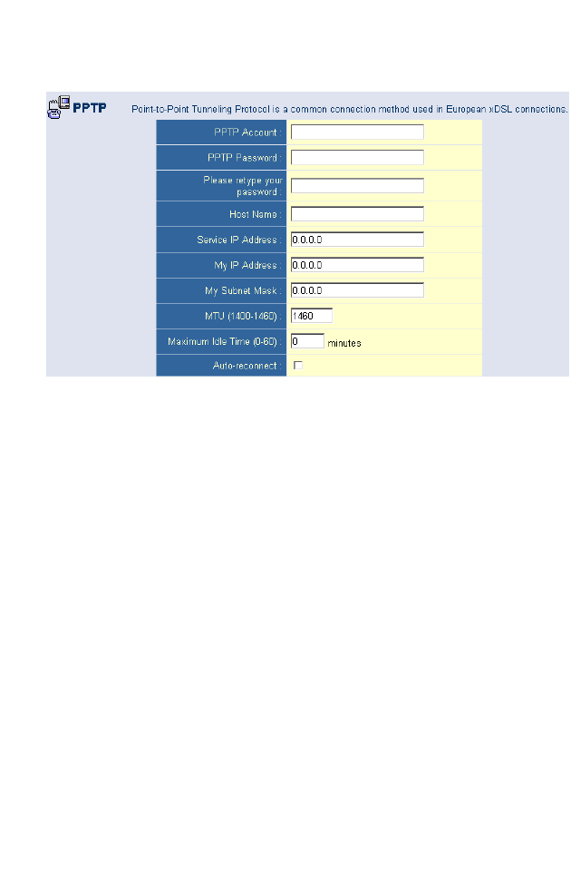
Point-to-Point Tunneling Protocol (PPTP)
Point-to-Point Tunneling Protocol is a common connection
method used for xDSL connections in Europe. It can be used to
join different physical networks using the Internet as an
intermediary.
If you have been provided with the information as shown on the
screen, enter the PPTP Account name and password, Host
Name, Service IP Address, the assigned IP address, and subnet
mask.
Leave the Maximum Transmission Unit (MTU) at the default
value (1460) unless you have a particular reason to change it.
Enter a Maximum Idle Time (in minutes) to define a maximum
period of time for which the Internet connection is maintained
during inactivity. If the connection is inactive for longer than the
Maximum Idle Time, it will be dropped. (Default: 10)
Enable the Auto-reconnect option to automatically re-establish
the connection as soon as you attempt to access the Internet
again. Click FINISH to complete the setup.
Advanced Setup
35
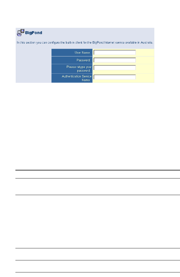
BigPond
If you use the BigPond Internet Service which is available in
Australia, enter the the user name, password and service name
for BigPond authentication. Click FINISH to complete the setup.
Advanced Setup
Use the web management interface to define system
parameters, manage and control the Router and its ports, or
monitor network conditions. The following table outlines the
selections available from this program.
Menu Description
System Sets the local time zone, the password for administrator access,
and the IP address of a PC that will be allowed to manage the
Router remotely.
WAN Specifies the Internet connection type:
•Dynamic IP host configuration and the physical MAC address
of each media interface
•PPPoE configuration
•PPTP configruation
•Static IP and ISP gateway address
•BigPond (Internet service available in Australia)
•Specifies DNS servers to use for domain name resolution.
LAN Sets the TCP/IP configuration of the Router’s LAN interface and
all DHCP clients.
NAT Shares a single ISP account with multiple users, sets up virtual
servers.

Configuring the Wireless Barricade g Router
36
Wireless Configures the radio frequency, SSID, encryption, and 802.1x
for wireless communications.
Firewall Configures a variety of security and specialized functions,
including: Access Control, Hacker Prevention, and DMZ.
DDNS Dynamic DNS provides users on the Internet with a method to
tie their domain name to a computer or server.
UPnP With Universal Plug and Play, a device can automatically and
dynamically join a network, obtain an IP address, communicate
its capabilities, and learn about the presence and capabilities of
other devices. Devices can then directly communicate with each
other. This further enables peer-to-peer networking.
Tools Contains options to back up & restore the current configuration,
restore all configuration settings to the factory defaults, update
system firmware, or reset the system.
Status Provides WAN connection type and status, firmware and
hardware version numbers, system IP settings, as well as
DHCP, NAT, and Firewall information.
Displays the number of attached clients, the firmware versions,
the physical MAC address for each media interface, and the
hardware version and serial number.
Shows the security and DHCP client log.
Menu Description
Advanced Setup
37
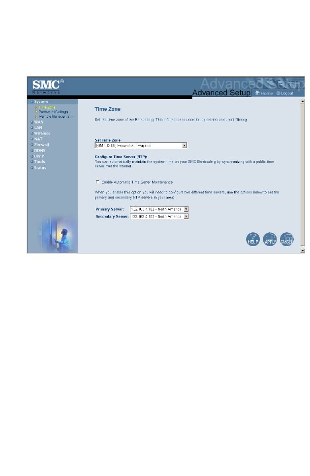
System
Time Zone
Set the time zone and time server for the Router. This
information is used for log entries and client access control.
Check Enable Automatic Time Server Maintenance to
automatically maintain the Router’s system time by synchronizing
with a public time server over the Internet. Then configure two
different time servers by selecting the options in the Primary
Server and Secondary Server fields.
Configuring the Wireless Barricade g Router
38
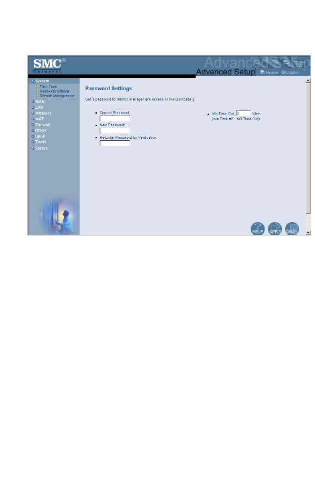
Password Settings
Use this menu to restrict access based on a password. By
default, there is no password. For security you should assign one
before exposing the Router to the Internet.
Passwords can contain from 3–12 alphanumeric characters and
are not case sensitive.
Advanced Setup
39
Note: If your password is lost, or you cannot gain access to
the user interface, press the Reset button on the rear
panel (holding it down for at least five seconds) to
restore the factory defaults. (The default is no
password.)
Enter a maximum Idle Time Out (in minutes) to define a
maximum period of time for which the login session is maintained
during inactivity. If the connection is inactive for longer than the
maximum idle time, it will perform system logout, and you have to
log into the web management system again.
(Default: 10 minutes)
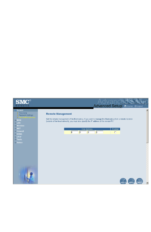
Remote Management
Remote Management allows a remote PC to configure, manage,
and monitor the Router using a standard web browser. Check
Enable and enter the IP address of the remote host. Click
APPLY.
Note: If you specify 0.0.0.0 as this IP address, any host can
manage the Router.

Configuring the Wireless Barricade g Router
40
WAN
Specify the WAN connection type provided by your Internet
Service Provider, then click More Configuration to enter detailed
configuration parameters for the selected connection type.
Dynamic IP
The Host Name is optional, but may be required by some ISPs.
The default MAC address is set to the WAN’s physical interface
on the Router. Use this address when registering for Internet
service, and do not change it unless required by your ISP. If your
ISP used the MAC address of an Ethernet card as an identifier
when first setting up your broadband account, only connect the
PC with the registered MAC address to the Router and click the
Clone MAC Address button. This will replace the current Router
MAC address with the already registered Ethernet card MAC
address.
If you are unsure of which PC was originally set up by the
broadband technician, call your ISP and request that they