Accton Technology 7404WBRAACC Wireless ADSL Barricade, Wireless ADSL Router User Manual 00 us
Accton Technology Corp Wireless ADSL Barricade, Wireless ADSL Router 00 us
Contents
- 1. User Manual Part 1
- 2. User Manual Part 2
- 3. User Manual Part 3
- 4. User Manual Part 4
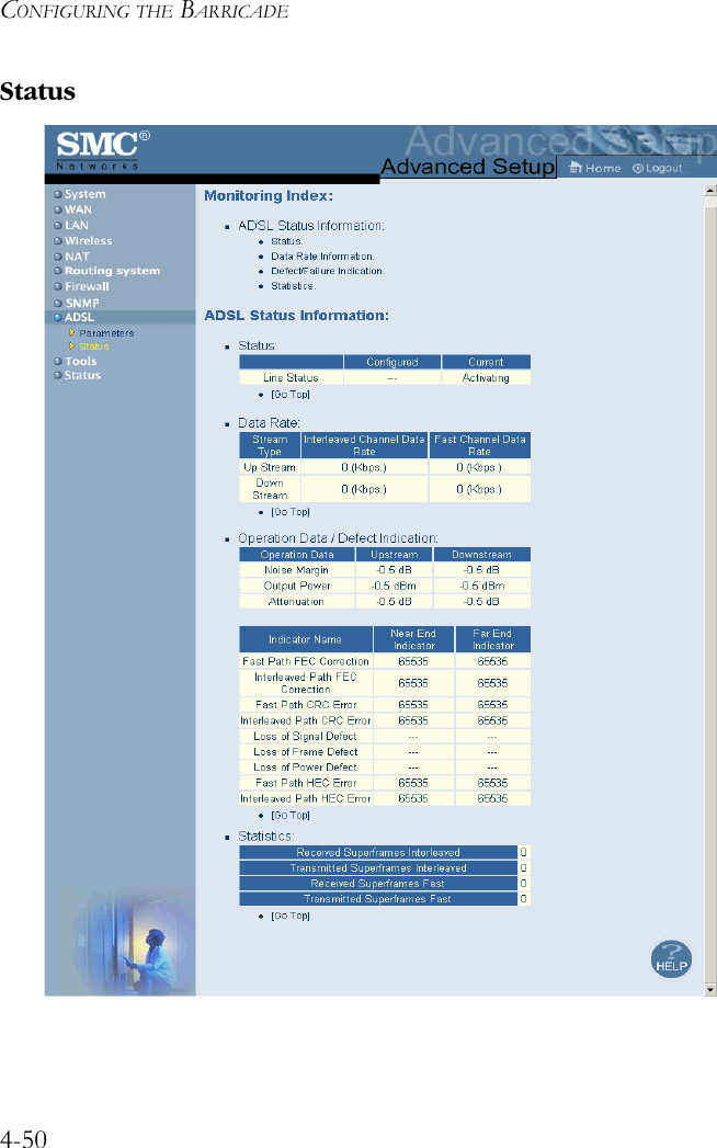
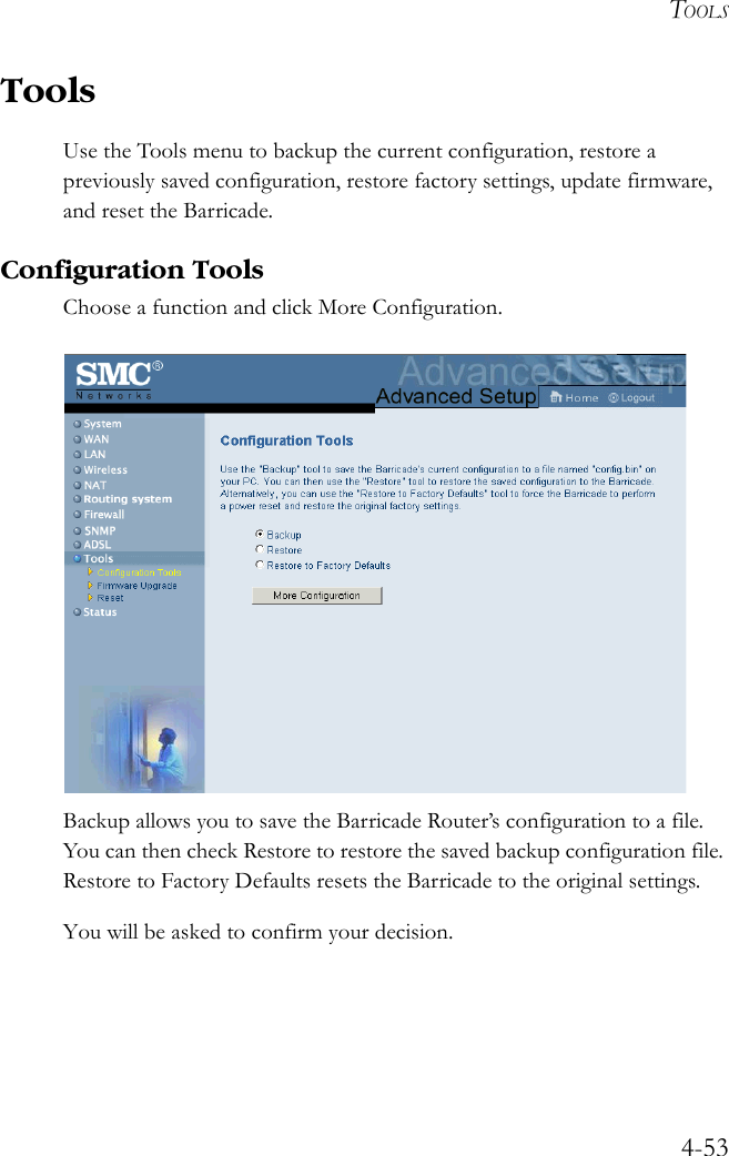
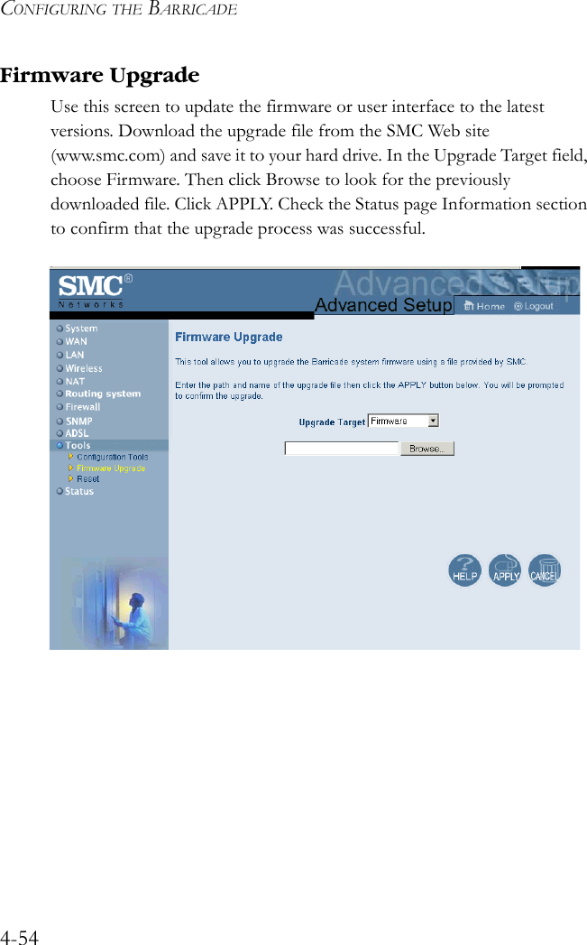
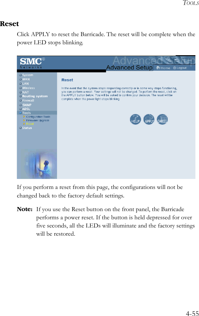
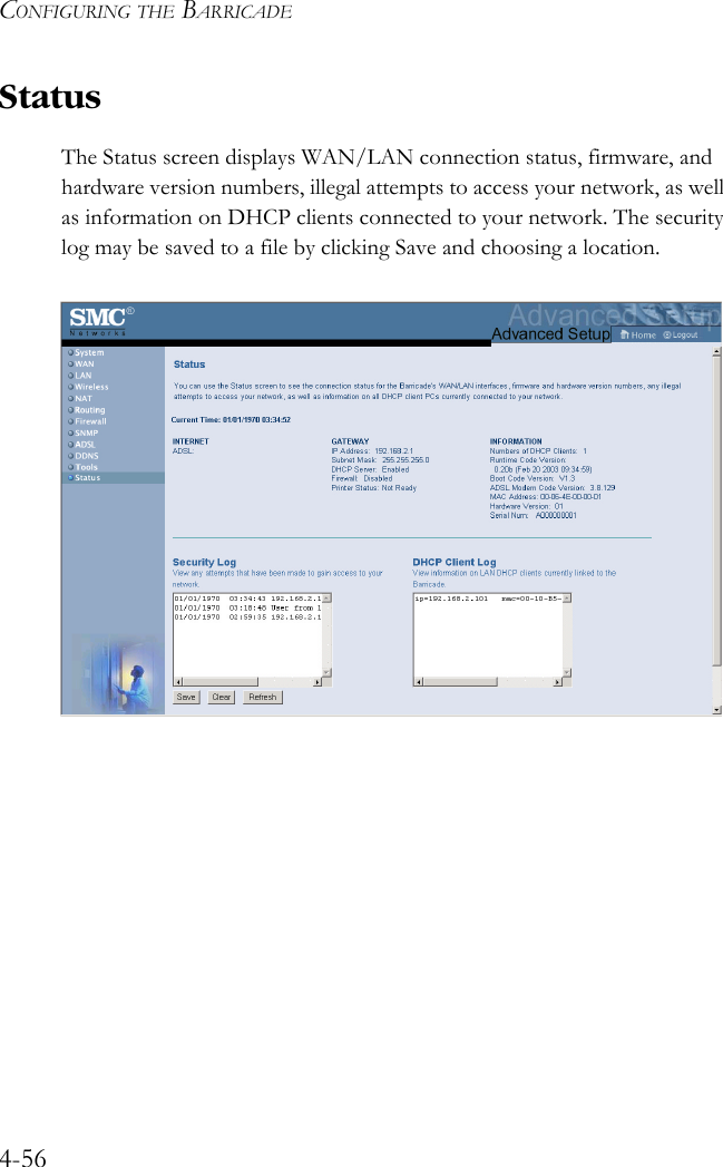
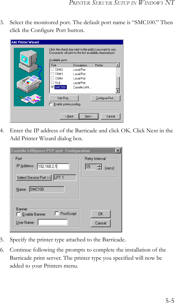
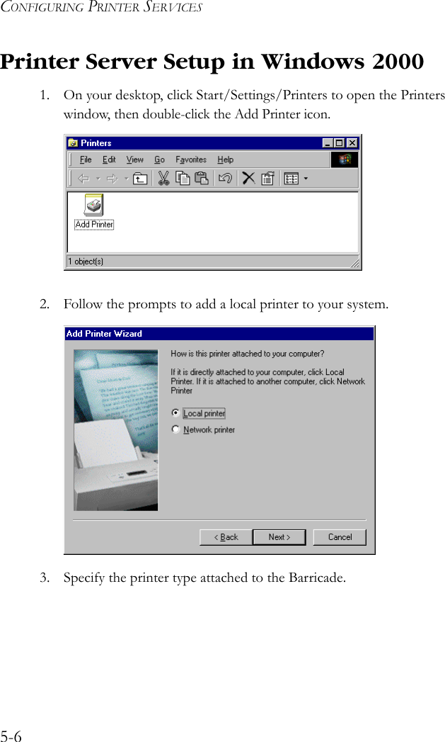
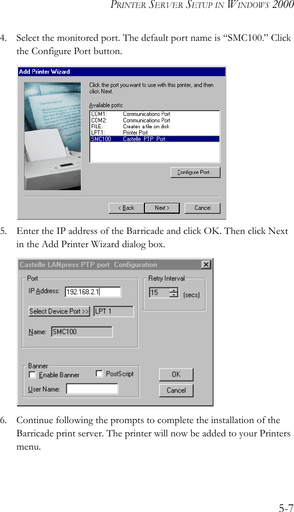
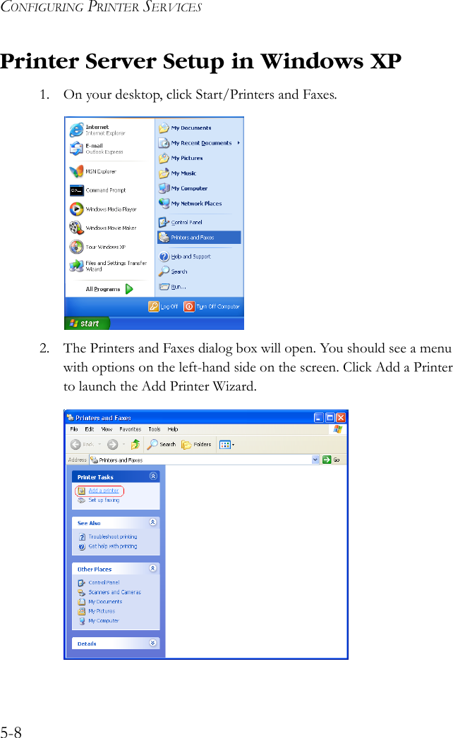
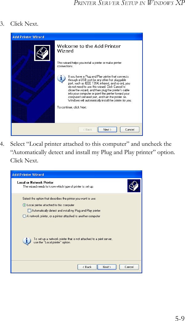
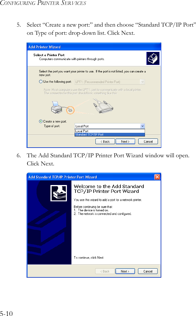
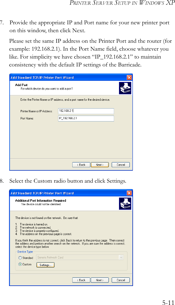
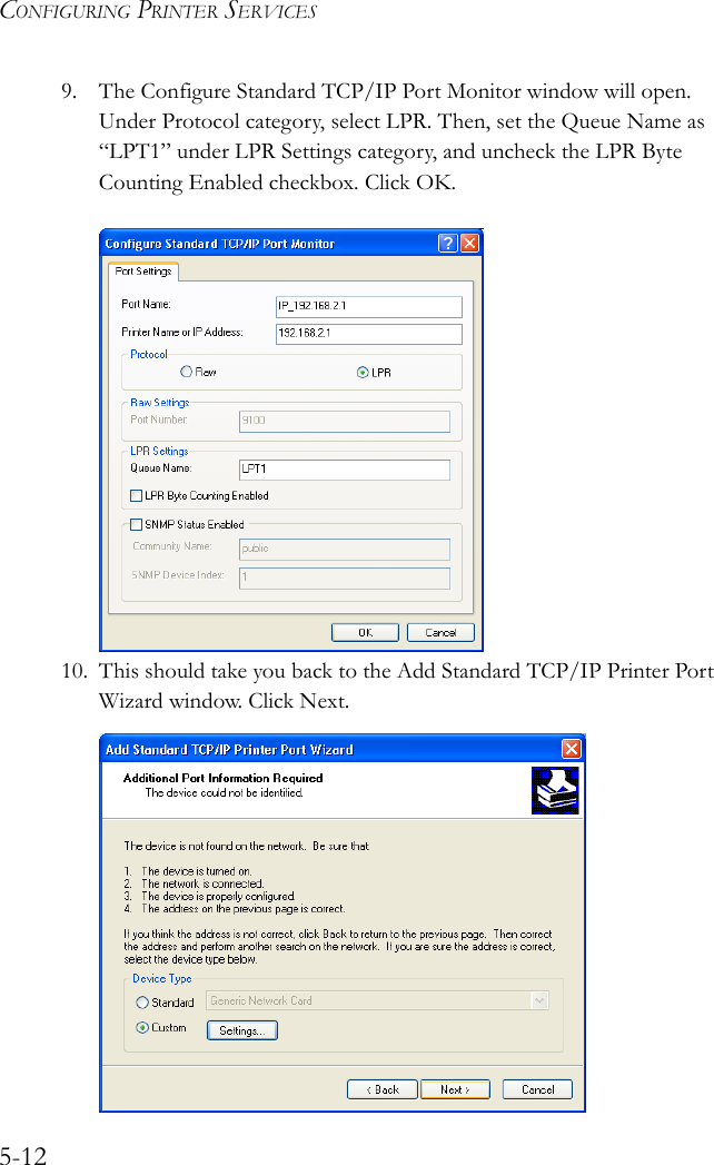
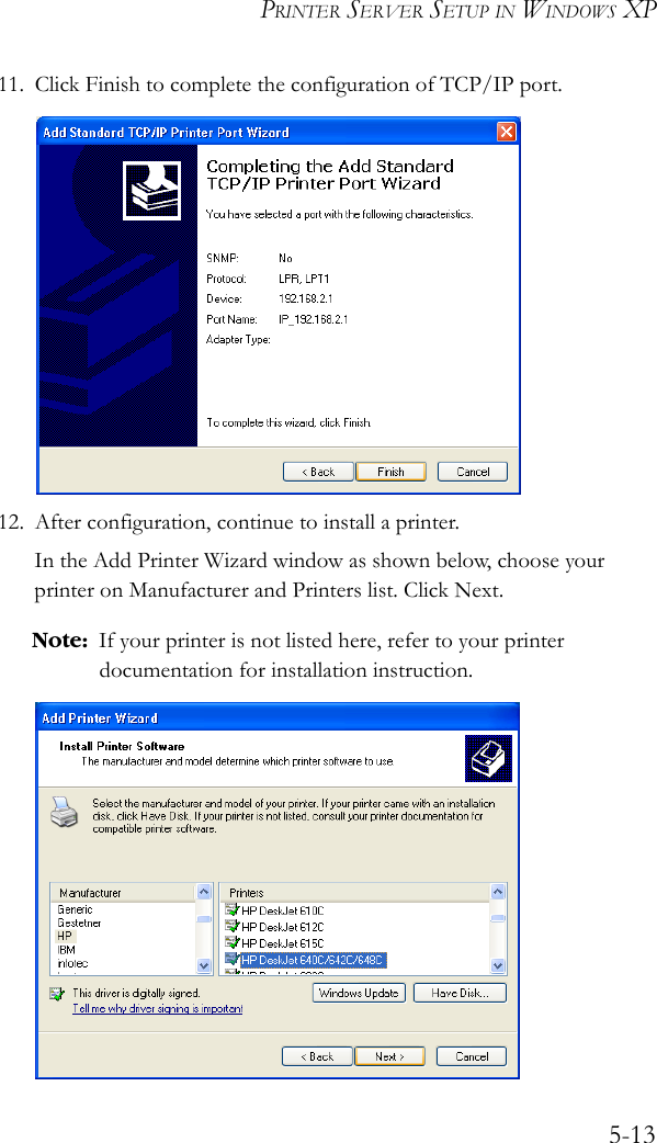
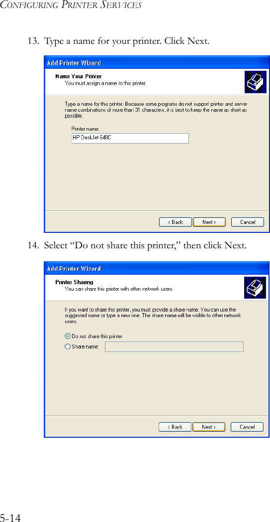
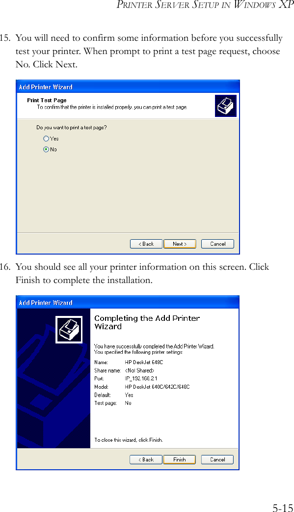
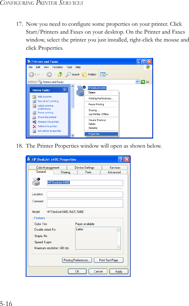
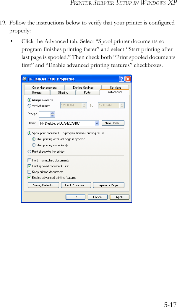
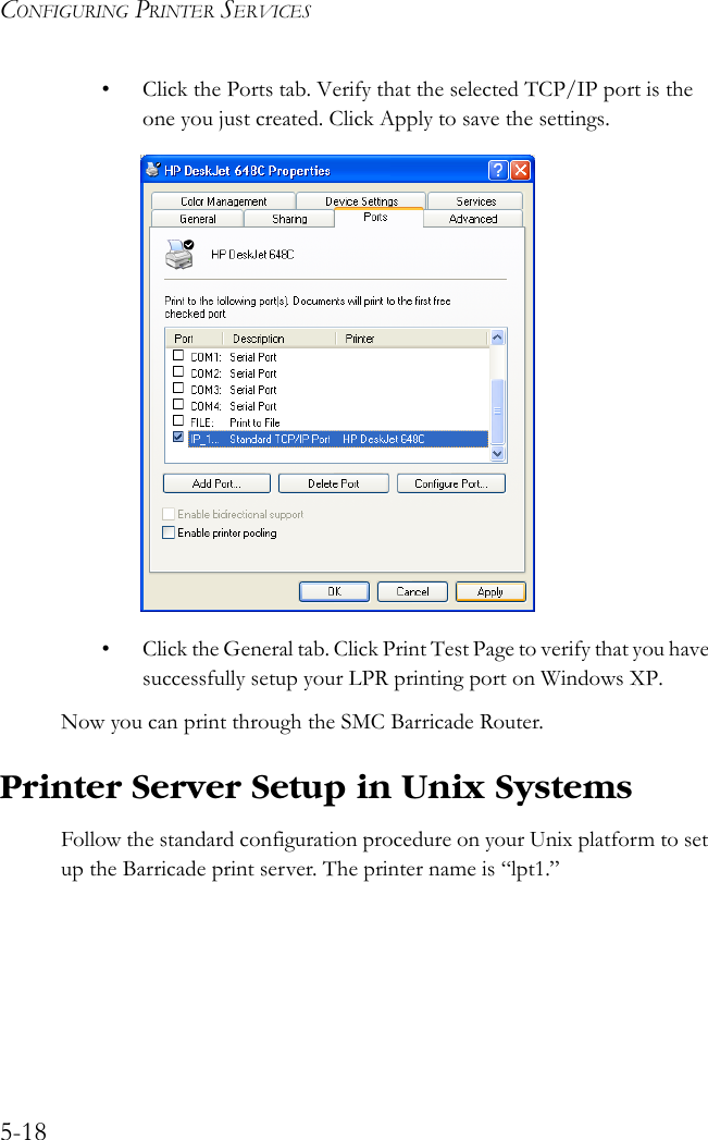
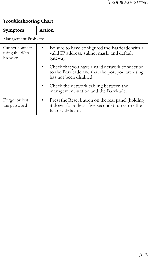
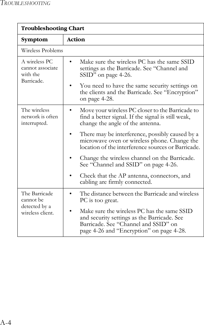
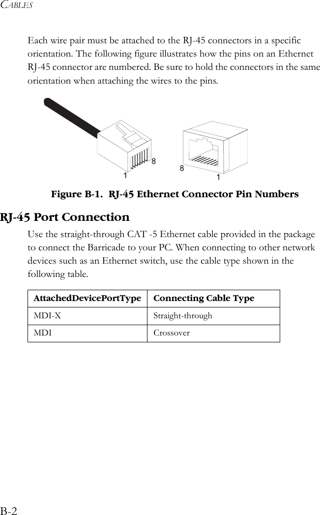
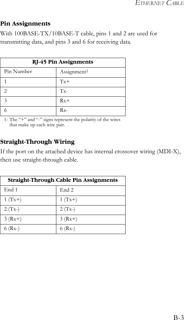
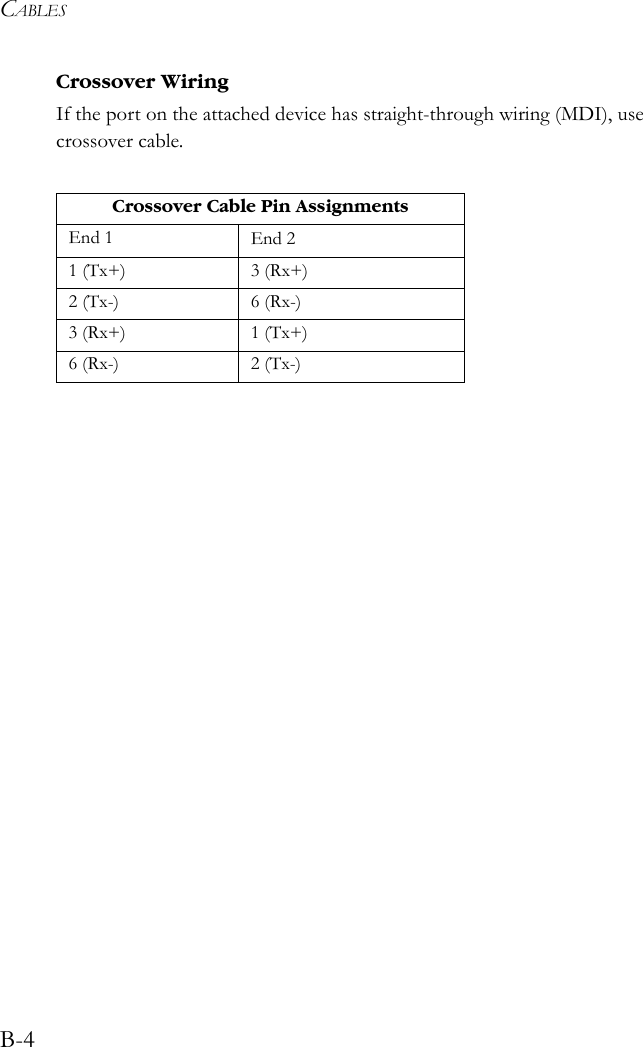
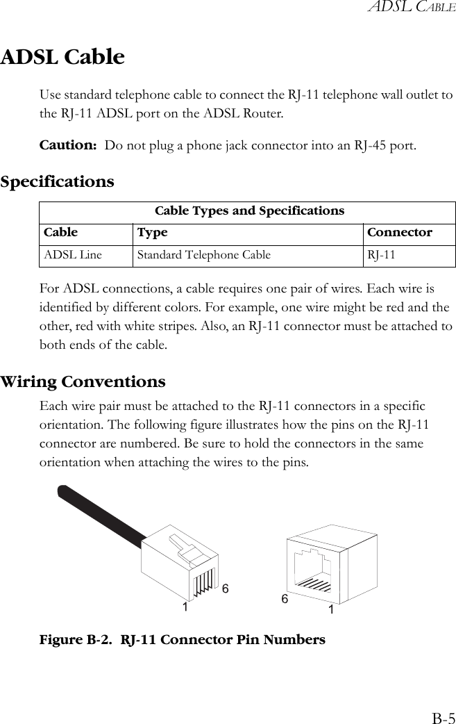
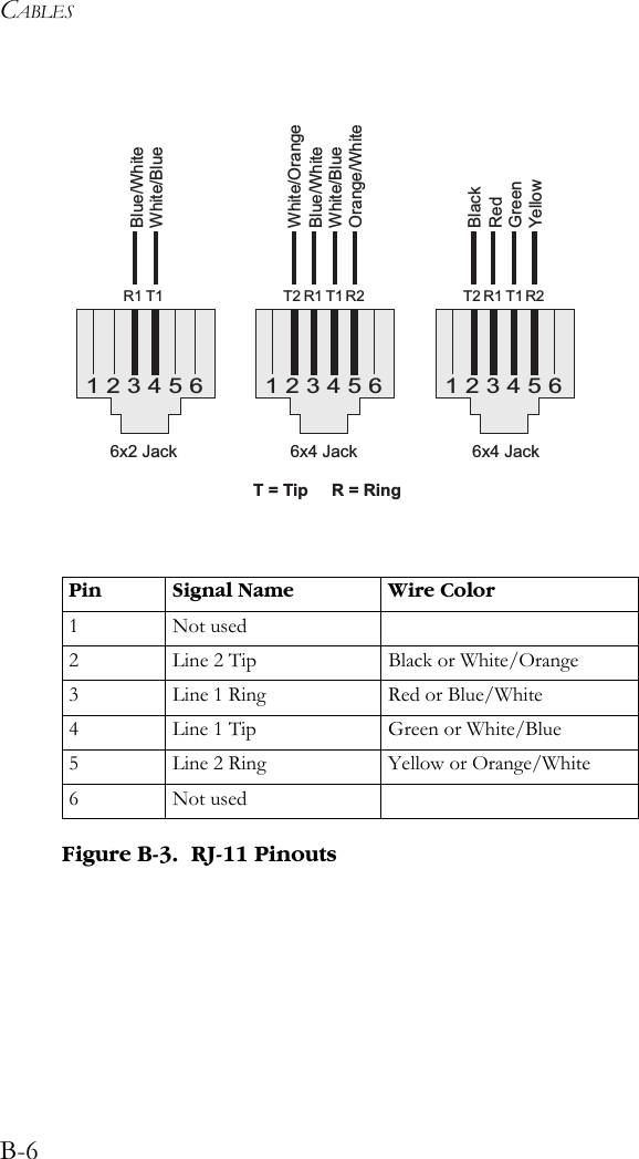
User Manual Part 4