Accton Technology 7404WBRAACC Wireless ADSL Barricade, Wireless ADSL Router User Manual 00 us
Accton Technology Corp Wireless ADSL Barricade, Wireless ADSL Router 00 us
Contents
- 1. User Manual Part 1
- 2. User Manual Part 2
- 3. User Manual Part 3
- 4. User Manual Part 4
User Manual Part 4
C
ONFIGURING
THE
B
ARRICADE
4-50
Status

ADSL
4-51
Parameter Description
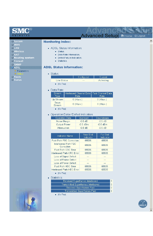
Status
Line Status Shows the current status of the ADSL line.
Data Rate
Upstream Maximum data rate upstream.
Downstream Maximum data rate downstream.
Operation
Data/Defect
Indication
Noise Margin
Upstream Minimum noise margin upstream.
Downstream Minimum noise margin downstream.
Output Power Maximum fluctuation in the output power.
Attenuation
Upstream Maximum reduction in the strength of the upstream signal.
Downstream Maximum reduction in the strength of the downstream signal.
Fast Path FEC
Correction There are two latency paths that may be used: fast and
interleaved. For either path a forward error correction (FEC)
scheme is employed to ensure higher data integrity. For
maximum noise immunity, an interleaver may be used to
supplement FEC.
Interleaved Path
FEC Correction An interleaver is basically a buffer used to introduce a delay,
allowing for additional error correction techniques to handle
noise. Interleaving slows the data flow and may not be
optimal for real-time signals such as video transmission.
Fast Path CRC
Error Indicates the number of Fast Path Cyclic Redundancy Check
errors.
Interleaved Path
CRC Error Indicates the number of Interleaved Path Cyclic Redundancy
Check errors.
Loss of Signal
Defect Momentary signal discontinuities.
Loss of Frame
Defect Failures due to loss of frames.

C
ONFIGURING
THE
B
ARRICADE
4-52
Loss of Power
Defect Failures due to loss of power.
Fast Path HEC
Error Fast Path Header Error Concealment errors.
Interleaved Path
HEC Error Interleaved Path Header Error Concealment errors.
Statistics (Superframes represent the highest level of data presentation.
Each superframe contains regular ADSL frames, one of
which is used to provide superframe synchronization,
identifying the start of a superframe. Some of the remaining
frames are also used for special functions.)
Received
Superframes
Interleaved
Number of interleaved superframes received.
Transmitted
Superframes
Interleaved
Number of interleaved superframes transmitted.
Received
Superframes Fast Number of fast superframes received.
Transmitted
Superframes Fast Number of fast superframes transmitted.
Parameter Description
T
OOLS
4-53
Tools
Use the Tools menu to backup the current configuration, restore a
previously saved configuration, restore factory settings, update firmware,
and reset the Barricade.
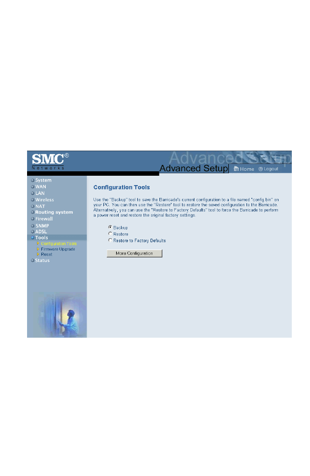
Configuration Tools
Choose a function and click More Configuration.
Backup allows you to save the Barricade Router’s configuration to a file.
You can then check Restore to restore the saved backup configuration file.
Restore to Factory Defaults resets the Barricade to the original settings.
You will be asked to confirm your decision.
C
ONFIGURING
THE
B
ARRICADE
4-54
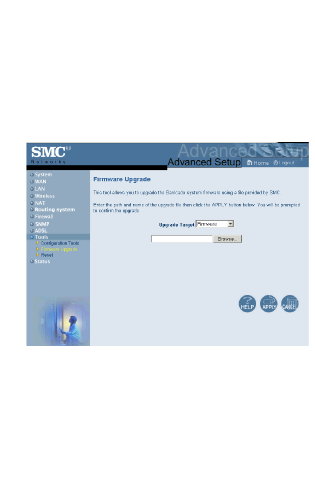
Firmware Upgrade
Use this screen to update the firmware or user interface to the latest
versions. Download the upgrade file from the SMC Web site
(www.smc.com) and save it to your hard drive. In the Upgrade Target field,
choose Firmware. Then click Browse to look for the previously
downloaded file. Click APPLY. Check the Status page Information section
to confirm that the upgrade process was successful.
T
OOLS
4-55
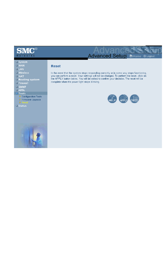
Reset
Click APPLY to reset the Barricade. The reset will be complete when the
power LED stops blinking.
If you perform a reset from this page, the configurations will not be
changed back to the factory default settings.
Note: If you use the Reset button on the front panel, the Barricade
performs a power reset. If the button is held depressed for over
five seconds, all the LEDs will illuminate and the factory settings
will be restored.
C
ONFIGURING
THE
B
ARRICADE
4-56
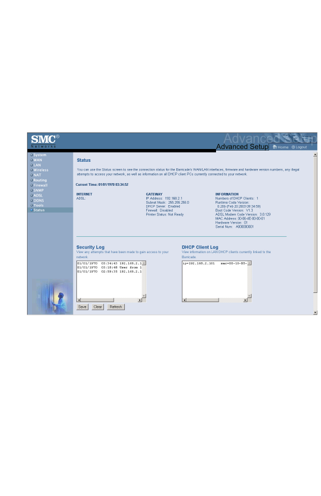
Status
The Status screen displays WAN/LAN connection status, firmware, and
hardware version numbers, illegal attempts to access your network, as well
as information on DHCP clients connected to your network. The security
log may be saved to a file by clicking Save and choosing a location.

F
INDING
THE
MAC
ADDRESS
OF
A
N
ETWORK
C
ARD
4-57
The following items are included on the Status screen:
Finding the MAC address of a Network
Card
Windows 95/98/ME
Click Start/Run. Type “winipcfg” and press ENTER.
The MAC address is in the “Adapter Address” section.
Windows NT4/2000/XP
Click Start/Programs/Command Prompt. Type “ipconfig /all” and press
ENTER.
The MAC address is listed as the “Physical Address.”
Linux
Run the command “/sbin/ifconfig.”
The MAC address is the value after the word “HWaddr.”
Parameter Description
INTERNET Displays WAN connection type and status.
GATEWAY Displays system IP settings, as well as DHCP
Server and Firewall status.
INFORMATION Displays the number of attached clients, the
firmware versions, the physical MAC address for
each media interface, and for the Barricade, as well
as the hardware version and serial number.
Security Log Displays illegal attempts to access your network.
DHCP Client Log Displays information on DHCP clients on your
network.

C
ONFIGURING
THE
B
ARRICADE
4-58

5-1
C
HAPTER
5
C
ONFIGURING
P
RINTER
S
ERVICES
To use the print server built into the Barricade, you must first install the
Port Monitor program as described in the following section for
Windows 95/98/Me.
To set up the Barricade Print Server for Windows NT, see “Printer Server
Setup in Windows NT” on page 5-4. For Windows 2000, see “Printer
Server Setup in Windows 2000” on page 5-6. For Windows XP, see
“Printer Server Setup in Windows XP” on page 5-8. For Unix Systems,
see “Printer Server Setup in Unix Systems” on page 5-18.
Printer Server Setup in Windows 95/98/
Me
You may find that the instructions here do not exactly match your version
of Windows. This is because these steps and screenshots were created in
Windows 98. Windows 95 and Windows Millennium Edition are very
similar, but not identical, to Windows 98.
1. Insert the installation CD-ROM into your CD-ROM drive. Under the
PrintSvr directory, run the “setup.exe” program. The Port Monitor
installation program advises you to close all other Windows programs
currently running on your computer. Click Next to continue.
C
ONFIGURING
P
RINTER
S
ERVICES
5-2
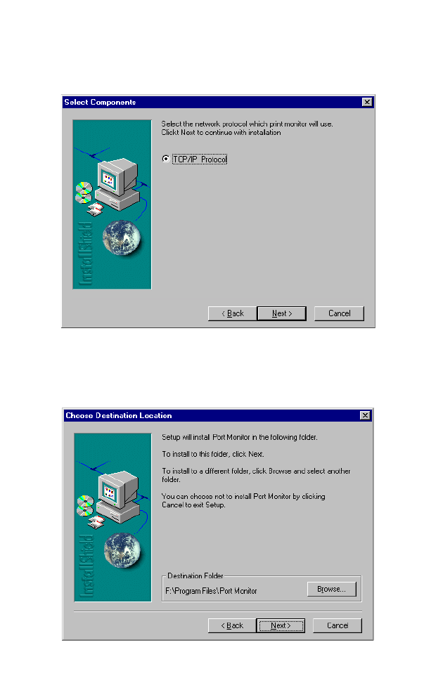
2. The next screen indicates that the print client uses the TCP/IP
network protocol to monitor print requests. Click Next.
3. Select the destination folder and click on the Next button. The setup
program will then begin to install the programs into the destination
folder.
P
RINTER
S
ERVER
S
ETUP
IN
W
INDOWS
95/98/M
E
5-3
4. Select the Program Folder that will contain the program icon for
uninstalling the port monitor, and then click Next.
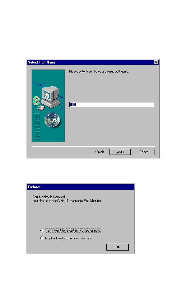
5. Enter the printer port name that will be used to identify the port
monitor in your system, and click Next.
6. When the setup program finishes installing the port monitor, choose
“Yes, I want to restart my computer now” and then click OK.
C
ONFIGURING
P
RINTER
S
ERVICES
5-4
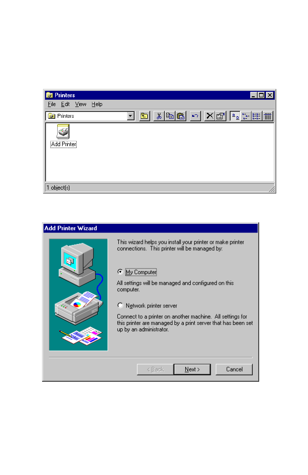
Printer Server Setup in Windows NT
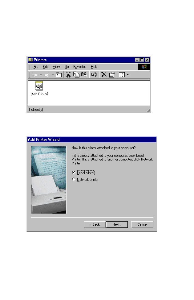
1. On a Windows NT platform, open the Printers window in
the My
Computer menu, and double-click the Add Printer icon.
2. Follow the prompts to add a local printer to your system.
P
RINTER
S
ERVER
S
ETUP
IN
W
INDOWS
NT
5-5
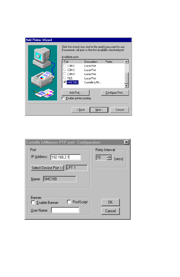
3. Select the monitored port. The default port name is “SMC100.” Then
click the Configure Port button.
4. Enter the IP address of the Barricade and click OK. Click Next in the
Add Printer Wizard dialog box.
5. Specify the printer type attached to the Barricade.
6. Continue following the prompts to complete the installation of the
Barricade print server. The printer type you specified will now be
added to your Printers menu.
C
ONFIGURING
P
RINTER
S
ERVICES
5-6
Printer Server Setup in Windows 2000
1. On your desktop, click Start/Settings/Printers to open the Printers
window, t
hen double-click the Add Printer icon.
2. Follow the prompts to add a local printer to your system.
3. Specify the printer type attached to the Barricade.
P
RINTER
S
ERVER
S
ETUP
IN
W
INDOWS
2000
5-7
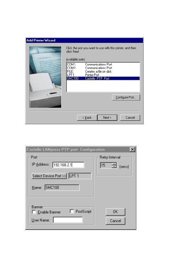
4. Select the monitored port. The default port name is “SMC100.” Click
the Configure Port button.
5. Enter the IP address of the Barricade and click OK. Then click Next
in the Add Printer Wizard dialog box.
6. Continue following the prompts to complete the installation of the
Barricade print server. The printer will now be added to your Printers
menu.
C
ONFIGURING
P
RINTER
S
ERVICES
5-8
Printer Server Setup in Windows XP
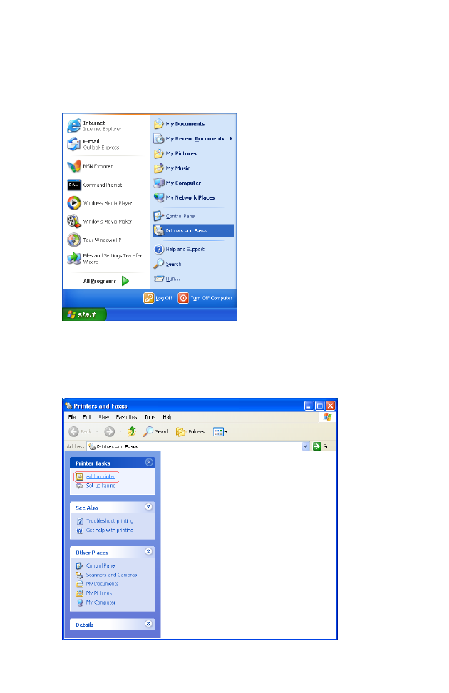
1. On your desktop, click Start/Printers and Faxes.
2. The Printers and Faxes dialog box will open. You should see a menu
with options on the left-hand side on the screen. Click Add a Printer
to launch the Add Printer Wizard.
P
RINTER
S
ERVER
S
ETUP
IN
W
INDOWS
XP
5-9
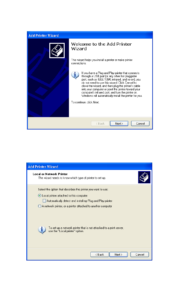
3. Click Next.
4. Select “Local printer attached to this computer” and uncheck the
“Automatically detect and install my Plug and Play printer” option.
Click Next.
C
ONFIGURING
P
RINTER
S
ERVICES
5-10
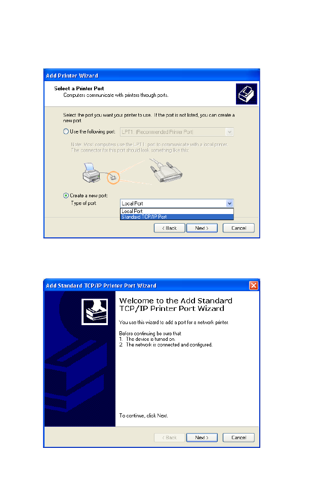
5. Select “Create a new port:” and then choose “Standard TCP/IP Port”
on Type of port: drop-down list. Click Next.
6. The Add Standard TCP/IP Printer Port Wizard window will open.
Click Next.
P
RINTER
S
ERVER
S
ETUP
IN
W
INDOWS
XP
5-11
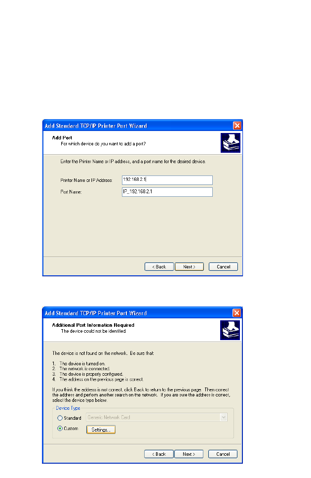
7. Provide the appropriate IP and Port name for your new printer port
on this window, then click Next.
Please set the same IP address on the Printer Port and the router (for
example: 192.168.2.1). In the Port Name field, choose whatever you
like. For simplicity we have chosen “IP_192.168.2.1” to maintain
consistency with the default IP settings of the Barricade.
8. Select the Custom radio button and click Settings.
C
ONFIGURING
P
RINTER
S
ERVICES
5-12
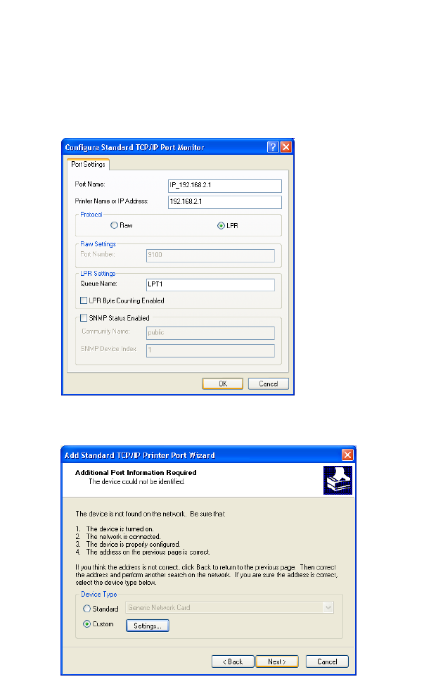
9. The Configure Standard TCP/IP Port Monitor window will open.
Under Protocol category, select LPR. Then, set the Queue Name as
“LPT1” under LPR Settings category, and uncheck the LPR Byte
Counting Enabled checkbox. Click OK.
10. This should take you back to the Add Standard TCP/IP Printer Port
Wizard window. Click Next.
P
RINTER
S
ERVER
S
ETUP
IN
W
INDOWS
XP
5-13
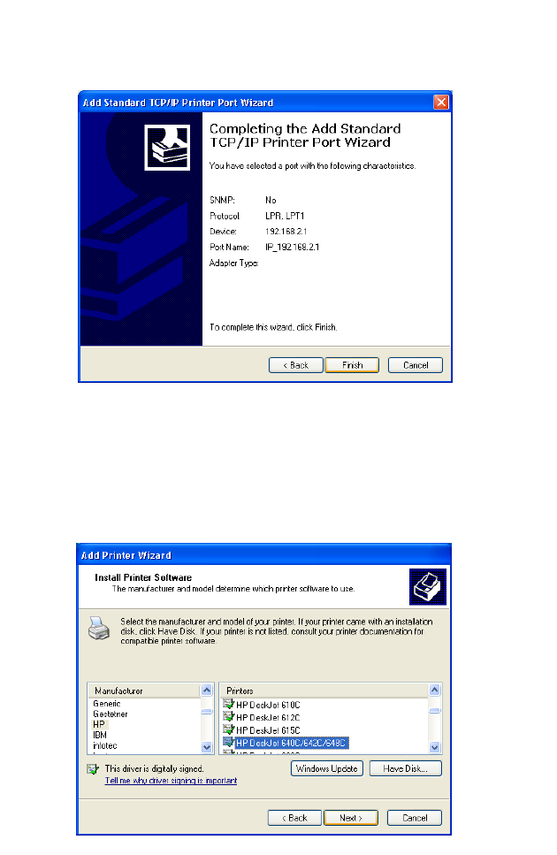
11. Click Finish to complete the configuration of TCP/IP port.
12. After configuration, continue to install a printer.
In the Add Printer Wizard window as shown below, choose your
printer on Manufacturer and Printers list. Click Next.
Note: If your printer is not listed here, refer to your printer
documentation for installation instruction.
C
ONFIGURING
P
RINTER
S
ERVICES
5-14
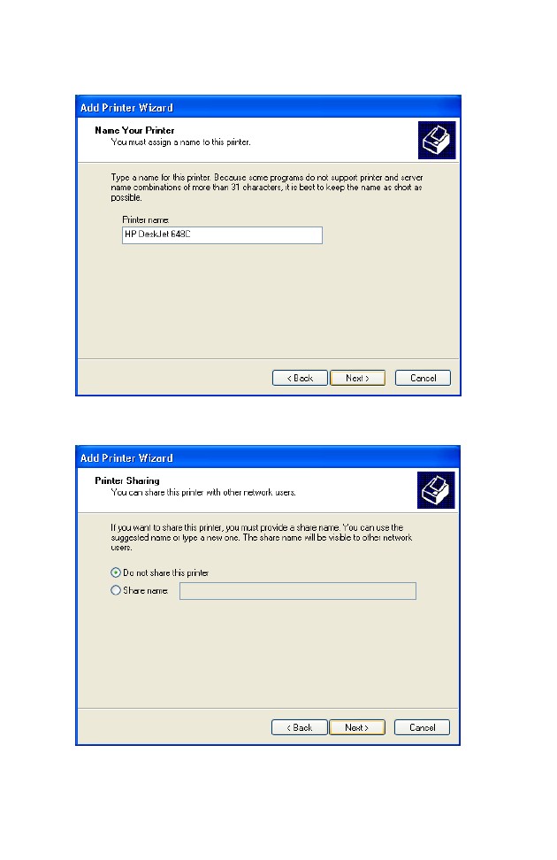
13. Type a name for your printer. Click Next.
14. Select “Do not share this printer,” then click Next.
P
RINTER
S
ERVER
S
ETUP
IN
W
INDOWS
XP
5-15
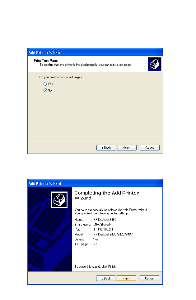
15. You will need to confirm some information before you successfully
test your printer. When prompt to print a test page request, choose
No. Click Next.
16. You should see all your printer information on this screen. Click
Finish to complete the installation.
C
ONFIGURING
P
RINTER
S
ERVICES
5-16
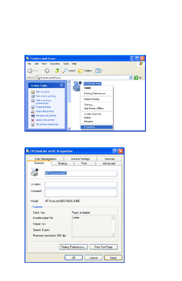
17. Now you need to configure some properties on your printer. Click
Start/Printers and Faxes on your desktop. On the Printer and Faxes
window, select the printer you just installed, right-click the mouse and
click Properties.
18. The Printer Properties window will open as shown below.
P
RINTER
S
ERVER
S
ETUP
IN
W
INDOWS
XP
5-17
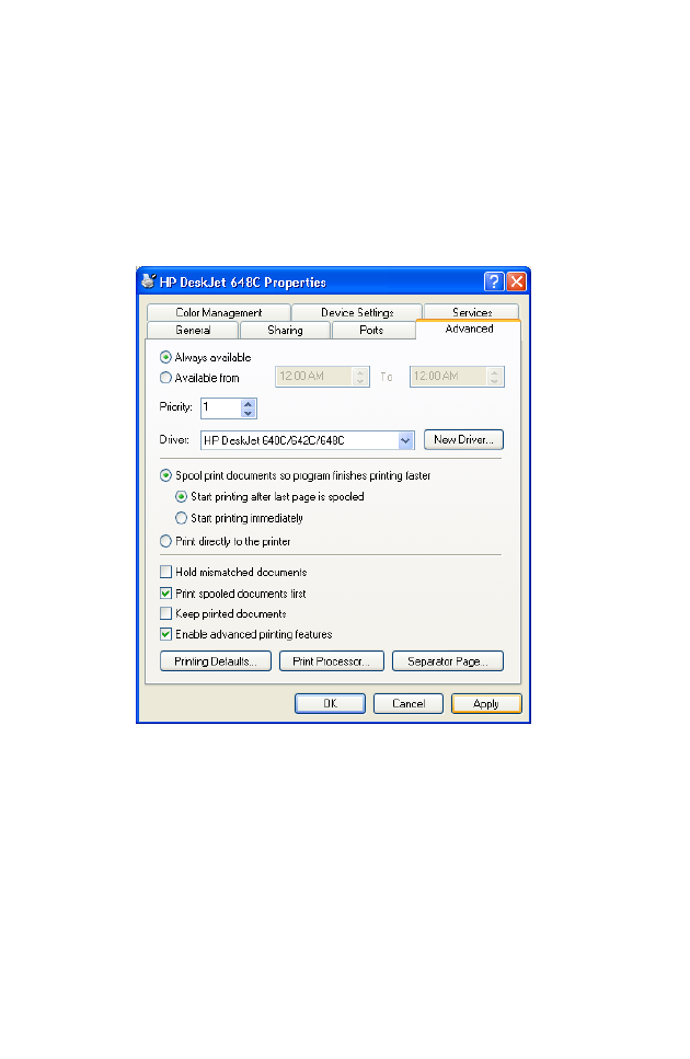
19. Follow the instructions below to verify that your printer is configured
properly:
• Click the Advanced tab. Select “Spool printer documents so
program finishes printing faster” and select “Start printing after
last page is spooled.” Then check both “Print spooled documents
first” and “Enable advanced printing features” checkboxes.
C
ONFIGURING
P
RINTER
S
ERVICES
5-18
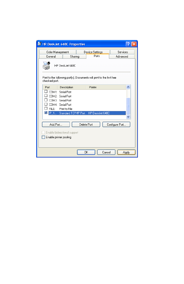
• Click the Ports tab. Verify that the selected TCP/IP port is the
one you just created. Click Apply to save the settings.
• Click the General tab. Click Print Test Page to verify that you have
successfully setup your LPR printing port on Windows XP.
Now you can print through the SMC Barricade Router.
Printer Server Setup in Unix Systems
Follow the standard configuration procedure on your Unix platform to set
up the Barricade print server. The printer name is “lpt1.”

A-1
C
HAPTER
A
T
ROUBLESHOOTING
This section describes common problems you may encounter and possible
solutions to them. The Barricade can be easily monitored through panel
indicators to identify problems.
Troubleshooting Chart
Symptom Action
LED Indicators
Power LED is
Off • Check connections between the Barricade, the
external power supply, and the wall outlet.
• If the power indicator does not turn on when the
power cord is plugged in, you may have a
problem with the power outlet, power cord, or
external power supply.
However, if the unit powers off after running for
a while, check for loose power connections,
power losses, or surges at the power outlet.
If you still cannot isolate the problem, then the
external power supply may be defective. In this
case, contact Technical Support for assistance.

T
ROUBLESHOOTING
A-2
LED Indicators
Link LED is Off • Verify that the Barricade and attached device are
powered on.
• Be sure the cable is plugged into both the
Barricade and the corresponding device.
• Verify that the proper cable type is used and that
its length does not exceed the specified limits.
• Be sure that the network interface on the
attached device is configured for the proper
communication speed and duplex mode.
• Check the adapter on the attached device and
cable connections for possible defects. Replace
any defective adapter or cable if necessary.
Network Connection Problems
Cannot Ping the
Barricade from
the attached
LAN, or the
Barricade cannot
Ping any device
on the attached
LAN
• Verify that the IP addresses are properly
configured. For most applications, you should
use the Barricade’s DHCP function to
dynamically assign IP addresses to hosts on the
attached LAN. However, if you manually
configure IP addresses on the LAN, verify that
the same network address (network component
of the IP address) and subnet mask are used for
both the Barricade and any attached LAN
devices.
• Be sure the device you want to ping (or from
which you are pinging) has been configured for
TCP/IP.
Troubleshooting Chart
Symptom Action

T
ROUBLESHOOTING
A-3
Management Problems
Cannot connect
using the Web
browser
• Be sure to have configured the Barricade with a
valid IP address, subnet mask, and default
gateway.
• Check that you have a valid network connection
to the Barricade and that the port you are using
has not been disabled.
• Check the network cabling between the
management station and the Barricade.
Forgot or lost
the password • Press the Reset button on the rear panel (holding
it down for at least five seconds) to restore the
factory defaults.
Troubleshooting Chart
Symptom Action

T
ROUBLESHOOTING
A-4
Wireless Problems
A wireless PC
cannot associate
with the
Barricade.
• Make sure the wireless PC has the same SSID
settings as the Barricade. See “Channel and
SSID” on page 4-26.
• You need to have the same security settings on
the clients and the Barricade. See “Encryption”
on page 4-28.
The wireless
network is often
interrupted.
• Move your wireless PC closer to the Barricade to
find a better signal. If the signal is still weak,
change the angle of the antenna.
• There may be interference, possibly caused by a
microwave oven or wireless phone. Change the
location of the interference sources or Barricade.
• Change the wireless channel on the Barricade.
See “Channel and SSID” on page 4-26.
• Check that the AP antenna, connectors, and
cabling are firmly connected.
The Barricade
cannot be
detected by a
wireless client.
• The distance between the Barricade and wireless
PC is too great.
• Make sure the wireless PC has the same SSID
and security settings as the Barricade. See
Barricade. See “Channel and SSID” on
page 4-26 and “Encryption” on page 4-28.
Troubleshooting Chart
Symptom Action

B-1
A
PPENDIX
B
C
ABLES
Ethernet Cable
Caution: DO NOT plug a phone jack connector into any RJ-45 port.
Use only twisted-pair cables with RJ-45 connectors that
conform with FCC standards.
Specifications
Wiring Conventions
For Ethernet connections, a twisted-pair cable must have two pairs of
wires. Each wire pair is identified by two different colors. For example, one
wire might be red and the other, red with white stripes. Also, an RJ-45
connector must be attached to both ends of the cable.
Cable Types and Specifications
Cable Type Max. Length Connector
10BASE-T Cat. 3, 4, 5 100-ohm UTP 100 m (328 ft) RJ-45
100BASE-TX Cat. 5 100-ohm UTP 100 m (328 ft) RJ-45
C
ABLES
B-2
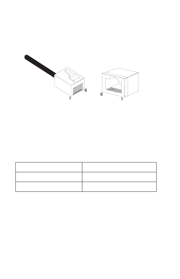
Each wire pair must be attached to the RJ-45 connectors in a specific
orientation. The following figure illustrates how the pins on an Ethernet
RJ-45 connector are numbered. Be sure to hold the connectors in the same
orientation when attaching the wires to the pins.
Figure B-1. RJ-45 Ethernet Connector Pin Numbers
RJ-45 Port Connection
Use the straight-through CAT -5 Ethernet cable provided in the package
to connect the Barricade to your PC. When connecting to other network
devices such as an Ethernet switch, use the cable type shown in the
following table.
Attached Device Port Type Connecting Cable Type
MDI-X Straight-through
MDI Crossover

E
THERNET
C
ABLE
B-3
Pin Assignments
With 100BASE-TX/10BASE-T cable, pins 1 and 2 are used for
transmitting data, and pins 3 and 6 for receiving data.
Straight-Through Wiring
If the port on the attached device has internal crossover wiring (MDI-X),
then use straight-through cable.
RJ-45 Pin Assignments
Pin Number Assignment1
1Tx+
2Tx-
3Rx+
6Rx-
1: The “+” and “-” signs represent the polarity of the wires
that make up each wire pair.
Straight-Through Cable Pin Assignments
End 1 End 2
1 (Tx+) 1 (Tx+)
2 (Tx-) 2 (Tx-)
3 (Rx+) 3 (Rx+)
6 (Rx-) 6 (Rx-)

C
ABLES
B-4
Crossover Wiring
If the port on the attached device has straight-through wiring (MDI), use
crossover cable.
Crossover Cable Pin Assignments
End 1 End 2
1 (Tx+) 3 (Rx+)
2 (Tx-) 6 (Rx-)
3 (Rx+) 1 (Tx+)
6 (Rx-) 2 (Tx-)
ADSL C
ABLE
B-5
ADSL Cable
Use standard telephone cable to connect the RJ-11 telephone wall outlet to
the RJ-11 ADSL port on the ADSL Router.
Caution: Do not plug a phone jack connector into an RJ-45 port.
Specifications
For ADSL connections, a cable requires one pair of wires. Each wire is
identified by different colors. For example, one wire might be red and the
other, red with white stripes. Also, an RJ-11 connector must be attached to
both ends of the cable.
Wiring Conventions
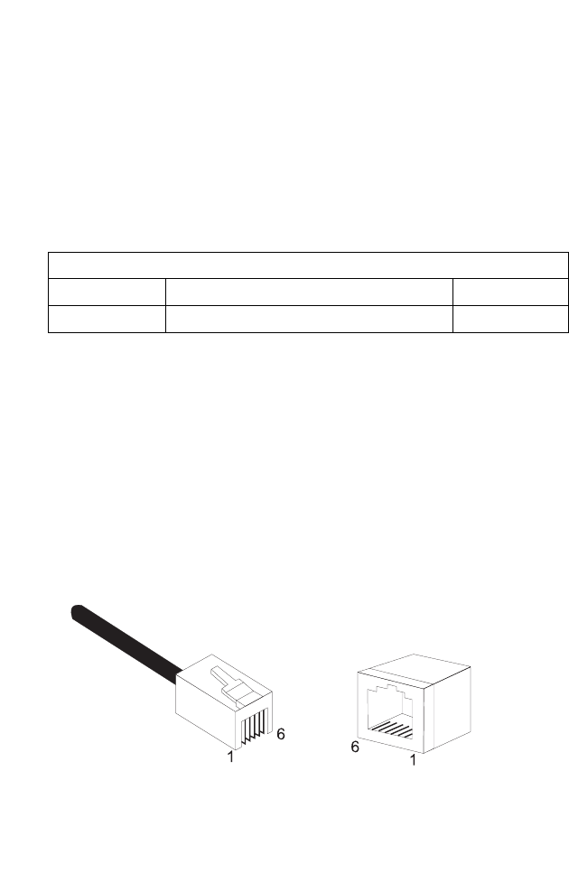
Each wire pair must be attached to the RJ-11 connectors in a specific
orientation. The following figure illustrates how the pins on the RJ-11
connector are numbered. Be sure to hold the connectors in the same
orientation when attaching the wires to the pins.
Figure B-2. RJ-11 Connector Pin Numbers
Cable Types and Specifications
Cable Type Connector
ADSL Line Standard Telephone Cable RJ-11
C
ABLES
B-6
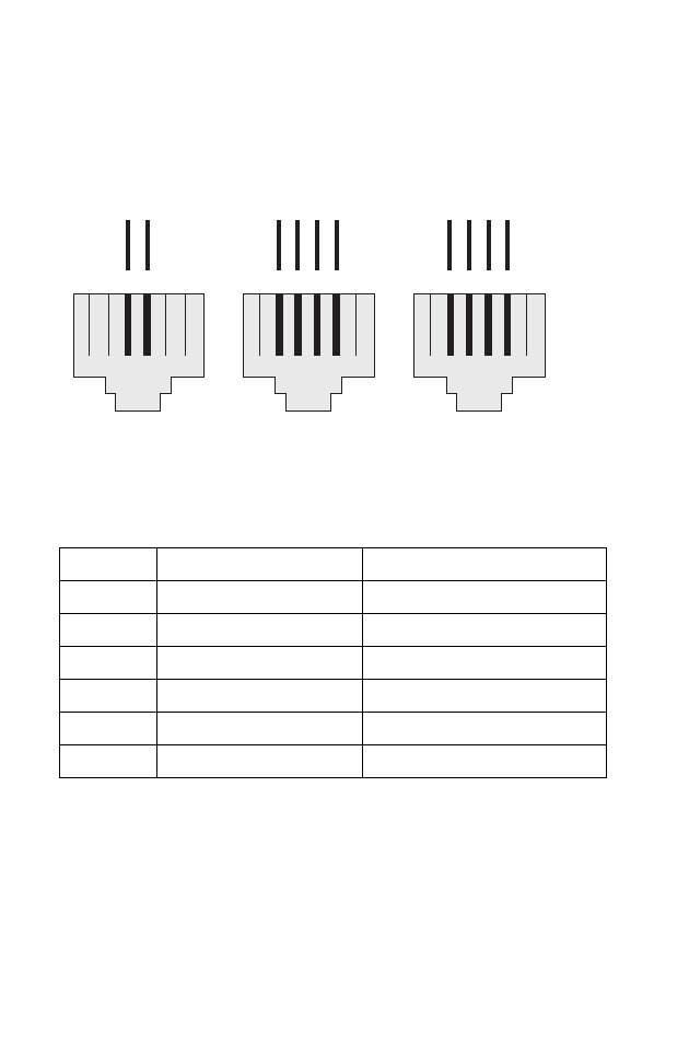
Figure B-3. RJ-11 Pinouts
Pin Signal Name Wire Color
1Not used
2 Line 2 Tip Black or White/Orange
3 Line 1 Ring Red or Blue/White
4 Line 1 Tip Green or White/Blue
5 Line 2 Ring Yellow or Orange/White
6Not used
123456
Blue/White
White/Blue
R1 T1
123456
Red
Green
R1 T1 R2T2
Black
Yellow
123456
Blue/White
White/Blue
R1 T1 R2T2
White/Orange
Orange/White
6x2 Jack 6x4 Jack6x4 Jack
T = Tip R = Ring

C-1
A
PPENDIX
C
S
PECIFICATIONS
Standards Compliance
CE Mark
Emissions
FCC Class B, VCCI Class B
Industry Canada Class B
EN55022 (CISPR 22) Class B
C-Tick - AS/NZS 3548 (1995) Class B
Immunity
EN 61000-3-2/3
EN 61000-4-2/3/4/5/6/8/11
Safety
UL 1950
EN60950 (TÜV)
CSA 22.2 No. 950
IEEE 802.3 10 BASE-T Ethernet
IEEE 802.3u 100 BASE-TX Fast Ethernet
IEEE 802.11b Wireless LAN
Modem Standards
ITU G.992.1 (G.dmt)
ITU G.992.2 (G.Lite)
ITU G.994.1 (G.handshake)
ITU T.413 issue 2 - ADSL full rate
LAN Interfaces
4 RJ-45 10 BASE-T/100 BASE-TX ports
Auto-negotiates the connection speed to 10 Mbps Ethernet or 100 Mbps
Fast Ethernet, and the transmission mode to half duplex or full duplex.
On-board wireless LAN card allows up to 253 wireless users to access
resources on the wired LAN.

S
PECIFICATIONS
C-2
WAN Interface
1 ADSL RJ-11 port
Indicator Panel
Power, Ethernet, ADSL Syn, ADSL Data
Dimensions
220 x 132.8 x 30.5 mm (8.66 x 5.23 x 1.20 in)
Weight
0.6 kg (1.32 lbs)
Input Power
12 V 1 A
Power Consumption
12 Watts max.
Management
Web management
Advanced Features
Dynamic IP Address Configuration – DHCP, DNS
Firewall – Client privileges, hacker prevention and logging, Stateful Packet
Inspection
Virtual Private Network – PPTP, IPSec pass-through, VPN pass-through
Internet Standards
RFC 826 ARP, RFC 791 IP, RFC 792 ICMP, RFC 768 UDP, RFC 793 TCP,
RFC 783 TFTP, RFC 1483 AAL5 Encapsulation, RFC 1661 PPP,
RFC 1866 HTML, RFC 2068 HTTP, RFC 2364 PPP over ATM
Temperature
Operating 0 to 40°C (32 to 104°F)
Storage -40 to 70°C (-40 to 158°F)
Humidity
5% to 95% (noncondensing)
Warranty
Limited Lifetime

Glossary-1
G
LOSSARY
10BASE-T
IEEE 802.3 specification for 10 Mbps Ethernet over two pairs of
Category 3, 4, or 5 UTP cable.
100BASE-TX
IEEE 802.3u specification for 100 Mbps Fast Ethernet over two pairs of
Category 5 UTP cable.
Access Point (AP)
An interface between the wireless network and a wired network. Access
points combined with a distribution system (e.g. Ethernet) support the
creation of multiple radio cells (BSSs) that enable roaming throughout a
facility.
Asymmetric Digital Subscriber Line (ADSL)
One of four DSL technologies. ADSL is designed to deliver more
bandwidth downstream (from the central office to the customer site) than
upstream. Downstream rates range from 1.5 to 9 Mbps, whereas upstream
bandwidth ranges from 16 to 640 kbps. ADSL transmissions work at
distances up to 18,000 feet (5,488 meters) over a single copper twisted pair.
Asynchronous Transfer Mode (ATM)
A cell-based connection-oriented data service offering high speed (up to
2.488 Gbps) data transfer. ATM integrates circuit and packet switching to
handle both constant and burst information. Frequently called cell relay.
Authentication
The process a station uses to announce its identify to another station.
IEEE 802.11 specifies two forms of authentication: open system and
shared key.

G
LOSSARY
Glossary-2
Bandwidth
The difference between the highest and lowest frequencies available for
network signals. Also synonymous with wire speed, the actual speed of the
data transmission along the cable.
Basic Service Set (BSS)
A set of 802.11-compliant stations that operate as a fully-connected
wireless network.
Cyclic Redundancy Check (CRC)
An error detection process that (at the transmitting station) divides the
data being sent by a particular polynomial and appends the resulting
remainder to the transmitted data. Then (at the receiving station) the
process divides the received data by the same polynomial and compares
the resulting remainder to the remainder appended to the data at the
transmitting station. If the remainders are equal, there is very high
probability that no errors are present in the data. If they do not match,
then errors are present.
Domain Naming System (DNS)
System used in the Internet for translating names of network nodes into
addresses.
Dynamic Host Configuration Protocol (DHCP)
Issues IP addresses automatically within a specified range to devices such
as PCs when they are first powered on. The device retains the use of the IP
address for a specific license period that the system administrator can
define. DHCP is available as part of the many operating systems including
Microsoft Windows NT Server and UNIX.

G
LOSSARY
Glossary-3
Ethernet
A network communication system developed and standardized by DEC,
Intel, and Xerox, using baseband transmission, CSMA/CD access, logical
bus topology, and coaxial cable. The successor IEEE 802.3 standard
provides for integration into the OSI model and extends the physical layer
and media with repeaters and implementations that operate on fiber, thin
coax and twisted-pair cable.
File Transfer Protocol (FTP)
A TCP/IP protocol for file transfer.
Firewall
A device that interfaces the network to the outside world and shields the
network from unauthorized users. The firewall does this by blocking
certain types of traffic. For example, some firewalls permit only electronic
mail traffic to enter the network from elsewhere. This helps protect the
network against attacks made to other network resources, such as sensitive
files, databases, and applications.
Forward Error Correction (FEC)
A method of error control where the receiving node automatically corrects
as many channel errors as it can without referring to the sending node.
G.lite
A standard that defines the more economical splitterless ADSL connection
that transmits data at up to 1.5 Mbps downstream and 512 Kbps upstream.
This ADSL option can be installed without an on-site visit by the service
provider.
IEEE
Institute of Electrical and Electronic Engineers.

G
LOSSARY
Glossary-4
IEEE 802.11
Specifies medium access and physical layer specifications for 1 Mbps and 2
Mbps wireless connectivity within a local area.
IEEE 802.3x
Defines Ethernet frame start/stop requests and timers used for flow
control on full-duplex links.
International Control Message Protocol (ICMP)
Network layer Internet protocol that reports errors and provides other
information relevant to IP packet processing. Documented in RFC 792.
Local Area Network (LAN)
A group of interconnected computer and support devices.
LED
Light emitting diode used for monitoring a device or network condition.
Logical Link Control Layer (LLC)
The highest layer of the IEEE 802 Reference Model and provides similar
functions of a traditional data link control protocol.
Management Information Base (MIB)
Database of network management information that is used and maintained
by a network management protocol such as SNMP or ICMP. The value of
a MIB object can be changed or retrieved using SNMP or ICMP
commands. MIB objects are organized in a tree structure that includes
public (standard) and private (proprietary) branches.
Media Access Control (MAC)
A portion of the networking protocol that governs access to the
transmission medium, facilitating the exchange of data between network
nodes.

G
LOSSARY
Glossary-5
Node
Any network-addressable device on the network, such as a router or
network interface card.
Point-to-Point Protocol (PPP)
A protocol that provides router-to-router and host-to-network
connections over both synchronous and asynchronous circuits. PPP is the
successor to SLIP.
RJ-45 Connector
A connector for twisted-pair wiring.
Routing Information Protocol (RIP)
A common type of routing protocol. RIP bases its routing path on the
distance (number of hops) to the destination. RIP maintains optimum
routing paths by sending out routing update messages if the network
topology changes. For example, if a router finds that a particular link is
faulty, it will update its routing table, then send a copy of the modified
table to each of its neighbors.
Service Set Identifier (SSID)
An identifier attached to packets sent over the wireless LAN that functions
as a “password” for joining a particular radio network (BSS). All radios and
access points within the same BSS must use the same SSID, or their
packets will be ignored.
Simple Network Monitoring Protocol (SNMP)
Defines the transfer of information between Management Information
Bases (MIBs). Most high-end network monitoring stations require the
implementation of SNMP on each of the components the organization
wishes to monitor.

G
LOSSARY
Glossary-6
Transmission Control Protocol (TCP)
A commonly used protocol for establishing and maintaining
communications between applications on different computers. TCP
provides full-duplex, acknowledged, and flow-controlled service to
upper-layer protocols and applications.
User Data Protocol (UDP)
A connectionless protocol that works at the OSI transport layer. UDP
transports datagrams but does not acknowledge their receipt.
UTP
Unshielded twisted-pair cable.
Virtual channel Identifier (VCI)
A 16-bit field in the header of an ATM cell. The VCI, together with VPI,
is used to identify the next destination of a cell as it passes through a series
of ATM switches on its way to its destination.
Virtual LAN (VLAN)
A collection of network nodes that share the same collision domain
regardless of their physical location or connection point in the network. A
VLAN serves as a logical workgroup with no physical barriers, allowing
users to share information and resources located on the same LAN.
Virtual Path Identifier (VPI)
A 8-bit field in the header of an ATM cell.
Wired Equivalent Privacy (WEP)
An optional IEEE 802.11 function that offers frame transmission privacy
similar to a wired network. The Wired Equivalent Privacy generates secret
shared encryption keys that both source and destination stations can use to
alter frame bits to avoid disclosure to eavesdroppers.

38 Tesla
Irvine, CA 92618
Phone: (949) 679-8000
FOR TECHNICAL SUPPORT, CALL:
From U.S.A. and Canada (24 hours a day, 7 days a week)
(800) SMC-4-YOU; (949) 679-8000; Fax: (949) 679-1481
From Europe (8:00 AM - 5:30 PM UK Time)
44 (0) 118 974 8700; Fax: 44 (0) 118 974 8701
INTERNET
E-mail addresses:
techsupport@smc.com
european.techsupport@smc-europe.com
support@smc-asia.com
Driver updates:
http://www.smc.com/index.cfm?action=tech_support_drivers_downloads
World Wide Web:
http://www.smc.com
http://www.smc-europe.com
http://www.smc-asia.com
FOR LITERATURE OR ADVERTISING RESPONSE, CALL:
U.S.A. and Canada: (800) SMC-4-YOU; Fax (949) 679-1481
Spain: 34-93-477-4935; Fax 34-93-477-3774
UK: 44 (0) 118 974 8700; Fax 44 (0) 118 974 8701
France: 33 (0) 41 38 32 32; Fax 33 (0) 41 38 01 58
Italy: 39 02 739 12 33; Fax 39 02 739 14 17
Benelux: 31 33 455 72 88; Fax 31 33 455 73 30
Central Europe: 49 (0) 89 92861-0; Fax 49 (0) 89 92861-230
Switzerland: 41 (0) 1 9409971; Fax 41 (0) 1 9409972
Nordic: 46 (0) 868 70700; Fax 46 (0) 887 62 62
Northern Europe: 44 (0) 118 974 8700; Fax 44 (0) 118 974 8701
Eastern Europe: 34 -93-477-4920; Fax 34 93 477 3774
Sub Saharian Africa: 27-11 314 1133; Fax 27-11 314 9133
North Africa: 34 93 477 4920; Fax 34 93 477 3774
Russia: 7 (095) 290 29 96; Fax 7 (095) 290 29 96
PRC (Beijing): 86-10-8251-1550; Fax 86-10-8251-1551
PRC (Shanghai): 86-21-6485-9922; Fax 86-21-6495-7924
Taiwan: 886-2-8797-8006; Fax 886-2-8797-6288
Asia Pacific: (65) 6 238 6556; Fax (65) 6 238 6466
Korea: 82-2-553-0860; Fax 82-2-553-7202
Japan: 81-3-5645-5715; Fax 81-3-5645-5716
Australia: 61-2-8875-7887; Fax 61-2-8875-7777
India: 91 22 5696 2790; Fax 91 22 5696 2794
Middle East: 97 14 299 4466 Fax 97 14 299 4664
Thailand: 66 2 651 8733 Fax 66 2 651 8737
If you are looking for further contact information, please visit www.smc.com,
www.smc-europe.com, or www.smc-asia.com.
Model Number: SMC7404WBRA
Pub. No: 150000018500E E032003-R01