Accton Technology ACC2632WV2 PCMCIA Radio Card with Molded Antenna User Manual smc2632w b
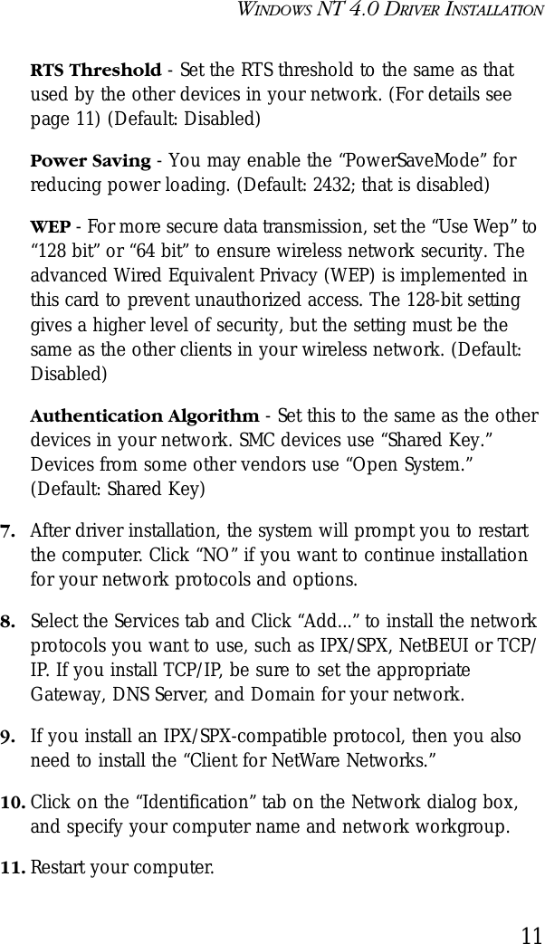
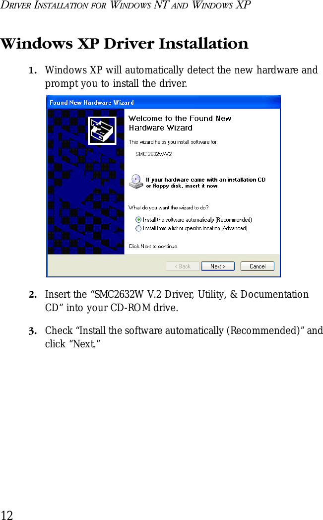
Accton Technology Corp PCMCIA Radio Card with Molded Antenna smc2632w b
UserManual.wiki
>
Accton Technology
>
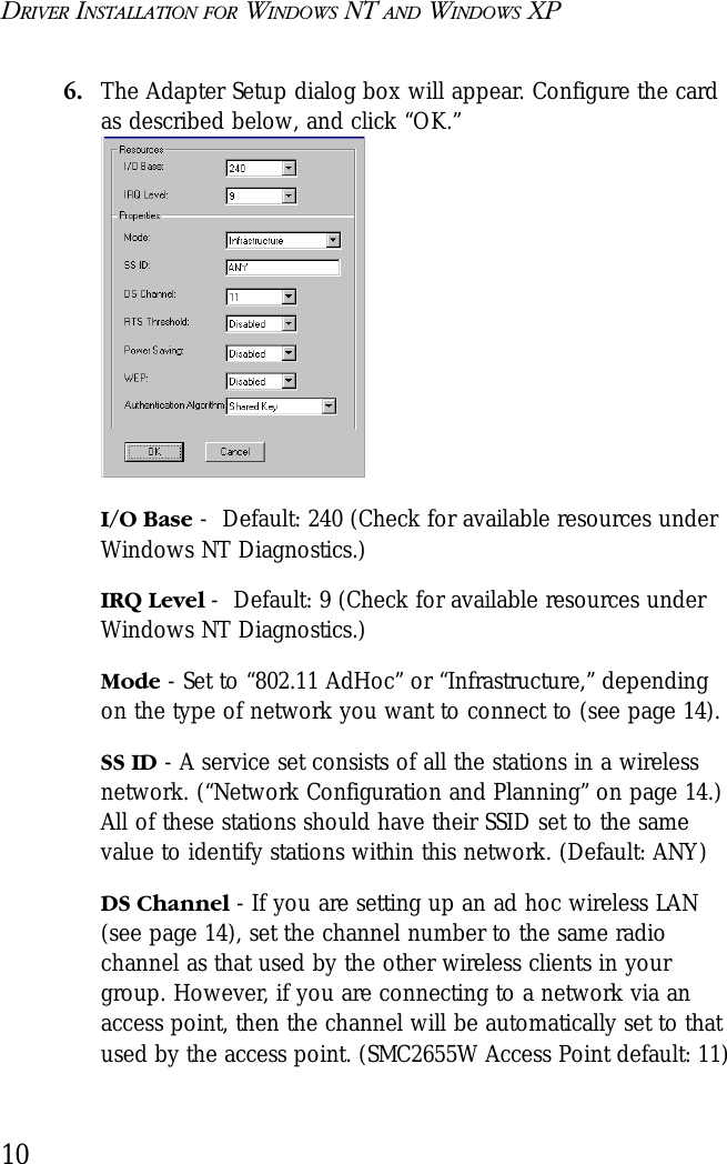
ACC2632WV2 User Manual
>
Users Manual Revised 043002
Contents
1.
DoC Statement
2.
Users Manual Revised 043002
Users Manual Revised 043002
Navigation menu
Upload a User Manual
Namespaces
Wiki Guide
HTML
PDF
Info
Views
User Manual
Discussion / Help
Navigation

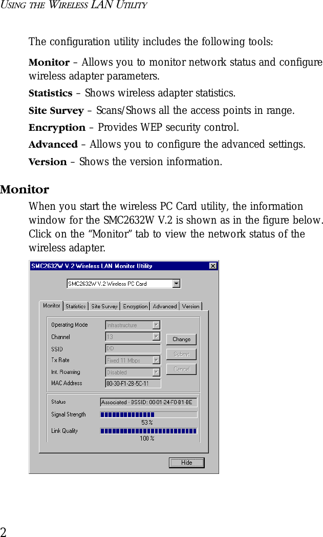
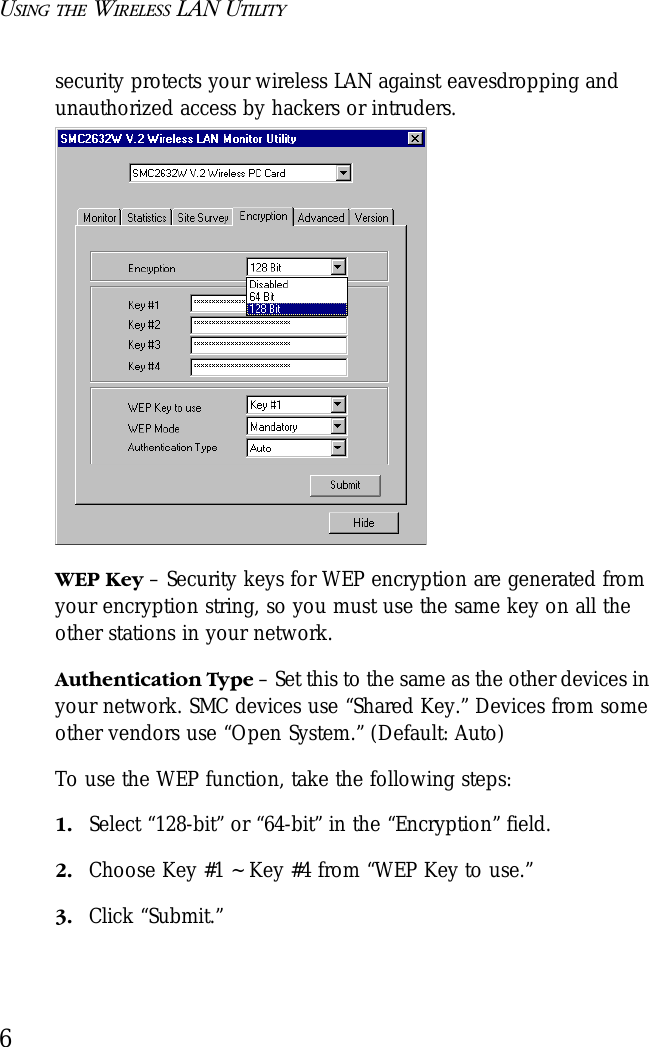
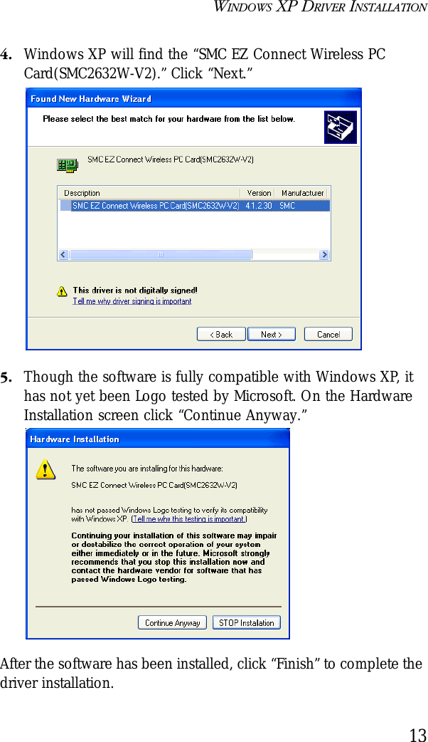
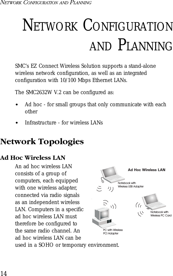
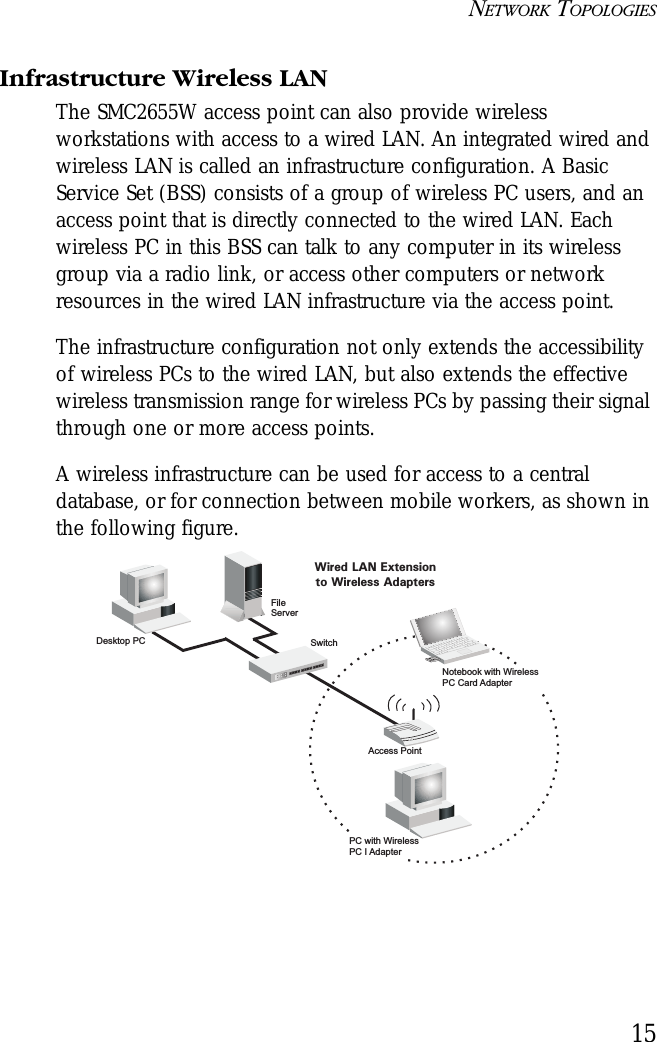
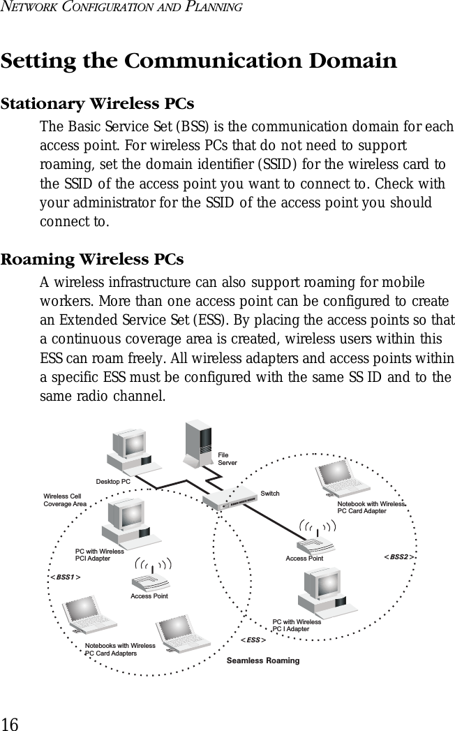
![9DRIVER INSTALLATION FORWINDOWS NT AND WINDOWS XPWindows NT 4.0 Driver Installation 1. Insert the PC Card into a standard Type II or III PCMCIA slot in your notebook.2. From the desktop, select “Control Panel,” double-click “Network,” click “Adapters,” and then click the “Add” button in the Network dialog box.3. Windows NT will present a list of all its supported adapters. Click “Have Disk” to continue. 4. Windows NT will ask for the drive/path containing the SMC2632W Windows NT drivers. Insert the provided CD into the CD-ROM drive, type “[CD-ROM drive]:\winNT4\,” and then click “OK.”5. Windows NT will attempt to locate the SYS and INF files in the specified path. If you have entered the path name correctly, Windows NT should copy the appropriate drivers to the Windows NT system. You need to acknowledge the selection by clicking “OK.”SMC EZ Connect Wireless PC Card(SMC2632W V-2)](https://usermanual.wiki/Accton-Technology/ACC2632WV2.Users-Manual-Revised-043002/User-Guide-240383-Page-21.png)