Accton Technology ACC2632WV2 PCMCIA Radio Card with Molded Antenna User Manual smc2632w b
Accton Technology Corp PCMCIA Radio Card with Molded Antenna smc2632w b
Contents
- 1. DoC Statement
- 2. Users Manual Revised 043002
Users Manual Revised 043002

EZ Connect
™
Wireless PC Card
11 Mbps data rate – provides alternative to wired LANs
that can dramatically cut costs
Working range up to 160 m (528 ft) at 11 Mbps,
350 m (1155 ft) at 1 Mbps
Seamless connectivity to wired Ethernet LANs
augments existing networks quickly and easily
DSSS technology provides robust,
interference-resistant, and secure wireless connections
Supports a wide range of operating systems
(Windows 95/98/Me/NT/2000/XP)
Easy installation
Built-in dual diversity antenna
User Guide
SMC2632W V.2

38 Tesla
Irvine, CA 92618
Phone: (949) 679-8000
EZ Connect Wireless PC Card
User Guide
The easy way to make all your network connections
April 2002
Revision Number: F1.0
E042002-R01

Copyright
Information furnished by SMC Networks, Inc. (SMC) is believed to be accurate and reliable.
However, no responsibility is assumed by SMC for its use, nor for any infringements of patents
or other rights of third parties which may result from its use. No license is granted by
implication or otherwise under any patent or patent rights of SMC. SMC reserves the right to
change specifications at any time without notice.
Copyright © 2002 by
SMC Networks, Inc.
38 Tesla
Irvine, CA 92618
All rights reserved. Printed in Taiwan
Trademarks:
SMC is a registered trademark; and EZ Connect is a trademark of SMC Networks, Inc. Other product and
company names are trademarks or registered trademarks of their respective holders.

i
L
IMITED
W
ARRANTY
Limited Warranty Statement: SMC Networks, Inc. (“SMC”) warrants its products
to be free from defects in workmanship and materials, under normal use and
service, for the applicable warranty term. All SMC products carry a standard 90-day
limited warranty from the date of purchase from SMC or its Authorized Reseller.
SMC may, at its own discretion, repair or replace any product not operating as
warranted with a similar or functionally equivalent product, during the applicable
warranty term. SMC will endeavor to repair or replace any product returned under
warranty within 30 days of receipt of the product.
The standard limited warranty can be upgraded to a Limited Lifetime* warranty by
registering new products within 30 days of purchase from SMC or its Authorized
Reseller. Registration can be accomplished via the enclosed product registration
card or online via the SMC web site. Failure to register will not affect the standard
limited warranty. The Limited Lifetime warranty covers a product during the Life of
that Product, which is defined as the period of time during which the product is an
“Active” SMC product. A product is considered to be “Active” while it is listed on
the current SMC price list. As new technologies emerge, older technologies become
obsolete and SMC will, at its discretion, replace an older product in its product line
with one that incorporates these newer technologies. At that point, the obsolete
product is discontinued and is no longer an “Active” SMC product. A list of
discontinued products with their respective dates of discontinuance can be found
at: http://www.smc.com/index.cfm?action=customer_service_warranty.
All products that are replaced become the property of SMC. Replacement products
may be either new or reconditioned. Any replaced or repaired product carries
either a 30-day limited warranty or the remainder of the initial warranty, whichever
is longer. SMC is not responsible for any custom software or firmware,
configuration information, or memory data of Customer contained in, stored on, or
integrated with any products returned to SMC pursuant to any warranty. Products
returned to SMC should have any customer-installed accessory or add-on
components, such as expansion modules, removed prior to returning the product
for replacement. SMC is not responsible for these items if they are returned with the
product.
Customers must contact SMC for a Return Material Authorization number prior to
returning any product to SMC. Proof of purchase may be required. Any product
returned to SMC without a valid Return Material Authorization (RMA) number
clearly marked on the outside of the package will be returned to customer at
customer’s expense. For warranty claims within North America, please call our
toll-free customer support number at (800) 762-4968. Customers are responsible for
all shipping charges from their facility to SMC. SMC is responsible for return
shipping charges from SMC to customer.

L
IMITED
W
ARRANTY
ii
WARRANTIES EXCLUSIVE: IF AN SMC PRODUCT DOES NOT OPERATE AS
WARRANTED ABOVE, CUSTOMER’S SOLE REMEDY SHALL BE REPAIR OR
REPLACEMENT OF THE PRODUCT IN QUESTION, AT SMC’S OPTION. THE
FOREGOING WARRANTIES AND REMEDIES ARE EXCLUSIVE AND ARE IN LIEU
OF ALL OTHER WARRANTIES OR CONDITIONS, EXPRESS OR IMPLIED, EITHER
IN FACT OR BY OPERATION OF LAW, STATUTORY OR OTHERWISE, INCLUDING
WARRANTIES OR CONDITIONS OF MERCHANTABILITY AND FITNESS FOR A
PARTICULAR PURPOSE. SMC NEITHER ASSUMES NOR AUTHORIZES ANY OTHER
PERSON TO ASSUME FOR IT ANY OTHER LIABILITY IN CONNECTION WITH
THE SALE, INSTALLATION, MAINTENANCE OR USE OF ITS PRODUCTS. SMC
SHALL NOT BE LIABLE UNDER THIS WARRANTY IF ITS TESTING AND
EXAMINATION DISCLOSE THE ALLEGED DEFECT IN THE PRODUCT DOES NOT
EXIST OR WAS CAUSED BY CUSTOMER’S OR ANY THIRD PERSON’S MISUSE,
NEGLECT, IMPROPER INSTALLATION OR TESTING, UNAUTHORIZED ATTEMPTS
TO REPAIR, OR ANY OTHER CAUSE BEYOND THE RANGE OF THE INTENDED
USE, OR BY ACCIDENT, FIRE, LIGHTNING, OR OTHER HAZARD.
LIMITATION OF LIABILITY: IN NO EVENT, WHETHER BASED IN CONTRACT OR
TORT (INCLUDING NEGLIGENCE), SHALL SMC BE LIABLE FOR INCIDENTAL,
CONSEQUENTIAL, INDIRECT, SPECIAL, OR PUNITIVE DAMAGES OF ANY KIND,
OR FOR LOSS OF REVENUE, LOSS OF BUSINESS, OR OTHER FINANCIAL LOSS
ARISING OUT OF OR IN CONNECTION WITH THE SALE, INSTALLATION,
MAINTENANCE, USE, PERFORMANCE, FAILURE, OR INTERRUPTION OF ITS
PRODUCTS, EVEN IF SMC OR ITS AUTHORIZED RESELLER HAS BEEN ADVISED
OF THE POSSIBILITY OF SUCH DAMAGES.
SOME STATES DO NOT ALLOW THE EXCLUSION OF IMPLIED WARRANTIES OR
THE LIMITATION OF INCIDENTAL OR CONSEQUENTIAL DAMAGES FOR
CONSUMER PRODUCTS, SO THE ABOVE LIMITATIONS AND EXCLUSIONS MAY
NOT APPLY TO YOU. THIS WARRANTY GIVES YOU SPECIFIC LEGAL RIGHTS,
WHICH MAY VARY FROM STATE TO STATE. NOTHING IN THIS WARRANTY
SHALL BE TAKEN TO AFFECT YOUR STATUTORY RIGHTS.
* SMC will provide warranty service for one year following discontinuance from the
active SMC price list. Under the limited lifetime warranty, internal and external
power supplies, fans, and cables are covered by a standard one-year warranty from
date of purchase.
SMC Networks, Inc.
38 Tesla
Irvine, CA 92618

iii
COMPLIANCES
FCC - Class B
This equipment has been tested and found to comply with the limits for a Class B
digital device, pursuant to Part 15 of the FCC Rules. These limits are designed to
provide reasonable protection against harmful interference in a residential
installation. This equipment generates, uses and can radiate radio frequency energy
and, if not installed and used in accordance with instructions, may cause harmful
interference to radio communications. However, there is no guarantee that the
interference will not occur in a particular installation. If this equipment does cause
harmful interference to radio or television reception, which can be determined by
turning the equipment off and on, the user is encouraged to try to correct the
interference by one or more of the following measures:
•Reorient the receiving antenna
•Increase the separation between the equipment and receiver
•Connect the equipment into an outlet on a circuit different from that to which
the receiver is connected
•Consult the dealer or an experienced radio/TV technician for help
FCC Caution: To assure continued compliance, (example - use only shielded
interface cables when connecting to computer or peripheral devices). Any changes
or modifications not expressly approved by the party responsible for compliance
could void the user’s authority to operate this equipment.
This device complies with Part 15 of the FCC Rules. Operation is subject to the
following two conditions: (1) This device may not cause harmful interference, and
(2) this device must accept any interference received, including interference that
may cause undesired operation.
CAUTION STATEMENT:
FCC Radiation Exposure Statement
This equipment complies with FCC radiation exposure limits set forth for an
uncontrolled environment. This equipment should be installed and operated with a
minimum distance of 2.5 centimeters between the radiator and your body. This
transmitter must not be co-located or operating in conjunction with any other
antenna or transmitter.
Note:
In order to maintain compliance with the limits of a Class B digital device,
SMC requires that you use a quality interface cable when connecting to this
device. Changes or modifications not expressly approved by SMC could
void the user’s authority to operate this equipment.
Attach unshielded twisted-pair cable (UTP) to the RJ-45 port and shielded
USB cable to the USB port.

C
OMPLIANCES
iv
Industry Canada - Class B
This digital apparatus does not exceed the Class B limits for radio noise emissions
from digital apparatus as set out in the interference-causing equipment standard
entitled “Digital Apparatus,” ICES-003 of Industry Canada.
Cet appareil numérique respecte les limites de bruits radioélectriques applicables
aux appareils numériques de Classe B prescrites dans la norme sur le matérial
brouilleur: “Appareils Numériques,” NMB-003 édictée par l’Industrie.
EC Conformance Declaration - Class B
SMC contact for these products in Europe is:
SMC Networks Europe,
Edificio Conata II,
Calle Fructuós Gelabert 6-8, 2o, 4a,
08970 - Sant Joan Despí,
Barcelona, Spain.
This information technology equipment complies with the requirements of the
Council Directive 89/336/EEC on the Approximation of the laws of the Member
States relating to Electromagnetic Compatibility and 73/23/EEC for electrical
equipment used within certain voltage limits and the Amendment Directive 93/68/
EEC. For the evaluation of the compliance with these Directives, the following
standards were applied:
RFI Emission:
•Limit class B according to EN 55022:1998
•Limit class B for harmonic current emission according to
EN 61000-3-2/1995
•Limitation of voltage fluctuation and flicker in low-voltage
supply system according to EN 61000-3-3/1995
Immunity:
•Product family standard according to EN 55024:1998
•Electrostatic Discharge according to EN 61000-4-2:1995
(Contact Discharge: ±4 kV, Air Discharge: ±8 kV)
•Radio-frequency electromagnetic field according to
EN 61000-4-3:1996 (80 - 1000 MHz with 1 kHz AM 80%
Modulation: 3 V/m)
•Electrical fast transient/burst according to EN 61000-4-4:1995
(AC/DC power supply: ±1 kV, Data/Signal lines: ±0.5 kV)
•Surge immunity test according to EN 61000-4-5:1995
(AC/DC Line to Line: ±1 kV, AC/DC Line to Earth: ±2 kV)
•Immunity to conducted disturbances, Induced by
radio-frequency fields: EN 61000-4-6:1996 (0.15 - 80 MHz with
1 kHz AM 80% Modulation: 3 V/m)

C
OMPLIANCES
v
Safety Compliance
Wichtige Sicherheitshinweise (Germany)
1. Bitte lesen Sie diese Hinweise sorgfältig durch.
2. Heben Sie diese Anleitung für den späteren Gebrauch auf.
3. Vor jedem Reinigen ist das Gerät vom Stromnetz zu trennen. Verwenden Sie
keine Flüssigoder Aerosolreiniger. Am besten eignet sich ein angefeuchtetes
Tuch zur Reinigung.
4. Die Netzanschlu ßsteckdose soll nahe dem Gerät angebracht und leicht
zugänglich sein.
5. Das Gerät ist vor Feuchtigkeit zu schützen.
6. Bei der Aufstellung des Gerätes ist auf sicheren Stand zu achten. Ein Kippen
oder Fallen könnte Beschädigungen hervorrufen.
7. Die Belüftungsöffnungen dienen der Luftzirkulation, die das Gerät vor Überhit-
zung schützt. Sorgen Sie dafür, daß diese Öffnungen nicht abgedeckt werden.
8. Beachten Sie beim Anschluß an das Stromnetz die Anschlußwerte.
9. Verlegen Sie die Netzanschlußleitung so, daß niemand darüber fallen kann. Es
sollte auch nichts auf der Leitung abgestellt werden.
10.Alle Hinweise und Warnungen, die sich am Gerät befinden, sind zu beachten.
11.Wird das Gerät über einen längeren Zeitraum nicht benutzt, sollten Sie es vom
Stromnetz trennen. Somit wird im Falle einer Überspannung eine Beschädigung
vermieden.
12.Durch die Lüftungsöffnungen dürfen niemals Gegenstände oder Flüssigkeiten in
das Gerät gelangen. Dies könnte einen Brand bzw. elektrischen Schlag aus-
lösen.
13.Öffnen sie niemals das Gerät. Das Gerät darf aus Gründen der elektrischen
Sicherheit nur von authorisiertem Servicepersonal geöffnet werden.
•Power frequency magnetic field immunity test according to
EN 61000-4-8:1993 (1 A/m at frequency 50 Hz)
•Voltage dips, short interruptions and voltage variations immunity
test according to EN 61000-4-11:1994 (>95% Reduction @10 ms,
30% Reduction @500 ms, >95% Reduction @5000 ms)
LVD:
•EN 60950 (A1/1992; A2/1993; A3/1993; A4/1995; A11/1997)

C
OMPLIANCES
vi
14.Wenn folgende Situationen auftreten ist das Gerät vom Stromnetz zu trennen
und von einer qualifizierten Servicestelle zu überprüfen:
a.Netzkabel oder Netzstecker sind beschädigt.
b.Flüssigkeit ist in das Gerät eingedrungen.
c.Das Gerät war Feuchtigkeit ausgesetzt.
d.Wenn das Gerät nicht der Bedienungsanleitung entsprechend funktioniert oder
Sie mit Hilfe dieser Anleitung keine Verbesserung erzielen.
e.Das Gerät ist gefallen und/oder das Gehäuse ist beschädigt.
f. Wenn das Gerät deutliche Anzeichen eines Defektes aufweist.
15. Stellen Sie sicher, daß die Stromversorgung dieses Gerätes nach der EN 60950
geprüft ist. Ausgangswerte der Stromversorgung sollten die Werte von AC 7,5-8V,
50-60Hz nicht über oder unterschreiten sowie den minimalen Strom von 1A nicht
unterschreiten.
Der arbeitsplatzbezogene Schalldruckpegel nach DIN 45 635 Teil 1000 beträgt
70dB(A) oder weniger.

vii
T
ABLE
OF
C
ONTENTS
Using the Wireless LAN Utility . . . . . . . . . . . . . . . .1
Using the SMC2632W WLAN Utility . . . . . . . . . . . . . . . . . . . . . 1
Quick-Launch Icon . . . . . . . . . . . . . . . . . . . . . . . . . . . . . 1
Monitor . . . . . . . . . . . . . . . . . . . . . . . . . . . . . . . . . . . . . 2
Statistics . . . . . . . . . . . . . . . . . . . . . . . . . . . . . . . . . . . . . 4
Site Survey . . . . . . . . . . . . . . . . . . . . . . . . . . . . . . . . . . . 5
Encryption . . . . . . . . . . . . . . . . . . . . . . . . . . . . . . . . . . . 5
Advanced Screen . . . . . . . . . . . . . . . . . . . . . . . . . . . . . . 7
Version . . . . . . . . . . . . . . . . . . . . . . . . . . . . . . . . . . . . . 8
Driver Installation for Windows NT and
Windows XP . . . . . . . . . . . . . . . . . . . . . . . . . . .9
Windows NT 4.0 Driver Installation . . . . . . . . . . . . . . . . . . . . . 9
Windows XP Driver Installation . . . . . . . . . . . . . . . . . . . . . . . 12
Network Configuration and Planning . . . . . . . . .14
Network Topologies . . . . . . . . . . . . . . . . . . . . . . . . . . . . . . . 14
Ad Hoc Wireless LAN . . . . . . . . . . . . . . . . . . . . . . . . . . 14
Infrastructure Wireless LAN . . . . . . . . . . . . . . . . . . . . . . 15
Setting the Communication Domain . . . . . . . . . . . . . . . . . . . . 16
Stationary Wireless PCs . . . . . . . . . . . . . . . . . . . . . . . . . 16
Roaming Wireless PCs . . . . . . . . . . . . . . . . . . . . . . . . . 16
Troubleshooting . . . . . . . . . . . . . . . . . . . . . . . . . .18
Adapter Installation Problems . . . . . . . . . . . . . . . . . . . . . . . . . 18
Network Connection Problems . . . . . . . . . . . . . . . . . . . . . . . . 19
SMC Networks 802.11b Wireless Product Maximum Distance
Table . . . . . . . . . . . . . . . . . . . . . . . . . . . . . . . . . 21
Specifications . . . . . . . . . . . . . . . . . . . . . . . . . . . . .22
General Specifications . . . . . . . . . . . . . . . . . . . . . . . . . . . . . . 22
Software Drivers . . . . . . . . . . . . . . . . . . . . . . . . . . . . . . . . . . 23
Terminology . . . . . . . . . . . . . . . . . . . . . . . . . . . . .24

T
ABLE
OF
C
ONTENTS
viii
1
U
SING
THE
W
IRELESS
LAN
U
TILITY
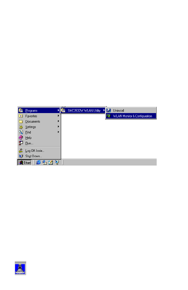
Using the SMC2632W WLAN Utility
Once the installation is complete, the configuration utility can be
accessed from the “Start” menu, as shown below.
Quick-Launch Icon
When the utility program is running, there will be a quick launch
icon in the lower right-hand corner of the task bar. If the icon is on
BLUE, you have a good connection. If it shows RED, you may
need to check the access point (such as SMC2655W Wireless
Access Point) and place it in a higher position, or move closer to
the access point you wish to connect to.
Double-clicking the quick launch icon will open the EZ Connect
Wireless PC Card Utility program, providing quick access to the
adapter settings.
U
SING
THE
W
IRELESS
LAN U
TILITY
2
The configuration utility includes the following tools:
Monitor – Allows you to monitor network status and configure
wireless adapter parameters.
Statistics – Shows wireless adapter statistics.
Site Survey – Scans/Shows all the access points in range.
Encryption – Provides WEP security control.
Advanced – Allows you to configure the advanced settings.
Version – Shows the version information.
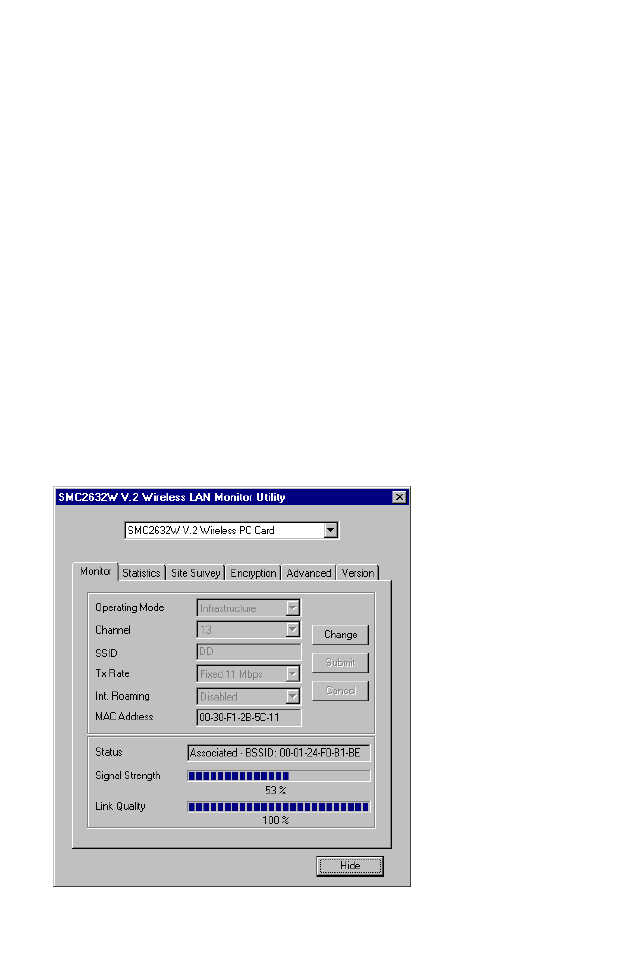
Monitor
When you start the wireless PC Card utility, the information
window for the SMC2632W V.2 is shown as in the figure below.
Click on the “Monitor” tab to view the network status of the
wireless adapter.

U
SING
THE
SMC2632W WLAN U
TILITY
3
Click “Change” to configure the “Operating Mode,” “Channel,”
“SSID” and “Tx Rate.” After making a configuration change, the
Submit button will become enabled. Click “Submit” to save the
changes.
Operating Mode – Set the station operation mode to “802.11 Ad
Hoc” for network configurations that do not have an access point,
or to “Infrastructure” for configurations with an access point
(“Infrastructure” is the default setting.)
Channel – If you are setting up an ad hoc wireless LAN (See
“Network Topologies” on page 14.), set the channel number to the
same radio channel as that used by the other wireless clients in
your group. However, if you are connecting to a network via an
access point, then the channel is automatically set to the channel
of the access point to which the adapter connects.
Note: The Channel can only be set when the Operating Mode is
“802.11 Ad-Hoc.”
SSID – Input an SSID string for the wireless network to which you
want to connect (“WLAN” is the default setting.) If you will be
roaming among multiple access points with different BSSIDs, set
the SSID to “ANY” to allow connection to any access point.
Tx Rate – Indicates the data transmission rate. Select an
appropriate transmission speed. Lower speeds will give better
range. (Default: Auto.)
Status - Shows the MAC address of the associated access point
(BSS ID).
Signal Strength – Shows the relative strength of the wireless
connection to the access point.
Link Quality – Shows the relative link quality (e.g., lack of frame
errors) of the wireless connection to the access point.
U
SING
THE
W
IRELESS
LAN U
TILITY
4
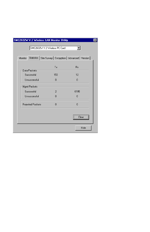
Statistics
The Statistics screen displays “Data Frames” and “Management
Frames.”
5
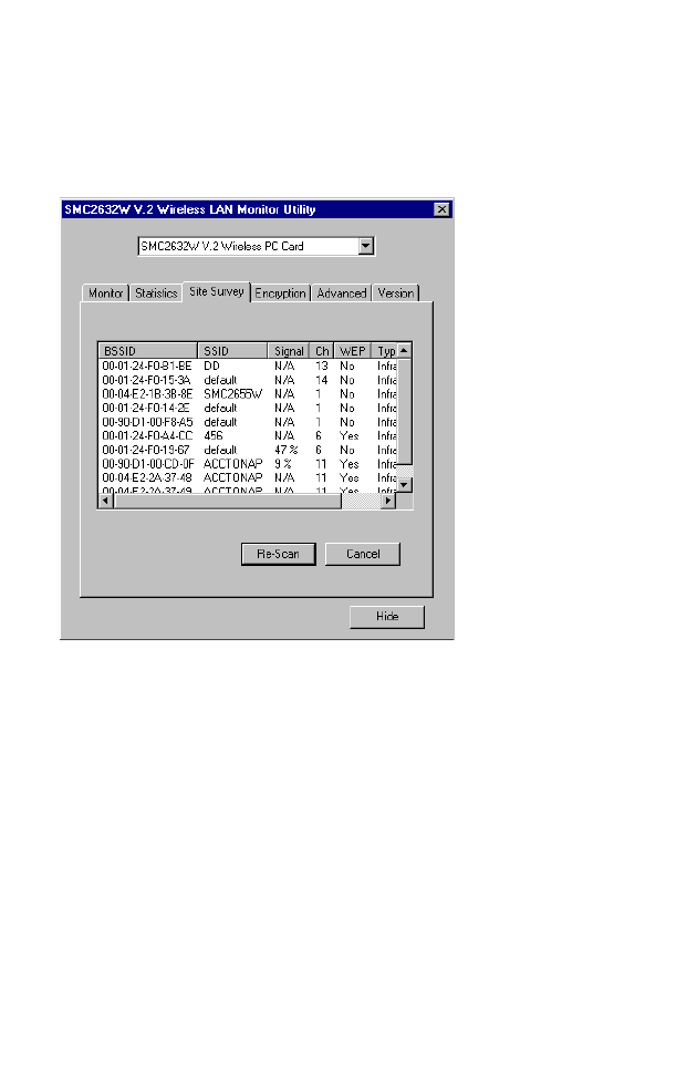
Site Survey
The Site Survey screen displays all access points in the wireless
LAN. You can choose one of them to connect to by
double-clicking on an entry.
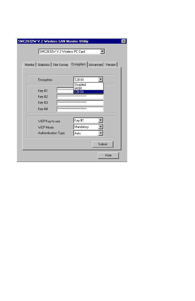
Encryption
Encryption – Wired Equivalent Privacy (WEP) is implemented in
the adapter to prevent unauthorized access. For more secure data
transmissions, set encryption to “128-bit” or “64-bit”. The 128-bit
setting gives a higher level of security. The setting must be the
same for all clients in your wireless network (Default: Disabled).
The WEP (Wired Equivalent Privacy) implemented in SMC’s EZ
Connect Wireless PC Card is based on the RC4 encryption
algorithm. The security keys are four 10 digit keys for the 64-bit
WEP setting and one 26-digit key for the 128-bit WEP setting. WEP
U
SING
THE
W
IRELESS
LAN U
TILITY
6
security protects your wireless LAN against eavesdropping and
unauthorized access by hackers or intruders.
WEP Key – Security keys for WEP encryption are generated from
your encryption string, so you must use the same key on all the
other stations in your network.
Authentication Type – Set this to the same as the other devices in
your network. SMC devices use “Shared Key.” Devices from some
other vendors use “Open System.” (Default: Auto)
To use the WEP function, take the following steps:
1. Select “128-bit” or “64-bit” in the “Encryption” field.
2. Choose Key #1 ~ Key #4 from “WEP Key to use.”
3. Click “Submit.”
U
SING
THE
SMC2632W WLAN U
TILITY
7
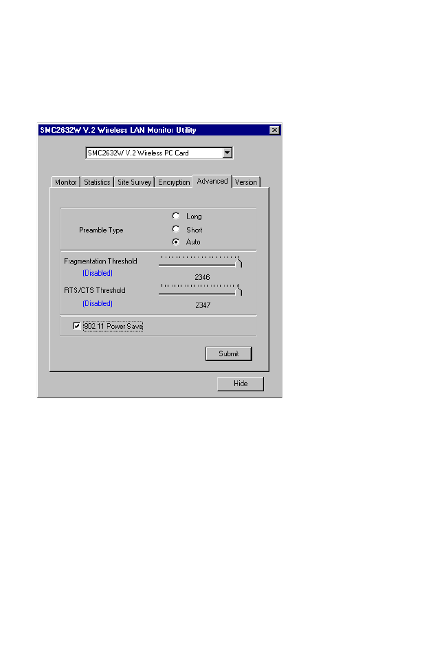
Advanced Screen
You can use this screen to set values for “Fragmentation
Threshold” (Default: 2346 means Disabled), and “RTS/CTS
Threshold” (Default: 2347 means Disabled).
U
SING
THE
W
IRELESS
LAN U
TILITY
8
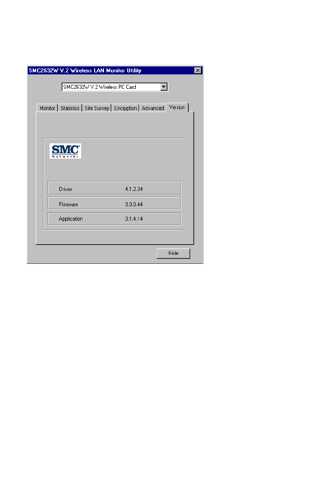
Version
The following screen shows the version information.

9
D
RIVER
I
NSTALLATION
FOR
W
INDOWS
NT
AND
W
INDOWS
XP
Windows NT 4.0 Driver Installation
1. Insert the PC Card into a standard Type II or III PCMCIA slot in
your notebook.
2. From the desktop, select “Control Panel,” double-click
“Network,” click “Adapters,” and then click the “Add” button in
the Network dialog box.
3. Windows NT will present a list of all its supported adapters.
Click “Have Disk” to continue.
4. Windows NT will ask for the drive/path containing the
SMC2632W Windows NT drivers. Insert the provided CD into
the CD-ROM drive, type “[CD-ROM drive]:\winNT4\,” and then
click “OK.”
5. Windows NT will attempt to locate the SYS and INF files in the
specified path. If you have entered the path name correctly,
Windows NT should copy the appropriate drivers to the
Windows NT system. You need to acknowledge the selection
by clicking “OK.”
SMC EZ Connect Wireless PC Card(SMC2632W V-2)
D
RIVER
I
NSTALLATION
FOR
W
INDOWS
NT
AND
W
INDOWS
XP
10
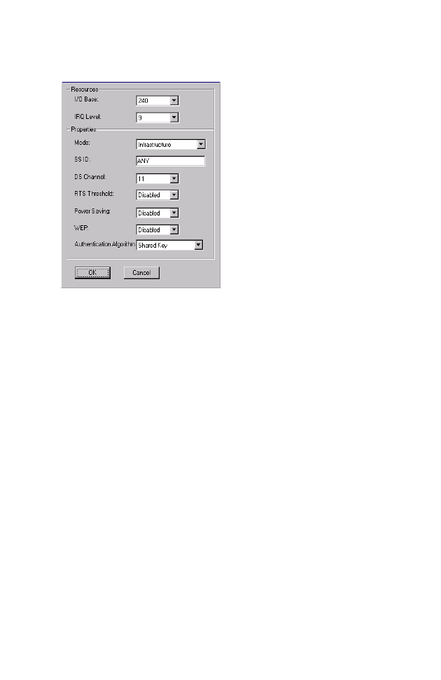
6. The Adapter Setup dialog box will appear. Configure the card
as described below, and click “OK.”
I/O Base - Default: 240 (Check for available resources under
Windows NT Diagnostics.)
IRQ Level - Default: 9 (Check for available resources under
Windows NT Diagnostics.)
Mode - Set to “802.11 AdHoc” or “Infrastructure,” depending
on the type of network you want to connect to (see page 14).
SS ID - A service set consists of all the stations in a wireless
network. (“Network Configuration and Planning” on page 14.)
All of these stations should have their SSID set to the same
value to identify stations within this network. (Default: ANY)
DS Channel - If you are setting up an ad hoc wireless LAN
(see page 14), set the channel number to the same radio
channel as that used by the other wireless clients in your
group. However, if you are connecting to a network via an
access point, then the channel will be automatically set to that
used by the access point. (SMC2655W Access Point default: 11)

W
INDOWS
NT 4.0 D
RIVER
I
NSTALLATION
11
RTS Threshold - Set the RTS threshold to the same as that
used by the other devices in your network. (For details see
page 11) (Default: Disabled)
Power Saving - You may enable the “PowerSaveMode” for
reducing power loading. (Default: 2432; that is disabled)
WEP - For more secure data transmission, set the “Use Wep” to
“128 bit” or “64 bit” to ensure wireless network security. The
advanced Wired Equivalent Privacy (WEP) is implemented in
this card to prevent unauthorized access. The 128-bit setting
gives a higher level of security, but the setting must be the
same as the other clients in your wireless network. (Default:
Disabled)
Authentication Algorithm - Set this to the same as the other
devices in your network. SMC devices use “Shared Key.”
Devices from some other vendors use “Open System.”
(Default: Shared Key)
7. After driver installation, the system will prompt you to restart
the computer. Click “NO” if you want to continue installation
for your network protocols and options.
8. Select the Services tab and Click “Add...” to install the network
protocols you want to use, such as IPX/SPX, NetBEUI or TCP/
IP. If you install TCP/IP, be sure to set the appropriate
Gateway, DNS Server, and Domain for your network.
9. If you install an IPX/SPX-compatible protocol, then you also
need to install the “Client for NetWare Networks.”
10. Click on the “Identification” tab on the Network dialog box,
and specify your computer name and network workgroup.
11. Restart your computer.
D
RIVER
I
NSTALLATION
FOR
W
INDOWS
NT
AND
W
INDOWS
XP
12
Windows XP Driver Installation
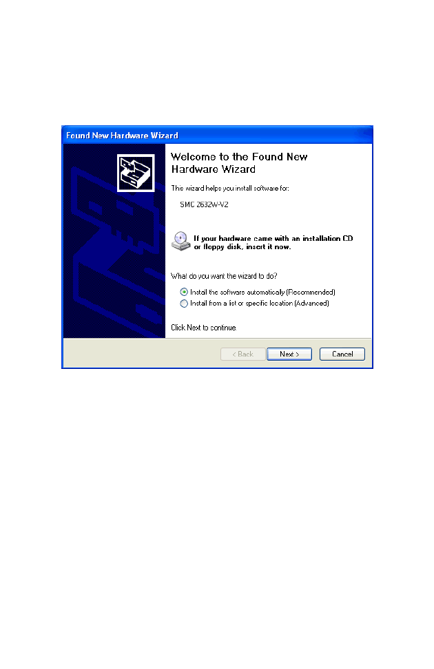
1. Windows XP will automatically detect the new hardware and
prompt you to install the driver.
2. Insert the “SMC2632W V.2 Driver, Utility, & Documentation
CD” into your CD-ROM drive.
3. Check “Install the software automatically (Recommended)” and
click “Next.”
W
INDOWS
XP D
RIVER
I
NSTALLATION
13
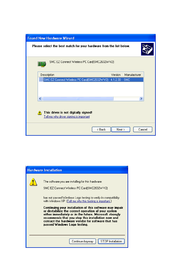
4. Windows XP will find the “SMC EZ Connect Wireless PC
Card(SMC2632W-V2).” Click “Next.”
5. Though the software is fully compatible with Windows XP, it
has not yet been Logo tested by Microsoft. On the Hardware
Installation screen click “Continue Anyway.”
After the software has been installed, click “Finish” to complete the
driver installation.
N
ETWORK
C
ONFIGURATION
AND
P
LANNING
14
N
ETWORK
C
ONFIGURATION
AND
P
LANNING
SMC’s EZ Connect Wireless Solution supports a stand-alone
wireless network configuration, as well as an integrated
configuration with 10/100 Mbps Ethernet LANs.
The SMC2632W V.2 can be configured as:
•Ad hoc - for small groups that only communicate with each
other
•Infrastructure - for wireless LANs
Network Topologies
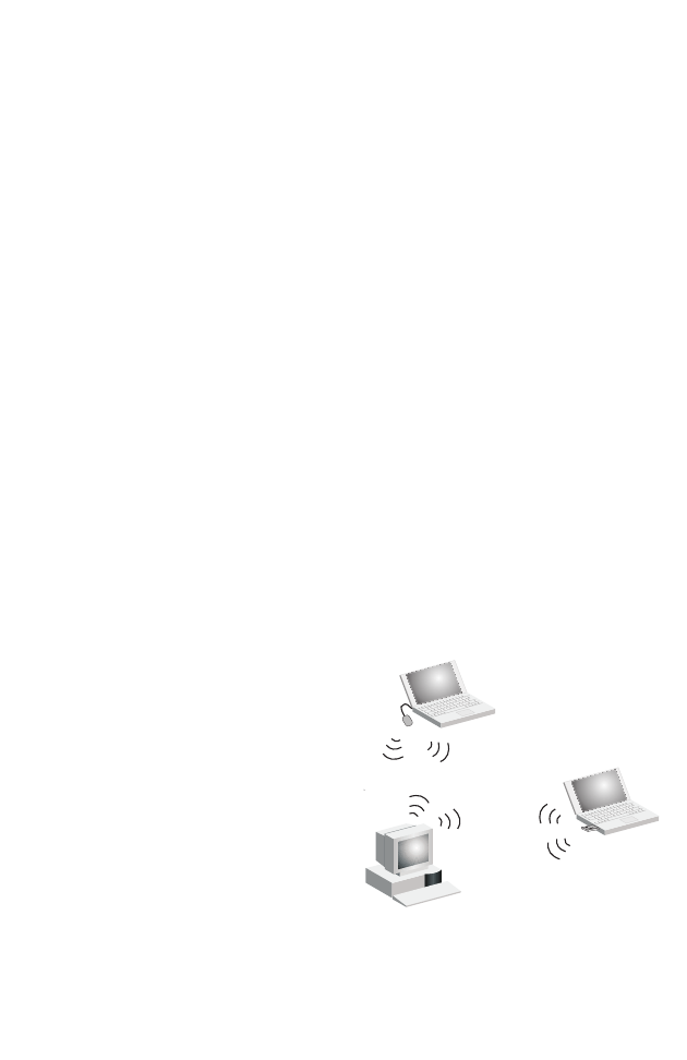
Ad Hoc Wireless LAN
An ad hoc wireless LAN
consists of a group of
computers, each equipped
with one wireless adapter,
connected via radio signals
as an independent wireless
LAN. Computers in a specific
ad hoc wireless LAN must
therefore be configured to
the same radio channel. An
ad hoc wireless LAN can be
used in a SOHO or temporary environment.
Ad Hoc Wireless LAN
Notebook with
Wireless USB Adapter
Notebook with
Wireless PC Card
PC with Wireless
PCI Adapter
N
ETWORK
T
OPOLOGIES
15
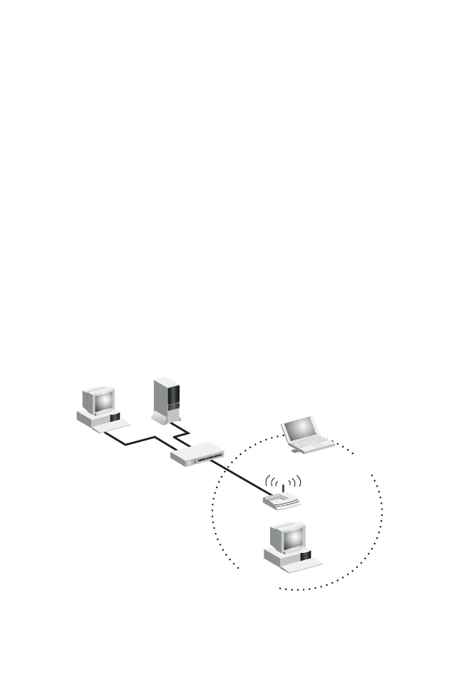
Infrastructure Wireless LAN
The SMC2655W access point can also provide wireless
workstations with access to a wired LAN. An integrated wired and
wireless LAN is called an infrastructure configuration. A Basic
Service Set (BSS) consists of a group of wireless PC users, and an
access point that is directly connected to the wired LAN. Each
wireless PC in this BSS can talk to any computer in its wireless
group via a radio link, or access other computers or network
resources in the wired LAN infrastructure via the access point.
The infrastructure configuration not only extends the accessibility
of wireless PCs to the wired LAN, but also extends the effective
wireless transmission range for wireless PCs by passing their signal
through one or more access points.
A wireless infrastructure can be used for access to a central
database, or for connection between mobile workers, as shown in
the following figure.
File
Server
Switch
Desktop PC
Access Point
Wired LAN Extension
to Wireless Adapters
PC with Wireless
PC I Adapter
Notebook with Wireless
PC Card Adapter
N
ETWORK
C
ONFIGURATION
AND
P
LANNING
16
Setting the Communication Domain
Stationary Wireless PCs
The Basic Service Set (BSS) is the communication domain for each
access point. For wireless PCs that do not need to support
roaming, set the domain identifier (SSID) for the wireless card to
the SSID of the access point you want to connect to. Check with
your administrator for the SSID of the access point you should
connect to.
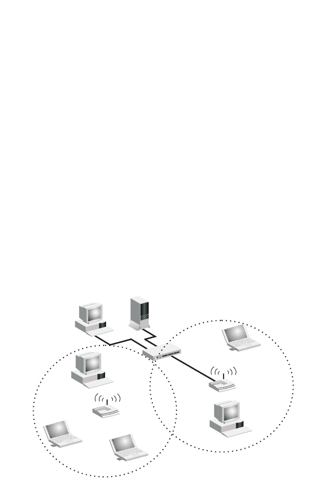
Roaming Wireless PCs
A wireless infrastructure can also support roaming for mobile
workers. More than one access point can be configured to create
an Extended Service Set (ESS). By placing the access points so that
a continuous coverage area is created, wireless users within this
ESS can roam freely. All wireless adapters and access points within
a specific ESS must be configured with the same SS ID and to the
same radio channel.
File
Server
Switch
Desktop PC
Access Point
Notebooks with Wireless
PC Card Adapters
Seamless Roaming
<BSS2>
<ESS>
<BSS1>
PC with Wireless
PC I Adapter
PC with Wireless
PCI Adapter
Notebook with Wireless
PC Card Adapter
Access Point
Wireless Cell
Coverage Area


T
ROUBLESHOOTING
18
T
ROUBLESHOOTING
Check the following troubleshooting items before contacting SMC
Technical Support.
Adapter Installation Problems
If your computer cannot find the EZ Connect Wireless PC Card or
the network driver does not install correctly, check the following:
•Make sure the adapter is securely seated in the PCMCIA slot.
When you insert the wireless adapter into the notebook’s slot,
a beep should be heard if the adapter is properly inserted.
Check for any hardware problems, such as physical damage to
the card’s connector.
•Try the card in another PCMCIA slot. If this also fails, test your
computer with another SMC2632W V.2 Wireless PC Card that is
known to operate correctly.
•When operating under Windows NT, make sure a PCMCIA card
and socket services driver is installed in your computer. Also
check for resource conflicts using the Windows NT Diagnostics
utility.
•Make sure your computer is using the latest BIOS.
•If there are other network adapters in the computer, they may
be causing conflict. Remove all other adapters from the
computer and test the wireless adapter separately.

N
ETWORK
C
ONNECTION
P
ROBLEMS
19
•Check for a defective computer or PCMCIA connection by
trying the adapter in another computer that is known to operate
correctly.
•If it still does not work, take out the wireless adapter. Delete
CW10.sys from c:\windows\system. Then go to “Control
Panel” and delete the adapter from your network configuration
menu. Restart your PC and reinstall the card.
Network Connection Problems
If the Link LED on the PC Card does not light, or if you cannot
access any network resources from the computer, check the
following:
•Make sure the correct software driver is installed for your
operating system. If necessary, try reinstalling the driver.
•Make sure the computer and other network devices are
receiving power.
•The access point you want to attach to may be defective. Try
using another access point.
•If you cannot access a Windows or NetWare service on the
network, check that you have enabled and configured the
service correctly. If you cannot connect to a particular server,
be sure that you have access rights and a valid ID and
password.
•If you cannot access the Internet, be sure you have configured
your system for TCP/IP.

20
If your wireless station cannot communicate with a computer in
the Ethernet LAN when configured for Infrastructure mode, check
the following:
•Make sure the access point which the station is associated with
is powered on.
•If you still can’t connect, change the access point and all the
stations within the BSS to another radio channel.
•Make sure the SSID is the same as that used by the acess point
for a station with roaming disabled, or the same as that used by
the access points in the extended service set (ESS).

N
ETWORK
C
ONNECTION
P
ROBLEMS
21
SMC Networks
802.11b Wireless Product Maximum Distance Table
Important Notice
Maximum distances posted below are actual tested distance
thresholds. However, there are many variables such as barrier
composition and construction, as well as local environmental
interference that may impact your actual distances and cause you
to experience distance thresholds far lower than those posted
below. If you have any questions or comments regarding the
features or performance of this product, or if you would like
information regarding our full line of wireless products, you can
visit us at www.smc.com, or you can call us toll-free at
800.SMC.4YOU. SMC Networks stands behind every product sold
with a 30-day satisfaction guarantee and a limited-lifetime
warranty.
SMC Wireless Product Maximum Distance Table
Speed and Distance Ranges
Environmental Condition 11 Mbps 5.5 Mbps 2 Mbps 1 Mbps
Open Environment: A
line-of-sight environment
with no interference or
obstruction between the
access point and users.
160 m
(520 ft) 270 m
(880 ft) 400 m
(1300 ft) 450 m
(1500 ft)
Semi-Open Environment:
An environment with no
major obstructions such as
walls or privacy cubicles
between the access point
and users.
50 m
(160 ft) 70 m
(230 ft) 90 m
(300 ft) 120 m
(400 ft)
Closed Environment: A
typical office or home
environment with floor to
ceiling obstructions between
the access point and
users.
25 m
(80 ft) 35 m
(120 ft) 45 m
(150 ft) 55 m
(180 ft)

S
PECIFICATIONS
22
S
PECIFICATIONS
General Specifications
Functional Criteria
Data Rate 1, 2, 5.5, 11 Mbps
Transmission Mode Half duplex
Network Connection IEEE 802.11b - Wireless LAN,
Operating Range Up to 350 m (1155 ft) at 1 Mbps,
Up to 160 m (528 ft) at 11 Mbps (indoor)
Radio Signal
Signal Type Direct Sequence Spread-Spectrum (DSSS)
Operating Frequency USA, Canada and Europe (ETSI):
2.400-2.4835 GHz,
Japan: 2.400-2.497 GHz
Sensitivity -76 dBm (typical)
Modulation CCK, BPSK, QPSK
Output Power Less than 15dBm
Physical Characteristics
Power Consumption 5 V, 380 mA transmit, 290 mA receive
(normal)
Dimensions Type II PC Card + antenna 12.8 x 5.3 cm
(5.04 x 2.09 in.)
Antenna Antenna diversity
LED Indicator Power, Link, Activity
Host Interface PCMCIA, Type II

S
OFTWARE
D
RIVERS
23
Standards Conformance
Wireless Standard IEEE 802.11b
Environmental
Temperature Operating: 0 to 50 °C (32 to 122 °F)
Storage: 0 to 70 °C (32 to 158 °F)
Humidity 5 to 80% (noncondensing)
Vibration/Shock/Drop IEC 68-2-34, IEC 68-2-27, IEC68-2-32
Certification
CE Mark EN50081-1, EN55022 Class B
EN50082-1, IEC 61000-4-2/3/4/6/11
Emissions FCC Part 15(B), ETS 300-328, VCCI
Safety EN60950
UL1950/CSA22.2 No.950
Software Drivers
NDIS Drivers Windows 95 OSR2.1 or above version
Windows 98
Windows Me
Windows NT 4.0
Windows 2000
Windows XP

24
T
ERMINOLOGY
The following is a list of terminology that is used in this document.
Access Point – An internetworking device that seamlessly
connects wired and wireless networks.
Ad Hoc – An ad hoc wireless LAN is a group of computers, each
with LAN adapters, connected as an independent wireless LAN.
Backbone – The core infrastructure of a network. The portion of
the network that transports information from one central location
to another central location where it is unloaded onto a local
system.
Base Station – In mobile telecommunications, a base station is the
central radio transmitter/receiver that maintains communications
with the mobile radiotelephone sets within its range. In cellular
and personal communications applications, each cell or micro-cell
has its own base station; each base station in turn is
interconnected with other cells’ bases.
BSS – BSS stands for “Basic Service Set.” It is an Access Point and
all the LAN PCs that are associated with it.
CSMA/CA – Carrier Sense Multiple Access with Collision
Avoidance.
ESS – ESS (ESS-ID, SSID) stands for “Extended Service Set.” More
than one BSS is configured to become an Extended Service Set.
LAN mobile users can roam between different BSSs in an ESS
(ESS-ID, SSID).

T
ERMINOLOGY
25
Ethernet – A popular local area data communications network,
which accepts transmission from computers and terminals.
Ethernet operates on a 10 Mbps baseband transmission rate, using
shielded coaxial cable or shielded twisted-pair telephone cable.
Infrastructure – An integrated wireless and wired LAN is called
an Infrastructure configuration.
Roaming – A wireless LAN mobile user moves around an ESS and
maintains a continuous connection to the Infrastructure network.
RTS Threshold – Transmitters contending for the medium may
not be aware of each other. The RTS/CTS mechanism can solve
this “Hidden Node Problem.” If the packet size is smaller than the
preset RTS Threshold size, the RTS/CTS mechanism will NOT be
enabled.
WEP – “Wired Equivalent Privacy” is based on the use of 64-bit or
128-bit keys and the popular RC4 encryption algorithm. Wireless
devices without a valid WEP key will be excluded from network
traffic.

T
ERMINOLOGY
26

38 Tesla
Irvine, CA 92618
Phone: (949) 679-8000
FOR TECHNICAL SUPPORT, CALL:
From U.S.A. and Canada (24 hours a day, 7 days a week)
(800) SMC-4-YOU; (949) 679-8000; Fax: (949) 679-1481
From Europe (8:00 AM - 5:30 PM UK Time)
44 (0) 118 974 8700; Fax: 44 (0) 118 974 8701
INTERNET
E-mail addresses:
techsupport@smc.com
european.techsupport@smc-europe.com
Driver updates:
http://www.smc.com/index.cfm?action=tech_support_drivers_downloads
World Wide Web:
http://www.smc.com/
http://www.smc-europe.com/
FOR LITERATURE OR ADVERTISING RESPONSE, CALL:
U.S.A. and Canada: (800) SMC-4-YOU; Fax (949) 679-1481
Spain: 34-93-477-4935; Fax 34-93-477-3774
UK: 44 (0) 118 974 8700; Fax 44 (0) 118 974 8701
France: 33 (0) 41 38 32 32; Fax 33 (0) 41 38 01 58
Italy: 39 02 739 12 33; Fax 39 02 739 14 17
Benelux: 31 33 455 72 88; Fax 31 33 455 73 30
Central Europe: 49 (0) 89 92861-0; Fax 49 (0) 89 92861-230
Switzerland: 41 (0) 1 9409971; Fax 41 (0) 1 9409972
Nordic: 46 (0) 868 70700; Fax 46 (0) 887 62 62
Northern Europe: 44 (0) 118 974 8700; Fax 44 (0) 118 974 8701
Eastern Europe: 34 -93-477-4920; Fax 34 93 477 3774
Sub Saharian Africa: 27-11 314 1133; Fax 27-11 314 9133
North Africa: 34 93 477 4920; Fax 34 93 477 3774
Russia: 7 (095) 290 29 96; Fax 7 (095) 290 29 96
PRC: 86-10-6235-4958; Fax 86-10-6235-4962
Taiwan: 886-2-2659-9669; Fax 886-2-2659-9666
Asia Pacific: (65) 238 6556; Fax (65) 238 6466
Korea: 82-2-553-0860; Fax 82-2-553-7202
Japan: 81-45-224-2332; Fax 81-45-224-2331
Australia: 61-2-9416-0437; Fax 61-2-9416-0474
India: 91-22-8204437; Fax 91-22-8204443
If you are looking for further contact information, please visit www.smc.com or
www.smc-europe.com.
Model Number: SMC2632W V.2
Revision Number: F1.0 E042002-R01