Accton Technology E21011 Draft 11n Dual band Wireless Access Point User Manual user guide
Accton Technology Corp Draft 11n Dual band Wireless Access Point user guide
UserManual.wiki
>
Accton Technology
>
E21011 User Manual
User manual
Navigation menu
Upload a User Manual
Namespaces
Wiki Guide
HTML
PDF
Info
Views
User Manual
Discussion / Help
Navigation


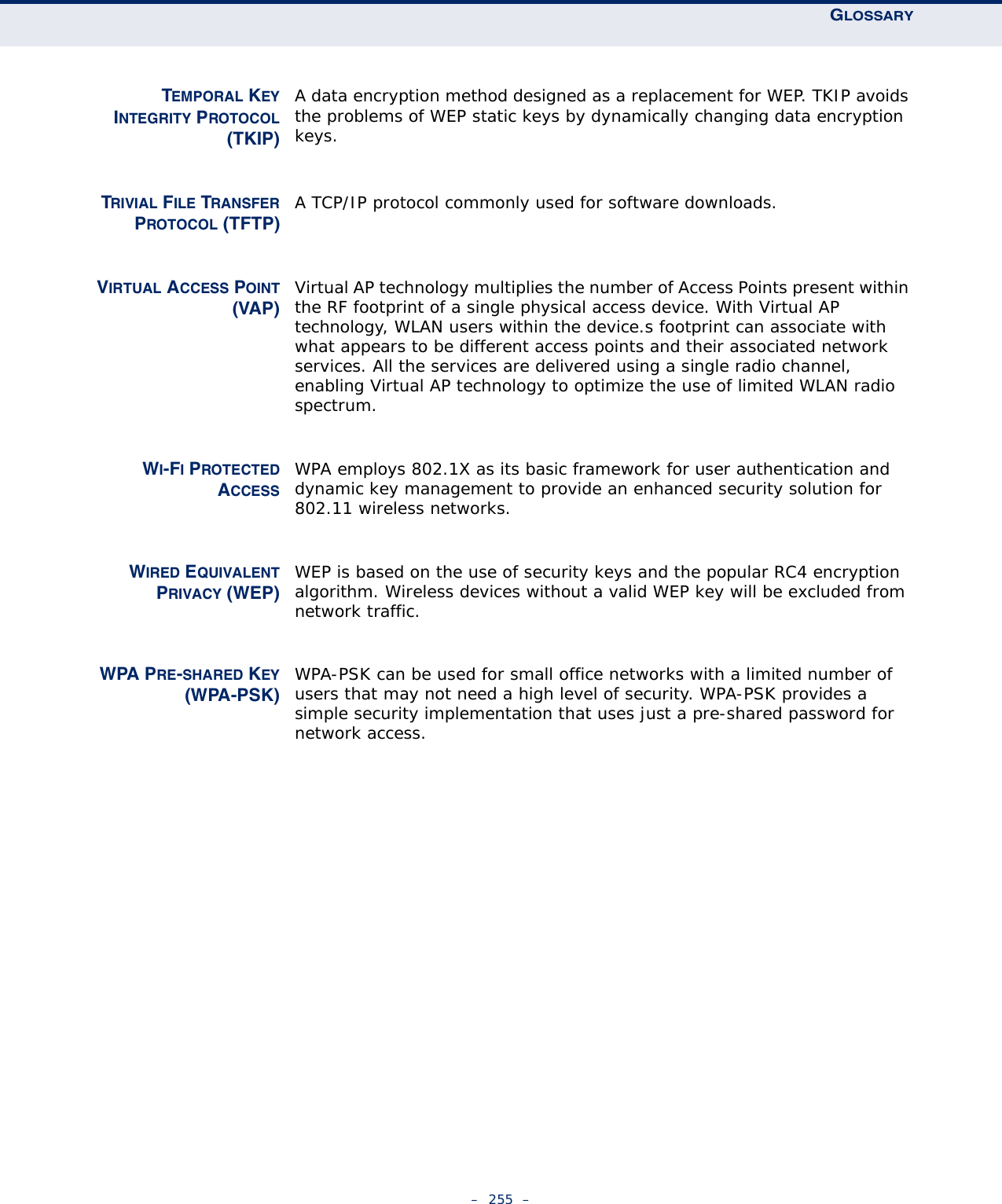
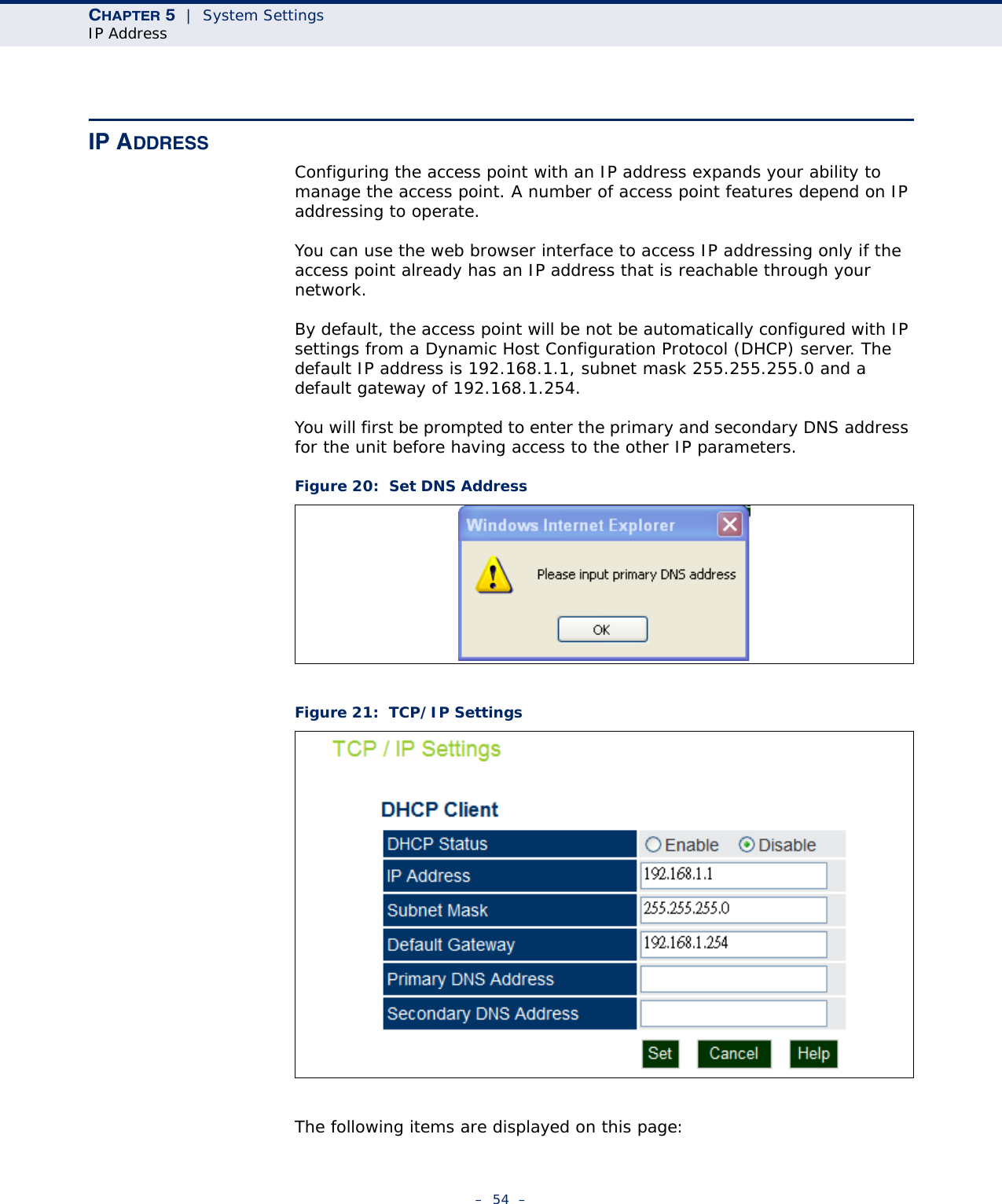
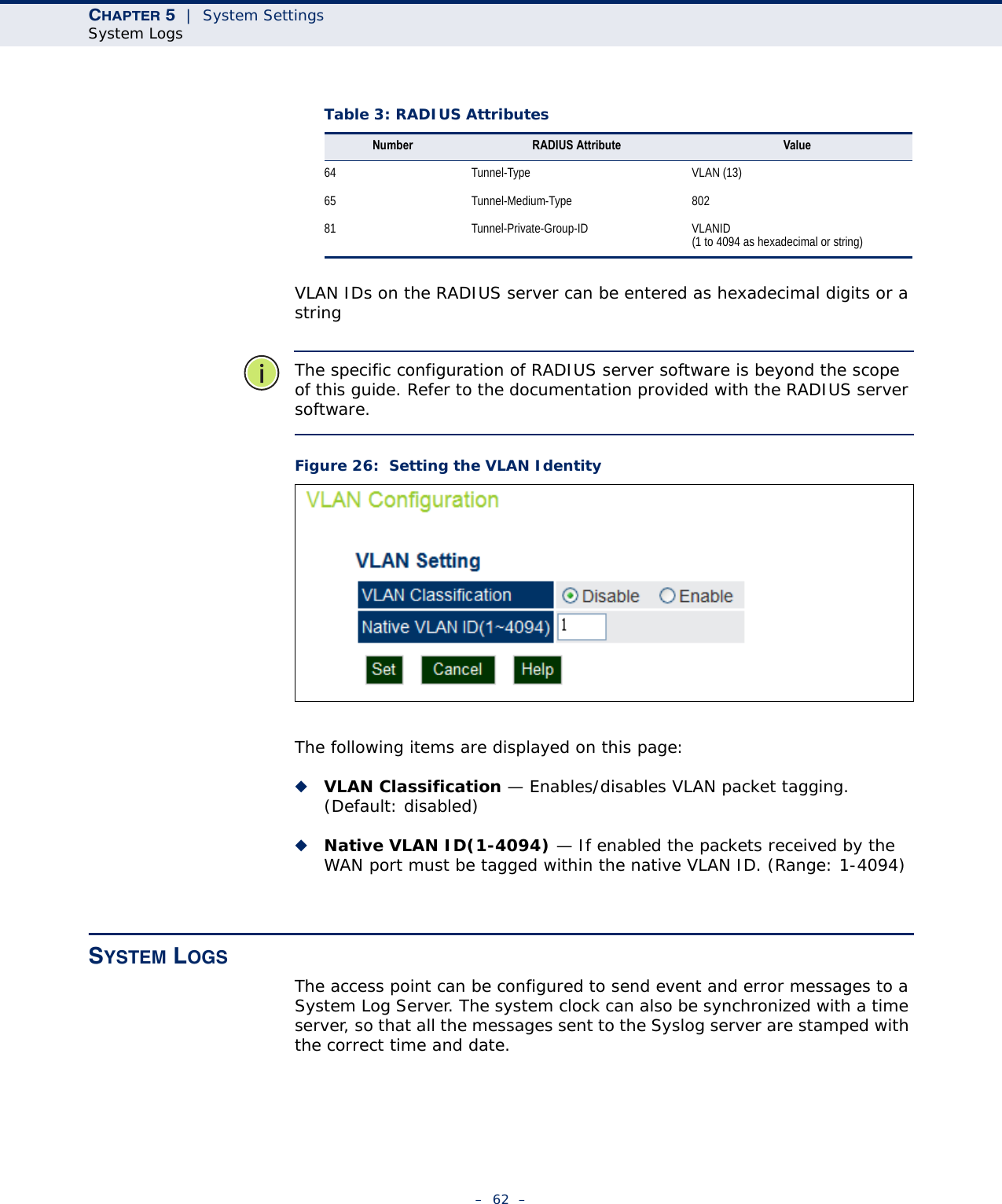
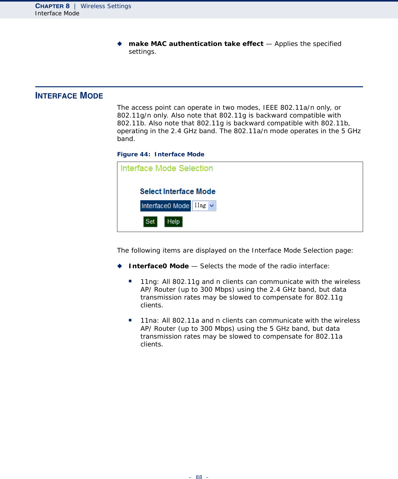
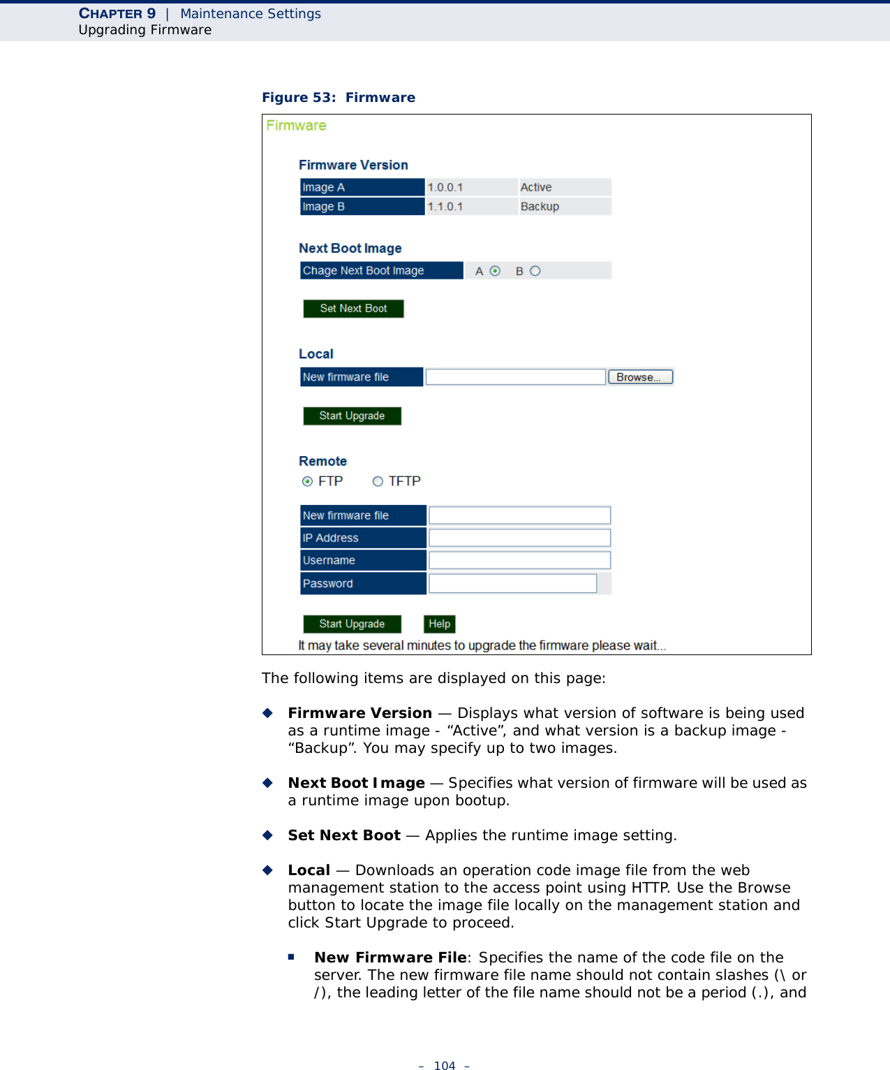
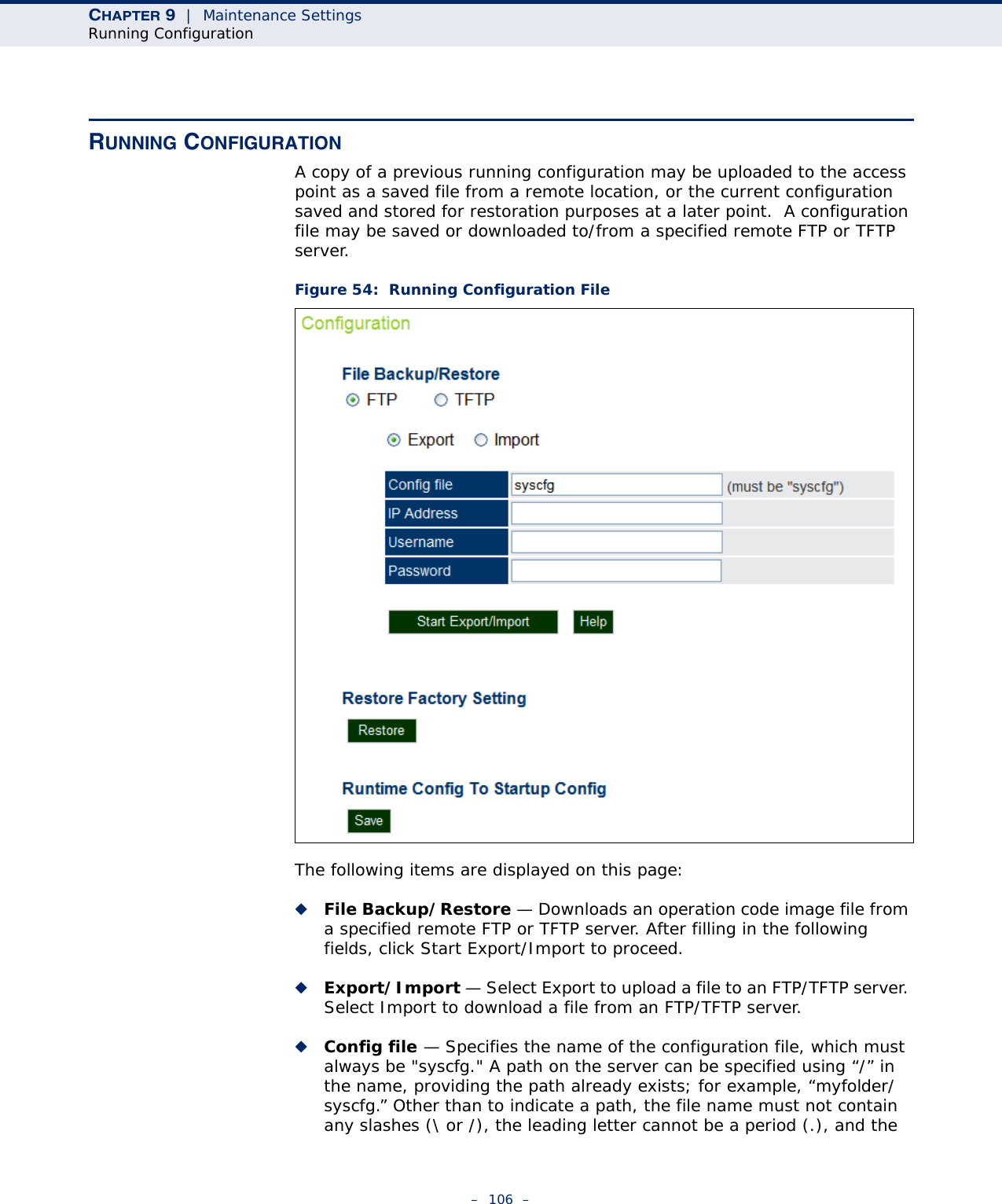
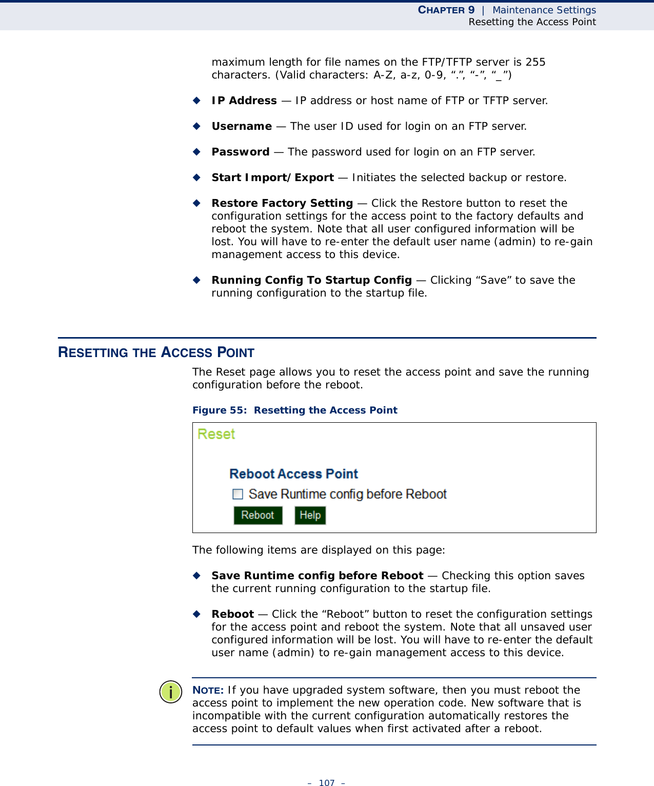
![ABOUT THIS GUIDE– 8 –IMPORTANT NOTE:FCC RADIATION EXPOSURE STATEMENTThis equipment complies with FCC radiation exposure limits set forth for an uncontrolled environment. This equipment should be installed and operated with minimum distance 20 cm between the radiator & your body.IC STATEMENT :This Class B digital apparatus complies with Canadian ICES-003.Operation is subject to the following two conditions: (1) this device may not cause interference, and (2) this device must accept any interference, including interference that may cause undesired operation of the device.Cet appareil numérique de la classe B conforme á la norme NMB-003 du Canada.To reduce potential radio interference to other users, the antenna type and its gain should be so chosen that the equivalent isotropically radiated power (e.i.r.p) is not more than that permitted for successful communication.This device has been designed to operate with the antennas listed below, and having a maximum gain of [5] dB. Antennas not included in this list or having a gain greater than [5] dB are strictly prohibited for use with this device. The required antenna impedance is 50 ohms.The device could automatically discontinue transmission in case of absence of information to transmit, or operational failure. Note that this is not intended to prohibit transmission of control or signaling information or the use of repetitive codes where required by the technology.The device for the band 5150-5250 MHz is only for indoor usage to reduce potential for harmful interference to co-channel mobile satellite systems.The maximum antenna gain permitted (for devices in the band 5725-5825 MHz) to comply with the e.i.r.p. limits specified for point-to-point and non point-to-point operation as appropriate, as stated in section A9.2(3).IMPORTANT NOTE:IC Radiation Exposure Statement:This equipment complies with IC RSS-102 radiation exposure limits set forth for an uncontrolled environment. This equipment should be installed and operated with minimum distance 20 cm between the radiator & your body.](https://usermanual.wiki/Accton-Technology/E21011/User-Guide-1097647-Page-8.png)

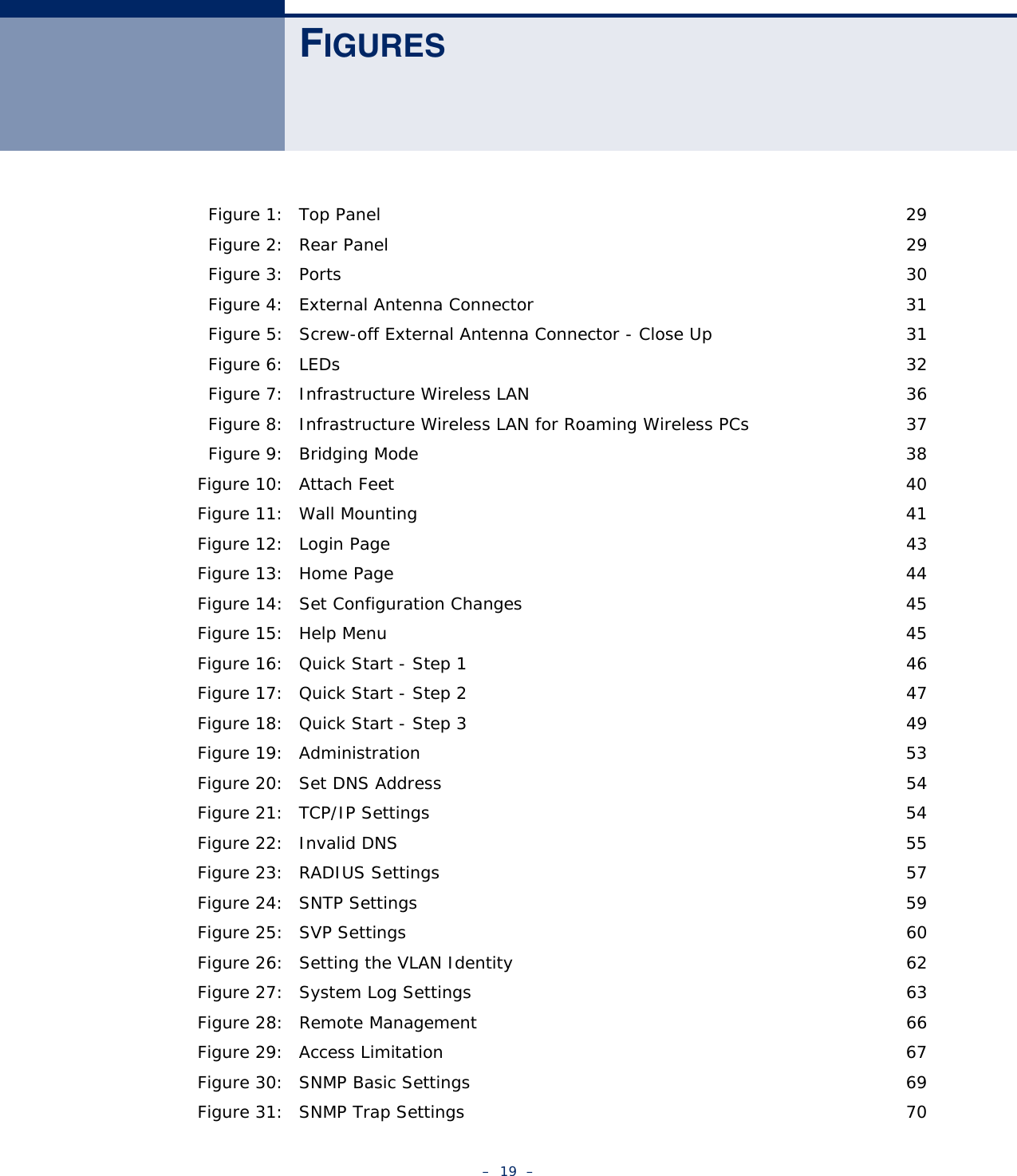


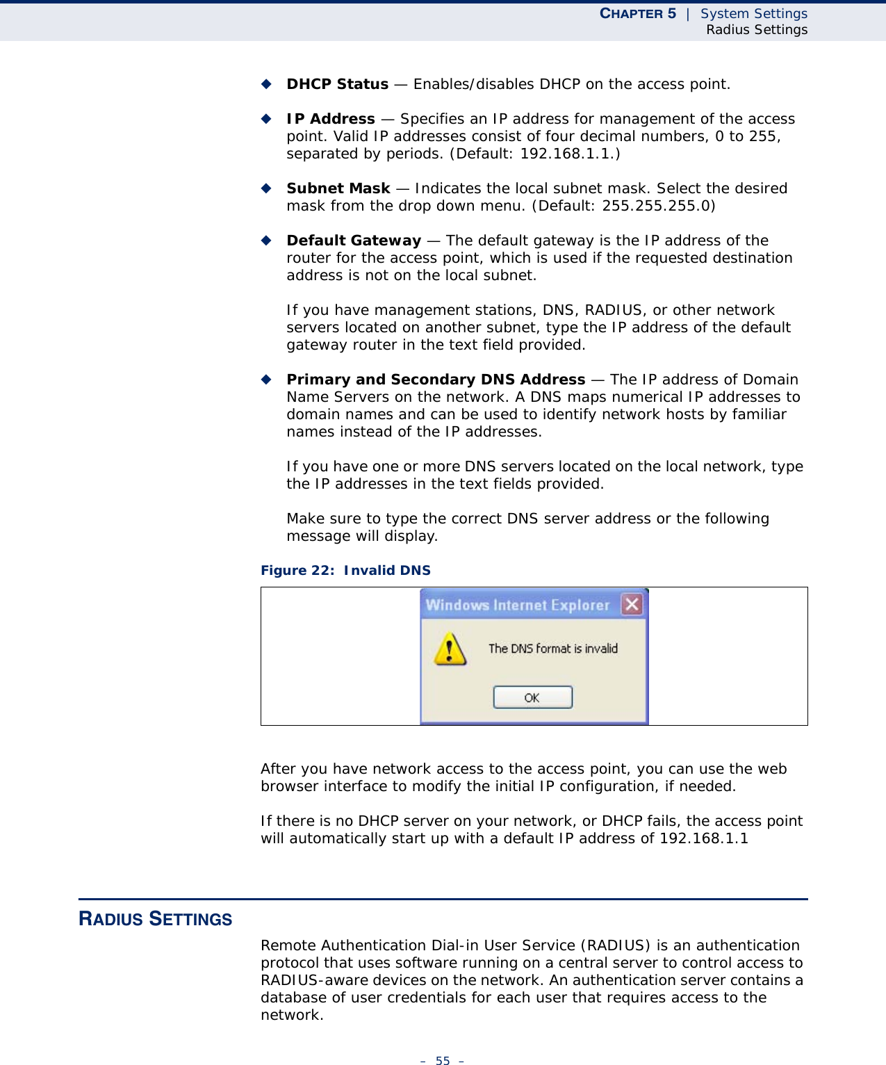
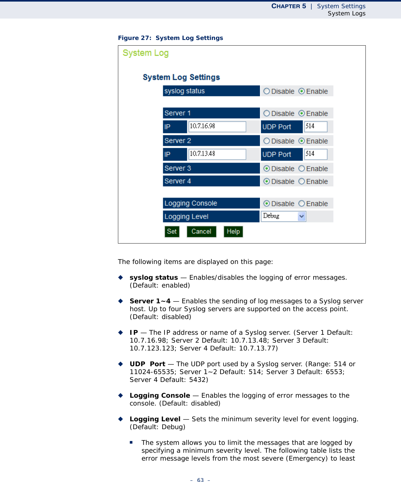
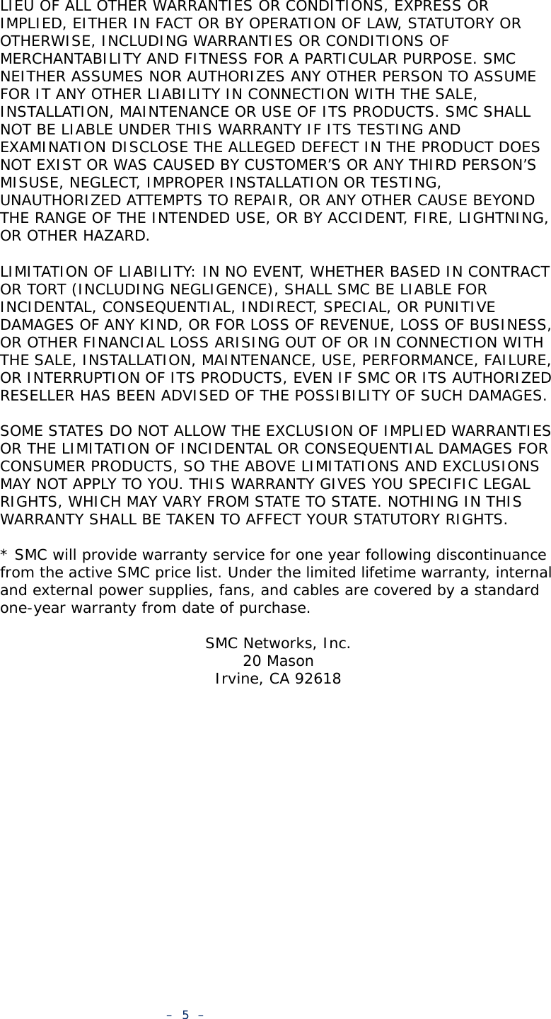
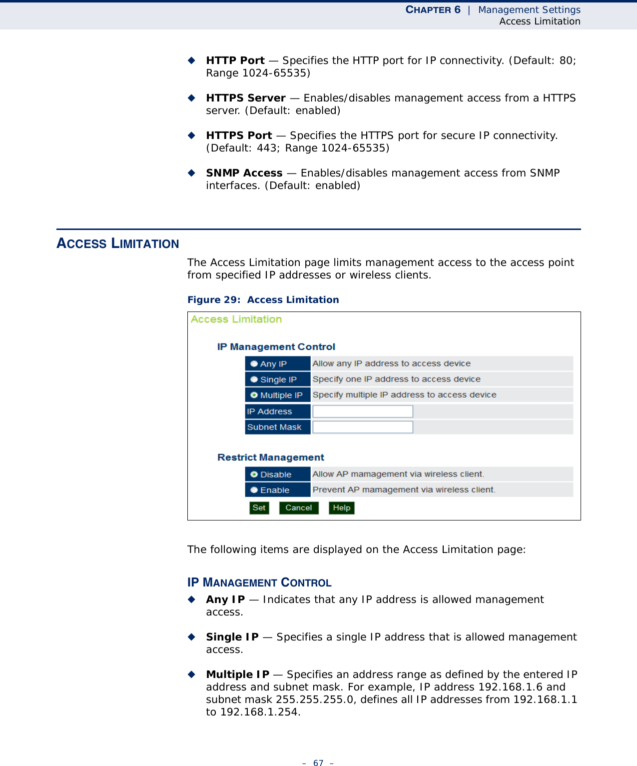
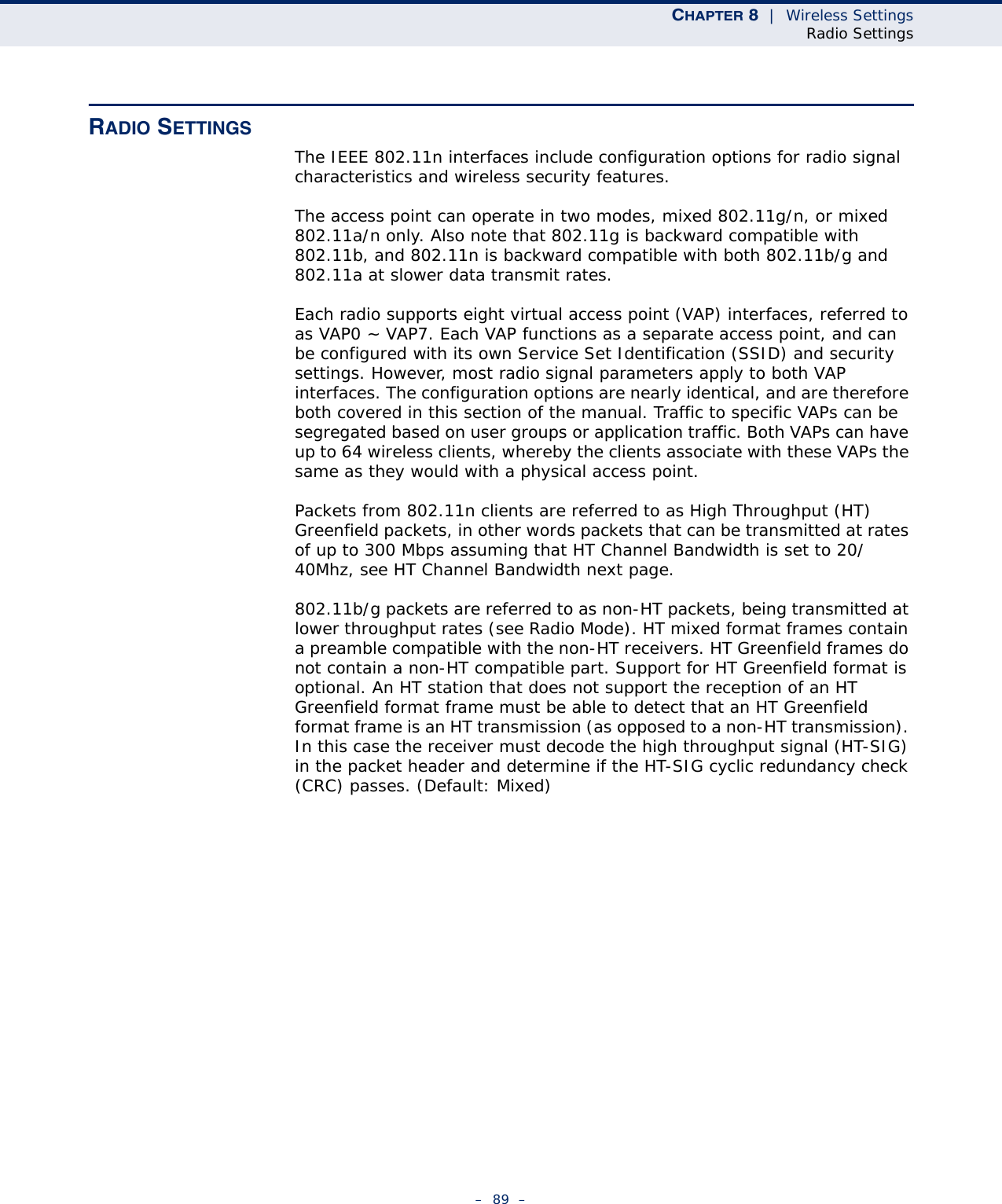
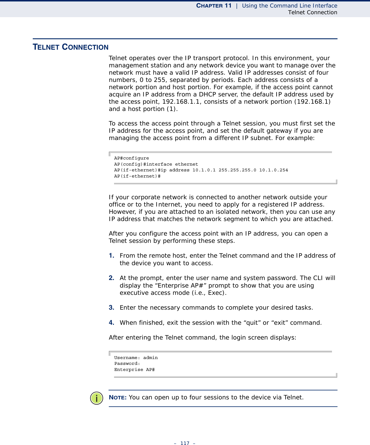
![– 65 –6MANAGEMENT SETTINGSThis chapter describes management access settings on the access point. It includes the following sections:◆“Remote Management Settings” on page 65◆“Access Limitation” on page 67◆“Simple Network Management Protocol” on page 68REMOTE MANAGEMENT SETTINGSThe Web, Telnet, and SNMP management interfaces are enabled and open to all IP addresses by default. To provide more security for management access to the access point, specific interfaces can be disabled and management restricted to a single IP address or a limited range of IP addresses.Once you specify an IP address or range of addresses, access to management interfaces is restricted to the specified addresses. If anyone tries to access a management interface from an unauthorized address, the access point will reject the connection.Telnet is a remote management tool that can be used to configure the access point from anywhere in the network. However, Telnet is not secure from hostile attacks. The Secure Shell (SSH) can act as a secure replacement for Telnet. The SSH protocol uses generated public keys to encrypt all data transfers passing between the access point and SSH-enabled management station clients and ensures that data traveling over the network arrives unaltered. Clients can then securely use the local user name and password for access authentication.Note that SSH client software needs to be installed on the management station to access the access point for management via the SSH protocol.Both HTTP and HTTPS service can be enabled independently. If you enable HTTPS, you must indicate this in the URL: https://device:port_number]When you start HTTPS, the connection is established in this way:◆The client authenticates the server using the server’s digital certificate.◆The client and server negotiate a set of security protocols to use for the connection.](https://usermanual.wiki/Accton-Technology/E21011/User-Guide-1097647-Page-65.png)
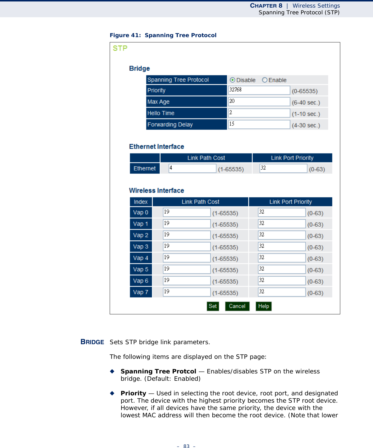
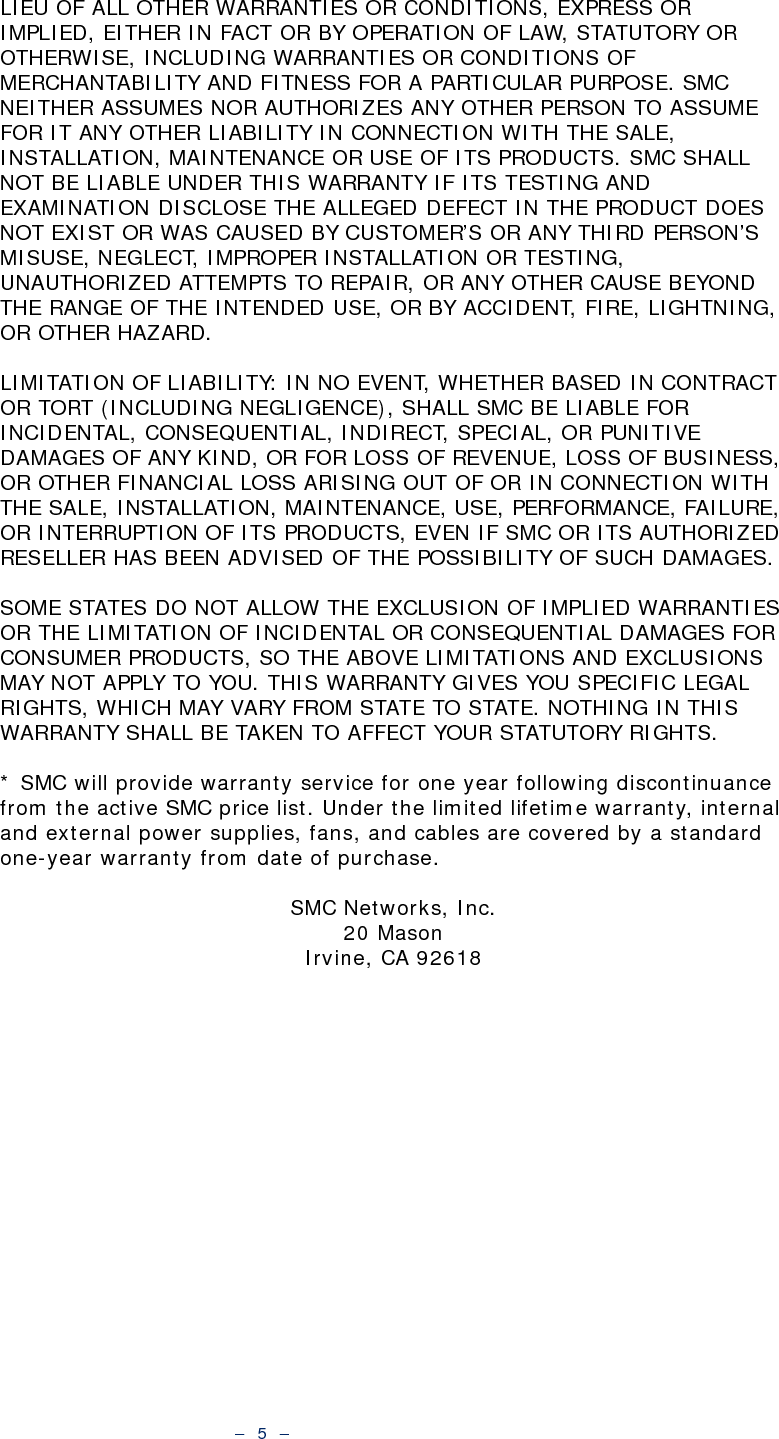
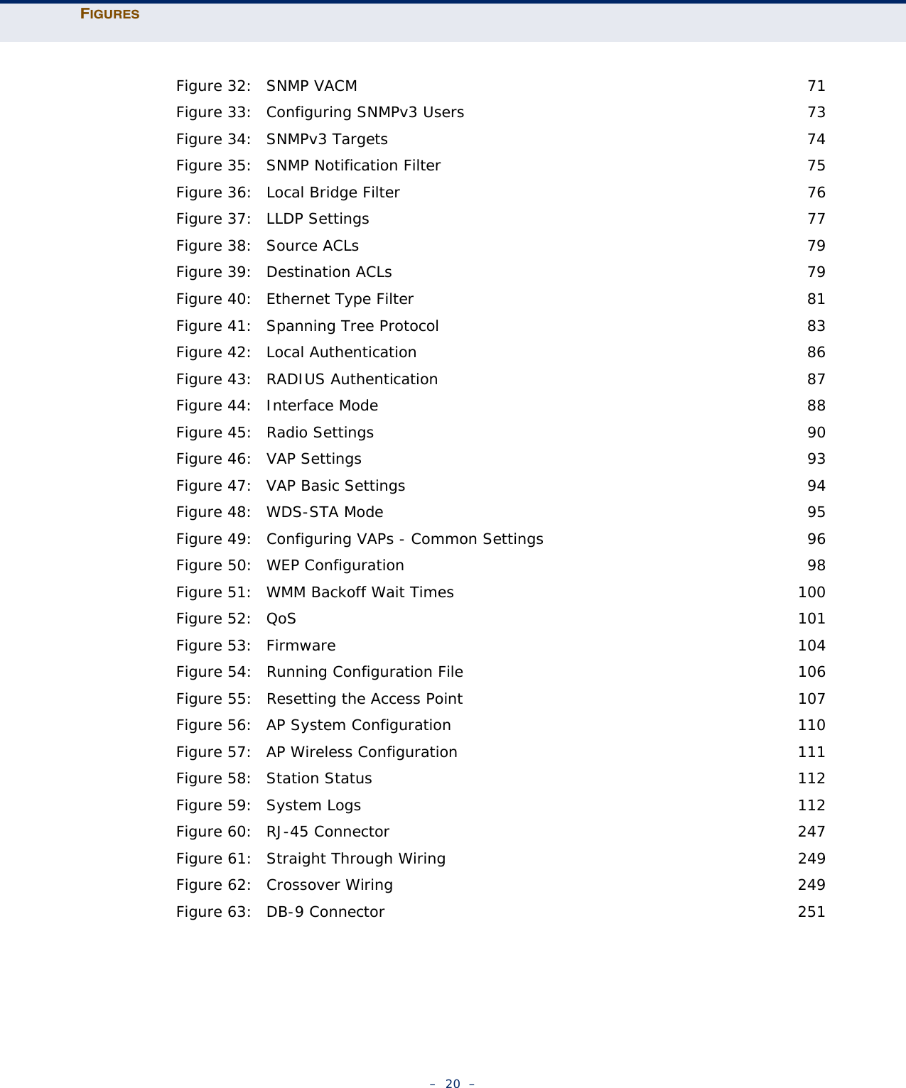
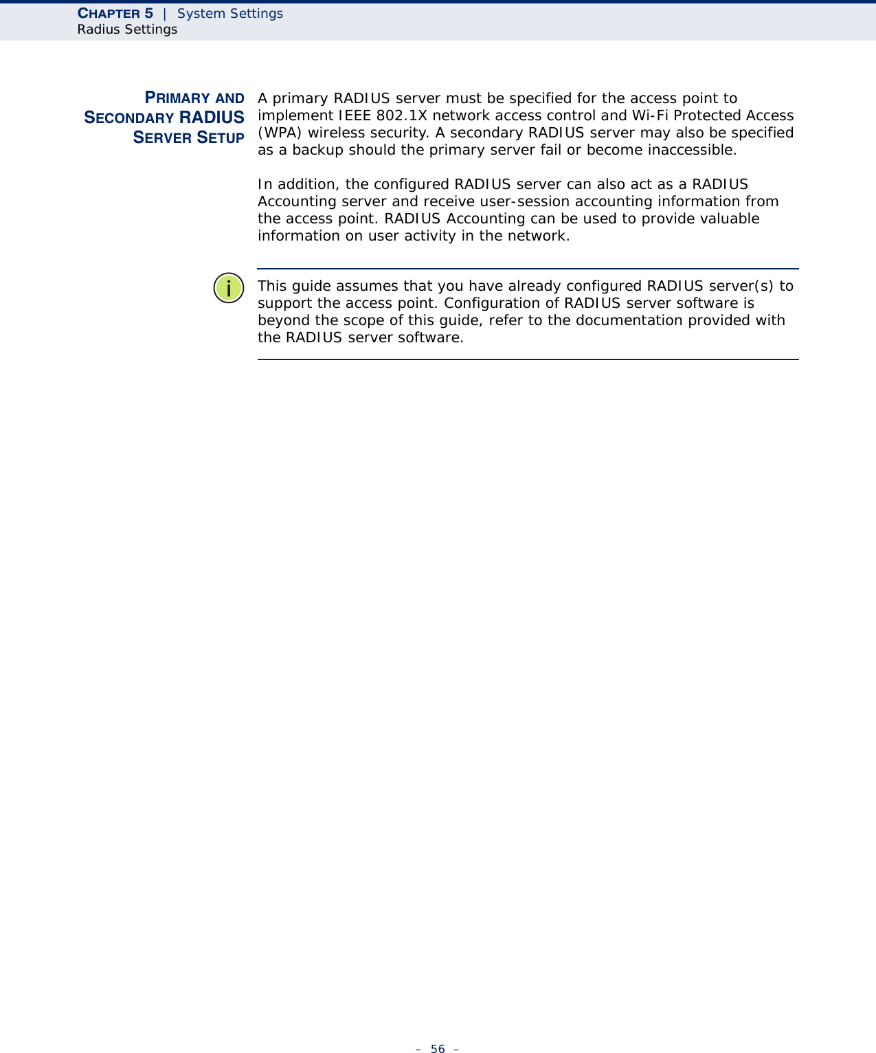
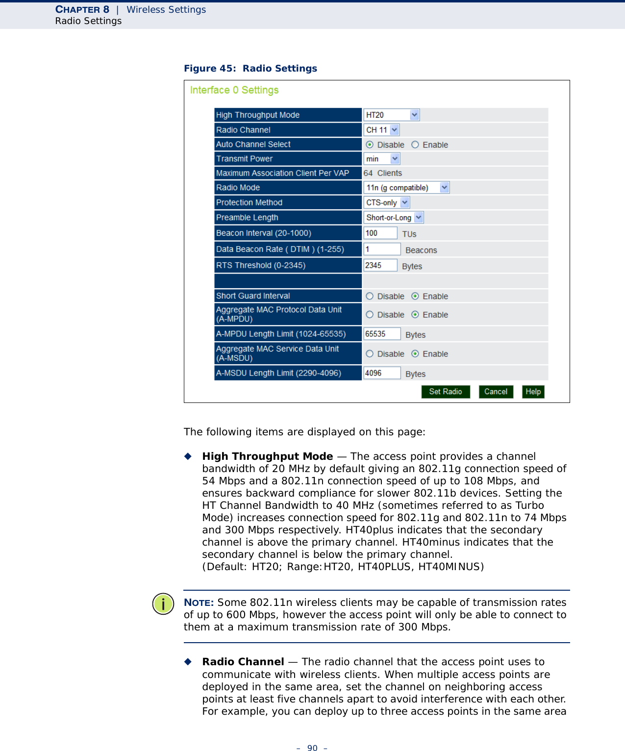
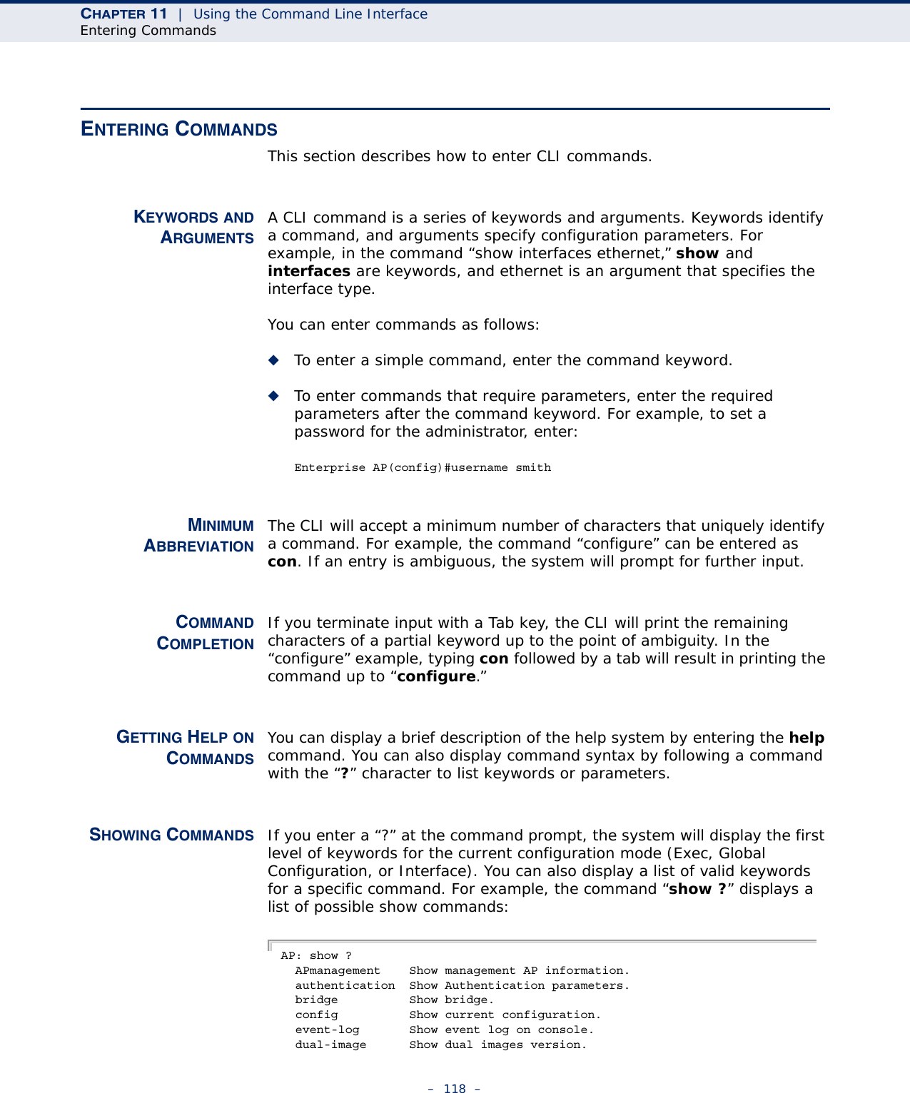
![CHAPTER 8 | Wireless SettingsSpanning Tree Protocol (STP)– 84 –numeric values indicate higher priority.) (Default:32768; Range: 0-65535)◆Max Age — The maximum time (in seconds) a device can wait without receiving a configuration message before attempting to reconfigure. All device ports (except for designated ports) should receive configuration messages at regular intervals. Any port that ages out STP information (provided in the last configuration message) becomes the designated port for the attached LAN. If it is a root port, a new root port is selected from among the device ports attached to the network. (Default: 20 seconds; Range: 6-40 seconds)■Minimum: The higher of 6 or [2 x (Hello Time + 1)].■Maximum: The lower of 40 or [2 x (Forward Delay - 1)]◆Hello Time — Interval (in seconds) at which the root device transmits a configuration message. (Default: 2 seconds; Range: 1-10 seconds)■Minimum: 1■Maximum: The lower of 10 or [(Max. Message Age / 2) -1]◆Forwarding Delay — The maximum time (in seconds) this device waits before changing states (i.e., discarding to learning to forwarding). This delay is required because every device must receive information about topology changes before it starts to forward frames. In addition, each port needs time to listen for conflicting information that would make it return to a discarding state; otherwise, temporary data loops might result. (Default: 15 seconds; Range: 4-30 seconds)■Minimum: The higher of 4 or [(Max. Message Age / 2) + 1]■Maximum: 30ETHERNET INTERFACE Sets STP settings for the Ethernet port.◆Link Path Cost — This parameter is used by the STP to determine the best path between devices. Therefore, lower values should be assigned to ports attached to faster media, and higher values assigned to ports with slower media. (Path cost takes precedence over port priority.) (Default: Ethernet interface: 19; Wireless interface: 40; Range: 1-65535◆Link Port Priority — Defines the priority used for this port in the Spanning Tree Protocol. If the path cost for all ports on a switch are the same, the port with the highest priority (i.e., lowest value) will be configured as an active link in the spanning tree. This makes a port with higher priority less likely to be blocked if the Spanning Tree Protocol is detecting network loops. Where more than one port is assigned the highest priority, the port with lowest numeric identifier will be enabled. (Default: 128; Range: 0-240, in steps of 16)](https://usermanual.wiki/Accton-Technology/E21011/User-Guide-1097647-Page-84.png)
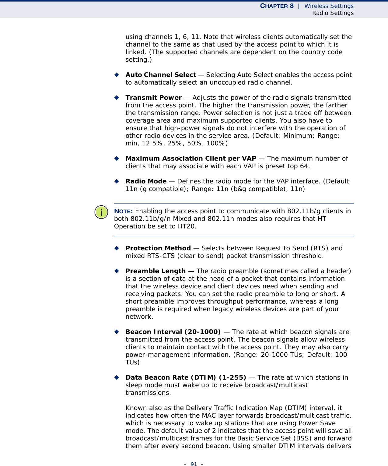


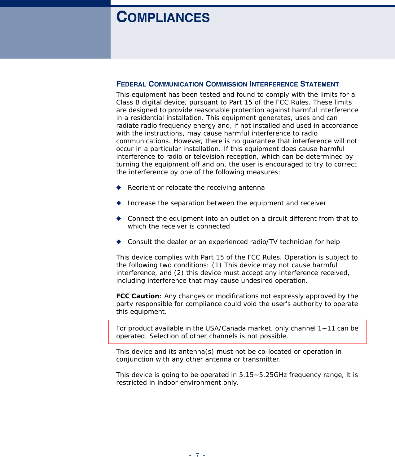
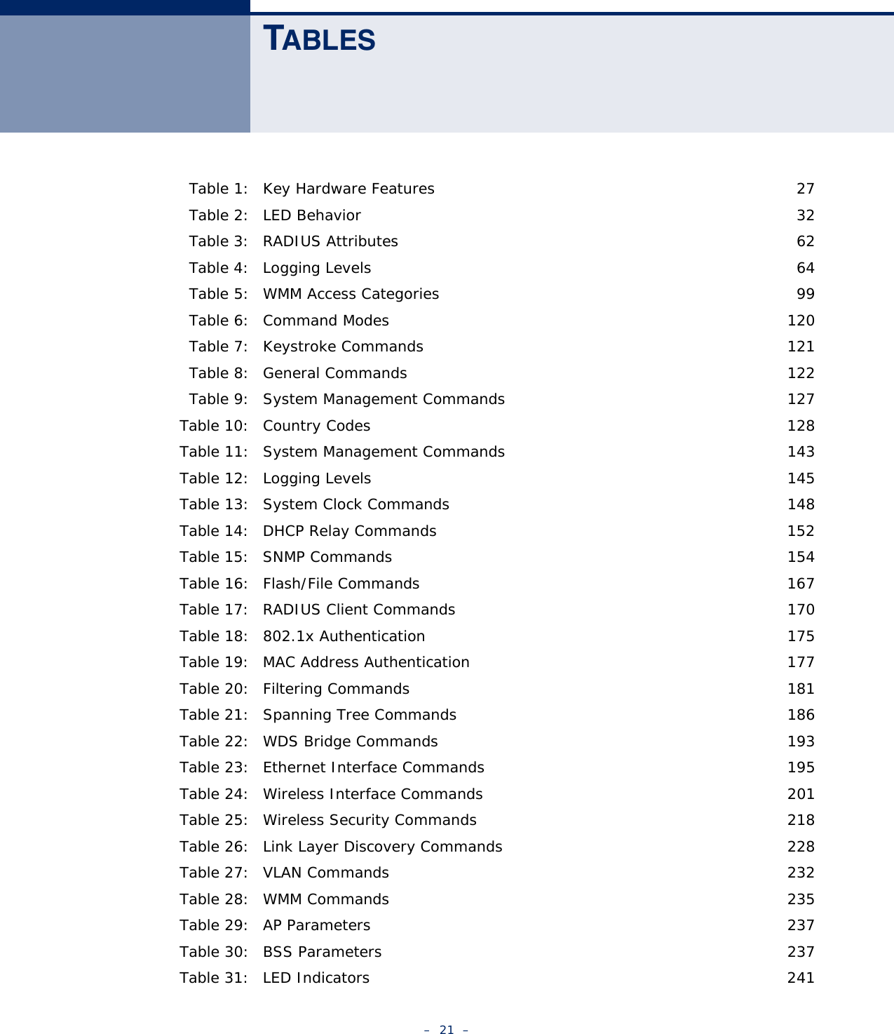
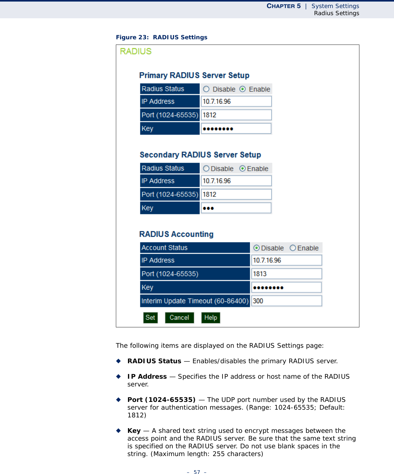
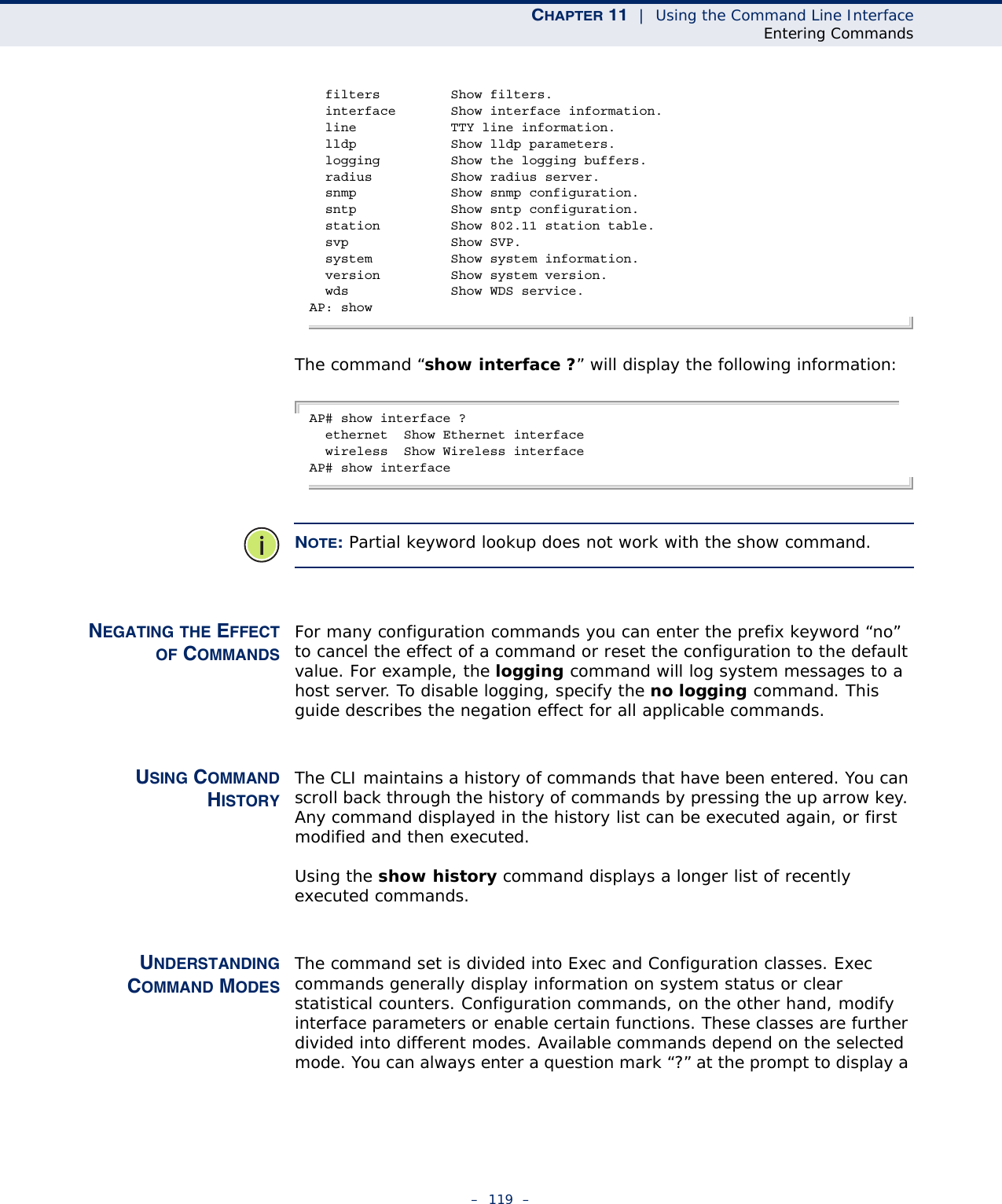
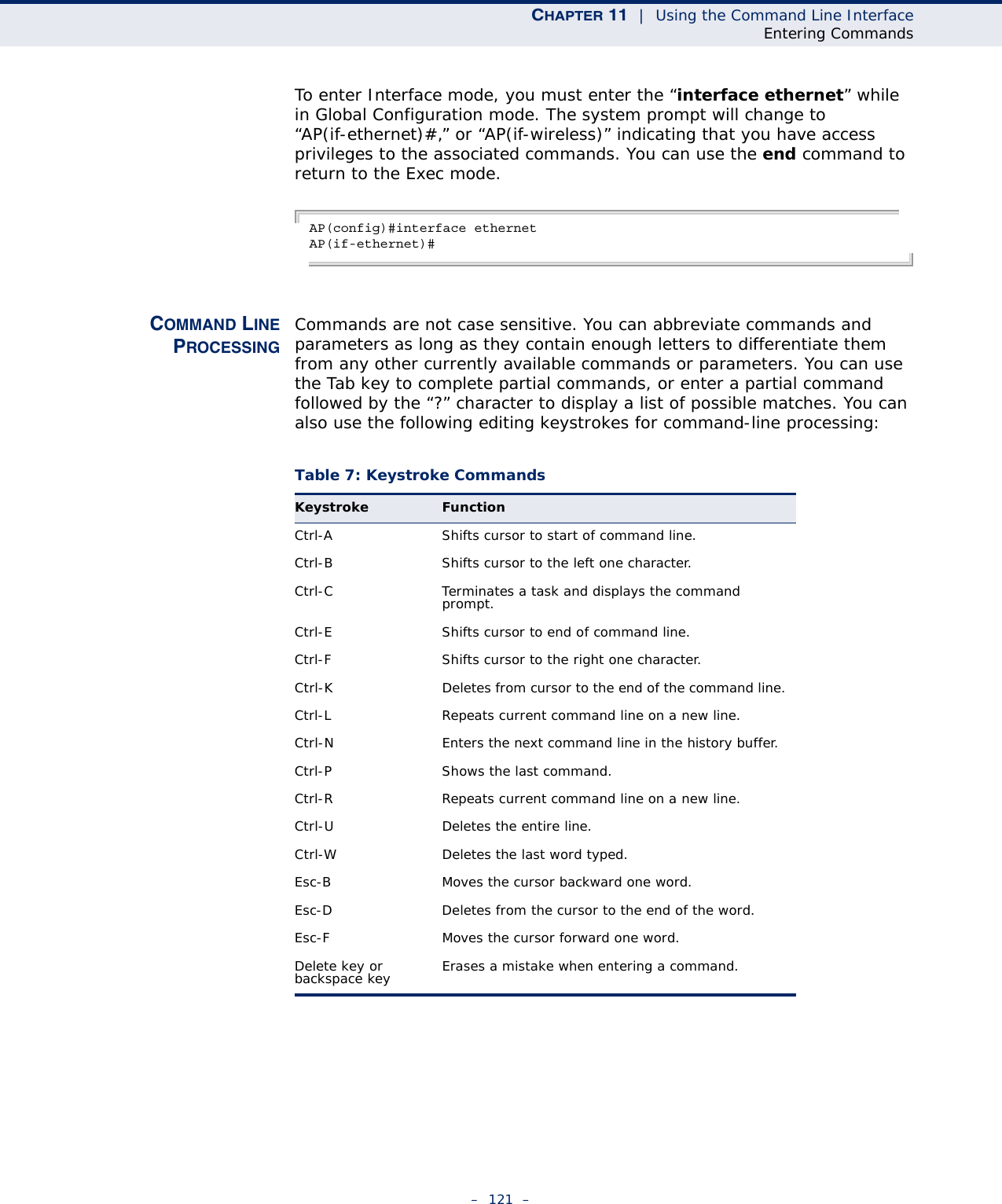
![– 116 –11 USING THE COMMAND LINE INTERFACEWhen accessing the management interface for the over a direct connection to the console port, or via a Telnet connection, the access point can be managed by entering command keywords and parameters at the prompt. Using the access point’s command-line interface (CLI) is very similar to entering commands on a UNIX system.CONSOLE CONNECTIONTo access the access point through the console port, perform these steps:At the console prompt, enter the user name and password. (The default user name is “admin” and the default password is “smcadmin”) When the user name is entered, the CLI displays the “Enterprise AP#” prompt. Enter the necessary commands to complete your desired tasks. When finished, exit the session with the “exit” command.After connecting to the system through the console port, the login screen displaysEXAMPLE(none) login: acctonPassword: 1 03:47:41 login[2222]: root login on `ttyS0'Accton#NOTE: Command examples shown later in this chapter abbreviate the console prompt to “AP” for simplicity.](https://usermanual.wiki/Accton-Technology/E21011/User-Guide-1097647-Page-116.png)
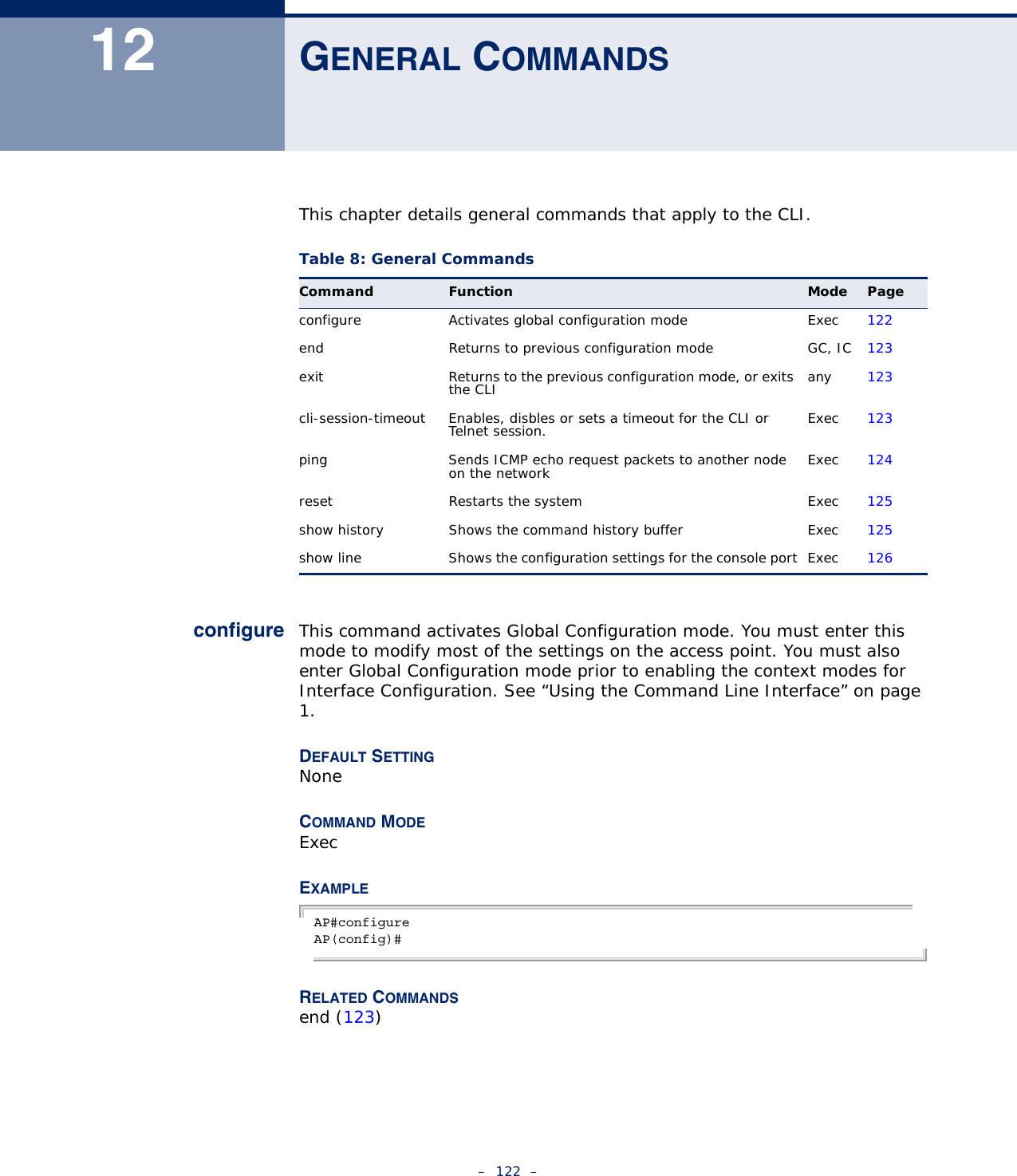
![CHAPTER 11 | Using the Command Line InterfaceEntering Commands– 120 –list of the commands available for the current mode. The command classes and associated modes are displayed in the following table:EXEC COMMANDS When you open a new console session on an access point, the system enters Exec command mode. Only a limited number of the commands are available in this mode. You can access all other commands only from the configuration mode. To access Exec mode, open a new console session with the user name “admin.” The command prompt displays as “Enterprise AP#” for Exec mode.Username: adminPassword: [system login password]AP#CONFIGURATIONCOMMANDSConfiguration commands are used to modify access point settings. These commands modify the running configuration and are saved in memory. The configuration commands are organized into four different modes:◆Global Configuration (GC) - These commands modify the system level configuration, and include commands such as username and password. ◆Interface-Ethernet Configuration (IC-E) - These commands modify the Ethernet port configuration, and include command such as dns and ip.◆Interface-Wireless Configuration (IC-W) - These commands modify the wireless port configuration of global parameters for the radio, and include commands such as channel and transmit-power.◆Interface-Wireless Virtual Access Point Configuration (IC-W-VAP) - These commands modify the wireless port configuration for each VAP, and include commands such as ssid and authentication.To enter the Global Configuration mode, enter the command configure in Exec mode. The system prompt will change to “Enterprise AP(config)#” which gives you access privilege to all Global Configuration commands.AP#configureAP(config)#Table 6: Command ModesClass ModeExec PrivilegedConfiguration GlobalInterface-ethernetInterface-wirelessInterface-wireless-vap](https://usermanual.wiki/Accton-Technology/E21011/User-Guide-1097647-Page-120.png)
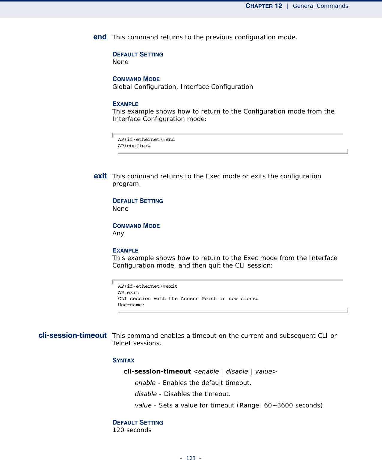
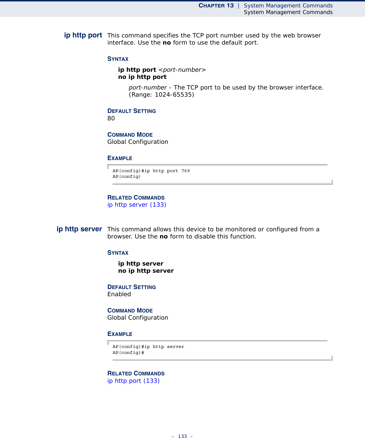
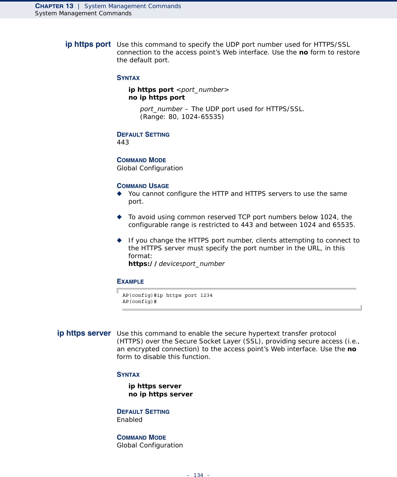
![CHAPTER 13 | System Management CommandsSystem Management Commands– 135 –COMMAND USAGE ◆Both HTTP and HTTPS service can be enabled independently.◆If you enable HTTPS, you must indicate this in the URL: https://device:port_number]◆When you start HTTPS, the connection is established in this way:◆The client authenticates the server using the server’s digital certificate.◆The client and server negotiate a set of security protocols to use for the connection.◆The client and server generate session keys for encrypting and decrypting data.◆The client and server establish a secure encrypted connection.A padlock icon should appear in the status bar for Internet Explorer 5.x.EXAMPLE AP(config)#ip https serverAP(config)#APmgmtIP This command specifies the client IP addresses that are allowed management access to the access point through various protocols.NOTE: Secure Web (HTTPS) connections are not affected by the UI Management or IP Management settings.SYNTAXAPmgmtIP <multiple IP_address subnet_mask | single IP_address | any> multiple - Adds IP addresses within a specifiable range to the SNMP, web and Telnet groups.single - Adds an IP address to the SNMP, web and Telnet groups.any - Allows any IP address access through SNMP, web and Telnet groups.IP_address - Adds IP addresses to the SNMP, web and Telnet groups.subnet_mask - Specifies a range of IP addresses allowed management access.DEFAULT SETTINGAll addresses](https://usermanual.wiki/Accton-Technology/E21011/User-Guide-1097647-Page-135.png)
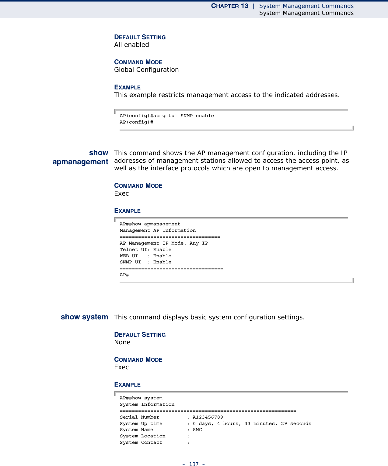
![CHAPTER 13 | System Management CommandsSystem Management Commands– 136 –COMMAND MODEGlobal ConfigurationCOMMAND USAGE◆If anyone tries to access a management interface on the access point from an invalid address, the unit will reject the connection, enter an event message in the system log, and send a trap message to the trap manager.◆IP address can be configured for SNMP, web and Telnet access respectively. Each of these groups can include up to five different sets of addresses, either individual addresses or address ranges.◆When entering addresses for the same group (i.e., SNMP, web or Telnet), the access point will not accept overlapping address ranges. When entering addresses for different groups, the access point will accept overlapping address ranges.◆You cannot delete an individual address from a specified range. You must delete the entire range, and reenter the addresses.◆You can delete an address range just by specifying the start address, or by specifying both the start address and end address.EXAMPLEThis example restricts management access to the indicated addresses.AP(config)#apmgmtip multiple 192.168.1.50 255.255.255.0AP(config)#APmgmtUI This command enables and disables management access to the access point through SNMP, Telnet and web interfaces.CAUTION: Secure Web (HTTPS) connections are not affected by the UI Management or IP Management settings.SYNTAXAPmgmtUI <[SNMP | Telnet | Web] enable | disable>SNMP - Specifies SNMP management access.Telnet - Specifies Telnet management access.Web - Specifies web based management access.enable/disable - Enables or disables the selected management access method.](https://usermanual.wiki/Accton-Technology/E21011/User-Guide-1097647-Page-136.png)
![CHAPTER 13 | System Management CommandsSystem Management Commands– 141 –Trap Destinations: 1: 0.0.0.0, Community: *****, State: Disabled 2: 0.0.0.0, Community: *****, State: Disabled 3: 0.0.0.0, Community: *****, State: Disabled 4: 0.0.0.0, Community: *****, State: Disabled dot11InterfaceAGFail Enabled dot11InterfaceBFail Enabled dot11StationAssociation Enabled dot11StationAuthentication Enabled dot11StationReAssociation Enabled dot11StationRequestFail Enabled dot1xAuthFail Enabled dot1xAuthNotInitiated Enabled dot1xAuthSuccess Enabled dot1xMacAddrAuthFail Enabled dot1xMacAddrAuthSuccess Enabled iappContextDataSent Enabled iappStationRoamedFrom Enabled iappStationRoamedTo Enabled localMacAddrAuthFail Enabled localMacAddrAuthSuccess Enabled pppLogonFail Enabled sntpServerFail Enabled configFileVersionChanged Enabled radiusServerChanged Enabled systemDown Enabled systemUp Enabled=============================================SNTP Information===========================================================Service State : DisabledSNTP (server 1) IP : 137.92.140.80SNTP (server 2) IP : 192.43.244.18Current Time : 00 : 14, Jan 1st, 1970Time Zone : -5 (BOGOTA, EASTERN, INDIANA)Daylight Saving : Disabled===========================================================Station Table Information===========================================================if-wireless A VAP [0] : 802.11a Channel : AutoNo 802.11a Channel Stations....if-wireless G VAP [0] : 802.11g Channel : AutoNo 802.11g Channel Stations....System Information==============================================================Serial Number : System Up time : 0 days, 0 hours, 16 minutes, 51 secondsSystem Name : SMCSystem Location : System Contact : ContactSystem Country Code : 99 - NO_COUNTRY_SET MAC Address : 00-12-CF-05-B7-84IP Address : 192.168.0.151Subnet Mask : 255.255.255.0Default Gateway : 192.168.0.1VLAN State : DISABLEDManagement VLAN ID(AP): 1IAPP State : ENABLEDDHCP Client : ENABLEDHTTP Server : ENABLEDHTTP Server Port : 80HTTPS Server : ENABLED](https://usermanual.wiki/Accton-Technology/E21011/User-Guide-1097647-Page-141.png)
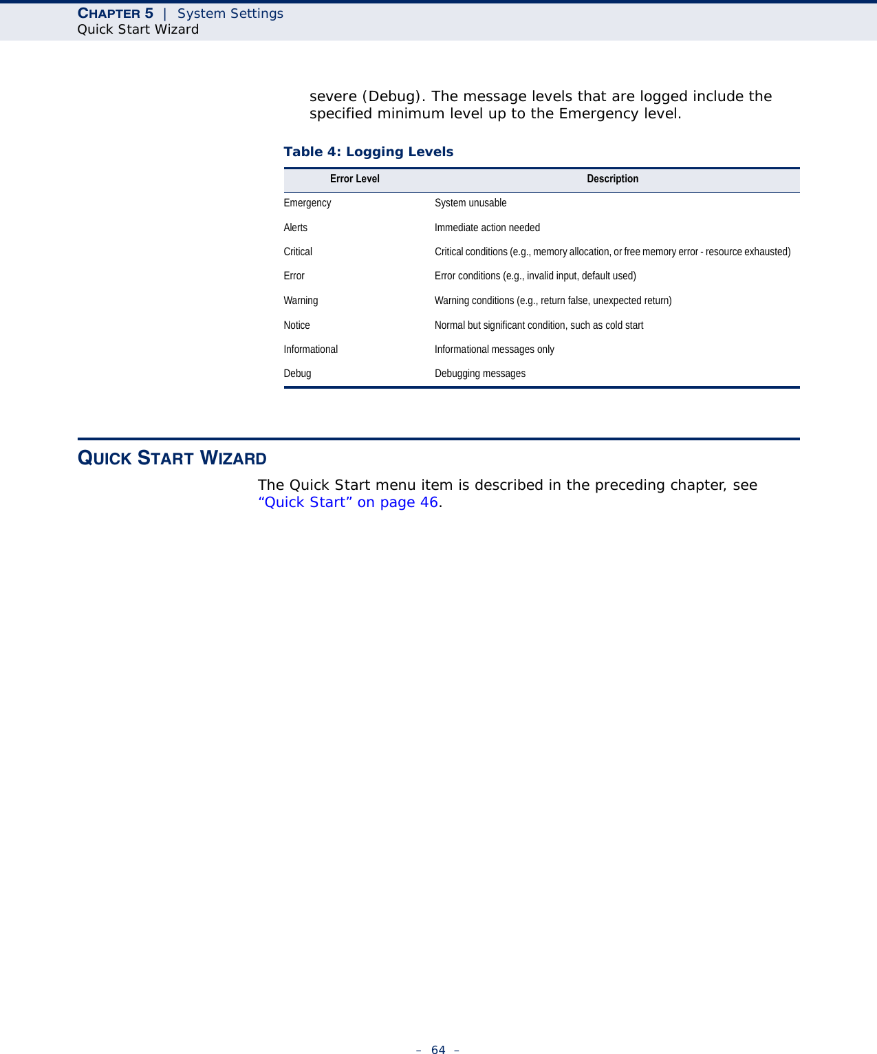
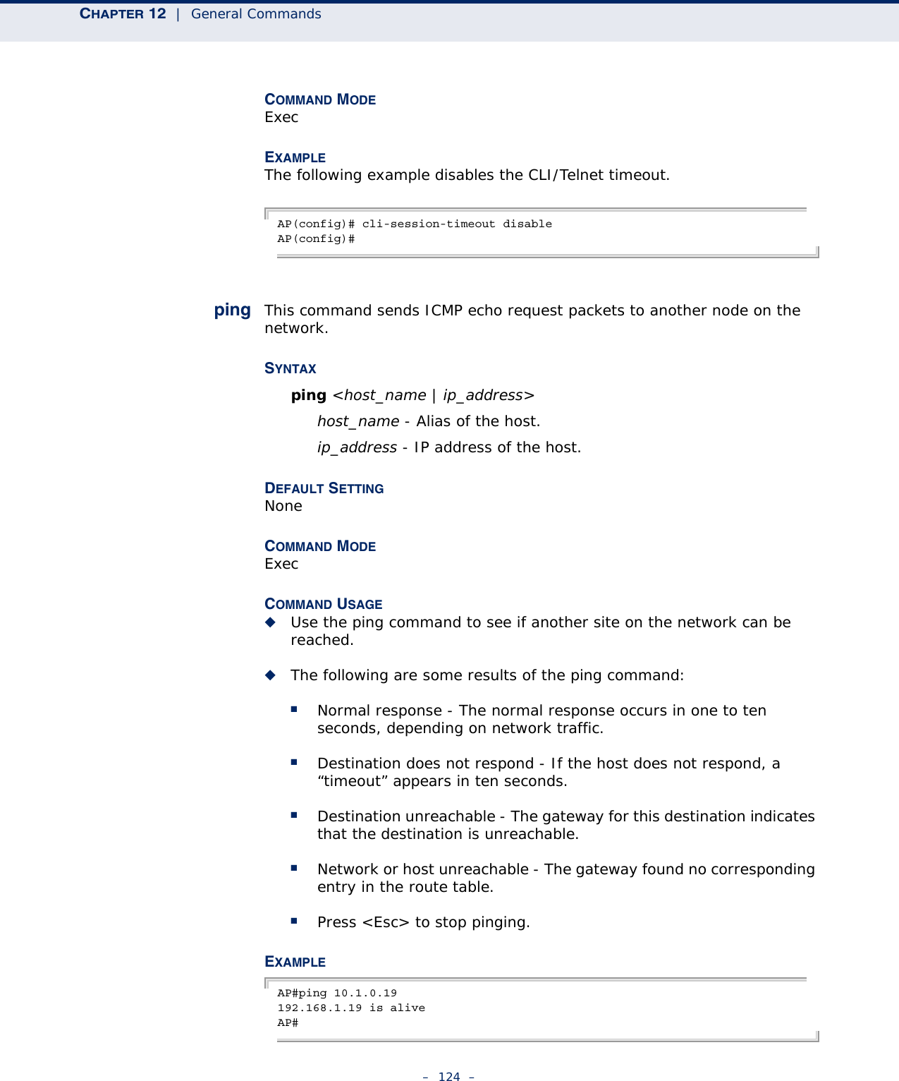
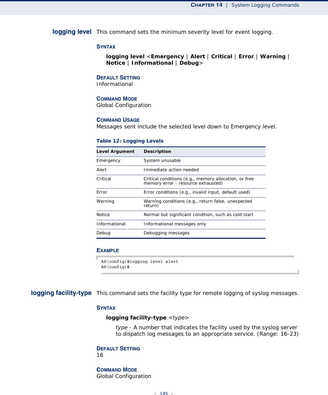
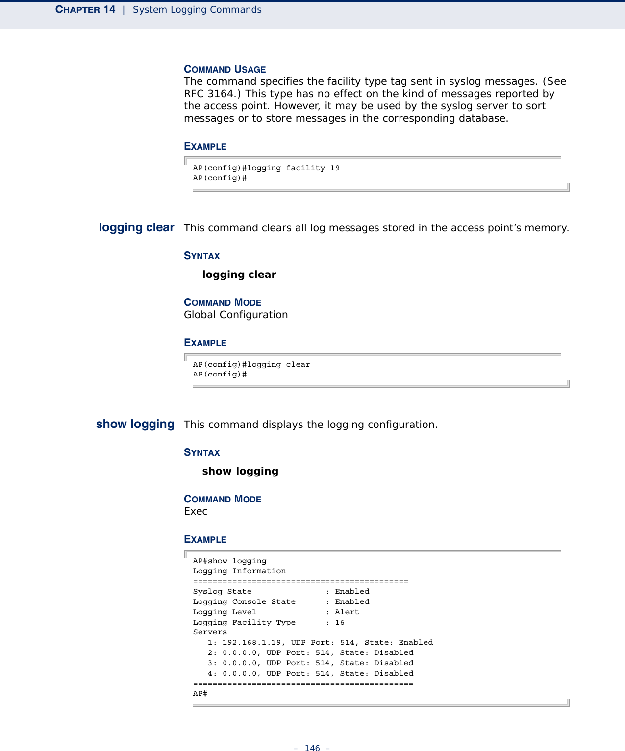
![– 143 –14 SYSTEM LOGGING COMMANDSThese commands are used to configure system logging on the access point.logging on This command controls logging of error messages; i.e., sending debug or error messages to memory. The no form disables the logging process.SYNTAX[no] logging onDEFAULT SETTINGDisabledCOMMAND MODE Global ConfigurationCOMMAND USAGE The logging process controls error messages saved to memory. You can use the logging level command to control the type of error messages that are stored in memory. EXAMPLE AP(config)#logging onAP(config)#Table 11: System Management CommandsCommand Function Mode Pagelogging on Controls logging of error messages GC 143logging host Adds a syslog server host IP address that will receive logging messages GC 144logging console Initiates logging of error messages to the console GC 144logging level Defines the minimum severity level for event logging GC 145logging facility-type Sets the facility type for remote logging of syslog messages GC 145logging clear Clears all log entries in access point memory GC 146show logging Displays the state of logging Exec 146show event-log Displays all log entries in access point memory Exec 147](https://usermanual.wiki/Accton-Technology/E21011/User-Guide-1097647-Page-143.png)
![CHAPTER 14 | System Logging Commands– 144 –logging host This command specifies syslog servers host that will receive logging messages. Use the no form to remove syslog server host.SYNTAXlogging host <1 | 2 | 3 | 4> <host_name | host_ip_address> [udp_port]no logging host <1 | 2 | 3 | 4>1 - First syslog server.2 - Second syslog server.3 - Third syslog server.4 - Fourth syslog server.host_name - The name of a syslog server. (Range: 1-20 characters)host_ip_address - The IP address of a syslog server.udp_port - The UDP port used by the syslog server.DEFAULT SETTING NoneCOMMAND MODE Global ConfigurationEXAMPLE AP(config)#logging host 1 10.1.0.3AP(config)#logging console This command initiates logging of error messages to the console. Use the no form to disable logging to the console.SYNTAXlogging consoleno logging consoleDEFAULT SETTING DisabledCOMMAND MODE Global ConfigurationEXAMPLE AP(config)#logging consoleAP(config)#](https://usermanual.wiki/Accton-Technology/E21011/User-Guide-1097647-Page-144.png)
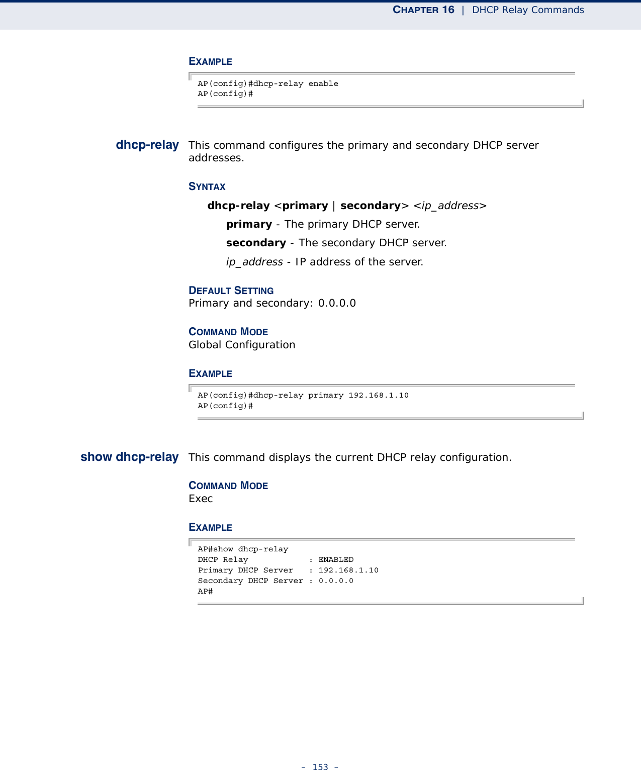
![– 152 –16 DHCP RELAY COMMANDSDynamic Host Configuration Protocol (DHCP) can dynamically allocate an IP address and other configuration information to network clients that broadcast a request. To receive the broadcast request, the DHCP server would normally have to be on the same subnet as the client. However, when the access point’s DHCP relay agent is enabled, received client requests can be forwarded directly by the access point to a known DHCP server on another subnet. Responses from the DHCP server are returned to the access point, which then broadcasts them back to clients.dhcp-relay enable This command enables the access point’s DHCP relay agent. Use the no form to disable the agent.SYNTAX[no] dhcp-relay enableDEFAULT SETTING DisabledCOMMAND MODE Global ConfigurationCOMMAND USAGE ◆For the DHCP relay agent to function, the primary DHCP server must be configured using the dhcp-relay primary command. A secondary DHCP server does not need to be configured, but it is recommended.◆If there is no response from the primary DHCP server, and a secondary server has been configured, the agent will then attempt to send DHCP requests to the secondary server.Table 14: DHCP Relay CommandsCommand Function Mode Pagedhcp-relay enable Enables the DHCP relay agent GC 152dhcp-relay Sets the primary and secondary DHCP server address GC 153show dhcp-relay Shows current DHCP relay configuration settings Exec 153](https://usermanual.wiki/Accton-Technology/E21011/User-Guide-1097647-Page-152.png)
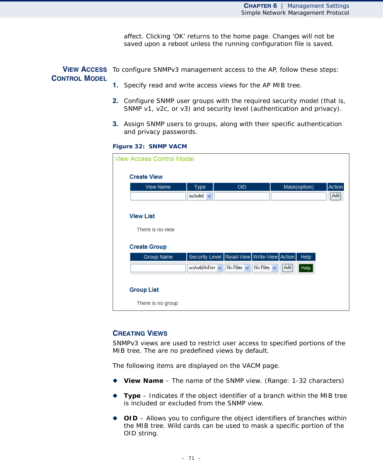
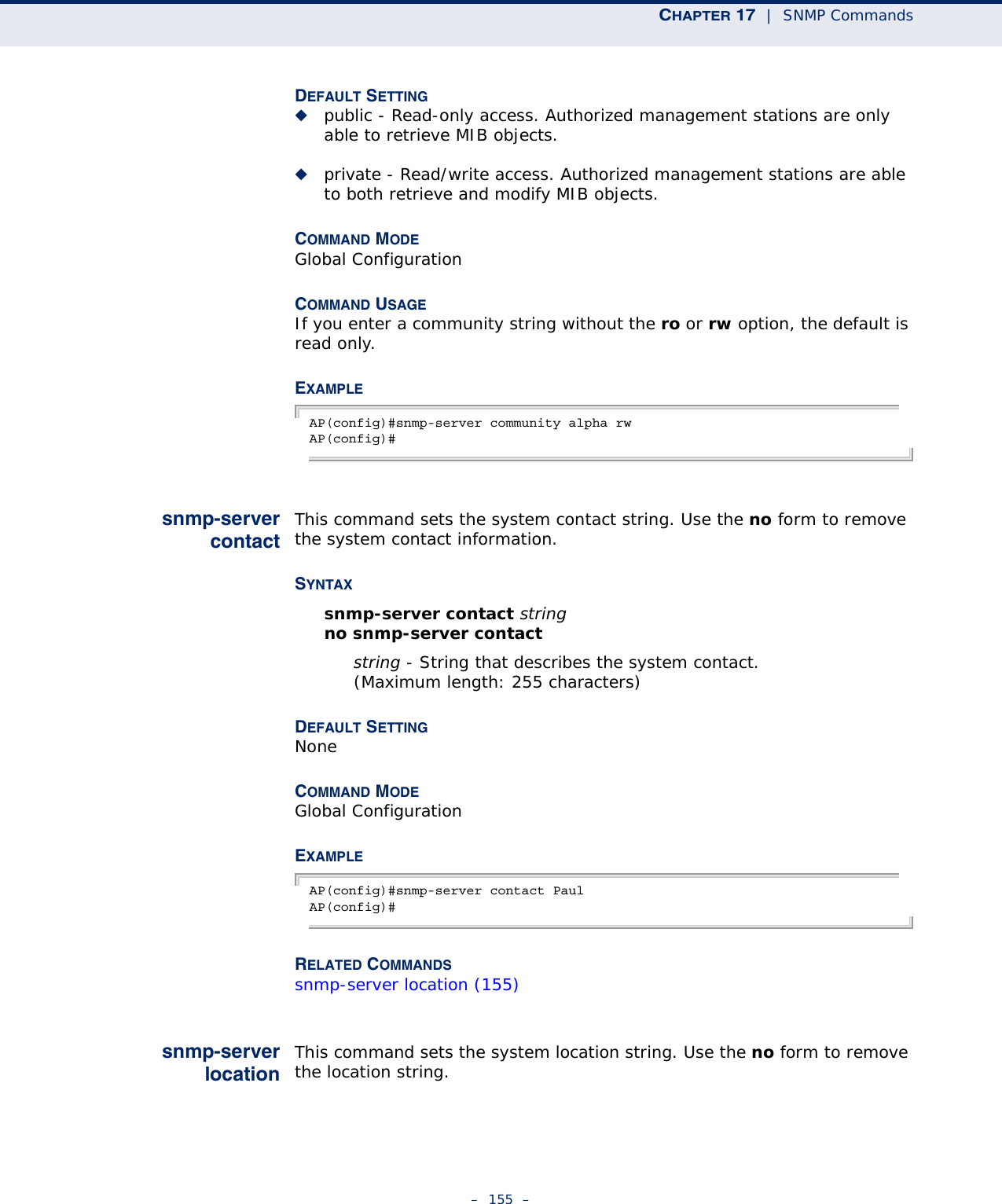
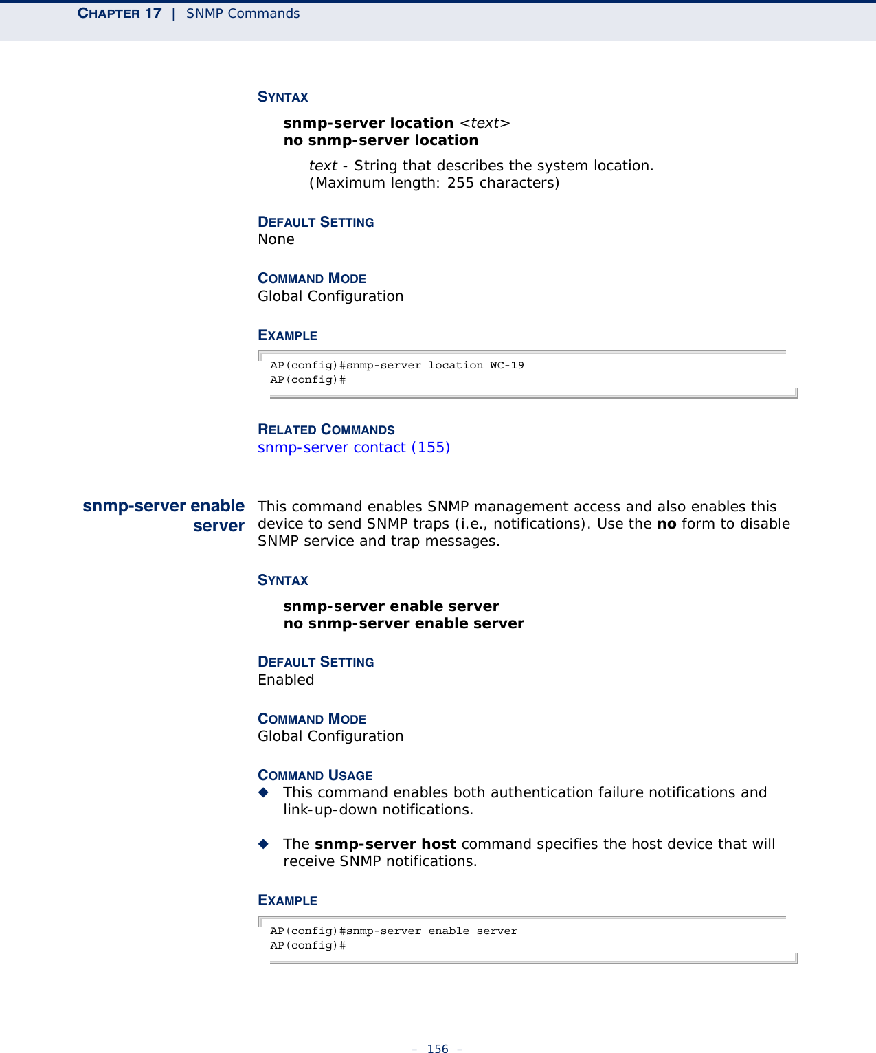
![– 154 –17 SNMP COMMANDSControls access to this access point from management stations using the Simple Network Management Protocol (SNMP), as well as the hosts that will receive trap messages.snmp-servercommunityThis command defines the community access string for the Simple Network Management Protocol. Use the no form to remove the specified community string.SYNTAXsnmp-server community string [ro | rw]no snmp-server community stringstring - Community string that acts like a password and permits access to the SNMP protocol. (Maximum length: 23 characters, case sensitive)ro - Specifies read-only access. Authorized management stations are only able to retrieve MIB objects. rw - Specifies read/write access. Authorized management stations are able to both retrieve and modify MIB objects.Table 15: SNMP CommandsCommand Function Mode Pagesnmp-server community Sets up the community access string to permit access to SNMP commands GC 154snmp-server contact Sets the system contact string GC 155snmp-server location Sets the system location string GC 155snmp-server enable server Enables SNMP service and traps GC 156snmp-server host Specifies the recipient of an SNMP notification operation GC 157snmp-server trap Enables specific SNMP notifications GC 157snmp-server user Sets the name of the SNMP v3 user GC 161snmp-server targets Configures SNMP v3 notification targets GC 162snmp-server filter Configures SNMP v3 notification filters GC 163show snmp users Displays SNMP v3 user settings Exec 164show snmp target Displays the SNMP v3 notification targets Exec 164show snmp filter Displays the SNMP v3 notification filters Exec 165show snmp Displays the status of SNMP communications Exec 165](https://usermanual.wiki/Accton-Technology/E21011/User-Guide-1097647-Page-154.png)
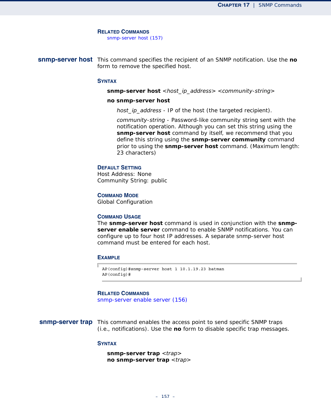
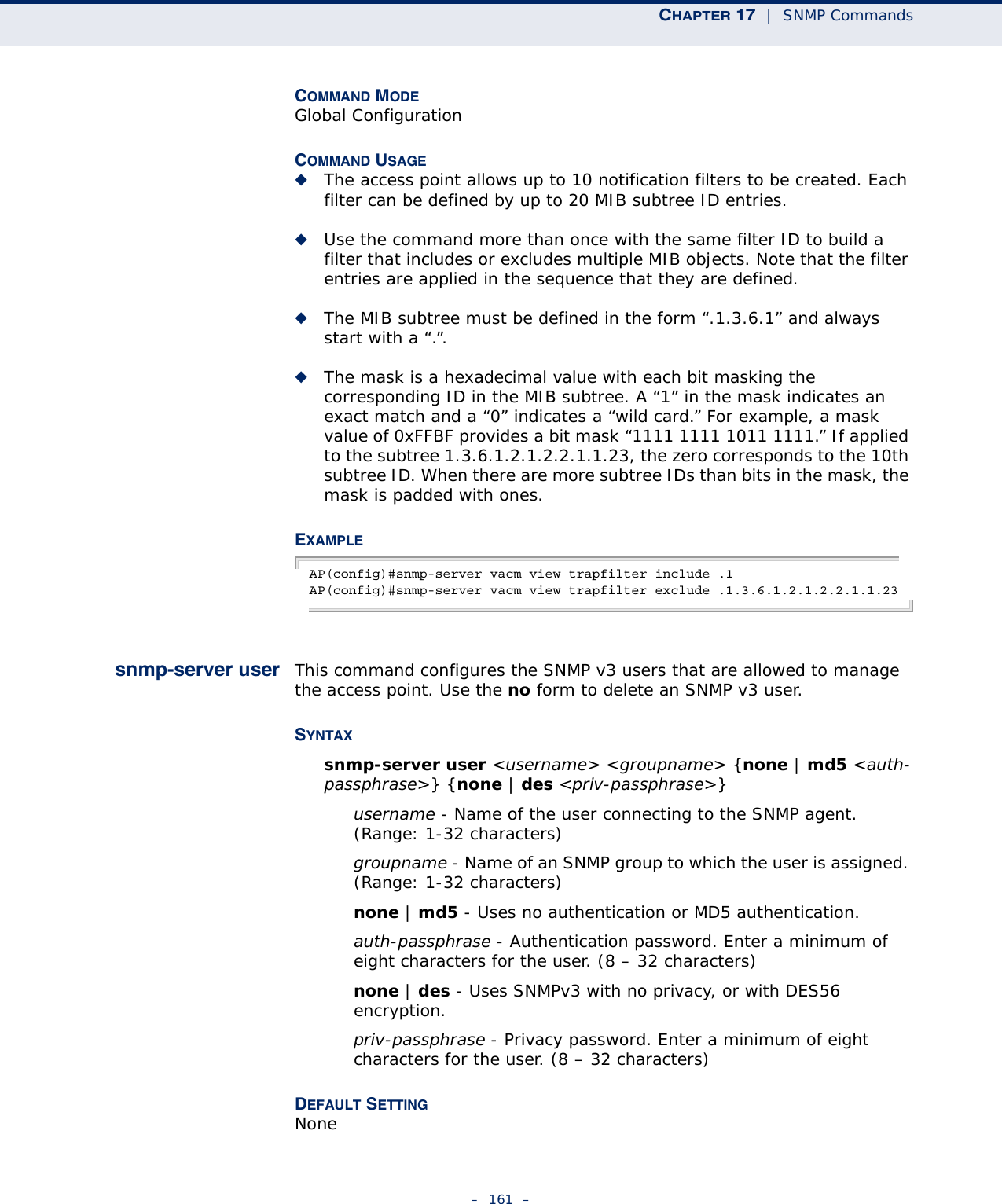
![CHAPTER 17 | SNMP Commands– 159 –sysSystemDown - The access point is about to shutdown and reboot.sysSystemUp - The access point is up and running.DEFAULT SETTING All traps enabledCOMMAND MODE Global ConfigurationCOMMAND USAGE This command is used in conjunction with the snmp-server host and snmp-server enable server commands to enable SNMP notifications.EXAMPLE AP(config)#no snmp-server trap dot11StationAssociationAP(config)#snmp-server vacmviewThis command configures SNMP v3 vacm views. Use the no form to delete an SNMP v3 view or remove a subtree from a filter.SYNTAXsnmp-server vacm view <name> [included | excluded] <subtree> [mask <mask>]name - A user-defined name that identifies an SNMP v3 view. (Maximum length: 32 characters)include - Defines a filter type that includes objects in the MIB subtree.exclude - Defines a filter type that excludes objects in the MIB subtree.subtree - The part of the MIB subtree that is to be filtered.mask - An optional hexadecimal value bit mask to define objects in the MIB subtree.DEFAULT SETTING NoneCOMMAND MODE Global ConfigurationCOMMAND USAGE ◆The access point allows up to 10 notification filters to be created. Each filter can be defined by up to 20 MIB subtree ID entries.](https://usermanual.wiki/Accton-Technology/E21011/User-Guide-1097647-Page-159.png)
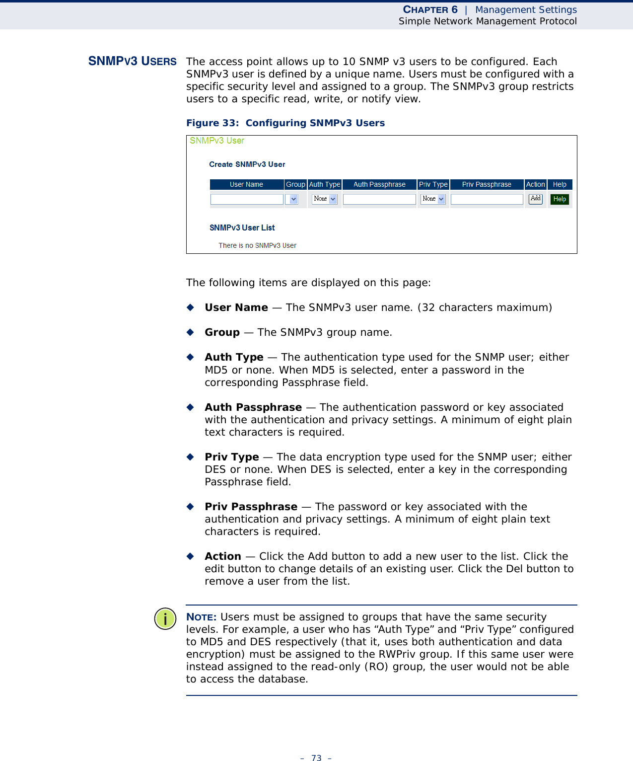
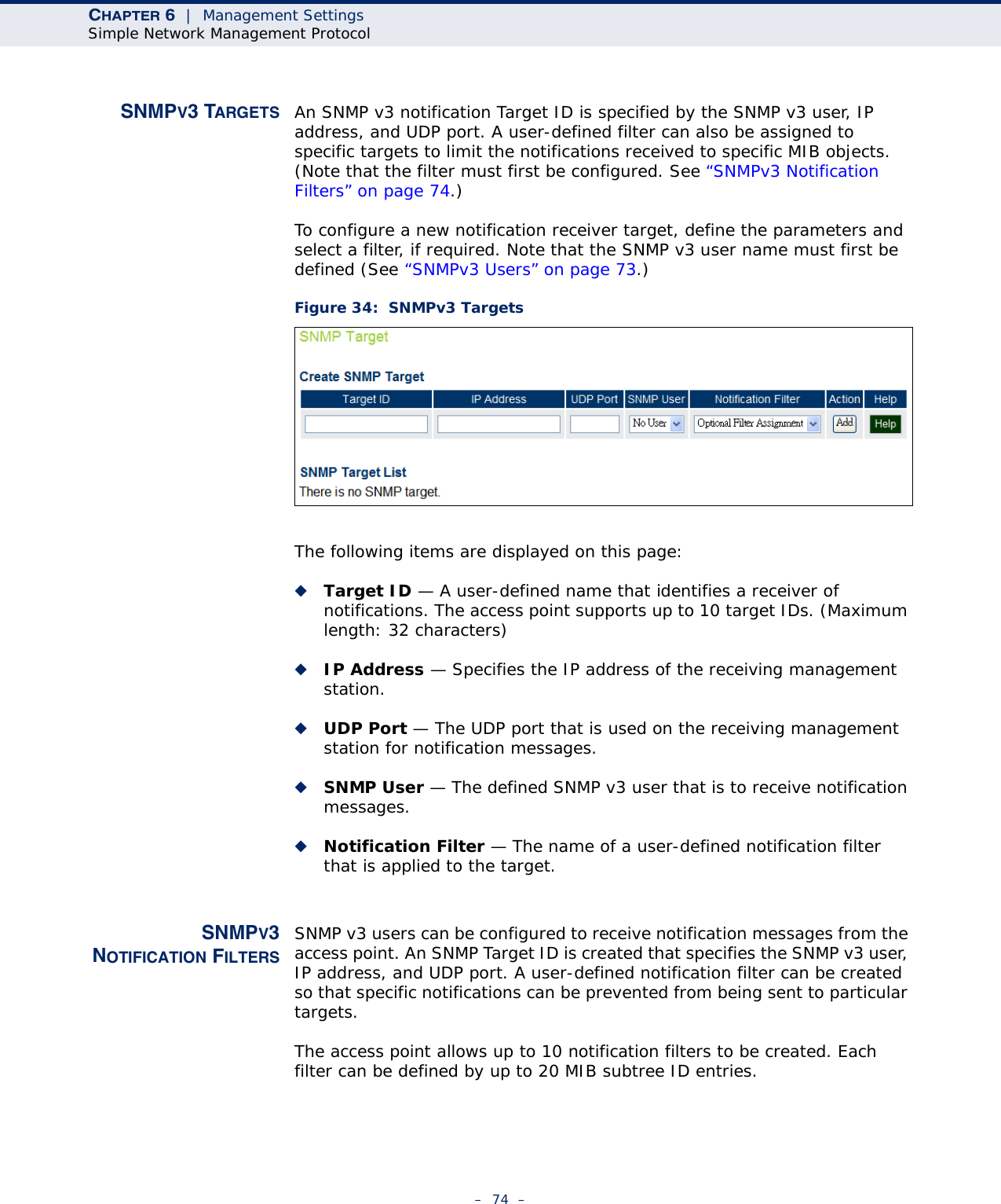
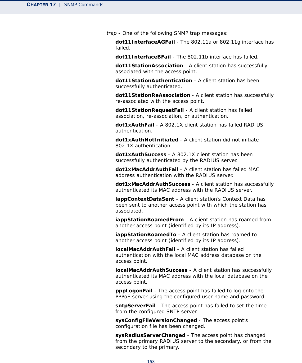
![CHAPTER 17 | SNMP Commands– 162 –COMMAND MODE Global ConfigurationCOMMAND USAGE ◆Up to 10 SNMPv3 users can be configured on the access point.◆The SNMP engine ID is used to compute the authentication/privacy digests from the pass phrase. You should therefore configure the engine ID with the snmp-server engine-id command before using this configuration command.◆Users must be assigned to groups that have the same security levels. If a user who has “AuthPriv” security (uses authentication and encryption) is assigned to a NoAuthNoPriv, the user will not be able to access the database. An AuthPriv user must be assigned to the group with the AuthPriv security level.EXAMPLE AP(config)#snmp-server user User Name<1-32> :chrisGroup Name<1-32> :RWPrivAuthtype(md5,<cr>none):md5Passphrase<8-32>:a good secretPrivacy(des,<cr>none) :desPassphrase<8-32>:a very good secretAP(config)#snmp-server targets This command configures SNMP v3 notification targets. Use the no form to delete an SNMP v3 target.SYNTAXsnmp-server targets <target-id> <ip-addr> <sec-name> udp-port <port-number> [notification-filter-id]no snmp-server targets <target-id>target-id - A user-defined name that identifies a receiver of SNMP notifications. (Maximum length: 32 characters)ip-addr - Specifies the IP address of the management station to receive notifications.sec-name - The defined SNMP v3 user name that is to receive notifications.udp-port - The UDP port that is used on the receiving management station for notifications.notification-filter-id - The name if a defined notification filter.DEFAULT SETTING None](https://usermanual.wiki/Accton-Technology/E21011/User-Guide-1097647-Page-162.png)
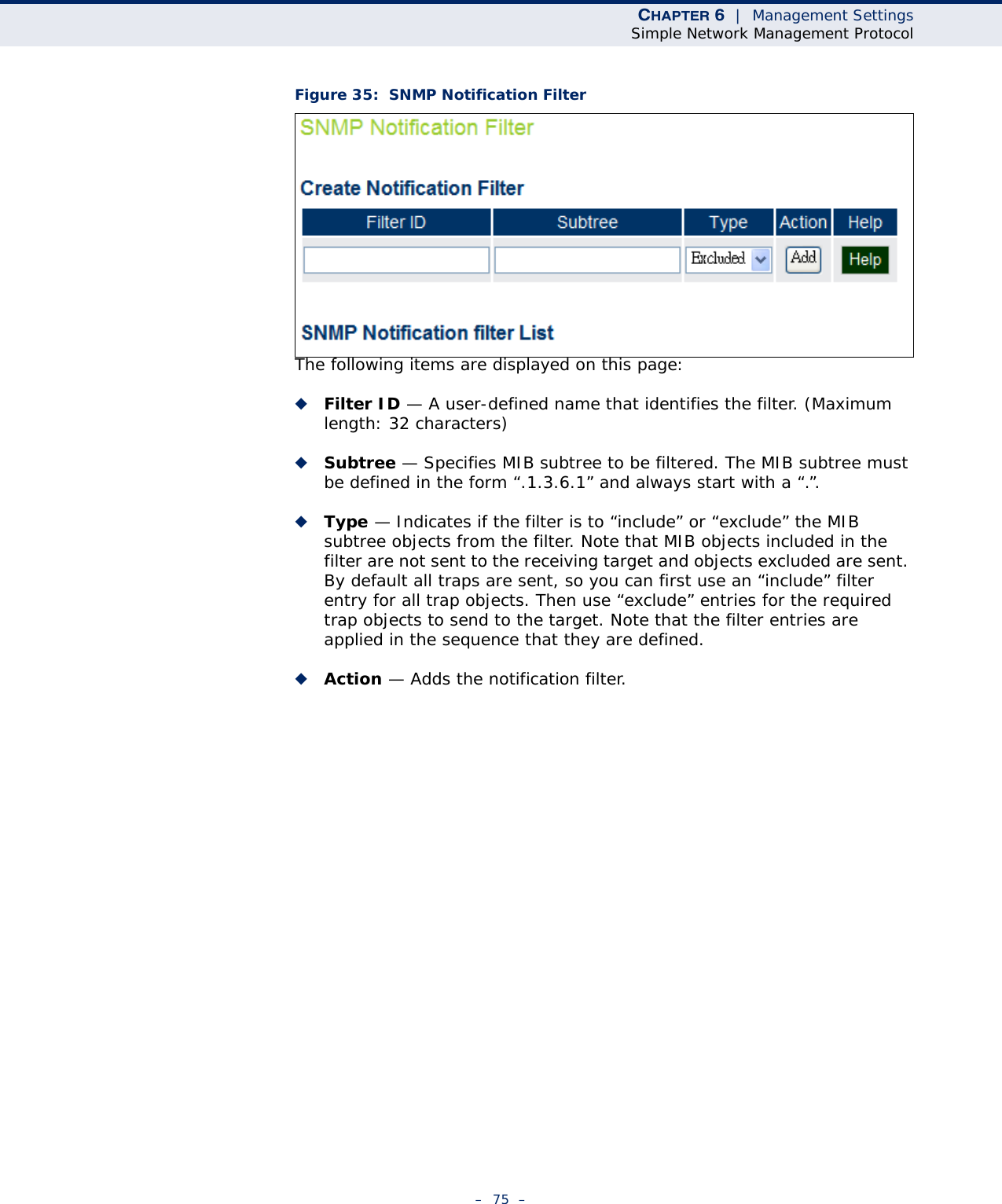
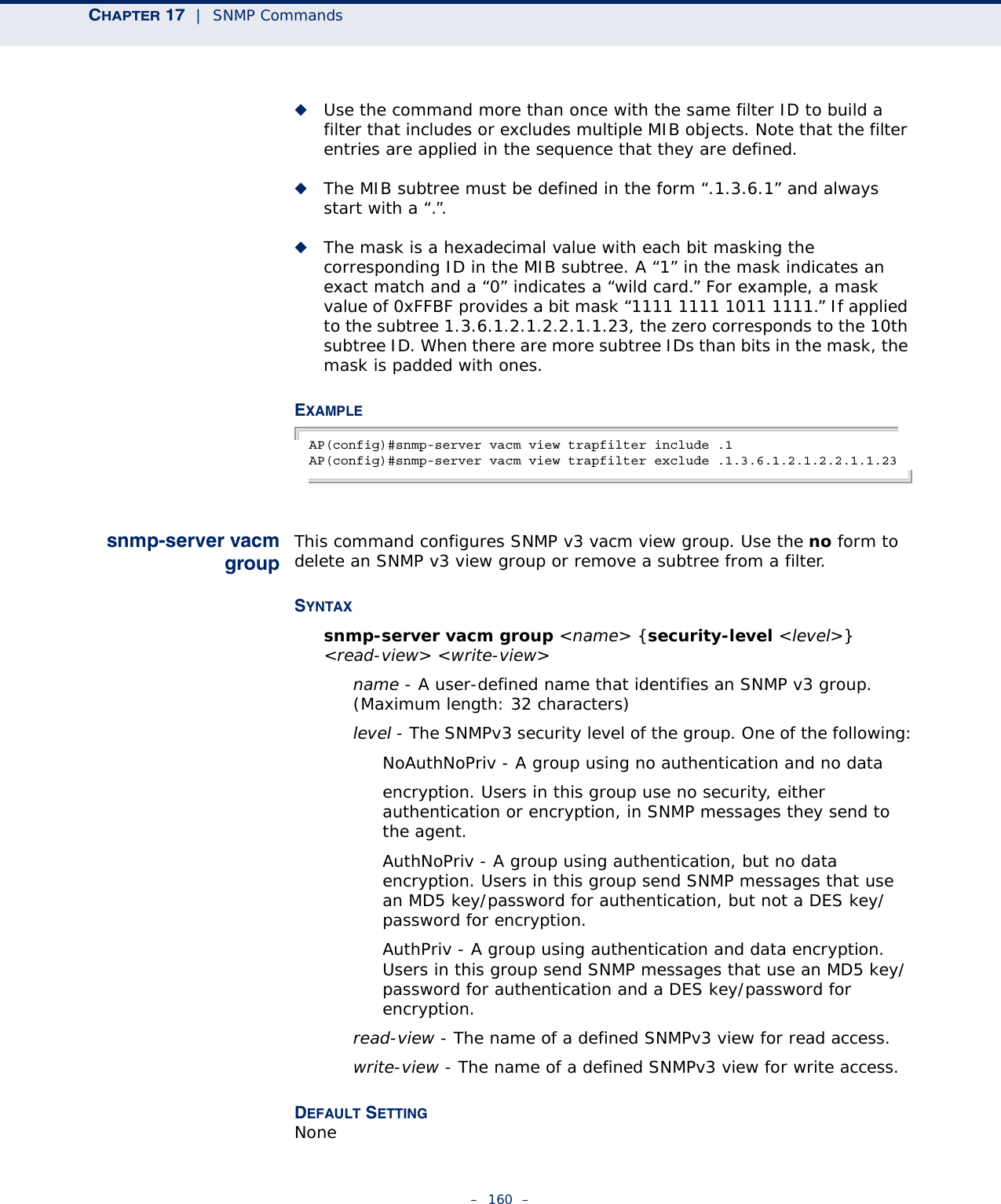
![CHAPTER 17 | SNMP Commands– 163 –COMMAND MODE Global ConfigurationCOMMAND USAGE ◆The access point supports up to 10 SNMP v3 target IDs.◆The SNMP v3 user name that is specified in the target must first be configured using the snmp-server user command.EXAMPLE AP(config)#snmp-server targets mytraps 192.168.1.33 chrisAP(config)#snmp-server filter This command configures SNMP v3 notification filters. Use the no form to delete an SNMP v3 filter or remove a subtree from a filter.SYNTAXsnmp-server filter <filter-id> <include | exclude> <subtree> no snmp-server filter <filter-id> [subtree]filter-id - A user-defined name that identifies an SNMP v3 notification filter. (Maximum length: 32 characters)include - Defines a filter type that includes objects in the MIB subtree.exclude - Defines a filter type that excludes objects in the MIB subtree.subtree - The part of the MIB subtree that is to be filtered.DEFAULT SETTING NoneCOMMAND MODE Global ConfigurationCOMMAND USAGE ◆The access point allows up to 10 notification filters to be created. Each filter can be defined by up to 20 MIB subtree ID entries.◆Use the command more than once with the same filter ID to build a filter that includes or excludes multiple MIB objects. Note that the filter entries are applied in the sequence that they are defined.◆The MIB subtree must be defined in the form “.1.3.6.1” and always start with a “.”.](https://usermanual.wiki/Accton-Technology/E21011/User-Guide-1097647-Page-163.png)
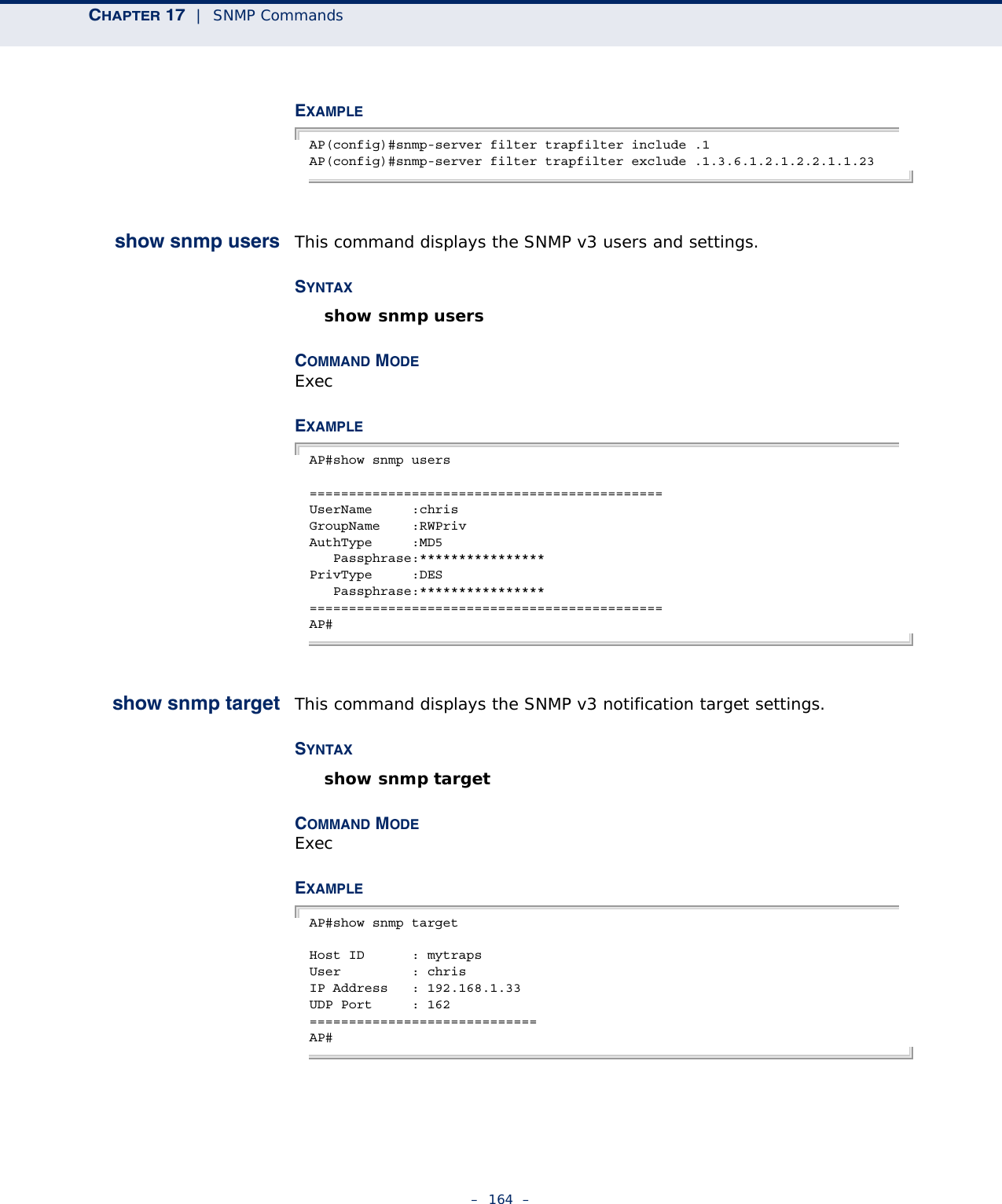
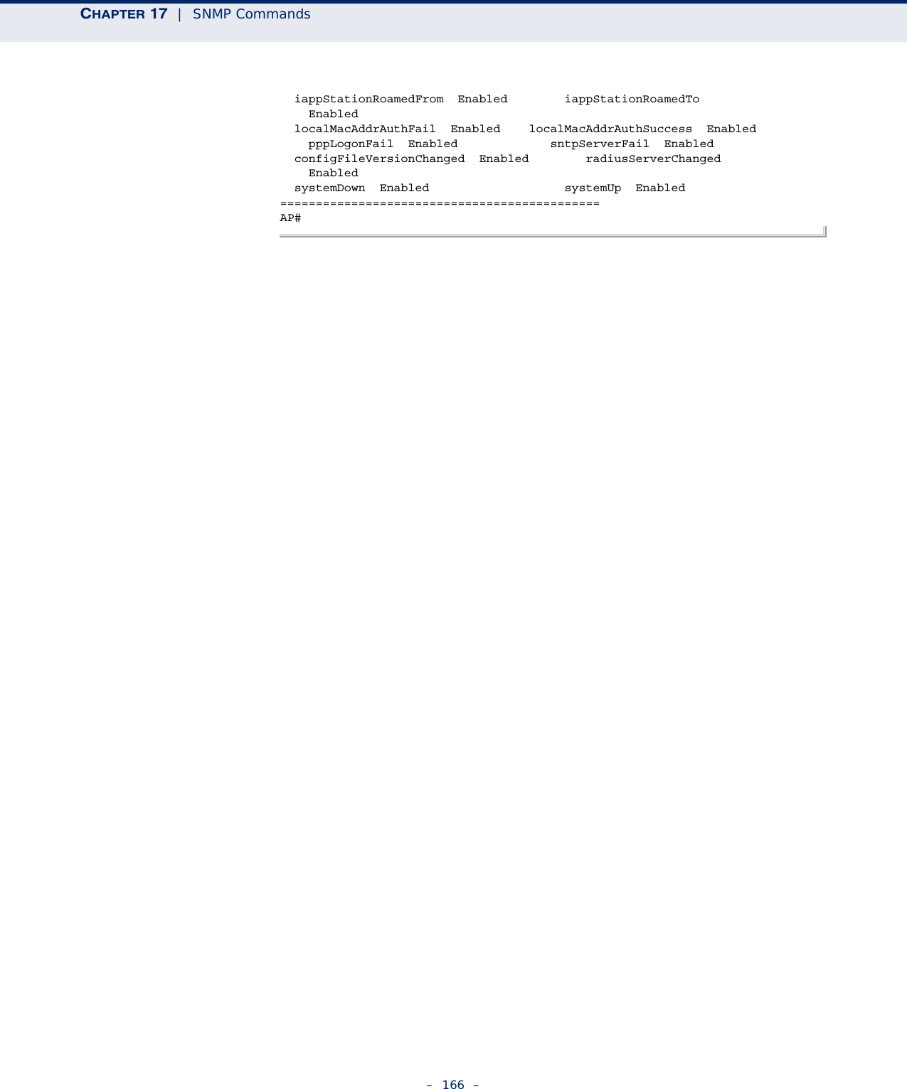
![CHAPTER 17 | SNMP Commands– 165 –show snmp vacmgroup / show snmpvacm viewThis command displays the SNMP v3 notification filter settings.SYNTAXshow snmp filter [filter-id] filter-id - A user-defined name that identifies an SNMP v3 notification filter. (Maximum length: 32 characters)COMMAND MODE ExecEXAMPLE AP#show snmp filterFilter: trapfilter Type: include Subtree: iso.3.6.1.2.1.2.2.1 Type: exclude Subtree: iso.3.6.1.2.1.2.2.1.1.23=============================AP#show snmpThis command displays the SNMP configuration settings.COMMAND MODE ExecEXAMPLEAP#show snmpSNMP Information==============================================Service State : EnableCommunity (ro) : *****Community (rw) : *****Location : WC-19Contact : PaulEngineId :80:00:07:e5:80:00:00:2e:62:00:00:00:18EngineBoots:1Trap Destinations: 1: 192.168.1.9, Community: *****, State: Enabled 2: 0.0.0.0, Community: *****, State: Disabled 3: 0.0.0.0, Community: *****, State: Disabled 4: 0.0.0.0, Community: *****, State: Disabled dot11InterfaceAGFail Enabled dot11InterfaceBFail Enabled dot11StationAssociation Enabled dot11StationAuthentication Enabled dot11StationReAssociation Enabled dot11StationRequestFail Enabled dot1xAuthFail Enabled dot1xAuthNotInitiated Enabled dot1xAuthSuccess Enabled dot1xMacAddrAuthFail Enabled dot1xMacAddrAuthSuccess Enabled iappContextDataSent Enabled](https://usermanual.wiki/Accton-Technology/E21011/User-Guide-1097647-Page-165.png)
![– 167 –18 FLASH/FILE COMMANDSThese commands are used to manage the system code or configuration files.dual-image This command specifies the image used to start up the system.SYNTAXdual-image boot image [a | b]a/b - Specifies the image file to be used as a primary startup file.DEFAULT SETTING NoneCOMMAND MODE ExecCOMMAND USAGE ◆Specifies the name of the code file on the server. The new firmware file name should not contain slashes (\ or /), the leading letter of the file name should not be a period (.), and the maximum length for file names is 32 characters for files on the access point. (Valid characters: A-Z, a-z, 0-9, “.”, “-”, “_”)◆If the file contains an error, it cannot be set as the default file. EXAMPLEAP# dual-image boot-image AChange image to AAP#Table 16: Flash/File CommandsCommand Function Mode Pagedual-image Specifies the file or image used to start up the system GC 167copy Copies a code image or configuration between flash memory and a FTP/TFTP server Exec 168show dual-image Displays the name of the current operation code file thatbooted the systemExec 169](https://usermanual.wiki/Accton-Technology/E21011/User-Guide-1097647-Page-167.png)
![CHAPTER 18 | Flash/File Commands– 168 –copy This command copies a boot file, code image, or configuration file between the access point’s flash memory and a FTP/TFTP server. When you save the configuration settings to a file on a FTP/TFTP server, that file can later be downloaded to the access point to restore system operation. The success of the file transfer depends on the accessibility of the FTP/TFTP server and the quality of the network connection. SYNTAXcopy {ftp [firmware | config] <file-name> <ip-address> <user-name> <password> | tftp [firmware | config] <file-name> <ip-address>} copy config {ftp <file-name> <ip-address> <user-name> <password> | tftp <file-name> <ip-address>} copy running startupftp - Keyword that allows you to copy to/from an FTP server.tftp - Keyword that allows you to copy to/from a TFTP server.file - Keyword that allows you to copy to/from a flash memory file. config - Keyword that allows you to upload the configuration file from flash memory. DEFAULT SETTING NoneCOMMAND MODE ExecCOMMAND USAGE ◆The system prompts for data required to complete the copy command. ◆Only a configuration file can be uploaded to an FTP/TFTP server, but every type of file can be downloaded to the access point.◆The destination file name should not contain slashes (\ or /), the leading letter of the file name should not be a period (.), and the maximum length for file names on the FTP/TFTP server is 255 characters or 32 characters for files on the access point. (Valid characters: A-Z, a-z, 0-9, “.”, “-”, “_”)◆Due to the size limit of the flash memory, the access point supports only two operation code files.◆The system configuration file must be named “syscfg” in all copy commands.EXAMPLE The following example shows how to upload the configuration settings to a file on the TFTP server:](https://usermanual.wiki/Accton-Technology/E21011/User-Guide-1097647-Page-168.png)
![CHAPTER 18 | Flash/File Commands– 169 –AP#copy config tftpTFTP Source file name:syscfgTFTP Server IP:192.168.1.19AP#The following example shows how to download a configuration file: AP#copy tftp file1. Application image2. Config file3. Boot block imageSelect the type of download<1,2,3>: [1]:2TFTP Source file name:syscfgTFTP Server IP:192.168.1.19AP#show dual-image This command displays the name of the current operation code file that booted the system and the file saved as a secondary image.SYNTAXshow snmp filter-assignmentsCOMMAND MODE ExecEXAMPLE AP#show dual-image Image Status Version----------------------------------------------- Image A (Active) 1.1.0.6 Image B (Backup) 1.1.0.1AP#](https://usermanual.wiki/Accton-Technology/E21011/User-Guide-1097647-Page-169.png)
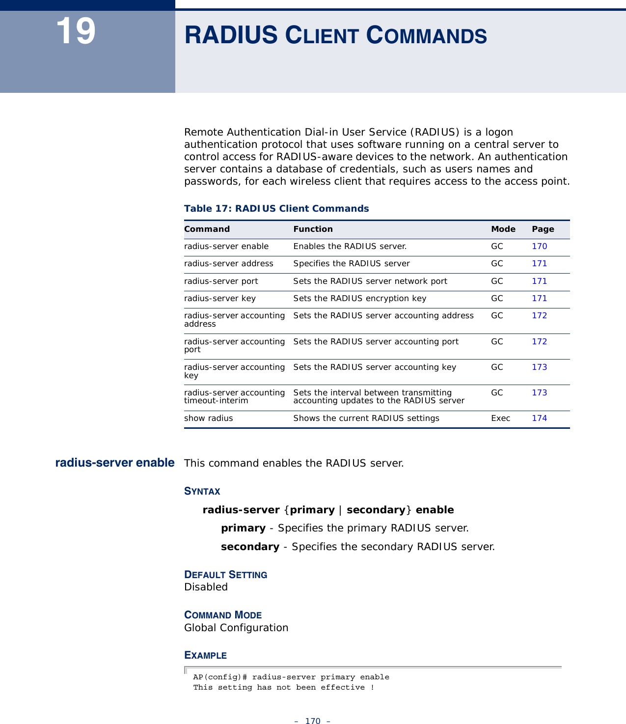
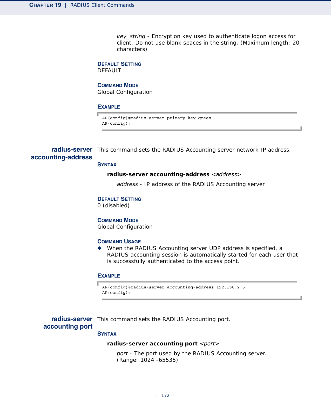
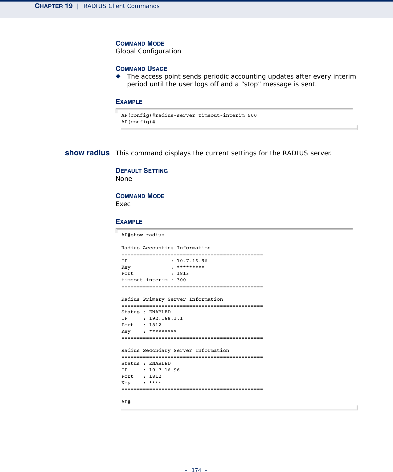
![CHAPTER 19 | RADIUS Client Commands– 171 –If want to take effect, please execute make-radius-effective command !AP(config)#radius-serveraddressThis command specifies the primary and secondary RADIUS server address. SYNTAXradius-server {primary | secondary} address <address>address - IP address of server.DEFAULT SETTING NoneCOMMAND MODE Global ConfigurationEXAMPLE AP(config)#radius-server address 192.168.1.25AP(config)#radius-server port This command sets the RADIUS server network port. SYNTAXradius-server {primary | secondary} port <port_number>port_number - RADIUS server UDP port used for authentication messages. (Range: 1024-65535)DEFAULT SETTING 1812COMMAND MODE Global ConfigurationEXAMPLE AP(config)#radius-server secondary port 181AP(config)#radius-server key This command sets the RADIUS encryption key. SYNTAX radius-server {primary | secondary] key <key_string>](https://usermanual.wiki/Accton-Technology/E21011/User-Guide-1097647-Page-171.png)
![CHAPTER 19 | RADIUS Client Commands– 173 –DEFAULT SETTING 0 (disabled)COMMAND MODE Global ConfigurationCOMMAND USAGE ◆When the RADIUS Accounting server UDP port is specified, a RADIUS accounting session is automatically started for each user that is successfully authenticated to the access point.EXAMPLE AP(config)#radius-server accounting port 1024AP(config)#radius-serveraccounting keyThis command sets the RADIUS Accounting key. SYNTAXradius-server accounting key <key>key - The RADIUS Accounting server keyphrase. DEFAULT SETTING 0 (disabled)COMMAND MODE Global ConfigurationEXAMPLE AP(config)#radius-server accounting key greenAP(config)#radius-serveraccountingtimeout-interimThis command sets the interval between transmitting accounting updates to the RADIUS server.SYNTAX radius-server {[primary | secondary] timeout-interim <number_of_seconds>}number_of_seconds - Number of seconds the access point waits between transmitting accounting updates. (Range: 60-86400)DEFAULT SETTING 3600](https://usermanual.wiki/Accton-Technology/E21011/User-Guide-1097647-Page-173.png)
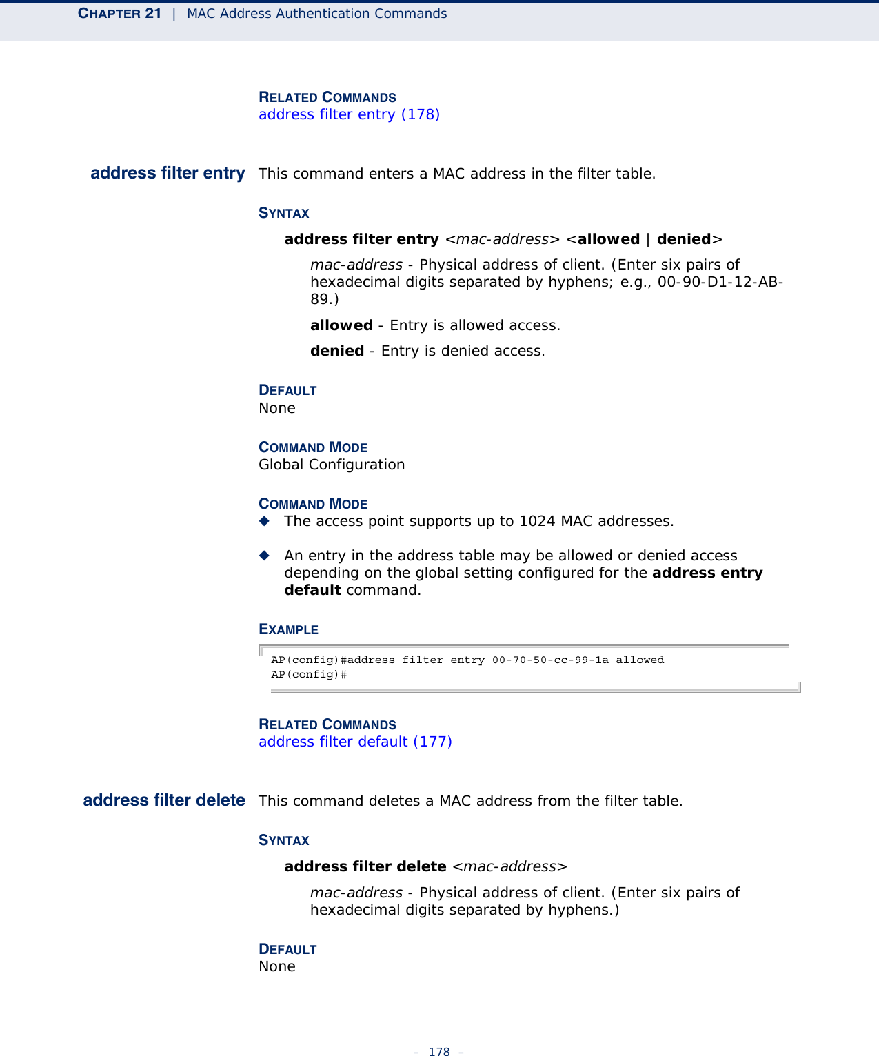
![CHAPTER 21 | MAC Address Authentication Commands– 179 –COMMAND MODEGlobal ConfigurationEXAMPLEAP(config)#address filter delete 00-70-50-cc-99-1b AP(config)#mac-authenticationserverThis command sets address filtering to be performed with local or remote options. Use the no form to disable MAC address authentication.SYNTAXmac-authentication server [local | remote]local - Authenticate the MAC address of wireless clients with the local authentication database during 802.11 association.remote - Authenticate the MAC address of wireless clients with the RADIUS server during 802.1X authentication.DEFAULTDisabledCOMMAND MODEGlobal ConfigurationEXAMPLEAP(config)#mac-authentication server remoteAP(config)#RELATED COMMANDSaddress filter entry (178)radius-server address (171)mac-authenticationsession-timeoutThis command sets the interval at which associated clients will be re-authenticated with the RADIUS server authentication database. Use the no form to disable reauthentication.SYNTAXmac-authentication session-timeout <minutes>minutes - Re-authentication interval. (Range: 0-1440)DEFAULT0 (disabled)COMMAND MODEGlobal Configuration](https://usermanual.wiki/Accton-Technology/E21011/User-Guide-1097647-Page-179.png)

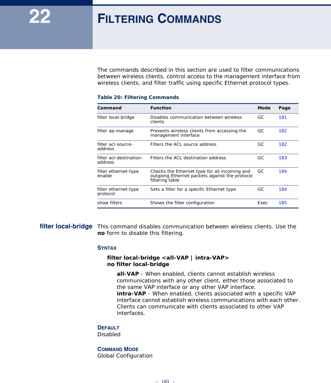
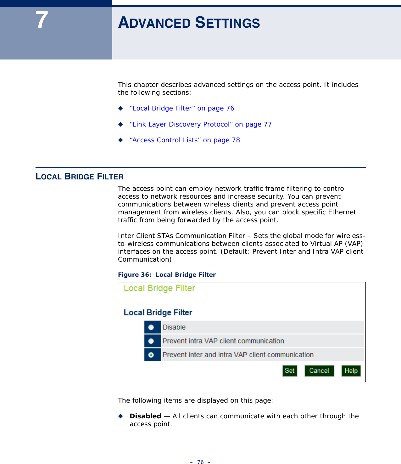
![CHAPTER 22 | Filtering Commands– 182 –COMMAND USAGEThis command can disable wireless-to-wireless communications between clients via the access point. However, it does not affect communications between wireless clients and the wired network.EXAMPLEAP(config)#filter local-bridgeAP(config)#filter ap-manage This command prevents wireless clients from accessing the management interface on the access point. Use the no form to disable this filtering.SYNTAXfilter ap-manageno filter ap-manageDEFAULTEnabledCOMMAND MODEGlobal ConfigurationEXAMPLEAP(config)#filter AP-manageAP(config)#filter acl-destination-address {add | delete} <mac-address>filter acl-source-address enableThis command enables filtering ACL source addresses from the Ethernet port.SYNTAX[no] filter acl-source-address {enable | disable}DEFAULTDisabledCOMMAND MODEGlobal ConfigurationEXAMPLEAP(config)#filter acl-source-address enableAP(config)#](https://usermanual.wiki/Accton-Technology/E21011/User-Guide-1097647-Page-182.png)
![CHAPTER 22 | Filtering Commands– 183 –filter acl-source-address mac-addressThis command enables filtering of source MAC addresses from the Ethernet port.SYNTAX[no] filter acl-source-address {add | delete} addressMAC address - Specifies a MAC address in the form xx-xx-xx-xx-xx-xx. A maximum of eight addresses can be added to the filtering table.DEFAULTDisabledCOMMAND MODEGlobal ConfigurationEXAMPLEAP(config)#filter acl-source-address add xx:xx:xx:xx:xx:xxAP(config)#filter acl-destination-addressenableThis command enables filtering ACL destination addresses from the Ethernet port.SYNTAX[no] filter acl-source-address {enable | disable}DEFAULTDisabledCOMMAND MODEGlobal ConfigurationEXAMPLEAP(config)#filter acl-destination-address enableAP(config)#filter acl-destination-addressmac-addressThis command enables filtering of destination MAC addresses from the Ethernet port.SYNTAX[no] filter acl-destination-address {add | delete} addressMAC address - Specifies a MAC address in the form xx-xx-xx-xx-xx-xx. A maximum of eight addresses can be added to the filtering table.](https://usermanual.wiki/Accton-Technology/E21011/User-Guide-1097647-Page-183.png)
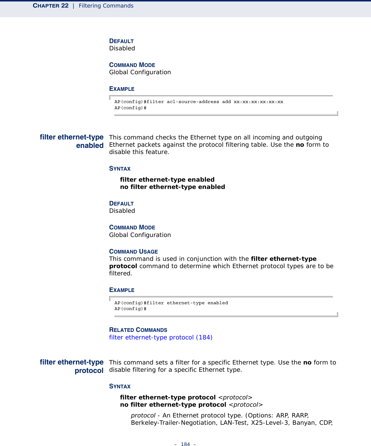
![CHAPTER 22 | Filtering Commands– 185 –DEC XNS, DEC-MOP-Dump-Load, DEC-MOP, DEC-LAT, Ethertalk, Appletalk-ARP, Novell-IPX(old), Novell-IPX(new), EAPOL, Telxon-TXP, Aironet-DDP, Enet-Config-Test, IP, IPv6, NetBEUI, PPPoE_Discovery, PPPoE_PPP_Session)DEFAULTNoneCOMMAND MODEGlobal ConfigurationCOMMAND USAGEUse the filter ethernet-type enable command to enable filtering for Ethernet types specified in the filtering table, or the no filter ethernet-type enable command to disable all filtering based on the filtering table.EXAMPLEAP(config)#filter ethernet-type protocol ARPAP(config)#RELATED COMMANDSfilter ethernet-type enabled (184)show filters This command shows the filter options and protocol entries in the filter table. SYNTAXshow filters [acl-source-address | acl-destination-address]COMMAND MODEExecEXAMPLEAP#show filtersProtocol Filter Information=======================================================================Local Bridge :Traffic among all client STAs blockedAP Management :DISABLEDEtherType Filter :DISABLEDEnabled EtherType Filters-----------------------------------------------------------------------=======================================================================AP#](https://usermanual.wiki/Accton-Technology/E21011/User-Guide-1097647-Page-185.png)
![CHAPTER 23 | Spanning Tree Commands– 187 –AP(config)bridge stp serviceAP(config)bridge stp br-confforwarding-delayUse this command to configure the spanning tree bridge forward time globally for the wireless bridge. Use the no form to restore the default.SYNTAX bridge stp br-conf forwarding-delay <seconds>no bridge stp br-conf forwarding-delayseconds - Time in seconds. (Range: 4 - 30 seconds)The minimum value is the higher of 4 or [(max-age / 2) + 1]. DEFAULT SETTING 15 secondsCOMMAND MODE Global ConfigurationCOMMAND USAGE This command sets the maximum time (in seconds) the root device will wait before changing states (i.e., discarding to learning to forwarding). This delay is required because every device must receive information about topology changes before it starts to forward frames. In addition, each port needs time to listen for conflicting information that would make it return to the discarding state; otherwise, temporary data loops might result.EXAMPLEAP(config)#bridge stp br-conf forwarding-delay 20AP(config)# bridge stp br-confhello-timeUse this command to configure the spanning tree bridge hello time globally for the wireless bridge. Use the no form to restore the default.SYNTAX bridge stp br-conf hello-time <time>no bridge stp br-conf hello-timetime - Time in seconds. (Range: 1-10 seconds). The maximum value is the lower of 10 or [(max-age / 2) -1]. DEFAULT SETTING 2 seconds](https://usermanual.wiki/Accton-Technology/E21011/User-Guide-1097647-Page-187.png)
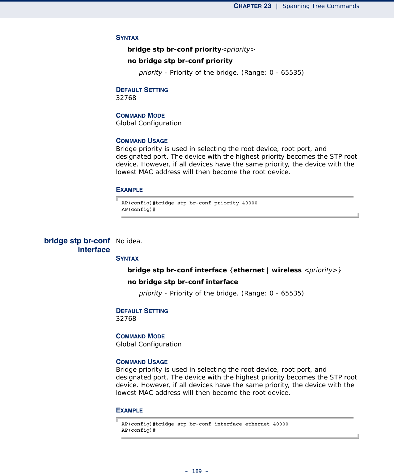
![CHAPTER 23 | Spanning Tree Commands– 188 –COMMAND MODE Global ConfigurationCOMMAND USAGE This command sets the time interval (in seconds) at which the root device transmits a configuration message.EXAMPLE AP(config)#bridge stp br-conf hello-time 5AP(config)#bridge stp br-confmax-ageUse this command to configure the spanning tree bridge maximum age globally for the wireless bridge. Use the no form to restore the default.SYNTAX bridge stp br-conf max-age <seconds>no bridge stp br-conf max-ageseconds - Time in seconds. (Range: 6-40 seconds)The minimum value is the higher of 6 or [2 x (hello-time + 1)].The maximum value is the lower of 40 or [2 x (forward-time - 1)].DEFAULT SETTING 20 secondsCOMMAND MODE Global ConfigurationCOMMAND USAGE This command sets the maximum time (in seconds) a device can wait without receiving a configuration message before attempting to reconfigure. All device ports (except for designated ports) should receive configuration messages at regular intervals. Any port that ages out STP information (provided in the last configuration message) becomes the designated port for the attached LAN. If it is a root port, a new root port is selected from among the device ports attached to the network.EXAMPLE AP(config)#bridge stp max-age 40AP(config)#bridge stp br-confpriorityUse this command to configure the spanning tree priority globally for the wireless bridge. Use the no form to restore the default.](https://usermanual.wiki/Accton-Technology/E21011/User-Guide-1097647-Page-188.png)
![– 193 –24 WDS BRIDGE COMMANDSThe commands described in this section are used to set the operation mode for each access point interface and configure Wireless Distribution System (WDS) forwarding table settings. wds ap This command enables the bridge operation mode for the radio interface.SYNTAXwds apDEFAULT SETTING DisabledCOMMAND MODE Interface Configuration (Wireless) VAPEXAMPLE AP(if-wireless 0 [VAP 0])#wds apAP(if-wireless 0 [VAP 0])#wds sta This command configures WDS STA SSID.SYNTAXwds sta ap <ssid>ssid - Security set identifyer. Maximum: 32 characters.DEFAULT SETTING NoneTable 22: WDS Bridge CommandsCommand Function Mode Pagewds ap Selects the bridge operation mode for a radio interface IC-W VAP 193wds sta Configures the MAC addresses of the parent bridge node IC-W VAP 193show wds wireless Configures MAC addresses of connected child bridge nodes Exec 194](https://usermanual.wiki/Accton-Technology/E21011/User-Guide-1097647-Page-193.png)
![CHAPTER 24 | WDS Bridge Commands– 194 –COMMAND MODE Interface Configuration (Wireless) VAPCOMMAND USAGE Every bridge (except the root bridge) in the wireless bridge network must specify the MAC address of the parent bridge that is linked to the root bridge, or the root bridge itself.EXAMPLE AP(if-wireless 0 [VAP 0])#wds sta ap redAP(if-wireless 0 [VAP 0])#show wds wireless This command displays the current WDS forwarding table aging time setting.COMMAND MODE ExecEXAMPLE AP#show wds wirelessAP#](https://usermanual.wiki/Accton-Technology/E21011/User-Guide-1097647-Page-194.png)
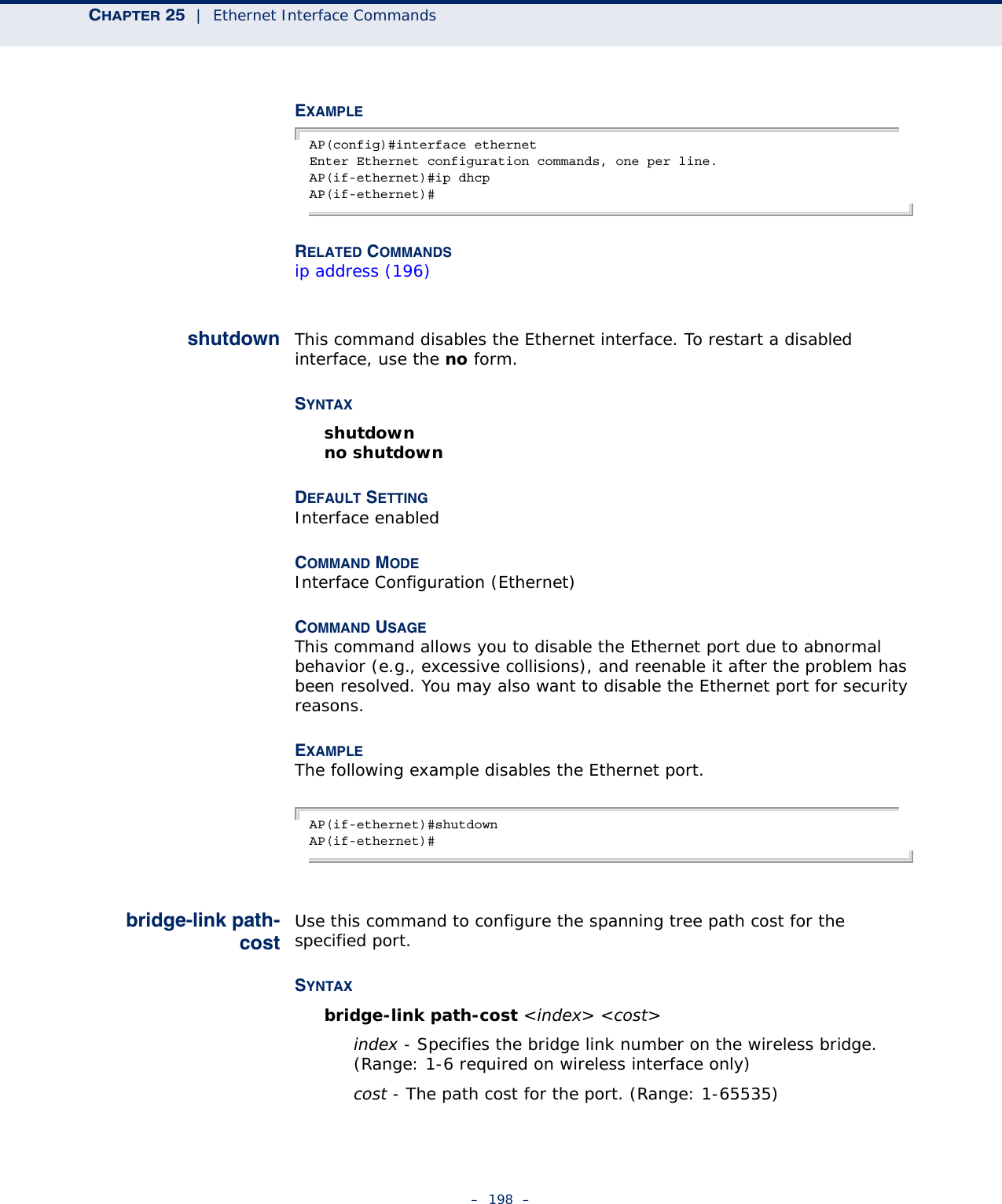
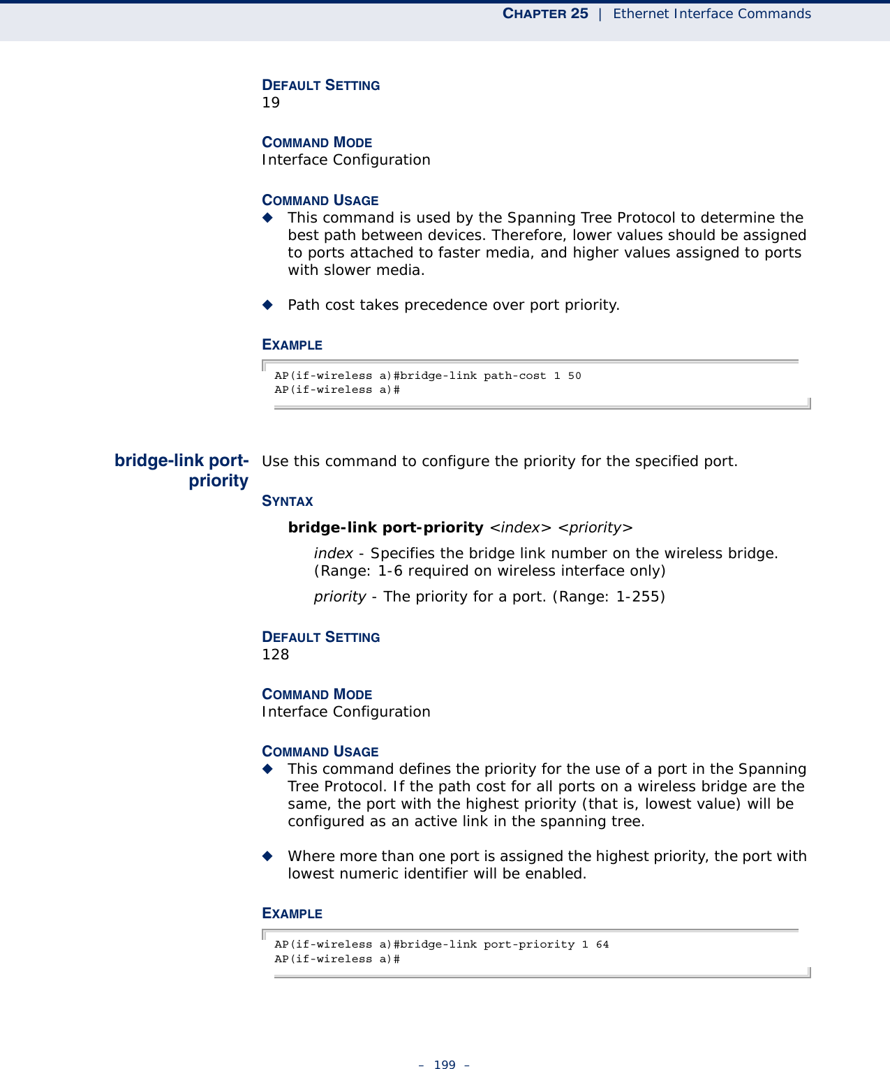
![CHAPTER 25 | Ethernet Interface Commands– 200 –RELATED COMMANDSbridge-link path-cost (198)show interfaceethernetThis command displays the status for the Ethernet interface.SYNTAXshow interface [ethernet]DEFAULT SETTING Ethernet interfaceCOMMAND MODE ExecEXAMPLE AP#show interface ethernetEthernet Interface Information========================================IP Address : 192.168.2.2Subnet Mask : 255.255.255.0Default Gateway : 192.168.1.253Primary DNS : 192.168.1.55Secondary DNS : 10.1.0.55Speed-duplex : 100Base-TX Half DuplexAdmin status : UpOperational status : Up========================================AP#](https://usermanual.wiki/Accton-Technology/E21011/User-Guide-1097647-Page-200.png)
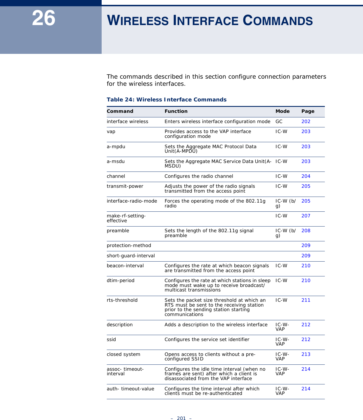
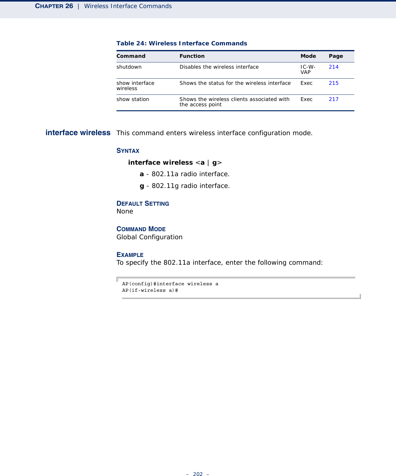
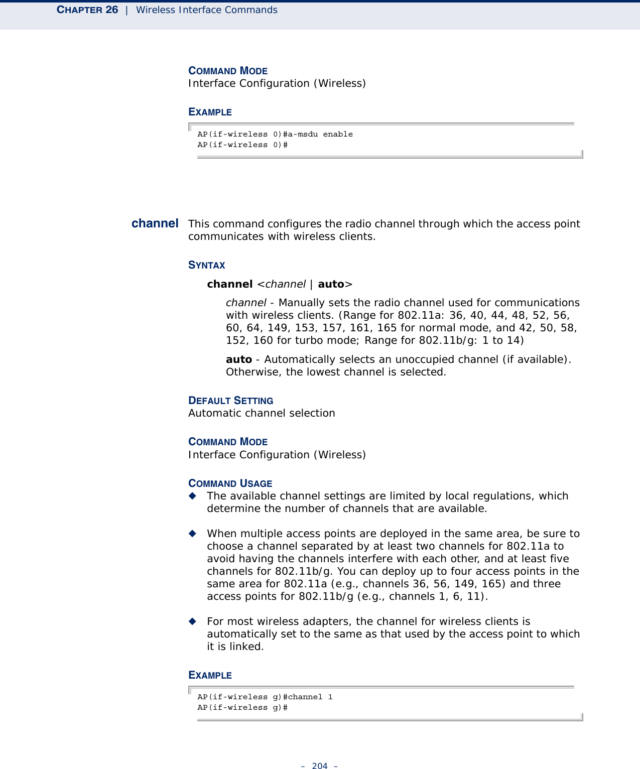
![CHAPTER 26 | Wireless Interface Commands– 203 –vap This command provides access to the VAP (Virtual Access Point) interface configuration mode.SYNTAXvap <vap-id>vap-id - The number that identifies the VAP interface. (Options: 0-7)DEFAULT SETTING NoneCOMMAND MODE Interface Configuration (Wireless)EXAMPLEAP(if-wireless g)#vap 0AP(if-wireless g: VAP[0])#a-mpdu Sets the Aggregate MAC Protocol Data Unit(A-MPDU).SYNTAXa-mpdu <enable | disable | length >length - 1024-65535 seconds.DEFAULT SETTING DisabledCOMMAND MODE Interface Configuration (Wireless)EXAMPLEAP(if-wireless 0)#a-mpdu enableAP(if-wireless 0)#a-msdu Set the Aggregate MAC Service Data Unit(A-MSDU).SYNTAXa-msdu <enable | disable | length >length - 1024-65535 seconds.DEFAULT SETTING Disabled](https://usermanual.wiki/Accton-Technology/E21011/User-Guide-1097647-Page-203.png)
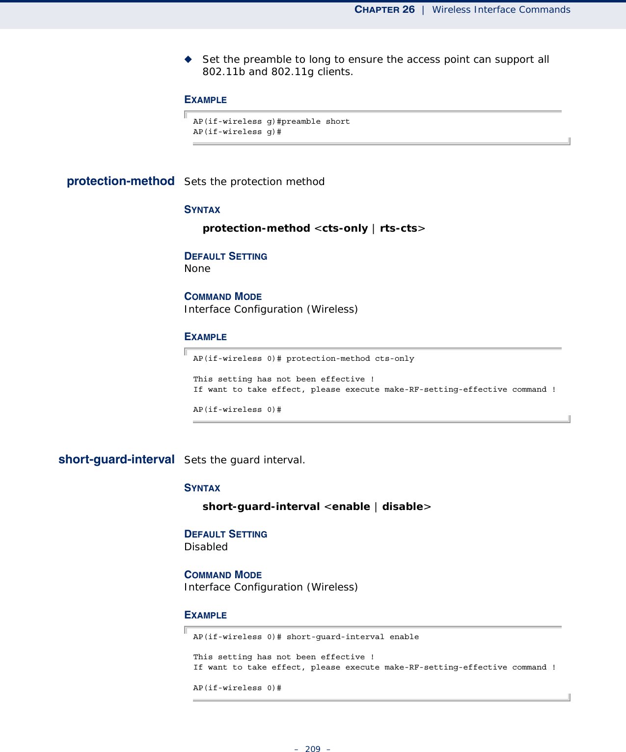
![CHAPTER 26 | Wireless Interface Commands– 208 –ath_vdrv: Version 0.1All Rights Reservedieee80211_ioctl_setmode: CHH Mode: 11NGHT20ath_set_config: Setting ATH parameterath_set_config: Setting ATH parameterath_set_config: Setting ATH parameterieee80211_ioctl_setparam: CHH Calling ieee80211_openieee80211_ioctl_setparam: CHH Calling ieee80211_openath_set_config: Setting ATH parameterath_set_config: Setting ATH parameterieee80211_ioctl_setparam: CHH Calling ieee80211_openieee80211_ioctl_setparam: CHH Calling ieee80211_openath_set_config: Setting ATH parameterForce rf_pwd_icsyndiv to 1 on 2412 (1 0)--AP ar5416InitUserSettings ahp->ah_miscMode 0xcar5416Reset Setting CFG 0x10aHowl Revision ID 0xb9MBSSID Set bit 22 of AR_STA_ID 0xb8c13054Country ie is USIForce rf_pwd_icsyndiv to 2 on 2462 (1 0)--AP ar5416InitUserSettings ahp->ah_miscMode 0xcar5416Reset Setting CFG 0x10aHowl Revision ID 0xb9MBSSID Set bit 22 of AR_STA_ID 0xb8c13054device ath0 entered promiscuous modebr0: port 2(ath0) entering learning statebr0: topology change detected, propagatingbr0: port 2(ath0) entering forwarding stateAdd port ath0 to bridge br0 successfullyath_vdrv: Version 0.1All Rights ReservedAP(if-wireless 0)#preamble This command sets the length of the signal preamble that is used at the start of a 802.11b/g data transmission.SYNTAXpreamble [long | short-or-long]long - Sets the preamble to long (192 microseconds).short-or-long - Sets the preamble to short if no 802.11b clients are detected (96 microseconds).DEFAULT SETTINGShort-or-LongCOMMAND MODEInterface Configuration (Wireless - 802.11b/g)COMMAND USAGE◆Using a short preamble instead of a long preamble can increase data throughput on the access point, but requires that all clients can support a short preamble.](https://usermanual.wiki/Accton-Technology/E21011/User-Guide-1097647-Page-208.png)
![CHAPTER 26 | Wireless Interface Commands– 212 –description This command adds a description to a the wireless interface. Use the no form to remove the description.SYNTAXdescription <string>no descriptionstring - Comment or a description for this interface. (Range: 1-80 characters)DEFAULT SETTING NoneCOMMAND MODE Interface Configuration (Wireless-VAP)EXAMPLEAP(if-wireless g: VAP[0])#description RD-AP#3AP(if-wireless g: VAP[0])#ssid This command configures the service set identifier (SSID). SYNTAXssid <string>string - The name of a basic service set supported by the access point. (Range: 0 - 7 characters)DEFAULT SETTING 802.11a Radio: VAP_TEST_11A (0 to 3)802.11g Radio: VAP_TEST_11G (0 to 3)COMMAND MODE Interface Configuration (Wireless-VAP)COMMAND USAGE Clients that want to connect to the wireless network via an access point must set their SSIDs to the same as that of the access point.EXAMPLEAP(if-wireless g: VAP[0])#ssid RD-AP#3AP(if-wireless g)#](https://usermanual.wiki/Accton-Technology/E21011/User-Guide-1097647-Page-212.png)
![CHAPTER 26 | Wireless Interface Commands– 213 –closed-system This command prohibits access to clients without a pre-configured SSID. Use the no form to disable this feature.SYNTAXclosed-system no closed-systemDEFAULT SETTING DisabledCOMMAND MODE Interface Configuration (Wireless-VAP)COMMAND USAGE When closed system is enabled, the access point will not include its SSID in beacon messages. Nor will it respond to probe requests from clients that do not include a fixed SSID.EXAMPLEAP(if-wireless g: VAP[0])#closed-systemAP(if-wireless g)#](https://usermanual.wiki/Accton-Technology/E21011/User-Guide-1097647-Page-213.png)
![CHAPTER 26 | Wireless Interface Commands– 214 –assoc-timeout-intervalThis command configures the idle time interval (when no frames are sent) after which the client is disassociated from the VAP interface.SYNTAXassoc-timeout-interval <minutes>minutes - The number of minutes of inactivity before disassociation. (Range: 5-60)DEFAULT SETTING 30COMMAND MODE Interface Configuration (Wireless-VAP)EXAMPLEAP(if-wireless g: VAP[0])#association-timeout-interval 20AP(if-wireless g: VAP[0])#auth-timeout-value This command configures the time interval within which clients must complete authentication to the VAP interface.SYNTAXauth-timeout-value <minutes>minutes - The number of minutes before re-authentication. (Range: 5-60)DEFAULT SETTING 60COMMAND MODE Interface Configuration (Wireless-VAP)EXAMPLEAP(if-wireless g: VAP[0])#auth-timeout-value 40AP(if-wireless g: VAP[0])#shutdown This command disables the wireless interface. Use the no form to restart the interface.SYNTAX shutdownno shutdown](https://usermanual.wiki/Accton-Technology/E21011/User-Guide-1097647-Page-214.png)
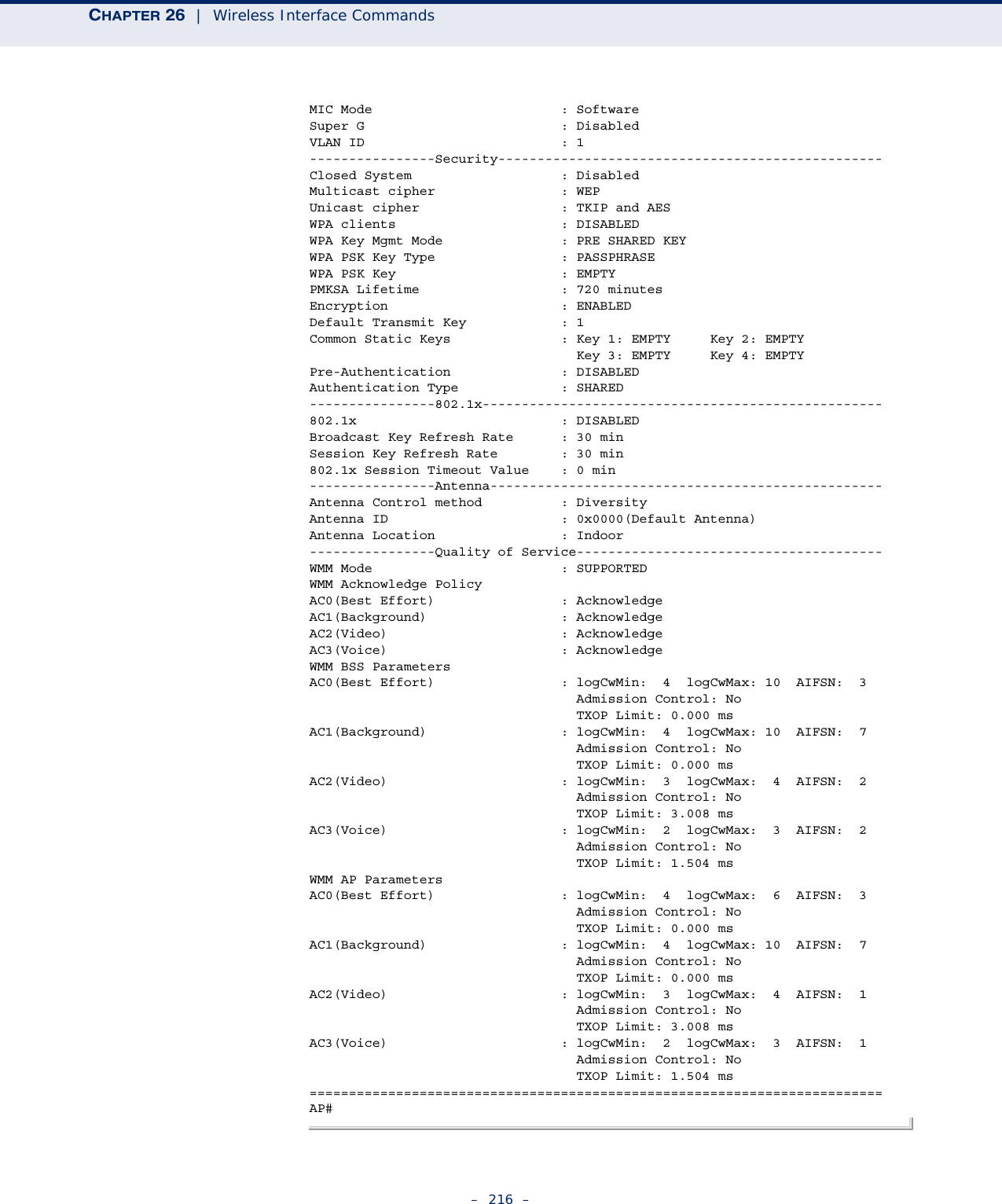
![CHAPTER 26 | Wireless Interface Commands– 215 –DEFAULT SETTING Interface enabledCOMMAND MODE Interface Configuration (Wireless-VAP)COMMAND USAGEYou must first enable VAP interface 0 before you can enable VAP interfaces 1, 2, 3, 4, 5, 6, or 7.EXAMPLE AP(if-wireless g: VAP[0])#shutdownAP(if-wireless g)#show interfacewirelessThis command displays the status for the wireless interface.SYNTAXshow interface wireless <a | g> vap-ida - 802.11a radio interface.g - 802.11g radio interface.vap-id - The number that identifies the VAP interface. (Options: 0~7)COMMAND MODE ExecEXAMPLE AP#show interface wireless g 0Wireless Interface Information=========================================================================----------------Identification-------------------------------------------Description : Enterprise 802.11g Access PointSSID : SMC_VAP_G 0Channel : 1 (AUTO)Status : ENABLEDMAC Address : 00:03:7f:fe:03:02----------------802.11 Parameters----------------------------------------Radio Mode : b & g mixed modeProtection Method : CTS onlyTransmit Power : FULL (16 dBm)Max Station Data Rate : 54MbpsMulticast Data Rate : 5.5MbpsFragmentation Threshold : 2346 bytesRTS Threshold : 2347 bytesBeacon Interval : 100 TUsAuthentication Timeout Interval : 60 MinsAssociation Timeout Interval : 30 MinsDTIM Interval : 1 beaconPreamble Length : LONGMaximum Association : 64 stations](https://usermanual.wiki/Accton-Technology/E21011/User-Guide-1097647-Page-215.png)
![CHAPTER 26 | Wireless Interface Commands– 217 –show station This command shows the wireless clients associated with the access point.COMMAND MODE ExecEXAMPLE AP#show stationStation Table Information========================================================if-wireless A VAP [0] :802.11a Channel : 60No 802.11a Channel Stations....if-wireless G VAP [0] :802.11g Channel : 1802.11g Channel Station TableStation Address : 00-04-23-94-9A-9C VLAN ID: 0Authenticated Associated Forwarding KeyTypeTRUE FALSE FALSE NONECounters:pkts Tx / Rx bytes Tx / Rx 20/ 0 721/ 0Time:Associated LastAssoc LastDisAssoc LastAuth 0 0 0 0if-wireless G VAP [1] :802.11g Channel : 1No 802.11g Channel Stations....AP#](https://usermanual.wiki/Accton-Technology/E21011/User-Guide-1097647-Page-217.png)
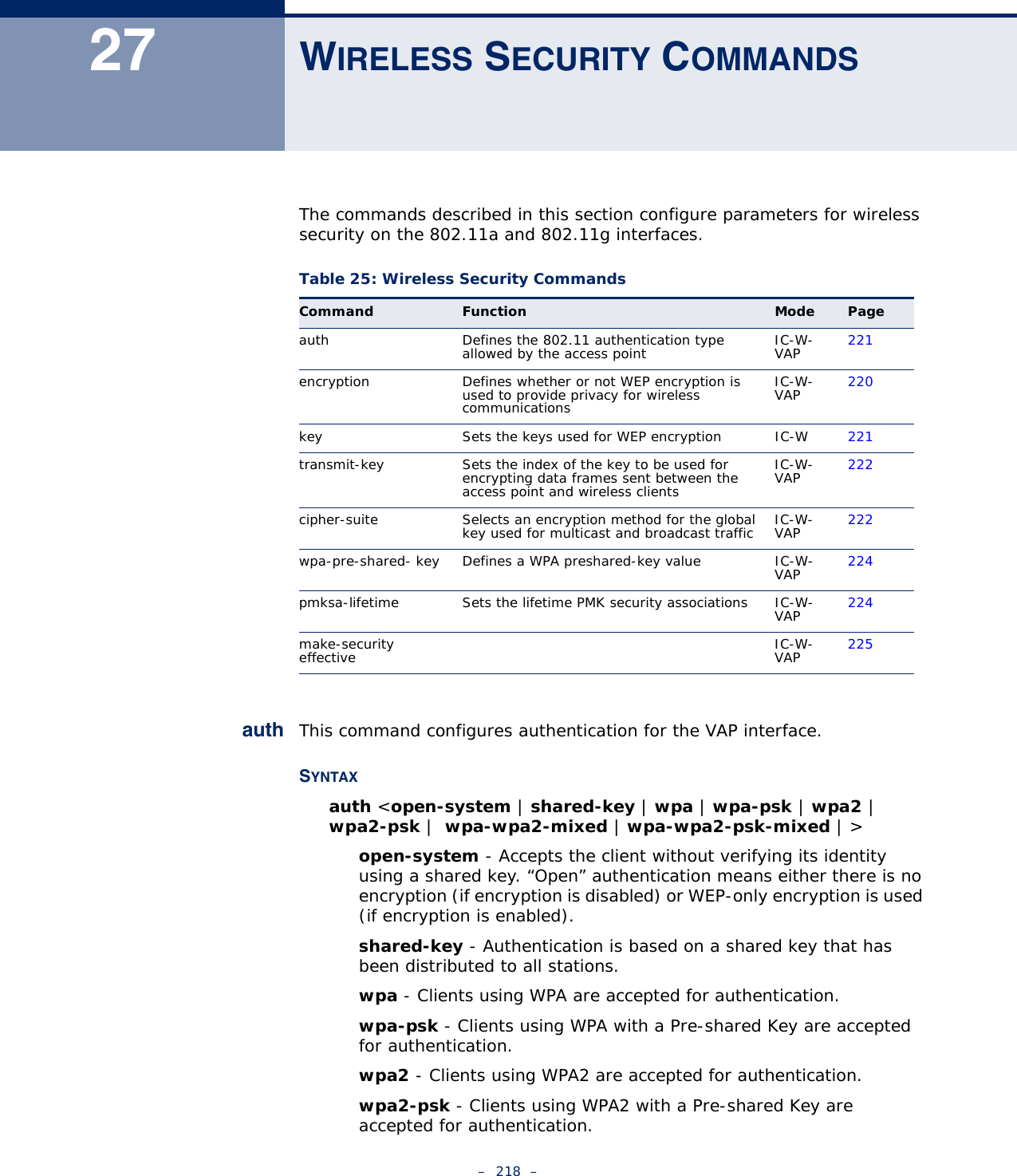
![CHAPTER 27 | Wireless Security Commands– 220 –encryption cipher suite is set to TKIP, the unicast encryption cipher (TKIP or AES-CCMP) is negotiated for each client. The access point advertises it’s supported encryption ciphers in beacon frames and probe responses. WPA and WPA2 clients select the cipher they support and return the choice in the association request to the access point. For mixed-mode operation, the cipher used for broadcast frames is always TKIP. WEP encryption is not allowed.EXAMPLEAP(if-wireless g: VAP[0])#auth shared-keyAP(if-wireless g)#RELATED COMMANDSencryption (220)key (221)encryption This command enables data encryption for wireless communications. Use the no form to disable data encryption.SYNTAXencryptionno encryptionDEFAULT SETTING disabledCOMMAND MODE Interface Configuration (Wireless-VAP)COMMAND USAGE ◆Wired Equivalent Privacy (WEP) is implemented in this device to prevent unauthorized access to your wireless network. For more secure data transmissions, enable encryption with this command, and set at least one static WEP key with the key command. ◆The WEP settings must be the same on each client in your wireless network.◆Note that WEP protects data transmitted between wireless nodes, but does not protect any transmissions over your wired network or over the Internet.◆You must enable data encryption in order to enable all types of encryption (WEP, TKIP, and AES-CCMP) in the access point.](https://usermanual.wiki/Accton-Technology/E21011/User-Guide-1097647-Page-220.png)
![CHAPTER 27 | Wireless Security Commands– 221 –EXAMPLEAP(if-wireless g: VAP[0])#encryptionAP(if-wireless g)#RELATED COMMANDSkey (221)key This command sets the keys used for WEP encryption. Use the no form to delete a configured key.SYNTAXkey <1-4> <static> <dynamic>no key1-4 - Key index. (Range: 1-4)static - Indicates a static key.dynamic - Indicates a dynamic key.value - The key string.For 64-bit keys, use 5 alphanumeric characters or 10 hexadecimal digits.For 128-bit keys, use 13 alphanumeric characters or 26 hexadecimal digits.For 152-bit keys, use 16 alphanumeric characters or 32 hexadecimal digits.DEFAULT SETTING NoneCOMMAND MODE Interface Configuration (Wireless)COMMAND USAGE ◆To enable Wired Equivalent Privacy (WEP), use the auth shared-key command to select the “shared key” authentication type, use the key command to configure at least one key, and use the transmit-key command to assign a key to one of the VAP interfaces.◆If WEP option is enabled, all wireless clients must be configured with the same shared keys to communicate with the access point.◆The encryption index, length and type configured in the access point must match those configured in the clients.EXAMPLEAP(if-wireless 0)#key 1 64 hex 1234512345AP(if-wireless 0)#key 2 128 ascii asdeipadjsipd](https://usermanual.wiki/Accton-Technology/E21011/User-Guide-1097647-Page-221.png)
![CHAPTER 27 | Wireless Security Commands– 222 –AP(if-wireless 0)#key 3 64 hex 12345123451234512345123456AP(if-wireless 0)#RELATED COMMANDSkey (221)encryption (220)transmit-key (222)transmit-key This command sets the index of the key to be used for encrypting data frames for broadcast or multicast traffic transmitted from the VAP to wireless clients.SYNTAXtransmit-key <index>index - Key index. (Range: 1-4)DEFAULT SETTING 1COMMAND MODE Interface Configuration (Wireless-VAP)COMMAND USAGE ◆If you use WEP key encryption option, the access point uses the transmit key to encrypt multicast and broadcast data signals that it sends to client devices. Other keys can be used for decryption of data from clients.◆When using IEEE 802.1X, the access point uses a dynamic key to encrypt unicast and broadcast messages to 802.1X-enabled clients. However, because the access point sends the keys during the 802.1X authentication process, these keys do not have to appear in the client’s key list.◆In a mixed-mode environment with clients using static and dynamic keys, select transmit key index 2, 3, or 4. The access point uses transmit key index 1 for the generation of dynamic keys.EXAMPLEAP(if-wireless g: VAP[0])#transmit-key 2AP(if-wireless g)# cipher-suite This command defines the cipher algorithm used to encrypt the global key for broadcast and multicast traffic when using Wi-Fi Protected Access (WPA) security.](https://usermanual.wiki/Accton-Technology/E21011/User-Guide-1097647-Page-222.png)
![CHAPTER 27 | Wireless Security Commands– 223 –SYNTAXmulticast-cipher <aes-ccmp | tkip >aes-ccmp - Use AES-CCMP encryption for the unicast and multicast cipher.tkip - Use TKIP encryption for the multicast cipher. TKIP or AES-CCMP can be used for the unicast cipher depending on the capability of the client. DEFAULT SETTING NoneCOMMAND MODE Interface Configuration (Wireless-VAP)COMMAND USAGE ◆WPA enables the access point to support different unicast encryption keys for each client. However, the global encryption key for multicast and broadcast traffic must be the same for all clients.◆TKIP provides data encryption enhancements including per-packet key hashing (i.e., changing the encryption key on each packet), a message integrity check, an extended initialization vector with sequencing rules, and a re-keying mechanism. Select TKIP if there are clients in the network that are not WPA2 compliant.◆TKIP defends against attacks on WEP in which the unencrypted initialization vector in encrypted packets is used to calculate the WEP key. TKIP changes the encryption key on each packet, and rotates not just the unicast keys, but the broadcast keys as well. TKIP is a replacement for WEP that removes the predictability that intruders relied on to determine the WEP key. ◆AES-CCMP (Advanced Encryption Standard Counter-Mode/CBCMAC Protocol): WPA2 is backward compatible with WPA, including the same 802.1X and PSK modes of operation and support for TKIP encryption. The main enhancement is its use of AES Counter-Mode encryption with Cipher Block Chaining Message Authentication Code (CBC-MAC) for message integrity. The AES Counter-Mode/CBCMAC Protocol (AES-CCMP) provides extremely robust data confidentiality using a 128-bit key. The AES-CCMP encryption cipher is specified as a standard requirement for WPA2. However, the computational intensive operations of AES-CCMP requires hardware support on client devices. Therefore to implement WPA2 in the network, wireless clients must be upgraded to WPA2-compliant hardware.EXAMPLEAP(if-wireless g: VAP[0])#multicast-cipher TKIPAP(if-wireless g)#](https://usermanual.wiki/Accton-Technology/E21011/User-Guide-1097647-Page-223.png)
![CHAPTER 27 | Wireless Security Commands– 224 –wpa-pre-shared-key This command defines a Wi-Fi Protected Access (WPA/WPA2) Pre-shared-key.SYNTAXwpa-pre-shared-key <hex | passphrase-key> <value>hex - Specifies hexadecimal digits as the key input format.passphrase-key - Specifies an ASCII pass-phrase string as the key input format.value - The key string. For ASCII input, specify a string between 8 and 63 characters. For HEX input, specify exactly 64 digits.COMMAND MODE Interface Configuration (Wireless-VAP)COMMAND USAGE ◆To support WPA or WPA2 for client authentication, use the auth command to specify the authentication type, and use the wpa-preshared-key command to specify one static key.◆If WPA or WPA2 is used with pre-shared-key mode, all wireless clients must be configured with the same pre-shared key to communicate with the access point’s VAP interface.EXAMPLEAP(if-wireless g: VAP[0])#wpa-pre-shared-key ASCII agoodsecretAP(if-wireless g)# RELATED COMMANDSauth (218)pmksa-lifetime This command sets the time for aging out cached WPA2 Pairwise Master Key Security Association (PMKSA) information for fast roaming.SYNTAXpmksa-lifetime <minutes>minutes - The time for aging out PMKSA information. (Range: 0 -14400 minutes)DEFAULT SETTING 720 minutesCOMMAND MODE Interface Configuration (Wireless-VAP)](https://usermanual.wiki/Accton-Technology/E21011/User-Guide-1097647-Page-224.png)
![CHAPTER 27 | Wireless Security Commands– 225 –COMMAND USAGE ◆WPA2 provides fast roaming for authenticated clients by retaining keys and other security information in a cache, so that if a client roams away from an access point and then returns reauthentication is not required. ◆When a WPA2 client is first authenticated, it receives a Pairwise Master Key (PMK) that is used to generate other keys for unicast data encryption. This key and other client information form a Security Association that the access point names and holds in a cache. The lifetime of this security association can be configured with this command. When the lifetime expires, the client security association and keys are deleted from the cache. If the client returns to the access point, it requires full reauthentication.◆The access point can store up to 256 entries in the PMKSA cache. EXAMPLEAP(if-wireless g: VAP[0])#wpa-pre-shared-key ASCII agoodsecretAP(if-wireless g: VAP[0])# make-security-effectiveThis command does something.SYNTAXmake-security-effectiveDEFAULT SETTING DisabledCOMMAND MODE Interface Configuration (Wireless-VAP)EXAMPLEAP(IF-WIRELESS 0: VAP[0])# MAKE-SECURITY-EFFECTIVEIT WILL TAKE SEVERAL MINUTES !PLEASE WAIT A WHILE...device ath0 left promiscuous modebr0: port 2(ath0) entering disabled stateDelete port ath0 from bridge br0 successfullyath_netdev_stop: The stopping of the runningar5416StopDmaReceive: dma failed to stop in 1msAR_CR=0x00000024AR_DIAG_SW=0x40000020ath_vdrv: driver unloadedwlan: mac acl policy unregisteredath_ahb: driver unloadedath_dev: driver unloadedath_dfs: driver unloadedath_rate_atheros: driver unloadedwlan: driver unloadedath_hal: driver unloaded](https://usermanual.wiki/Accton-Technology/E21011/User-Guide-1097647-Page-225.png)
![CHAPTER 27 | Wireless Security Commands– 227 –BR0 NO WIRELESS EXTENSIONS.WIFI0 NO WIRELESS EXTENSIONS.LO NO WIRELESS EXTENSIONS.ETH0 NO WIRELESS EXTENSIONS.BR0 NO WIRELESS EXTENSIONS.WIFI0 NO WIRELESS EXTENSIONS.LO NO WIRELESS EXTENSIONS.ETH0 NO WIRELESS EXTENSIONS.BR0 NO WIRELESS EXTENSIONS.WIFI0 NO WIRELESS EXTENSIONS.ieee80211_ioctl_setmode: CHH Mode: 11NAHT20ath_set_config: Setting ATH parameterath_set_config: Setting ATH parameterath_set_config: Setting ATH parameterieee80211_ioctl_setparam: CHH Calling ieee80211_openERROR FOR WIRELESS REQUEST "SET FRAGMENTATION THRESHOLD" (8B24) : SET FAILED ON DEVICE ATH0 ; INVALID ARGUMENT.ieee80211_ioctl_setparam: CHH Calling ieee80211_openath_set_config: Setting ATH parameterath_set_config: Setting ATH parameterieee80211_ioctl_setparam: CHH Calling ieee80211_openieee80211_ioctl_setparam: CHH Calling ieee80211_open[: ADDED ATH0 MODE MASTERCREATED ATH0 MODE AP FOR SMC_VAP_0: BAD NUMBERath_set_config: Setting ATH parameter--AP ar5416InitUserSettings ahp->ah_miscMode 0xcar5416Reset Setting CFG 0x10aHowl Revision ID 0xb9MBSSID Set bit 22 of AR_STA_ID 0xb8c13054Country ie is USI--AP ar5416InitUserSettings ahp->ah_miscMode 0xcar5416Reset Setting CFG 0x10aHowl Revision ID 0xb9MBSSID Set bit 22 of AR_STA_ID 0xb8c13054device ath0 entered promiscuous modebr0: port 2(ath0) entering learning statebr0: topology change detected, propagatingbr0: port 2(ath0) entering forwarding stateAdd port ath0 to bridge br0 successfullyATH0 LINK ENCAP:ETHERNET HWADDR 02:12:CF:A2:54:30KILLALL: UDHCPC: NO PROCESS KILLEDCLOSE VAP MULTI CAST WHEN VAP MODE IS WDS-STA, BUT STP IS DISABLEDath_vdrv: Version 0.1All Rights ReservedAP(IF-WIRELESS 0: VAP[0])#](https://usermanual.wiki/Accton-Technology/E21011/User-Guide-1097647-Page-227.png)
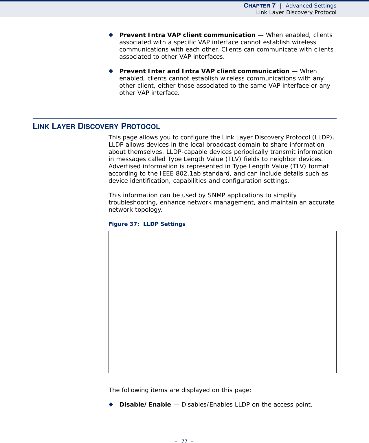
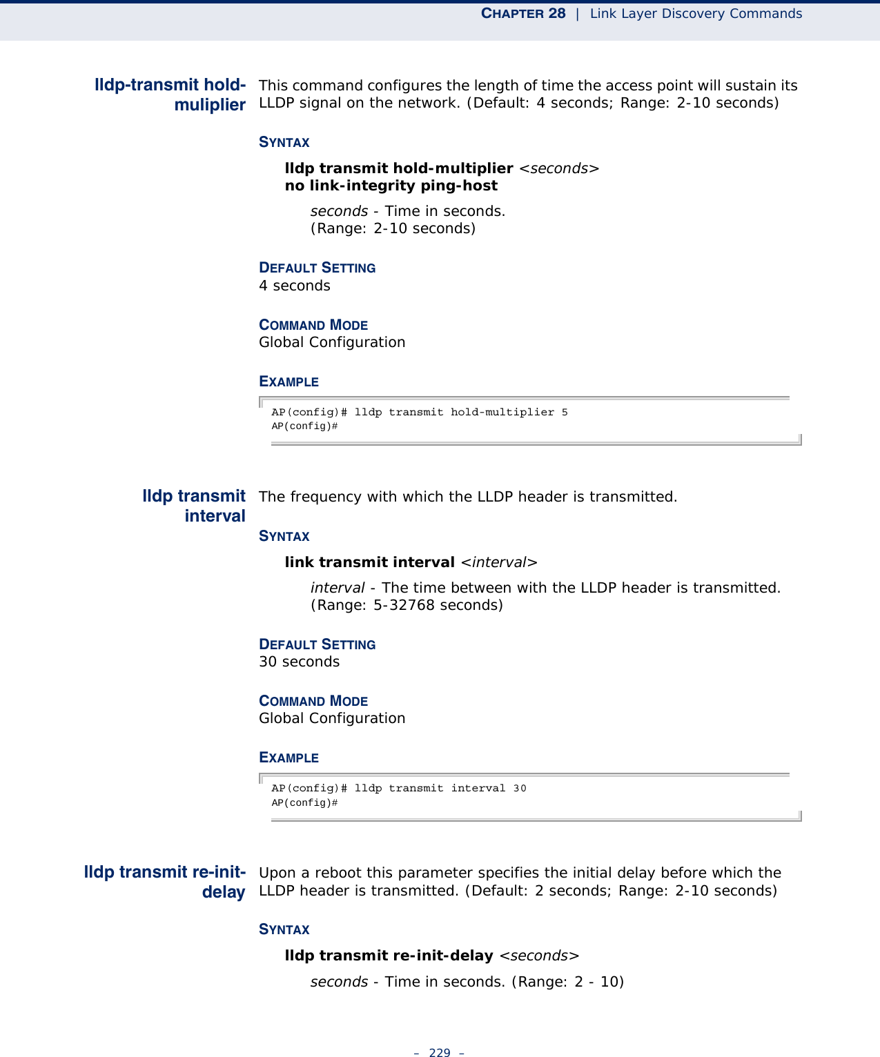
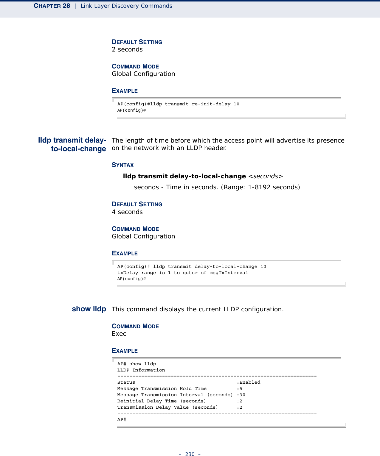
![– 228 –28 LINK LAYER DISCOVERY COMMANDSLLDP allows devices in the local broadcast domain to share information about themselves. LLDP-capable devices periodically transmit information in messages called Type Length Value (TLV) fields to neighbor devices. Advertised information is represented in Type Length Value (TLV) format according to the IEEE 802.1ab standard, and can include details such as device identification, capabilities and configuration settings.This information can be used by SNMP applications to simplify troubleshooting, enhance network management, and maintain an accurate network topology.lldp service This command enables LLDP on the access point. Use the no form to disable LLDP.SYNTAX[no] link-integrity ping-detectDEFAULT SETTINGDisabledCOMMAND MODE Global ConfigurationEXAMPLEAP(config)# lldp serviceAP(config)# Table 26: Link Layer Discovery CommandsCommand Function Mode Pagelldp service Enables the transmission of LLDP information GC 228lldp transmit hold-muliplier Sets the message transmission hold time GC 229lldp transmit interval Sets the message transmission interval time GC 229lldp transmit re-init-delay Sets the reinitial delay time GC 229lldp transmit delay-to-local-change Sets the transmission delay value GC 230show lldp Shows the current LLDP information Exec 230](https://usermanual.wiki/Accton-Technology/E21011/User-Guide-1097647-Page-228.png)

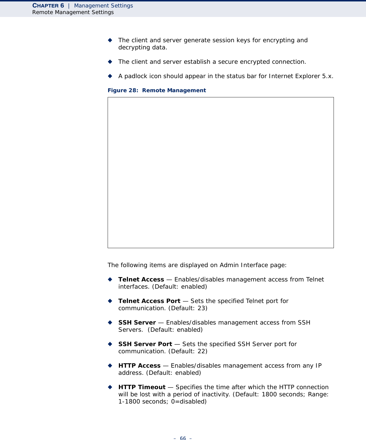
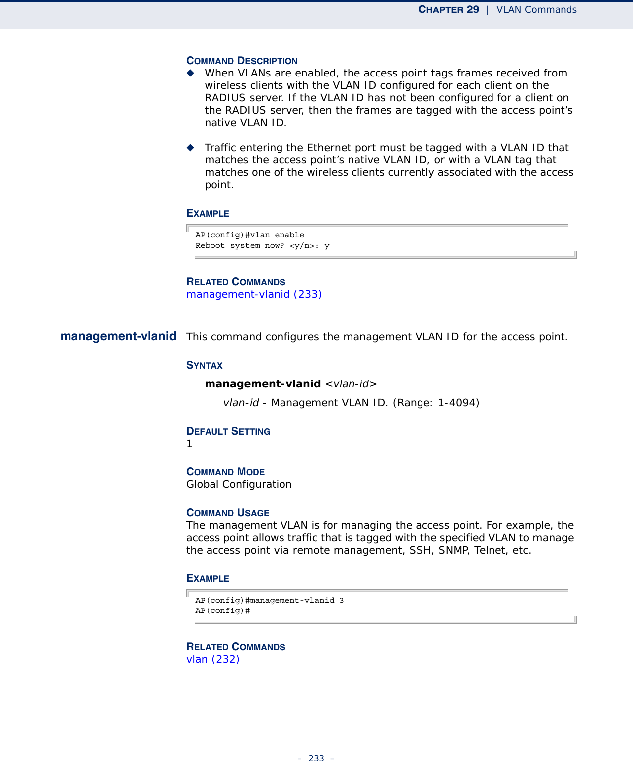
![– 232 –29 VLAN COMMANDSThe access point can enable the support of VLAN-tagged traffic passing between wireless clients and the wired network. Up to 64 VLAN IDs can be mapped to specific wireless clients, allowing users to remain within the same VLAN as they move around a campus site.When VLAN is enabled on the access point, a VLAN ID (a number between 1 and 4094) can be assigned to each client after successful authentication using IEEE 802.1X and a central RADIUS server. The user VLAN IDs must be configured on the RADIUS server for each user authorized to access the network. If a user does not have a configured VLAN ID, the access point assigns the user to its own configured native VLAN ID.CAUTION: When VLANs are enabled, the access point’s Ethernet port drops all received traffic that does not include a VLAN tag. To maintain network connectivity to the access point and wireless clients, be sure that the access point is connected to a device port on a wired network that supports IEEE 802.1Q VLAN tags.The VLAN commands supported by the access point are listed below.vlan This command enables VLANs for all traffic. Use the no form to disable VLANs.SYNTAX[no] vlan enable DEFAULTDisabledCOMMAND MODEGlobal ConfigurationTable 27: VLAN CommandsCommand Function Mode Pagevlan Enables a single VLAN for all traffic GC 232management-vlanid Configures the management VLAN for the access point GC 233vlan-id Configures the default VLAN for the VAP interface IC-W-VAP 234](https://usermanual.wiki/Accton-Technology/E21011/User-Guide-1097647-Page-232.png)
![CHAPTER 29 | VLAN Commands– 234 –vlan-id This command configures the default VLAN ID for the VAP interface. SYNTAXvlan-id <vlan-id>vlan-id - Native VLAN ID. (Range: 1-4094)DEFAULT SETTING 1COMMAND MODE Interface Configuration (Wireless-VAP)COMMAND USAGE ◆To implement the default VLAN ID setting for VAP interface, the access point must enable VLAN support using the vlan command.◆When VLANs are enabled, the access point tags frames received from wireless clients with the default VLAN ID for the VAP interface. If IEEE 802.1X is being used to authenticate wireless clients, specific VLAN IDs can be configured on the RADIUS server to be assigned to each client. Using IEEE 802.1X and a central RADIUS server, up to 64 VLAN IDs can be mapped to specific wireless clients.◆If the VLAN ID has not been configured for a client on the RADIUS server, then the frames are tagged with the default VLAN ID of the VAP interface.EXAMPLEAP(if-wireless g: VAP[0])#vlan-id 3AP(if-wireless g: VAP[0])#](https://usermanual.wiki/Accton-Technology/E21011/User-Guide-1097647-Page-234.png)
![– 235 –30 WMM COMMANDSThe access point implements QoS using the Wi-Fi Multimedia (WMM) standard. Using WMM, the access point is able to prioritize traffic and optimize performance when multiple applications compete for wireless network bandwidth at the same time. WMM employs techniques that are a subset of the developing IEEE 802.11e QoS standard and it enables the access point to inter-operate with both WMM- enabled clients and other devices that may lack any WMM functionality.The WMM commands supported by the access point are listed below.wmm This command sets the WMM operational mode on the access point. Use the no form to disable WMM.SYNTAX[no] wmm <required> required - WMM must be supported on any device trying to associated with the access point. Devices that do not support this feature will not be allowed to associate with the access point. DEFAULTsupportedCOMMAND MODEInterface Configuration (Wireless)EXAMPLEAP(if-wireless a)#wmm requiredAP(if-wireless a)#Table 28: WMM CommandsCommand Function Mode Pagewmm Sets the WMM operational mode on the access point IC-W 235wmm-acknowledge- policy Allows the acknowledgement wait time to be enabled or disabled for each Access Category (AC)IC-W 236wmmparam Configures detailed WMM parameters that apply to the access point (AP) or the wireless clients (BSS)IC-W 236](https://usermanual.wiki/Accton-Technology/E21011/User-Guide-1097647-Page-235.png)