Accton Technology E21011 Draft 11n Dual band Wireless Access Point User Manual user guide
Accton Technology Corp Draft 11n Dual band Wireless Access Point user guide
User manual

USER GUIDE
EliteConnectTM SMCE21011
802.11b/g/n AP
SMCE21011

20 Mason
Irvine, CA 92618
Phone: (949) 679-8000
EliteConnectTM SMCE21011
User Guide
April 2009
Pub. # XXXXXXXXXXX
E042009-DT-R01
Information furnished by SMC Networks, Inc. (SMC) is believed to be accurate and reliable.
However, no responsibility is assumed by SMC for its use, nor for any infringements of patents or
other rights of third parties which may result from its use. No license is granted by implication or
otherwise under any patent or patent rights of SMC. SMC reserves the right to change specifications
at any time without notice.
Copyright © 2009 by
SMC Networks, Inc.
20 Mason
Irvine, CA 92618
All rights reserved
Trademarks:
SMC is a registered trademark; and EZ Switch, TigerStack, TigerSwitch, and TigerAccess are
trademarks of SMC Networks, Inc. Other product and company names are trademarks or registered
trademarks of their respective holders.
– 4 –
LIMITED WARRANTY
Limited Warranty Statement: SMC Networks, Inc. (“SMC”) warrants its
products to be free from defects in workmanship and materials, under
normal use and service, for the applicable warranty term. All SMC products
carry a standard 90-day limited warranty from the date of purchase from
SMC or its Authorized Reseller. SMC may, at its own discretion, repair or
replace any product not operating as warranted with a similar or
functionally equivalent product, during the applicable warranty term. SMC
will endeavor to repair or replace any product returned under warranty
within 30 days of receipt of the product.
The standard limited warranty can be upgraded to a Limited Lifetime*
warranty by registering new products within 30 days of purchase from SMC
or its Authorized Reseller. Registration can be accomplished via the
enclosed product registration card or online via the SMC Web site. Failure
to register will not affect the standard limited warranty. The Limited
Lifetime warranty covers a product during the Life of that Product, which is
defined as the period of time during which the product is an “Active” SMC
product. A product is considered to be “Active” while it is listed on the
current SMC price list. As new technologies emerge, older technologies
become obsolete and SMC will, at its discretion, replace an older product in
its product line with one that incorporates these newer technologies. At
that point, the obsolete product is discontinued and is no longer an “Active”
SMC product. A list of discontinued products with their respective dates of
discontinuance can be found at:
http://www.smc.com/index.cfm?action=customer_service_warranty
.
All products that are replaced become the property of SMC. Replacement
products may be either new or reconditioned. Any replaced or repaired
product carries either a 30-day limited warranty or the remainder of the
initial warranty, whichever is longer. SMC is not responsible for any custom
software or firmware, configuration information, or memory data of
Customer contained in, stored on, or integrated with any products returned
to SMC pursuant to any warranty. Products returned to SMC should have
any customer-installed accessory or add-on components, such as
expansion modules, removed prior to returning the product for
replacement. SMC is not responsible for these items if they are returned
with the product.
Customers must contact SMC for a Return Material Authorization number
prior to returning any product to SMC. Proof of purchase may be required.
Any product returned to SMC without a valid Return Material Authorization
(RMA) number clearly marked on the outside of the package will be
returned to customer at customer’s expense. For warranty claims within
North America, please call our toll-free customer support number at (800)
762-4968. Customers are responsible for all shipping charges from their
facility to SMC. SMC is responsible for return shipping charges from SMC to
customer.
WARRANTIES EXCLUSIVE: IF AN SMC PRODUCT DOES NOT OPERATE AS
WARRANTED ABOVE, CUSTOMER’S SOLE REMEDY SHALL BE REPAIR OR
REPLACEMENT OF THE PRODUCT IN QUESTION, AT SMC’S OPTION. THE
FOREGOING WARRANTIES AND REMEDIES ARE EXCLUSIVE AND ARE IN
– 5 –
LIEU OF ALL OTHER WARRANTIES OR CONDITIONS, EXPRESS OR
IMPLIED, EITHER IN FACT OR BY OPERATION OF LAW, STATUTORY OR
OTHERWISE, INCLUDING WARRANTIES OR CONDITIONS OF
MERCHANTABILITY AND FITNESS FOR A PARTICULAR PURPOSE. SMC
NEITHER ASSUMES NOR AUTHORIZES ANY OTHER PERSON TO ASSUME
FOR IT ANY OTHER LIABILITY IN CONNECTION WITH THE SALE,
INSTALLATION, MAINTENANCE OR USE OF ITS PRODUCTS. SMC SHALL
NOT BE LIABLE UNDER THIS WARRANTY IF ITS TESTING AND
EXAMINATION DISCLOSE THE ALLEGED DEFECT IN THE PRODUCT DOES
NOT EXIST OR WAS CAUSED BY CUSTOMER’S OR ANY THIRD PERSON’S
MISUSE, NEGLECT, IMPROPER INSTALLATION OR TESTING,
UNAUTHORIZED ATTEMPTS TO REPAIR, OR ANY OTHER CAUSE BEYOND
THE RANGE OF THE INTENDED USE, OR BY ACCIDENT, FIRE, LIGHTNING,
OR OTHER HAZARD.
LIMITATION OF LIABILITY: IN NO EVENT, WHETHER BASED IN CONTRACT
OR TORT (INCLUDING NEGLIGENCE), SHALL SMC BE LIABLE FOR
INCIDENTAL, CONSEQUENTIAL, INDIRECT, SPECIAL, OR PUNITIVE
DAMAGES OF ANY KIND, OR FOR LOSS OF REVENUE, LOSS OF BUSINESS,
OR OTHER FINANCIAL LOSS ARISING OUT OF OR IN CONNECTION WITH
THE SALE, INSTALLATION, MAINTENANCE, USE, PERFORMANCE, FAILURE,
OR INTERRUPTION OF ITS PRODUCTS, EVEN IF SMC OR ITS AUTHORIZED
RESELLER HAS BEEN ADVISED OF THE POSSIBILITY OF SUCH DAMAGES.
SOME STATES DO NOT ALLOW THE EXCLUSION OF IMPLIED WARRANTIES
OR THE LIMITATION OF INCIDENTAL OR CONSEQUENTIAL DAMAGES FOR
CONSUMER PRODUCTS, SO THE ABOVE LIMITATIONS AND EXCLUSIONS
MAY NOT APPLY TO YOU. THIS WARRANTY GIVES YOU SPECIFIC LEGAL
RIGHTS, WHICH MAY VARY FROM STATE TO STATE. NOTHING IN THIS
WARRANTY SHALL BE TAKEN TO AFFECT YOUR STATUTORY RIGHTS.
* SMC will provide warranty service for one year following discontinuance
from the active SMC price list. Under the limited lifetime warranty, internal
and external power supplies, fans, and cables are covered by a standard
one-year warranty from date of purchase.
SMC Networks, Inc.
20 Mason
Irvine, CA 92618
– 6 –

– 7 –
COMPLIANCES
FEDERAL COMMUNICATION COMMISSION INTERFERENCE STATEMENT
This equipment has been tested and found to comply with the limits for a
Class B digital device, pursuant to Part 15 of the FCC Rules. These limits
are designed to provide reasonable protection against harmful interference
in a residential installation. This equipment generates, uses and can
radiate radio frequency energy and, if not installed and used in accordance
with the instructions, may cause harmful interference to radio
communications. However, there is no guarantee that interference will not
occur in a particular installation. If this equipment does cause harmful
interference to radio or television reception, which can be determined by
turning the equipment off and on, the user is encouraged to try to correct
the interference by one of the following measures:
◆Reorient or relocate the receiving antenna
◆Increase the separation between the equipment and receiver
◆Connect the equipment into an outlet on a circuit different from that to
which the receiver is connected
◆Consult the dealer or an experienced radio/TV technician for help
This device complies with Part 15 of the FCC Rules. Operation is subject to
the following two conditions: (1) This device may not cause harmful
interference, and (2) this device must accept any interference received,
including interference that may cause undesired operation.
FCC Caution: Any changes or modifications not expressly approved by the
party responsible for compliance could void the user's authority to operate
this equipment.
For product available in the USA/Canada market, only channel 1~11 can be
operated. Selection of other channels is not possible.
This device and its antenna(s) must not be co-located or operation in
conjunction with any other antenna or transmitter.
This device is going to be operated in 5.15~5.25GHz frequency range, it is
restricted in indoor environment only.

A
BOUT
T
HIS
G
UIDE
– 8 –
IMPORTANT NOTE:
FCC RADIATION EXPOSURE STATEMENT
This equipment complies with FCC radiation exposure limits set forth for an
uncontrolled environment. This equipment should be installed and
operated with minimum distance 20 cm between the radiator & your body.
IC STATEMENT :
This Class B digital apparatus complies with Canadian ICES-003.
Operation is subject to the following two conditions: (1) this device may
not cause interference, and (2) this device must accept any interference,
including interference that may cause undesired operation of the device.
Cet appareil numérique de la classe B conforme á la norme NMB-003 du
Canada.
To reduce potential radio interference to other users, the antenna type and
its gain should be so chosen that the equivalent isotropically radiated
power (e.i.r.p) is not more than that permitted for successful
communication.
This device has been designed to operate with the antennas listed below,
and having a maximum gain of [5] dB. Antennas not included in this list or
having a gain greater than [5] dB are strictly prohibited for use with this
device. The required antenna impedance is 50 ohms.
The device could automatically discontinue transmission in case of absence
of information to transmit, or operational failure. Note that this is not
intended to prohibit transmission of control or signaling information or the
use of repetitive codes where required by the technology.
The device for the band 5150-5250 MHz is only for indoor usage to reduce
potential for harmful interference to co-channel mobile satellite systems.
The maximum antenna gain permitted (for devices in the band 5725-5825
MHz) to comply with the e.i.r.p. limits specified for point-to-point and non
point-to-point operation as appropriate, as stated in section A9.2(3).
IMPORTANT NOTE:
IC Radiation Exposure Statement:
This equipment complies with IC RSS-102 radiation exposure limits set
forth for an uncontrolled environment. This equipment should be installed
and operated with minimum distance 20 cm between the radiator & your
body.
A
BOUT
T
HIS
G
UIDE
– 9 –
AUSTRALIA/NEW ZEALAND AS/NZS 4771
JAPAN VCCI CLASS B
TAIWAN NCC
根據交通部低功率管理辦法規定:
第十二條 經型式認證合格之低功率射頻電機,非經許可,公司、商號或使用者均不得擅自變更
頻率、加大功率或變更原設計之特性及功能。
第十四條 低功率射頻電機之使用不得影響飛航安全及干擾合法通信;經發現有干擾現象時,應
立即停用,並改善至無干擾時方得繼續使用。前項合法通信,指依電信法規定作業之無線電通
信。低功率射頻電機須忍受合法通信或工業、科學及醫療用電波輻射性電機設備之干擾。
EC CONFORMANCE DECLARATION
Marking by the above symbol indicates compliance with the Essential
Requirements of the R&TTE Directive of the European Union (1999/5/EC).
This equipment meets the following conformance standards:
◆EN 60950-1 (IEC 60950-1) - Product Safety
◆EN 301 893 - Technical requirements for 5 GHz radio equipment
◆EN 300 328 - Technical requirements for 2.4 GHz radio equipment
◆EN 301 489-1 / EN 301 489-17 - EMC requirements for radio
equipment
This device is intended for use in the following European Community and
EFTA countries:
Requirements for indoor vs. outdoor operation, license requirements and
allowed channels of operation apply in some countries as described below:
◆Austria ◆Belgium ◆Cyprus ◆Czech Republic ◆Denmark
◆Estonia ◆Finland ◆France ◆Germany ◆Greece
◆Hungary ◆Iceland ◆Ireland ◆Italy ◆Latvia
◆Liechtenstein ◆Lithuania ◆Luxembourg ◆Malta ◆Netherlands
◆Norway ◆Poland ◆Portugal ◆Slovakia ◆Slovenia
◆Spain ◆Sweden ◆Switzerland ◆United Kingdom ◆
ACN 066 352010
A
BOUT
T
HIS
G
UIDE
– 10 –
◆In Italy the end-user must apply for a license from the national
spectrum authority to operate this device outdoors.
◆In Belgium outdoor operation is only permitted using the 2.46 - 2.4835
GHz band: Channel 13.
◆In France outdoor operation is only permitted using the 2.4 - 2.454 GHz
band: Channels 1 - 7.
N
OTE
:
The user must use the configuration utility provided with this
product to ensure the channels of operation are in conformance with the
spectrum usage rules for European Community countries as described
below.
◆This device requires that the user or installer properly enter the current
country of operation in the command line interface as described in the
user guide, before operating this device.
◆This device will automatically limit the allowable channels determined
by the current country of operation. Incorrectly entering the country of
operation may result in illegal operation and may cause harmful
interference to other systems. The user is obligated to ensure the
device is operating according to the channel limitations, indoor/outdoor
restrictions and license requirements for each European Community
country as described in this document.
◆This device employs a radar detection feature required for European
Community operation in the 5 GHz band. This feature is automatically
enabled when the country of operation is correctly configured for any
European Community country. The presence of nearby radar operation
may result in temporary interruption of operation of this device. The
radar detection feature will automatically restart operation on a channel
free of radar.
◆The 5 GHz Turbo Mode feature is not allowed for operation in any
European Community country. The current setting for this feature is
found in the 5 GHz 802.11a Radio Settings Window as described in the
user guide.
◆The 5 GHz radio's Auto Channel Select setting described in the user
guide must always remain enabled to ensure that automatic 5 GHz
channel selection complies with European requirements. The current
setting for this feature is found in the 5 GHz 802.11a Radio Settings
Window as described in the user guide.
◆This device is restricted to indoor use when operated in the European
Community using the 5.15 - 5.35 GHz band: Channels 36, 40, 44, 48,
52, 56, 60, 64. See table below for allowed 5 GHz channels by country.
◆This device may be operated indoors or outdoors in all countries of the
European Community using the 2.4 GHz band: Channels 1 - 13, except
where noted below.
A
BOUT
T
HIS
G
UIDE
– 11 –
◆In Italy the end-user must apply for a license from the national
spectrum authority to operate this device outdoors.
◆In Belgium outdoor operation is only permitted using the 2.46 -
2.4835 GHz band: Channel 13.
◆In France outdoor operation is only permitted using the 2.4 - 2.454
GHz band: Channels 1 - 7.
OPERATION USING
5 GHZ CHANNELS IN THE EUROPEAN COMMUNITY
The user/installer must use the provided configuration utility to check the
current channel of operation and make necessary configuration changes to
ensure operation occurs in conformance with European National spectrum
usage laws as described below and elsewhere in this document.
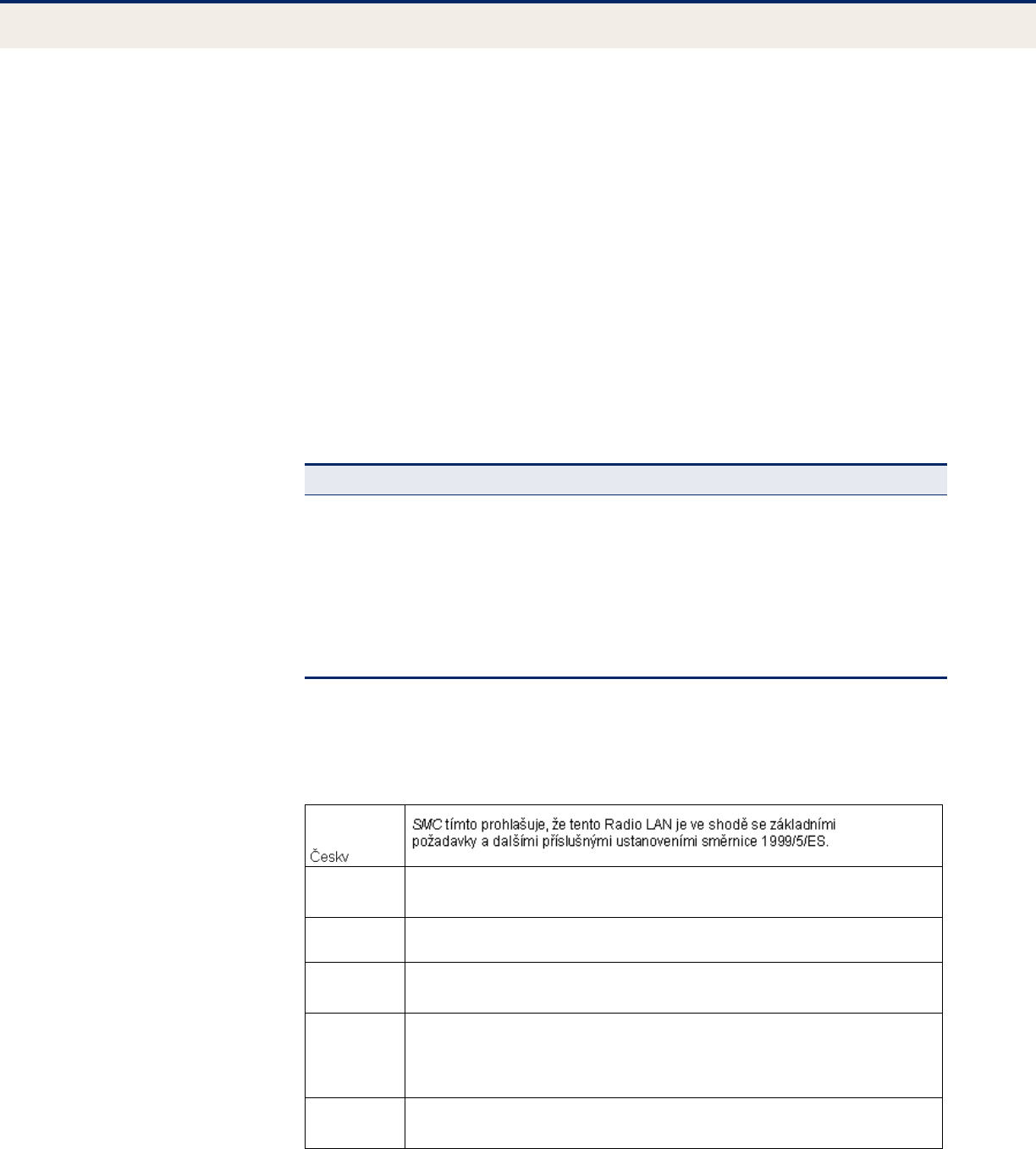
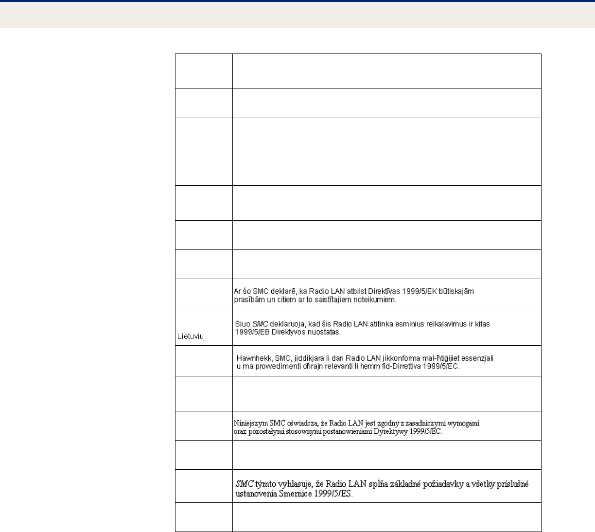
DECLARATION OF CONFORMITY IN LANGUAGES OF THE EUROPEAN
COMMUNITY
Allowed Frequency Bands Allowed Channel Numbers Countries
5.15 - 5.25 GHz* 36, 40, 44, 48 Austria, Belgium
5.15 - 5.35 GHz* 36, 40, 44, 48, 52, 56, 60, 64 France, Switzerland,
Liechtenstein
5.15 - 5.35* & 5.470 - 5.725 GHz 36, 40, 44, 48, 52, 56, 60, 64, 100,
104, 108, 112, 116, 120, 124, 128,
132, 136, 140
Denmark, Finland, Germany,
Iceland, Ireland, Italy,
Luxembourg, Netherlands,
Norway, Portugal, Spain,
Sweden, U.K.
5 GHz Operation Not Allowed None Greece
* Outdoor operation is not allowed using 5.15-5.35 GHz bands (Channels 36 - 64).
Czech
Estonian
Eesti
Käesolevaga kinnitab SMC seadme Radio LAN vastavust direktiivi 1999/5/EÜ
põhinõuetele ja nimetatud direktiivist tulenevatele teistele asjakohastele sätetele.
English Hereby, SMC, declares that this Radio LAN device is in compliance with the essential
requirements and other relevant provisions of Directive 1999/5/EC.
Finnish
Suomi
Valmistaja SMC vakuuttaa täten että Radio LAN device tyyppinen laite on direktiivin 1999/
5/EY oleellisten vaatimusten ja sitä koskevien direktiivin muiden ehtojen mukainen.
Dutch
Nederlands
Hierbij verklaart SMC dat het toestel Radio LAN device in overeenstemming is met de
essentiële eisen en de andere relevante bepalingen van richtlijn 1999/5/EG
Bij deze SMC dat deze Radio LAN device voldoet aan de essentiële eisen en aan de
overige relevante bepalingen van Richtlijn 1999/5/EC.
French
Français
Par la présente SMC déclare que l'appareil Radio LAN device est conforme aux
exigences essentielles et aux autres dispositions pertinentes de la directive 1999/5/CE
A
BOUT
T
HIS
G
UIDE
– 12 –
Swedish
Svenska
Härmed intygar SMC att denna Radio LAN device står I överensstämmelse med de
väsentliga egenskapskrav och övriga relevanta bestämmelser som framgår av direktiv
1999/5/EG.
Danish
Dansk
Undertegnede SMC erklærer herved, at følgende udstyr Radio LAN device overholder de
væsentlige krav og øvrige relevante krav i direktiv 1999/5/EF
German
Deutsch
Hiermit erklärt SMC, dass sich dieser/diese/dieses Radio LAN device in
Übereinstimmung mit den grundlegenden Anforderungen und den anderen relevanten
Vorschriften der Richtlinie 1999/5/EG befindet". (BMWi)
Hiermit erklärt SMC die Übereinstimmung des Gerätes Radio LAN device mit den
grundlegenden Anforderungen und den anderen relevanten Festlegungen der Richtlinie
1999/5/EG. (Wien)
Greek
ελληνικά
Με την παρουσα SMC δηλωνει οτι radio LAN device συμμορφωνεται προσ τισ ουσιωδεισ
απαιτησεισ και τισ λοιπεσ σΧετικεσ διαταξεισ τησ οδηγιασ 1999/5/εκ
Hungarian
Magyar
Alulírott, SMC nyilatkozom, hogy a Radio LAN megfelel a vonatkozó alapvetõ
követelményeknek és az 1999/5/EC irányelv egyéb elõírásainak.
Italian
Italiano
Con la presente SMC dichiara che questo Radio LAN device è conforme ai requisiti
essenziali ed alle altre disposizioni pertinenti stabilite dalla direttiva 1999/5/CE.
Latvian
Latviski
Lithuanian
Maltese
Malti
Spanish
Español
Por medio de la presente SMC declara que el Radio LAN device cumple con los requisitos
esenciales y cualesquiera otras disposiciones aplicables o exigibles de la Directiva 1999/
5/CE
Polish
Polski
Portuguese
Português
SMC declara que este Radio LAN device está conforme com os requisitos essenciais e
outras disposições da Directiva 1999/5/CE.
Slovak
Slovensky
Slovenian
Slovensko
SMC izjavlja, da je ta Radio LAN v skladu z bistvenimi zahtevami in ostalimi relevantnimi
doloili direktive 1999/5/ES.

– 13 –
ABOUT THIS GUIDE
PURPOSE This guide gives specific information on how to install the 11n wireless
access point and its physical and performance related characteristics. It
also gives information on how to operate and use the management
functions of the access point.
AUDIENCE This guide is intended for use by network administrators who are
responsible for installing, operating, and maintaining network equipment;
consequently, it assumes a basic working knowledge of LANs (Local Area
Networks), the Internet Protocol (IP), and Simple Network Management
Protocol (SNMP).
CONVENTIONS The following conventions are used throughout this guide to show
information:
N
OTE
:
Emphasizes important information or calls your attention to related
features or instructions.
C
AUTION
:
Alerts you to a potential hazard that could cause loss of data, or
damage the system or equipment.
W
ARNING
:
Alerts you to a potential hazard that could cause personal injury.
RELATED PUBLICATIONS As part of the access point’s software, there is an online web-based help
that describes all management related features.
REVISION HISTORY This section summarizes the changes in each revision of this guide.
MARCH 2009 REVISION
This is the first revision of this guide.

– 14 –
CONTENTS
LIMITED WARRANTY 4
COMPLIANCES 7
ABOUT THIS GUIDE 13
CONTENTS 14
FIGURES 19
TABLES 21
INDEX OF CLI COMMANDS 23
SECTION I GETTING STARTED 26
1INTRODUCTION 27
Key Hardware Features 27
Description of Capabilities 27
Package Contents 28
Hardware Description 29
Antennas 30
External Antenna Connector 30
LED Indicators 32
Console Port 33
Ethernet Port 33
Power Connector 33
Reset Button 34
2NETWORK TOPOLOGIES 35
Interference Issues 35
Infrastructure Wireless LAN 35
Infrastructure Wireless LAN for Roaming Wireless PCs 36
Infrastructure Wireless Bridge 37

C
ONTENTS
– 15 –
3INSTALLING THE ACCESS POINT 39
Location Selection 39
Mounting on a Horizontal Surface 40
Mounting on a Wall 41
Connecting and Powering On 42
4INITIAL CONFIGURATION 43
Connecting to the Login Page 43
Home Page and Main Menu 44
Common Web Page Buttons 45
Quick Start 46
Step 1 46
Step 2 47
Step 3 49
Main Menu Items 50
SECTION II WEB CONFIGURATION 51
5SYSTEM SETTINGS 52
Administration Settings 52
IP Address 54
Radius Settings 55
Primary and Secondary RADIUS Server Setup 56
RADIUS Accounting 58
System Time 58
SNTP Server Settings 59
Time Zone Setting 59
Daylight Saving Settings 60
SpectraLink Voice Priority 60
VLAN Configuration 60
System Logs 62
Quick Start Wizard 64
6MANAGEMENT SETTINGS 65
Remote Management Settings 65
Access Limitation 67
Simple Network Management Protocol 68

C
ONTENTS
– 16 –
SNMP Basic Settings 68
SNMP Trap Settings 70
View Access Control Model 71
SNMPv3 Users 73
SNMPv3 Targets 74
SNMPv3 Notification Filters 74
7ADVANCED SETTINGS 76
Local Bridge Filter 76
Link Layer Discovery Protocol 77
Access Control Lists 78
Source Address Settings 78
Destination Address Settings 79
Ethernet Type 80
8WIRELESS SETTINGS 82
Spanning Tree Protocol (STP) 82
Bridge 83
Ethernet Interface 84
Wireless Interface 85
Authentication 85
Local Authentication 85
RADIUS MAC Authentication 87
Interface Mode 88
Radio Settings 89
Virtual Access Points (VAPs) 93
VAP Basic Settings 94
WDS-STA Mode 95
Wireless Security Settings 95
Wired Equivalent Privacy (WEP) 97
QoS 99
9MAINTENANCE SETTINGS 103
Upgrading Firmware 103
Running Configuration 106
Resetting the Access Point 107
10 STATUS INFORMATION 109
AP Status 109

C
ONTENTS
– 17 –
AP System Configuration 109
AP Wireless Configuration 111
Station Status 112
System Logs 112
SECTION III COMMAND LINE INTERFACE 114
11 USING THE COMMAND LINE INTERFACE 116
Console Connection 116
Telnet Connection 117
Entering Commands 118
Keywords and Arguments 118
Minimum Abbreviation 118
Command Completion 118
Getting Help on Commands 118
Showing Commands 118
Negating the Effect of Commands 119
Using Command History 119
Understanding Command Modes 119
Exec Commands 120
Configuration Commands 120
Command Line Processing 121
12 GENERAL COMMANDS 122
13 SYSTEM MANAGEMENT COMMANDS 127
System Management Commands 127
14 SYSTEM LOGGING COMMANDS 143
15 SYSTEM CLOCK COMMANDS 148
16 DHCP RELAY COMMANDS 152
17 SNMP COMMANDS 154
18 FLASH/FILE COMMANDS 167
19 RADIUS CLIENT COMMANDS 170
20 802.1X AUTHENTICATION COMMANDS 175

C
ONTENTS
– 18 –
21 MAC ADDRESS AUTHENTICATION COMMANDS 177
22 FILTERING COMMANDS 181
23 SPANNING TREE COMMANDS 186
24 WDS BRIDGE COMMANDS 193
25 ETHERNET INTERFACE COMMANDS 195
26 WIRELESS INTERFACE COMMANDS 201
27 WIRELESS SECURITY COMMANDS 218
28 LINK LAYER DISCOVERY COMMANDS 228
29 VLAN COMMANDS 232
30 WMM COMMANDS 235
SECTION IV APPENDICES 240
ATROUBLESHOOTING 241
Diagnosing LED Indicators 241
Before Contacting Technical Support 241
BHARDWARE SPECIFICATIONS 244
CC
ABLES AND PINOUTS 247
Twisted-Pair Cable Assignments 247
10/100BASE-TX Pin Assignments 248
Straight-Through Wiring 248
Crossover Wiring 249
1000BASE-T Pin Assignments 250
Cable Testing for Existing Category 5 Cable 250
Adjusting Existing Category 5 Cabling to Run 1000BASE-T 250
Console Port Pin Assignments 251
GLOSSARY 252
INDEX 256

– 19 –
FIGURES
Figure 1: Top Panel 29
Figure 2: Rear Panel 29
Figure 3: Ports 30
Figure 4: External Antenna Connector 31
Figure 5: Screw-off External Antenna Connector - Close Up 31
Figure 6: LEDs 32
Figure 7: Infrastructure Wireless LAN 36
Figure 8: Infrastructure Wireless LAN for Roaming Wireless PCs 37
Figure 9: Bridging Mode 38
Figure 10: Attach Feet 40
Figure 11: Wall Mounting 41
Figure 12: Login Page 43
Figure 13: Home Page 44
Figure 14: Set Configuration Changes 45
Figure 15: Help Menu 45
Figure 16: Quick Start - Step 1 46
Figure 17: Quick Start - Step 2 47
Figure 18: Quick Start - Step 3 49
Figure 19: Administration 53
Figure 20: Set DNS Address 54
Figure 21: TCP/IP Settings 54
Figure 22: Invalid DNS 55
Figure 23: RADIUS Settings 57
Figure 24: SNTP Settings 59
Figure 25: SVP Settings 60
Figure 26: Setting the VLAN Identity 62
Figure 27: System Log Settings 63
Figure 28: Remote Management 66
Figure 29: Access Limitation 67
Figure 30: SNMP Basic Settings 69
Figure 31: SNMP Trap Settings 70

F
IGURES
– 20 –
Figure 32: SNMP VACM 71
Figure 33: Configuring SNMPv3 Users 73
Figure 34: SNMPv3 Targets 74
Figure 35: SNMP Notification Filter 75
Figure 36: Local Bridge Filter 76
Figure 37: LLDP Settings 77
Figure 38: Source ACLs 79
Figure 39: Destination ACLs 79
Figure 40: Ethernet Type Filter 81
Figure 41: Spanning Tree Protocol 83
Figure 42: Local Authentication 86
Figure 43: RADIUS Authentication 87
Figure 44: Interface Mode 88
Figure 45: Radio Settings 90
Figure 46: VAP Settings 93
Figure 47: VAP Basic Settings 94
Figure 48: WDS-STA Mode 95
Figure 49: Configuring VAPs - Common Settings 96
Figure 50: WEP Configuration 98
Figure 51: WMM Backoff Wait Times 100
Figure 52: QoS 101
Figure 53: Firmware 104
Figure 54: Running Configuration File 106
Figure 55: Resetting the Access Point 107
Figure 56: AP System Configuration 110
Figure 57: AP Wireless Configuration 111
Figure 58: Station Status 112
Figure 59: System Logs 112
Figure 60: RJ-45 Connector 247
Figure 61: Straight Through Wiring 249
Figure 62: Crossover Wiring 249
Figure 63: DB-9 Connector 251

– 21 –
TABLES
Table 1: Key Hardware Features 27
Table 2: LED Behavior 32
Table 3: RADIUS Attributes 62
Table 4: Logging Levels 64
Table 5: WMM Access Categories 99
Table 6: Command Modes 120
Table 7: Keystroke Commands 121
Table 8: General Commands 122
Table 9: System Management Commands 127
Table 10: Country Codes 128
Table 11: System Management Commands 143
Table 12: Logging Levels 145
Table 13: System Clock Commands 148
Table 14: DHCP Relay Commands 152
Table 15: SNMP Commands 154
Table 16: Flash/File Commands 167
Table 17: RADIUS Client Commands 170
Table 18: 802.1x Authentication 175
Table 19: MAC Address Authentication 177
Table 20: Filtering Commands 181
Table 21: Spanning Tree Commands 186
Table 22: WDS Bridge Commands 193
Table 23: Ethernet Interface Commands 195
Table 24: Wireless Interface Commands 201
Table 25: Wireless Security Commands 218
Table 26: Link Layer Discovery Commands 228
Table 27: VLAN Commands 232
Table 28: WMM Commands 235
Table 29: AP Parameters 237
Table 30: BSS Parameters 237
Table 31: LED Indicators 241


– 23 –
INDEX OF CLI COMMANDS
802.1x enable 175
802.1x session-timeout 176
address filter default 177
address filter delete 178
address filter entry 178
a-mpdu 203
a-msdu 203
APmgmtIP 135
APmgmtUI 136
assoc-timeout-interval 214
auth 218
auth-timeout-value 214
beacon-interval 210
bridge stp br-conf forwarding-delay
187
bridge stp br-conf hello-time 187
bridge stp br-conf interface 189
bridge stp br-conf max-age 188
bridge stp br-conf priority 188
bridge stp service 186
bridge-link path-cost 198
bridge-link port-priority 199
channel 204
cipher-suite 222
cli-session-timeout 123
closed-system 213
configure 122
copy 168
country 128
description 212
dhcp-relay 153
dhcp-relay enable 152
dns server 196
dtim-period 210
dual-image 167
encryption 220
end 123
exit 123
filter acl-destination-address enable
183
filter acl-destination-address mac-ad-
dress 183
filter acl-source-address enable 182
filter acl-source-address mac-address
183
filter ap-manage 182
filter ethernet-type enabled 184
filter ethernet-type protocol 184
filter local-bridge 181
interface ethernet 195
interface wireless 202
interface-radio-mode 205
ip address 196
ip dhcp 197
ip http port 133
ip http server 133
ip https port 134
ip https server 134
ip ssh-server enable 131
ip ssh-server port 132
ip telnet-server enable 132
key 221
lldp service 228
lldp transmit delay-to-local-change
230
lldp transmit interval 229
lldp transmit re-init-delay 229
lldp-transmit hold-muliplier 229
logging clear 146
logging console 144
logging facility-type 145
logging host 144
logging level 145
logging on 143
mac-authentication server 179
mac-authentication session-timeout
179
make-rf-setting-effective 207
make-security-effective 225
management-vlanid 233
password 131
ping 124
pmksa-lifetime 224
preamble 208
prompt 129
protection-method 209
radius-server accounting timeout-inter-
im 173
radius-server accounting key 173
radius-server accounting port 172
radius-server accounting-address 172
radius-server address 171
radius-server enable 170
radius-server key 171
radius-server port 171
reset 125
rts-threshold 211
short-guard-interval 209
show apmanagement 137
show authentication 176

I
NDEX
OF
CLI C
OMMANDS
– 24 –
show bridge br-conf 190
show bridge forward address 192
show bridge port-conf 190
show bridge status 192
show bridge stp 190
show config 138
show dhcp-relay 153
show dual-image 169
show event-log 147
show filters 185
show hardware 142
show history 125
show interface ethernet 200
show interface wireless 215
show line 126
show lldp 230
show logging 146
show radius 174
show snmp target 164
show snmp users 164
show snmp vacm group / show snmp
vacm view 165
show sntp 151
show station 217
show system 137
show version 138
show wds wireless 194
shutdown 198
shutdown 214
snmp-server community 154
snmp-server contact 155
snmp-server enable server 156
snmp-server filter 163
snmp-server host 157
snmp-server location 155
snmp-server targets 162
snmp-server trap 157
snmp-server user 161
snmp-server vacm group 160
snmp-server vacm view 159
sntp-server date-time 149
sntp-server daylight-saving 150
sntp-server enable 149
sntp-server ip 148
sntp-server timezone 150
ssid 212
system name 130
transmit-key 222
transmit-power 205
username 130
vap 203
vlan 232
vlan-id 234
wds ap 193
wds sta 193
wmm 235
wmm-acknowledge-policy 236
wmmparam 236
wpa-pre-shared-key 224

I
NDEX
OF
CLI C
OMMANDS
– 25 –

– 26 –
S
ECTION
I
GETTING STARTED
This section provides an overview of the access point, and introduces some
basic concepts about wireless networking. It also describes the basic
settings required to access the management interface.
This section includes these chapters:
◆“Introduction” on page 27
◆“Network Topologies” on page 35
◆“Installing the access point” on page 39
◆“Initial Configuration” on page 43

– 27 –
1INTRODUCTION
The EliteConnectTM SMCE21011 is an IEEE 802.11n access point (AP) that
meets draft 2.0 standards. It is fully interoperable with older 802.11a/b/g
standards, providing a transparent, wireless high speed data
communication between the wired LAN and fixed or mobile devices. The
unit includes three detachable dual-band 2.4/5 GHz antennas with the
option to attach higher specification external antennas that boost network
coverage.
KEY HARDWARE FEATURES
The following table describes the main hardware features of the AP.
DESCRIPTION OF CAPABILITIES
The SMC21011 supports up to eight Virtual Access Point (VAP) interfaces,
which allow traffic to be separated for different user groups within the
same AP service area. Each VAP can support up to 64 wireless clients,
whereby the clients associate with each VAP in the same way as they would
with physically separate access points. This means that each VAP can be
configured with its own Service Set Identification (SSID), security settings,
VLAN assignments, and other parameters, allowing the AP to serve a
diverse range of client needs in an area from a single unit.
Table 1: Key Hardware Features
Feature Description
Antennas Three detachable dual-band 2.4/5 GHz MIMO antennas.
LAN Port One 1000BASE-T RJ-45 port that supports a Power over Ethernet
(PoE) connection to power the device.
Console Port Console connection through an RJ-45 port with included RS-232
serial cable.
Reset Button For resetting the unit and restoring factory defaults.
LEDs Provides LED indicators for system status, wireless radio status,
and LAN port status.
Power Power over Ethernet (PoE) support through the RJ-45 Ethernet
port, or from an external AC power adapter.
Mounting Options Can be mounted on a wall, or on any horizontal surface such as a
desktop or shelf.

C
HAPTER
1
| Introduction
Package Contents
– 28 –
In addition, the access point offers full network management capabilities
through an easy to configure web interface, a command line interface for
initial configuration and troubleshooting, and support for Simple Network
Management tools.
The SMCE21011 utilises MIMO technology and Spatial Multiplexing to
achieve the highest possible data rate and throughput on the 802.11n
frequency. The unit’s PoE RJ-45 port provides a 1 Gbps full-duplex link to a
wired LAN.
PACKAGE CONTENTS
The EliteConnectTM SMCE21011 package includes:
◆11n Access Point (SMCE21011)
◆RJ-45 Category 5 network cable
◆RJ-45 to RS-232 console cable
◆AC power adapter
◆Four rubber feet
◆User Guide CD
Inform your dealer if there are any incorrect, missing or damaged parts. If
possible,retain the carton, including the original packing materials. Use
them again to repack the product in case there is a need to return it.
C
HAPTER
1
| Introduction
Hardware Description
– 29 –
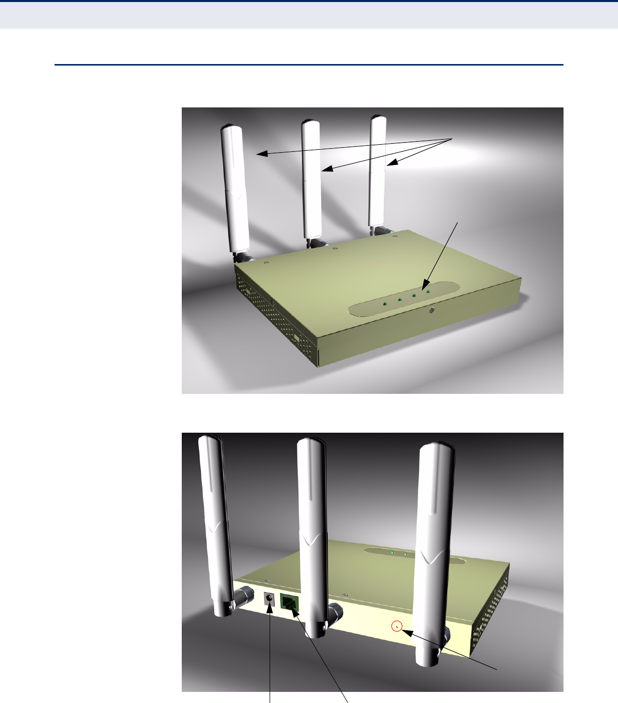
HARDWARE DESCRIPTION
Figure 1: Top Panel
Figure 2: Rear Panel
LED Indicators
Antennas
DC Power Port RJ-45 PoE Port
Reset Button

C
HAPTER
1
| Introduction
Hardware Description
– 30 –
Figure 3: Ports
ANTENNAS The access point includes three integrated external MIMO (multiple-input
and multiple-output) antennas. MIMO uses multiple antennas for
transmitting and receiving radio signals to improve data throughput and
link range.
Each antenna transmits the outgoing signal as a toroidal sphere (doughnut
shaped), with the coverage extending most in a direction perpendicular to
the antenna. Therefore, the antennas should be adjusted to an angle that
provides the appropriate coverage for the service area.
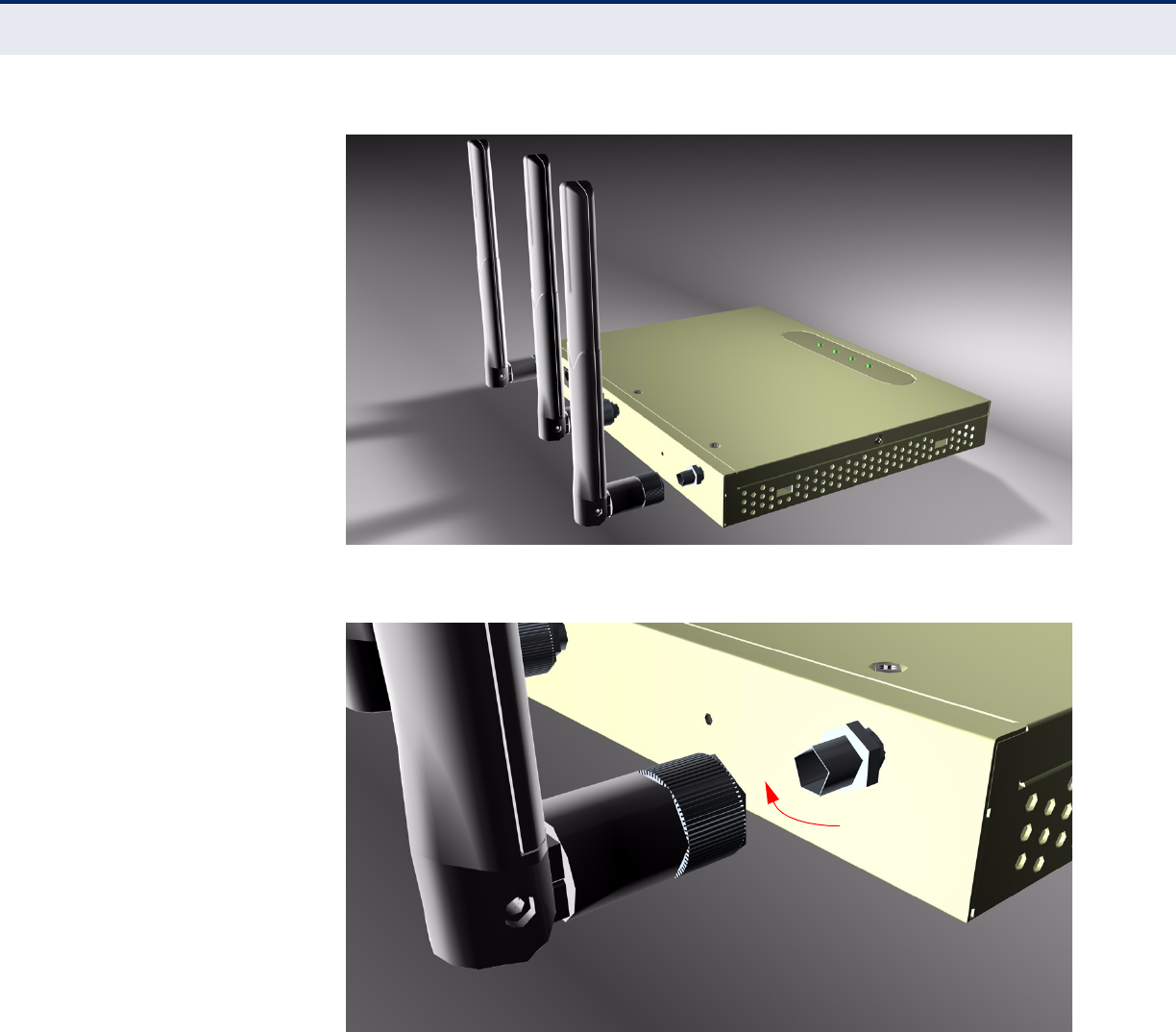
EXTERNAL ANTENNA
CONNECTOR
The access point supports external antennas for improving the coverage of
the 802.11n signal. The antennas supplied with the unit screw off in a
clockwise manner and can be replaced with with alternative antennas that
extend or shape the coverage area.
DC Power Port RJ-45 PoE Port RJ-45 Console Port
C
HAPTER
1
| Introduction
Hardware Description
– 31 –
Figure 4: External Antenna Connector
Figure 5: Screw-off External Antenna Connector - Close Up
C
HAPTER
1
| Introduction
Hardware Description
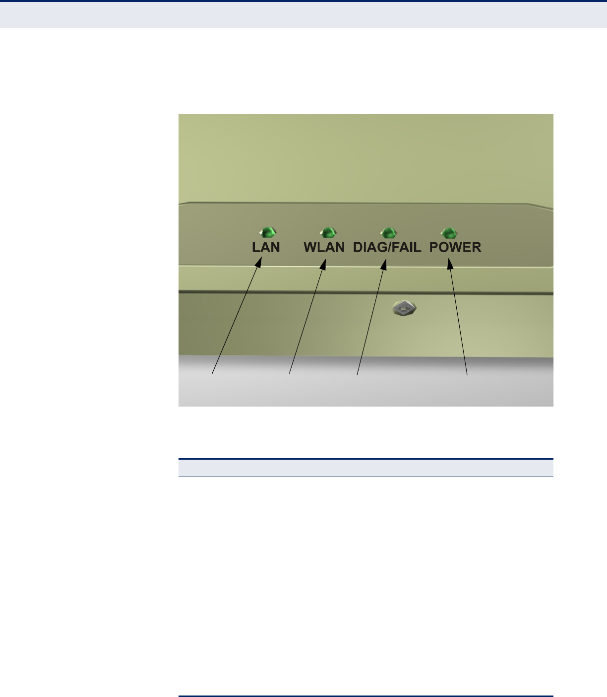
– 32 –
LED INDICATORS The access point includes four status LED indicators, as described in the
following figure and table.
Figure 6: LEDs
Table 2: LED Behavior
LED Status Description
LAN
(802.11a/n 5 GHz) Off The 802.11a/n radio is disabled.
Blue There is an 802.11n link.
Green There is an 802.11a link.
Flashing Indicates activity.
WLAN
(802.11b/g/n 2.4GHz) Off The 802.11b/g/n radio is disabled.
Blue There is an 802.11n link.
Green There is an 802.11b/g link.
Flashing Indicates activity.
DIAG/FAIL Off There is no connection on the LAN port.
Blue Indicates a 1000 Mbps link.
Green Indicates a 100 Mbps link.
Orange Indicates a 10 Mbps link.
Flashing Indicates activity.
802.11 b/g/n
Indicator Ethernet
Link/Activity Power
802.11 a/n
Indicator

C
HAPTER
1
| Introduction
Hardware Description
– 33 –
CONSOLE PORT This port is used to connect a console device to the access point through a
serial cable. The console device can be a PC or workstation running a VT-
100 terminal emulator, or a VT-100 terminal. A crossover RJ-45 to RS-232
cable is supplied with the unit for connecting to the console port.
ETHERNET PORT The access point has one 1000BASE-T RJ-45 port that can be attached
directly to 10BASE-T/100BASE-TX/1000BASE-TX LAN segments.
This port supports automatic MDI/MDI-X operation, so you can use
straight-through cables for all network connections to PCs, switches, or
hubs.
The access point appears as an Ethernet node and performs a bridging
function by moving packets from the wired LAN to remote workstations on
the wireless infrastructure.
N
OTE
:
The RJ-45 port also supports Power over Ethernet (PoE) based on
the IEEE 802.3af standard. Refer to the description for the “Power
Connector” for information on supplying power to the access point’s
network port from a network device, such as a switch or power injector,
that provides Power over Ethernet (PoE).
POWER CONNECTOR The access point does not have a power switch. It is powered on when
connected to the AC power adapter, and the power adapter is connected to
a power source. The power adapter automatically adjusts to any voltage
between 100~240 volts at 50 or 60 Hz, and supplies 48 volts DC power to
the unit. No voltage range settings are required.
The access point may also receive Power over Ethernet (PoE) from a switch
or other network device that supplies power over the network cable based
on the IEEE 802.3af standard.
POWER Off Indicates that there is no power or the power
source has been disconnected.
Flashing Green Indicates that the system is rebooting or has
started a reset.
Green Indicates that power is being supplied and the
system is functioning normally.
Red Indicates that there has been a system
malfunction.
Table 2: LED Behavior (Continued)
LED Status Description

C
HAPTER
1
| Introduction
Hardware Description
– 34 –
N
OTE
:
The access point supports both endspan and midspan PoE.
If the access point is connected to a PoE source device and also connected
to a local power source through the AC power adapter, AC power will be
disabled.
RESET BUTTON This button is used to reset the access point or restore the factory default
configuration. If you hold down the button for less than 5 seconds, the
access point will perform a hardware reset. If you hold down the button for
5 seconds or more, any configuration changes you may have made are
removed, and the factory default configuration is restored to the access
point.

– 35 –
2NETWORK TOPOLOGIES
Wireless networks support a standalone configuration as well as an
integrated configuration with 10/100/1000 Mbps Ethernet LANs. The
SMCE21011 also provides bridging services that can be configured
independently on either the 5 GHz or 2.4 GHz radio interfaces.
Access points can be deployed to support wireless clients and connect
wired LANs in the following configurations:
◆Infrastructure for wireless LANs
◆Infrastructure wireless LAN for roaming wireless PCs
◆Infrastructure wireless bridge to connect wired LANs
INTERFERENCE ISSUES
The 802.11b, 802.11g and 802.11n frequency band operating at 2.4 GHz
can easily encounter interference from other 2.4 GHz devices, such as
other 802.11b/g/n wireless devices, cordless phones and microwave
ovens. If you experience poor wireless LAN performance, try the following
measures:
◆Limit any possible sources of radio interference within the service area
◆Increase the distance between neighboring access points
◆Decrease the signal strength of neighboring access points
◆Increase the channel separation of neighboring access points (e.g. up
to 3 channels of separation for 802.11b, or up to 4 channels for
802.11a, or up to 5 channels for 802.11g)
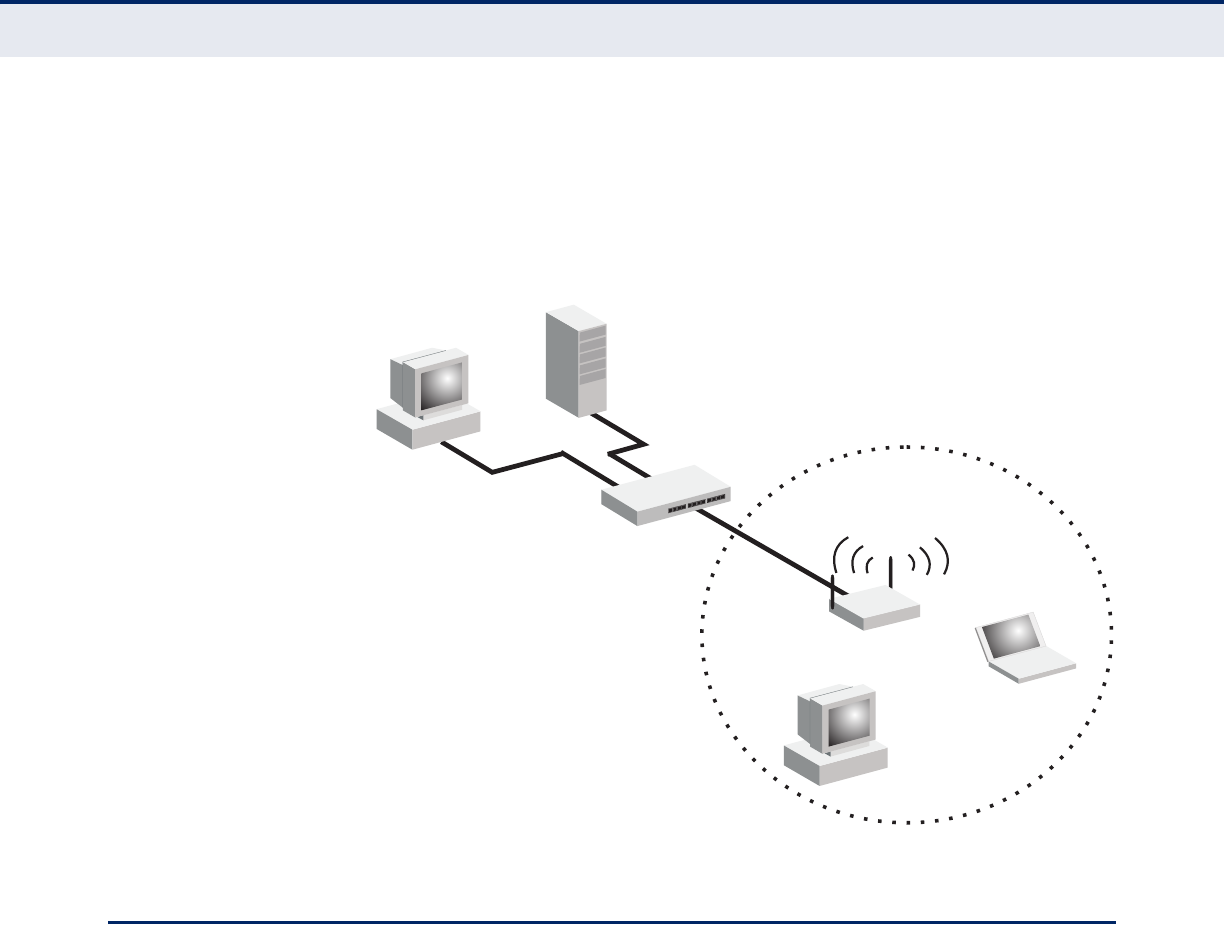
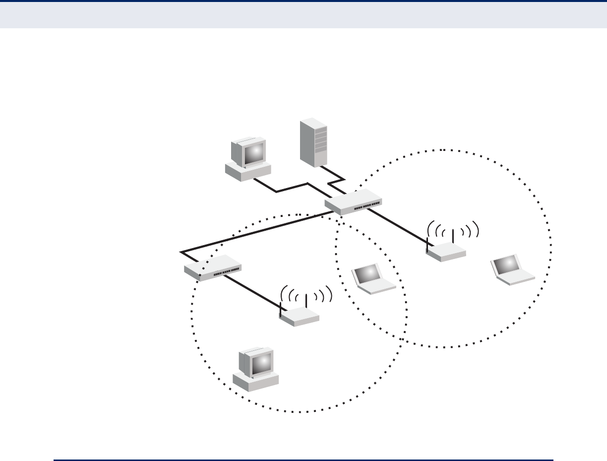
INFRASTRUCTURE WIRELESS LAN
The access point also provides access to a wired LAN for wireless
workstations. An integrated wired/wireless LAN is called an Infrastructure
configuration. A Basic Service Set (BSS) consists of a group of wireless PC
users, and an access point that is directly connected to the wired LAN.
Each wireless PC in this BSS can talk to any computer in its wireless group
via a radio link, or access other computers or network resources in the
wired LAN infrastructure via the access point.
C
HAPTER
2
| Network Topologies
Infrastructure Wireless LAN for Roaming Wireless PCs
– 36 –
The infrastructure configuration extends the accessibility of wireless PCs to
the wired LAN.
A wireless infrastructure can be used for access to a central database, or
for connection between mobile workers, as shown in the following figure.
Figure 7: Infrastructure Wireless LAN
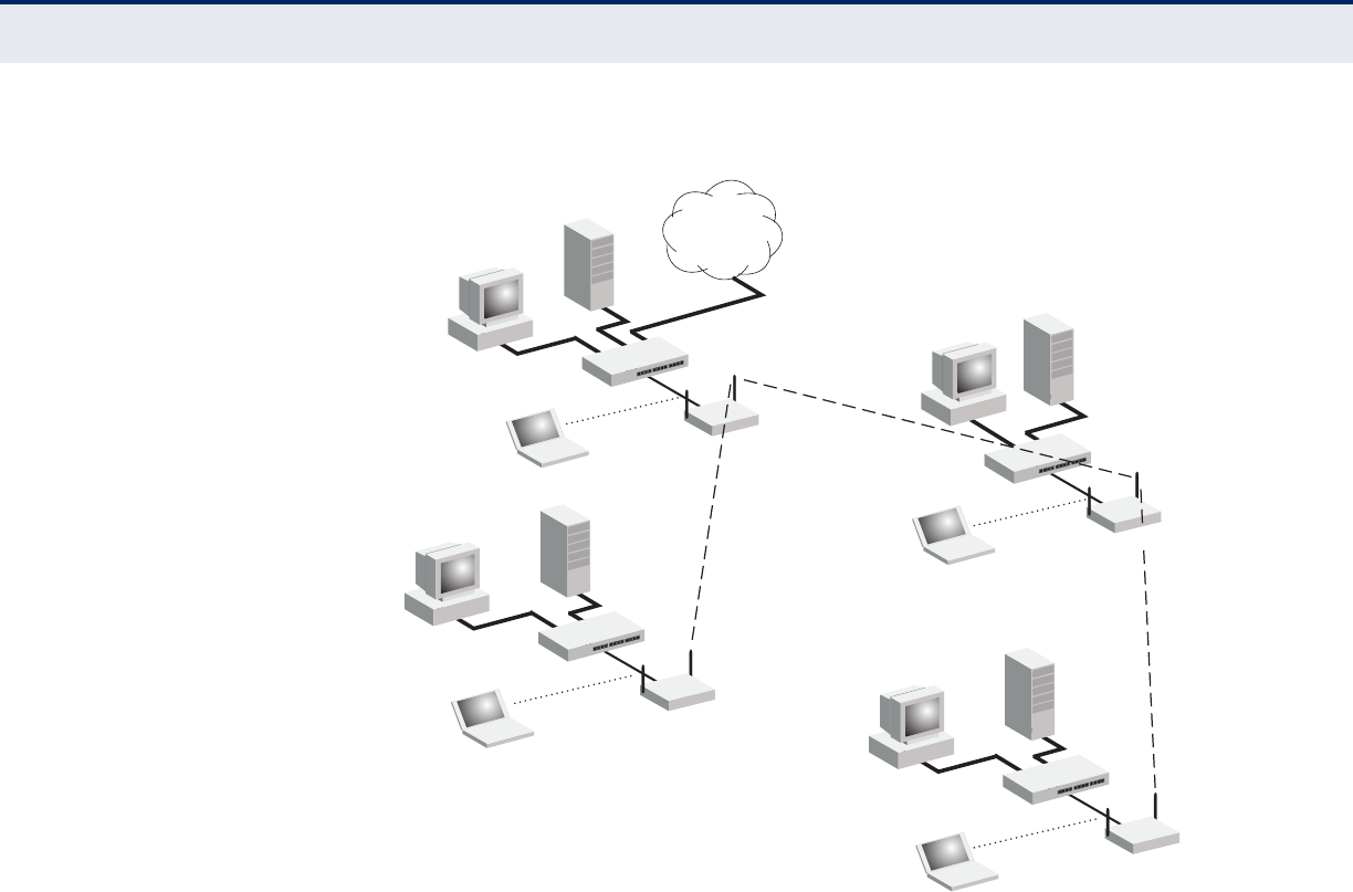
INFRASTRUCTURE WIRELESS LAN FOR ROAMING WIRELESS PCS
The Basic Service Set (BSS) defines the communications domain for each
access point and its associated wireless clients. The BSS ID is a 48-bit
binary number based on the access point’s wireless MAC address, and is
set automatically and transparently as clients associate with the access
point. The BSS ID is used in frames sent between the access point and its
clients to identify traffic in the service area.
The BSS ID is only set by the access point, never by its clients. The clients
only need to set the Service Set Identifier (SSID) that identifies the service
set provided by one or more access points. The SSID can be manually
configured by the clients, can be detected in an access point’s beacon, or
can be obtained by querying for the identity of the nearest access point.
For clients that do not need to roam, set the SSID for the wireless card to
that used by the access point to which you want to connect.
A wireless infrastructure can also support roaming for mobile workers.
More than one access point can be configured to create an Extended
Service Set (ESS). By placing the access points so that a continuous
Server
Switch
Desktop PC
Access Point
Wired LAN Extension
to Wireless Clients
Desktop PC
Notebook PC
C
HAPTER
2
| Network Topologies
Infrastructure Wireless Bridge
– 37 –
coverage area is created, wireless users within this ESS can roam freely. All
wireless network cards and adapters and wireless access points within a
specific ESS must be configured with the same SSID.
Figure 8: Infrastructure Wireless LAN for Roaming Wireless PCs
INFRASTRUCTURE WIRELESS BRIDGE
The IEEE 802.11 standard defines a Wireless Distribution System (WDS)
for bridge connections between BSS areas (access points). The access
point uses WDS to forward traffic on links between units.
The access point supports WDS bridge links that are independently
configurable on each VAP. There are two WDS modes; WDS-AP and WDS-
STA. Otherwise, VAPs operate in a normal AP mode.
◆AP Mode: Provides services to clients as a normal access point.
◆WDS-AP Mode: Operates as an access point in WDS mode, which
accepts connections from client stations in WDS mode.
◆WDS-STA Mode: Operates as a client station in WDS mode, which
connects to an access point in WDS mode. The user needs to specify
the MAC address of the access point in WDS mode to which it intends to
connect.
<BSS 2>
<ESS>
<BSS 1>
Server
Switch
Desktop PC
Access Point
Seamless Roaming
Between Access Points
Desktop PC
Notebook PC
Access Point
Notebook PC
Switch
C
HAPTER
2
| Network Topologies
Infrastructure Wireless Bridge
– 38 –
Figure 9: Bridging Mode
WDS Links
Between Access Points
VAP 2
WDS AP Mode
VAP 1
WDS AP Mode
VAP 2
WDS STA Mode
VAP 1
WDS AP Mode
VAP 1
WDS STA Mode
Network
Core
VAP 0
WDS AP Mode
VAP 1
WDS AP Mode
VAP 0
WDS STA Mode
VAP 0
WDS STA Mode
VAP 0
WDS STA Mode

– 39 –
3INSTALLING THE ACCESS POINT
This chapter describes how to install the access point.
LOCATION SELECTION
Choose a proper place for the access point. In general, the best location is
at the center of your wireless coverage area, within line of sight of all
wireless devices. Try to place the access point in a position that can best
cover its service area. For optimum performance, consider these
guidelines:
◆Mount the access point as high as possible above any obstructions in
the coverage area.
◆Avoid mounting next to or near building support columns or other
obstructions that may cause reduced signal or null zones in parts of the
coverage area.
◆Mount away from any signal absorbing or reflecting structures (such as
those containing metal).
The access point can be mounted on any horizontal surface, or a wall.
C
HAPTER
3
| Installing the access point
Mounting on a Horizontal Surface
– 40 –
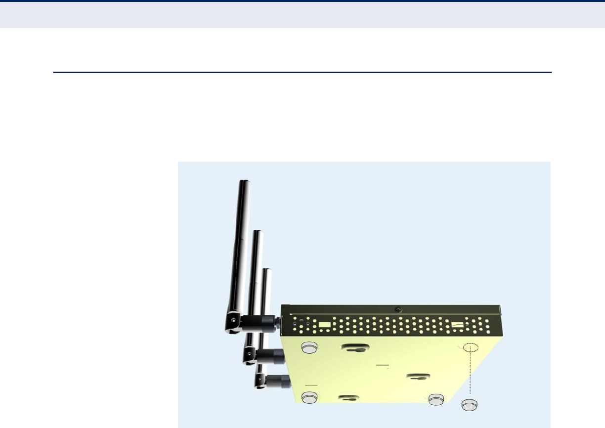
MOUNTING ON A HORIZONTAL SURFACE
To keep the access point from sliding on the surface, attach the four rubber
feet provided in the accessory kit to the marked circles on the bottom of
the access point.
Figure 10: Attach Feet
C
HAPTER
3
| Installing the access point
Mounting on a Wall
– 41 –
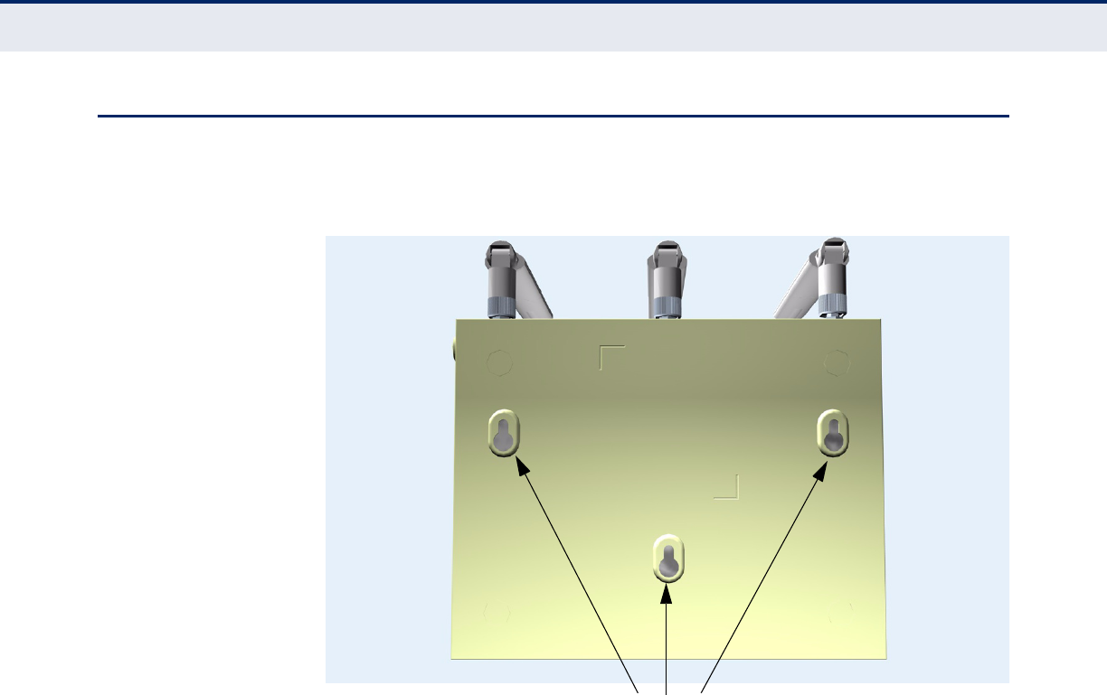
MOUNTING ON A WALL
To mount on a wall follow the instructions below.
Figure 11: Wall Mounting
The access point should be mounted only to a wall or wood surface that is
at least 1/2-inch plywood or its equivalent. To mount the access point on a
wall, always use its wall-mounting bracket. The access point must be
mounted with the RJ-45 cable connector oriented upwards to ensure
proper operation.
1. Mark the position of the three screw holes on the wall. For concrete or
brick walls, you will need to drill holes and insert wall plugs for the
screws.
2. Insert the included screws into the holes, leaving about 2-3 mm
clearance from the wall.
3. Line up the three mounting points on the AP with the screws in the wall,
then slide the AP down onto the screws until it is in a secured position.
Mounting Slots
C
HAPTER
3
| Installing the access point
Connecting and Powering On
– 42 –
CONNECTING AND POWERING ON
Connect the power adapter to the access point, and the power cord to an
AC power outlet.
Otherwise, the access point can derive its operating power directly from
the RJ-45 port when connected to a device that provides IEEE 802.3af
compliant Power over Ethernet (PoE).
C
AUTION
:
Use ONLY the power adapter supplied with this access point.
Otherwise, the product may be damaged.
N
OTE
:
If the access point is connected to both a PoE source device and an
AC power source, AC will be disabled.
1. Observe the Self Test – When you power on the access point, verify
that the Power indicator stops flashing and remains on, and that the
other indicators start functioning as described under “LED Indicators”
on page 32.
If the PWR LED does not stop flashing, the self test has not completed
correctly. Refer to “Troubleshooting” on page 241.
2. Connect the Ethernet Cable – The access point can be connected to
a 10/100/1000 Mbps Ethernet through a network device such as a hub
or a switch. Connect your network to the RJ-45 port on the back panel
with Category 5E or better UTP Ethernet cable. When the access point
and the connected device are powered on, the Ethernet Link LED
should light indicating a valid network connection.
N
OTE
:
The RJ-45 port on the access point supports automatic MDI/MDI-X
operation, so you can use straight-through cables for all network
connections to PCs, switches, or hubs.
3. Position the Antennas – Each antenna emits a radiation pattern that
is toroidal (doughnut shaped), with the coverage extending most in the
direction perpendicular to the antenna. Therefore, the antennas should
be oriented so that the radio coverage pattern fills the intended
horizontal space. Also, the antennas should both be positioned along
the same axes, providing the same coverage area. For example, if the
access point is mounted on a horizontal surface, all antennas should be
positioned pointing vertically up to provide optimum coverage.
4. Connect the Console Port – Connect the RJ-45 console cable
(included with access point) to the RS-232 console port for accessing
the command-line interface. You can manage the access point using
the console port, the web interface, or SNMP management software.

– 43 –
4INITIAL CONFIGURATION
The SMCE21011 offers a user-friendly web-based management interface
for the configuration of all the unit’s features. Any PC directly attached to
the unit can access the management interface using a web browser, such
as Internet Explorer (version 6.0 or above).
CONNECTING TO THE LOGIN PAGE
It is recommended to make initial configuration changes by connecting a
PC directly to the SMCE21011’s LAN port. The SMCE21011 has a default IP
address of 192.168.1.1 and a subnet mask of 255.255.255.0. You must set
your PC IP address to be on the same subnet as the SMCE21011 (that is,
the PC and SMCE21011 addresses must both start 192.168.1.x).
To access the access point management interface, follow these steps:
1. Use your web browser to connect to the management interface using
the default IP address of 192.168.1.1.
2. Log into the interface by entering the default username “accton” and
password also “accton,” then click Login.
N
OTE
:
It is strongly recommended to change the default user name and
password the first time you access the web interface. For information on
changing user names and passwords, See “Administration Settings” on
page 52.
Figure 12: Login Page
C
HAPTER
4
| Initial Configuration
Home Page and Main Menu
– 44 –
HOME PAGE AND MAIN MENU
After logging in to the web interface, the Home page displays. The Home
page shows some basic settings for the AP, including Country Code and the
management access password.
Figure 13: Home Page
The web interface Main Menu menu provides access to all the configuration
settings available for the access point.
The following items are displayed on this page:
◆System Name – An alias for the access point, enabling the device to
be uniquely identified on the network. (Default: 11n_AP; Range: 1-32
characters)
◆Username – The name of the user. The default name is “admin.”
(Length: 3-16 characters, case sensitive)
◆Old Password – Type your old password. The default password is
“smcdamin.”
◆New Password – The password for management access. (Length: 3-
16 characters, case sensitive)
◆Confirm New Password – Enter the password again for verification.
◆Country Code – This command configures the access point’s country
code, which identifies the country of operation and sets the authorized
radio channels.
C
HAPTER
4
| Initial Configuration
Common Web Page Buttons
– 45 –
C
AUTION
:
You must set the country code to the country of operation.
Setting the country code restricts operation of the access point to the radio
channels and transmit power levels permitted for wireless networks in the
specified country.
COMMON WEB PAGE BUTTONS
The list below describes the common buttons found on most web
management pages:
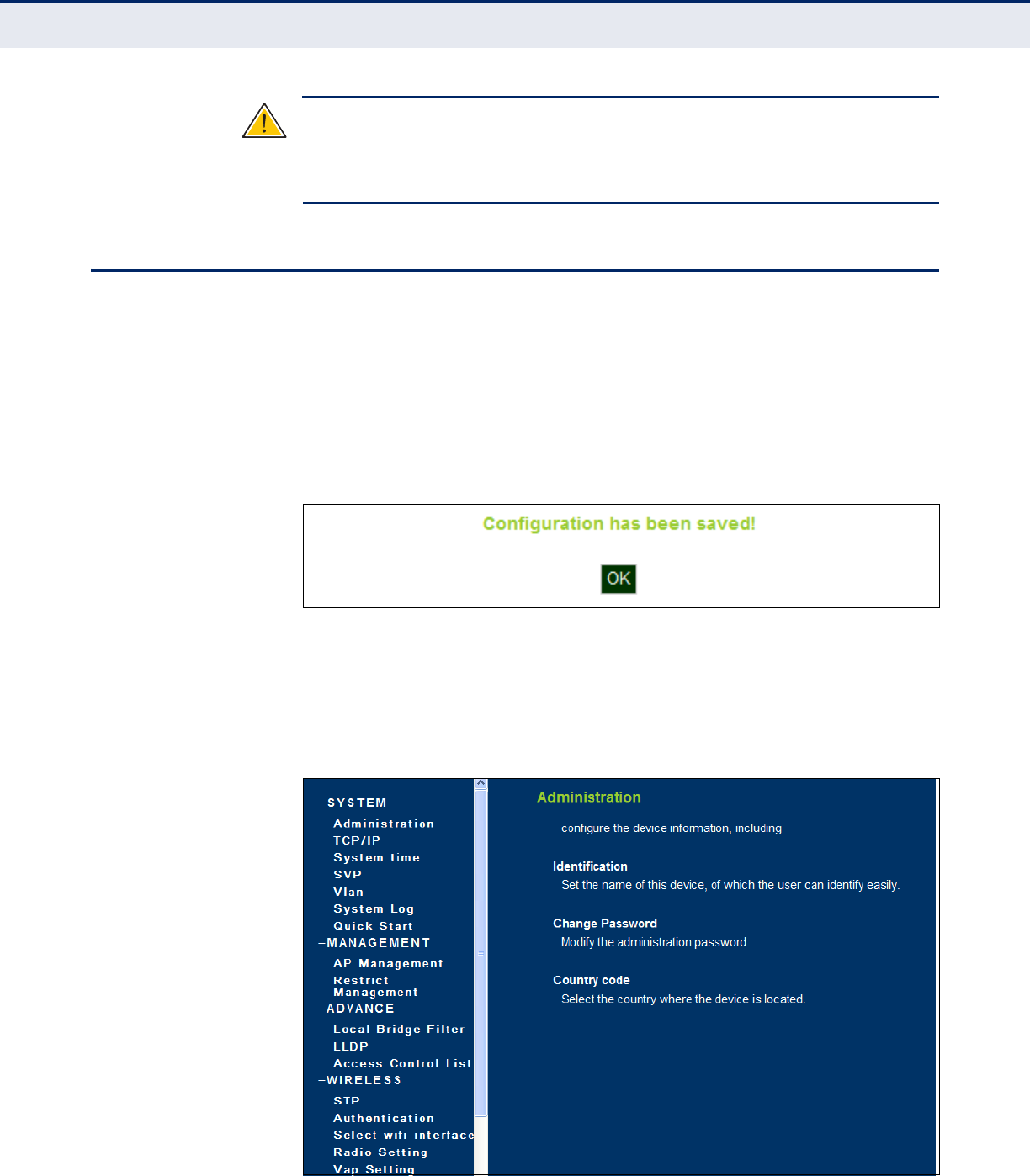
◆Set – Applies the new parameters and saves them to temporary RAM
memory. Also displays a screen to inform you when it has taken affect.
Clicking ‘OK’ returns to the home page. The running configuration will
not be saved upon a reboot unless you use the “Save Config” button.
Figure 14: Set Configuration Changes
◆Cancel – Cancels the newly entered settings and restores the originals.
◆Help – Displays the help window.
Figure 15: Help Menu
C
HAPTER
4
| Initial Configuration
Quick Start
– 46 –
◆Logout – Ends the web management session.
◆Save Config – Saves the current configuration so that it is retained
after a restart.
QUICK START
The Quick Start menu is designed to help you configure the basic settings
required to get the access point up and running. Click ‘System’, followed by
‘Quick Start’.
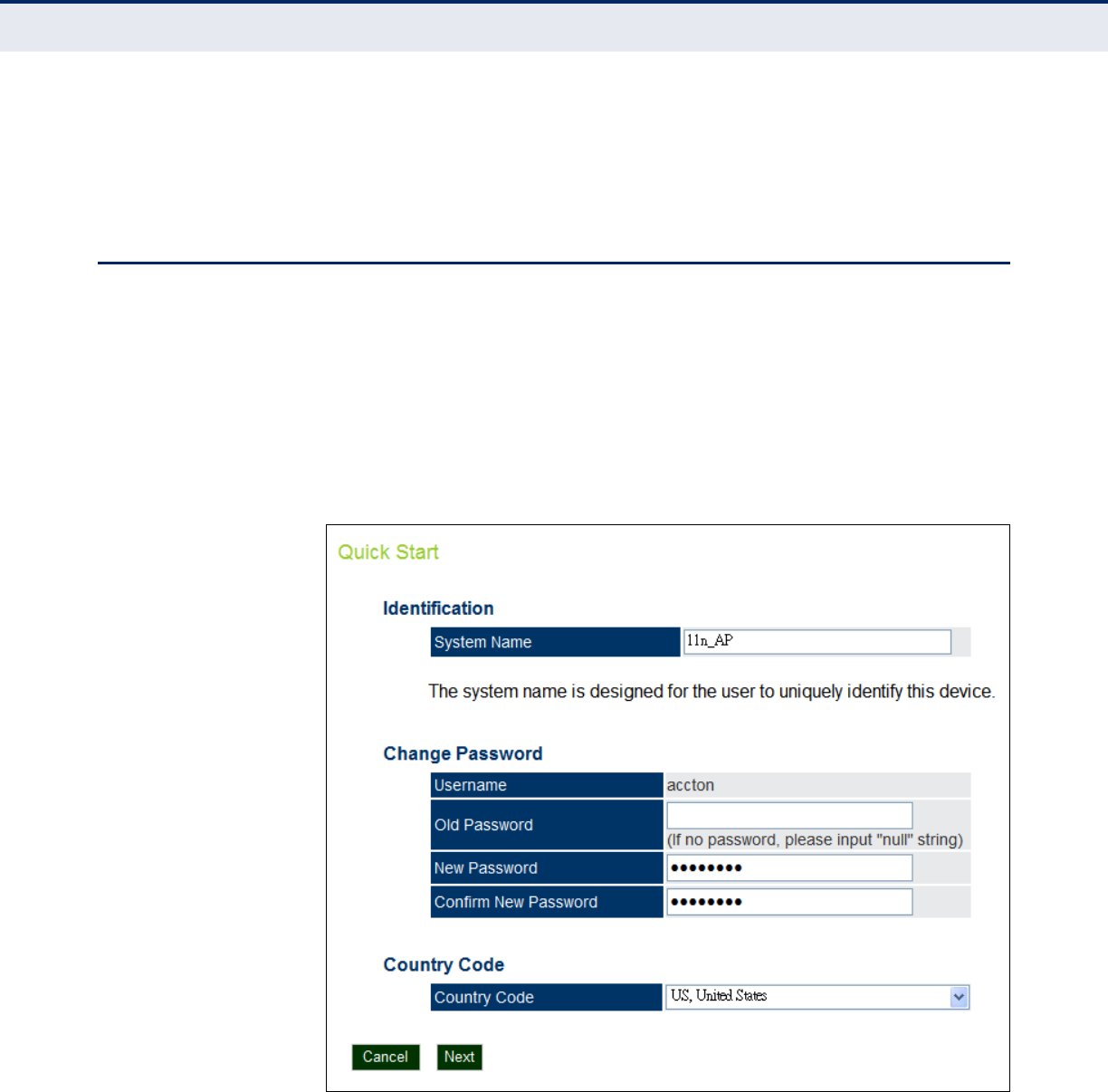
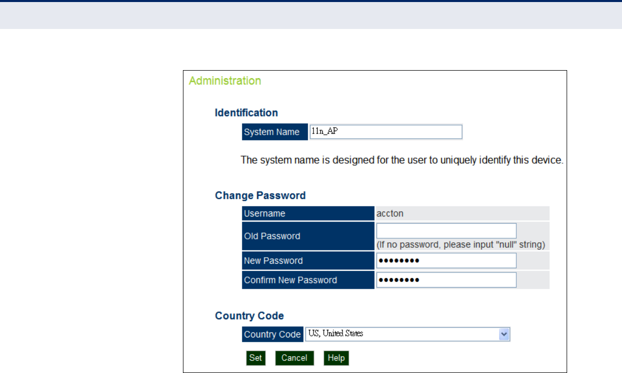
STEP 1 The first page of the Quick Start configures the system identification,
access password, and the Country Code.
Figure 16: Quick Start - Step 1
The following items are displayed on the first page of the Quick Start
wizard:
IDENTIFICATION
◆System Name — The name assigned to the access point.
(Default: 11n_AP)
C
HAPTER
4
| Initial Configuration
Quick Start
– 47 –
CHANGE PASSWORD
◆Username — The name of the user, non-configurable.
(Default: accton)
◆Old Password — If the unit has been configured with a password
already, enter that password, otherwise enter a null string.
◆New Password — The password for management access.
(Length: 3-16 characters, case sensitive)
◆Confirm New Password — Enter the password again for verification.
COUNTRY CODE
◆Country Code — Configures the access point’s country code from a
drop down menu, which identifies the country of operation and sets the
authorized radio channels.
C
AUTION
:
You must set the country code to the country of operation.
Setting the country code restricts operation of the access point to the radio
channels and transmit power levels permitted for wireless networks in the
specified country.
◆Cancel — Cancels the newly entered settings and restores the orignals.
◆Next — Proceeds to the next page.
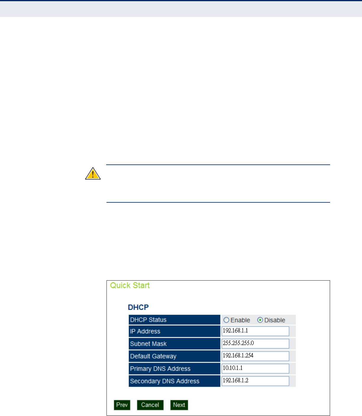
STEP 2 The Step 2 page of the Quick Start configures IP settings and DHCP client
status.
Figure 17: Quick Start - Step 2

C
HAPTER
4
| Initial Configuration
Quick Start
– 48 –
The following items are displayed on this page:
DHCP
◆DHCP Status — Enables/disables DHCP on the access point. (Default:
disabled)
◆IP Address — Specifies an IP address for management of the access
point. Valid IP addresses consist of four decimal numbers, 0 to 255,
separated by periods. (Default: 192.168.1.1.)
◆Subnet Mask — Indicates the local subnet mask. Select the desired
mask from the drop down menu. (Default: 255.255.255.0)
◆Default Gateway — The default gateway is the IP address of the
router for the access point, which is used if the requested destination
address is not on the local subnet. (Default: 192.168.1.254)
If you have management stations, DNS, RADIUS, or other network
servers located on another subnet, type the IP address of the default
gateway router in the text field provided.
◆Primary and Secondary DNS Address — The IP address of Domain
Name Servers on the network. A DNS maps numerical IP addresses to
domain names and can be used to identify network hosts by familiar
names instead of the IP addresses. (Primary DNS Default Address:
10.10.1.1; Secondary DNS Default Address: 192.168.1.2)
◆Prev — Returns to the previous screen.
◆Cancel — Cancels the newly entered settings and restores the orignals.
◆Next — Proceeds to the final step in the Quick Start wizard.
C
HAPTER
4
| Initial Configuration
Quick Start
– 49 –
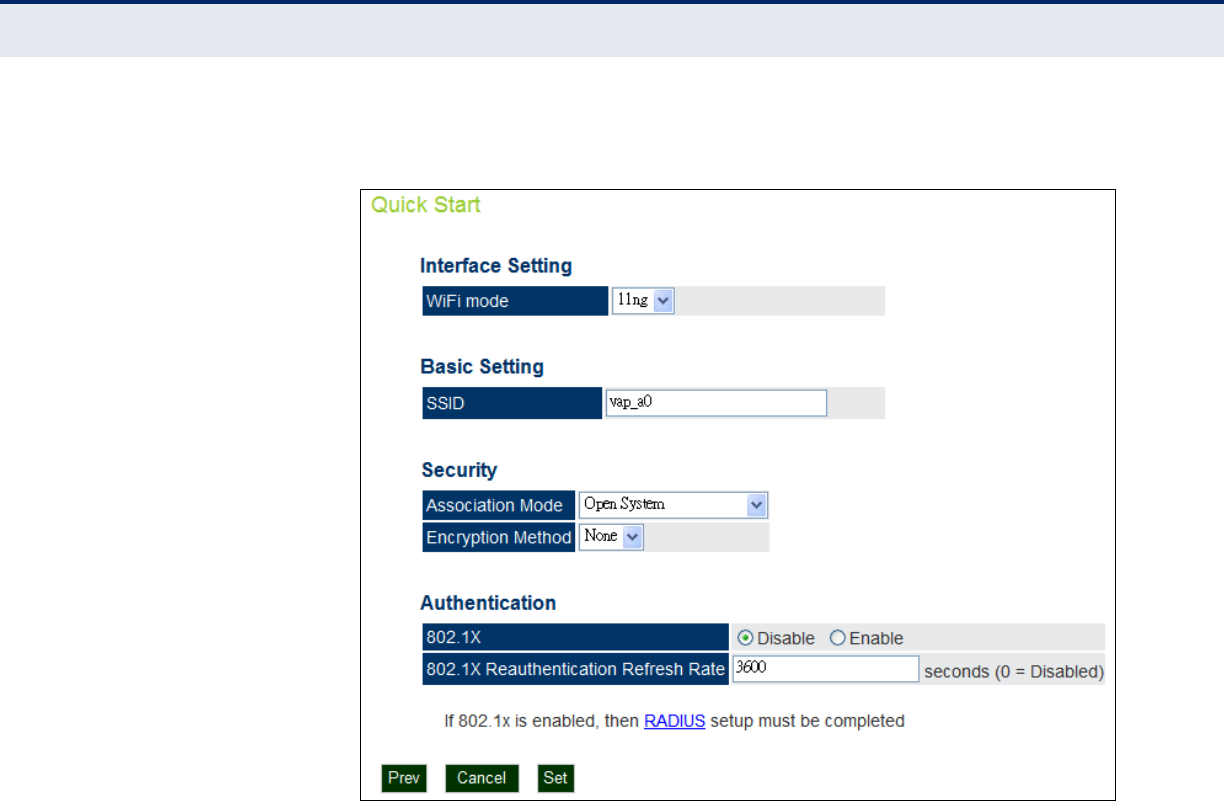
STEP 3 The Step 3 page of the Quick Start configures radio interface settings.
Figure 18: Quick Start - Step 3
The following items are displayed on this page:
INTERFACE SETTING
◆WiFi Mode — Selects mode of operation of the radio chip from
802.11n/g compliant or 802.11n/a compliant. (Default: 11n/g)
BASIC SETTING
◆SSID — Sets the service set identifyer for the primary VAP.
(Default: vap_a0)
SECURITY
◆Association Mode — Selects the security mode for association of
other access points and wireless devices to the access point.
(Default: Open System; Range: Open System, WPA, WPA-PSK, WPA2,
WPA2-PSK, WPA-WPA2-mixed, or WPA-WPA2-PSK-mixed)
◆Encryption Mode — If set to Open System the Encryption Method is
‘None’, or WEP Keys may be enabled

C
HAPTER
4
| Initial Configuration
Main Menu Items
– 50 –
AUTHENTICATION
◆802.1x — Enables 802.1x authentication. (Default: Enabled)
◆802.1x Reauthentication Refresh Rate — Sets the reauthentication
refresh rate for 802.1x authentication. (Default: 3600 seconds; Range:
1-65535 seconds; 0=disabled)
◆RADIUS — If configuring a RADIUS server refer to the section
“RADIUS Client Commands” on page 170.
MAIN MENU ITEMS
To configure settings, click the relevant Main Menu item. Each Main Menu
item is sumarized below with links to the relevant section in this guide
where configuration parameters are described in detail:
◆System — Configures Management IP, WAN, LAN and QoS settings.
See “System Settings” on page 52.
◆Adminstration — Configures HTTP and Telnet settings. See
“Management Settings” on page 65
◆Advance — Confiures LLDP and Access Control Lists. See “Advanced
Settings” on page 76
◆Wireless Settings — Configures Wi-Fi access point settings. See
“Wireless Settings” on page 82.
◆SNMP — Configures SNMP settings. See “SNMP Services” on page 92
◆Mantentance — Congifures firmware upgrades remote and locally. See
“Maintenance Settings” on page 103
◆Information — Displays current system settings. See “Status
Information” on page 109.

– 51 –
S
ECTION
II
WEB CONFIGURATION
This section provides details on configuring the access point using the web
browser interface.
This section includes these chapters:
◆“System Settings” on page 52
◆“Management Settings” on page 65
◆“Advanced Settings” on page 76
◆“Wireless Settings” on page 82
◆“SNMP Services” on page 92
◆“Maintenance Settings” on page 103
◆“Status Information” on page 109

– 52 –
5SYSTEM SETTINGS
This chapter describes basic system settings on the access point. It
includes the following sections:
◆“Administration Settings” on page 52
◆“IP Address” on page 54
◆“Radius Settings” on page 55
◆“System Time” on page 58
◆“SpectraLink Voice Priority” on page 60
◆“VLAN Configuration” on page 60
◆“System Logs” on page 62
◆“Quick Start Wizard” on page 64
ADMINISTRATION SETTINGS
The access point can be managed by any computer using a web browser
(Internet Explorer 5.0 or above, or Firefox 2.0 or above). Enter the
configured IP address of the access point, or use the default address:
http://192.168.1.1
To log into the access point, enter the default user name “accton” and the
password “accton”, then click “LOGIN”. When the home page displays, click
on Advanced Setup. The following page will display.
C
HAPTER
5
| System Settings
Administration Settings
– 53 –
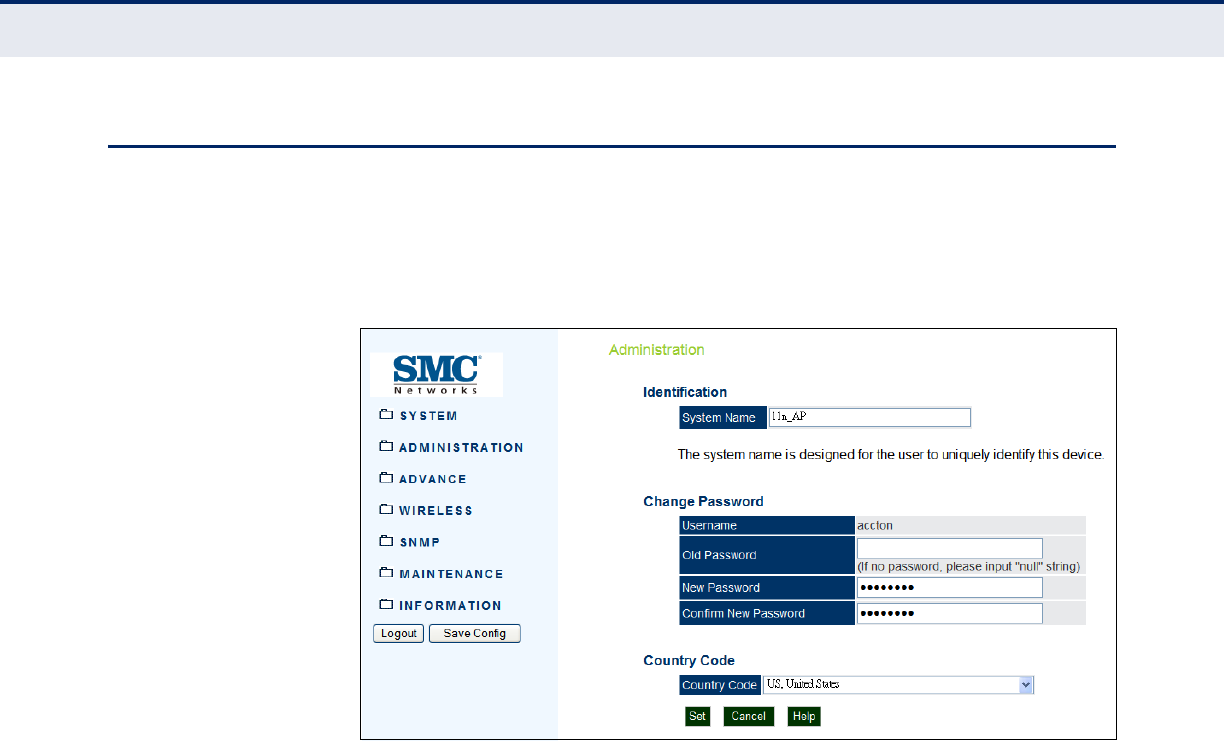
Figure 19: Administration
The following items are displayed on this page:
◆System Name — An alias for the access point, enabling the device to
be uniquely identified on the network. (Default: SMC; Range: 1-32
characters)
◆Username — The name of the user. The default name is “admin.”
(Length: 3-16 characters, case sensitive)
◆Old Password — Type your old password.
◆New Password — The password for management access. (Length: 3-
16 characters, case sensitive)
◆Confirm New Password — Enter the password again for verification.
◆Country Code — This command configures the access point’s country
code, which identifies the country of operation and sets the authorized
radio channels.
C
HAPTER
5
| System Settings
IP Address
– 54 –
IP ADDRESS
Configuring the access point with an IP address expands your ability to
manage the access point. A number of access point features depend on IP
addressing to operate.
You can use the web browser interface to access IP addressing only if the
access point already has an IP address that is reachable through your
network.
By default, the access point will be not be automatically configured with IP
settings from a Dynamic Host Configuration Protocol (DHCP) server. The
default IP address is 192.168.1.1, subnet mask 255.255.255.0 and a
default gateway of 192.168.1.254.
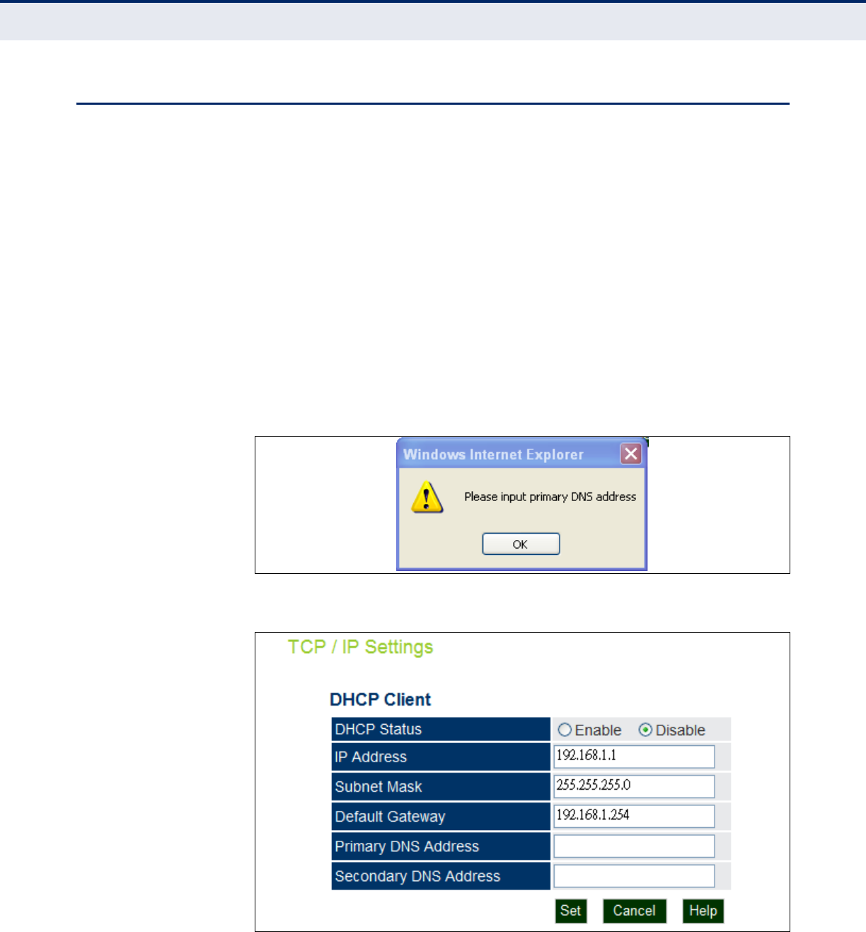
You will first be prompted to enter the primary and secondary DNS address
for the unit before having access to the other IP parameters.
Figure 20: Set DNS Address
Figure 21: TCP/IP Settings
The following items are displayed on this page:
C
HAPTER
5
| System Settings
Radius Settings
– 55 –
◆DHCP Status — Enables/disables DHCP on the access point.
◆IP Address — Specifies an IP address for management of the access
point. Valid IP addresses consist of four decimal numbers, 0 to 255,
separated by periods. (Default: 192.168.1.1.)
◆Subnet Mask — Indicates the local subnet mask. Select the desired
mask from the drop down menu. (Default: 255.255.255.0)
◆Default Gateway — The default gateway is the IP address of the
router for the access point, which is used if the requested destination
address is not on the local subnet.
If you have management stations, DNS, RADIUS, or other network
servers located on another subnet, type the IP address of the default
gateway router in the text field provided.
◆Primary and Secondary DNS Address — The IP address of Domain
Name Servers on the network. A DNS maps numerical IP addresses to
domain names and can be used to identify network hosts by familiar
names instead of the IP addresses.
If you have one or more DNS servers located on the local network, type
the IP addresses in the text fields provided.
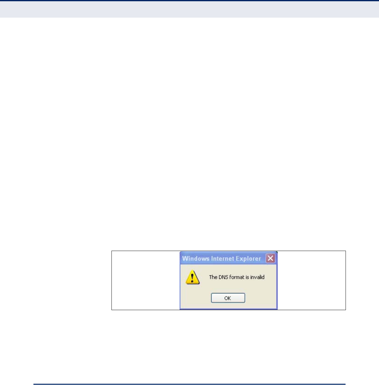
Make sure to type the correct DNS server address or the following
message will display.
Figure 22: Invalid DNS
After you have network access to the access point, you can use the web
browser interface to modify the initial IP configuration, if needed.
If there is no DHCP server on your network, or DHCP fails, the access point
will automatically start up with a default IP address of 192.168.1.1
RADIUS SETTINGS
Remote Authentication Dial-in User Service (RADIUS) is an authentication
protocol that uses software running on a central server to control access to
RADIUS-aware devices on the network. An authentication server contains a
database of user credentials for each user that requires access to the
network.

C
HAPTER
5
| System Settings
Radius Settings
– 56 –
PRIMARY AND
SECONDARY RADIUS
SERVER SETUP
A primary RADIUS server must be specified for the access point to
implement IEEE 802.1X network access control and Wi-Fi Protected Access
(WPA) wireless security. A secondary RADIUS server may also be specified
as a backup should the primary server fail or become inaccessible.
In addition, the configured RADIUS server can also act as a RADIUS
Accounting server and receive user-session accounting information from
the access point. RADIUS Accounting can be used to provide valuable
information on user activity in the network.
This guide assumes that you have already configured RADIUS server(s) to
support the access point. Configuration of RADIUS server software is
beyond the scope of this guide, refer to the documentation provided with
the RADIUS server software.
C
HAPTER
5
| System Settings
Radius Settings
– 57 –
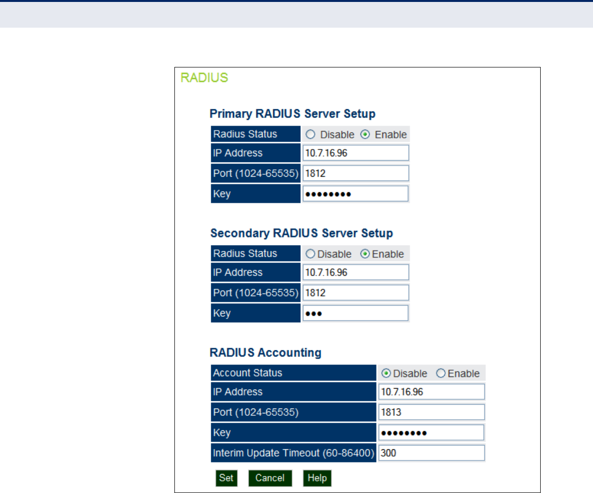
Figure 23: RADIUS Settings
The following items are displayed on the RADIUS Settings page:
◆RADIUS Status — Enables/disables the primary RADIUS server.
◆IP Address — Specifies the IP address or host name of the RADIUS
server.
◆Port (1024-65535) — The UDP port number used by the RADIUS
server for authentication messages. (Range: 1024-65535; Default:
1812)
◆Key — A shared text string used to encrypt messages between the
access point and the RADIUS server. Be sure that the same text string
is specified on the RADIUS server. Do not use blank spaces in the
string. (Maximum length: 255 characters)

C
HAPTER
5
| System Settings
System Time
– 58 –
RADIUS ACCOUNTING The following items are displayed on the RADIUS Settings page:
◆Account Status — Enables/disables RADIUS accounting.
◆IP Address — Specifies the IP address or host name of the RADIUS
accounting server.
◆Port (1024-65535) — The UDP port number used by the RADIUS
accounting server for authentication messages. (Range: 1024-65535;
Default: 1812)
◆Key — A shared text string used to encrypt messages between the
access point and the RADIUS accounting server. Be sure that the same
text string is specified on the RADIUS server. Do not use blank spaces
in the string. (Maximum length: 255 characters)
◆Interim Update Timeout (60-86400) — The interval between
transmitting accounting updates to the RADIUS server. (Range: 60-
86400; Default: 3600 seconds)
SYSTEM TIME
Simple Network Time Protocol (SNTP) allows the access point to set its
internal clock based on periodic updates from a time server (SNTP or NTP).
Maintaining an accurate time on the access point enables the system log to
record meaningful dates and times for event entries. If the clock is not set,
the access point will only record the time from the factory default set at the
last bootup.
The access point acts as an SNTP client, periodically sending time
synchronization requests to specific time servers. You can configure up to
two time server IP addresses. The access point will attempt to poll each
server in the configured sequence.
C
HAPTER
5
| System Settings
System Time
– 59 –
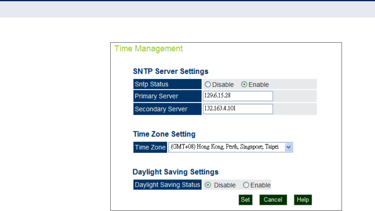
Figure 24: SNTP Settings
The following items are displayed on this page:
SNTP SERVER
SETTINGS
Configures the access point to operate as an SNTP client. When enabled, at
least one time server IP address must be specified.
◆SNTP Status — Enables/disables SNTP. (Default: enabled)
◆Primary Server — The IP address of an SNTP or NTP time server that
the access point attempts to poll for a time update.
◆Secondary Server — The IP address of a secondary SNTP or NTP time
server. The access point first attempts to update the time from the
primary server; if this fails it attempts an update from the secondary
server.
TIME ZONE SETTING SNTP uses Greenwich Mean Time, or GMT (sometimes referred to as
Coordinated Universal Time, or UTC) based on the time at the Earth’s
prime meridian, zero degrees longitude. To display a time corresponding to
your local time, you must indicate the number of hours your time zone is
located before (east) or after (west) GMT.
◆Time Zone — Select from the scroll down list the locale you are
situated most close to, for example for New York, select ‘(GMT-05)
Eastern Time (US & Canada)’.
C
HAPTER
5
| System Settings
SpectraLink Voice Priority
– 60 –
DAYLIGHT SAVING
SETTINGS
The access point provides a way to automatically adjust the system clock
for Daylight Savings Time changes. To use this feature you must define the
month and date to begin and to end the change from standard time.
During this period the system clock is set back by one hour.
◆Daylight Saving Status — Enalbes/disables daylight savings time.
(Default: disabled)
SPECTRALINK VOICE PRIORITY
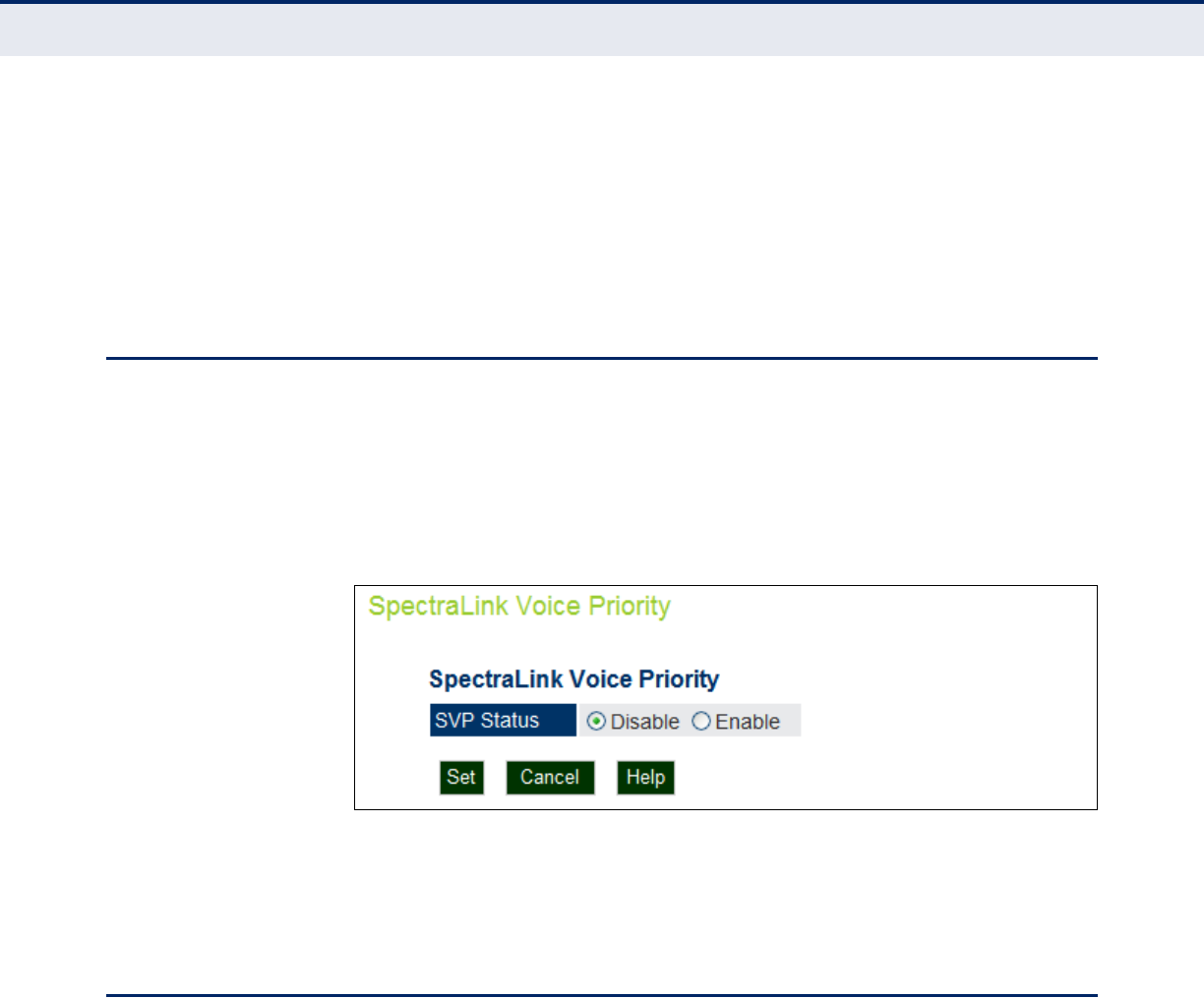
SpectraLink Voice Priority (SVP) is a voice priority mechanism for WLANs.
SVP is an open, straightforward QoS approach that has been adopted by
most leading vendors of WLAN APs. SVP favors isochronous voice packets
over asynchronous data packets when contending for the wireless medium
and when transmitting packets onto the wired LAN.
Figure 25: SVP Settings
The following items are displayed on this page:
◆SVP Status — Enables/disables SVP on the access point.
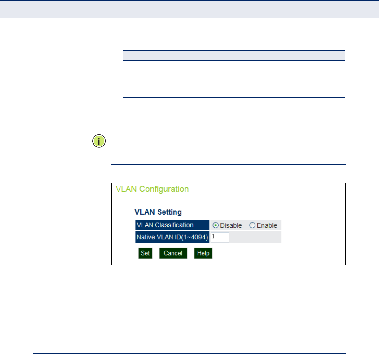
VLAN CONFIGURATION
VLANs (virtual local area networks) are turned off by default when first
installing the access point. If turned on they will automatically tag any
packets received by the WAN port before sending them on to the relevant
VAP (virtual access point).
The access point can employ VLAN tagging support to control access to
network resources and increase security. VLANs separate traffic passing
between the access point, associated clients, and the wired network. There
can be a VLAN assigned to each associated client, a default VLAN for each
VAP (Virtual Access Point) interface, and a management VLAN for the
access point.
Note the following points about the access point’s VLAN support:

C
HAPTER
5
| System Settings
VLAN Configuration
– 61 –
◆The management VLAN is for managing the access point through
remote management tools, such as the web interface, SSH, SNMP, or
Telnet. The access point only accepts management traffic that is tagged
with the specified management VLAN ID.
◆All wireless clients associated to the access point are assigned to a
VLAN. If IEEE 802.1X is being used to authenticate wireless clients,
specific VLAN IDs can be configured on the RADIUS server to be
assigned to each client. If a client is not assigned to a specific VLAN or
if 802.1X is not used, the client is assigned to the default VLAN for the
VAP interface with which it is associated. The access point only allows
traffic tagged with assigned VLAN IDs or default VLAN IDs to access
clients associated on each VAP interface.
◆When VLAN support is enabled on the access point, traffic passed to the
wired network is tagged with the appropriate VLAN ID, either an
assigned client VLAN ID, default VLAN ID, or the management VLAN ID.
Traffic received from the wired network must also be tagged with one of
these known VLAN IDs. Received traffic that has an unknown VLAN ID
or no VLAN tag is dropped.
◆When VLAN support is disabled, the access point does not tag traffic
passed to the wired network and ignores the VLAN tags on any received
frames.
N
OTE
:
Before enabling VLAN tagging on the access point, be sure to
configure the attached network switch port to support tagged VLAN frames
from the access point’s management VLAN ID, default VLAN IDs, and other
client VLAN IDs. Otherwise, connectivity to the access point will be lost
when you enable the VLAN feature.
Using IEEE 802.1X and a central RADIUS server, up to 64 VLAN IDs can be
mapped to specific wireless clients, allowing users to remain within the
same VLAN as they move around a campus site. This feature can also be
used to control access to network resources from clients, thereby
improving security.
A VLAN ID (1-4094) can be assigned to a client after successful IEEE
802.1X authentication. The client VLAN IDs must be configured on the
RADIUS server for each user authorized to access the network. If a client
does not have a configured VLAN ID on the RADIUS server, the access
point assigns the client to the configured default VLAN ID for the VAP
interface.
N
OTE
:
When using IEEE 802.1X to dynamically assign VLAN IDs, the access
point must have 802.1X authentication enabled and a RADIUS server
configured. Wireless clients must also support 802.1X client software.
C
HAPTER
5
| System Settings
System Logs
– 62 –
VLAN IDs on the RADIUS server can be entered as hexadecimal digits or a
string
The specific configuration of RADIUS server software is beyond the scope
of this guide. Refer to the documentation provided with the RADIUS server
software.
Figure 26: Setting the VLAN Identity
The following items are displayed on this page:
◆VLAN Classification — Enables/disables VLAN packet tagging.
(Default: disabled)
◆Native VLAN ID(1-4094) — If enabled the packets received by the
WAN port must be tagged within the native VLAN ID. (Range: 1-4094)
SYSTEM LOGS
The access point can be configured to send event and error messages to a
System Log Server. The system clock can also be synchronized with a time
server, so that all the messages sent to the Syslog server are stamped with
the correct time and date.
Table 3: RADIUS Attributes
Number RADIUS Attribute Value
64 Tunnel-Type VLAN (13)
65 Tunnel-Medium-Type 802
81 Tunnel-Private-Group-ID VLANID
(1 to 4094 as hexadecimal or string)
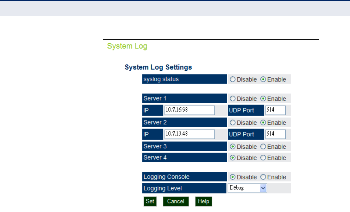
C
HAPTER
5
| System Settings
System Logs
– 63 –
Figure 27: System Log Settings
The following items are displayed on this page:
◆syslog status — Enables/disables the logging of error messages.
(Default: enabled)
◆Server 1~4 — Enables the sending of log messages to a Syslog server
host. Up to four Syslog servers are supported on the access point.
(Default: disabled)
◆IP — The IP address or name of a Syslog server. (Server 1 Default:
10.7.16.98; Server 2 Default: 10.7.13.48; Server 3 Default:
10.7.123.123; Server 4 Default: 10.7.13.77)
◆UDP Port — The UDP port used by a Syslog server. (Range: 514 or
11024-65535; Server 1~2 Default: 514; Server 3 Default: 6553;
Server 4 Default: 5432)
◆Logging Console — Enables the logging of error messages to the
console. (Default: disabled)
◆Logging Level — Sets the minimum severity level for event logging.
(Default: Debug)
■The system allows you to limit the messages that are logged by
specifying a minimum severity level. The following table lists the
error message levels from the most severe (Emergency) to least

C
HAPTER
5
| System Settings
Quick Start Wizard
– 64 –
severe (Debug). The message levels that are logged include the
specified minimum level up to the Emergency level.
QUICK START WIZARD
The Quick Start menu item is described in the preceding chapter, see
“Quick Start” on page 46.
Table 4: Logging Levels
Error Level Description
Emergency System unusable
Alerts Immediate action needed
Critical Critical conditions (e.g., memory allocation, or free memory error - resource exhausted)
Error Error conditions (e.g., invalid input, default used)
Warning Warning conditions (e.g., return false, unexpected return)
Notice Normal but significant condition, such as cold start
Informational Informational messages only
Debug Debugging messages

– 65 –
6MANAGEMENT SETTINGS
This chapter describes management access settings on the access point. It
includes the following sections:
◆“Remote Management Settings” on page 65
◆“Access Limitation” on page 67
◆“Simple Network Management Protocol” on page 68
REMOTE MANAGEMENT SETTINGS
The Web, Telnet, and SNMP management interfaces are enabled and open
to all IP addresses by default. To provide more security for management
access to the access point, specific interfaces can be disabled and
management restricted to a single IP address or a limited range of IP
addresses.
Once you specify an IP address or range of addresses, access to
management interfaces is restricted to the specified addresses. If anyone
tries to access a management interface from an unauthorized address, the
access point will reject the connection.
Telnet is a remote management tool that can be used to configure the
access point from anywhere in the network. However, Telnet is not secure
from hostile attacks. The Secure Shell (SSH) can act as a secure
replacement for Telnet. The SSH protocol uses generated public keys to
encrypt all data transfers passing between the access point and SSH-
enabled management station clients and ensures that data traveling over
the network arrives unaltered. Clients can then securely use the local user
name and password for access authentication.
Note that SSH client software needs to be installed on the management
station to access the access point for management via the SSH protocol.
Both HTTP and HTTPS service can be enabled independently. If you enable
HTTPS, you must indicate this in the URL: https://device:port_number]
When you start HTTPS, the connection is established in this way:
◆The client authenticates the server using the server’s digital certificate.
◆The client and server negotiate a set of security protocols to use for the
connection.

C
HAPTER
6
| Management Settings
Remote Management Settings
– 66 –
◆The client and server generate session keys for encrypting and
decrypting data.
◆The client and server establish a secure encrypted connection.
◆A padlock icon should appear in the status bar for Internet Explorer 5.x.
Figure 28: Remote Management
The following items are displayed on Admin Interface page:
◆Telnet Access — Enables/disables management access from Telnet
interfaces. (Default: enabled)
◆Telnet Access Port — Sets the specified Telnet port for
communication. (Default: 23)
◆SSH Server — Enables/disables management access from SSH
Servers. (Default: enabled)
◆SSH Server Port — Sets the specified SSH Server port for
communication. (Default: 22)
◆HTTP Access — Enables/disables management access from any IP
address. (Default: enabled)
◆HTTP Timeout — Specifies the time after which the HTTP connection
will be lost with a period of inactivity. (Default: 1800 seconds; Range:
1-1800 seconds; 0=disabled)
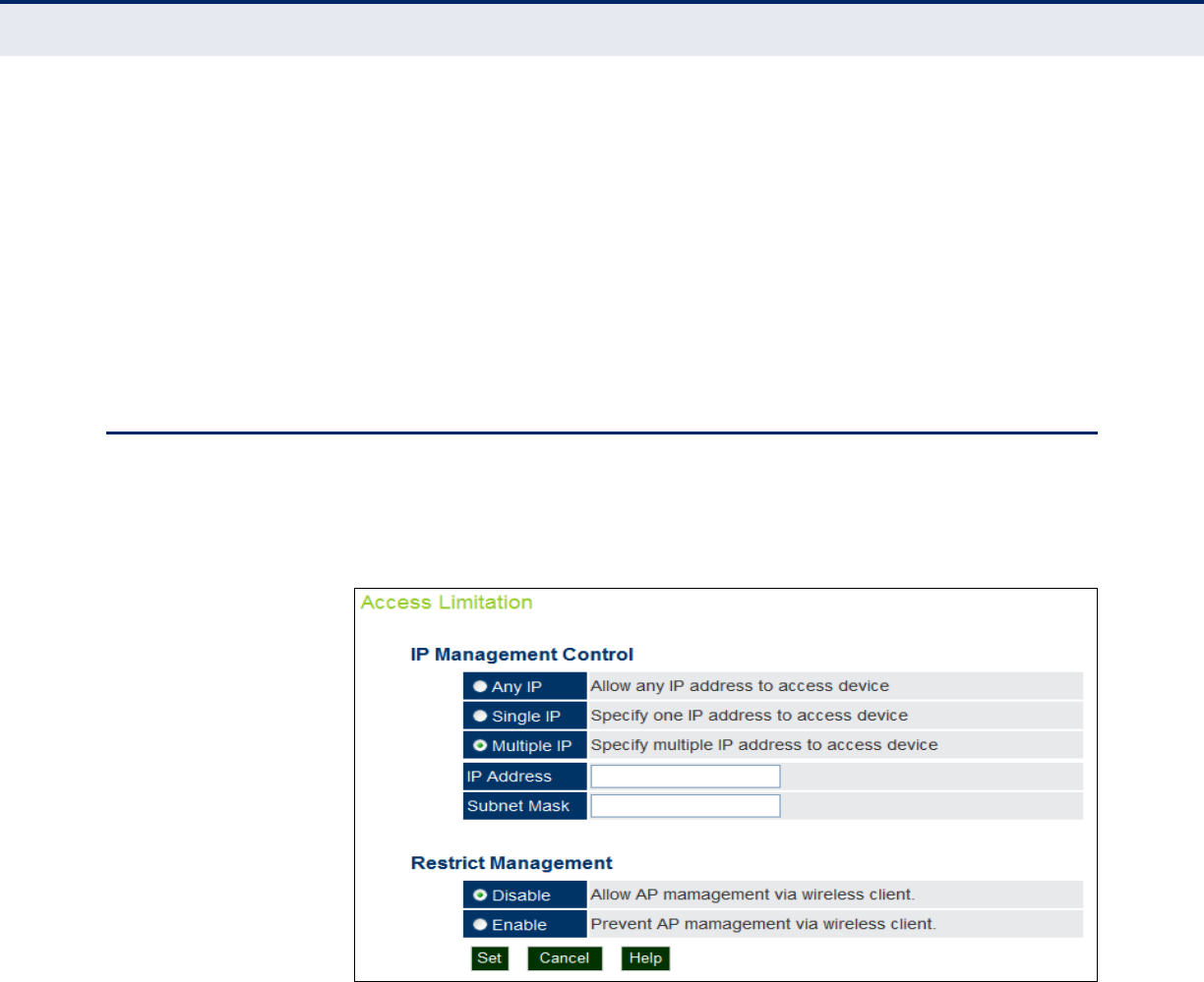
C
HAPTER
6
| Management Settings
Access Limitation
– 67 –
◆HTTP Port — Specifies the HTTP port for IP connectivity. (Default: 80;
Range 1024-65535)
◆HTTPS Server — Enables/disables management access from a HTTPS
server. (Default: enabled)
◆HTTPS Port — Specifies the HTTPS port for secure IP connectivity.
(Default: 443; Range 1024-65535)
◆SNMP Access — Enables/disables management access from SNMP
interfaces. (Default: enabled)
ACCESS LIMITATION
The Access Limitation page limits management access to the access point
from specified IP addresses or wireless clients.
Figure 29: Access Limitation
The following items are displayed on the Access Limitation page:
IP MANAGEMENT CONTROL
◆Any IP — Indicates that any IP address is allowed management
access.
◆Single IP — Specifies a single IP address that is allowed management
access.
◆Multiple IP — Specifies an address range as defined by the entered IP
address and subnet mask. For example, IP address 192.168.1.6 and
subnet mask 255.255.255.0, defines all IP addresses from 192.168.1.1
to 192.168.1.254.

C
HAPTER
6
| Management Settings
Simple Network Management Protocol
– 68 –
◆IP Address — Specifies the IP address.
◆Subnet Mask — Specifies the subnet mask in the form 255.255.255.x
RESTRICT MANAGEMENT
◆Enable/Disable — Enables/disables management of the device by a
wireless client. (Default: disabled)
SIMPLE NETWORK MANAGEMENT PROTOCOL
Simple Network Management Protocol (SNMP) is a communication protocol
designed specifically for managing devices on a network. Equipment
commonly managed with SNMP includes switches, routers and host
computers. SNMP is typically used to configure these devices for proper
operation in a network environment, as well as to monitor them to evaluate
performance or detect potential problems.
Managed devices supporting SNMP contain software, which runs locally on
the device and is referred to as an agent. A defined set of variables, known
as managed objects, is maintained by the SNMP agent and used to manage
the device. These objects are defined in a Management Information Base
(MIB) that provides a standard presentation of the information controlled
by the agent. SNMP defines both the format of the MIB specifications and
the protocol used to access this information over the network.
The access point includes an onboard agent that supports SNMP versions
1, 2c, and 3 clients. This agent continuously monitors the status of the
access point, as well as the traffic passing to and from wireless clients. A
network management station can access this information using SNMP
management software that is compliant with MIB II. To implement SNMP
management, the access point must first have an IP address and subnet
mask, configured either manually or dynamically. Access to the onboard
agent using SNMP v1 and v2c is controlled by community strings. To
communicate with the access point, the management station must first
submit a valid community string for authentication.
Access to the access point using SNMP v3 provides additional security
features that cover message integrity, authentication, and encryption; as
well as controlling notifications that are sent to specified user targets.
SNMP BASIC
SETTINGS
The access point SNMP agent must be enabled to function (for versions 1,
2c, and 3 clients). Management access using SNMP v1 and v2c also
requires community strings to be configured for authentication. Trap
notifications can be enabled and sent to up to four management stations.
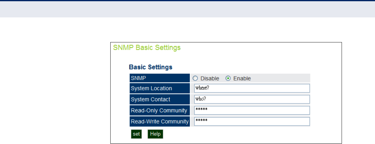
C
HAPTER
6
| Management Settings
Simple Network Management Protocol
– 69 –
Figure 30: SNMP Basic Settings
The following items are displayed on this page:
◆SNMP — Enables or disables SNMP management access and also
enables the access point to send SNMP traps (notifications). (Default:
Disable)
◆System Location — A text string that describes the system location.
(Maximum length: 255 characters)
◆System Contact — A text string that describes the system contact.
(Maximum length: 255 characters)
◆Read-Only Community — Defines the SNMP community access string
that has read-only access. Authorized management stations are only
able to retrieve MIB objects. (Maximum length: 23 characters, case
sensitive; Default: public)
◆Read-Write Community — Defines the SNMP community access
string that has read/write access. Authorized management stations are
able to both retrieve and modify MIB objects. (Maximum length: 23
characters, case sensitive; Default: private)
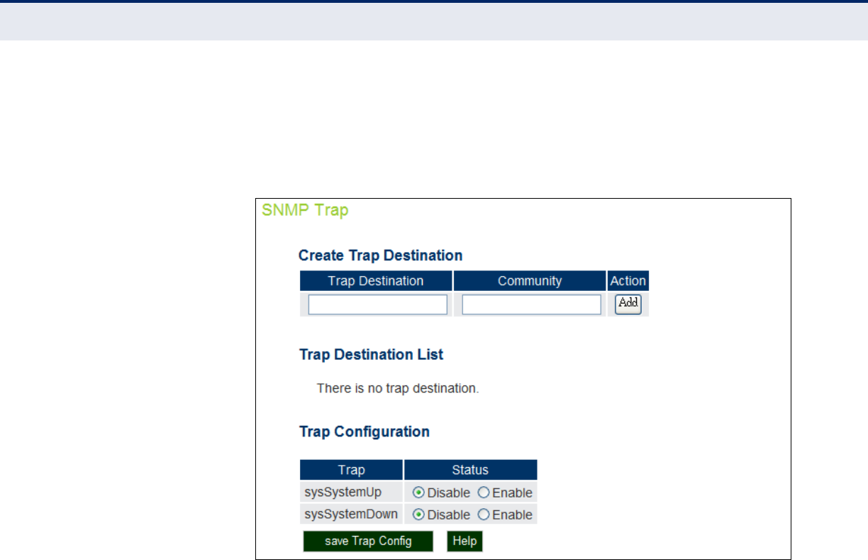
C
HAPTER
6
| Management Settings
Simple Network Management Protocol
– 70 –
SNMP TRAP SETTINGS Traps indicating status changes are issued by the AP to specified trap
managers. You must specify trap managers so that key events are reported
by the AP to your management station (using network management
platforms).
Figure 31: SNMP Trap Settings
The following items are displayed on this page:
◆Trap Destination — Specifies the recipient of SNMP notifications.
Enter the IP address or the host name. (Host Name: 1 to 63 characters,
case sensitive)
◆Community — The community string sent with the notification
operation. (Maximum length: 23 characters, case sensitive; Default:
public)
◆Action — Adds a new SNMP trap destination to the list.
◆Trap Destination List — Lists the configured SNMP trap destinations.
◆Trap Configuration — Enables or disables trap status.
■sysSystemUp: The access point is up and running.
■sysSystemDown: The access point is about to shutdown and
reboot.
◆save Trap Config — Applies the new parameters and saves them to
RAM memory. Also prompts a screen to inform you when it has taken
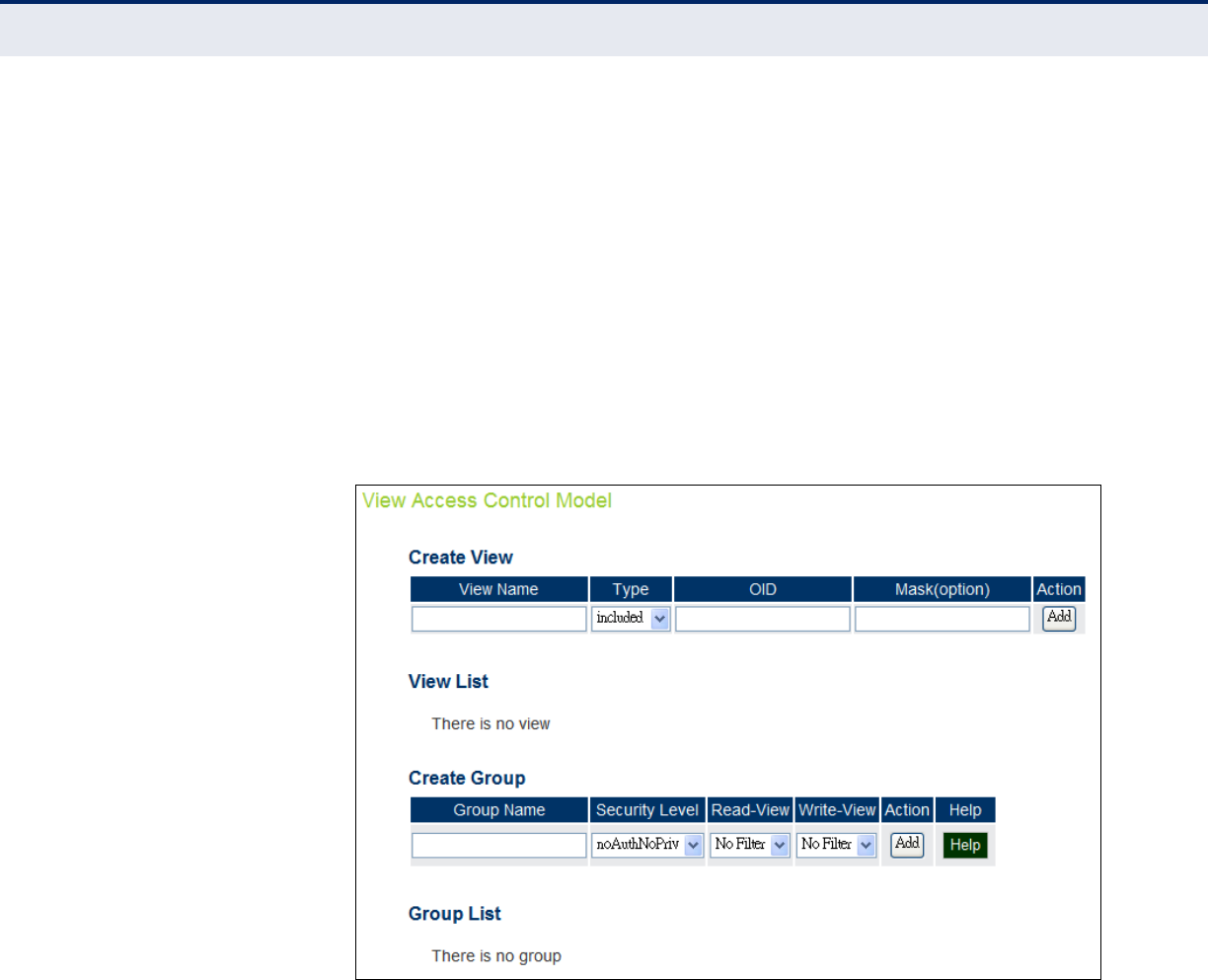
C
HAPTER
6
| Management Settings
Simple Network Management Protocol
– 71 –
affect. Clicking ‘OK’ returns to the home page. Changes will not be
saved upon a reboot unless the running configuration file is saved.
VIEW ACCESS
CONTROL MODEL
To configure SNMPv3 management access to the AP, follow these steps:
1. Specify read and write access views for the AP MIB tree.
2. Configure SNMP user groups with the required security model (that is,
SNMP v1, v2c, or v3) and security level (authentication and privacy).
3. Assign SNMP users to groups, along with their specific authentication
and privacy passwords.
Figure 32: SNMP VACM
CREATING VIEWS
SNMPv3 views are used to restrict user access to specified portions of the
MIB tree. The are no predefined views by default.
The following items are displayed on the VACM page.
◆View Name – The name of the SNMP view. (Range: 1-32 characters)
◆Type – Indicates if the object identifier of a branch within the MIB tree
is included or excluded from the SNMP view.
◆OID – Allows you to configure the object identifiers of branches within
the MIB tree. Wild cards can be used to mask a specific portion of the
OID string.

C
HAPTER
6
| Management Settings
Simple Network Management Protocol
– 72 –
◆Mask (option) – A hexadecimal value with each bit masking the
corresponding ID in the MIB subtree. A “1” in the mask indicates an
exact match and a “0” indicates a “wild card.” For example, a mask
value of 0xFFBF provides a bit mask “1111 1111 1011 1111.” If applied
to the subtree “1.3.6.1.2.1.2.2.1.1.23,” the zero corresponds to the
10th subtree ID. When there are more subtree IDs than bits in the
mask, the mask is padded with ones.
◆View List – Shows the currently configured object identifiers of
branches within the MIB tree that define the SNMP view.
CREATING GROUPS
An SNMPv3 group sets the access policy for its assigned users, restricting
them to specific read, write, and notify views. You can create new groups
to map a set of SNMP users to SNMP views.
◆Group Name – The name of the SNMP group. (Range: 1-32
characters)
◆Security Level – The security level used for the group:
■noAuthNoPriv – There is no authentication or encryption used in
SNMP communications.
■AuthNoPriv – SNMP communications use authentication, but the
data is not encrypted.
■AuthPriv – SNMP communications use both authentication and
encryption.
◆Read View – The configured view for read access. (Range: 1-32
characters)
◆Write View – The configured view for write access. (Range: 1-32
characters)
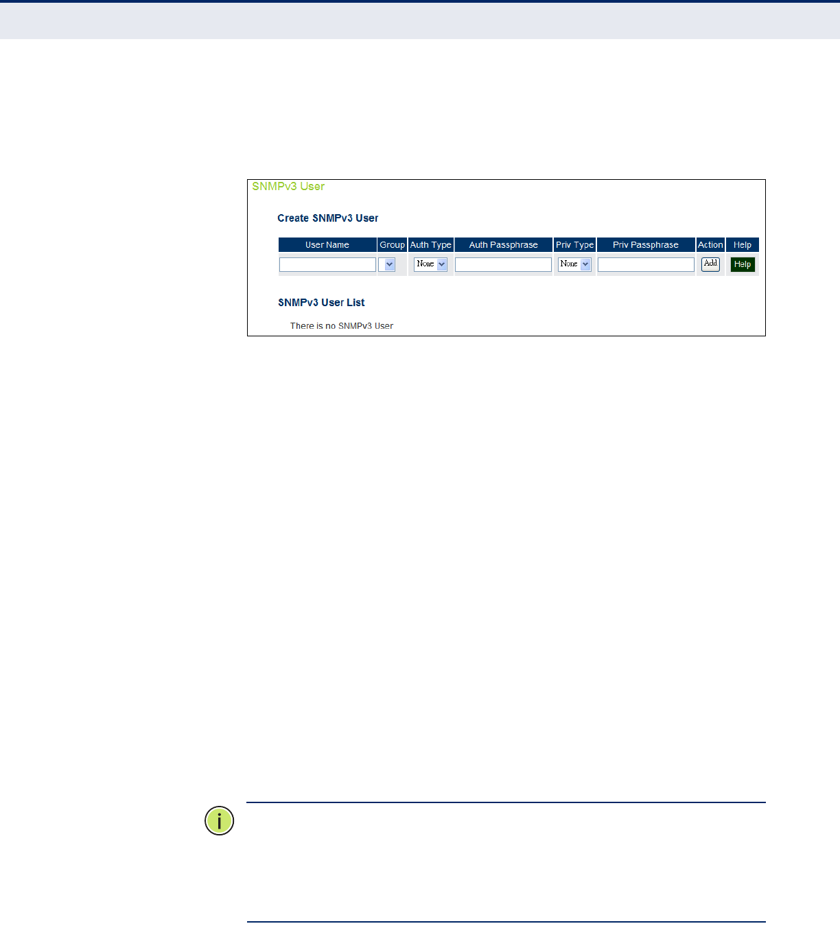
C
HAPTER
6
| Management Settings
Simple Network Management Protocol
– 73 –
SNMPV3 USERS The access point allows up to 10 SNMP v3 users to be configured. Each
SNMPv3 user is defined by a unique name. Users must be configured with a
specific security level and assigned to a group. The SNMPv3 group restricts
users to a specific read, write, or notify view.
Figure 33: Configuring SNMPv3 Users
The following items are displayed on this page:
◆User Name — The SNMPv3 user name. (32 characters maximum)
◆Group — The SNMPv3 group name.
◆Auth Type — The authentication type used for the SNMP user; either
MD5 or none. When MD5 is selected, enter a password in the
corresponding Passphrase field.
◆Auth Passphrase — The authentication password or key associated
with the authentication and privacy settings. A minimum of eight plain
text characters is required.
◆Priv Type — The data encryption type used for the SNMP user; either
DES or none. When DES is selected, enter a key in the corresponding
Passphrase field.
◆Priv Passphrase — The password or key associated with the
authentication and privacy settings. A minimum of eight plain text
characters is required.
◆Action — Click the Add button to add a new user to the list. Click the
edit button to change details of an existing user. Click the Del button to
remove a user from the list.
N
OTE
:
Users must be assigned to groups that have the same security
levels. For example, a user who has “Auth Type” and “Priv Type” configured
to MD5 and DES respectively (that it, uses both authentication and data
encryption) must be assigned to the RWPriv group. If this same user were
instead assigned to the read-only (RO) group, the user would not be able
to access the database.
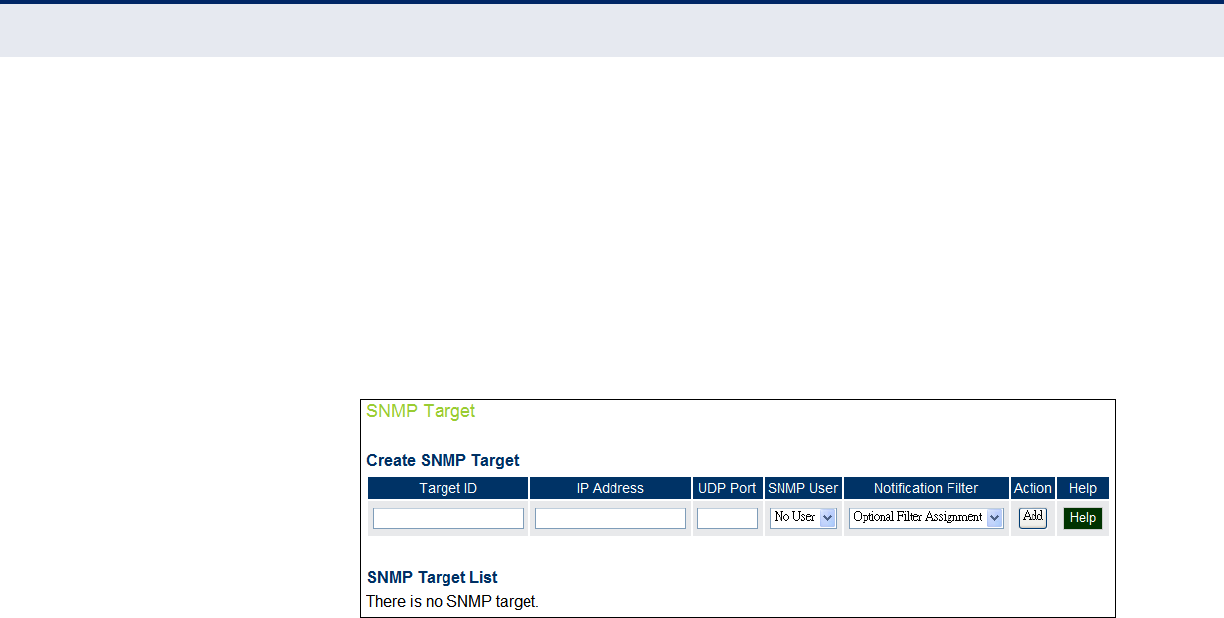
C
HAPTER
6
| Management Settings
Simple Network Management Protocol
– 74 –
SNMPV3 TARGETS An SNMP v3 notification Target ID is specified by the SNMP v3 user, IP
address, and UDP port. A user-defined filter can also be assigned to
specific targets to limit the notifications received to specific MIB objects.
(Note that the filter must first be configured. See “SNMPv3 Notification
Filters” on page 74.)
To configure a new notification receiver target, define the parameters and
select a filter, if required. Note that the SNMP v3 user name must first be
defined (See “SNMPv3 Users” on page 73.)
Figure 34: SNMPv3 Targets
The following items are displayed on this page:
◆Target ID — A user-defined name that identifies a receiver of
notifications. The access point supports up to 10 target IDs. (Maximum
length: 32 characters)
◆IP Address — Specifies the IP address of the receiving management
station.
◆UDP Port — The UDP port that is used on the receiving management
station for notification messages.
◆SNMP User — The defined SNMP v3 user that is to receive notification
messages.
◆Notification Filter — The name of a user-defined notification filter
that is applied to the target.
SNMPV3
NOTIFICATION FILTERS
SNMP v3 users can be configured to receive notification messages from the
access point. An SNMP Target ID is created that specifies the SNMP v3 user,
IP address, and UDP port. A user-defined notification filter can be created
so that specific notifications can be prevented from being sent to particular
targets.
The access point allows up to 10 notification filters to be created. Each
filter can be defined by up to 20 MIB subtree ID entries.
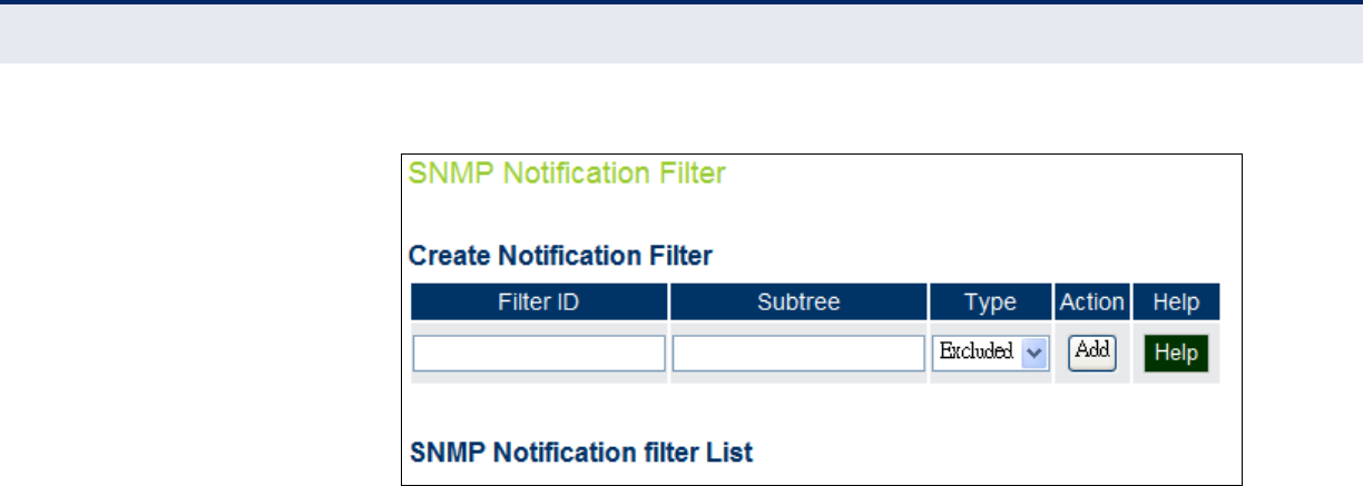
C
HAPTER
6
| Management Settings
Simple Network Management Protocol
– 75 –
Figure 35: SNMP Notification Filter
The following items are displayed on this page:
◆Filter ID — A user-defined name that identifies the filter. (Maximum
length: 32 characters)
◆Subtree — Specifies MIB subtree to be filtered. The MIB subtree must
be defined in the form “.1.3.6.1” and always start with a “.”.
◆Type — Indicates if the filter is to “include” or “exclude” the MIB
subtree objects from the filter. Note that MIB objects included in the
filter are not sent to the receiving target and objects excluded are sent.
By default all traps are sent, so you can first use an “include” filter
entry for all trap objects. Then use “exclude” entries for the required
trap objects to send to the target. Note that the filter entries are
applied in the sequence that they are defined.
◆Action — Adds the notification filter.
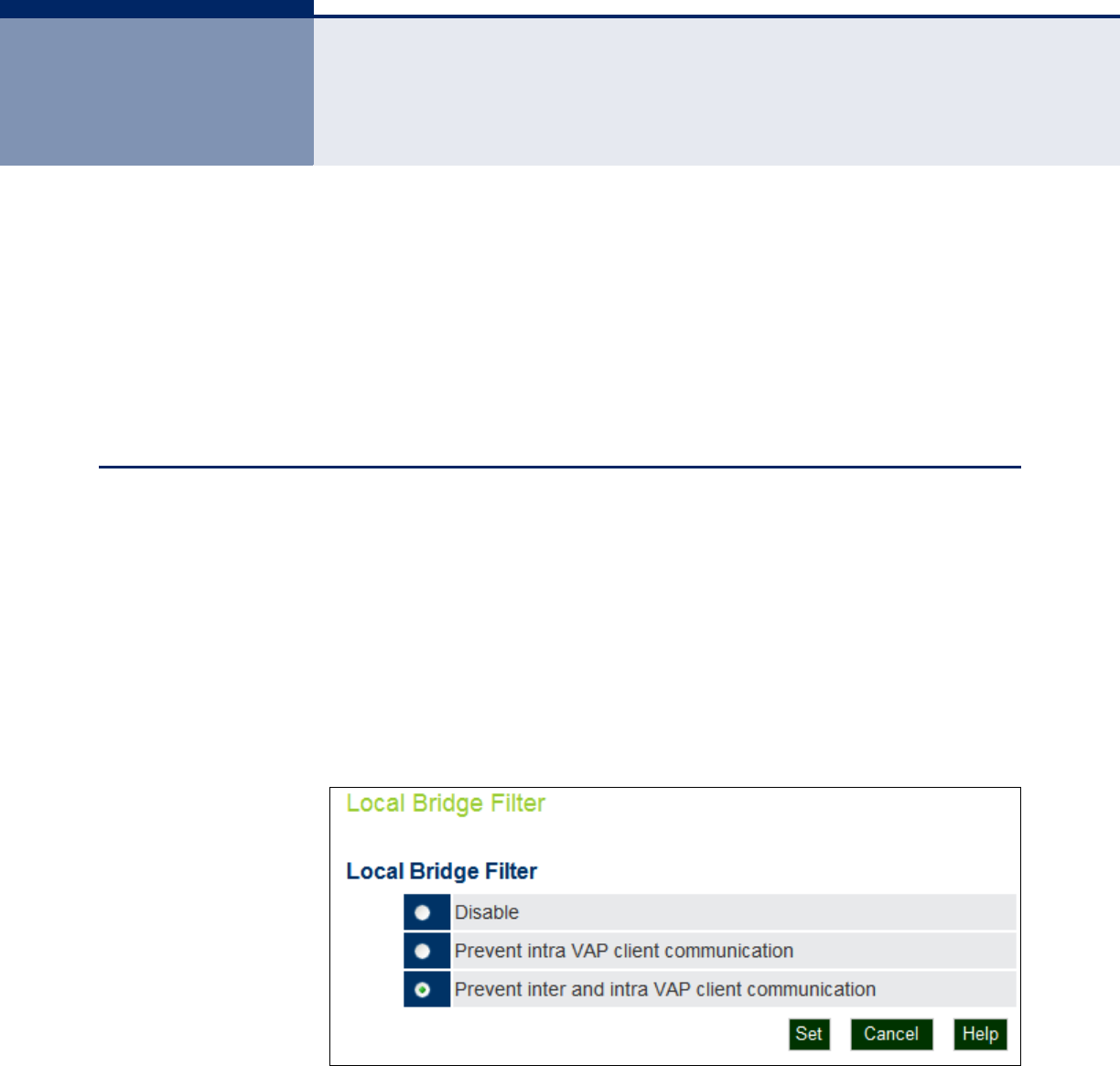
– 76 –
7ADVANCED SETTINGS
This chapter describes advanced settings on the access point. It includes
the following sections:
◆“Local Bridge Filter” on page 76
◆“Link Layer Discovery Protocol” on page 77
◆“Access Control Lists” on page 78
LOCAL BRIDGE FILTER
The access point can employ network traffic frame filtering to control
access to network resources and increase security. You can prevent
communications between wireless clients and prevent access point
management from wireless clients. Also, you can block specific Ethernet
traffic from being forwarded by the access point.
Inter Client STAs Communication Filter – Sets the global mode for wireless-
to-wireless communications between clients associated to Virtual AP (VAP)
interfaces on the access point. (Default: Prevent Inter and Intra VAP client
Communication)
Figure 36: Local Bridge Filter
The following items are displayed on this page:
◆Disabled — All clients can communicate with each other through the
access point.

C
HAPTER
7
| Advanced Settings
Link Layer Discovery Protocol
– 77 –
◆Prevent Intra VAP client communication — When enabled, clients
associated with a specific VAP interface cannot establish wireless
communications with each other. Clients can communicate with clients
associated to other VAP interfaces.
◆Prevent Inter and Intra VAP client communication — When
enabled, clients cannot establish wireless communications with any
other client, either those associated to the same VAP interface or any
other VAP interface.
LINK LAYER DISCOVERY PROTOCOL
This page allows you to configure the Link Layer Discovery Protocol (LLDP).
LLDP allows devices in the local broadcast domain to share information
about themselves. LLDP-capable devices periodically transmit information
in messages called Type Length Value (TLV) fields to neighbor devices.
Advertised information is represented in Type Length Value (TLV) format
according to the IEEE 802.1ab standard, and can include details such as
device identification, capabilities and configuration settings.
This information can be used by SNMP applications to simplify
troubleshooting, enhance network management, and maintain an accurate
network topology.
Figure 37: LLDP Settings
The following items are displayed on this page:
◆Disable/Enable — Disables/Enables LLDP on the access point.

C
HAPTER
7
| Advanced Settings
Access Control Lists
– 78 –
◆Message Transmission Hold Time — Configures the time-to-live
(TTL) value sent in LLDP advertisements as shown in the formula
below. (Range: 2-10; Default: 4)
The time-to-live tells the receiving LLDP agent how long to retain all
information pertaining to the sending LLDP agent if it does not transmit
updates in a timely manner. TTL in seconds is based on the following
rule: (Transmission Interval * Hold time) ? 65536. Therefore, the
default TTL is 4*30 = 120 seconds.
◆Message Transmission Interval (seconds) — Configures the
periodic transmit interval for LLDP advertisements. (Range: 5-32768
seconds; Default: 30 seconds)
This attribute must comply with the following rule: (Transmission
Interval * Hold Time) ? 65536, and Transmission Interval >= (4 *
Delay Interval)
◆ReInitial Delay Time (seconds) — Configures the delay before
attempting to re-initialize after LLDP ports are disabled or the link goes
down. (Range: 1-10 seconds; Default: 2 seconds)
When LLDP is re-initialized on a port, all information in the remote
systems LLDP MIB associated with this port is deleted.
◆Transmission Delay Value (seconds) — Configures a delay between
the successive transmission of advertisements initiated by a change in
local LLDP MIB variables. (Range: 1-8192 seconds; Default: 4 seconds)
The transmit delay is used to prevent a series of successive LLDP
transmissions during a short period of rapid changes in local LLDP MIB
objects, and to increase the probability that multiple, rather than single
changes, are reported in each transmission.
This attribute must comply with the rule: (4 * Delay Interval) ?
Transmission Interval
ACCESS CONTROL LISTS
Access Control Lists allow you to configure a list of wireless client MAC
addresses that are not authorized to access the network. A database of
MAC addresses can be configured locally on the access point.
SOURCE ADDRESS
SETTINGS
The ACL Source Address Settings page enables traffic filtering based on the
source MAC address in the data frame.
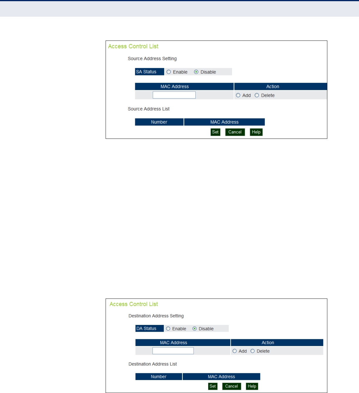
C
HAPTER
7
| Advanced Settings
Access Control Lists
– 79 –
Figure 38: Source ACLs
The following items are displayed on this page:
◆SA Status — Enables network traffic with specific source MAC
addresses to be filtered (dropped) from the access point.
◆MAC Address — Specifies a source MAC address to filter, in the form
xx.xx.xx.xx.xx.xx, or xx-xx-xx-xx-xx-xx.
◆Action — Selecting “Add” adds a new MAC address to the filter list,
selecting delete removes the specified MAC address.
◆Number — Specifies the number associated with the MAC address.
◆MAC Address — Displays the configured source MAC address.
DESTINATION
ADDRESS SETTINGS
The ACL Destination Address Settings page enables traffic filtering based
on the destination MAC address in the data frame.
Figure 39: Destination ACLs

C
HAPTER
7
| Advanced Settings
Access Control Lists
– 80 –
The following items are displayed on this page:
◆DA Status — Enables/disables the destination address to be filtered.
◆MAC Address — Specifies a destination MAC address to filter, in the
form xx.xx.xx.xx.xx.xx.
◆Action — Selecting “Add” adds a new MAC address to the filter list,
selecting delete deletes the specified MAC address.
◆Number — Specifies the number associated with the MAC address, up
to a maximum of eight.
◆MAC Address — Displays the configured destination MAC address.
◆Set — Applies the new parameters and saves them to RAM memory.
Also prompts a screen to inform you when it has taken affect. Clicking
‘OK’ returns to the home page. Changes will not be saved upon a
reboot unless the running configuration file is saved.
◆Cancel — Cancels the newly entered settings and restores the
originals.
◆Help — Prompts the help window to appear.
ETHERNET TYPE The Ethernet Type Filter controls checks on the Ethernet type of all
incoming and outgoing Ethernet packets against the protocol filtering table.
(Default: Disabled)
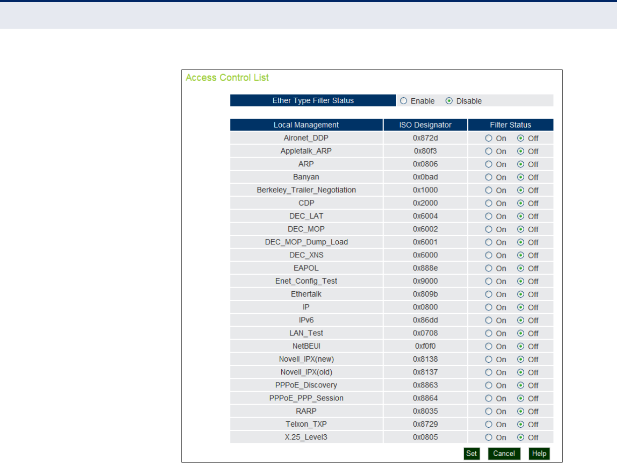
C
HAPTER
7
| Advanced Settings
Access Control Lists
– 81 –
Figure 40: Ethernet Type Filter
The following items are displayed on this page:
◆Disabled — Access point does not filter Ethernet protocol types.
◆Enabled — Access point filters Ethernet protocol types based on the
configuration of protocol types in the filter table. If the status of a
protocol is set to “ON,” the protocol is filtered from the access point.
◆Local Management — Describes the Ethernet filter type.
◆ISO Designator — Describes the ISO Designator identifyer.
◆Filter Status — Turns the filter on or off.

– 82 –
8WIRELESS SETTINGS
This chapter describes wireless settings on the access point. It includes the
following sections:
◆“Spanning Tree Protocol (STP)” on page 82
◆“Authentication” on page 85
◆“Radio Settings” on page 89
◆“Virtual Access Points (VAPs)” on page 93
◆“QoS” on page 99
SPANNING TREE PROTOCOL (STP)
The Spanning Tree Protocol (STP) can be used to detect and disable
network loops, and to provide backup links between switches, bridges or
routers. This allows the wireless bridge to interact with other bridging
devices (that is, an STP-compliant switch, bridge or router) in your network
to ensure that only one route exists between any two stations on the
network, and provide backup links which automatically take over when a
primary link goes down.
STP uses a distributed algorithm to select a bridging device (STP-compliant
switch, bridge or router) that serves as the root of the spanning tree
network. It selects a root port on each bridging device (except for the root
device) which incurs the lowest path cost when forwarding a packet from
that device to the root device. Then it selects a designated bridging device
from each LAN which incurs the lowest path cost when forwarding a packet
from that LAN to the root device. All ports connected to designated
bridging devices are assigned as designated ports. After determining the
lowest cost spanning tree, it enables all root ports and designated ports,
and disables all other ports. Network packets are therefore only forwarded
between root ports and designated ports, eliminating any possible network
loops.
Once a stable network topology has been established, all bridges listen for
Hello BPDUs (Bridge Protocol Data Units) transmitted from the root bridge.
If a bridge does not get a Hello BPDU after a predefined interval (Maximum
Age), the bridge assumes that the link to the root bridge is down. This
bridge will then initiate negotiations with other bridges to reconfigure the
network to reestablish a valid network topology.
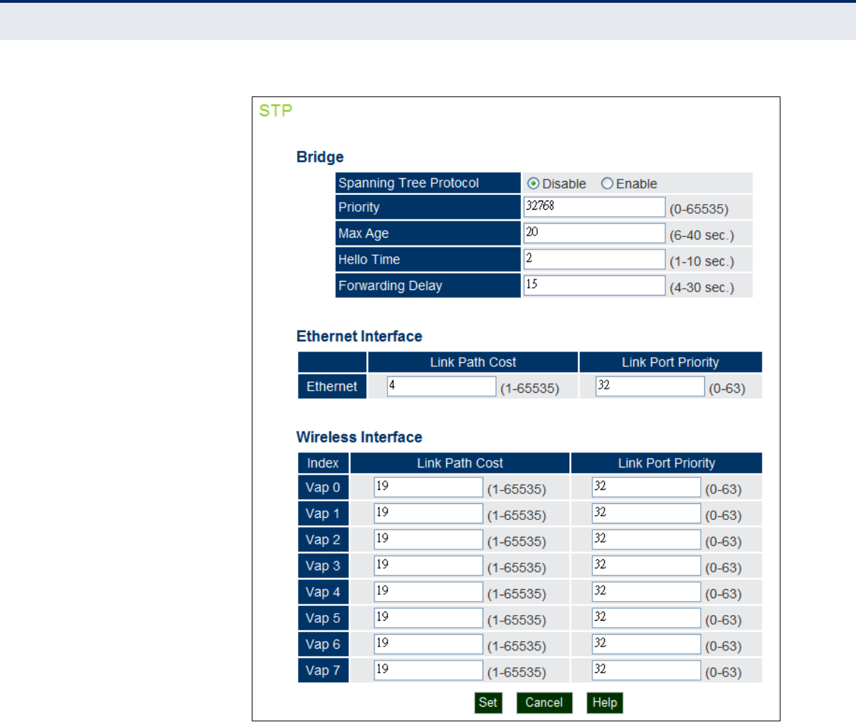
C
HAPTER
8
| Wireless Settings
Spanning Tree Protocol (STP)
– 83 –
Figure 41: Spanning Tree Protocol
BRIDGE Sets STP bridge link parameters.
The following items are displayed on the STP page:
◆Spanning Tree Protcol — Enables/disables STP on the wireless
bridge. (Default: Enabled)
◆Priority — Used in selecting the root device, root port, and designated
port. The device with the highest priority becomes the STP root device.
However, if all devices have the same priority, the device with the
lowest MAC address will then become the root device. (Note that lower

C
HAPTER
8
| Wireless Settings
Spanning Tree Protocol (STP)
– 84 –
numeric values indicate higher priority.)
(Default:32768; Range: 0-65535)
◆Max Age — The maximum time (in seconds) a device can wait without
receiving a configuration message before attempting to reconfigure. All
device ports (except for designated ports) should receive configuration
messages at regular intervals. Any port that ages out STP information
(provided in the last configuration message) becomes the designated
port for the attached LAN. If it is a root port, a new root port is selected
from among the device ports attached to the network.
(Default: 20 seconds; Range: 6-40 seconds)
■Minimum: The higher of 6 or [2 x (Hello Time + 1)].
■Maximum: The lower of 40 or [2 x (Forward Delay - 1)]
◆Hello Time — Interval (in seconds) at which the root device transmits
a configuration message. (Default: 2 seconds; Range: 1-10 seconds)
■Minimum: 1
■Maximum: The lower of 10 or [(Max. Message Age / 2) -1]
◆Forwarding Delay — The maximum time (in seconds) this device
waits before changing states (i.e., discarding to learning to forwarding).
This delay is required because every device must receive information
about topology changes before it starts to forward frames. In addition,
each port needs time to listen for conflicting information that would
make it return to a discarding state; otherwise, temporary data loops
might result. (Default: 15 seconds; Range: 4-30 seconds)
■Minimum: The higher of 4 or [(Max. Message Age / 2) + 1]
■Maximum: 30
ETHERNET INTERFACE Sets STP settings for the Ethernet port.
◆Link Path Cost — This parameter is used by the STP to determine the
best path between devices. Therefore, lower values should be assigned
to ports attached to faster media, and higher values assigned to ports
with slower media. (Path cost takes precedence over port priority.)
(Default: Ethernet interface: 19; Wireless interface: 40;
Range: 1-65535
◆Link Port Priority — Defines the priority used for this port in the
Spanning Tree Protocol. If the path cost for all ports on a switch are the
same, the port with the highest priority (i.e., lowest value) will be
configured as an active link in the spanning tree. This makes a port
with higher priority less likely to be blocked if the Spanning Tree
Protocol is detecting network loops. Where more than one port is
assigned the highest priority, the port with lowest numeric identifier will
be enabled. (Default: 128; Range: 0-240, in steps of 16)

C
HAPTER
8
| Wireless Settings
Authentication
– 85 –
WIRELESS INTERFACE Sets STP settings for the radio interface.
◆Index — Describes the VAP in question.
◆Link Path Cost — This parameter is used by the STP to determine the
best path between devices. Therefore, lower values should be assigned
to ports attached to faster media, and higher values assigned to ports
with slower media. (Path cost takes precedence over port priority.)
(Default: Ethernet interface: 19; Wireless interface: 40;
Range: 1-65535
◆Link Port Priority — Defines the priority used for this port in the
Spanning Tree Protocol. If the path cost for all ports on a switch are the
same, the port with the highest priority (i.e., lowest value) will be
configured as an active link in the spanning tree. This makes a port
with higher priority less likely to be blocked if the Spanning Tree
Protocol is detecting network loops. Where more than one port is
assigned the highest priority, the port with lowest numeric identifier will
be enabled. (Default: 128; Range: 0-240, in steps of 16)
AUTHENTICATION
Wireless clients can be authenticated for network access by checking their
MAC address against the local database configured on the access point, or
by using a database configured on a central RADIUS server. Alternatively,
authentication can be implemented using the IEEE 802.1X network access
control protocol.
The access point can also operate in a 802.1X supplicant mode. This
enables the access point itself and any bridge-connected units to be
authenticated with a RADIUS server using a configured MD5 user name
and password. This mechanism can prevent rogue access points from
gaining access to the network.
You can configure a list of the MAC addresses for wireless clients that are
authorized to access the network. This provides a basic level of
authentication for wireless clients attempting to gain access to the
network. A database of authorized MAC addresses can be stored locally on
the access point or remotely on a central RADIUS server. (Default: Local
MAC)
LOCAL
AUTHENTICATION
Local MAC Authentication – Configures the local MAC authentication
database. The MAC database provides a mechanism to take certain actions
based on a wireless client’s MAC address. The MAC list can be configured to
allow or deny network access to specific clients.
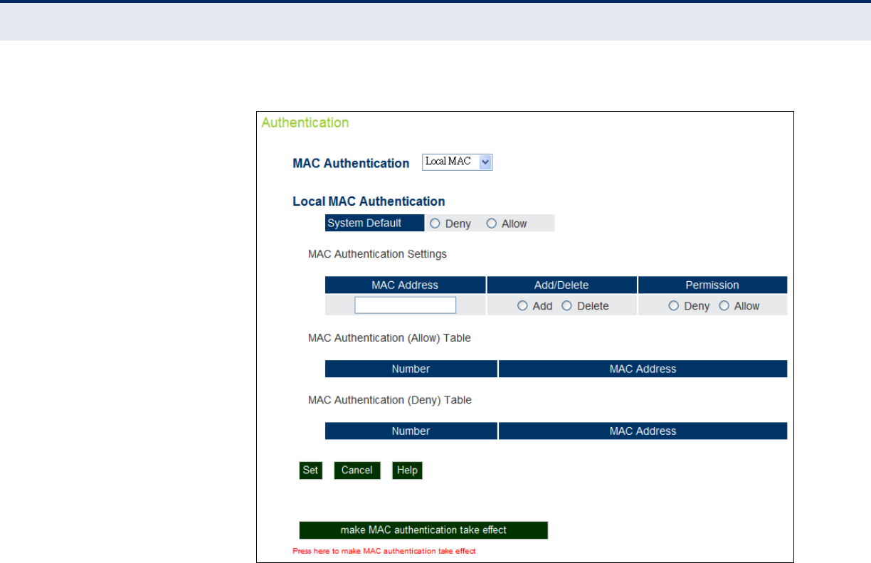
C
HAPTER
8
| Wireless Settings
Authentication
– 86 –
Figure 42: Local Authentication
The following items are displayed on Authentication page:
MAC Authentication — Selects between, disabled, Local MAC
authentication and RADIUS authentication.
◆Local MAC — The MAC address of the associating station is compared
against the local database stored on the access point. The Local MAC
Authentication section enables the local database to be set up.
◆System Default — Specifies a default action for all unknown MAC
addresses (that is, those not listed in the local MAC database).
■Deny: Blocks access for all MAC addresses except those listed in
the local database as “Allow.”
■Allow: Permits access for all MAC addresses except those listed in
the local database as “Deny.”
◆MAC Authentication Settings — Enters specified MAC addresses and
permissions into the local MAC database.
■MAC Address: Physical address of a client. Enter six pairs of
hexadecimal digits separated by hyphens; for example, 00-90-D1-
12-AB-89.
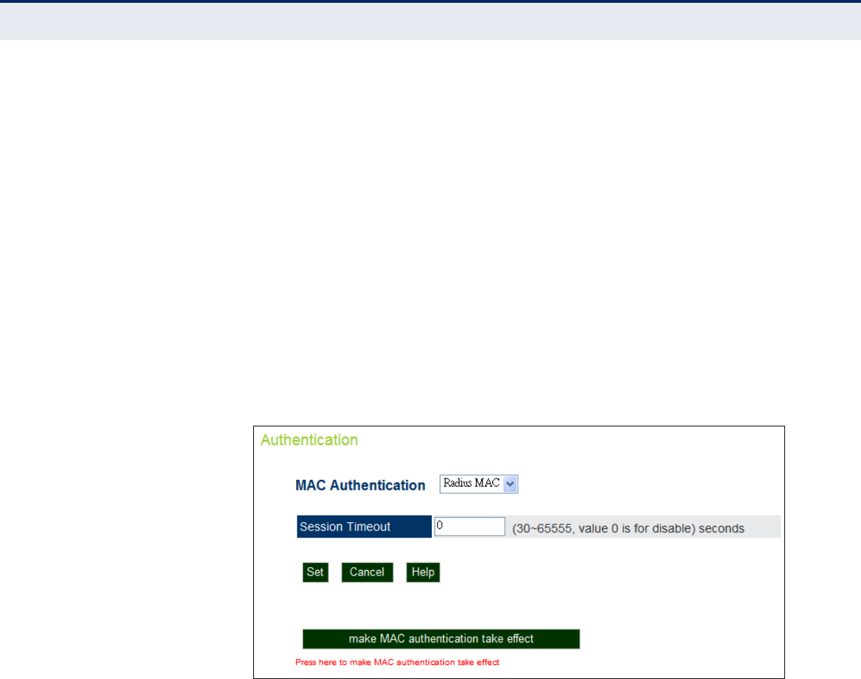
C
HAPTER
8
| Wireless Settings
Authentication
– 87 –
■Add/Delete: Adds or deletes the specified MAC address and
permission setting into or from the local database.
■Permission: Select Allow to permit access or Deny to block access.
If Delete is selected, the specified MAC address entry is removed
from the database.
◆MAC Authentication Table — Displays current entries in the local
MAC database.
◆make MAC authentication take effect — Applies the specified
settings.
RADIUS MAC
AUTHENTICATION
Radius MAC: The MAC address of the associating station is sent to a
configured RADIUS server for authentication. When using a RADIUS
authentication server for MAC address authentication, the server must first
be configured in the RADIUS window.
Figure 43: RADIUS Authentication
The following items are displayed on Authentication page:
MAC Authentication — Selects between, disabled, Local MAC
authentication and RADIUS authentication.
◆RADIUS MAC — The MAC address of the associating station is
compared against the RADIUS server database. The RADIUS MAC
Authentication section enables the RADIUS database to be set up.
◆Session Timeout — The time period after which a connected client
must be re-authenticated. During the re-authentication process of
verifying the client’s credentials on the RADIUS server, the client
remains connected the network. Only if re-authentication fails is
network access blocked. (Default: 0 means disabled; Range: 30-65535
seconds)
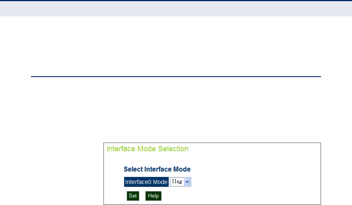
C
HAPTER
8
| Wireless Settings
Interface Mode
– 88 –
◆make MAC authentication take effect — Applies the specified
settings.
INTERFACE MODE
The access point can operate in two modes, IEEE 802.11a/n only, or
802.11g/n only. Also note that 802.11g is backward compatible with
802.11b. Also note that 802.11g is backward compatible with 802.11b,
operating in the 2.4 GHz band. The 802.11a/n mode operates in the 5 GHz
band.
Figure 44: Interface Mode
The following items are displayed on the Interface Mode Selection page:
◆Interface0 Mode — Selects the mode of the radio interface:
■11ng: All 802.11g and n clients can communicate with the wireless
AP/ Router (up to 300 Mbps) using the 2.4 GHz band, but data
transmission rates may be slowed to compensate for 802.11g
clients.
■11na: All 802.11a and n clients can communicate with the wireless
AP/ Router (up to 300 Mbps) using the 5 GHz band, but data
transmission rates may be slowed to compensate for 802.11a
clients.

C
HAPTER
8
| Wireless Settings
Radio Settings
– 89 –
RADIO SETTINGS
The IEEE 802.11n interfaces include configuration options for radio signal
characteristics and wireless security features.
The access point can operate in two modes, mixed 802.11g/n, or mixed
802.11a/n only. Also note that 802.11g is backward compatible with
802.11b, and 802.11n is backward compatible with both 802.11b/g and
802.11a at slower data transmit rates.
Each radio supports eight virtual access point (VAP) interfaces, referred to
as VAP0 ~ VAP7. Each VAP functions as a separate access point, and can
be configured with its own Service Set Identification (SSID) and security
settings. However, most radio signal parameters apply to both VAP
interfaces. The configuration options are nearly identical, and are therefore
both covered in this section of the manual. Traffic to specific VAPs can be
segregated based on user groups or application traffic. Both VAPs can have
up to 64 wireless clients, whereby the clients associate with these VAPs the
same as they would with a physical access point.
Packets from 802.11n clients are referred to as High Throughput (HT)
Greenfield packets, in other words packets that can be transmitted at rates
of up to 300 Mbps assuming that HT Channel Bandwidth is set to 20/
40Mhz, see HT Channel Bandwidth next page.
802.11b/g packets are referred to as non-HT packets, being transmitted at
lower throughput rates (see Radio Mode). HT mixed format frames contain
a preamble compatible with the non-HT receivers. HT Greenfield frames do
not contain a non-HT compatible part. Support for HT Greenfield format is
optional. An HT station that does not support the reception of an HT
Greenfield format frame must be able to detect that an HT Greenfield
format frame is an HT transmission (as opposed to a non-HT transmission).
In this case the receiver must decode the high throughput signal (HT-SIG)
in the packet header and determine if the HT-SIG cyclic redundancy check
(CRC) passes. (Default: Mixed)
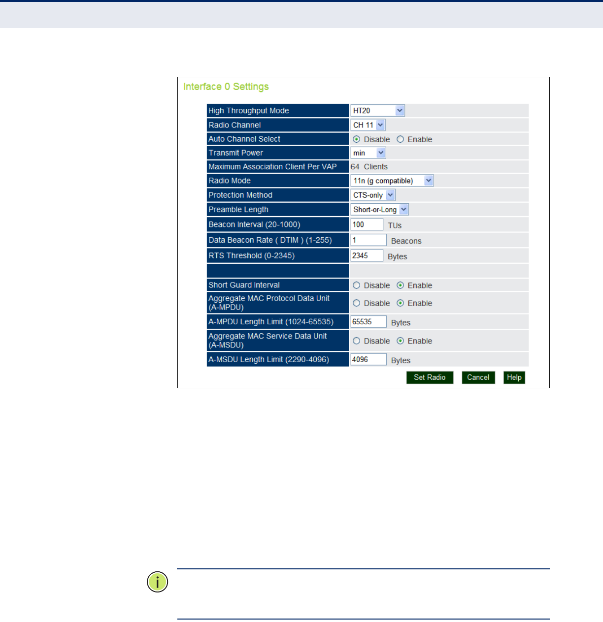
C
HAPTER
8
| Wireless Settings
Radio Settings
– 90 –
Figure 45: Radio Settings
The following items are displayed on this page:
◆High Throughput Mode — The access point provides a channel
bandwidth of 20 MHz by default giving an 802.11g connection speed of
54 Mbps and a 802.11n connection speed of up to 108 Mbps, and
ensures backward compliance for slower 802.11b devices. Setting the
HT Channel Bandwidth to 40 MHz (sometimes referred to as Turbo
Mode) increases connection speed for 802.11g and 802.11n to 74 Mbps
and 300 Mbps respectively. HT40plus indicates that the secondary
channel is above the primary channel. HT40minus indicates that the
secondary channel is below the primary channel.
(Default: HT20; Range:HT20, HT40PLUS, HT40MINUS)
N
OTE
:
Some 802.11n wireless clients may be capable of transmission rates
of up to 600 Mbps, however the access point will only be able to connect to
them at a maximum transmission rate of 300 Mbps.
◆Radio Channel — The radio channel that the access point uses to
communicate with wireless clients. When multiple access points are
deployed in the same area, set the channel on neighboring access
points at least five channels apart to avoid interference with each other.
For example, you can deploy up to three access points in the same area

C
HAPTER
8
| Wireless Settings
Radio Settings
– 91 –
using channels 1, 6, 11. Note that wireless clients automatically set the
channel to the same as that used by the access point to which it is
linked. (The supported channels are dependent on the country code
setting.)
◆Auto Channel Select — Selecting Auto Select enables the access point
to automatically select an unoccupied radio channel.
◆Transmit Power — Adjusts the power of the radio signals transmitted
from the access point. The higher the transmission power, the farther
the transmission range. Power selection is not just a trade off between
coverage area and maximum supported clients. You also have to
ensure that high-power signals do not interfere with the operation of
other radio devices in the service area. (Default: Minimum; Range:
min, 12.5%, 25%, 50%, 100%)
◆Maximum Association Client per VAP — The maximum number of
clients that may associate with each VAP is preset top 64.
◆Radio Mode — Defines the radio mode for the VAP interface. (Default:
11n (g compatible); Range: 11n (b&g compatible), 11n)
N
OTE
:
Enabling the access point to communicate with 802.11b/g clients in
both 802.11b/g/n Mixed and 802.11n modes also requires that HT
Operation be set to HT20.
◆Protection Method — Selects between Request to Send (RTS) and
mixed RTS-CTS (clear to send) packet transmission threshold.
◆Preamble Length — The radio preamble (sometimes called a header)
is a section of data at the head of a packet that contains information
that the wireless device and client devices need when sending and
receiving packets. You can set the radio preamble to long or short. A
short preamble improves throughput performance, whereas a long
preamble is required when legacy wireless devices are part of your
network.
◆Beacon Interval (20-1000) — The rate at which beacon signals are
transmitted from the access point. The beacon signals allow wireless
clients to maintain contact with the access point. They may also carry
power-management information. (Range: 20-1000 TUs; Default: 100
TUs)
◆Data Beacon Rate (DTIM) (1-255) — The rate at which stations in
sleep mode must wake up to receive broadcast/multicast
transmissions.
Known also as the Delivery Traffic Indication Map (DTIM) interval, it
indicates how often the MAC layer forwards broadcast/multicast traffic,
which is necessary to wake up stations that are using Power Save
mode. The default value of 2 indicates that the access point will save all
broadcast/multicast frames for the Basic Service Set (BSS) and forward
them after every second beacon. Using smaller DTIM intervals delivers

C
HAPTER
8
| Wireless Settings
Radio Settings
– 92 –
broadcast/multicast frames in a more timely manner, causing stations
in Power Save mode to wake up more often and drain power faster.
Using higher DTIM values reduces the power used by stations in Power
Save mode, but delays the transmission of broadcast/multicast frames.
(Range: 1-255 beacons; Default: 1 beacon)
◆RTS Threshold (0-2345) — Sets the packet size threshold at which a
Request to Send (RTS) signal must be sent to a receiving station prior
to the sending station starting communications. The access point sends
RTS frames to a receiving station to negotiate the sending of a data
frame. After receiving an RTS frame, the station sends a CTS (clear to
send) frame to notify the sending station that it can start sending data.
If the RTS threshold is set to 0, the access point always sends RTS
signals. If set to 2347, the access point never sends RTS signals. If set
to any other value, and the packet size equals or exceeds the RTS
threshold, the RTS/CTS (Request to Send / Clear to Send) mechanism
will be enabled.
The access points contending for the medium may not be aware of each
other. The RTS/CTS mechanism can solve this “Hidden Node Problem.”
(Range: 0-2345 bytes: Default: 2345 bytes)
◆Short Guard Interval — The 802.11n draft specifies two guard
intervals: 400ns (short) and 800ns (long). Support of the 400ns GI is
optional for transmit and receive. The purpose of a guard interval is to
introduce immunity to propagation delays, echoes, and reflections to
which digital data is normally very sensitive. Enabling the Short Guard
Interval sets it to 400ns. (Default: Disabled)
◆Aggregate MAC Protocol Data Unit (A-MPDU) — Enables / disables
the sending of this four frame packet header for statistical purposes.
(Default: Enabled)
◆A-MPDU Length Limit (1024-65535) — Defines the A-MPDU length.
(Default: 65535 bytes; Range: 1024-65535 bytes)
◆Aggregate MAC Service Data Unit (A-MSDU) — Enables / disables
the sending of this four frame packet header for statistical purposes.
(Default: Enabled)
◆A-MSDU Length Limit (2290-4096) — Defines the A-MSDU length.
(Default: 4096 bytes; Range: 2290-4096 bytes)
◆Set Radio — Sets all entered parameters.
◆Cancel — Cancels the newly entered settings and restores the
originals.
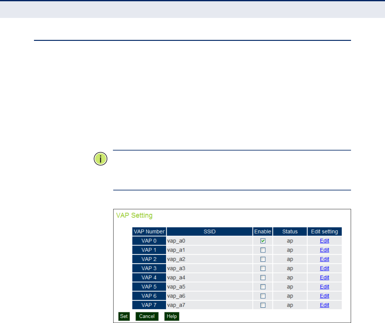
C
HAPTER
8
| Wireless Settings
Virtual Access Points (VAPs)
– 93 –
VIRTUAL ACCESS POINTS (VAPS)
The access point supports up to eight virtual access point (VAP) interfaces
numbered 0 to 7. Each VAP functions as a separate access point, and can
be configured with its own Service Set Identification (SSID) and security
settings. However, most radio signal parameters apply to all eight VAP
interfaces.
The VAPs function similar to a VLAN, with each VAP mapped to its own
VLAN ID. Traffic to specific VAPs can be segregated based on user groups
or application traffic. Each VAP can have up to 64 wireless clients, whereby
the clients associate with these VAPs the same as they would with a
physical access point.
N
OTE
:
The radio channel settings for the access point are limited by local
regulations, which determine the number of channels that are available.
Refer to “General Specifications” on page C-1 for additional information on
the maximum number channels available.
Figure 46: VAP Settings
The following items are displayed on this page:
◆VAP Number — The number associated with the VAP, 0-7.
◆SSID — The name of the basic service set provided by a VAP interface.
Clients that want to connect to the network through the access point
must set their SSID to the same as that of an access point VAP
interface. (Default: SMC_A # (0 to 7); Range: 1-32 characters)
◆Enable — Enables the specified VAP. (Default: Disabled)
◆Status — Displays the mode of the VAP. The default is set to "AP," for
normal access point services.
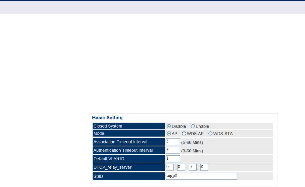
C
HAPTER
8
| Wireless Settings
Virtual Access Points (VAPs)
– 94 –
◆Edit Setting — CLicking “Edit” opens the dialogue box for configuring
the selected VAP.
VAP BASIC SETTINGS Sets the basic operating mode and other settings for the VAP.
Each VAP can operate in one of three modes; normal AP mode, WDS-AP
bridge root mode, or WDS-STA bridge station mode. The default mode is
AP for the VAP to support normal access point services.
Note that the Basic Settings are the same for both AP and WDS-AP modes.
Figure 47: VAP Basic Settings
The following items are displayed on this page:
◆Closed System — When enabled, the VAP does not include its SSID in
beacon messages. Nor does it respond to probe requests from clients
that do not include a fixed SSID. (Default: Disable)
◆Mode — Selects the mode in which the VAP will function.
■AP Mode: The VAP provides services to clients as a normal access
point.
■WDS-AP Mode: The VAP operates as an access point in WDS
mode, which accepts connections from client stations in WDS-STA
mode.
■WDS-STA Mode: The VAP operates as a client station in WDS
mode, which connects to an access point VAP in WDS-AP mode. The
user needs to specify the MAC address of the access point in WDS-
AP mode to which it intends to connect.
◆Association Timeout Interval — The idle time interval (when no
frames are sent) after which a client is disassociated from the VAP
interface. (Range: 5-60 minutes; Default: 30 minutes)
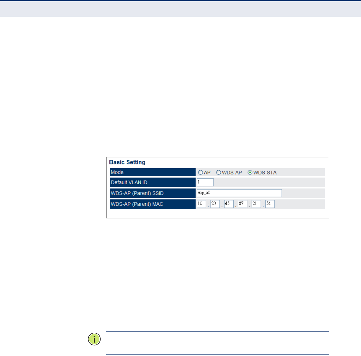
C
HAPTER
8
| Wireless Settings
Virtual Access Points (VAPs)
– 95 –
◆Authentication Timeout Interval — The time within which the client
should finish authentication before authentication times out.
(Range: 5-60 minutes; Default: 60 minutes)
◆Default VLAN ID — The VLAN ID assigned to wireless clients
associated to the VAP interface that are not assigned to a specific VLAN
by RADIUS server configuration. (Default: 1)
◆DHCP Relay Server — The IP address of the DHCP relay server.
◆SSID — The service set identifier for the VAP.
WDS-STA MODE Describes additional basic VAP settings when functioning in WDS-STA
mode.
Figure 48: WDS-STA Mode
The following items are displayed in the VAP Basic Settings when WDS-AP
mode is selected:
◆WDS-AP (Parent) SSID — The SSID of the VAP on the connecting
access point that is set to WDS-AP mode.
◆WDS-AP (Parent) MAC — The MAC address of the VAP on the
connecting access point that is set to WDS-AP mode.
WIRELESS SECURITY
SETTINGS
Describes the wireless security settings for each VAP, including association
mode, encryption, and authentication.
N
OTE
:
For VAPs set to WDS-AP or WDS-STA mode, the security options are
limited to WPA-PSK and WPA2-PSK only.
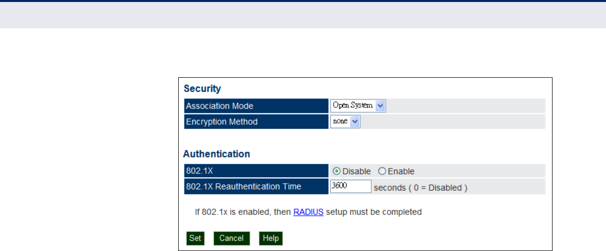
C
HAPTER
8
| Wireless Settings
Virtual Access Points (VAPs)
– 96 –
Figure 49: Configuring VAPs - Common Settings
The following items are common to all three modes:
◆Association Mode — Defines the mode with which the access point
will associate with other clients.
■Open System: The VAP is configured by default as an “open
system,” which broadcasts a beacon signal including the configured
SSID. Wireless clients with an SSID setting of “any” can read the
SSID from the beacon and automatically set their SSID to allow
immediate connection.
■WPA: WPA employs a combination of several technologies to
provide an enhanced security solution for 802.11 wireless networks.
■WPA-PSK: For enterprise deployment, WPA requires a RADIUS
authentication server to be configured on the wired network.
However, for small office networks that may not have the resources
to configure and maintain a RADIUS server, WPA provides a simple
operating mode that uses just a pre-shared password for network
access. The Pre-Shared Key mode uses a common password for
user authentication that is manually entered on the access point
and all wireless clients. The PSK mode uses the same TKIP packet
encryption and key management as WPA in the enterprise,
providing a robust and manageable alternative for small networks.
■WPA2: WPA2 – WPA was introduced as an interim solution for the
vulnerability of WEP pending the ratification of the IEEE 802.11i
wireless security standard. In effect, the WPA security features are
a subset of the 802.11i standard. WPA2 includes the now ratified
802.11i standard, but also offers backward compatibility with WPA.
Therefore, WPA2 includes the same 802.1X and PSK modes of
operation and support for TKIP encryption.
■WPA2-PSK: Clients using WPA2 with a Pre-shared Key are
accepted for authentication.

C
HAPTER
8
| Wireless Settings
Virtual Access Points (VAPs)
– 97 –
■WPA-WPA2 Mixed: Clients using WPA or WPA2 are accepted for
authentication.
■WPA-WPA2-PSK-mixed: Clients using WPA or WPA2 with a Pre-
shared Key are accepted for authentication.
◆Encryption Method — Selects an encryption method for the global
key used for multicast and broadcast traffic, which is supported by all
wireless clients.
■WEP: WEP is used as the multicast encryption cipher. You should
select WEP only when both WPA and WEP clients are supported.
■TKIP: TKIP is used as the multicast encryption cipher.
■AES-CCMP: AES-CCMP is used as the multicast encryption cipher.
AES-CCMP is the standard encryption cipher required for WPA2.
◆802.1X — The access point supports 802.1X authentication only for
clients initiating the 802.1X authentication process (i.e., the access
point does not initiate 802.1X authentication). For clients initiating
802.1X, only those successfully authenticated are allowed to access the
network. For those clients not initiating 802.1X, access to the network
is allowed after successful wireless association with the access point.
The 802.1X mode allows access for clients not using WPA or WPA2
security.
◆Pre-Authentication — When using WPA2 over 802.1X, pre-
authentication can be enabled, which allows clients to roam to a new
access point and be quickly associated without performing full 802.1X
authentication. (Default: Disabled)
◆802.1x Reauthentication Time — The time period after which a
connected client must be re-authenticated. During the re-
authentication process of verifying the client’s credentials on the
RADIUS server, the client remains connected the network. Only if re-
authentication fails is network access blocked. (Range: 0-65535
seconds; Default: 0 means disabled)
WIRED EQUIVALENT
PRIVACY (WEP)
WEP provides a basic level of security, preventing unauthorized access to
the network, and encrypting data transmitted between wireless clients and
the access point. WEP uses static shared keys (fixed-length hexadecimal or
alphanumeric strings) that are manually distributed to all clients that want
to use the network.
WEP is the security protocol initially specified in the IEEE 802.11 standard
for wireless communications. Unfortunately, WEP has been found to be
seriously flawed and cannot be recommended for a high level of network
security. For more robust wireless security, the access point provides Wi-Fi
Protected Access (WPA) for improved data encryption and user
authentication.

C
HAPTER
8
| Wireless Settings
Virtual Access Points (VAPs)
– 98 –
Setting up shared keys enables the basic IEEE 802.11 Wired Equivalent
Privacy (WEP) on the access point to prevent unauthorized access to the
network.
If you choose to use WEP shared keys instead of an open system, be sure
to define at least one static WEP key for user authentication and data
encryption. Also, be sure that the WEP shared keys are the same for each
client in the wireless network.
Note that all clients share the same keys, which are used for user
authentication and data encryption. Up to four keys can be specified. These
four keys are used for all VAP interfaces on the same radio.
Figure 50: WEP Configuration
The following items are displayed on this page:
◆Key Type – Select the preferred method of entering WEP encryption
keys on the access point and enter up to four keys:
■Hexadecimal: Enter keys as 10 hexadecimal digits (0-9 and A-F)
for 64 bit keys, 26 hexadecimal digits for 128 bit keys, or 32
hexadecimal digits for 152 bit keys (802.11a radio only). This is the
default setting.
■Alphanumeric: Enter keys as 5 alphanumeric characters for 64 bit
keys, 13 alphanumeric characters for 128 bit keys, or 16
alphanumeric characters for 152 bit keys (802.11a radio only).
◆Key Number – Selects the key number to use for encryption for each
VAP interface. If the clients have all four keys configured to the same
values, you can change the encryption key to any of the eight settings
without having to update the client keys. (Default: Key 1)
◆Shared Key Setup – Select 64 Bit, 128 Bit, or 152 Bit key length. Note
that the same size of encryption key must be supported on all wireless
clients. (Default: None)

C
HAPTER
8
| Wireless Settings
QoS
– 99 –
N
OTE
:
Key index and type must match that configured on the clients.
In a mixed-mode environment with clients using static WEP keys and WPA,
select WEP transmit key index 2, 3, or 4. The access point uses transmit
key index 1 for the generation of dynamic keys.
QOS
Wireless networks offer an equal opportunity for all devices to transmit
data from any type of application. Although this is acceptable for most
applications, multimedia applications (with audio and video) are
particularly sensitive to the delay and throughput variations that result
from this “equal opportunity” wireless access method. For multimedia
applications to run well over a wireless network, a Quality of Service (QoS)
mechanism is required to prioritize traffic types and provide an “enhanced
opportunity” wireless access method.
The access point implements QoS using the Wi-Fi Multimedia (WMM)
standard. Using WMM, the access point is able to prioritize traffic and
optimize performance when multiple applications compete for wireless
network bandwidth at the same time. WMM employs techniques that are a
subset of the developing IEEE 802.11e QoS standard and it enables the
access point to inter operate with both WMM- enabled clients and other
devices that may lack any WMM functionality.
Access Categories — WMM defines four access categories (ACs): voice,
video, best effort, and background. These categories correspond to traffic
priority levels and are mapped to IEEE 802.1D priority tags (see “WMM
Access Categories” on page 99). The direct mapping of the four ACs to
802.1D priorities is specifically intended to facilitate inter operability with
other wired network QoS policies. While the four ACs are specified for
specific types of traffic, WMM allows the priority levels to be configured to
match any network-wide QoS policy. WMM also specifies a protocol that
access points can use to communicate the configured traffic priority levels
to QoS-enabled wireless clients.
Table 5: WMM Access Categories
Number RADIUS
Attribute Value
AC_VO
(AC3) Voice Highest priority, minimum delay. Time-sensitive data
such as VoIP (Voice over IP) calls. 7, 6
AC_VI (AC2) Video High priority, minimum delay. Time-sensitive data
such as streaming video. 5, 4
AC_BE
(AC0) Best Effort Normal priority, medium delay and throughput. Data
only affected by long delays. Data from applications or
devices that lack QoS capabilities.
0, 3
AC_BK
(AC1) Background Lowest priority. Data with no delay or throughput
requirements, such as bulk data transfers. 2, 1
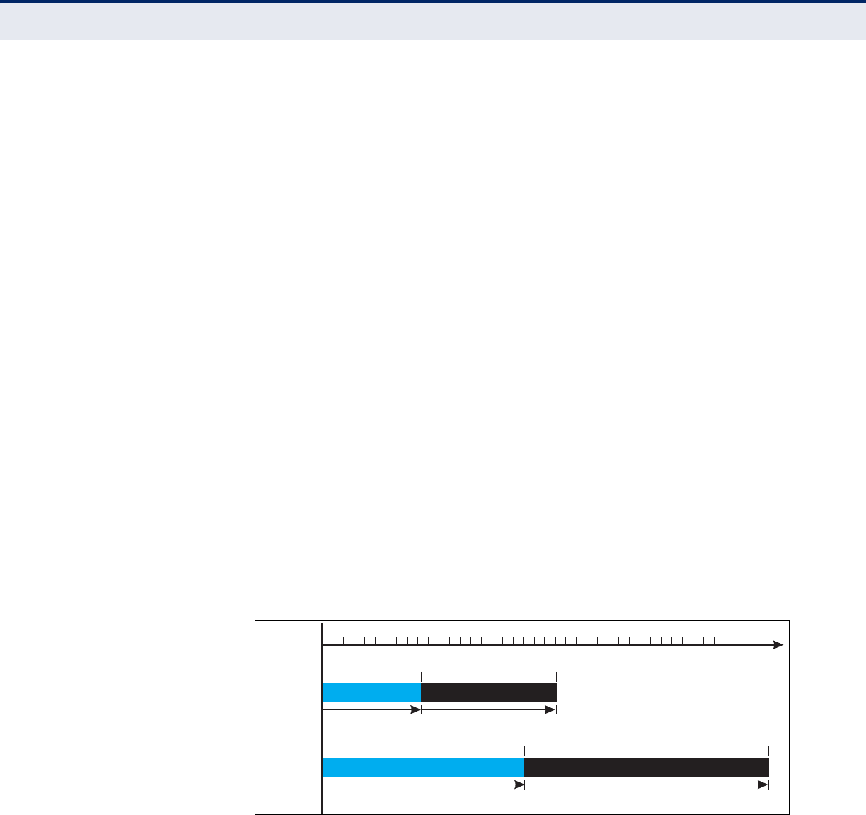
C
HAPTER
8
| Wireless Settings
QoS
– 100 –
WMM Operation — WMM uses traffic priority based on the four ACs; Voice,
Video, Best Effort, and Background. The higher the AC priority, the higher
the probability that data is transmitted.
When the access point forwards traffic, WMM adds data packets to four
independent transmit queues, one for each AC, depending on the 802.1D
priority tag of the packet. Data packets without a priority tag are always
added to the Best Effort AC queue. From the four queues, an internal
“virtual” collision resolution mechanism first selects data with the highest
priority to be granted a transmit opportunity. Then the same collision
resolution mechanism is used externally to determine which device has
access to the wireless medium.
For each AC queue, the collision resolution mechanism is dependent on two
timing parameters:
◆AIFSN (Arbitration Inter-Frame Space Number), a number used to
calculate the minimum time between data frames
◆CW (Contention Window), a number used to calculate a random backoff
time
After a collision detection, a backoff wait time is calculated. The total wait
time is the sum of a minimum wait time (Arbitration Inter-Frame Space, or
AIFS) determined from the AIFSN, and a random backoff time calculated
from a value selected from zero to the CW. The CW value varies within a
configurable range. It starts at CWMin and doubles after every collision up
to a maximum value, CWMax. After a successful transmission, the CW
value is reset to its CWMin value.
Figure 51: WMM Backoff Wait Times
For high-priority traffic, the AIFSN and CW values are smaller. The smaller
values equate to less backoff and wait time, and therefore more transmit
opportunities.
AIFS Random Backoff
AIFS Random Backoff
CWMin CWMax
CWMin CWMax
Time
High Priority
Low Priority
Minimum Wait Time Random Wait Time
Minimum Wait Time Random Wait Time
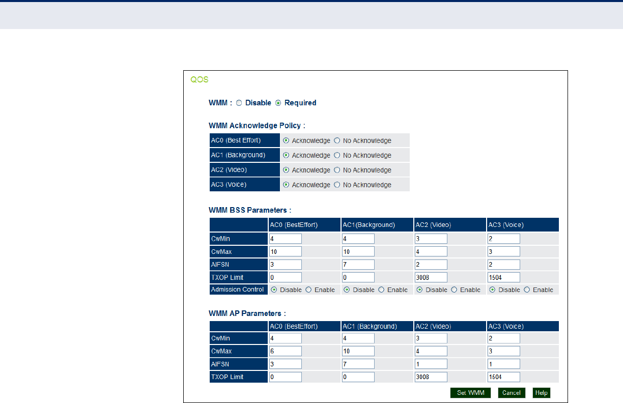
C
HAPTER
8
| Wireless Settings
QoS
– 101 –
Figure 52: QoS
The following items are displayed on this page:
◆WMM — Sets the WMM operational mode on the access point. When
enabled, the parameters for each AC queue will be employed on the
access point and QoS capabilities are advertised to WMM-enabled
clients. (Default: Support)
■Disable: WMM is disabled.
■Required: WMM must be supported on any device trying to
associated with the access point. Devices that do not support this
feature will not be allowed to associate with the access point.
◆WMM Acknowledge Policy — By default, all wireless data
transmissions require the sender to wait for an acknowledgement from
the receiver. WMM allows the acknowledgement wait time to be turned
off for each Access Category (AC) 0-3. Although this increases data
throughput, it can also result in a high number of errors when traffic
levels are heavy. (Default: Acknowledge)
■Aknowledge — Applies the WMM policy.
■No Aknowledge — Ignores the WMM policy.

C
HAPTER
8
| Wireless Settings
QoS
– 102 –
◆WMM BSS Parameters — These parameters apply to the wireless
clients.
◆WMM AP Parameters — These parameters apply to the access point.
■logCWMin (Minimum Contention Window): The initial upper limit of
the random backoff wait time before wireless medium access can be
attempted. The initial wait time is a random value between zero and
the CWMin value. Specify the CWMin value in the range 0-15
microseconds. Note that the CWMin value must be equal or less
than the CWMax value.
■logCWMax (Maximum Contention Window): The maximum upper
limit of the random backoff wait time before wireless medium
access can be attempted. The contention window is doubled after
each detected collision up to the CWMax value. Specify the CWMax
value in the range 0-15 microseconds. Note that the CWMax value
must be greater or equal to the CWMin value.
■AIFSN (Arbitration Inter-Frame Space): The minimum amount of
wait time before the next data transmission attempt. Specify the
AIFS value in the range 0-15 microseconds.
■TXOP Limit (Transmit Opportunity Limit): The maximum time an
AC transmit queue has access to the wireless medium. When an AC
queue is granted a transmit opportunity, it can transmit data for a
time up to the TxOpLimit. This data bursting greatly improves the
efficiency for high data-rate traffic. Specify a value in the range 0-
65535 microseconds.
■Admission Control: The admission control mode for the access
category. When enabled, clients are blocked from using the access
category. (Default: Disabled)
◆Set WMM — Applies the new parameters and saves them to RAM
memory. Also prompts a screen to inform you when it has taken affect.
Clicking ‘OK’ returns to the home page. Changes will not be saved upon
a reboot unless the running configuration file is saved.

– 103 –
9MAINTENANCE SETTINGS
Maintenance settings includes the following sections:
◆“Upgrading Firmware” on page 103
◆“Running Configuration” on page 106
◆“Resetting the Access Point” on page 107
UPGRADING FIRMWARE
You can upgrade new access point software from a local file on the
management workstation, or from an FTP or TFTP server. New software
may be provided periodically from your distributor.
After upgrading new software, you must reboot the access point to
implement the new code. Until a reboot occurs, the access point will
continue to run the software it was using before the upgrade started. Also
note that new software that is incompatible with the current configuration
automatically restores the access point to the factory default settings when
first activated after a reboot.
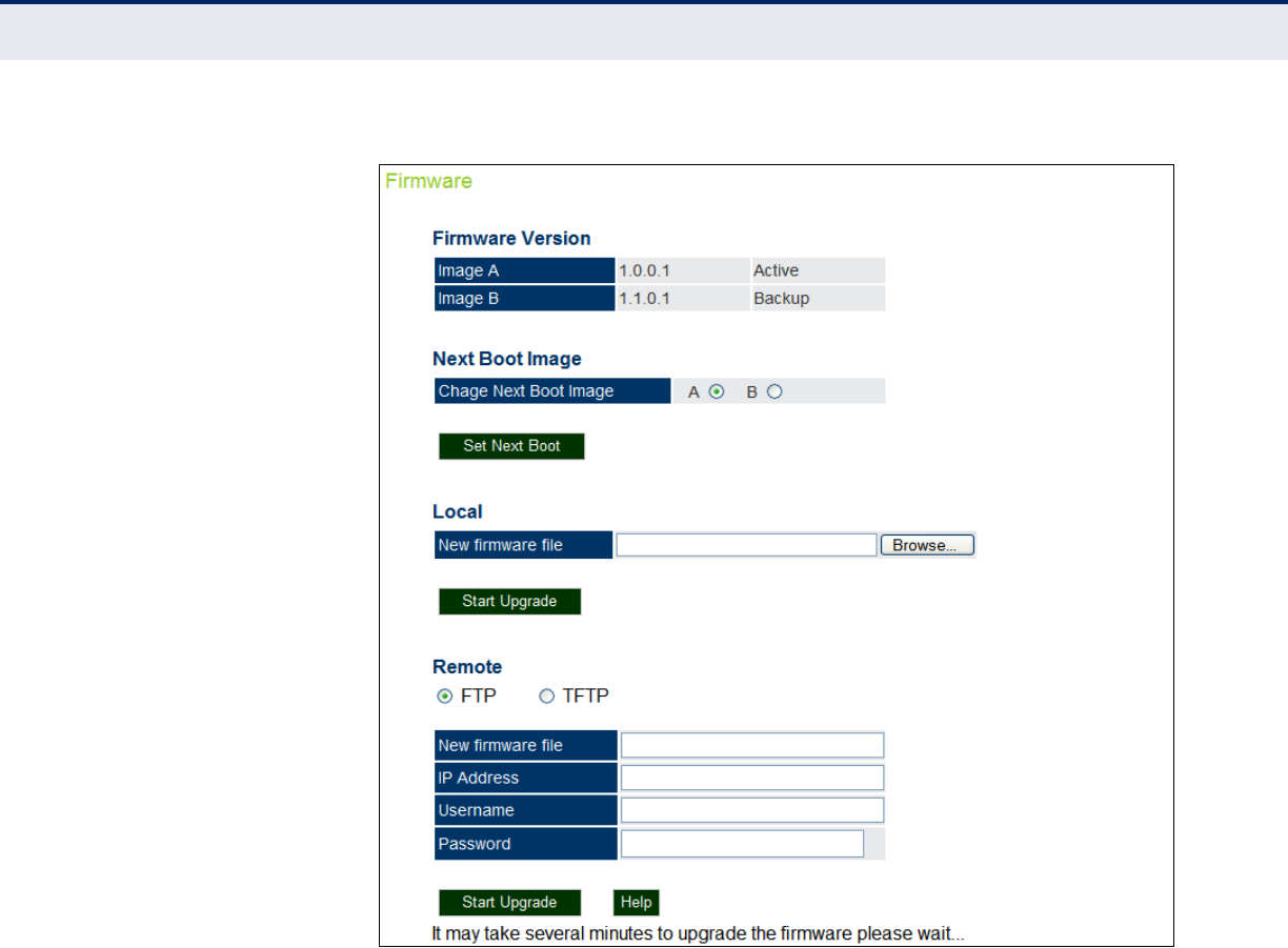
C
HAPTER
9
| Maintenance Settings
Upgrading Firmware
– 104 –
Figure 53: Firmware
The following items are displayed on this page:
◆Firmware Version — Displays what version of software is being used
as a runtime image - “Active”, and what version is a backup image -
“Backup”. You may specify up to two images.
◆Next Boot Image — Specifies what version of firmware will be used as
a runtime image upon bootup.
◆Set Next Boot — Applies the runtime image setting.
◆Local — Downloads an operation code image file from the web
management station to the access point using HTTP. Use the Browse
button to locate the image file locally on the management station and
click Start Upgrade to proceed.
■New Firmware File: Specifies the name of the code file on the
server. The new firmware file name should not contain slashes (\ or
/), the leading letter of the file name should not be a period (.), and

C
HAPTER
9
| Maintenance Settings
Upgrading Firmware
– 105 –
the maximum length for file names is 32 characters for files on the
access point. (Valid characters: A-Z, a-z, 0-9, “.”, “-”, “_”)
◆Remote — Downloads an operation code image file from a specified
remote FTP or TFTP server. After filling in the following fields, click Start
Upgrade to proceed.
■New Firmware File: Specifies the name of the code file on the
server. The new firmware file name should not contain slashes (\ or
/), the leading letter of the file name should not be a period (.), and
the maximum length for file names on the FTP/TFTP server is 255
characters or 32 characters for files on the access point. (Valid
characters: A-Z, a-z, 0-9, “.”, “-”, “_”)
■IP Address: IP address or host name of FTP or TFTP server.
■Username: The user ID used for login on an FTP server.
■Password: The password used for login on an FTP server.
◆Start Upgrade — Commences the upgrade process.
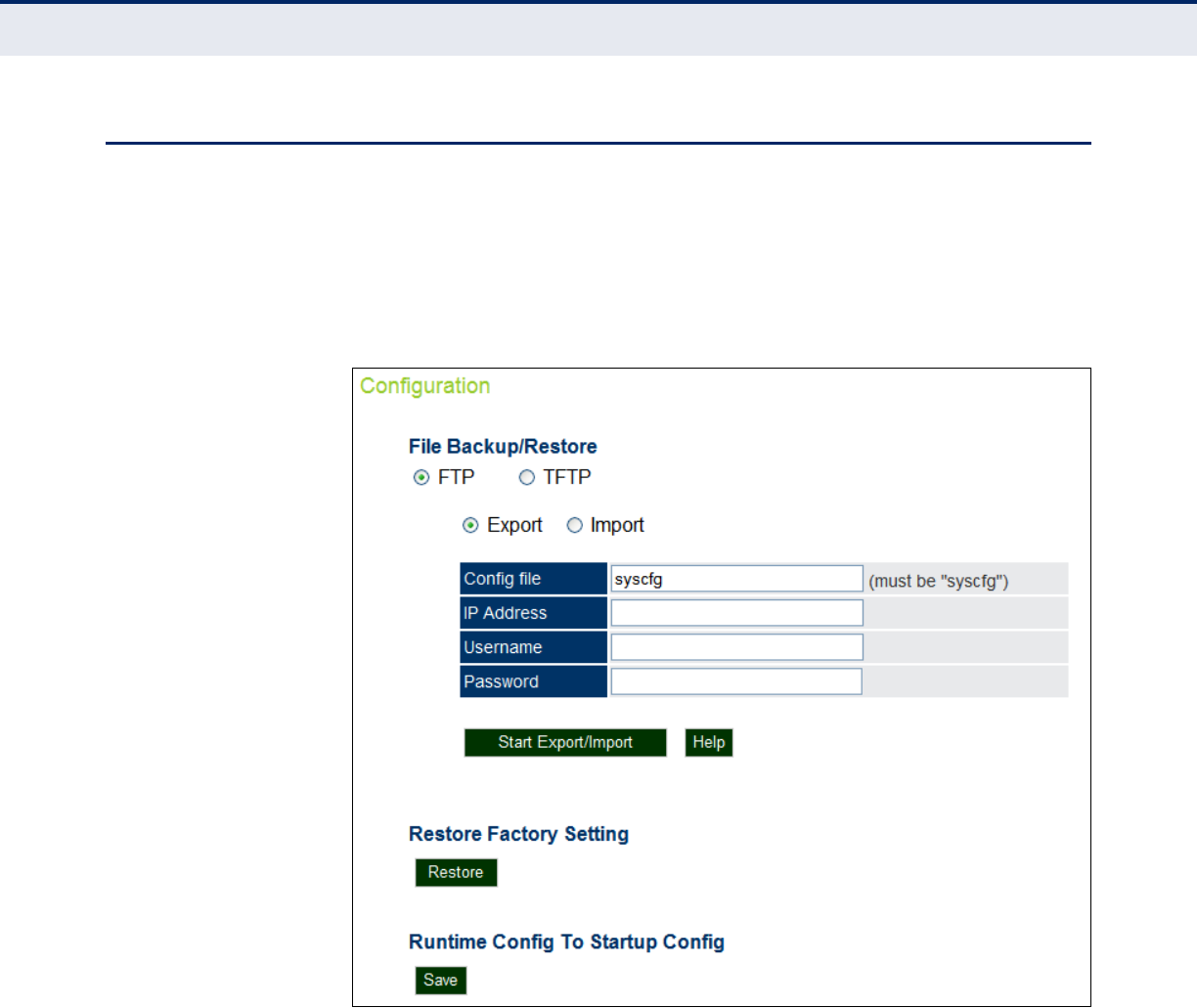
C
HAPTER
9
| Maintenance Settings
Running Configuration
– 106 –
RUNNING CONFIGURATION
A copy of a previous running configuration may be uploaded to the access
point as a saved file from a remote location, or the current configuration
saved and stored for restoration purposes at a later point. A configuration
file may be saved or downloaded to/from a specified remote FTP or TFTP
server.
Figure 54: Running Configuration File
The following items are displayed on this page:
◆File Backup/Restore — Downloads an operation code image file from
a specified remote FTP or TFTP server. After filling in the following
fields, click Start Export/Import to proceed.
◆Export/Import — Select Export to upload a file to an FTP/TFTP server.
Select Import to download a file from an FTP/TFTP server.
◆Config file — Specifies the name of the configuration file, which must
always be "syscfg." A path on the server can be specified using “/” in
the name, providing the path already exists; for example, “myfolder/
syscfg.” Other than to indicate a path, the file name must not contain
any slashes (\ or /), the leading letter cannot be a period (.), and the
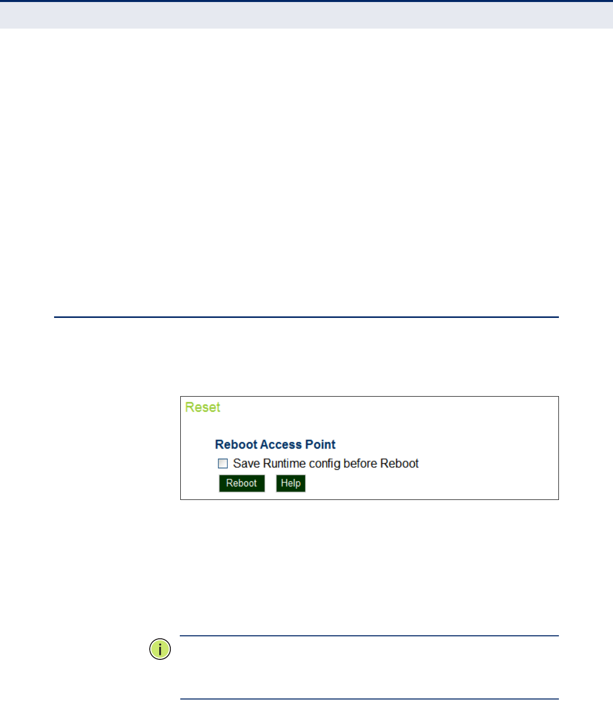
C
HAPTER
9
| Maintenance Settings
Resetting the Access Point
– 107 –
maximum length for file names on the FTP/TFTP server is 255
characters. (Valid characters: A-Z, a-z, 0-9, “.”, “-”, “_”)
◆IP Address — IP address or host name of FTP or TFTP server.
◆Username — The user ID used for login on an FTP server.
◆Password — The password used for login on an FTP server.
◆Start Import/Export — Initiates the selected backup or restore.
◆Restore Factory Setting — Click the Restore button to reset the
configuration settings for the access point to the factory defaults and
reboot the system. Note that all user configured information will be
lost. You will have to re-enter the default user name (admin) to re-gain
management access to this device.
◆Running Config To Startup Config — Clicking “Save” to save the
running configuration to the startup file.
RESETTING THE ACCESS POINT
The Reset page allows you to reset the access point and save the running
configuration before the reboot.
Figure 55: Resetting the Access Point
The following items are displayed on this page:
◆Save Runtime config before Reboot — Checking this option saves
the current running configuration to the startup file.
◆Reboot — Click the “Reboot” button to reset the configuration settings
for the access point and reboot the system. Note that all unsaved user
configured information will be lost. You will have to re-enter the default
user name (admin) to re-gain management access to this device.
N
OTE
:
If you have upgraded system software, then you must reboot the
access point to implement the new operation code. New software that is
incompatible with the current configuration automatically restores the
access point to default values when first activated after a reboot.

C
HAPTER
9
| Maintenance Settings
Resetting the Access Point
– 108 –

– 109 –
10 STATUS INFORMATION
The Information menu displays information on the current system
configuration, the wireless interface, the station status and system logs.
Status Information includes the following sections:
◆“AP Status” on page 109
◆“Station Status” on page 112
◆“System Logs” on page 112
AP STATUS
The AP Status window displays basic system configuration settings, as well
as the settings for the wireless interface.
AP SYSTEM
CONFIGURATION
The AP System Configuration table displays the basic system configuration
settings
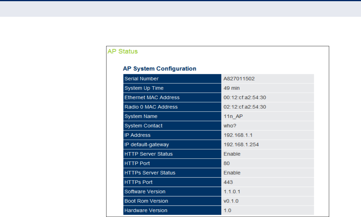
C
HAPTER
10
| Status Information
AP Status
– 110 –
Figure 56: AP System Configuration
The following items are displayed on this page:
◆Serial Number — The serial number of the physical access point.
◆System Up Time — Length of time the management agent has been
up.
◆Ethernet MAC Address — The physical layer address for the Ethernet
port.
◆Radio 0 MAC Address — The physical layer address for the VAP 0
interface.
◆System Name — Name assigned to this system.
◆System Contact — Administrator responsible for the system.
◆IP Address — IP address of the management interface for this device.
◆IP Default Gateway — IP address of the gateway router between this
device and management stations that exist on other network
segments.
◆HTTP Server Status — Shows if management access via HTTP is
enabled.
◆HTTP Port — Shows the TCP port used by the HTTP interface.
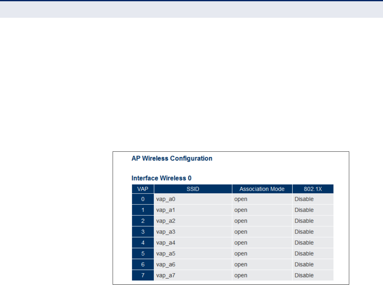
C
HAPTER
10
| Status Information
AP Status
– 111 –
◆HTTPS Server Status — Shows if management access via HTTPS is
enabled.
◆HTTPS Port — Shows the TCP port used by the HTTPS interface.
◆Software Version — Shows the software version number.
◆Bootrom Version — Show the bootrom version number.
◆Hardware Version — Shows the hardware version number.
AP WIRELESS
CONFIGURATION
The AP Wireless Configuration displays the VAP interface settings.
Figure 57: AP Wireless Configuration
The following items are displayed on this page:
◆VAP — Displays the VAP number.
◆SSID — The service set identifier for the VAP interface.
◆Association Mode — Shows the basic security mode configured for
the VAP.
◆802.1X — Shows if IEEE 802.1X access control for wireless clients is
enabled.
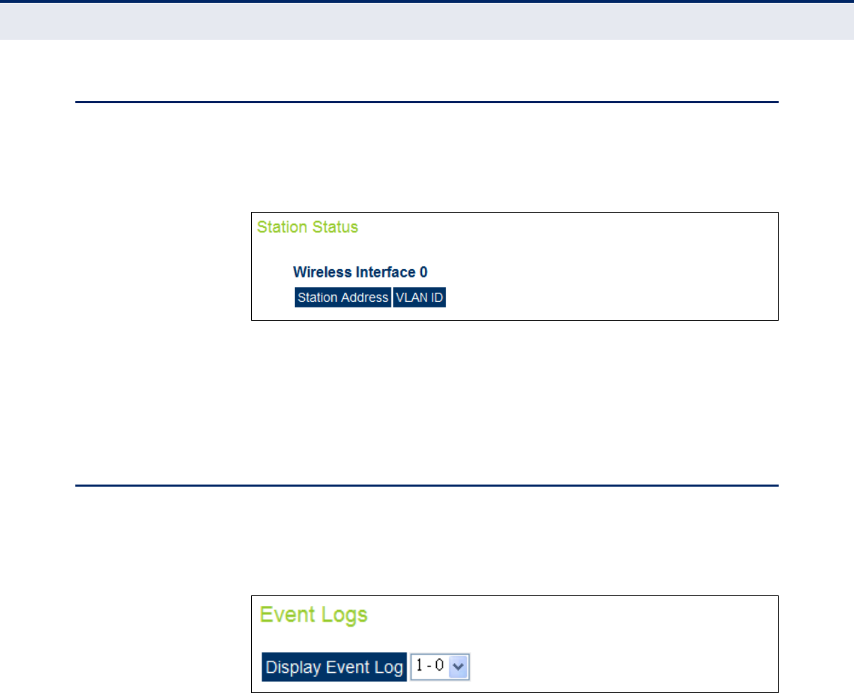
C
HAPTER
10
| Status Information
Station Status
– 112 –
STATION STATUS
The Station Status window shows the wireless clients currently associated
with the access point.
Figure 58: Station Status
The following items are displayed on this page:
◆Station Address — The MAC address of the wireless client.
◆VLAN ID — Displays the VLAN to which the wireless client has been
assigned.
SYSTEM LOGS
The Event Logs window shows the log messages generated by the access
point and stored in memory.
Figure 59: System Logs
The following items are displayed on this page:
◆Display Event Log — Chooses the logging level to display.
◆Log Time — The time the log message was generated.
◆Event Level — The logging level associated with this message.
◆Event Message — The content of the log message.

C
HAPTER
10
| Status Information
System Logs
– 113 –

– 114 –
S
ECTION
III
COMMAND LINE INTERFACE
This section provides a detailed description of the Command Line Interface,
along with examples for all of the commands.
This section includes these chapters:
◆“Using the Command Line Interface” on page 116
◆“General Commands” on page 122
◆“System Management Commands” on page 127
◆“System Logging Commands” on page 143
◆“System Clock Commands” on page 148
◆“DHCP Relay Commands” on page 152
◆“SNMP Commands” on page 154
◆“Flash/File Commands” on page 167
◆“RADIUS Client Commands” on page 170
◆“802.1X Authentication Commands” on page 175
◆“MAC Address Authentication Commands” on page 177
◆“Filtering Commands” on page 181
◆“WDS Bridge Commands” on page 193
◆“Spanning Tree Commands” on page 186
◆“Ethernet Interface Commands” on page 195
◆“Wireless Interface Commands” on page 201
◆“Rogue AP Detection Commands” on page 231
◆“Wireless Security Commands” on page 218


– 116 –
11 USING THE COMMAND LINE
INTERFACE
When accessing the management interface for the over a direct connection
to the console port, or via a Telnet connection, the access point can be
managed by entering command keywords and parameters at the prompt.
Using the access point’s command-line interface (CLI) is very similar to
entering commands on a UNIX system.
CONSOLE CONNECTION
To access the access point through the console port, perform these steps:
At the console prompt, enter the user name and password. (The default
user name is “admin” and the default password is “smcadmin”) When the
user name is entered, the CLI displays the “Enterprise AP#” prompt.
Enter the necessary commands to complete your desired tasks.
When finished, exit the session with the “exit” command.
After connecting to the system through the console port, the login screen
displays
EXAMPLE
(none) login: accton
Password:
1 03:47:41 login[2222]: root login on `ttyS0'
Accton#
N
OTE
:
Command examples shown later in this chapter abbreviate the
console prompt to “AP” for simplicity.

C
HAPTER
11
| Using the Command Line Interface
Telnet Connection
– 117 –
TELNET CONNECTION
Telnet operates over the IP transport protocol. In this environment, your
management station and any network device you want to manage over the
network must have a valid IP address. Valid IP addresses consist of four
numbers, 0 to 255, separated by periods. Each address consists of a
network portion and host portion. For example, if the access point cannot
acquire an IP address from a DHCP server, the default IP address used by
the access point, 192.168.1.1, consists of a network portion (192.168.1)
and a host portion (1).
To access the access point through a Telnet session, you must first set the
IP address for the access point, and set the default gateway if you are
managing the access point from a different IP subnet. For example:
AP#configure
AP(config)#interface ethernet
AP(if-ethernet)#ip address 10.1.0.1 255.255.255.0 10.1.0.254
AP(if-ethernet)#
If your corporate network is connected to another network outside your
office or to the Internet, you need to apply for a registered IP address.
However, if you are attached to an isolated network, then you can use any
IP address that matches the network segment to which you are attached.
After you configure the access point with an IP address, you can open a
Telnet session by performing these steps.
1. From the remote host, enter the Telnet command and the IP address of
the device you want to access.
2. At the prompt, enter the user name and system password. The CLI will
display the “Enterprise AP#” prompt to show that you are using
executive access mode (i.e., Exec).
3. Enter the necessary commands to complete your desired tasks.
4. When finished, exit the session with the “quit” or “exit” command.
After entering the Telnet command, the login screen displays:
Username: admin
Password:
Enterprise AP#
N
OTE
:
You can open up to four sessions to the device via Telnet.

C
HAPTER
11
| Using the Command Line Interface
Entering Commands
– 118 –
ENTERING COMMANDS
This section describes how to enter CLI commands.
KEYWORDS AND
ARGUMENTS
A CLI command is a series of keywords and arguments. Keywords identify
a command, and arguments specify configuration parameters. For
example, in the command “show interfaces ethernet,” show and
interfaces are keywords, and ethernet is an argument that specifies the
interface type.
You can enter commands as follows:
◆To enter a simple command, enter the command keyword.
◆To enter commands that require parameters, enter the required
parameters after the command keyword. For example, to set a
password for the administrator, enter:
Enterprise AP(config)#username smith
MINIMUM
ABBREVIATION
The CLI will accept a minimum number of characters that uniquely identify
a command. For example, the command “configure” can be entered as
con. If an entry is ambiguous, the system will prompt for further input.
COMMAND
COMPLETION
If you terminate input with a Tab key, the CLI will print the remaining
characters of a partial keyword up to the point of ambiguity. In the
“configure” example, typing con followed by a tab will result in printing the
command up to “configure.”
GETTING HELP ON
COMMANDS
You can display a brief description of the help system by entering the help
command. You can also display command syntax by following a command
with the “?” character to list keywords or parameters.
SHOWING COMMANDS If you enter a “?” at the command prompt, the system will display the first
level of keywords for the current configuration mode (Exec, Global
Configuration, or Interface). You can also display a list of valid keywords
for a specific command. For example, the command “show ?” displays a
list of possible show commands:
AP: show ?
APmanagement Show management AP information.
authentication Show Authentication parameters.
bridge Show bridge.
config Show current configuration.
event-log Show event log on console.
dual-image Show dual images version.
C
HAPTER
11
| Using the Command Line Interface
Entering Commands
– 119 –
filters Show filters.
interface Show interface information.
line TTY line information.
lldp Show lldp parameters.
logging Show the logging buffers.
radius Show radius server.
snmp Show snmp configuration.
sntp Show sntp configuration.
station Show 802.11 station table.
svp Show SVP.
system Show system information.
version Show system version.
wds Show WDS service.
AP: show
The command “show interface ?” will display the following information:
AP# show interface ?
ethernet Show Ethernet interface
wireless Show Wireless interface
AP# show interface
N
OTE
:
Partial keyword lookup does not work with the show command.
NEGATING THE EFFECT
OF COMMANDS
For many configuration commands you can enter the prefix keyword “no”
to cancel the effect of a command or reset the configuration to the default
value. For example, the logging command will log system messages to a
host server. To disable logging, specify the no logging command. This
guide describes the negation effect for all applicable commands.
USING COMMAND
HISTORY
The CLI maintains a history of commands that have been entered. You can
scroll back through the history of commands by pressing the up arrow key.
Any command displayed in the history list can be executed again, or first
modified and then executed.
Using the show history command displays a longer list of recently
executed commands.
UNDERSTANDING
COMMAND MODES
The command set is divided into Exec and Configuration classes. Exec
commands generally display information on system status or clear
statistical counters. Configuration commands, on the other hand, modify
interface parameters or enable certain functions. These classes are further
divided into different modes. Available commands depend on the selected
mode. You can always enter a question mark “?” at the prompt to display a

C
HAPTER
11
| Using the Command Line Interface
Entering Commands
– 120 –
list of the commands available for the current mode. The command classes
and associated modes are displayed in the following table:
EXEC COMMANDS When you open a new console session on an access point, the system
enters Exec command mode. Only a limited number of the commands are
available in this mode. You can access all other commands only from the
configuration mode. To access Exec mode, open a new console session with
the user name “admin.” The command prompt displays as “Enterprise AP#”
for Exec mode.
Username: admin
Password: [system login password]
AP#
CONFIGURATION
COMMANDS
Configuration commands are used to modify access point settings. These
commands modify the running configuration and are saved in memory.
The configuration commands are organized into four different modes:
◆Global Configuration (GC) - These commands modify the system level
configuration, and include commands such as username and
password.
◆Interface-Ethernet Configuration (IC-E) - These commands modify the
Ethernet port configuration, and include command such as dns and ip.
◆Interface-Wireless Configuration (IC-W) - These commands modify the
wireless port configuration of global parameters for the radio, and
include commands such as channel and transmit-power.
◆Interface-Wireless Virtual Access Point Configuration (IC-W-VAP) -
These commands modify the wireless port configuration for each VAP,
and include commands such as ssid and authentication.
To enter the Global Configuration mode, enter the command configure in
Exec mode. The system prompt will change to “Enterprise AP(config)#”
which gives you access privilege to all Global Configuration commands.
AP#configure
AP(config)#
Table 6: Command Modes
Class Mode
Exec Privileged
Configuration Global
Interface-ethernet
Interface-wireless
Interface-wireless-vap

C
HAPTER
11
| Using the Command Line Interface
Entering Commands
– 121 –
To enter Interface mode, you must enter the “interface ethernet” while
in Global Configuration mode. The system prompt will change to
“AP(if-ethernet)#,” or “AP(if-wireless)” indicating that you have access
privileges to the associated commands. You can use the end command to
return to the Exec mode.
AP(config)#interface ethernet
AP(if-ethernet)#
COMMAND LINE
PROCESSING
Commands are not case sensitive. You can abbreviate commands and
parameters as long as they contain enough letters to differentiate them
from any other currently available commands or parameters. You can use
the Tab key to complete partial commands, or enter a partial command
followed by the “?” character to display a list of possible matches. You can
also use the following editing keystrokes for command-line processing:
Table 7: Keystroke Commands
Keystroke Function
Ctrl-A Shifts cursor to start of command line.
Ctrl-B Shifts cursor to the left one character.
Ctrl-C Terminates a task and displays the command
prompt.
Ctrl-E Shifts cursor to end of command line.
Ctrl-F Shifts cursor to the right one character.
Ctrl-K Deletes from cursor to the end of the command line.
Ctrl-L Repeats current command line on a new line.
Ctrl-N Enters the next command line in the history buffer.
Ctrl-P Shows the last command.
Ctrl-R Repeats current command line on a new line.
Ctrl-U Deletes the entire line.
Ctrl-W Deletes the last word typed.
Esc-B Moves the cursor backward one word.
Esc-D Deletes from the cursor to the end of the word.
Esc-F Moves the cursor forward one word.
Delete key or
backspace key Erases a mistake when entering a command.

– 122 –
12 GENERAL COMMANDS
This chapter details general commands that apply to the CLI.
configure This command activates Global Configuration mode. You must enter this
mode to modify most of the settings on the access point. You must also
enter Global Configuration mode prior to enabling the context modes for
Interface Configuration. See “Using the Command Line Interface” on page
1.
DEFAULT SETTING
None
COMMAND MODE
Exec
EXAMPLE
AP#configure
AP(config)#
RELATED COMMANDS
end (123)
Table 8: General Commands
Command Function Mode Page
configure Activates global configuration mode Exec 122
end Returns to previous configuration mode GC, IC 123
exit Returns to the previous configuration mode, or exits
the CLI any 123
cli-session-timeout Enables, disbles or sets a timeout for the CLI or
Telnet session. Exec 123
ping Sends ICMP echo request packets to another node
on the network Exec 124
reset Restarts the system Exec 125
show history Shows the command history buffer Exec 125
show line Shows the configuration settings for the console port Exec 126

C
HAPTER
12
| General Commands
– 123 –
end This command returns to the previous configuration mode.
DEFAULT SETTING
None
COMMAND MODE
Global Configuration, Interface Configuration
EXAMPLE
This example shows how to return to the Configuration mode from the
Interface Configuration mode:
AP(if-ethernet)#end
AP(config)#
exit This command returns to the Exec mode or exits the configuration
program.
DEFAULT SETTING
None
COMMAND MODE
Any
EXAMPLE
This example shows how to return to the Exec mode from the Interface
Configuration mode, and then quit the CLI session:
AP(if-ethernet)#exit
AP#exit
CLI session with the Access Point is now closed
Username:
cli-session-timeout This command enables a timeout on the current and subsequent CLI or
Telnet sessions.
SYNTAX
cli-session-timeout <enable | disable | value>
enable - Enables the default timeout.
disable - Disables the timeout.
value - Sets a value for timeout (Range: 60~3600 seconds)
DEFAULT SETTING
120 seconds

C
HAPTER
12
| General Commands
– 124 –
COMMAND MODE
Exec
EXAMPLE
The following example disables the CLI/Telnet timeout.
AP(config)# cli-session-timeout disable
AP(config)#
ping This command sends ICMP echo request packets to another node on the
network.
SYNTAX
ping <host_name | ip_address>
host_name - Alias of the host.
ip_address - IP address of the host.
DEFAULT SETTING
None
COMMAND MODE
Exec
COMMAND USAGE
◆Use the ping command to see if another site on the network can be
reached.
◆The following are some results of the ping command:
■Normal response - The normal response occurs in one to ten
seconds, depending on network traffic.
■Destination does not respond - If the host does not respond, a
“timeout” appears in ten seconds.
■Destination unreachable - The gateway for this destination indicates
that the destination is unreachable.
■Network or host unreachable - The gateway found no corresponding
entry in the route table.
■Press <Esc> to stop pinging.
EXAMPLE
AP#ping 10.1.0.19
192.168.1.19 is alive
AP#

C
HAPTER
12
| General Commands
– 125 –
reset This command restarts the system or restores the factory default settings.
SYNTAX
reset <board | configuration>
board - Reboots the system.
configuration - Resets the configuration settings to the factory defaults,
and then reboots the system.
DEFAULT SETTING
None
COMMAND MODE
Exec
COMMAND USAGE
When the system is restarted, it will always run the Power-On Self-Test.
EXAMPLE
This example shows how to reset the system:
AP#reset board
Reboot system now? <y/n>: y
show history This command shows the contents of the command history buffer.
DEFAULT SETTING
None
COMMAND MODE
Exec
COMMAND USAGE
The history buffer size is fixed at 10 commands.
Use the up or down arrow keys to scroll through the commands in the
history buffer.
EXAMPLE
In this example, the show history command lists the contents of the
command history buffer:
AP#show history
config
exit
show history
AP#

C
HAPTER
12
| General Commands
– 126 –
show line This command displays the console port’s configuration settings.
COMMAND MODE
Exec
EXAMPLE
The console port settings are fixed at the values shown below.
AP#show line
Console Line Information
======================================================
databits : 8
parity : none
speed : 9600
stop bits : 1
======================================================
AP#

– 127 –
13 SYSTEM MANAGEMENT COMMANDS
SYSTEM MANAGEMENT COMMANDS
These commands are used to configure the user name, password, system
logs, browser management options, clock settings, and a variety of other
system information.
Table 9: System Management Commands
Command Function Mode Page
Country Setting
country Sets the access point country code Exec 128
Device Designation
prompt Customizes the command line prompt GC 129
system name Specifies the host name for the access point GC 130
Management Access
username Configures the user name for management access GC 130
password Specifies the password for management access GC 131
ip ssh-server enable Enables the Secure Shell server IC-E 131
ip ssh-server port Sets the Secure Shell port IC-E 132
ip telnet-server
enable Enables the Telnet server IC-E 132
APmgmtIP Specifies an IP address or range of addresses
allowed access to the management interface GC 135
APmgmtUI Enables or disables SNMP, Telnet or web
management access GC 136
show
APmanagement Shows the AP management configuration Exec 137
Web Server
ip http port Specifies the port to be used by the web browser
interface GC 133
ip http server Allows the access point to be monitored or
configured from a browser GC 133
ip https port Specifies the UDP port number used for a secure
HTTP connection to the access point’s Web interface GC 134
ip https server Enables the secure HTTP server on the access point GC 134
System Status
show system Displays system information Exec 137
show version Displays version information for the system Exec 138

C
HAPTER
13
| System Management Commands
System Management Commands
– 128 –
country This command configures the access point’s country code, which identifies
the country of operation and sets the authorized radio channels.
SYNTAX
country <country_code>
country_code - A two character code that identifies the country of
operation. See the following table for a full list of codes.
show config Displays detailed configuration information for the
system Exec 138
show hardware Displays the access point’s hardware version Exec 142
Table 9: System Management Commands (Continued)
Command Function Mode Page
Table 10: Country Codes
Country Code Country Code Country Code Country Code
Albania AL Dominican
Republic DO Kuwait KW Romania RO
Algeria DZ Ecuador EC Latvia LV Russia RU
Argentina AR Egypt EG Lebanon LB Saudi Arabia SA
Armenia AM Estonia EE Liechtenstein LI Singapore SG
Australia AU Finland FI Lithuania LT Slovak
Republic SK
Austria AT France FR Macao MO Spain ES
Azerbaijan AZ Georgia GE Macedonia MK Sweden SE
Bahrain BH Germany DE Malaysia MY Switzerland CH
Belarus BY Greece GR Malta MT Syria SY
Belgium BE Guatemala GT Mexico MX Taiwan TW
Honduras HN Monaco MC Thailand TH
Belize BZ Hong Kong HK Morocco MA Trinidad &
Tobago TT
Bolivia BO Hungary HU Netherlands NL Tunisia TN
Brazil BR Iceland IS New Zealand NZ Turkey TR
Brunei
Darussalam BN India IN Norway NO Ukraine UA
Bulgaria BG Indonesia ID Qatar QA United Arab
Emirates AE
Canada CA Iran IR Oman OM United
Kingdom GB
Chile CL Ireland IE Pakistan PK United States US
China CN Israel IL Panama PA Uruguay UY
Colombia CO Italy IT Peru PE Uzbekistan UZ
Costa Rica CR Japan JP Philippines PH Yemen YE
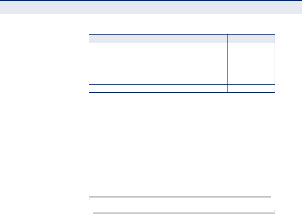
C
HAPTER
13
| System Management Commands
System Management Commands
– 129 –
DEFAULT SETTING
US - for units sold in the United States
99 (no country set) - for units sold in other countries
COMMAND MODE
Exec
COMMAND USAGE
◆If you purchased an access point outside of the United States, the
country code must be set before radio functions are enabled.
◆The available Country Code settings can be displayed by using the
country ? command.
EXAMPLE
AP#country tw
AP#
prompt This command customizes the CLI prompt. Use the no form to restore the
default prompt.
SYNTAX
prompt <string>
no prompt
string - Any alphanumeric string to use for the CLI prompt.
(Maximum length: 32 characters)
Croatia HR Jordan JO Poland PL Venezuela VE
Cyprus CY Kazakhstan KZ Portugal PT Vietnam VN
Czech
Republic CZ North Korea KP Puerto Rico PR Zimbabwe ZW
Denmark DK Korea
Republic KR Slovenia SI
Elsalvador SV Luxembourg LU South Africa ZA
Table 10: Country Codes (Continued)
Country Code Country Code Country Code Country Code

C
HAPTER
13
| System Management Commands
System Management Commands
– 130 –
DEFAULT SETTING
Enterprise AP
COMMAND MODE
Global Configuration
EXAMPLE
AP(config)#prompt RD2
RD2(config)#
system name This command specifies or modifies the system name for this device. Use
the no form to restore the default system name.
SYNTAX
system name <name>
no system name
name - The name of this host.
(Maximum length: 32 characters)
DEFAULT SETTING
Enterprise AP
COMMAND MODE
Global Configuration
EXAMPLE
AP(config)#system name AP
AP(config)#
username This command configures the user name for management access.
SYNTAX
username <name>
name - The name of the user.
(Length: 3-16 characters, case sensitive)

C
HAPTER
13
| System Management Commands
System Management Commands
– 131 –
DEFAULT SETTING
admin
COMMAND MODE
Global Configuration
EXAMPLE
AP(config)#username bob
AP(config)#
password After initially logging onto the system, you should set the password.
Remember to record it in a safe place. Use the no form to reset the default
password.
SYNTAX
password <password>
no password
password - Password for management access.
(Length: 3-16 characters, case sensitive)
DEFAULT SETTING
smcadmin
COMMAND MODE
Global Configuration
EXAMPLE
AP(config)#password
AP(config)#
ip ssh-server enable This command enables the Secure Shell server. Use the no form to disable
the server.
SYNTAX
ip ssh-server enable
no ip ssh-server
DEFAULT SETTING
Interface enabled
COMMAND MODE
Interface Configuration (Ethernet)
COMMAND USAGE
◆The access point supports Secure Shell version 2.0 only.

C
HAPTER
13
| System Management Commands
System Management Commands
– 132 –
◆After boot up, the SSH server needs about two minutes to generate
host encryption keys. The SSH server is disabled while the keys are
being generated. The show system command displays the status of
the SSH server.
EXAMPLE
AP(if-ethernet)#ip ssh-server enable
AP(if-ethernet)#
ip ssh-server port This command sets the Secure Shell server port. Use the no form to
disable the server.
SYNTAX
ip ssh-server port <port-number>
port-number - The UDP port used by the SSH server. (Range: 1-
65535)
DEFAULT SETTING
22
COMMAND MODE
Interface Configuration (Ethernet)
EXAMPLE
AP(if-ethernet)#ip ssh-server port 1124
AP(if-ethernet)#
ip telnet-server
enable
This command enables the Telnet server. Use the no form to disable the
server.
SYNTAX
ip telnet-server enable
no ip telnet-server
DEFAULT SETTING
Interface enabled
COMMAND MODE
Interface Configuration (Ethernet)
EXAMPLE
AP(if-ethernet)#ip telnet-server enable
AP(if-ethernet)#

C
HAPTER
13
| System Management Commands
System Management Commands
– 133 –
ip http port This command specifies the TCP port number used by the web browser
interface. Use the no form to use the default port.
SYNTAX
ip http port <port-number>
no ip http port
port-number - The TCP port to be used by the browser interface.
(Range: 1024-65535)
DEFAULT SETTING
80
COMMAND MODE
Global Configuration
EXAMPLE
AP(config)#ip http port 769
AP(config)
RELATED COMMANDS
ip http server (133)
ip http server This command allows this device to be monitored or configured from a
browser. Use the no form to disable this function.
SYNTAX
ip http server
no ip http server
DEFAULT SETTING
Enabled
COMMAND MODE
Global Configuration
EXAMPLE
AP(config)#ip http server
AP(config)#
RELATED COMMANDS
ip http port (133)

C
HAPTER
13
| System Management Commands
System Management Commands
– 134 –
ip https port Use this command to specify the UDP port number used for HTTPS/SSL
connection to the access point’s Web interface. Use the no form to restore
the default port.
SYNTAX
ip https port <port_number>
no ip https port
port_number – The UDP port used for HTTPS/SSL.
(Range: 80, 1024-65535)
DEFAULT SETTING
443
COMMAND MODE
Global Configuration
COMMAND USAGE
◆You cannot configure the HTTP and HTTPS servers to use the same
port.
◆To avoid using common reserved TCP port numbers below 1024, the
configurable range is restricted to 443 and between 1024 and 65535.
◆If you change the HTTPS port number, clients attempting to connect to
the HTTPS server must specify the port number in the URL, in this
format:
https://device:port_number
EXAMPLE
AP(config)#ip https port 1234
AP(config)#
ip https server Use this command to enable the secure hypertext transfer protocol
(HTTPS) over the Secure Socket Layer (SSL), providing secure access (i.e.,
an encrypted connection) to the access point’s Web interface. Use the no
form to disable this function.
SYNTAX
ip https server
no ip https server
DEFAULT SETTING
Enabled
COMMAND MODE
Global Configuration

C
HAPTER
13
| System Management Commands
System Management Commands
– 135 –
COMMAND USAGE
◆Both HTTP and HTTPS service can be enabled independently.
◆If you enable HTTPS, you must indicate this in the URL:
https://device:port_number]
◆When you start HTTPS, the connection is established in this way:
◆The client authenticates the server using the server’s digital certificate.
◆The client and server negotiate a set of security protocols to use for the
connection.
◆The client and server generate session keys for encrypting and
decrypting data.
◆The client and server establish a secure encrypted connection.
A padlock icon should appear in the status bar for Internet Explorer 5.x.
EXAMPLE
AP(config)#ip https server
AP(config)#
APmgmtIP This command specifies the client IP addresses that are allowed
management access to the access point through various protocols.
N
OTE
:
Secure Web (HTTPS) connections are not affected by the UI
Management or IP Management settings.
SYNTAX
APmgmtIP <multiple IP_address subnet_mask | single IP_address |
any>
multiple - Adds IP addresses within a specifiable range to the
SNMP, web and Telnet groups.
single - Adds an IP address to the SNMP, web and Telnet groups.
any - Allows any IP address access through SNMP, web and Telnet
groups.
IP_address - Adds IP addresses to the SNMP, web and Telnet
groups.
subnet_mask - Specifies a range of IP addresses allowed
management access.
DEFAULT SETTING
All addresses

C
HAPTER
13
| System Management Commands
System Management Commands
– 136 –
COMMAND MODE
Global Configuration
COMMAND USAGE
◆If anyone tries to access a management interface on the access point
from an invalid address, the unit will reject the connection, enter an
event message in the system log, and send a trap message to the trap
manager.
◆IP address can be configured for SNMP, web and Telnet access
respectively. Each of these groups can include up to five different sets
of addresses, either individual addresses or address ranges.
◆When entering addresses for the same group (i.e., SNMP, web or
Telnet), the access point will not accept overlapping address ranges.
When entering addresses for different groups, the access point will
accept overlapping address ranges.
◆You cannot delete an individual address from a specified range. You
must delete the entire range, and reenter the addresses.
◆You can delete an address range just by specifying the start address, or
by specifying both the start address and end address.
EXAMPLE
This example restricts management access to the indicated addresses.
AP(config)#apmgmtip multiple 192.168.1.50 255.255.255.0
AP(config)#
APmgmtUI This command enables and disables management access to the access
point through SNMP, Telnet and web interfaces.
C
AUTION
:
Secure Web (HTTPS) connections are not affected by the UI
Management or IP Management settings.
SYNTAX
APmgmtUI <[SNMP | Telnet | Web] enable | disable>
SNMP - Specifies SNMP management access.
Telnet - Specifies Telnet management access.
Web - Specifies web based management access.
enable/disable - Enables or disables the selected management
access method.

C
HAPTER
13
| System Management Commands
System Management Commands
– 137 –
DEFAULT SETTING
All enabled
COMMAND MODE
Global Configuration
EXAMPLE
This example restricts management access to the indicated addresses.
AP(config)#apmgmtui SNMP enable
AP(config)#
show
apmanagement
This command shows the AP management configuration, including the IP
addresses of management stations allowed to access the access point, as
well as the interface protocols which are open to management access.
COMMAND MODE
Exec
EXAMPLE
AP#show apmanagement
Management AP Information
=================================
AP Management IP Mode: Any IP
Telnet UI: Enable
WEB UI : Enable
SNMP UI : Enable
==================================
AP#
show system This command displays basic system configuration settings.
DEFAULT SETTING
None
COMMAND MODE
Exec
EXAMPLE
AP#show system
System Information
==========================================================
Serial Number : A123456789
System Up time : 0 days, 4 hours, 33 minutes, 29 seconds
System Name : SMC
System Location :
System Contact :

C
HAPTER
13
| System Management Commands
System Management Commands
– 138 –
System Country Code : US - UNITED STATES
MAC Address : 00-30-F1-F0-9A-9C
IP Address : 192.168.1.1
Subnet Mask : 255.255.255.0
Default Gateway : 0.0.0.0
VLAN State : DISABLED
Management VLAN ID(AP): 1
IAPP State : ENABLED
DHCP Client : ENABLED
HTTP Server : ENABLED
HTTP Server Port : 80
HTTPS Server : ENABLED
HTTPS Server Port : 443
Slot Status : Dual band(a/g)
Boot Rom Version : v3.0.3
Software Version : v4.3.1.9
SSH Server : ENABLED
SSH Server Port : 22
Telnet Server : ENABLED
WEB Redirect : DISABLED
DHCP Relay : DISABLED
Proxy ARP : DISABLED
==========================================================
AP#
show version This command displays the software version for the system.
COMMAND MODE
Exec
EXAMPLE
AP#show version
Version Information
=========================================
Version: v4.3.2.2
Date : Dec 20 2005, 18:38:12
=========================================
AP#
show config This command displays detailed configuration information for the system.
COMMAND MODE
Exec
EXAMPLE
AP#show config
Authentication Information
===========================================================
MAC Authentication Server : DISABLED
MAC Auth Session Timeout Value : 0 min
802.1x supplicant : DISABLED

C
HAPTER
13
| System Management Commands
System Management Commands
– 139 –
802.1x supplicant user : EMPTY
802.1x supplicant password : EMPTY
Address Filtering : ALLOWED
System Default : ALLOW addresses not found in filter table.
Filter Table
-----------------------------------------------------------
No Filter Entries.
Bootfile Information
===================================
Bootfile : ec-img.bin
===================================
Protocol Filter Information
===========================================================
Local Bridge :DISABLED
AP Management :ENABLED
Ethernet Type Filter :DISABLED
Enabled Protocol Filters
-----------------------------------------------------------
No protocol filters are enabled
===========================================================
Hardware Version Information
===========================================
Hardware version R01A
===========================================
Ethernet Interface Information
========================================
IP Address : 192.168.0.151
Subnet Mask : 255.255.255.0
Default Gateway : 192.168.0.1
Primary DNS : 210.200.211.225
Secondary DNS : 210.200.211.193
Speed-duplex : 100Base-TX Full Duplex
Admin status : Up
Operational status : Up
========================================
Wireless Interface 802.11a Information
===========================================================
----------------Identification-----------------------------
Description : SMC 802.11a Access Point
SSID : SMC_A 0
Channel : 0 (AUTO)
Status : Disable
----------------802.11 Parameters--------------------------
Transmit Power : 100% (5 dBm)
Data Rate : 54Mbps
Fragmentation Threshold : 2346 bytes
RTS Threshold : 2347 bytes
Beacon Interval : 100 TUs
DTIM Interval : 1 beacon
Maximum Association : 64 stations
Native VLAN ID : 1
----------------Security-----------------------------------
Closed System : DISABLED
Multicast cipher : WEP
Unicast cipher : TKIP and AES
WPA clients : REQUIRED
WPA Key Mgmt Mode : PRE SHARED KEY
WPA PSK Key Type : ALPHANUMERIC
Encryption : DISABLED

C
HAPTER
13
| System Management Commands
System Management Commands
– 140 –
Default Transmit Key : 1
Static Keys :
Key 1: EMPTY Key 2: EMPTY Key 3: EMPTY Key 4: EMPTY
Key Length :
Key 1: ZERO Key 2: ZERO Key 3: ZERO Key 4: ZERO
Authentication Type : OPEN
Rogue AP Detection : Disabled
Rogue AP Scan Interval : 720 minutes
Rogue AP Scan Duration : 350 milliseconds
===========================================================
Console Line Information
===========================================================
databits : 8
parity : none
speed : 9600
stop bits : 1
===========================================================
Logging Information
=====================================================
Syslog State : Disabled
Logging Console State : Disabled
Logging Level : Informational
Logging Facility Type : 16
Servers
1: 0.0.0.0 , UDP Port: 514, State: Disabled
2: 0.0.0.0 , UDP Port: 514, State: Disabled
3: 0.0.0.0 , UDP Port: 514, State: Disabled
4: 0.0.0.0 , UDP Port: 514, State: Disabled
======================================================
Radius Server Information
========================================
IP : 0.0.0.0
Port : 1812
Key : *****
Retransmit : 3
Timeout : 5
Radius MAC format : no-delimiter
Radius VLAN format : HEX
========================================
Radius Secondary Server Information
========================================
IP : 0.0.0.0
Port : 1812
Key : *****
Retransmit : 3
Timeout : 5
Radius MAC format : no-delimiter
Radius VLAN format : HEX
========================================
SNMP Information
==============================================
Service State : Disable
Community (ro) : ********
Community (rw) : ********
Location :
Contact : Contact
EngineId :80:00:07:e5:80:00:00:29:f6:00:00:00:0c
EngineBoots:2

C
HAPTER
13
| System Management Commands
System Management Commands
– 141 –
Trap Destinations:
1: 0.0.0.0, Community: *****, State: Disabled
2: 0.0.0.0, Community: *****, State: Disabled
3: 0.0.0.0, Community: *****, State: Disabled
4: 0.0.0.0, Community: *****, State: Disabled
dot11InterfaceAGFail Enabled dot11InterfaceBFail Enabled
dot11StationAssociation Enabled dot11StationAuthentication Enabled
dot11StationReAssociation Enabled dot11StationRequestFail Enabled
dot1xAuthFail Enabled dot1xAuthNotInitiated Enabled
dot1xAuthSuccess Enabled dot1xMacAddrAuthFail Enabled
dot1xMacAddrAuthSuccess Enabled iappContextDataSent Enabled
iappStationRoamedFrom Enabled iappStationRoamedTo Enabled
localMacAddrAuthFail Enabled localMacAddrAuthSuccess Enabled
pppLogonFail Enabled sntpServerFail Enabled
configFileVersionChanged Enabled radiusServerChanged Enabled
systemDown Enabled systemUp Enabled
=============================================
SNTP Information
===========================================================
Service State : Disabled
SNTP (server 1) IP : 137.92.140.80
SNTP (server 2) IP : 192.43.244.18
Current Time : 00 : 14, Jan 1st, 1970
Time Zone : -5 (BOGOTA, EASTERN, INDIANA)
Daylight Saving : Disabled
===========================================================
Station Table Information
===========================================================
if-wireless A VAP [0] :
802.11a Channel : Auto
No 802.11a Channel Stations.
.
.
.
if-wireless G VAP [0] :
802.11g Channel : Auto
No 802.11g Channel Stations.
.
.
.
System Information
==============================================================
Serial Number :
System Up time : 0 days, 0 hours, 16 minutes, 51 seconds
System Name : SMC
System Location :
System Contact : Contact
System Country Code : 99 - NO_COUNTRY_SET
MAC Address : 00-12-CF-05-B7-84
IP Address : 192.168.0.151
Subnet Mask : 255.255.255.0
Default Gateway : 192.168.0.1
VLAN State : DISABLED
Management VLAN ID(AP): 1
IAPP State : ENABLED
DHCP Client : ENABLED
HTTP Server : ENABLED
HTTP Server Port : 80
HTTPS Server : ENABLED

C
HAPTER
13
| System Management Commands
System Management Commands
– 142 –
HTTPS Server Port : 443
Slot Status : Dual band(a/g)
Boot Rom Version : v3.0.7
Software Version : v4.3.2.2
SSH Server : ENABLED
SSH Server Port : 22
Telnet Server : ENABLED
WEB Redirect : DISABLED
DHCP Relay : DISABLED
==============================================================
Version Information
=========================================
Version: v4.3.2.2
Date : Dec 20 2005, 18:38:12
=========================================
AP#
show hardware This command displays the hardware version of the system.
COMMAND MODE
Exec
EXAMPLE
AP#show hardware
Hardware Version Information
===========================================
Hardware version R01
===========================================
AP#

– 143 –
14 SYSTEM LOGGING COMMANDS
These commands are used to configure system logging on the access
point.
logging on This command controls logging of error messages; i.e., sending debug or
error messages to memory. The no form disables the logging process.
SYNTAX
[no] logging on
DEFAULT SETTING
Disabled
COMMAND MODE
Global Configuration
COMMAND USAGE
The logging process controls error messages saved to memory. You can
use the logging level command to control the type of error messages that
are stored in memory.
EXAMPLE
AP(config)#logging on
AP(config)#
Table 11: System Management Commands
Command Function Mode Page
logging on Controls logging of error messages GC 143
logging host Adds a syslog server host IP address that will receive
logging messages GC 144
logging console Initiates logging of error messages to the console GC 144
logging level Defines the minimum severity level for event logging GC 145
logging facility-type Sets the facility type for remote logging of syslog
messages GC 145
logging clear Clears all log entries in access point memory GC 146
show logging Displays the state of logging Exec 146
show event-log Displays all log entries in access point memory Exec 147

C
HAPTER
14
| System Logging Commands
– 144 –
logging host This command specifies syslog servers host that will receive logging
messages. Use the no form to remove syslog server host.
SYNTAX
logging host <1 | 2 | 3 | 4> <host_name | host_ip_address>
[udp_port]
no logging host <1 | 2 | 3 | 4>
1 - First syslog server.
2 - Second syslog server.
3 - Third syslog server.
4 - Fourth syslog server.
host_name - The name of a syslog server. (Range: 1-20 characters)
host_ip_address - The IP address of a syslog server.
udp_port - The UDP port used by the syslog server.
DEFAULT SETTING
None
COMMAND MODE
Global Configuration
EXAMPLE
AP(config)#logging host 1 10.1.0.3
AP(config)#
logging console This command initiates logging of error messages to the console. Use the
no form to disable logging to the console.
SYNTAX
logging console
no logging console
DEFAULT SETTING
Disabled
COMMAND MODE
Global Configuration
EXAMPLE
AP(config)#logging console
AP(config)#

C
HAPTER
14
| System Logging Commands
– 145 –
logging level This command sets the minimum severity level for event logging.
SYNTAX
logging level <Emergency | Alert | Critical | Error | Warning |
Notice | Informational | Debug>
DEFAULT SETTING
Informational
COMMAND MODE
Global Configuration
COMMAND USAGE
Messages sent include the selected level down to Emergency level.
EXAMPLE
AP(config)#logging level alert
AP(config)#
logging facility-type This command sets the facility type for remote logging of syslog messages.
SYNTAX
logging facility-type <type>
type - A number that indicates the facility used by the syslog server
to dispatch log messages to an appropriate service. (Range: 16-23)
DEFAULT SETTING
16
COMMAND MODE
Global Configuration
Table 12: Logging Levels
Level Argument Description
Emergency System unusable
Alert Immediate action needed
Critical Critical conditions (e.g., memory allocation, or free
memory error - resource exhausted)
Error Error conditions (e.g., invalid input, default used)
Warning Warning conditions (e.g., return false, unexpected
return)
Notice Normal but significant condition, such as cold start
Informational Informational messages only
Debug Debugging messages

C
HAPTER
14
| System Logging Commands
– 146 –
COMMAND USAGE
The command specifies the facility type tag sent in syslog messages. (See
RFC 3164.) This type has no effect on the kind of messages reported by
the access point. However, it may be used by the syslog server to sort
messages or to store messages in the corresponding database.
EXAMPLE
AP(config)#logging facility 19
AP(config)#
logging clear This command clears all log messages stored in the access point’s memory.
SYNTAX
logging clear
COMMAND MODE
Global Configuration
EXAMPLE
AP(config)#logging clear
AP(config)#
show logging This command displays the logging configuration.
SYNTAX
show logging
COMMAND MODE
Exec
EXAMPLE
AP#show logging
Logging Information
============================================
Syslog State : Enabled
Logging Console State : Enabled
Logging Level : Alert
Logging Facility Type : 16
Servers
1: 192.168.1.19, UDP Port: 514, State: Enabled
2: 0.0.0.0, UDP Port: 514, State: Disabled
3: 0.0.0.0, UDP Port: 514, State: Disabled
4: 0.0.0.0, UDP Port: 514, State: Disabled
=============================================
AP#

C
HAPTER
14
| System Logging Commands
– 147 –
show event-log This command displays log messages stored in the access point’s memory.
SYNTAX
show event-log
COMMAND MODE
Exec
EXAMPLE
AP#show event-log
Mar 09 11:57:55 Information: 802.11g:11g Radio Interface Enabled
Mar 09 11:57:55 Information: 802.11g:Radio channel updated to 8
Mar 09 11:57:34 Information: 802.11g:11g Radio Interface Enabled
Mar 09 11:57:18 Information: 802.11g:11g Radio Interface Enabled
Mar 09 11:56:35 Information: 802.11a:11a Radio Interface Enabled
Mar 09 11:55:52 Information: SSH task: Set SSH server port to 22
Mar 09 11:55:52 Information: SSH task: Enable SSH server.
Mar 09 11:55:52 Information: Enable Telnet.
Mar 09 11:55:40 Information: 802.11a:11a Radio Interface Disabled
Mar 09 11:55:40 Information: 802.11a:Transmit Power set to QUARTER
Press <n> next. <p> previous. <a> abort. <y> continue to end :
AP#configure
Enter configuration commands, one per line. End with CTRL/Z
AP(config)#logging clear

– 148 –
15 SYSTEM CLOCK COMMANDS
These commands are used to configure SNTP and system clock settings on
the access point.
sntp-server ip This command sets the IP address of the servers to which SNTP time
requests are issued. Use the this command with no arguments to clear all
time servers from the current list.
SYNTAX
sntp-server ip <1 | 2> <ip>
1 - First time server.
2 - Second time server.
ip - IP address of an time server (NTP or SNTP).
DEFAULT SETTING
137.92.140.80
192.43.244.18
COMMAND MODE
Global Configuration
COMMAND USAGE
When SNTP client mode is enabled using the sntp-server enable
command, the sntp-server ip command specifies the time servers from
which the access point polls for time updates. The access point will poll the
time servers in the order specified until a response is received.
Table 13: System Clock Commands
Command Function Mode Page
sntp-server ip Specifies one or more time servers GC 148
sntp-server
enable Accepts time from the specified time
servers GC 149
sntp-server
date-time Manually sets the system date and time GC 149
sntp-server
daylight-saving Sets the start and end dates for daylight
savings time GC 150
sntp-server
timezone Sets the time zone for the access point’s
internal clock GC 150
show sntp Shows current SNTP configuration
settings Exec 151

C
HAPTER
15
| System Clock Commands
– 149 –
EXAMPLE
AP(config)#sntp-server ip 10.1.0.19
AP#
RELATED COMMANDS
sntp-server enable (149)
show sntp (151)
sntp-server enable This command enables SNTP client requests for time synchronization with
NTP or SNTP time servers specified by the sntp-server ip command. Use
the no form to disable SNTP client requests.
SYNTAX
sntp-server enable
no sntp-server enable
DEFAULT SETTING
Enabled
COMMAND MODE
Global Configuration
COMMAND USAGE
The time acquired from time servers is used to record accurate dates and
times for log events. Without SNTP, the access point only records the time
starting from the factory default set at the last bootup (i.e., 00:14:00,
January 1, 1970).
EXAMPLE
AP(config)#sntp-server enable
AP(config)#
RELATED COMMANDS
sntp-server ip (148)
show sntp (151)
sntp-server date-
time
This command sets the system clock.
DEFAULT SETTING
00:14:00, January 1, 1970
COMMAND MODE
Global Configuration
EXAMPLE
This example sets the system clock to 17:37 June 19, 2003.

C
HAPTER
15
| System Clock Commands
– 150 –
AP#sntp-server date-time
Enter Year<1970-2100>: 2003
Enter Month<1-12>: 6
Enter Day<1-31>: 19
Enter Hour<0-23>: 17
Enter Min<0-59>: 37
AP#
RELATED COMMANDS
sntp-server enable (149)
sntp-server
daylight-saving
This command sets the start and end dates for daylight savings time. Use
the no form to disable daylight savings time.
SYNTAX
sntp-server daylight-saving
no sntp-server daylight-saving
DEFAULT SETTING
Disabled
COMMAND MODE
Global Configuration
COMMAND USAGE
The command sets the system clock back one hour during the specified
period.
EXAMPLE
This sets daylight savings time to be used from July 1st to September 1st.
AP(config)#sntp-server daylight-saving
Enter Daylight saving from which month<1-12>: 6
and which day<1-31>: 1
Enter Daylight saving end to which month<1-12>: 9
and which day<1-31>: 1
AP(config)#
sntp-server
timezone
This command sets the time zone for the access point’s internal clock.
SYNTAX
sntp-server timezone <hours>
hours - Number of hours before/after UTC.
(Range: -12 to +12 hours)

C
HAPTER
15
| System Clock Commands
– 151 –
DEFAULT SETTING
-5 (BOGOTA, EASTERN, INDIANA)
COMMAND MODE
Global Configuration
COMMAND USAGE
This command sets the local time zone relative to the Coordinated
Universal Time (UTC, formerly Greenwich Mean Time or GMT), based on
the earth’s prime meridian, zero degrees longitude. To display a time
corresponding to your local time, you must indicate the number of hours
and minutes your time zone is east (before) or west (after) of UTC.
EXAMPLE
AP(config)#sntp-server timezone +8
AP(config)#
show sntp This command displays the current time and configuration settings for the
SNTP client.
COMMAND MODE
Exec
EXAMPLE
AP#show sntp
SNTP Information
=========================================================
Service State : Enabled
SNTP (server 1) IP : 137.92.140.80
SNTP (server 2) IP : 192.43.244.18
Current Time : 08 : 04, Jun 20th, 2003
Time Zone : +8 (TAIPEI, BEIJING)
Daylight Saving : Enabled, from Jun, 1st to Sep, 1st
=========================================================
AP#

– 152 –
16 DHCP RELAY COMMANDS
Dynamic Host Configuration Protocol (DHCP) can dynamically allocate an
IP address and other configuration information to network clients that
broadcast a request. To receive the broadcast request, the DHCP server
would normally have to be on the same subnet as the client. However,
when the access point’s DHCP relay agent is enabled, received client
requests can be forwarded directly by the access point to a known DHCP
server on another subnet. Responses from the DHCP server are returned to
the access point, which then broadcasts them back to clients.
dhcp-relay enable This command enables the access point’s DHCP relay agent. Use the no
form to disable the agent.
SYNTAX
[no] dhcp-relay enable
DEFAULT SETTING
Disabled
COMMAND MODE
Global Configuration
COMMAND USAGE
◆For the DHCP relay agent to function, the primary DHCP server must be
configured using the dhcp-relay primary command. A secondary
DHCP server does not need to be configured, but it is recommended.
◆If there is no response from the primary DHCP server, and a secondary
server has been configured, the agent will then attempt to send DHCP
requests to the secondary server.
Table 14: DHCP Relay Commands
Command Function Mode Page
dhcp-relay enable Enables the DHCP relay agent GC 152
dhcp-relay Sets the primary and secondary DHCP
server address GC 153
show dhcp-relay Shows current DHCP relay
configuration settings Exec 153

C
HAPTER
16
| DHCP Relay Commands
– 153 –
EXAMPLE
AP(config)#dhcp-relay enable
AP(config)#
dhcp-relay This command configures the primary and secondary DHCP server
addresses.
SYNTAX
dhcp-relay <primary | secondary> <ip_address>
primary - The primary DHCP server.
secondary - The secondary DHCP server.
ip_address - IP address of the server.
DEFAULT SETTING
Primary and secondary: 0.0.0.0
COMMAND MODE
Global Configuration
EXAMPLE
AP(config)#dhcp-relay primary 192.168.1.10
AP(config)#
show dhcp-relay This command displays the current DHCP relay configuration.
COMMAND MODE
Exec
EXAMPLE
AP#show dhcp-relay
DHCP Relay : ENABLED
Primary DHCP Server : 192.168.1.10
Secondary DHCP Server : 0.0.0.0
AP#

– 154 –
17 SNMP COMMANDS
Controls access to this access point from management stations using the
Simple Network Management Protocol (SNMP), as well as the hosts that
will receive trap messages.
snmp-server
community
This command defines the community access string for the Simple Network
Management Protocol. Use the no form to remove the specified community
string.
SYNTAX
snmp-server community string [ro | rw]
no snmp-server community string
string - Community string that acts like a password and permits
access to the SNMP protocol. (Maximum length: 23 characters, case
sensitive)
ro - Specifies read-only access. Authorized management stations
are only able to retrieve MIB objects.
rw - Specifies read/write access. Authorized management stations
are able to both retrieve and modify MIB objects.
Table 15: SNMP Commands
Command Function Mode Page
snmp-server community Sets up the community access string to permit
access to SNMP commands GC 154
snmp-server contact Sets the system contact string GC 155
snmp-server location Sets the system location string GC 155
snmp-server enable
server Enables SNMP service and traps GC 156
snmp-server host Specifies the recipient of an SNMP notification
operation GC 157
snmp-server trap Enables specific SNMP notifications GC 157
snmp-server user Sets the name of the SNMP v3 user GC 161
snmp-server targets Configures SNMP v3 notification targets GC 162
snmp-server filter Configures SNMP v3 notification filters GC 163
show snmp users Displays SNMP v3 user settings Exec 164
show snmp target Displays the SNMP v3 notification targets Exec 164
show snmp filter Displays the SNMP v3 notification filters Exec 165
show snmp Displays the status of SNMP communications Exec 165

C
HAPTER
17
| SNMP Commands
– 155 –
DEFAULT SETTING
◆public - Read-only access. Authorized management stations are only
able to retrieve MIB objects.
◆private - Read/write access. Authorized management stations are able
to both retrieve and modify MIB objects.
COMMAND MODE
Global Configuration
COMMAND USAGE
If you enter a community string without the ro or rw option, the default is
read only.
EXAMPLE
AP(config)#snmp-server community alpha rw
AP(config)#
snmp-server
contact
This command sets the system contact string. Use the no form to remove
the system contact information.
SYNTAX
snmp-server contact string
no snmp-server contact
string - String that describes the system contact.
(Maximum length: 255 characters)
DEFAULT SETTING
None
COMMAND MODE
Global Configuration
EXAMPLE
AP(config)#snmp-server contact Paul
AP(config)#
RELATED COMMANDS
snmp-server location (155)
snmp-server
location
This command sets the system location string. Use the no form to remove
the location string.

C
HAPTER
17
| SNMP Commands
– 156 –
SYNTAX
snmp-server location <text>
no snmp-server location
text - String that describes the system location.
(Maximum length: 255 characters)
DEFAULT SETTING
None
COMMAND MODE
Global Configuration
EXAMPLE
AP(config)#snmp-server location WC-19
AP(config)#
RELATED COMMANDS
snmp-server contact (155)
snmp-server enable
server
This command enables SNMP management access and also enables this
device to send SNMP traps (i.e., notifications). Use the no form to disable
SNMP service and trap messages.
SYNTAX
snmp-server enable server
no snmp-server enable server
DEFAULT SETTING
Enabled
COMMAND MODE
Global Configuration
COMMAND USAGE
◆This command enables both authentication failure notifications and
link-up-down notifications.
◆The snmp-server host command specifies the host device that will
receive SNMP notifications.
EXAMPLE
AP(config)#snmp-server enable server
AP(config)#

C
HAPTER
17
| SNMP Commands
– 157 –
RELATED COMMANDS
snmp-server host (157)
snmp-server host This command specifies the recipient of an SNMP notification. Use the no
form to remove the specified host.
SYNTAX
snmp-server host <host_ip_address> <community-string>
no snmp-server host
host_ip_address - IP of the host (the targeted recipient).
community-string - Password-like community string sent with the
notification operation. Although you can set this string using the
snmp-server host command by itself, we recommend that you
define this string using the snmp-server community command
prior to using the snmp-server host command. (Maximum length:
23 characters)
DEFAULT SETTING
Host Address: None
Community String: public
COMMAND MODE
Global Configuration
COMMAND USAGE
The snmp-server host command is used in conjunction with the snmp-
server enable server command to enable SNMP notifications. You can
configure up to four host IP addresses. A separate snmp-server host
command must be entered for each host.
EXAMPLE
AP(config)#snmp-server host 1 10.1.19.23 batman
AP(config)#
RELATED COMMANDS
snmp-server enable server (156)
snmp-server trap This command enables the access point to send specific SNMP traps
(i.e., notifications). Use the no form to disable specific trap messages.
SYNTAX
snmp-server trap <trap>
no snmp-server trap <trap>

C
HAPTER
17
| SNMP Commands
– 158 –
trap - One of the following SNMP trap messages:
dot11InterfaceAGFail - The 802.11a or 802.11g interface has
failed.
dot11InterfaceBFail - The 802.11b interface has failed.
dot11StationAssociation - A client station has successfully
associated with the access point.
dot11StationAuthentication - A client station has been
successfully authenticated.
dot11StationReAssociation - A client station has successfully
re-associated with the access point.
dot11StationRequestFail - A client station has failed
association, re-association, or authentication.
dot1xAuthFail - A 802.1X client station has failed RADIUS
authentication.
dot1xAuthNotInitiated - A client station did not initiate
802.1X authentication.
dot1xAuthSuccess - A 802.1X client station has been
successfully authenticated by the RADIUS server.
dot1xMacAddrAuthFail - A client station has failed MAC
address authentication with the RADIUS server.
dot1xMacAddrAuthSuccess - A client station has successfully
authenticated its MAC address with the RADIUS server.
iappContextDataSent - A client station’s Context Data has
been sent to another access point with which the station has
associated.
iappStationRoamedFrom - A client station has roamed from
another access point (identified by its IP address).
iappStationRoamedTo - A client station has roamed to
another access point (identified by its IP address).
localMacAddrAuthFail - A client station has failed
authentication with the local MAC address database on the
access point.
localMacAddrAuthSuccess - A client station has successfully
authenticated its MAC address with the local database on the
access point.
pppLogonFail - The access point has failed to log onto the
PPPoE server using the configured user name and password.
sntpServerFail - The access point has failed to set the time
from the configured SNTP server.
sysConfigFileVersionChanged - The access point’s
configuration file has been changed.
sysRadiusServerChanged - The access point has changed
from the primary RADIUS server to the secondary, or from the
secondary to the primary.

C
HAPTER
17
| SNMP Commands
– 159 –
sysSystemDown - The access point is about to shutdown and
reboot.
sysSystemUp - The access point is up and running.
DEFAULT SETTING
All traps enabled
COMMAND MODE
Global Configuration
COMMAND USAGE
This command is used in conjunction with the snmp-server host and
snmp-server enable server commands to enable SNMP notifications.
EXAMPLE
AP(config)#no snmp-server trap dot11StationAssociation
AP(config)#
snmp-server vacm
view
This command configures SNMP v3 vacm views. Use the no form to delete
an SNMP v3 view or remove a subtree from a filter.
SYNTAX
snmp-server vacm view <name> [included | excluded] <subtree>
[mask <mask>]
name - A user-defined name that identifies an SNMP v3 view.
(Maximum length: 32 characters)
include - Defines a filter type that includes objects in the MIB
subtree.
exclude - Defines a filter type that excludes objects in the MIB
subtree.
subtree - The part of the MIB subtree that is to be filtered.
mask - An optional hexadecimal value bit mask to define objects in
the MIB subtree.
DEFAULT SETTING
None
COMMAND MODE
Global Configuration
COMMAND USAGE
◆The access point allows up to 10 notification filters to be created. Each
filter can be defined by up to 20 MIB subtree ID entries.

C
HAPTER
17
| SNMP Commands
– 160 –
◆Use the command more than once with the same filter ID to build a
filter that includes or excludes multiple MIB objects. Note that the filter
entries are applied in the sequence that they are defined.
◆The MIB subtree must be defined in the form “.1.3.6.1” and always
start with a “.”.
◆The mask is a hexadecimal value with each bit masking the
corresponding ID in the MIB subtree. A “1” in the mask indicates an
exact match and a “0” indicates a “wild card.” For example, a mask
value of 0xFFBF provides a bit mask “1111 1111 1011 1111.” If applied
to the subtree 1.3.6.1.2.1.2.2.1.1.23, the zero corresponds to the 10th
subtree ID. When there are more subtree IDs than bits in the mask, the
mask is padded with ones.
EXAMPLE
AP(config)#snmp-server vacm view trapfilter include .1
AP(config)#snmp-server vacm view trapfilter exclude .1.3.6.1.2.1.2.2.1.1.23
snmp-server vacm
group
This command configures SNMP v3 vacm view group. Use the no form to
delete an SNMP v3 view group or remove a subtree from a filter.
SYNTAX
snmp-server vacm group <name> {security-level <level>}
<read-view> <write-view>
name - A user-defined name that identifies an SNMP v3 group.
(Maximum length: 32 characters)
level - The SNMPv3 security level of the group. One of the following:
NoAuthNoPriv - A group using no authentication and no data
encryption. Users in this group use no security, either
authentication or encryption, in SNMP messages they send to
the agent.
AuthNoPriv - A group using authentication, but no data
encryption. Users in this group send SNMP messages that use
an MD5 key/password for authentication, but not a DES key/
password for encryption.
AuthPriv - A group using authentication and data encryption.
Users in this group send SNMP messages that use an MD5 key/
password for authentication and a DES key/password for
encryption.
read-view - The name of a defined SNMPv3 view for read access.
write-view - The name of a defined SNMPv3 view for write access.
DEFAULT SETTING
None

C
HAPTER
17
| SNMP Commands
– 161 –
COMMAND MODE
Global Configuration
COMMAND USAGE
◆The access point allows up to 10 notification filters to be created. Each
filter can be defined by up to 20 MIB subtree ID entries.
◆Use the command more than once with the same filter ID to build a
filter that includes or excludes multiple MIB objects. Note that the filter
entries are applied in the sequence that they are defined.
◆The MIB subtree must be defined in the form “.1.3.6.1” and always
start with a “.”.
◆The mask is a hexadecimal value with each bit masking the
corresponding ID in the MIB subtree. A “1” in the mask indicates an
exact match and a “0” indicates a “wild card.” For example, a mask
value of 0xFFBF provides a bit mask “1111 1111 1011 1111.” If applied
to the subtree 1.3.6.1.2.1.2.2.1.1.23, the zero corresponds to the 10th
subtree ID. When there are more subtree IDs than bits in the mask, the
mask is padded with ones.
EXAMPLE
AP(config)#snmp-server vacm view trapfilter include .1
AP(config)#snmp-server vacm view trapfilter exclude .1.3.6.1.2.1.2.2.1.1.23
snmp-server user This command configures the SNMP v3 users that are allowed to manage
the access point. Use the no form to delete an SNMP v3 user.
SYNTAX
snmp-server user <username> <groupname> {none | md5 <auth-
passphrase>} {none | des <priv-passphrase>}
username - Name of the user connecting to the SNMP agent.
(Range: 1-32 characters)
groupname - Name of an SNMP group to which the user is assigned.
(Range: 1-32 characters)
none | md5 - Uses no authentication or MD5 authentication.
auth-passphrase - Authentication password. Enter a minimum of
eight characters for the user. (8 – 32 characters)
none | des - Uses SNMPv3 with no privacy, or with DES56
encryption.
priv-passphrase - Privacy password. Enter a minimum of eight
characters for the user. (8 – 32 characters)
DEFAULT SETTING
None

C
HAPTER
17
| SNMP Commands
– 162 –
COMMAND MODE
Global Configuration
COMMAND USAGE
◆Up to 10 SNMPv3 users can be configured on the access point.
◆The SNMP engine ID is used to compute the authentication/privacy
digests from the pass phrase. You should therefore configure the
engine ID with the snmp-server engine-id command before using
this configuration command.
◆Users must be assigned to groups that have the same security levels. If
a user who has “AuthPriv” security (uses authentication and
encryption) is assigned to a NoAuthNoPriv, the user will not be able to
access the database. An AuthPriv user must be assigned to the group
with the AuthPriv security level.
EXAMPLE
AP(config)#snmp-server user
User Name<1-32> :chris
Group Name<1-32> :RWPriv
Authtype(md5,<cr>none):md5
Passphrase<8-32>:a good secret
Privacy(des,<cr>none) :des
Passphrase<8-32>:a very good secret
AP(config)#
snmp-server targets This command configures SNMP v3 notification targets. Use the no form to
delete an SNMP v3 target.
SYNTAX
snmp-server targets <target-id> <ip-addr> <sec-name> udp-port
<port-number> [notification-filter-id]
no snmp-server targets <target-id>
target-id - A user-defined name that identifies a receiver of SNMP
notifications. (Maximum length: 32 characters)
ip-addr - Specifies the IP address of the management station to
receive notifications.
sec-name - The defined SNMP v3 user name that is to receive
notifications.
udp-port - The UDP port that is used on the receiving management
station for notifications.
notification-filter-id - The name if a defined notification filter.
DEFAULT SETTING
None

C
HAPTER
17
| SNMP Commands
– 163 –
COMMAND MODE
Global Configuration
COMMAND USAGE
◆The access point supports up to 10 SNMP v3 target IDs.
◆The SNMP v3 user name that is specified in the target must first be
configured using the snmp-server user command.
EXAMPLE
AP(config)#snmp-server targets mytraps 192.168.1.33 chris
AP(config)#
snmp-server filter This command configures SNMP v3 notification filters. Use the no form to
delete an SNMP v3 filter or remove a subtree from a filter.
SYNTAX
snmp-server filter <filter-id> <include | exclude> <subtree>
no snmp-server filter <filter-id> [subtree]
filter-id - A user-defined name that identifies an SNMP v3
notification filter. (Maximum length: 32 characters)
include - Defines a filter type that includes objects in the MIB
subtree.
exclude - Defines a filter type that excludes objects in the MIB
subtree.
subtree - The part of the MIB subtree that is to be filtered.
DEFAULT SETTING
None
COMMAND MODE
Global Configuration
COMMAND USAGE
◆The access point allows up to 10 notification filters to be created. Each
filter can be defined by up to 20 MIB subtree ID entries.
◆Use the command more than once with the same filter ID to build a
filter that includes or excludes multiple MIB objects. Note that the filter
entries are applied in the sequence that they are defined.
◆The MIB subtree must be defined in the form “.1.3.6.1” and always
start with a “.”.

C
HAPTER
17
| SNMP Commands
– 164 –
EXAMPLE
AP(config)#snmp-server filter trapfilter include .1
AP(config)#snmp-server filter trapfilter exclude .1.3.6.1.2.1.2.2.1.1.23
show snmp users This command displays the SNMP v3 users and settings.
SYNTAX
show snmp users
COMMAND MODE
Exec
EXAMPLE
AP#show snmp users
=============================================
UserName :chris
GroupName :RWPriv
AuthType :MD5
Passphrase:****************
PrivType :DES
Passphrase:****************
=============================================
AP#
show snmp target This command displays the SNMP v3 notification target settings.
SYNTAX
show snmp target
COMMAND MODE
Exec
EXAMPLE
AP#show snmp target
Host ID : mytraps
User : chris
IP Address : 192.168.1.33
UDP Port : 162
=============================
AP#

C
HAPTER
17
| SNMP Commands
– 165 –
show snmp vacm
group / show snmp
vacm view
This command displays the SNMP v3 notification filter settings.
SYNTAX
show snmp filter [filter-id]
filter-id - A user-defined name that identifies an SNMP v3
notification filter. (Maximum length: 32 characters)
COMMAND MODE
Exec
EXAMPLE
AP#show snmp filter
Filter: trapfilter
Type: include
Subtree: iso.3.6.1.2.1.2.2.1
Type: exclude
Subtree: iso.3.6.1.2.1.2.2.1.1.23
=============================
AP#show snmp
This command displays the SNMP configuration settings.
COMMAND MODE
Exec
EXAMPLE
AP#show snmp
SNMP Information
==============================================
Service State : Enable
Community (ro) : *****
Community (rw) : *****
Location : WC-19
Contact : Paul
EngineId :80:00:07:e5:80:00:00:2e:62:00:00:00:18
EngineBoots:1
Trap Destinations:
1: 192.168.1.9, Community: *****, State: Enabled
2: 0.0.0.0, Community: *****, State: Disabled
3: 0.0.0.0, Community: *****, State: Disabled
4: 0.0.0.0, Community: *****, State: Disabled
dot11InterfaceAGFail Enabled dot11InterfaceBFail Enabled
dot11StationAssociation Enabled dot11StationAuthentication
Enabled
dot11StationReAssociation Enabled dot11StationRequestFail
Enabled
dot1xAuthFail Enabled dot1xAuthNotInitiated Enabled
dot1xAuthSuccess Enabled dot1xMacAddrAuthFail Enabled
dot1xMacAddrAuthSuccess Enabled iappContextDataSent
Enabled

C
HAPTER
17
| SNMP Commands
– 166 –
iappStationRoamedFrom Enabled iappStationRoamedTo
Enabled
localMacAddrAuthFail Enabled localMacAddrAuthSuccess Enabled
pppLogonFail Enabled sntpServerFail Enabled
configFileVersionChanged Enabled radiusServerChanged
Enabled
systemDown Enabled systemUp Enabled
=============================================
AP#

– 167 –
18 FLASH/FILE COMMANDS
These commands are used to manage the system code or configuration
files.
dual-image This command specifies the image used to start up the system.
SYNTAX
dual-image boot image [a | b]
a/b - Specifies the image file to be used as a primary startup file.
DEFAULT SETTING
None
COMMAND MODE
Exec
COMMAND USAGE
◆Specifies the name of the code file on the server. The new firmware file
name should not contain slashes (\ or /), the leading letter of the file
name should not be a period (.), and the maximum length for file
names is 32 characters for files on the access point. (Valid characters:
A-Z, a-z, 0-9, “.”, “-”, “_”)
◆If the file contains an error, it cannot be set as the default file.
EXAMPLE
AP# dual-image boot-image A
Change image to A
AP#
Table 16: Flash/File Commands
Command Function Mode Page
dual-image Specifies the file or image used to start up the
system GC 167
copy Copies a code image or configuration between
flash memory and a FTP/TFTP server Exec 168
show dual-image Displays the name of the current operation
code file that
booted the system
Exec 169

C
HAPTER
18
| Flash/File Commands
– 168 –
copy This command copies a boot file, code image, or configuration file between
the access point’s flash memory and a FTP/TFTP server. When you save the
configuration settings to a file on a FTP/TFTP server, that file can later be
downloaded to the access point to restore system operation. The success
of the file transfer depends on the accessibility of the FTP/TFTP server and
the quality of the network connection.
SYNTAX
copy {ftp [firmware | config] <file-name> <ip-address> <user-
name> <password> | tftp [firmware | config] <file-name> <ip-
address>}
copy config {ftp <file-name> <ip-address> <user-name>
<password> | tftp <file-name> <ip-address>}
copy running startup
ftp - Keyword that allows you to copy to/from an FTP server.
tftp - Keyword that allows you to copy to/from a TFTP server.
file - Keyword that allows you to copy to/from a flash memory file.
config - Keyword that allows you to upload the configuration file
from flash memory.
DEFAULT SETTING
None
COMMAND MODE
Exec
COMMAND USAGE
◆The system prompts for data required to complete the copy command.
◆Only a configuration file can be uploaded to an FTP/TFTP server, but
every type of file can be downloaded to the access point.
◆
The destination file name should not contain slashes (\ or /),
the leading
letter of the file name should not be a period (.), and the maximum
length for file names on the FTP/TFTP server is 255 characters or 32
characters for files on the access point. (Valid characters: A-Z, a-z, 0-9,
“.”, “-”, “_”)
◆Due to the size limit of the flash memory, the access point supports
only two operation code files.
◆The system configuration file must be named “syscfg” in all copy
commands.
EXAMPLE
The following example shows how to upload the configuration settings to a
file on the TFTP server:

C
HAPTER
18
| Flash/File Commands
– 169 –
AP#copy config tftp
TFTP Source file name:syscfg
TFTP Server IP:192.168.1.19
AP#
The following example shows how to download a configuration file:
AP#copy tftp file
1. Application image
2. Config file
3. Boot block image
Select the type of download<1,2,3>: [1]:2
TFTP Source file name:syscfg
TFTP Server IP:192.168.1.19
AP#
show dual-image This command displays the name of the current operation code file that
booted the system and the file saved as a secondary image.
SYNTAX
show snmp filter-assignments
COMMAND MODE
Exec
EXAMPLE
AP#show dual-image
Image Status Version
-----------------------------------------------
Image A (Active) 1.1.0.6
Image B (Backup) 1.1.0.1
AP#

– 170 –
19 RADIUS CLIENT COMMANDS
Remote Authentication Dial-in User Service (RADIUS) is a logon
authentication protocol that uses software running on a central server to
control access for RADIUS-aware devices to the network. An authentication
server contains a database of credentials, such as users names and
passwords, for each wireless client that requires access to the access point.
radius-server enable This command enables the RADIUS server.
SYNTAX
radius-server {primary | secondary} enable
primary - Specifies the primary RADIUS server.
secondary - Specifies the secondary RADIUS server.
DEFAULT SETTING
Disabled
COMMAND MODE
Global Configuration
EXAMPLE
AP(config)# radius-server primary enable
This setting has not been effective !
Table 17: RADIUS Client Commands
Command Function Mode Page
radius-server enable Enables the RADIUS server. GC 170
radius-server address Specifies the RADIUS server GC 171
radius-server port Sets the RADIUS server network port GC 171
radius-server key Sets the RADIUS encryption key GC 171
radius-server accounting
address Sets the RADIUS server accounting address GC 172
radius-server accounting
port Sets the RADIUS server accounting port GC 172
radius-server accounting
key Sets the RADIUS server accounting key GC 173
radius-server accounting
timeout-interim Sets the interval between transmitting
accounting updates to the RADIUS server GC 173
show radius Shows the current RADIUS settings Exec 174

C
HAPTER
19
| RADIUS Client Commands
– 171 –
If want to take effect, please execute make-radius-effective command !
AP(config)#
radius-server
address
This command specifies the primary and secondary RADIUS server
address.
SYNTAX
radius-server {primary | secondary} address <address>
address - IP address of server.
DEFAULT SETTING
None
COMMAND MODE
Global Configuration
EXAMPLE
AP(config)#radius-server address 192.168.1.25
AP(config)#
radius-server port This command sets the RADIUS server network port.
SYNTAX
radius-server {primary | secondary} port <port_number>
port_number - RADIUS server UDP port used for authentication
messages. (Range: 1024-65535)
DEFAULT SETTING
1812
COMMAND MODE
Global Configuration
EXAMPLE
AP(config)#radius-server secondary port 181
AP(config)#
radius-server key This command sets the RADIUS encryption key.
SYNTAX
radius-server {primary | secondary] key <key_string>

C
HAPTER
19
| RADIUS Client Commands
– 172 –
key_string - Encryption key used to authenticate logon access for
client. Do not use blank spaces in the string. (Maximum length: 20
characters)
DEFAULT SETTING
DEFAULT
COMMAND MODE
Global Configuration
EXAMPLE
AP(config)#radius-server primary key green
AP(config)#
radius-server
accounting-address
This command sets the RADIUS Accounting server network IP address.
SYNTAX
radius-server accounting-address <address>
address - IP address of the RADIUS Accounting server
DEFAULT SETTING
0 (disabled)
COMMAND MODE
Global Configuration
COMMAND USAGE
◆When the RADIUS Accounting server UDP address is specified, a
RADIUS accounting session is automatically started for each user that
is successfully authenticated to the access point.
EXAMPLE
AP(config)#radius-server accounting-address 192.168.2.5
AP(config)#
radius-server
accounting port
This command sets the RADIUS Accounting port.
SYNTAX
radius-server accounting port <port>
port - The port used by the RADIUS Accounting server.
(Range: 1024~65535)

C
HAPTER
19
| RADIUS Client Commands
– 173 –
DEFAULT SETTING
0 (disabled)
COMMAND MODE
Global Configuration
COMMAND USAGE
◆When the RADIUS Accounting server UDP port is specified, a RADIUS
accounting session is automatically started for each user that is
successfully authenticated to the access point.
EXAMPLE
AP(config)#radius-server accounting port 1024
AP(config)#
radius-server
accounting key
This command sets the RADIUS Accounting key.
SYNTAX
radius-server accounting key <key>
key - The RADIUS Accounting server keyphrase.
DEFAULT SETTING
0 (disabled)
COMMAND MODE
Global Configuration
EXAMPLE
AP(config)#radius-server accounting key green
AP(config)#
radius-server
accounting
timeout-interim
This command sets the interval between transmitting accounting updates
to the RADIUS server.
SYNTAX
radius-server {[primary | secondary] timeout-interim
<number_of_seconds>}
number_of_seconds - Number of seconds the access point waits
between transmitting accounting updates. (Range: 60-86400)
DEFAULT SETTING
3600

C
HAPTER
19
| RADIUS Client Commands
– 174 –
COMMAND MODE
Global Configuration
COMMAND USAGE
◆The access point sends periodic accounting updates after every interim
period until the user logs off and a “stop” message is sent.
EXAMPLE
AP(config)#radius-server timeout-interim 500
AP(config)#
show radius This command displays the current settings for the RADIUS server.
DEFAULT SETTING
None
COMMAND MODE
Exec
EXAMPLE
AP#show radius
Radius Accounting Information
==============================================
IP : 10.7.16.96
Key : *********
Port : 1813
timeout-interim : 300
==============================================
Radius Primary Server Information
==============================================
Status : ENABLED
IP : 192.168.1.1
Port : 1812
Key : *********
==============================================
Radius Secondary Server Information
==============================================
Status : ENABLED
IP : 10.7.16.96
Port : 1812
Key : ****
==============================================
AP#

– 175 –
20 802.1X AUTHENTICATION
COMMANDS
The access point supports IEEE 802.1X access control for wireless clients.
This control feature prevents unauthorized access to the network by
requiring an 802.1X client application to submit user credentials for
authentication. Client authentication is then verified by a RADIUS server
using EAP (Extensible Authentication Protocol) before the access point
grants client access to the network. The 802.1X EAP packets are also used
to pass dynamic unicast session keys and static broadcast keys to wireless
clients.
802.1x enable This command configures 802.1X as enabled for wireless clients. Use the
no form to disable 802.1X support.
SYNTAX
802.1x enable
no 802.1x
enable - Authenticates clients that initiate the 802.1X
authentication process. Uses standard 802.11 authentication for all
others.
DEFAULT SETTING
Disabled
COMMAND MODE
Global Configuration
COMMAND USAGE
◆When 802.1X is disabled, the access point does not support 802.1X
authentication for any station. After successful 802.11 association,
each client is allowed to access the network.
◆802.1X does not apply to the 10/100Base-TX port.
Table 18: 802.1x Authentication
Command Function Mode Page
802.1x enable Configures 802.1X as enabled or disabled IC-W-
VAP 175
802.1x session-
timeout Sets the timeout after which a connected client
must be re-authenticated IC-W-
VAP 176
show authentication Shows all 802.1X authentication settings, as
well as the address filter table Exec 176

C
HAPTER
20
| 802.1X Authentication Commands
– 176 –
EXAMPLE
AP(config)#802.1x enable
AP(config)#
802.1x session-
timeout
This command sets the time period after which a connected client must be
re-authenticated. Use the no form to disable 802.1X re-authentication.
SYNTAX
802.1x session-timeout <seconds>
seconds - The number of seconds. (Range: 0-65535)
DEFAULT
0 (Disabled)
COMMAND MODE
Global Configuration
EXAMPLE
AP(config)#802.1x session-timeout 300
AP(config)#
show authentication This command shows all 802.1X authentication settings, as well as the
address filter table.
COMMAND MODE
Exec
EXAMPLE
AP# show authentication
Authentication Information
===========================================================
MAC Authentication Server : Disable
Session Timeout : Disable
Filter Table (Allow List):
-----------------------
-----------------------
Filter Table (Deny List):
-----------------------
-----------------------
===========================================================
AP#

– 177 –
21 MAC ADDRESS AUTHENTICATION
COMMANDS
Use these commands to define MAC authentication on the access point. For
local MAC authentication, first define the default filtering policy using the
address filter default command. Then enter the MAC addresses to be
filtered, indicating if they are allowed or denied. For RADIUS MAC
authentication, the MAC addresses and filtering policy must be configured
on the RADIUS server.
address filter
default
This command sets filtering to allow or deny listed MAC addresses.
SYNTAX
address filter default <allowed | denied>
allowed - Only MAC addresses entered as “denied” in the address
filtering table are denied.
denied - Only MAC addresses entered as “allowed” in the address
filtering table are allowed.
DEFAULT
allowed
COMMAND MODE
Global Configuration
EXAMPLE
AP(config)#address filter default denied
AP(config)#
Table 19: MAC Address Authentication
Command Function Mode Page
address filter default Sets filtering to allow or deny listed addresses GC 177
address filter entry Enters a MAC address in the filter table GC 178
address filter delete Removes a MAC address from the filter table GC 178
mac- authentication
server Sets address filtering to be performed with local
or remote options GC 179
mac- authentication
session-timeout Sets the interval at which associated clients will
be re-authenticated with the RADIUS server
authentication database
GC 179
show authentication Shows all 802.1X authentication settings, as
well as the address filter table Exec

C
HAPTER
21
| MAC Address Authentication Commands
– 178 –
RELATED COMMANDS
address filter entry (178)
address filter entry This command enters a MAC address in the filter table.
SYNTAX
address filter entry <mac-address> <allowed | denied>
mac-address - Physical address of client. (Enter six pairs of
hexadecimal digits separated by hyphens; e.g., 00-90-D1-12-AB-
89.)
allowed - Entry is allowed access.
denied - Entry is denied access.
DEFAULT
None
COMMAND MODE
Global Configuration
COMMAND MODE
◆The access point supports up to 1024 MAC addresses.
◆An entry in the address table may be allowed or denied access
depending on the global setting configured for the address entry
default command.
EXAMPLE
AP(config)#address filter entry 00-70-50-cc-99-1a allowed
AP(config)#
RELATED COMMANDS
address filter default (177)
address filter delete This command deletes a MAC address from the filter table.
SYNTAX
address filter delete <mac-address>
mac-address - Physical address of client. (Enter six pairs of
hexadecimal digits separated by hyphens.)
DEFAULT
None

C
HAPTER
21
| MAC Address Authentication Commands
– 179 –
COMMAND MODE
Global Configuration
EXAMPLE
AP(config)#address filter delete 00-70-50-cc-99-1b
AP(config)#
mac-authentication
server
This command sets address filtering to be performed with local or remote
options. Use the no form to disable MAC address authentication.
SYNTAX
mac-authentication server [local | remote]
local - Authenticate the MAC address of wireless clients with the
local authentication database during 802.11 association.
remote - Authenticate the MAC address of wireless clients with the
RADIUS server during 802.1X authentication.
DEFAULT
Disabled
COMMAND MODE
Global Configuration
EXAMPLE
AP(config)#mac-authentication server remote
AP(config)#
RELATED COMMANDS
address filter entry (178)
radius-server address (171)
mac-authentication
session-timeout
This command sets the interval at which associated clients will be re-
authenticated with the RADIUS server authentication database. Use the no
form to disable reauthentication.
SYNTAX
mac-authentication session-timeout <minutes>
minutes - Re-authentication interval. (Range: 0-1440)
DEFAULT
0 (disabled)
COMMAND MODE
Global Configuration

C
HAPTER
21
| MAC Address Authentication Commands
– 180 –
EXAMPLE
AP(config)#mac-authentication session-timeout 1
AP(config)#

– 181 –
22 FILTERING COMMANDS
The commands described in this section are used to filter communications
between wireless clients, control access to the management interface from
wireless clients, and filter traffic using specific Ethernet protocol types.
filter local-bridge This command disables communication between wireless clients. Use the
no form to disable this filtering.
SYNTAX
filter local-bridge <all-VAP | intra-VAP>
no filter local-bridge
all-VAP - When enabled, clients cannot establish wireless
communications with any other client, either those associated to
the same VAP interface or any other VAP interface.
intra-VAP - When enabled, clients associated with a specific VAP
interface cannot establish wireless communications with each other.
Clients can communicate with clients associated to other VAP
interfaces.
DEFAULT
Disabled
COMMAND MODE
Global Configuration
Table 20: Filtering Commands
Command Function Mode Page
filter local-bridge Disables communication between wireless
clients GC 181
filter ap-manage Prevents wireless clients from accessing the
management interface GC 182
filter acl-source-
address Filters the ACL source address GC 182
filter acl-destination-
address Filters the ACL destination address GC 183
filter ethernet-type
enable Checks the Ethernet type for all incoming and
outgoing Ethernet packets against the protocol
filtering table
GC 184
filter ethernet-type
protocol Sets a filter for a specific Ethernet type GC 184
show filters Shows the filter configuration Exec 185

C
HAPTER
22
| Filtering Commands
– 182 –
COMMAND USAGE
This command can disable wireless-to-wireless communications between
clients via the access point. However, it does not affect communications
between wireless clients and the wired network.
EXAMPLE
AP(config)#filter local-bridge
AP(config)#
filter ap-manage This command prevents wireless clients from accessing the management
interface on the access point. Use the no form to disable this filtering.
SYNTAX
filter ap-manage
no filter ap-manage
DEFAULT
Enabled
COMMAND MODE
Global Configuration
EXAMPLE
AP(config)#filter AP-manage
AP(config)#
filter acl-destination-address {add | delete} <mac-address>
filter acl-source-
address enable
This command enables filtering ACL source addresses from the Ethernet
port.
SYNTAX
[no] filter acl-source-address {enable | disable}
DEFAULT
Disabled
COMMAND MODE
Global Configuration
EXAMPLE
AP(config)#filter acl-source-address enable
AP(config)#

C
HAPTER
22
| Filtering Commands
– 183 –
filter acl-source-
address mac-
address
This command enables filtering of source MAC addresses from the Ethernet
port.
SYNTAX
[no] filter acl-source-address {add | delete} address
MAC address - Specifies a MAC address in the form xx-xx-xx-xx-xx-
xx.
A maximum of eight addresses can be added to the filtering table.
DEFAULT
Disabled
COMMAND MODE
Global Configuration
EXAMPLE
AP(config)#filter acl-source-address add xx:xx:xx:xx:xx:xx
AP(config)#
filter acl-
destination-address
enable
This command enables filtering ACL destination addresses from the
Ethernet port.
SYNTAX
[no] filter acl-source-address {enable | disable}
DEFAULT
Disabled
COMMAND MODE
Global Configuration
EXAMPLE
AP(config)#filter acl-destination-address enable
AP(config)#
filter acl-
destination-address
mac-address
This command enables filtering of destination MAC addresses from the
Ethernet port.
SYNTAX
[no] filter acl-destination-address {add | delete} address
MAC address - Specifies a MAC address in the form xx-xx-xx-xx-xx-
xx.
A maximum of eight addresses can be added to the filtering table.

C
HAPTER
22
| Filtering Commands
– 184 –
DEFAULT
Disabled
COMMAND MODE
Global Configuration
EXAMPLE
AP(config)#filter acl-source-address add xx:xx:xx:xx:xx:xx
AP(config)#
filter ethernet-type
enabled
This command checks the Ethernet type on all incoming and outgoing
Ethernet packets against the protocol filtering table. Use the no form to
disable this feature.
SYNTAX
filter ethernet-type enabled
no filter ethernet-type enabled
DEFAULT
Disabled
COMMAND MODE
Global Configuration
COMMAND USAGE
This command is used in conjunction with the filter ethernet-type
protocol command to determine which Ethernet protocol types are to be
filtered.
EXAMPLE
AP(config)#filter ethernet-type enabled
AP(config)#
RELATED COMMANDS
filter ethernet-type protocol (184)
filter ethernet-type
protocol
This command sets a filter for a specific Ethernet type. Use the no form to
disable filtering for a specific Ethernet type.
SYNTAX
filter ethernet-type protocol <protocol>
no filter ethernet-type protocol <protocol>
protocol - An Ethernet protocol type. (Options: ARP, RARP,
Berkeley-Trailer-Negotiation, LAN-Test, X25-Level-3, Banyan, CDP,

C
HAPTER
22
| Filtering Commands
– 185 –
DEC XNS, DEC-MOP-Dump-Load, DEC-MOP, DEC-LAT, Ethertalk,
Appletalk-ARP, Novell-IPX(old), Novell-IPX(new), EAPOL, Telxon-
TXP, Aironet-DDP, Enet-Config-Test, IP, IPv6, NetBEUI,
PPPoE_Discovery, PPPoE_PPP_Session)
DEFAULT
None
COMMAND MODE
Global Configuration
COMMAND USAGE
Use the filter ethernet-type enable command to enable filtering for
Ethernet types specified in the filtering table, or the no filter ethernet-
type enable command to disable all filtering based on the filtering table.
EXAMPLE
AP(config)#filter ethernet-type protocol ARP
AP(config)#
RELATED COMMANDS
filter ethernet-type enabled (184)
show filters This command shows the filter options and protocol entries in the filter
table.
SYNTAX
show filters [acl-source-address | acl-destination-address]
COMMAND MODE
Exec
EXAMPLE
AP#show filters
Protocol Filter Information
=======================================================================
Local Bridge :Traffic among all client STAs blocked
AP Management :DISABLED
EtherType Filter :DISABLED
Enabled EtherType Filters
-----------------------------------------------------------------------
=======================================================================
AP#

– 186 –
23 SPANNING TREE COMMANDS
The commands described in this section are used to set the MAC address
table aging time and spanning tree parameters for both the Ethernet and
wireless interfaces.
bridge stp service This command enables the Spanning Tree Protocol. Use the no form to
disable the Spanning Tree Protocol.
SYNTAX
bridge stp service
no bridge stp service
DEFAULT SETTING
Enabled
COMMAND MODE
Global Configuration
EXAMPLE
This example globally enables the Spanning Tree Protocol.
Table 21: Spanning Tree Commands
Command Function Mode Page
bridge stp service Enables the Spanning Tree feature GC 186
bridge stp br-conf
forwarding-delay Configures the spanning tree bridge forward
time GC 187
bridge stp br-conf hello-
time Configures the spanning tree bridge hello time GC 187
bridge stp br-conf max-age Configures the spanning tree bridge maximum
age GC 188
bridge stp br-conf priority Configures the spanning tree bridge priority GC 188
bridge stp port-conf
interface GC 189
show bridge stp Displays the global spanning tree settings Exec 190
show bridge br-conf Displays current bridge settings for specified
interfaces Exec 190
show bridge port-conf Exec 190
show bridge status Exec 192
show bridge forward
address Exec 192

C
HAPTER
23
| Spanning Tree Commands
– 187 –
AP(config)bridge stp service
AP(config)
bridge stp br-conf
forwarding-delay
Use this command to configure the spanning tree bridge forward time
globally for the wireless bridge. Use the no form to restore the default.
SYNTAX
bridge stp br-conf forwarding-delay <seconds>
no bridge stp br-conf forwarding-delay
seconds - Time in seconds. (Range: 4 - 30 seconds)
The minimum value is the higher of 4 or [(max-age / 2) + 1].
DEFAULT SETTING
15 seconds
COMMAND MODE
Global Configuration
COMMAND USAGE
This command sets the maximum time (in seconds) the root device will
wait before changing states (i.e., discarding to learning to forwarding). This
delay is required because every device must receive information about
topology changes before it starts to forward frames. In addition, each port
needs time to listen for conflicting information that would make it return to
the discarding state; otherwise, temporary data loops might result.
EXAMPLE
AP(config)#bridge stp br-conf forwarding-delay 20
AP(config)#
bridge stp br-conf
hello-time
Use this command to configure the spanning tree bridge hello time globally
for the wireless bridge. Use the no form to restore the default.
SYNTAX
bridge stp br-conf hello-time <time>
no bridge stp br-conf hello-time
time - Time in seconds. (Range: 1-10 seconds).
The maximum value is the lower of 10 or [(max-age / 2) -1].
DEFAULT SETTING
2 seconds

C
HAPTER
23
| Spanning Tree Commands
– 188 –
COMMAND MODE
Global Configuration
COMMAND USAGE
This command sets the time interval (in seconds) at which the root device
transmits a configuration message.
EXAMPLE
AP(config)#bridge stp br-conf hello-time 5
AP(config)#
bridge stp br-conf
max-age
Use this command to configure the spanning tree bridge maximum age
globally for the wireless bridge. Use the no form to restore the default.
SYNTAX
bridge stp br-conf max-age <seconds>
no bridge stp br-conf max-age
seconds - Time in seconds. (Range: 6-40 seconds)
The minimum value is the higher of 6 or [2 x (hello-time + 1)].
The maximum value is the lower of 40 or [2 x (forward-time - 1)].
DEFAULT SETTING
20 seconds
COMMAND MODE
Global Configuration
COMMAND USAGE
This command sets the maximum time (in seconds) a device can wait
without receiving a configuration message before attempting to
reconfigure. All device ports (except for designated ports) should receive
configuration messages at regular intervals. Any port that ages out STP
information (provided in the last configuration message) becomes the
designated port for the attached LAN. If it is a root port, a new root port is
selected from among the device ports attached to the network.
EXAMPLE
AP(config)#bridge stp max-age 40
AP(config)#
bridge stp br-conf
priority
Use this command to configure the spanning tree priority globally for the
wireless bridge. Use the no form to restore the default.

C
HAPTER
23
| Spanning Tree Commands
– 189 –
SYNTAX
bridge stp br-conf priority<priority>
no bridge stp br-conf priority
priority - Priority of the bridge. (Range: 0 - 65535)
DEFAULT SETTING
32768
COMMAND MODE
Global Configuration
COMMAND USAGE
Bridge priority is used in selecting the root device, root port, and
designated port. The device with the highest priority becomes the STP root
device. However, if all devices have the same priority, the device with the
lowest MAC address will then become the root device.
EXAMPLE
AP(config)#bridge stp br-conf priority 40000
AP(config)#
bridge stp br-conf
interface
No idea.
SYNTAX
bridge stp br-conf interface {ethernet | wireless <priority>}
no bridge stp br-conf interface
priority - Priority of the bridge. (Range: 0 - 65535)
DEFAULT SETTING
32768
COMMAND MODE
Global Configuration
COMMAND USAGE
Bridge priority is used in selecting the root device, root port, and
designated port. The device with the highest priority becomes the STP root
device. However, if all devices have the same priority, the device with the
lowest MAC address will then become the root device.
EXAMPLE
AP(config)#bridge stp br-conf interface ethernet 40000
AP(config)#

C
HAPTER
23
| Spanning Tree Commands
– 190 –
show bridge stp This command displays aging time and spanning tree settings for the
Ethernet and wireless interfaces.
SYNTAX
show bridge stp
COMMAND MODE
Exec
EXAMPLE
AP#show bridge stp
Bridge STP Information
==================================
Bridge MAC : 00:12:CF:A2:54:30
Status : Disabled
priority : 32768
Hello Time : 2 seconds
Maximum Age : 20 seconds
Forward Delay : 15 seconds
==================================
AP#
show bridge br-conf No idea.
SYNTAX
show bridge br-conf <all | 0-4095>
COMMAND MODE
Exec
EXAMPLE
AP# show bridge br-conf all
BR0 configuration
========================================
BRIDGE MAC : 00:12:cf:a2:54:30
Priority : 32768
Hello Time : 2
Maximum Age : 20
Forward Delay : 0
========================================
AP#
show bridge port-
conf
Not much of an idea.
SYNTAX
show bridge port-conf <all | ethernet | wireless>

C
HAPTER
23
| Spanning Tree Commands
– 191 –
COMMAND MODE
Exec
EXAMPLE
AP#show bridge port-conf interface all
ETH0 configuration
========================================
Link Port Priority : 32
Link Path Cost : 4
========================================
ATH0 configuration
========================================
Link Port Priority : 32
Link Path Cost : 19
========================================
ATH1 configuration
========================================
Link Port Priority : 32
Link Path Cost : 19
========================================
ATH2 configuration
========================================
Link Port Priority : 32
Link Path Cost : 19
========================================
ATH3 configuration
========================================
Link Port Priority : 32
Link Path Cost : 19
========================================
ATH4 configuration
========================================
Link Port Priority : 32
Link Path Cost : 19
========================================
ATH5 configuration
========================================
Link Port Priority : 32
Link Path Cost : 19
========================================
ATH6 configuration
========================================
Link Port Priority : 32
Link Path Cost : 19
========================================
ATH7 configuration
========================================
Link Port Priority : 32
Link Path Cost : 19
========================================
AP#

C
HAPTER
23
| Spanning Tree Commands
– 192 –
show bridge status This command displays aging time and spanning tree settings for the
Ethernet and wireless interfaces.
SYNTAX
show bridge status <all | 0-4095>
COMMAND MODE
Exec
EXAMPLE
AP# show bridge status all
br0 status
=====================================================
Bridge ID : 8000.0012cfa25430
Designated Root ID : 8000.0012cfa25430
Root Port : 0
ath0 --- port 0x2
Port ID : 0x8002
Designated Root ID : 8000.0012cfa25430
Designated Bridge ID : 8000.0012cfa25430
Root Port Path Cost : 0
State : FORWARDING
eth0 --- port 0x1
Port ID : 0x8001
Designated Root ID : 8000.0012cfa25430
Designated Bridge ID : 8000.0012cfa25430
Root Port Path Cost : 0
State : DISABLED
=====================================================
AP#
show bridge forward
address
What?
SYNTAX
show bridge forward address <all | mac | interface | 0-4095>
COMMAND MODE
Exec
EXAMPLE
AP# show bridge forward-addr mac 00-12-34-56-78-9a
MAC ADDRESS INTERFACE VLAN AGE
=====================================================
=====================================================
AP#

– 193 –
24 WDS BRIDGE COMMANDS
The commands described in this section are used to set the operation
mode for each access point interface and configure Wireless Distribution
System (WDS) forwarding table settings.
wds ap This command enables the bridge operation mode for the radio interface.
SYNTAX
wds ap
DEFAULT SETTING
Disabled
COMMAND MODE
Interface Configuration (Wireless) VAP
EXAMPLE
AP(if-wireless 0 [VAP 0])#wds ap
AP(if-wireless 0 [VAP 0])#
wds sta This command configures WDS STA SSID.
SYNTAX
wds sta ap <ssid>
ssid - Security set identifyer. Maximum: 32 characters.
DEFAULT SETTING
None
Table 22: WDS Bridge Commands
Command Function Mode Page
wds ap Selects the bridge operation mode for a radio
interface IC-W
VAP 193
wds sta Configures the MAC addresses of the parent
bridge node IC-W
VAP 193
show wds wireless Configures MAC addresses of connected child
bridge nodes Exec 194

C
HAPTER
24
| WDS Bridge Commands
– 194 –
COMMAND MODE
Interface Configuration (Wireless) VAP
COMMAND USAGE
Every bridge (except the root bridge) in the wireless bridge network must
specify the MAC address of the parent bridge that is linked to the root
bridge, or the root bridge itself.
EXAMPLE
AP(if-wireless 0 [VAP 0])#wds sta ap red
AP(if-wireless 0 [VAP 0])#
show wds wireless This command displays the current WDS forwarding table aging time
setting.
COMMAND MODE
Exec
EXAMPLE
AP#show wds wireless
AP#

– 195 –
25 ETHERNET INTERFACE COMMANDS
The commands described in this section configure connection parameters
for the Ethernet port and wireless interface.
interface ethernet This command enters Ethernet interface configuration mode.
DEFAULT SETTING
None
COMMAND MODE
Global Configuration
EXAMPLE
To specify the 10/100Base-TX network interface, enter the following
command:
AP(config)#interface ethernet
AP(if-ethernet)#
Table 23: Ethernet Interface Commands
Command Function Mode Page
interface ethernet Enters Ethernet interface configuration mode GC 195
dns primary- server Specifies the primary name server IC-E 196
dns secondary- server Specifies the secondary name server IC-E 196
ip address Sets the IP address for the Ethernet interface IC-E 196
ip dhcp Submits a DHCP request for an IP address IC-E 197
shutdown Disables the Ethernet interface IC-E 198
bridge-link path-cost Configures the spanning tree path cost of a
port IC 198
bridge-link port-
priority Configures the spanning tree priority of a
port IC 199
show interface
ethernet Shows the status for the Ethernet interface Exec 200

C
HAPTER
25
| Ethernet Interface Commands
– 196 –
dns server This command specifies the address for the primary or secondary domain
name server to be used for name-to-address resolution.
SYNTAX
dns primary-server <server-address>
dns secondary-server <server-address>
primary-server - Primary server used for name resolution.
secondary-server - Secondary server used for name resolution.
server-address - IP address of domain-name server.
DEFAULT SETTING
None
COMMAND MODE
Global Configuration
COMMAND USAGE
The primary and secondary name servers are queried in sequence.
EXAMPLE
This example specifies two domain-name servers.
AP(if-ethernet)#dns primary-server 192.168.1.55
AP(if-ethernet)#dns secondary-server 10.1.0.55
AP(if-ethernet)#
RELATED COMMANDS
show interface ethernet (200)
ip address This command sets the IP address for the access point. Use the no form to
restore the default IP address.
SYNTAX
ip address <ip-address> <netmask> <gateway>
no ip address
ip-address - IP address
netmask - Network mask for the associated IP subnet. This mask
identifies the host address bits used for routing to specific subnets.
gateway - IP address of the default gateway
DEFAULT SETTING
IP address: 192.168.2.2
Netmask: 255.255.255.0

C
HAPTER
25
| Ethernet Interface Commands
– 197 –
COMMAND MODE
Interface Configuration (Ethernet)
COMMAND USAGE
◆DHCP is enabled by default. To manually configure a new IP address,
you must first disable the DHCP client with the no ip dhcp command.
◆You must assign an IP address to this device to gain management
access over the network or to connect the access point to existing IP
subnets. You can manually configure a specific IP address using this
command, or direct the device to obtain an address from a DHCP server
using the ip dhcp command. Valid IP addresses consist of four
numbers, 0 to 255, separated by periods. Anything outside this format
will not be accepted by the configuration program.
EXAMPLE
AP(config)#interface ethernet
Enter Ethernet configuration commands, one per line.
Enterprise AP(if-ethernet)#ip address 192.168.1.2 255.255.255.0 192.168.1.253
AP(if-ethernet)#
RELATED COMMANDS
ip dhcp (197)
ip dhcp This command enables the access point to obtain an IP address from a
DHCP server. Use the no form to restore the default IP address.
SYNTAX
ip dhcp
no ip dhcp
DEFAULT SETTING
Enabled
COMMAND MODE
Interface Configuration (Ethernet)
COMMAND USAGE
◆You must assign an IP address to this device to gain management
access over the network or to connect the access point to existing IP
subnets. You can manually configure a specific IP address using the ip
address command, or direct the device to obtain an address from a
DHCP server using this command.
◆When you use this command, the access point will begin broadcasting
DHCP client requests. The current IP address (i.e., default or manually
configured address) will continue to be effective until a DHCP reply is
received. Requests will be broadcast periodically by this device in an
effort to learn its IP address. (DHCP values can include the IP address,
subnet mask, and default gateway.)

C
HAPTER
25
| Ethernet Interface Commands
– 198 –
EXAMPLE
AP(config)#interface ethernet
Enter Ethernet configuration commands, one per line.
AP(if-ethernet)#ip dhcp
AP(if-ethernet)#
RELATED COMMANDS
ip address (196)
shutdown This command disables the Ethernet interface. To restart a disabled
interface, use the no form.
SYNTAX
shutdown
no shutdown
DEFAULT SETTING
Interface enabled
COMMAND MODE
Interface Configuration (Ethernet)
COMMAND USAGE
This command allows you to disable the Ethernet port due to abnormal
behavior (e.g., excessive collisions), and reenable it after the problem has
been resolved. You may also want to disable the Ethernet port for security
reasons.
EXAMPLE
The following example disables the Ethernet port.
AP(if-ethernet)#shutdown
AP(if-ethernet)#
bridge-link path-
cost
Use this command to configure the spanning tree path cost for the
specified port.
SYNTAX
bridge-link path-cost <index> <cost>
index - Specifies the bridge link number on the wireless bridge.
(Range: 1-6 required on wireless interface only)
cost - The path cost for the port. (Range: 1-65535)

C
HAPTER
25
| Ethernet Interface Commands
– 199 –
DEFAULT SETTING
19
COMMAND MODE
Interface Configuration
COMMAND USAGE
◆This command is used by the Spanning Tree Protocol to determine the
best path between devices. Therefore, lower values should be assigned
to ports attached to faster media, and higher values assigned to ports
with slower media.
◆Path cost takes precedence over port priority.
EXAMPLE
AP(if-wireless a)#bridge-link path-cost 1 50
AP(if-wireless a)#
bridge-link port-
priority
Use this command to configure the priority for the specified port.
SYNTAX
bridge-link port-priority <index> <priority>
index - Specifies the bridge link number on the wireless bridge.
(Range: 1-6 required on wireless interface only)
priority - The priority for a port. (Range: 1-255)
DEFAULT SETTING
128
COMMAND MODE
Interface Configuration
COMMAND USAGE
◆This command defines the priority for the use of a port in the Spanning
Tree Protocol. If the path cost for all ports on a wireless bridge are the
same, the port with the highest priority (that is, lowest value) will be
configured as an active link in the spanning tree.
◆Where more than one port is assigned the highest priority, the port with
lowest numeric identifier will be enabled.
EXAMPLE
AP(if-wireless a)#bridge-link port-priority 1 64
AP(if-wireless a)#

C
HAPTER
25
| Ethernet Interface Commands
– 200 –
RELATED COMMANDS
bridge-link path-cost (198)
show interface
ethernet
This command displays the status for the Ethernet interface.
SYNTAX
show interface [ethernet]
DEFAULT SETTING
Ethernet interface
COMMAND MODE
Exec
EXAMPLE
AP#show interface ethernet
Ethernet Interface Information
========================================
IP Address : 192.168.2.2
Subnet Mask : 255.255.255.0
Default Gateway : 192.168.1.253
Primary DNS : 192.168.1.55
Secondary DNS : 10.1.0.55
Speed-duplex : 100Base-TX Half Duplex
Admin status : Up
Operational status : Up
========================================
AP#

– 201 –
26 WIRELESS INTERFACE COMMANDS
The commands described in this section configure connection parameters
for the wireless interfaces.
Table 24: Wireless Interface Commands
Command Function Mode Page
interface wireless Enters wireless interface configuration mode GC 202
vap Provides access to the VAP interface
configuration mode IC-W 203
a-mpdu Sets the Aggregate MAC Protocol Data
Unit(A-MPDU) IC-W 203
a-msdu Sets the Aggregate MAC Service Data Unit(A-
MSDU) IC-W 203
channel Configures the radio channel IC-W 204
transmit-power Adjusts the power of the radio signals
transmitted from the access point IC-W 205
interface-radio-mode Forces the operating mode of the 802.11g
radio IC-W (b/
g) 205
make-rf-setting-
effective IC-W 207
preamble Sets the length of the 802.11g signal
preamble IC-W (b/
g) 208
protection-method 209
short-guard-interval 209
beacon-interval Configures the rate at which beacon signals
are transmitted from the access point IC-W 210
dtim-period Configures the rate at which stations in sleep
mode must wake up to receive broadcast/
multicast transmissions
IC-W 210
rts-threshold Sets the packet size threshold at which an
RTS must be sent to the receiving station
prior to the sending station starting
communications
IC-W 211
description Adds a description to the wireless interface IC-W-
VAP 212
ssid Configures the service set identifier IC-W-
VAP 212
closed system Opens access to clients without a pre-
configured SSID IC-W-
VAP 213
assoc- timeout-
interval Configures the idle time interval (when no
frames are sent) after which a client is
disassociated from the VAP interface
IC-W-
VAP 214
auth- timeout-value Configures the time interval after which
clients must be re-authenticated IC-W-
VAP 214

C
HAPTER
26
| Wireless Interface Commands
– 202 –
interface wireless This command enters wireless interface configuration mode.
SYNTAX
interface wireless <a | g>
a - 802.11a radio interface.
g - 802.11g radio interface.
DEFAULT SETTING
None
COMMAND MODE
Global Configuration
EXAMPLE
To specify the 802.11a interface, enter the following command:
AP(config)#interface wireless a
AP(if-wireless a)#
shutdown Disables the wireless interface IC-W-
VAP 214
show interface
wireless Shows the status for the wireless interface Exec 215
show station Shows the wireless clients associated with
the access point Exec 217
Table 24: Wireless Interface Commands
Command Function Mode Page

C
HAPTER
26
| Wireless Interface Commands
– 203 –
vap This command provides access to the VAP (Virtual Access Point) interface
configuration mode.
SYNTAX
vap <vap-id>
vap-id - The number that identifies the VAP interface.
(Options: 0-7)
DEFAULT SETTING
None
COMMAND MODE
Interface Configuration (Wireless)
EXAMPLE
AP(if-wireless g)#vap 0
AP(if-wireless g: VAP[0])#
a-mpdu Sets the Aggregate MAC Protocol Data Unit(A-MPDU).
SYNTAX
a-mpdu <enable | disable | length >
length - 1024-65535 seconds.
DEFAULT SETTING
Disabled
COMMAND MODE
Interface Configuration (Wireless)
EXAMPLE
AP(if-wireless 0)#a-mpdu enable
AP(if-wireless 0)#
a-msdu Set the Aggregate MAC Service Data Unit(A-MSDU).
SYNTAX
a-msdu <enable | disable | length >
length - 1024-65535 seconds.
DEFAULT SETTING
Disabled

C
HAPTER
26
| Wireless Interface Commands
– 204 –
COMMAND MODE
Interface Configuration (Wireless)
EXAMPLE
AP(if-wireless 0)#a-msdu enable
AP(if-wireless 0)#
channel This command configures the radio channel through which the access point
communicates with wireless clients.
SYNTAX
channel <channel | auto>
channel - Manually sets the radio channel used for communications
with wireless clients. (Range for 802.11a: 36, 40, 44, 48, 52, 56,
60, 64, 149, 153, 157, 161, 165 for normal mode, and 42, 50, 58,
152, 160 for turbo mode; Range for 802.11b/g: 1 to 14)
auto - Automatically selects an unoccupied channel (if available).
Otherwise, the lowest channel is selected.
DEFAULT SETTING
Automatic channel selection
COMMAND MODE
Interface Configuration (Wireless)
COMMAND USAGE
◆The available channel settings are limited by local regulations, which
determine the number of channels that are available.
◆When multiple access points are deployed in the same area, be sure to
choose a channel separated by at least two channels for 802.11a to
avoid having the channels interfere with each other, and at least five
channels for 802.11b/g. You can deploy up to four access points in the
same area for 802.11a (e.g., channels 36, 56, 149, 165) and three
access points for 802.11b/g (e.g., channels 1, 6, 11).
◆For most wireless adapters, the channel for wireless clients is
automatically set to the same as that used by the access point to which
it is linked.
EXAMPLE
AP(if-wireless g)#channel 1
AP(if-wireless g)#

C
HAPTER
26
| Wireless Interface Commands
– 205 –
transmit-power This command adjusts the power of the radio signals transmitted from the
access point.
SYNTAX
transmit-power <signal-strength>
signal-strength - Signal strength transmitted from the access point.
(Options: full, half, quarter, eighth, min)
DEFAULT SETTING
full
COMMAND MODE
Interface Configuration (Wireless)
COMMAND USAGE
◆The “min” keyword indicates minimum power.
◆The longer the transmission distance, the higher the transmission
power required. But to support the maximum number of users in an
area, you must keep the power as low as possible. Power selection is
not just a trade off between coverage area and maximum supported
clients. You also have to ensure that high strength signals do not
interfere with the operation of other radio devices in your area.
EXAMPLE
AP(if-wireless g)#transmit-power half
AP(if-wireless g)#
interface-radio-
mode
This command forces the operating mode for the 802.11g wireless
interface.
SYNTAX
interface-radio-mode <11na | 11ng>
11na - n/a mixed mode: Both 802.11a and 802.11n clients can
communicate with the access point.
11ng - n/g mixed mode: Both 802.11b, 802.11g and 802.11n
clients can communicate with the access point (up to 54 Mbps).
DEFAULT SETTING
11ng mode
COMMAND MODE
Interface Configuration (Wireless)
COMMAND USAGE
◆For Japan, only 13 channels are available when set to g or b+g modes.
When set to b mode, 14 channels are available.

C
HAPTER
26
| Wireless Interface Commands
– 206 –
◆Both the 802.11g and 802.11b standards operate within the 2.4 GHz
band. If you are operating in g mode, any 802.11b devices in the
service area will contribute to the radio frequency noise and affect
network performance.
EXAMPLE
AP(if-wireless 0)#interface-radio-mode 11na
device ath0 left promiscuous mode
br0: port 2(ath0) entering disabled state
Delete port ath0 from bridge br0 successfully
ath_netdev_stop: The stopping of the running
ar5416StopDmaReceive: dma failed to stop in 1ms
AR_CR=0x00000024
AR_DIAG_SW=0x40000020
ath_vdrv: driver unloaded
wlan: mac acl policy unregistered
ath_ahb: driver unloaded
ath_dev: driver unloaded
ath_dfs: driver unloaded
ath_rate_atheros: driver unloaded
wlan: driver unloaded
ath_hal: driver unloaded
ath_vdrv: driver unloaded
ath_hal: 0.9.17.1 (AR5416, DEBUG, REGOPS_FUNC, WRITE_EEPROM, 11D)
wlan: 0.8.4.2 (Atheros/multi-bss)
ath_rate_atheros: Copyright (c) 2001-2005 Atheros Communications, Inc, All
Right
s Reserved
ath_dfs: Version 2.0.0
Copyright (c) 2005-2006 Atheros Communications, Inc. All Rights Reserved
ath_dev: Copyright (c) 2001-2007 Atheros Communications, Inc, All Rights
Reserve
d
ath_ahb: 0.9.4.5 (Atheros/multi-bss)(LSDK7.1.3.71_v2)
Howl Revision ID 0xb9
ar5416GetDfsRadars: DFS_FCC_DOMAIN_5416
DFS min filter rssiThresh = 18
DFS max pulse dur = 131 ticks
wifi0: Atheros AR9100 WiSoC: mem=0xb80c0000, irq=2
wlan: mac acl policy registered
ath_vdrv: Version 0.1
All Rights Reserved
ieee80211_ioctl_setmode: CHH Mode: 11NAHT20
ath_set_config: Setting ATH parameter
ath_set_config: Setting ATH parameter
ath_set_config: Setting ATH parameter
ieee80211_ioctl_setparam: CHH Calling ieee80211_open
ieee80211_ioctl_setparam: CHH Calling ieee80211_open
ath_set_config: Setting ATH parameter
ath_set_config: Setting ATH parameter
ieee80211_ioctl_setparam: CHH Calling ieee80211_open
ieee80211_ioctl_setparam: CHH Calling ieee80211_open
ath_set_config: Setting ATH parameter
--AP ar5416InitUserSettings ahp->ah_miscMode 0xc
ar5416Reset Setting CFG 0x10a
Howl Revision ID 0xb9
MBSSID Set bit 22 of AR_STA_ID 0xb8c13054
Country ie is USI
--AP ar5416InitUserSettings ahp->ah_miscMode 0xc
ar5416Reset Setting CFG 0x10a
Howl Revision ID 0xb9
MBSSID Set bit 22 of AR_STA_ID 0xb8c13054

C
HAPTER
26
| Wireless Interface Commands
– 207 –
device ath0 entered promiscuous mode
br0: port 2(ath0) entering learning state
br0: topology change detected, propagating
br0: port 2(ath0) entering forwarding state
Add port ath0 to bridge br0 successfully
ath_vdrv: Version 0.1
All Rights Reserved
AP(if-wireless 0)#
make-rf-setting-
effective
Makes the RF setting effective.
SYNTAX
make-rf-setting-effective
COMMAND MODE
Interface Configuration (Wireless)
EXAMPLE
Accton(if-wireless 0)# make-RF-setting-effective
It will take several minutes !
Please wait a while...
device ath0 left promiscuous mode
br0: port 2(ath0) entering disabled state
Delete port ath0 from bridge br0 successfully
ath_netdev_stop: The stopping of the running
ar5416StopDmaReceive: dma failed to stop in 1ms
AR_CR=0x00000024
AR_DIAG_SW=0x40000020
ath_vdrv: driver unloaded
wlan: mac acl policy unregistered
ath_ahb: driver unloaded
ath_dev: driver unloaded
ath_dfs: driver unloaded
ath_rate_atheros: driver unloaded
wlan: driver unloaded
ath_hal: driver unloaded
ath_vdrv: driver unloaded
ath_hal: 0.9.17.1 (AR5416, DEBUG, REGOPS_FUNC, WRITE_EEPROM, 11D)
wlan: 0.8.4.2 (Atheros/multi-bss)
ath_rate_atheros: Copyright (c) 2001-2005 Atheros Communications, Inc, All
Right
s Reserved
ath_dfs: Version 2.0.0
Copyright (c) 2005-2006 Atheros Communications, Inc. All Rights Reserved
ath_dev: Copyright (c) 2001-2007 Atheros Communications, Inc, All Rights
Reserve
d
ath_ahb: 0.9.4.5 (Atheros/multi-bss)(LSDK7.1.3.71_v2)
Howl Revision ID 0xb9
ar5416GetDfsRadars: DFS_FCC_DOMAIN_5416
DFS min filter rssiThresh = 18
DFS max pulse dur = 131 ticks
wifi0: Atheros AR9100 WiSoC: mem=0xb80c0000, irq=2
wlan: mac acl policy registered

C
HAPTER
26
| Wireless Interface Commands
– 208 –
ath_vdrv: Version 0.1
All Rights Reserved
ieee80211_ioctl_setmode: CHH Mode: 11NGHT20
ath_set_config: Setting ATH parameter
ath_set_config: Setting ATH parameter
ath_set_config: Setting ATH parameter
ieee80211_ioctl_setparam: CHH Calling ieee80211_open
ieee80211_ioctl_setparam: CHH Calling ieee80211_open
ath_set_config: Setting ATH parameter
ath_set_config: Setting ATH parameter
ieee80211_ioctl_setparam: CHH Calling ieee80211_open
ieee80211_ioctl_setparam: CHH Calling ieee80211_open
ath_set_config: Setting ATH parameter
Force rf_pwd_icsyndiv to 1 on 2412 (1 0)
--AP ar5416InitUserSettings ahp->ah_miscMode 0xc
ar5416Reset Setting CFG 0x10a
Howl Revision ID 0xb9
MBSSID Set bit 22 of AR_STA_ID 0xb8c13054
Country ie is USI
Force rf_pwd_icsyndiv to 2 on 2462 (1 0)
--AP ar5416InitUserSettings ahp->ah_miscMode 0xc
ar5416Reset Setting CFG 0x10a
Howl Revision ID 0xb9
MBSSID Set bit 22 of AR_STA_ID 0xb8c13054
device ath0 entered promiscuous mode
br0: port 2(ath0) entering learning state
br0: topology change detected, propagating
br0: port 2(ath0) entering forwarding state
Add port ath0 to bridge br0 successfully
ath_vdrv: Version 0.1
All Rights Reserved
AP(if-wireless 0)#
preamble This command sets the length of the signal preamble that is used at the
start of a 802.11b/g data transmission.
SYNTAX
preamble [long | short-or-long]
long - Sets the preamble to long (192 microseconds).
short-or-long - Sets the preamble to short if no 802.11b clients
are detected (96 microseconds).
DEFAULT SETTING
Short-or-Long
COMMAND MODE
Interface Configuration (Wireless - 802.11b/g)
COMMAND USAGE
◆Using a short preamble instead of a long preamble can increase data
throughput on the access point, but requires that all clients can support
a short preamble.

C
HAPTER
26
| Wireless Interface Commands
– 209 –
◆Set the preamble to long to ensure the access point can support all
802.11b and 802.11g clients.
EXAMPLE
AP(if-wireless g)#preamble short
AP(if-wireless g)#
protection-method Sets the protection method
SYNTAX
protection-method <cts-only | rts-cts>
DEFAULT SETTING
None
COMMAND MODE
Interface Configuration (Wireless)
EXAMPLE
AP(if-wireless 0)# protection-method cts-only
This setting has not been effective !
If want to take effect, please execute make-RF-setting-effective command !
AP(if-wireless 0)#
short-guard-interval Sets the guard interval.
SYNTAX
short-guard-interval <enable | disable>
DEFAULT SETTING
Disabled
COMMAND MODE
Interface Configuration (Wireless)
EXAMPLE
AP(if-wireless 0)# short-guard-interval enable
This setting has not been effective !
If want to take effect, please execute make-RF-setting-effective command !
AP(if-wireless 0)#

C
HAPTER
26
| Wireless Interface Commands
– 210 –
beacon-interval This command configures the rate at which beacon signals are transmitted
from the access point.
SYNTAX
beacon-interval <interval>
interval - The rate for transmitting beacon signals.
(Range: 20-1000 milliseconds)
DEFAULT SETTING
100
COMMAND MODE
Interface Configuration (Wireless)
COMMAND USAGE
The beacon signals allow wireless clients to maintain contact with the
access point. They may also carry power-management information.
EXAMPLE
AP(if-wireless g)#beacon-interval 150
AP(if-wireless g)#
dtim-period This command configures the rate at which stations in sleep mode must
wake up to receive broadcast/multicast transmissions.
SYNTAX
dtim-period <interval>
interval - Interval between the beacon frames that transmit
broadcast or multicast traffic. (Range: 1-255 beacon frames)
DEFAULT SETTING
1
COMMAND MODE
Interface Configuration (Wireless)
COMMAND USAGE
◆The Delivery Traffic Indication Map (DTIM) packet interval value
indicates how often the MAC layer forwards broadcast/multicast traffic.
This parameter is necessary to wake up stations that are using Power
Save mode.
◆The DTIM is the interval between two synchronous frames with
broadcast/multicast information. The default value of 2 indicates that
the access point will save all broadcast/multicast frames for the Basic
Service Set (BSS) and forward them after every second beacon.

C
HAPTER
26
| Wireless Interface Commands
– 211 –
◆Using smaller DTIM intervals delivers broadcast/multicast frames in a
more timely manner, causing stations in Power Save mode to wake up
more often and drain power faster. Using higher DTIM values reduces
the power used by stations in Power Save mode, but delays the
transmission of broadcast/multicast frames.
EXAMPLE
AP(if-wireless g)#dtim-period 100
AP(if-wireless g)#
rts-threshold This command sets the packet size threshold at which a Request to Send
(RTS) signal must be sent to the receiving station prior to the sending
station starting communications.
SYNTAX
rts-threshold <threshold>
threshold - Threshold packet size for which to send an RTS.
(Range: 0-2347 bytes)
DEFAULT SETTING
2347
COMMAND MODE
Interface Configuration (Wireless)
COMMAND USAGE
◆If the threshold is set to 0, the access point always sends RTS signals.
If set to 2347, the access point never sends RTS signals. If set to any
other value, and the packet size equals or exceeds the RTS threshold,
the RTS/CTS (Request to Send / Clear to Send) mechanism will be
enabled.
◆The access point sends RTS frames to a receiving station to negotiate
the sending of a data frame. After receiving an RTS frame, the station
sends a CTS frame to notify the sending station that it can start sending
data.
◆Access points contending for the wireless medium may not be aware of
each other. The RTS/CTS mechanism can solve this “Hidden Node”
problem.
EXAMPLE
AP(if-wireless g)#rts-threshold 256
AP(if-wireless g)#

C
HAPTER
26
| Wireless Interface Commands
– 212 –
description This command adds a description to a the wireless interface. Use the no
form to remove the description.
SYNTAX
description <string>
no description
string - Comment or a description for this interface.
(Range: 1-80 characters)
DEFAULT SETTING
None
COMMAND MODE
Interface Configuration (Wireless-VAP)
EXAMPLE
AP(if-wireless g: VAP[0])#description RD-AP#3
AP(if-wireless g: VAP[0])#
ssid This command configures the service set identifier (SSID).
SYNTAX
ssid <string>
string - The name of a basic service set supported by the access
point. (Range: 0 - 7 characters)
DEFAULT SETTING
802.11a Radio: VAP_TEST_11A (0 to 3)
802.11g Radio: VAP_TEST_11G (0 to 3)
COMMAND MODE
Interface Configuration (Wireless-VAP)
COMMAND USAGE
Clients that want to connect to the wireless network via an access point
must set their SSIDs to the same as that of the access point.
EXAMPLE
AP(if-wireless g: VAP[0])#ssid RD-AP#3
AP(if-wireless g)#

C
HAPTER
26
| Wireless Interface Commands
– 213 –
closed-system This command prohibits access to clients without a pre-configured SSID.
Use the no form to disable this feature.
SYNTAX
closed-system
no closed-system
DEFAULT SETTING
Disabled
COMMAND MODE
Interface Configuration (Wireless-VAP)
COMMAND USAGE
When closed system is enabled, the access point will not include its SSID in
beacon messages. Nor will it respond to probe requests from clients that
do not include a fixed SSID.
EXAMPLE
AP(if-wireless g: VAP[0])#closed-system
AP(if-wireless g)#

C
HAPTER
26
| Wireless Interface Commands
– 214 –
assoc-timeout-
interval
This command configures the idle time interval (when no frames are sent)
after which the client is disassociated from the VAP interface.
SYNTAX
assoc-timeout-interval <minutes>
minutes - The number of minutes of inactivity before disassociation.
(Range: 5-60)
DEFAULT SETTING
30
COMMAND MODE
Interface Configuration (Wireless-VAP)
EXAMPLE
AP(if-wireless g: VAP[0])#association-timeout-interval 20
AP(if-wireless g: VAP[0])#
auth-timeout-value This command configures the time interval within which clients must
complete authentication to the VAP interface.
SYNTAX
auth-timeout-value <minutes>
minutes - The number of minutes before re-authentication.
(Range: 5-60)
DEFAULT SETTING
60
COMMAND MODE
Interface Configuration (Wireless-VAP)
EXAMPLE
AP(if-wireless g: VAP[0])#auth-timeout-value 40
AP(if-wireless g: VAP[0])#
shutdown This command disables the wireless interface. Use the no form to restart
the interface.
SYNTAX
shutdown
no shutdown

C
HAPTER
26
| Wireless Interface Commands
– 215 –
DEFAULT SETTING
Interface enabled
COMMAND MODE
Interface Configuration (Wireless-VAP)
COMMAND USAGE
You must first enable VAP interface 0 before you can enable VAP interfaces
1, 2, 3, 4, 5, 6, or 7.
EXAMPLE
AP(if-wireless g: VAP[0])#shutdown
AP(if-wireless g)#
show interface
wireless
This command displays the status for the wireless interface.
SYNTAX
show interface wireless <a | g> vap-id
a - 802.11a radio interface.
g - 802.11g radio interface.
vap-id - The number that identifies the VAP interface. (Options:
0~7)
COMMAND MODE
Exec
EXAMPLE
AP#show interface wireless g 0
Wireless Interface Information
=========================================================================
----------------Identification-------------------------------------------
Description : Enterprise 802.11g Access Point
SSID : SMC_VAP_G 0
Channel : 1 (AUTO)
Status : ENABLED
MAC Address : 00:03:7f:fe:03:02
----------------802.11 Parameters----------------------------------------
Radio Mode : b & g mixed mode
Protection Method : CTS only
Transmit Power : FULL (16 dBm)
Max Station Data Rate : 54Mbps
Multicast Data Rate : 5.5Mbps
Fragmentation Threshold : 2346 bytes
RTS Threshold : 2347 bytes
Beacon Interval : 100 TUs
Authentication Timeout Interval : 60 Mins
Association Timeout Interval : 30 Mins
DTIM Interval : 1 beacon
Preamble Length : LONG
Maximum Association : 64 stations

C
HAPTER
26
| Wireless Interface Commands
– 216 –
MIC Mode : Software
Super G : Disabled
VLAN ID : 1
----------------Security-------------------------------------------------
Closed System : Disabled
Multicast cipher : WEP
Unicast cipher : TKIP and AES
WPA clients : DISABLED
WPA Key Mgmt Mode : PRE SHARED KEY
WPA PSK Key Type : PASSPHRASE
WPA PSK Key : EMPTY
PMKSA Lifetime : 720 minutes
Encryption : ENABLED
Default Transmit Key : 1
Common Static Keys : Key 1: EMPTY Key 2: EMPTY
Key 3: EMPTY Key 4: EMPTY
Pre-Authentication : DISABLED
Authentication Type : SHARED
----------------802.1x---------------------------------------------------
802.1x : DISABLED
Broadcast Key Refresh Rate : 30 min
Session Key Refresh Rate : 30 min
802.1x Session Timeout Value : 0 min
----------------Antenna--------------------------------------------------
Antenna Control method : Diversity
Antenna ID : 0x0000(Default Antenna)
Antenna Location : Indoor
----------------Quality of Service---------------------------------------
WMM Mode : SUPPORTED
WMM Acknowledge Policy
AC0(Best Effort) : Acknowledge
AC1(Background) : Acknowledge
AC2(Video) : Acknowledge
AC3(Voice) : Acknowledge
WMM BSS Parameters
AC0(Best Effort) : logCwMin: 4 logCwMax: 10 AIFSN: 3
Admission Control: No
TXOP Limit: 0.000 ms
AC1(Background) : logCwMin: 4 logCwMax: 10 AIFSN: 7
Admission Control: No
TXOP Limit: 0.000 ms
AC2(Video) : logCwMin: 3 logCwMax: 4 AIFSN: 2
Admission Control: No
TXOP Limit: 3.008 ms
AC3(Voice) : logCwMin: 2 logCwMax: 3 AIFSN: 2
Admission Control: No
TXOP Limit: 1.504 ms
WMM AP Parameters
AC0(Best Effort) : logCwMin: 4 logCwMax: 6 AIFSN: 3
Admission Control: No
TXOP Limit: 0.000 ms
AC1(Background) : logCwMin: 4 logCwMax: 10 AIFSN: 7
Admission Control: No
TXOP Limit: 0.000 ms
AC2(Video) : logCwMin: 3 logCwMax: 4 AIFSN: 1
Admission Control: No
TXOP Limit: 3.008 ms
AC3(Voice) : logCwMin: 2 logCwMax: 3 AIFSN: 1
Admission Control: No
TXOP Limit: 1.504 ms
=========================================================================
AP#

C
HAPTER
26
| Wireless Interface Commands
– 217 –
show station This command shows the wireless clients associated with the access point.
COMMAND MODE
Exec
EXAMPLE
AP#show station
Station Table Information
========================================================
if-wireless A VAP [0] :
802.11a Channel : 60
No 802.11a Channel Stations.
.
.
.
if-wireless G VAP [0] :
802.11g Channel : 1
802.11g Channel Station Table
Station Address : 00-04-23-94-9A-9C VLAN ID: 0
Authenticated Associated Forwarding KeyType
TRUE FALSE FALSE NONE
Counters:pkts Tx / Rx bytes Tx / Rx
20/ 0 721/ 0
Time:Associated LastAssoc LastDisAssoc LastAuth
0 0 0 0
if-wireless G VAP [1] :
802.11g Channel : 1
No 802.11g Channel Stations.
.
.
.
AP#

– 218 –
27 WIRELESS SECURITY COMMANDS
The commands described in this section configure parameters for wireless
security on the 802.11a and 802.11g interfaces.
auth This command configures authentication for the VAP interface.
SYNTAX
auth <open-system | shared-key | wpa | wpa-psk | wpa2 |
wpa2-psk | wpa-wpa2-mixed | wpa-wpa2-psk-mixed | >
open-system - Accepts the client without verifying its identity
using a shared key. “Open” authentication means either there is no
encryption (if encryption is disabled) or WEP-only encryption is used
(if encryption is enabled).
shared-key - Authentication is based on a shared key that has
been distributed to all stations.
wpa - Clients using WPA are accepted for authentication.
wpa-psk - Clients using WPA with a Pre-shared Key are accepted
for authentication.
wpa2 - Clients using WPA2 are accepted for authentication.
wpa2-psk - Clients using WPA2 with a Pre-shared Key are
accepted for authentication.
Table 25: Wireless Security Commands
Command Function Mode Page
auth Defines the 802.11 authentication type
allowed by the access point IC-W-
VAP 221
encryption Defines whether or not WEP encryption is
used to provide privacy for wireless
communications
IC-W-
VAP 220
key Sets the keys used for WEP encryption IC-W 221
transmit-key Sets the index of the key to be used for
encrypting data frames sent between the
access point and wireless clients
IC-W-
VAP 222
cipher-suite Selects an encryption method for the global
key used for multicast and broadcast traffic IC-W-
VAP 222
wpa-pre-shared- key Defines a WPA preshared-key value IC-W-
VAP 224
pmksa-lifetime Sets the lifetime PMK security associations IC-W-
VAP 224
make-security
effective IC-W-
VAP 225

C
HAPTER
27
| Wireless Security Commands
– 219 –
wpa-wpa2-mixed - Clients using WPA or WPA2 are accepted for
authentication.
wpa-wpa2-psk-mixed - Clients using WPA or WPA2 with a Pre-
shared Key are accepted for authentication
DEFAULT SETTING
open-system
COMMAND MODE
Interface Configuration (Wireless-VAP)
COMMAND USAGE
◆The auth command automatically configures settings for each
authentication type, including encryption, 802.1X, and cipher suite. The
command auth open-system disables encryption and 802.1X.
◆To use WEP shared-key authentication, set the authentication type to
“shared-key” and define at least one static WEP key with the key
command. Encryption is automatically enabled by the command.
◆To use WEP encryption only (no authentication), set the authentication
type to “open-system.” Then enable WEP with the encryption
command, and define at least one static WEP key with the key
command.
◆When any WPA or WPA2 option is selected, clients are authenticated
using 802.1X via a RADIUS server. Each client must be WPA-enabled or
support 802.1X client software. The 802.1X settings (see “802.1X
Authentication Commands” on page 175) and RADIUS server details
(see “RADIUS Client Commands” on page 170) must be configured on
the access point. A RADIUS server must also be configured and be
available in the wired network.
◆If a WPA/WPA2 mode that operates over 802.1X is selected (WPA,
WPA2, WPA-WPA2-mixed, or WPA-WPA2-PSK-mixed), the 802.1X
settings (see “802.1X Authentication Commands” on page 175) and
RADIUS server details (see “RADIUS Client Commands” on page 170)
must be configured. Be sure you have also configured a RADIUS server
on the network before enabling authentication. Also, note that each
client has to be WPA-enabled or support 802.1X client software. A
RADIUS server must also be configured and be available in the wired
network.
◆If a WPA/WPA2 Pre-shared Key mode is selected (WPA-PSK, WPA2-PSK
or WPA-WPA2-PSK-mixed), the key must first be generated and
distributed to all wireless clients before they can successfully associate
with the access point. Use the wpa-preshared-key command to
configure the key (see “key” on page 221 and “transmit-key” on
page 222).
◆WPA2 defines a transitional mode of operation for networks moving
from WPA security to WPA2. WPA2 Mixed Mode allows both WPA and
WPA2 clients to associate to a common VAP interface. When the

C
HAPTER
27
| Wireless Security Commands
– 220 –
encryption cipher suite is set to TKIP, the unicast encryption cipher
(TKIP or AES-CCMP) is negotiated for each client. The access point
advertises it’s supported encryption ciphers in beacon frames and
probe responses. WPA and WPA2 clients select the cipher they support
and return the choice in the association request to the access point. For
mixed-mode operation, the cipher used for broadcast frames is always
TKIP. WEP encryption is not allowed.
EXAMPLE
AP(if-wireless g: VAP[0])#auth shared-key
AP(if-wireless g)#
RELATED COMMANDS
encryption (220)
key (221)
encryption This command enables data encryption for wireless communications. Use
the no form to disable data encryption.
SYNTAX
encryption
no encryption
DEFAULT SETTING
disabled
COMMAND MODE
Interface Configuration (Wireless-VAP)
COMMAND USAGE
◆Wired Equivalent Privacy (WEP) is implemented in this device to
prevent unauthorized access to your wireless network. For more secure
data transmissions, enable encryption with this command, and set at
least one static WEP key with the key command.
◆The WEP settings must be the same on each client in your wireless
network.
◆Note that WEP protects data transmitted between wireless nodes, but
does not protect any transmissions over your wired network or over the
Internet.
◆You must enable data encryption in order to enable all types of
encryption (WEP, TKIP, and AES-CCMP) in the access point.

C
HAPTER
27
| Wireless Security Commands
– 221 –
EXAMPLE
AP(if-wireless g: VAP[0])#encryption
AP(if-wireless g)#
RELATED COMMANDS
key (221)
key This command sets the keys used for WEP encryption. Use the no form to
delete a configured key.
SYNTAX
key <1-4> <static> <dynamic>
no key
1-4 - Key index. (Range: 1-4)
static - Indicates a static key.
dynamic - Indicates a dynamic key.
value - The key string.
For 64-bit keys, use 5 alphanumeric characters or 10 hexadecimal
digits.
For 128-bit keys, use 13 alphanumeric characters or 26
hexadecimal digits.
For 152-bit keys, use 16 alphanumeric characters or 32
hexadecimal digits.
DEFAULT SETTING
None
COMMAND MODE
Interface Configuration (Wireless)
COMMAND USAGE
◆To enable Wired Equivalent Privacy (WEP), use the auth shared-key
command to select the “shared key” authentication type, use the key
command to configure at least one key, and use the transmit-key
command to assign a key to one of the VAP interfaces.
◆If WEP option is enabled, all wireless clients must be configured with
the same shared keys to communicate with the access point.
◆The encryption index, length and type configured in the access point
must match those configured in the clients.
EXAMPLE
AP(if-wireless 0)#key 1 64 hex 1234512345
AP(if-wireless 0)#key 2 128 ascii asdeipadjsipd

C
HAPTER
27
| Wireless Security Commands
– 222 –
AP(if-wireless 0)#key 3 64 hex 12345123451234512345123456
AP(if-wireless 0)#
RELATED COMMANDS
key (221)
encryption (220)
transmit-key (222)
transmit-key This command sets the index of the key to be used for encrypting data
frames for broadcast or multicast traffic transmitted from the VAP to
wireless clients.
SYNTAX
transmit-key <index>
index - Key index. (Range: 1-4)
DEFAULT SETTING
1
COMMAND MODE
Interface Configuration (Wireless-VAP)
COMMAND USAGE
◆If you use WEP key encryption option, the access point uses the
transmit key to encrypt multicast and broadcast data signals that it
sends to client devices. Other keys can be used for decryption of data
from clients.
◆When using IEEE 802.1X, the access point uses a dynamic key to
encrypt unicast and broadcast messages to 802.1X-enabled clients.
However, because the access point sends the keys during the 802.1X
authentication process, these keys do not have to appear in the client’s
key list.
◆In a mixed-mode environment with clients using static and dynamic
keys, select transmit key index 2, 3, or 4. The access point uses
transmit key index 1 for the generation of dynamic keys.
EXAMPLE
AP(if-wireless g: VAP[0])#transmit-key 2
AP(if-wireless g)#
cipher-suite This command defines the cipher algorithm used to encrypt the global key
for broadcast and multicast traffic when using Wi-Fi Protected Access
(WPA) security.

C
HAPTER
27
| Wireless Security Commands
– 223 –
SYNTAX
multicast-cipher <aes-ccmp | tkip >
aes-ccmp - Use AES-CCMP encryption for the unicast and multicast
cipher.
tkip - Use TKIP encryption for the multicast cipher. TKIP or AES-
CCMP can be used for the unicast cipher depending on the capability
of the client.
DEFAULT SETTING
None
COMMAND MODE
Interface Configuration (Wireless-VAP)
COMMAND USAGE
◆WPA enables the access point to support different unicast encryption
keys for each client. However, the global encryption key for multicast
and broadcast traffic must be the same for all clients.
◆TKIP provides data encryption enhancements including per-packet key
hashing (i.e., changing the encryption key on each packet), a message
integrity check, an extended initialization vector with sequencing rules,
and a re-keying mechanism. Select TKIP if there are clients in the
network that are not WPA2 compliant.
◆TKIP defends against attacks on WEP in which the unencrypted
initialization vector in encrypted packets is used to calculate the WEP
key. TKIP changes the encryption key on each packet, and rotates not
just the unicast keys, but the broadcast keys as well. TKIP is a
replacement for WEP that removes the predictability that intruders
relied on to determine the WEP key.
◆AES-CCMP (Advanced Encryption Standard Counter-Mode/CBCMAC
Protocol): WPA2 is backward compatible with WPA, including the same
802.1X and PSK modes of operation and support for TKIP encryption.
The main enhancement is its use of AES Counter-Mode encryption with
Cipher Block Chaining Message Authentication Code (CBC-MAC) for
message integrity. The AES Counter-Mode/CBCMAC Protocol (AES-
CCMP) provides extremely robust data confidentiality using a 128-bit
key. The AES-CCMP encryption cipher is specified as a standard
requirement for WPA2. However, the computational intensive
operations of AES-CCMP requires hardware support on client devices.
Therefore to implement WPA2 in the network, wireless clients must be
upgraded to WPA2-compliant hardware.
EXAMPLE
AP(if-wireless g: VAP[0])#multicast-cipher TKIP
AP(if-wireless g)#

C
HAPTER
27
| Wireless Security Commands
– 224 –
wpa-pre-shared-key This command defines a Wi-Fi Protected Access (WPA/WPA2) Pre-shared-
key.
SYNTAX
wpa-pre-shared-key <hex | passphrase-key> <value>
hex - Specifies hexadecimal digits as the key input format.
passphrase-key - Specifies an ASCII pass-phrase string as the
key input format.
value - The key string. For ASCII input, specify a string between 8
and 63 characters. For HEX input, specify exactly 64 digits.
COMMAND MODE
Interface Configuration (Wireless-VAP)
COMMAND USAGE
◆To support WPA or WPA2 for client authentication, use the auth
command to specify the authentication type, and use the wpa-
preshared-key command to specify one static key.
◆If WPA or WPA2 is used with pre-shared-key mode, all wireless clients
must be configured with the same pre-shared key to communicate with
the access point’s VAP interface.
EXAMPLE
AP(if-wireless g: VAP[0])#wpa-pre-shared-key ASCII agoodsecret
AP(if-wireless g)#
RELATED COMMANDS
auth (218)
pmksa-lifetime This command sets the time for aging out cached WPA2 Pairwise Master
Key Security Association (PMKSA) information for fast roaming.
SYNTAX
pmksa-lifetime <minutes>
minutes - The time for aging out PMKSA information. (Range: 0 -
14400 minutes)
DEFAULT SETTING
720 minutes
COMMAND MODE
Interface Configuration (Wireless-VAP)

C
HAPTER
27
| Wireless Security Commands
– 225 –
COMMAND USAGE
◆WPA2 provides fast roaming for authenticated clients by retaining keys
and other security information in a cache, so that if a client roams away
from an access point and then returns reauthentication is not required.
◆When a WPA2 client is first authenticated, it receives a Pairwise Master
Key (PMK) that is used to generate other keys for unicast data
encryption. This key and other client information form a Security
Association that the access point names and holds in a cache. The
lifetime of this security association can be configured with this
command. When the lifetime expires, the client security association
and keys are deleted from the cache. If the client returns to the access
point, it requires full reauthentication.
◆The access point can store up to 256 entries in the PMKSA cache.
EXAMPLE
AP(if-wireless g: VAP[0])#wpa-pre-shared-key ASCII agoodsecret
AP(if-wireless g: VAP[0])#
make-security-
effective
This command does something.
SYNTAX
make-security-effective
DEFAULT SETTING
Disabled
COMMAND MODE
Interface Configuration (Wireless-VAP)
EXAMPLE
AP(IF-WIRELESS 0: VAP[0])# MAKE-SECURITY-EFFECTIVE
IT WILL TAKE SEVERAL MINUTES !
PLEASE WAIT A WHILE...
device ath0 left promiscuous mode
br0: port 2(ath0) entering disabled state
Delete port ath0 from bridge br0 successfully
ath_netdev_stop: The stopping of the running
ar5416StopDmaReceive: dma failed to stop in 1ms
AR_CR=0x00000024
AR_DIAG_SW=0x40000020
ath_vdrv: driver unloaded
wlan: mac acl policy unregistered
ath_ahb: driver unloaded
ath_dev: driver unloaded
ath_dfs: driver unloaded
ath_rate_atheros: driver unloaded
wlan: driver unloaded
ath_hal: driver unloaded

C
HAPTER
27
| Wireless Security Commands
– 226 –
ath_vdrv: driver unloaded
ARGS: 1
ath_hal: 0.9.17.1 (AR5416, DEBUG, REGOPS_FUNC, WRITE_EEPROM, 11D)
wlan: 0.8.4.2 (Atheros/multi-bss)
ath_rate_atheros: Copyright (c) 2001-2005 Atheros Communications, Inc, All
Right
s Reserved
ath_dfs: Version 2.0.0
Copyright (c) 2005-2006 Atheros Communications, Inc. All Rights Reserved
ath_dev: Copyright (c) 2001-2007 Atheros Communications, Inc, All Rights
Reserve
d
ath_ahb: 0.9.4.5 (Atheros/multi-bss)(LSDK7.1.3.71_v2)
Howl Revision ID 0xb9
ar5416GetDfsRadars: DFS_FCC_DOMAIN_5416
DFS min filter rssiThresh = 18
DFS max pulse dur = 131 ticks
wifi0: Atheros AR9100 WiSoC: mem=0xb80c0000, irq=2
wlan: mac acl policy registered
ath_vdrv: Version 0.1
All Rights Reserved
LO NO WIRELESS EXTENSIONS.
ETH0 NO WIRELESS EXTENSIONS.
BR0 NO WIRELESS EXTENSIONS.
WIFI0 NO WIRELESS EXTENSIONS.
LO NO WIRELESS EXTENSIONS.
ETH0 NO WIRELESS EXTENSIONS.
BR0 NO WIRELESS EXTENSIONS.
WIFI0 NO WIRELESS EXTENSIONS.
LO NO WIRELESS EXTENSIONS.
ETH0 NO WIRELESS EXTENSIONS.
BR0 NO WIRELESS EXTENSIONS.
WIFI0 NO WIRELESS EXTENSIONS.
LO NO WIRELESS EXTENSIONS.
ETH0 NO WIRELESS EXTENSIONS.
BR0 NO WIRELESS EXTENSIONS.
WIFI0 NO WIRELESS EXTENSIONS.
LO NO WIRELESS EXTENSIONS.
ETH0 NO WIRELESS EXTENSIONS.
BR0 NO WIRELESS EXTENSIONS.
WIFI0 NO WIRELESS EXTENSIONS.
LO NO WIRELESS EXTENSIONS.
ETH0 NO WIRELESS EXTENSIONS.

C
HAPTER
27
| Wireless Security Commands
– 227 –
BR0 NO WIRELESS EXTENSIONS.
WIFI0 NO WIRELESS EXTENSIONS.
LO NO WIRELESS EXTENSIONS.
ETH0 NO WIRELESS EXTENSIONS.
BR0 NO WIRELESS EXTENSIONS.
WIFI0 NO WIRELESS EXTENSIONS.
LO NO WIRELESS EXTENSIONS.
ETH0 NO WIRELESS EXTENSIONS.
BR0 NO WIRELESS EXTENSIONS.
WIFI0 NO WIRELESS EXTENSIONS.
ieee80211_ioctl_setmode: CHH Mode: 11NAHT20
ath_set_config: Setting ATH parameter
ath_set_config: Setting ATH parameter
ath_set_config: Setting ATH parameter
ieee80211_ioctl_setparam: CHH Calling ieee80211_open
ERROR FOR WIRELESS REQUEST "SET FRAGMENTATION THRESHOLD" (8B24) :
SET FAILED ON DEVICE ATH0 ; INVALID ARGUMENT.
ieee80211_ioctl_setparam: CHH Calling ieee80211_open
ath_set_config: Setting ATH parameter
ath_set_config: Setting ATH parameter
ieee80211_ioctl_setparam: CHH Calling ieee80211_open
ieee80211_ioctl_setparam: CHH Calling ieee80211_open
[: ADDED ATH0 MODE MASTER
CREATED ATH0 MODE AP FOR SMC_VAP_0: BAD NUMBER
ath_set_config: Setting ATH parameter
--AP ar5416InitUserSettings ahp->ah_miscMode 0xc
ar5416Reset Setting CFG 0x10a
Howl Revision ID 0xb9
MBSSID Set bit 22 of AR_STA_ID 0xb8c13054
Country ie is USI
--AP ar5416InitUserSettings ahp->ah_miscMode 0xc
ar5416Reset Setting CFG 0x10a
Howl Revision ID 0xb9
MBSSID Set bit 22 of AR_STA_ID 0xb8c13054
device ath0 entered promiscuous mode
br0: port 2(ath0) entering learning state
br0: topology change detected, propagating
br0: port 2(ath0) entering forwarding state
Add port ath0 to bridge br0 successfully
ATH0 LINK ENCAP:ETHERNET HWADDR 02:12:CF:A2:54:30
KILLALL: UDHCPC: NO PROCESS KILLED
CLOSE VAP MULTI CAST WHEN VAP MODE IS WDS-STA, BUT STP IS DISABLED
ath_vdrv: Version 0.1
All Rights Reserved
AP(IF-WIRELESS 0: VAP[0])#

– 228 –
28 LINK LAYER DISCOVERY COMMANDS
LLDP allows devices in the local broadcast domain to share information
about themselves. LLDP-capable devices periodically transmit information
in messages called Type Length Value (TLV) fields to neighbor devices.
Advertised information is represented in Type Length Value (TLV) format
according to the IEEE 802.1ab standard, and can include details such as
device identification, capabilities and configuration settings.
This information can be used by SNMP applications to simplify
troubleshooting, enhance network management, and maintain an accurate
network topology.
lldp service This command enables LLDP on the access point. Use the no form to
disable LLDP.
SYNTAX
[no] link-integrity ping-detect
DEFAULT SETTING
Disabled
COMMAND MODE
Global Configuration
EXAMPLE
AP(config)# lldp service
AP(config)#
Table 26: Link Layer Discovery Commands
Command Function Mode Page
lldp service Enables the transmission of LLDP
information GC 228
lldp transmit hold-
muliplier Sets the message transmission hold time GC 229
lldp transmit interval Sets the message transmission interval
time GC 229
lldp transmit re-init-delay Sets the reinitial delay time GC 229
lldp transmit delay-to-
local-change Sets the transmission delay value GC 230
show lldp Shows the current LLDP information Exec 230

C
HAPTER
28
| Link Layer Discovery Commands
– 229 –
lldp-transmit hold-
muliplier
This command configures the length of time the access point will sustain its
LLDP signal on the network. (Default: 4 seconds; Range: 2-10 seconds)
SYNTAX
lldp transmit hold-multiplier <seconds>
no link-integrity ping-host
seconds - Time in seconds.
(Range: 2-10 seconds)
DEFAULT SETTING
4 seconds
COMMAND MODE
Global Configuration
EXAMPLE
AP(config)# lldp transmit hold-multiplier 5
AP(config)#
lldp transmit
interval
The frequency with which the LLDP header is transmitted.
SYNTAX
link transmit interval <interval>
interval - The time between with the LLDP header is transmitted.
(Range: 5-32768 seconds)
DEFAULT SETTING
30 seconds
COMMAND MODE
Global Configuration
EXAMPLE
AP(config)# lldp transmit interval 30
AP(config)#
lldp transmit re-init-
delay
Upon a reboot this parameter specifies the initial delay before which the
LLDP header is transmitted. (Default: 2 seconds; Range: 2-10 seconds)
SYNTAX
lldp transmit re-init-delay <seconds>
seconds - Time in seconds. (Range: 2 - 10)

C
HAPTER
28
| Link Layer Discovery Commands
– 230 –
DEFAULT SETTING
2 seconds
COMMAND MODE
Global Configuration
EXAMPLE
AP(config)#lldp transmit re-init-delay 10
AP(config)#
lldp transmit delay-
to-local-change
The length of time before which the access point will advertise its presence
on the network with an LLDP header.
SYNTAX
lldp transmit delay-to-local-change <seconds>
seconds - Time in seconds. (Range: 1-8192 seconds)
DEFAULT SETTING
4 seconds
COMMAND MODE
Global Configuration
EXAMPLE
AP(config)# lldp transmit delay-to-local-change 10
txDelay range is 1 to quter of msgTxInterval
AP(config)#
show lldp This command displays the current LLDP configuration.
COMMAND MODE
Exec
EXAMPLE
AP# show lldp
LLDP Information
===================================================================
Status :Enabled
Message Transmission Hold Time :5
Message Transmission Interval (seconds) :30
Reinitial Delay Time (seconds) :2
Transmission Delay Value (seconds) :2
===================================================================
AP#

C
HAPTER
28
| Link Layer Discovery Commands
– 231 –

– 232 –
29 VLAN COMMANDS
The access point can enable the support of VLAN-tagged traffic passing
between wireless clients and the wired network. Up to 64 VLAN IDs can be
mapped to specific wireless clients, allowing users to remain within the
same VLAN as they move around a campus site.
When VLAN is enabled on the access point, a VLAN ID (a number between
1 and 4094) can be assigned to each client after successful authentication
using IEEE 802.1X and a central RADIUS server. The user VLAN IDs must
be configured on the RADIUS server for each user authorized to access the
network. If a user does not have a configured VLAN ID, the access point
assigns the user to its own configured native VLAN ID.
C
AUTION
:
When VLANs are enabled, the access point’s Ethernet port drops
all received traffic that does not include a VLAN tag. To maintain network
connectivity to the access point and wireless clients, be sure that the
access point is connected to a device port on a wired network that supports
IEEE 802.1Q VLAN tags.
The VLAN commands supported by the access point are listed below.
vlan This command enables VLANs for all traffic. Use the no form to disable
VLANs.
SYNTAX
[no] vlan enable
DEFAULT
Disabled
COMMAND MODE
Global Configuration
Table 27: VLAN Commands
Command Function Mode Page
vlan Enables a single VLAN for all traffic GC 232
management-
vlanid Configures the management VLAN for the access
point GC 233
vlan-id Configures the default VLAN for the VAP
interface IC-W-
VAP 234

C
HAPTER
29
| VLAN Commands
– 233 –
COMMAND DESCRIPTION
◆When VLANs are enabled, the access point tags frames received from
wireless clients with the VLAN ID configured for each client on the
RADIUS server. If the VLAN ID has not been configured for a client on
the RADIUS server, then the frames are tagged with the access point’s
native VLAN ID.
◆Traffic entering the Ethernet port must be tagged with a VLAN ID that
matches the access point’s native VLAN ID, or with a VLAN tag that
matches one of the wireless clients currently associated with the access
point.
EXAMPLE
AP(config)#vlan enable
Reboot system now? <y/n>: y
RELATED COMMANDS
management-vlanid (233)
management-vlanid This command configures the management VLAN ID for the access point.
SYNTAX
management-vlanid <vlan-id>
vlan-id - Management VLAN ID. (Range: 1-4094)
DEFAULT SETTING
1
COMMAND MODE
Global Configuration
COMMAND USAGE
The management VLAN is for managing the access point. For example, the
access point allows traffic that is tagged with the specified VLAN to manage
the access point via remote management, SSH, SNMP, Telnet, etc.
EXAMPLE
AP(config)#management-vlanid 3
AP(config)#
RELATED COMMANDS
vlan (232)

C
HAPTER
29
| VLAN Commands
– 234 –
vlan-id This command configures the default VLAN ID for the VAP interface.
SYNTAX
vlan-id <vlan-id>
vlan-id - Native VLAN ID. (Range: 1-4094)
DEFAULT SETTING
1
COMMAND MODE
Interface Configuration (Wireless-VAP)
COMMAND USAGE
◆To implement the default VLAN ID setting for VAP interface, the access
point must enable VLAN support using the vlan command.
◆When VLANs are enabled, the access point tags frames received from
wireless clients with the default VLAN ID for the VAP interface. If IEEE
802.1X is being used to authenticate wireless clients, specific VLAN IDs
can be configured on the RADIUS server to be assigned to each client.
Using IEEE 802.1X and a central RADIUS server, up to 64 VLAN IDs can
be mapped to specific wireless clients.
◆If the VLAN ID has not been configured for a client on the RADIUS
server, then the frames are tagged with the default VLAN ID of the VAP
interface.
EXAMPLE
AP(if-wireless g: VAP[0])#vlan-id 3
AP(if-wireless g: VAP[0])#

– 235 –
30 WMM COMMANDS
The access point implements QoS using the Wi-Fi Multimedia (WMM)
standard. Using WMM, the access point is able to prioritize traffic and
optimize performance when multiple applications compete for wireless
network bandwidth at the same time. WMM employs techniques that are a
subset of the developing IEEE 802.11e QoS standard and it enables the
access point to inter-operate with both WMM- enabled clients and other
devices that may lack any WMM functionality.
The WMM commands supported by the access point are listed below.
wmm This command sets the WMM operational mode on the access point. Use
the no form to disable WMM.
SYNTAX
[no] wmm <required>
required - WMM must be supported on any device trying to
associated with the access point. Devices that do not support this
feature will not be allowed to associate with the access point.
DEFAULT
supported
COMMAND MODE
Interface Configuration (Wireless)
EXAMPLE
AP(if-wireless a)#wmm required
AP(if-wireless a)#
Table 28: WMM Commands
Command Function Mode Page
wmm Sets the WMM operational mode on the access
point IC-W 235
wmm-acknowledge-
policy Allows the acknowledgement wait time to be
enabled or disabled for each Access Category
(AC)
IC-W 236
wmmparam Configures detailed WMM parameters that
apply to the access point (AP) or the wireless
clients (BSS)
IC-W 236

C
HAPTER
30
| WMM Commands
– 236 –
wmm-acknowledge-
policy
This command allows the acknowledgement wait time to be enabled or
disabled for each Access Category (AC).
SYNTAX
wmm-acknowledge-policy <ac_number> <ack | noack>
ac_number - Access categories. (Range: 0-3)
ack - Require the sender to wait for an acknowledgement from the
receiver.
noack - Does not require the sender to wait for an
acknowledgement from the receiver.
DEFAULT
ack
COMMAND MODE
Interface Configuration (Wireless)
COMMAND USAGE
◆WMM defines four access categories (ACs) – voice, video, best effort,
and background. These categories correspond to traffic priority levels
and are mapped to IEEE 802.1D priority tags (see Table 6-1). The
direct mapping of the four ACs to 802.1D priorities is specifically
intended to facilitate interpretability with other wired network QoS
policies. While the four ACs are specified for specific types of traffic,
WMM allows the priority levels to be configured to match any network-
wide QoS policy. WMM also specifies a protocol that access points can
use to communicate the configured traffic priority levels to QoS-
enabled wireless clients.
◆Although turning off the requirement for the sender to wait for an
acknowledgement can increases data throughput, it can also result in a
high number of errors when traffic levels are heavy.
EXAMPLE
AP(if-wireless a)#wmm-acknowledge-policy 0 noack
AP(if-wireless a)#
wmmparam This command configures detailed WMM parameters that apply to the
access point (AP) or the wireless clients (BSS).
SYNTAX
wmmparam <AP | BSS> <ac_number> <LogCwMin> <LogCwMax>
<AIFS> <TxOpLimit> <admission_control>
AP - Access Point
BSS - Wireless client

C
HAPTER
30
| WMM Commands
– 237 –
ac_number - Access categories (ACs) – voice, video, best effort,
and background. These categories correspond to traffic priority
levels and are mapped to IEEE 802.1D priority tags as shown in
Table 6-1. (Range: 0-3)
LogCwMin - Minimum log value of the contention window. This is the
initial upper limit of the random backoff wait time before wireless
medium access can be attempted. The initial wait time is a random
value between zero and the LogCwMin value. Specify the LogCwMin
value. Note that the LogCwMin value must be equal or less than the
LogCwMax value. (Range: 1-15 microseconds)
LogCwMax - Maximum log value of the contention window. This is
the maximum upper limit of the random backoff wait time before
wireless medium access can be attempted. The contention window
is doubled after each detected collision up to the LogCwMax value.
Note that the CWMax value must be greater or equal to the
LogCwMin value. (Range: 1-15 microseconds)
AIFS - Arbitrary InterFrame Space specifies the minimum amount of
wait time before the next data transmission attempt. (Range: 1-
15 microseconds)
TXOPLimit - Transmission Opportunity Limit specifies the maximum
time an AC transmit queue has access to the wireless medium.
When an AC queue is granted a transmit opportunity, it can transmit
data for a time up to the TxOpLimit. This data bursting greatly
improves the efficiency for high data-rate traffic. (Range: 0-65535
microseconds)
admission_control - The admission control mode for the access
category. When enabled, clients are blocked from using the access
category. (Options: 0 to disable, 1 to enable)
DEFAULT
Table 30: BSS Parameters
Table 29: AP Parameters
WMM Parame-
ters AC0 (Best Ef-
fort) AC1 (Back-
ground) AC2 (Video) AC3 (Voice)
LogCwMin4432
LogCwMax 10 10 4 3
AIFS3722
TXOP Limit 009447
Admission
Control Disabled Disabled Disabled Disabled
TABLE AD-1
WMM Parame-
ters AC0 (Best Ef-
fort) AC1 (Back-
ground) AC2 (Video) AC3 (Voice)
LogCwMin4432
LogCwMax 6 10 4 3
AIFS3711
C
HAPTER
30
| WMM Commands
– 238 –
COMMAND MODE
Interface Configuration (Wireless)
EXAMPLE
AP(if-wireless a)#wmmparams ap 0 4 6 3 1 1
AP(if-wireless a)#
TXOP Limit 009447
Admission
Control Disabled Disabled Disabled Disabled
TABLE AD-1
WMM Parame-
ters AC0 (Best Ef-
fort) AC1 (Back-
ground) AC2 (Video) AC3 (Voice)

C
HAPTER
30
| WMM Commands
– 239 –


– 241 –
ATROUBLESHOOTING
DIAGNOSING LED INDICATORS
BEFORE CONTACTING TECHNICAL SUPPORT
Check the following items before you contact local Technical Support.
1. If wireless clients cannot access the network, check the following:
■Be sure the access point and the wireless clients are configured with
the same Service Set ID (SSID).
■If authentication or encryption are enabled, ensure that the wireless
clients are properly configured with the appropriate authentication
or encryption keys.
■If authentication is being performed through a RADIUS server,
ensure that the clients are properly configured on the RADIUS
server.
■If authentication is being performed through IEEE 802.1X, be sure
the wireless users have installed and properly configured 802.1X
client software.
Table 31: LED Indicators
Symptom Action
POWER/ DIAG/FAIL LEDs
are off ◆The AC power adapter may be disconnected. Check
connections between the SMCE21011, the power adapter,
and the wall outlet.
◆The PoE cable may be disconnected. Check connections
between the SMCE21011 and the PoE power source.
LAN LED is off
(when port connected) ◆Verify that the SMCE21011 and attached device are powered
on.
◆Be sure the cable is plugged into both the EAP8518A and
corresponding device.
◆Verify that the proper cable type is used and its length does
not exceed specified limits.
◆Check the cable connections for possible defects. Replace the
defective cable if necessary.
WLAN LED is off ◆There is no detected signal from the 802.11a/n, or 802.11b/
g/n radio. Check connections and the management interface.

A
PPENDIX
A
| Troubleshooting
Before Contacting Technical Support
– 242 –
■If MAC address filtering is enabled, be sure the client’s address is
included in the local filtering database or on the RADIUS server
database.
■If the wireless clients are roaming between access points, make
sure that all the access points and wireless devices in the Extended
Service Set (ESS) are configured to the same SSID, and
authentication method.
2. If the access point cannot be configured using the Telnet, a web
browser, or SNMP software:
■Be sure to have configured the access point with a valid IP address,
subnet mask and default gateway.
■If VLANs are enabled on the access point, the management station
should be configured to send tagged frames with a VLAN ID that
matches the access point’s management VLAN (default VLAN 1,
page 17). However, to manage the access point from a wireless
client, the AP Management Filter should be disabled (page 17).
■Check that you have a valid network connection to the access point
and that the Ethernet port or the wireless interface that you are
using has not been disabled.
■If you are connecting to the access point through the wired Ethernet
interface, check the network cabling between the management
station and the access point. If you are connecting to access point
from a wireless client, ensure that you have a valid connection to
the access point.
■If you cannot connect using Telnet, you may have exceeded the
maximum number of concurrent Telnet sessions permitted (i.e, four
sessions). Try connecting again at a later time.
3. If you cannot access the on-board configuration program via a serial
port connection:
■Be sure you have set the terminal emulator program to VT100
compatible, 8 data bits, 1 stop bit, no parity and 9600 bps.
■Check that the null-modem serial cable conforms to the pin-out
connections provided on page B-3.
4. If you forgot or lost the password:
■Set the access point to its default configuration by pressing the
reset button on the back panel for 5 seconds or more. Then use the
default user name “admin” and password “smcadmin” to access the
management interface.
5. If all other recovery measure fail, and the access point is still not
functioning properly, take any of these steps:

A
PPENDIX
A
| Troubleshooting
Before Contacting Technical Support
– 243 –
■Reset the access point’s hardware using the console interface, web
interface, or through a power reset.
■Reset the access point to its default configuration by pressing the
reset button on the back panel for 5 seconds or more. Then use the
default user name “admin” and a null password to access the
management interface.

– 244 –
BHARDWARE SPECIFICATIONS
WIRELESS TRANSMIT
POWER (MAXIMUM)
802.11b/g/n:
802.11b: 21 dBm (typical)
802.11g: 16 dBm
802.11n HT20 (20MHz, MCS): 20.5 dBm
802.11n HT40 (40MHz, MCS): 21 dBm
802.11a/n:
802.11a: 16 dBm
802.11n HT20 (20MHz, MCS): 18 dBm
802.11n HT40 (40 MHz, MCS): 16 dBm
WIRELESS RECEIVE
SENSITIVITY (MAXIMUM)
802.11b/g/n:
802.11b: -92 dBm
802.11g: -89 dBm
802.11n HT20 (20MHz, MCS): -87 dBm
802.11n HT40 (40MHz, MCS): -88 dBm
802.11a/n:
802.11a: -88 dBm
802.11n HT20 (20MHz, MCS): -87 dBm
802.11n HT40 (40MHz, MCS): -85 dBm
OPERATING FREQUENCY 802.11g/n:
2.4 ~ 2.4835 GHz (US, Canada)
2.4 ~ 2.4835 GHz (ETSI, Japan)
802.11b:
2.4 ~ 2.4835 GHz (US, Canada)
2.4 ~ 2.4835 GHz (ETSI)
2.4 ~ 2.497 GHz (Japan)
802.11a:
5.15 ~ 5.25 GHz (lower band) US/Canada, Europe, Japan
5.25 ~ 5.35 GHz (middle band) US/Canada, Europe, Japan
5.725 ~ 5.825 GHz (upper band) US/Canada
5.50 ~ 5.70 GHz Europe
4.92 ~ 4.98 GHz Japan
5.04 ~ 5.08 GHz Japan

A
PPENDIX
B
| Hardware Specifications
– 245 –
DATA RATE 802.11b: 1, 2, 5.5, 11 Mbps per channel
802.11g: 6, 9, 12, 18, 24, 36, 48, 54 Mbps per channel
802.11n: 27, 54, 81, 108, 162, 216, 243, 270, 300 Mbps per channel
(40MHz)
802.11a:
Normal Mode: 6, 9, 12, 18, 24, 36, 48, 54 Mbps per channel
Turbo Mode: 12, 18, 24, 36, 48, 54, 96, 108 Mbps per channel
OPERATING CHANNELS 802.11g/n:
11 channels in base mode (US, Canada)
13 channels (ETSI, Japan)
802.11b:
11 channels in base mode (US, Canada)
13 channels (ETSI)
14 channels (Japan)
802.11a:
US & Canada: 13 (normal mode), 5 (turbo mode)
ETSI: 19 channels (normal mode)
Japan: 15 channels (normal mode)
MODULATION TYPE 802.11g/n: CCK, BPSK, QPSK, OFDM
802.11b: CCK, BPSK, QPSK
AC POWER ADAPTER Input: 100 or 240 VAC, 50-60 Hz
Output: 48 V/0.38 A
UNIT POWER SUPPLY DC Input: 48 V/0.22 A maximum
Power Consumption: 10.56 W maximum
LED INDICATORS POWER and DIAG/FAIL (System diagnostic), LAN (Ethernet Link/Activity),
WLAN (Wireless Link/Activity)
NETWORK MANAGEMENT Web-browser
Console
Telnet
SNMP
TEMPERATURE Operating: 0 to 40 °C (32 to 104 °F)
Storage: -20 to 70 °C (32 to 158 °F)

A
PPENDIX
B
| Hardware Specifications
– 246 –
HUMIDITY 15% to 95% (non-condensing)
COMPLIANCES FCC Part 15B Class B
EN 55022B
EN 55024
EN 61000-3-2
EN 61000-3-3
RADIO SIGNAL
CERTIFICATION
FCC Part 15C 15.247, 15.207 (2.4 GHz)
EN 300 328
EN 301 489-1
EN 301 489-17
IC RSS-210
STANDARDS IEEE 802.11b/g
IEEE 802.11n draft v2.0
IEEE 802.3-2005
PHYSICAL SIZE 18.8 x 15 x 2.2 cm (7.40 x 5.90 x 0.87 in)
WEIGHT tbc g (tbc oz)
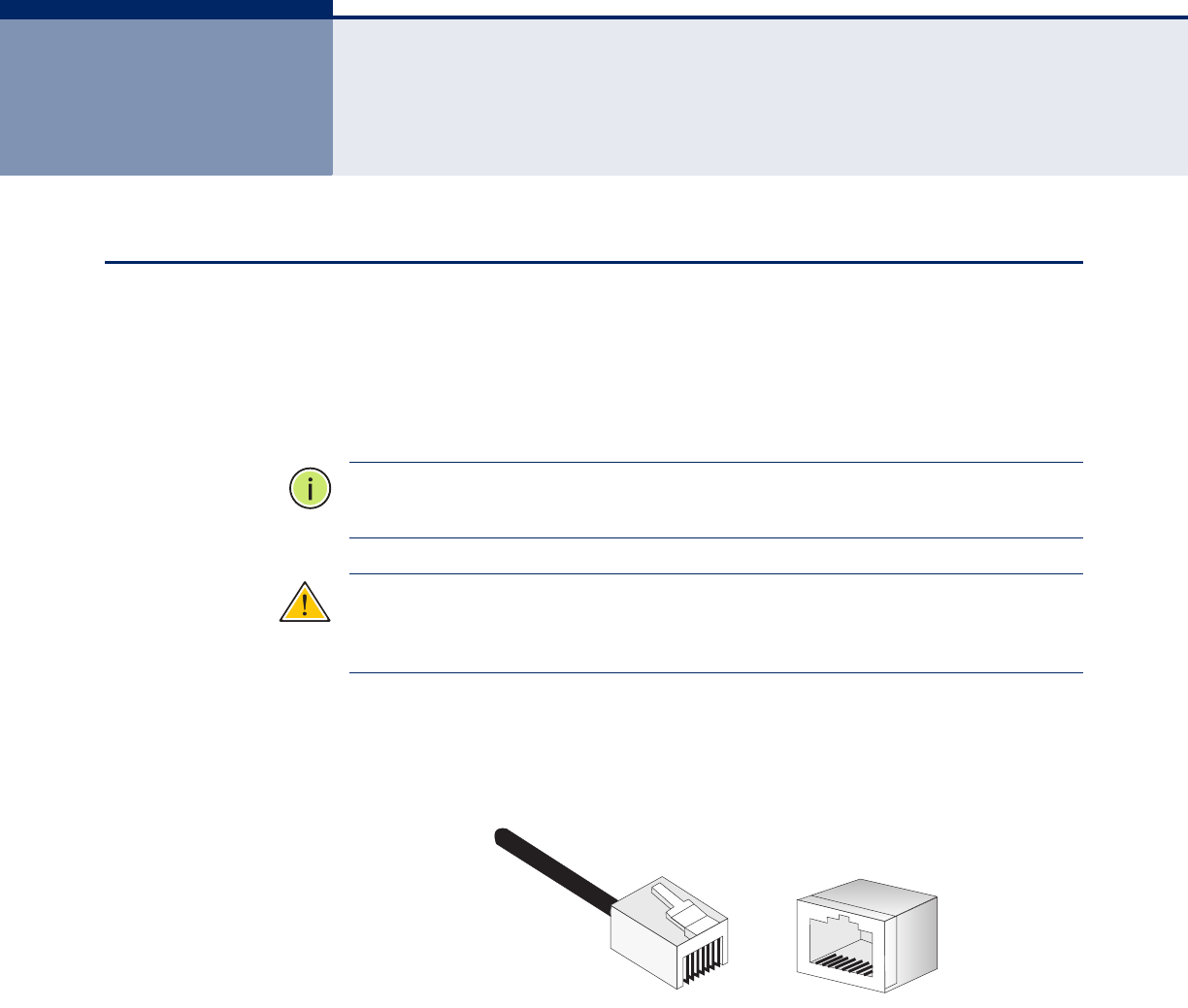
– 247 –
CCABLES AND PINOUTS
TWISTED-PAIR CABLE ASSIGNMENTS
For 10/100BASE-TX connections, a twisted-pair cable must have two pairs
of wires. For 1000BASE-T connections the twisted-pair cable must have
four pairs of wires. Each wire pair is identified by two different colors. For
example, one wire might be green and the other, green with white stripes.
Also, an RJ-45 connector must be attached to both ends of the cable.
N
OTE
:
Each wire pair must be attached to the RJ-45 connectors in a specific
orientation.
C
AUTION
:
DO NOT plug a phone jack connector into the RJ-45 port. Use
only twisted-pair cables with RJ-45 connectors that conform with FCC
standards.
The following figure illustrates how the pins on the RJ-45 connector are
numbered. Be sure to hold the connectors in the same orientation when
attaching the wires to the pins.
Figure 60: RJ-45 Connector
81
1
8

A
PPENDIX
C
| Cables and Pinouts
10/100BASE-TX Pin Assignments
– 248 –
10/100BASE-TX PIN ASSIGNMENTS
Use unshielded twisted-pair (UTP) or shielded twisted-pair (STP) cable for
RJ-45 connections: 100-ohm Category 3 or better cable for 10 Mbps
connections. Also be sure that the length of any twisted-pair connection
does not exceed 100 meters (328 feet).
The RJ-45 port on the access point supports automatic MDI/MDI-X
operation, so you can use straight-through or crossover cables for all
network connections to PCs, switches, or hubs. In straight-through cable,
pins 1, 2, 3, and 6, at one end of the cable, are connected straight through
to pins 1, 2, 3, and 6 at the other end of the cable.
STRAIGHT-THROUGH WIRING
If the twisted-pair cable is to join two ports and only one of the ports has
an internal crossover (MDI-X), the two pairs of wires must be straight-
through. (When auto-negotiation is enabled for any RJ-45 port on this
switch, you can use either straight-through or crossover cable to connect
to any device type.)
You must connect all four wire pairs as shown in the following diagram to
support Gigabit Ethernet connections.
Table 32: 10/100BASE-TX MDI and MDI-X Port Pinouts
PIN MDI Signal Namea
a. The “+” and “-” signs represent the polarity of the wires that make up each wire pair.
MDI-X Signal Name
1 Transmit Data plus (TD+) Receive Data plus (RD+)
2 Transmit Data minus (TD-) Receive Data minus (RD-)
3 Receive Data plus (RD+) Transmit Data plus (TD+)
6 Receive Data minus (RD-) Transmit Data minus (TD-)
4, 5, 7, 8 Not used Not used
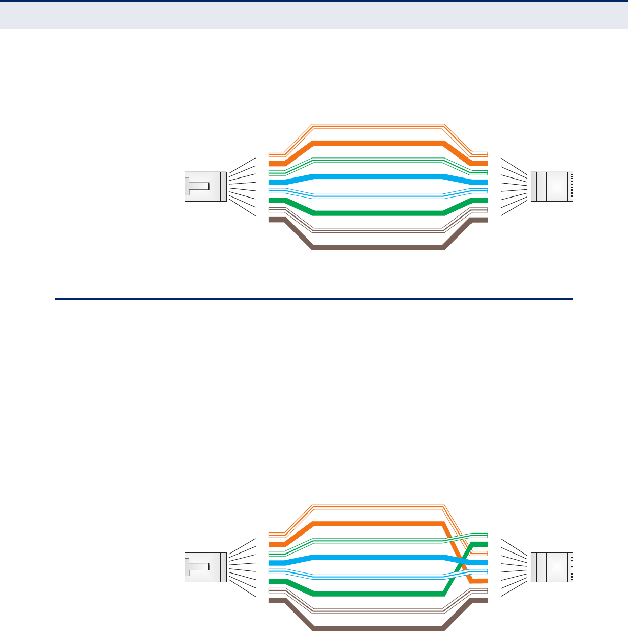
A
PPENDIX
C
| Cables and Pinouts
Crossover Wiring
– 249 –
Figure 61: Straight Through Wiring
CROSSOVER WIRING
If the twisted-pair cable is to join two ports and either both ports are
labeled with an “X” (MDI-X) or neither port is labeled with an “X” (MDI), a
crossover must be implemented in the wiring. (When auto-negotiation is
enabled for any RJ-45 port on this switch, you can use either straight-
through or crossover cable to connect to any device type.)
You must connect all four wire pairs as shown in the following diagram to
support Gigabit Ethernet connections.
Figure 62: Crossover Wiring
White/Orange Stripe
Orange
White/Green Stripe
Green
1
2
3
4
5
6
7
8
1
2
3
4
5
6
7
8
EIA
/
TIA 568B RJ-45 Wiring
S
tandard
10/100BASE-TX Straight-through Cable
End A End B
Blue
White/Blue Stripe
Brown
White/Brown Stripe
White/Orange Stripe
Orange
White/Green Stripe
1
2
3
4
5
6
7
8
1
2
3
4
5
6
7
8
EIA
/
TIA 568B RJ-45 Wiring
S
tandard
10/100BASE-TX Crossover Cable
End A End B
Green
Blue
White/Blue Stripe
Brown
White/Brown Stripe

A
PPENDIX
C
| Cables and Pinouts
1000BASE-T Pin Assignments
– 250 –
1000BASE-T PIN ASSIGNMENTS
All 1000BASE-T ports support automatic MDI/MDI-X operation, so you can
use straight-through cables for all network connections to PCs or servers,
switches or hubs.
The table below shows the 1000BASE-T MDI and MDI-X port pinouts. These
ports require that all four pairs of wires be connected. Note that for
1000BASE-T operation, all four pairs of wires are used for both transmit
and receive.
Use 100-ohm Category 5, 5e or 6 unshielded twisted-pair (UTP) or shielded
twisted-pair (STP) cable for 1000BASE-T connections. Also be sure that the
length of any twisted-pair connection does not exceed 100 meters (328
feet).
CABLE TESTING FOR
EXISTING CATEGORY 5
CABLE
Installed Category 5 cabling must pass tests for Attenuation, Near-End
Crosstalk (NEXT), and Far-End Crosstalk (FEXT). This cable testing
information is specified in the ANSI/TIA/EIA-TSB-67 standard. Additionally,
cables must also pass test parameters for Return Loss and Equal-Level Far-
End Crosstalk (ELFEXT). These tests are specified in the ANSI/TIA/EIA-
TSB-95 Bulletin, “The Additional Transmission Performance Guidelines for
100 Ohm 4-Pair Category 5 Cabling.”
Note that when testing your cable installation, be sure to include all patch
cables between switches and end devices.
ADJUSTING EXISTING
CATEGORY 5 CABLING
TO RUN 1000BASE-T
If your existing Category 5 installation does not meet one of the test
parameters for 1000BASE-T, there are basically three measures that can be
applied to try and correct the problem:
1. Replace any Category 5 patch cables with high-performance Category
5e or Category 6 cables.
Table 33: 1000BASE-T MDI and MDI-X Port Pinouts
Pin MDI Signal Name MDI-X Signal Name
1 Bi-directional Pair A Plus (BI_DA+) Bi-directional Pair B Plus (BI_DB+)
2 Bi-directional Pair A Minus (BI_DA-) Bi-directional Pair B Minus (BI_DB-)
3 Bi-directional Pair B Plus (BI_DB+) Bi-directional Pair A Plus (BI_DA+)
4 Bi-directional Pair C Plus (BI_DC+) Bi-directional Pair D Plus (BI_DD+)
5 Bi-directional Pair C Minus (BI_DC-) Bi-directional Pair D Minus (BI_DD-)
6 Bi-directional Pair B Minus (BI_DB-) Bi-directional Pair A Minus (BI_DA-)
7 Bi-directional Pair D Plus (BI_DD+) Bi-directional Pair C Plus (BI_DC+)
8 Bi-directional Pair D Minus (BI_DD-) Bi-directional Pair C Minus (BI_DC-)

A
PPENDIX
C
| Cables and Pinouts
Console Port Pin Assignments
– 251 –
2. Reduce the number of connectors used in the link.
3. Reconnect some of the connectors in the link.
CONSOLE PORT PIN ASSIGNMENTS
The RJ-45 console port on the front panel of the access point is used to
connect to the access point for out-of-band console configuration to a DB-9
connector on a PC. The command-line configuration program can be
accessed from a terminal, or a PC running a terminal emulation program.
The pin assignments and cable wiring used to connect to the console port
are provided in the following table.
Figure 63: DB-9 Connector
WIRING MAP FOR SERIAL CABLE
Table 34: 10/100BASE-TX MDI and MDI-X Port Pinouts
PINa
a. The left hand column pin assignments are for the male DB-9 connector on the access
point. Pin 3 (TXD or “transmit data”) must emerge on the management console’s end
of the connection as RXD (“receive data”).
MDI Signal Name MDI-X Signal Name
2 RXD <---------RXD ------------ 3 TxD
3 TXD -----------TXD ----------> 2 RxD
5 SGND -----------SGND ---------- 5 SGND
15
69

– 252 –
GLOSSARY
10BASE-T IEEE 802.3-2005 specification for 10 Mbps Ethernet over two pairs of
Category 3 or better UTP cable.
100BASE-TX IEEE 802.3-2005 specification for 100 Mbps Fast Ethernet over two pairs of
Category 5 or better UTP cable.
1000BASE-T IEEE 802.3ab specification for 1000 Mbps Gigabit Ethernet over four pairs
of Category 5 or better UTP cable.
ACCESS POINT An internetworking device that seamlessly connects wired and wireless
networks. Access points attached to a wired network, support the creation
of multiple radio cells that enable roaming throughout a facility.
ADVANCED ENCRYPTION
STANDARD (AES)
An encryption algorithm that implements symmetric key cryptography. AES
provides very strong encryption using a completely different ciphering
algorithm to TKIP and WEP.
AUTHENTICATION The process to verify the identity of a client requesting network access.
IEEE 802.11 specifies two forms of authentication: open system and
shared key.
BACKBONE The core infrastructure of a network. The portion of the network that
transports information from one central location to another central location
where it is unloaded onto a local system.
BEACON A signal periodically transmitted from the access point that is used to
identify the service set, and to maintain contact with wireless clients.
BROADCAST KEY Broadcast keys are sent to stations using dynamic keying. Dynamic
broadcast key rotation is often used to allow the access point to generate a
random group key and periodically update all key-management capable
wireless clients.

G
LOSSARY
– 253 –
DYNAMIC HOST
CONFIGURATION
PROTOCOL (DHCP)
Provides a framework for passing configuration information to hosts on a
TCP/IP network. DHCP is based on the Bootstrap Protocol (BOOTP), adding
the capability of automatic allocation of reusable network addresses and
additional configuration options.
ENCRYPTION Data passing between the access point and clients can use encryption to
protect from interception and evesdropping.
ETHERNET A popular local area data communications network, which accepts
transmission from computers and terminals.
FILE TRANSFER
PROTOCOL (FTP)
A TCP/IP protocol used for file transfer.
HYPERTEXT TRANSFER
PROTOCOL (HTTP)
HTTP is a standard used to transmit and receive all data over the World
Wide Web.
IEEE 802.11AA wireless standard that supports high-speed communications in the 5 GHz
band using Orthogonal Frequency Division Multiplexing (OFDM). The
standard supports data rates of 6, 12, 24, and 54 Mbps.
IEEE 802.11BA wireless standard that supports wireless communications in the 2.4 GHz
band using Direct Sequence Spread Spectrum (DSSS). The standard
provides for data rates of 1, 2, 5.5, and 11 Mbps.
IEEE 802.11GA wireless standard that supports wireless communications in the 2.4 GHz
band using Orthogonal Frequency Division Multiplexing (OFDM). The
standard provides for data rates of 6, 9, 12, 18, 24, 36, 48, 54 Mbps. IEEE
802.11g is also backward compatible with IEEE 802.11b.
IEEE 802.11NA wireless standard that supports wireless communications in the 2.4 GHz
band using Orthogonal Frequency Division Multiplexing (OFDM). The
standard provides for data rates of 27, 54, 81, 108, 162, 216, 243, 270,
300 Mbps. IEEE 802.11n is also backward compatible with IEEE 802.11b/g.
INFRASTRUCTURE An integrated wireless and wired LAN is called an infrastructure
configuration.
LOCAL AREA NETWORK
(LAN)
A group of interconnected computer and support devices.

G
LOSSARY
– 254 –
MAC ADDRESS The physical layer address used to uniquely identify network nodes.
NETWORK TIME
PROTOCOL (NTP)
NTP provides the mechanisms to synchronize time across the network. The
time servers operate in a hierarchical-master-slave configuration in order
to synchronize local clocks within the subnet and to national time
standards via wire or radio.
OPEN SYSTEM A security option which broadcasts a beacon signal including the access
point’s configured SSID. Wireless clients can read the SSID from the
beacon, and automatically reset their SSID to allow immediate connection
to the nearest access point.
ORTHOGONAL
FREQUENCY DIVISION
MULTIPLEXING (ODFM)
OFDM allows multiple users to transmit in an allocated band by dividing the
bandwidth into many narrow bandwidth carriers.
REPEATER AND BRIDGE Repeater and bridge can provide an extended link to a remote access point
from the wired LAN. Access Point working in this mode could connect to
another AP in Access Point mode or Repeater and Bridge mode. Whenever
there are two APs having wireless link together (one in Access Point or
Repeater and Bridge mode, another using Repeater and Bridge mode), and
also have wired link separately, these two APs are also working as
.bridging. for the two wired links.
SERVICE SET IDENTIFIER
(SSID)
An identifier that is attached to packets sent over the wireless LAN and
functions as a password for joining a particular radio cell; i.e., Basic Service
Set (BSS).
SESSION KEY Session keys are unique to each client, and are used to authenticate a
client connection, and correlate traffic passing between a specific client and
the access point.
SHARED KEY A shared key can be used to authenticate each client attached to a wireless
network. Shared Key authentication must be used along with the 802.11
Wireless Equivalent Privacy algorithm.
SIMPLE NETWORK TIME
PROTOCOL (SNTP)
SNTP allows a device to set its internal clock based on periodic updates
from a Network Time Protocol (NTP) server. Updates can be requested from
a specific NTP server, or can be received via broadcasts sent by NTP
servers.

G
LOSSARY
– 255 –
TEMPORAL KEY
INTEGRITY PROTOCOL
(TKIP)
A data encryption method designed as a replacement for WEP. TKIP avoids
the problems of WEP static keys by dynamically changing data encryption
keys.
TRIVIAL FILE TRANSFER
PROTOCOL (TFTP)
A TCP/IP protocol commonly used for software downloads.
VIRTUAL ACCESS POINT
(VAP)
Virtual AP technology multiplies the number of Access Points present within
the RF footprint of a single physical access device. With Virtual AP
technology, WLAN users within the device.s footprint can associate with
what appears to be different access points and their associated network
services. All the services are delivered using a single radio channel,
enabling Virtual AP technology to optimize the use of limited WLAN radio
spectrum.
WI-FI PROTECTED
ACCESS
WPA employs 802.1X as its basic framework for user authentication and
dynamic key management to provide an enhanced security solution for
802.11 wireless networks.
WIRED EQUIVALENT
PRIVACY (WEP)
WEP is based on the use of security keys and the popular RC4 encryption
algorithm. Wireless devices without a valid WEP key will be excluded from
network traffic.
WPA PRE-SHARED KEY
(WPA-PSK)
WPA-PSK can be used for small office networks with a limited number of
users that may not need a high level of security. WPA-PSK provides a
simple security implementation that uses just a pre-shared password for
network access.

– 256 –
INDEX
NUMERICS
802.11g 202
A
antennas 30
authentication
cipher suite 220
closed system 213
MAC address 177, 178
type 213
B
beacon
interval 210
rate 210
BOOTP 196, 197
bridge 37
C
channel 204
closed system 213
community name, configuring 154
community string 154
configuration settings, saving or restoring 168
connect console port 42
connect Ethernet cable 42
connecting and powering on 42
console port 33
country code
configuring 128
CTS 211
D
device status, displaying 137
DHCP 196, 197
DNS 196
Domain Name Server See DNS
downloading software 168
DTIM 210
E
Ethernet port 33
event logs 146
external antennas 30
F
filter 177
address 177
between wireless clients 181
local bridge 181
local or remote 179
management access 182
protocol types 184
VLANs 232
firmware
displaying version 138
upgrading 168
G
gateway address 196
H
hardware capabilities 27
hardware description 29
hardware version, displaying 138
HTTP, secure server 134
HTTPS 134
I
IEEE 802.11a 202
configuring interface 202
radio channel 204
IEEE 802.11g
configuring interface 202
radio channel 204
IEEE 802.1x 175
configuring 175
infrastructure wireless LAN 35
initial configuration 43
installing the access point 39
interference issues 35
introduction 27
IP address 48, 55
BOOTP/DHCP 196, 197
configuring 196, 197
K
key features 27

I
NDEX
– 257 –
L
LED indicators 32
location selection 39
log messages 144
server 144
M
MAC address, authentication 177, 178
mounting on a horizontal surface 40
mounting on a wall 41
N
network configuration 35
O
open system 213
P
package contents 28
password
configuring 131
management 131
port priority
STA 199
position antennas 42
power connector 33
R
radio channel
802.11a interface 204
802.11g interface 204
RADIUS 170
reset button 34
roaming 36
RTSthreshold 211
S
Secure Socket Layer See SSL
self test 42
shared key 221
SNMP 154
community name 154
community string 154
enabling traps 156
trap destination 157
trap manager 157
SNTP 148
enabling client 149
server 148
software
displaying version 138
downloading 168
SSID 212
SSL 134
STAinterface settings 198–??
path cost 198
port priority 199
startup files, setting 167
station status 217
status
displaying device status 137
displaying station status 217
subnet mask 48, 55
system clock, setting 149
system log
enabling 143
server 144
system software, downloading from server 168
T
time zone 150
transmit power, configuring 205
trap destination 157
trap manager 157
U
upgrading software 168
user name, manager 130
user password 130, 131
V
VLAN
configuration 232
W
WEP
shared key 221
WPA
pre-shared key 224

SMCE21011
TECHNICAL SUPPORT
From U.S.A. and Canada (24 hours a day, 7 days a week)
Phn: 800-SMC-4-YOU / 949-679-8000
Fax: 949-502-3400
ENGLISH
Technical Support information available at www.smc.com
FRENCH
Informations Support Technique sur www.smc.com
DEUTSCH
Technischer Support und weitere Information unter www.smc.com
SPANISH
En www.smc.com Ud. podrá encontrar la información relativa a servicios de soporte técnico
DUTCH
Technische ondersteuningsinformatie beschikbaar op www.smc.com
PORTUGUES
Informações sobre Suporte Técnico em www.smc.com
SWEDISH
Information om Teknisk Support finns tillgängligt på www.smc.com
INTERNET
E-mail address: techsupport@smc.com
Driver updates
http://www.smc.com/index.cfm?action=tech_support_drivers_downloads
World Wide Web
http://www.smc.com/
XXXXXXXXXXXXXX R01 20 Mason • Irvine, CA 92618 • Phn: 949-679-8000 • www.smc.com