Accton Technology HIVEAP20AG HiveAP 20ag User Manual UserMan HEDHIVEAP20AG revised3
Accton Technology Corp HiveAP 20ag UserMan HEDHIVEAP20AG revised3
Contents
- 1. User Manual 1
- 2. User Manual 2
User Manual 1
Aerohive Deployment Guide

1
Aerohive Deployment Guide
For HiveAP and HiveManager Devices
Aerohive Technical Publications
Copyright Notice
Copyright © 2008 Aerohive Networks, Inc. All rights reserved.
Aerohive Networks, the Aerohive Networks logo, HiveOS, HiveAP, and HiveManager are trademarks of Aerohive
Networks, Inc. All other trademarks and registered trademarks are the property of their respective companies.
Information in this document is subject to change without notice. No part of this document may be reproduced or
transmitted in any form or by any means, electronic or mechanical, for any purpose, without receiving written
permission from:
Aerohive Networks, Inc.
3150-C Coronado Drive
Santa Clara, CA 95054
P/N 330002-06, Rev. A

HiveAP Compliance Information
2Aerohive
HiveAP Compliance Information
Federal Communication Commission Interference
Statement
This equipment has been tested and found to comply with the limits for
a Class B digital device, pursuant to Part 15 of the FCC Rules. These
limits are designed to provide reasonable protection against harmful
interference in a residential installation. This equipment generates,
uses and can radiate radio frequency energy and, if not installed and
used in accordance with the instructions, may cause harmful
interference to radio communications. However, there is no guarantee
that interference will not occur in a particular installation. If this
equipment does cause harmful interference to radio or television
reception, which can be determined by turning the equipment off and
on, the user is encouraged to try to correct the interference by one of
the following measures:
•Reorient or relocate the receiving antenna
•Increase the separation between the equipment and receiver
•Connect the equipment into an outlet on a circuit different from
that to which the receiver is connected
•Consult the dealer or an experienced radio/TV technician for help
FCC Caution: Any changes or modifications not expressly approved by
the party responsible for compliance could void the user's authority to
operate this equipment. This device complies with Part 15 of the FCC
Rules. Operation is subject to the following two conditions: (1) This
device may not cause harmful interference, and (2) this device must
accept any interference received, including interference that may
cause undesired operation.
Important: FCC Radiation Exposure Statement
This equipment complies with FCC radiation exposure limits set forth
for an uncontrolled environment. This equipment should be installed
and operated with a minimum distance of 20 centimeters (8 inches)
between the radiator and your body. This transmitter must not be co-
located or operating in conjunction with any other antenna or
transmitter.
Wireless 5 GHz Band Statements
To comply with FCC regulations, do not use channels 36, 40, 44, and 48
in the 5.15–5.25 GHz band when HiveAPs are deployed outdoors. In
addition, the transmission power is limited to a maximum of 15 dBm.
Because radar systems use some bands in the 5 GHz spectrum, WLAN
devices operating in these bands must use DFS (Dynamic Frequency
Selection) to detect radar activity and switch channels automatically to
avoid interfering with radar operations. DFS is required for WLAN
devices operating within the 5.25–5.35 GHz UNII-2 and the 5.47–5.725
UNII Mid-Band spectrums in the FCC regions of North America and the
ETSI regions in the European Community. DFS is not required for WLAN
devices operating in the 5.725-5.850 GHz spectrum in FCC regions. (The
5.725-5.850 GHz spectrum is not available for wireless use in ETSI
regions.) HiveAP 300 series models support DFS-FCC and DFS-ETSI and
are permitted to operate in the 5.25–5.35 GHz and 5.47–5.725 GHz
bands in outdoor deployments in the FCC and ETSI regions.
Note: The term "IC" before the radio certification number signifies that
Industry Canada technical specifications were met.
Industry Canada - Class B
This digital apparatus does not exceed the Class B limits for radio noise
emissions from digital apparatus as set out in the interference-causing
equipment standard entitled "Digital Apparatus," ICES-003 of Industry
Canada.
Cet appareil numérique respecte les limites de bruits radioélectriques
applicables aux appareils numériques de Classe B prescrites dans la
norme sur le matériel brouilleur: "Appareils Numériques," NMB-003
édictée par l'Industrie.
Wi-Fi Certification
The Wi-Fi CERTIFIED™ Logo is a certification mark of the Wi-Fi
Alliance®. The Aerohive HiveAP 20 ag has been certified for WPA™,
WPA2™, WMM® (Wi-Fi Multimedia™), WMM Power Save, and the
following types of EAP (Extensible Authentication Protocol):
•EAP-TLS
•EAP-TTLS/MSCHAPv2
•PEAPv0/EAP-MSCHAPv2
•PEAPv1/EAP-GTC
•EAP-SIM
EC Conformance Declaration
Marking by the above symbol indicates compliance with the Essential
Requirements of the R&TTE Directive of the European Union (1999/5/
EC). This equipment meets the following conformance standards:
•EN 60950-1 (IEC 60950-1) - Product Safety
•EN 301 893 - Technical requirements for 5 GHz radio equipment
•EN 300 328 - Technical requirements for 2.4 GHz radio equipment
•EN 301 489-1 / EN 301 489-17 - EMC requirements for radio
equipment
Countries of Operation and Conditions
of Use in the European Community
HiveAPs are intended to be operated in all countries of the European
Community. Requirements for indoor vs. outdoor operation, license
requirements and allowed channels of operation apply in some
countries as described below.
•Before operating a HiveAP, the admin or installer must properly
enter the current country of operation in the command line
interface as described in "Appendix A Country Codes" on page177.
Note to U.S. model owners: To comply with U.S. FCC regulations,
the country selection function has been completely removed from
all U.S. models. The above function is for non-U.S. models only.
•HiveAPs automatically limit the allowable channels determined by
the current country of operation. Incorrectly entering the country
of operation might result in illegal operation and cause harmful
interference to other systems. The admin is obligated to ensure
HiveAPs are operating according to the channel limitations,
indoor/outdoor restrictions and license requirements for each
European Community country as described in this section.
•HiveAPs can be operated indoors or outdoors in all countries of the
European Community using the 2.4 GHz band: Channels 1 - 13,
except where noted below.
–In Italy, you must apply for a license from the national
spectrum authority to operate a HiveAP outdoors.
–In Belgium outdoor operation is only permitted using the 2.46 -
2.4835 GHz band: Channel 13.
–In France outdoor operation is only permitted using the 2.4 -
2.454 GHz band: Channels 1 - 7.
•HiveAPs using the 5.15–5.25 GHz band (Channels 36, 40, 44, 48)
are restricted to indoor use when operated in the European
Community. Because the frequency ranges 5.25–5.35 and 5.47–
5.725 are affected by DFS (Dynamic Frequency Selection), HiveAP
20 and 28 models block channels 52, 56, 60, 64, and 100, 104, 108,
112, 116, 120, 124, 128, 132, 136, 140.
Deployment Guide 3
HIVEAP COMPLIANCE INFORMATION
The availability of some specific channels and/or operational
frequency bands are country dependent and are firmware
programmed at the factory to match the intended destination.
The firmware setting is not accessible by the end user.
•The 5 GHz Turbo Mode feature is not allowed for operation in any
European Community country. You can find the current setting for
this feature in two places. In the HiveManager GUI, click
Configuration > Network Objects>Radio Profiles > profile >
Advanced. In the HiveAP CLI, enter this command: show radio
profile profile. By default, Turbo Mode is disabled.
Declaration of Conformity in Languages
of the European Community
HiveAP 20 ag Safety Compliance
Power Cord Safety
Please read the following safety information carefully before installing
a HiveAP.
Warning: Installation and removal of HiveAPs must be carried out by
qualified personnel only.
•HiveAPs must be connected to an earthed (grounded) outlet to
comply with international safety standards.
•Do not connect HiveAPs to an A.C. outlet (power supply) without
an earth (ground) connection.
•The appliance coupler (the connector to the unit and not the wall
plug) must have a configuration for mating with an EN 60320/IEC
320 appliance inlet.
•The socket outlet must be near the HiveAP and easily accessible.
You can only remove power from a HiveAP by disconnecting the
power cord from the outlet.
•HiveAPs operate under SELV (Safety Extra Low Voltage) conditions
according to IEC 60950. The conditions are only maintained if the
equipment to which they are connected also operates under SELV
conditions.
•A HiveAP receiving power through its PoE (Power over Ethernet)
interface must be in the same building as the equipment from
which it receives power.
France and Peru only:
HiveAPs cannot be powered from IT* supplies. If your supplies are of IT
type, then a HiveAP must be powered by 230 V (2P+T) via an isolation
transformer ratio 1:1, with the secondary connection point labelled
Neutral, connected directly to earth (ground).
* Impédance à la terre
Important! Before making connections, make sure you have the correct
cord set. Check it (read the label on the cable) against the description
on the following page.
Veuillez lire attentivement les informations de sécurité relatives à
l'installation d'un point d'accès HiveAP.
EnglishHereby, Edgecore, declares that this Radio LAN
device is in compliance with the essential
requirements and other relevant provisions of
Directive 1999/5/EC.
FinnishValmistaja Edgecore vakuuttaa täten että Radio LAN
device tyyppinen laite on direktiivin 1999/5/EY
oleellisten vaatimusten ja sitä koskevien direktiivin
muiden ehtojen mukainen.
Dutch Hierbij verklaart Edgecore dat het toestel Radio
LAN device in overeenstemming is met de
essentiële eisen en de andere relevante bepalingen
van richtlijn 1999/5/EG.
Bij deze Edgecore dat deze Radio LAN device
voldoet aan de essentiële eisen en aan de overige
relevante bepalingen van Richtlijn 1999/5/EC.
FrenchPar la présente Edgecore déclare que cet appareil
Radio LAN est conforme aux exigences essentielles
et aux autres dispositions relatives à la directive
1999/5/CE.
SwedishHärmed intygar Edgecore att denna Radio LAN
device står I överensstämmelse med de väsentliga
egenskapskrav och övriga relevanta bestämmelser
som framgår av direktiv 1999/5/EG.
Danish Undertegnede Edgecore erklærer herved, at
følgende udstyr Radio LAN device overholder de
væsentlige krav og øvrige relevante krav i direktiv
1999/5/EF.
GermanHiermit erklärt Edgecore, dass sich dieser/diese/
dieses Radio LAN device in Übereinstimmung mit
den grundlegenden Anforderungen und den anderen
relevanten Vorschriften der Richtlinie 1999/5/EG
befindet". (BMWi)
Hiermit erklärt Edgecore die Übereinstimmung des
Gerätes Radio LAN device mit den grundlegenden
Anforderungen und den anderen relevanten
Festlegungen der Richtlinie 1999/5/EG. (Wien)
Greek
Italian Con la presente Edgecore dichiara che questo Radio
LAN device è conforme ai requisiti essenziali ed alle
altre disposizioni pertinenti stabilite dalla direttiva
1999/5/CE.
SpanishPor medio de la presente Manufacturer declara que
el Radio LAN device cumple con los requisitos
esenciales y cualesquiera otras disposiciones
aplicables o exigibles de la Directiva 1999/5/CE.
PortugueseManufacturer declara que este Radio LAN device
está conforme com os requisitos essenciais e outras
disposições da Directiva 1999/5/CE.
Power Cord Set
U.S.A.
and Canada The cord set must be UL-approved and CSA certified.
Minimum specifications for the flexible cord:
- No. 18 AWG not longer than 2 meters, or 16 AWG
- Type SV or SJ
- 3-conductor
The cord set must have a rated current capacity of at
least 10 A.
The attachment plug must be an earth-grounding
type with NEMA 5-15P (15 A, 125 V) or NEMA 6-15 (15
A, 250 V) configuration.
DenmarkThe supply plug must comply with Section 107-2-D1,
Standard DK2-1a or DK2-5a.
SwitzerlandThe supply plug must comply with SEV/ASE 1011.
U.K. The supply plug must comply with BS1363 (3-pin 13 A)
and be fitted with a 5 A fuse that complies with
BS1362.
The mains cord must be <HAR> or <BASEC> marked and
be of type HO3VVF3GO.75 (minimum).
EuropeThe supply plug must comply with CEE7/7
("SCHUKO").
The mains cord must be <HAR> or <BASEC> marked and
be of type HO3VVF3GO.75 (minimum).
IEC-320 receptacle.
HiveAP Compliance Information
4Aerohive
Avertissement: L'installation et la dépose de points d'accès HiveAP
doivent être effectuées uniquement par un personnel qualifié.
•Les points d'accès HiveAP doivent être connectés sur le secteur
par une prise électrique munie de terre (masse) afin de respecter
les standards internationaux de sécurité.
•Ne jamais connecter des points d'accès HiveAP à une alimentation
électrique non-pourvue de terre (masse).
•Le boitier d'alimentation (connecté directement au point d'accès)
doit être compatible avec une entrée électrique de type EN
60320/IEC 320.
•La prise secteur doit se trouver à proximité du point d'accès
HiveAP et facilement accessible. Vous ne pouvez mettre hors
tension un point d'accès HiveAP qu'en débranchant son
alimentation électrique au niveau de cette prise.
•Pour des raisons de sécurité, le point d'accès HiveAP fonctionne à
une tension extrêmement basse, conformément à la norme IEC
60950. Les conditions de sécurité sont valables uniquement si
l'équipement auquel le point d'accès HiveAP est raccordé
fonctionne également selon cette norme.
•Un point d'accès HiveAP alimenté par son interface réseau
Ethernet en mode POE (Power over Ethernet) doit être
physiquement dans le même bâtiment que l'équipement réseau
qui lui fournit l'électricité.
France et Pérou uniquement:
Un point d'accès HiveAP ne peut pas être alimenté par un dispositif à
impédance à la terre. Si vos alimentations sont du type impédance à la
terre, alors le point d'accès HiveAP doit être alimenté par une tension
de 230 V (2P+T) via un transformateur d'isolement à rapport 1:1, avec
le neutre connecté directement à la terre (masse).
Bitte unbedingt vor dem Einbauen des HiveAP die folgenden
Sicherheitsanweisungen durchlesen.
Warnung: Die Installation und der Ausbau des Geräts darf nur durch
Fachpersonal erfolgen.
•Das Gerät sollte nicht an eine ungeerdete Wechselstromsteckdose
angeschlossen werden.
•Das Gerät muß an eine geerdete Steckdose angeschlossen werden,
welche die internationalen Sicherheitsnormen erfüllt.
•Der Gerätestecker (der Anschluß an das Gerät, nicht der
Wandsteckdosenstecker) muß einen gemäß EN 60320/IEC 320
konfigurierten Geräteeingang haben.
•Die Netzsteckdose muß in der Nähe des Geräts und leicht
zugänglich sein. Die Stromversorgung des Geräts kann nur durch
Herausziehen des Gerätenetzkabels aus der Netzsteckdose
unterbrochen werden.
•Der Betrieb dieses Geräts erfolgt unter den SELV-Bedingungen
(Sicherheitskleinstspannung) gemäß IEC 60950. Diese Bedingungen
sind nur gegeben, wenn auch die an das Gerät angeschlossenen
Geräte unter SELV-Bedingungen betrieben werden.
Liability Disclaimer
Installation of Aerohive equipment must comply with local and national electrical codes and with other regulations governing this type of installation.
Aerohive Networks, its channel partners, resellers, and distributors assume no liability for personal injury, property damage, or violation of
government regulations that may arise from failing to comply with the instructions in this guide and appropriate electrical codes.
Cordon électrique - Il doit être agréé dans le pays d'utilisation
Etats-Unis
et Canada Le cordon doit avoir reçu l'homologation des UL et un
certificat de la CSA.
Les spécifications minimales pour un cable flexible
- AWG No. 18, ou AWG No. 16 pour un cable de
longueur inférieure à 2 mètres.
- Type SV ou SJ
- 3 conducteurs
Le cordon doit être en mesure d'acheminer un
courant nominal d'au moins 10 A.
La prise femelle de branchement doit être du type à
mise à la terre (mise à la masse) et respecter la
configuration NEMA 5-15P (15 A, 125 V) ou NEMA 6-
15P (15 A, 250 V).
DanemarkLa prise mâle d'alimentation doit respecter la section
107-2 D1 de la norme DK2 1a ou DK2 5a.
SuisseLa prise mâle d'alimentation doit respecter la norme
SEV/ASE 1011.
EuropeLa prise secteur doit être conforme aux normes CEE
7/7 ("SCHUKO").
LE cordon secteur doit porter la mention <HAR> ou
<BASEC> et doit être de type HO3VVF3GO.75
(minimum).
Stromkabel. Dies muss von dem Land, in dem es benutzt wird
geprüft werden:
U.S.A.
und
Kanada
Der Cord muß das UL gepruft und war das CSA
beglaubigt.
Das Minimum spezifikation fur der Cord sind:
- Nu. 18 AWG - nicht mehr als 2 meter, oder 16 AWG.
- Der typ SV oder SJ
- 3-Leiter
Der Cord muß haben eine strombelastbarkeit aus
wenigstens 10 A.
Dieser Stromstecker muß hat einer erdschluss mit der
typ NEMA 5-15P (15A, 125V) oder NEMA 6-15P (15A,
250V) konfiguration.
DanemarkDieser Stromstecker muß die ebene 107-2-D1, der
standard DK2-1a oder DK2-5a Bestimmungen
einhalten.
SchweizDieser Stromstecker muß die SEV/ASE
1011Bestimmungen einhalten.
EuropeEurope Das Netzkabel muß vom Typ HO3VVF3GO.75
(Mindestanforderung) sein und die Aufschrift <HAR>
oder <BASEC> tragen.
Der Netzstecker muß die Norm CEE 7/7 erfüllen
("SCHUKO").
Deployment Guide 5
Contents
Chapter 1 Preparing for a WLAN Deployment...............................................9
Assessing Your Requirements.............................................................................10
Planning......................................................................................................10
Upgrading from Existing Wi-Fi...................................................................................10
New WLAN Deployment...........................................................................................11
Site Surveys.........................................................................................................12
Budgeting Wi-Fi: The Chicken and Egg Problem..............................................................13
Planning Tools.................................................................................................13
Associated Access Point Costs...............................................................................14
Bandwidth Assumptions for Wi-Fi...............................................................................14
Overcoming Physical Impediments..............................................................................15
Preparing the Wired Network for Wireless....................................................................17
Operational Considerations................................................................................18
Tuning...............................................................................................................18
Troubleshooting....................................................................................................18
Management........................................................................................................18
Deploying with Confidence.......................................................................................18
Basic Wi-Fi Concepts.......................................................................................19
Chapter 2 The HiveAP 20 ag Platform.......................................................23
HiveAP 20 Product Overview..............................................................................24
Ethernet and Console Ports......................................................................................26
Status LEDs.........................................................................................................27
Antennas............................................................................................................28
Mounting the HiveAP 20....................................................................................29
Ceiling Mount.......................................................................................................29
Surface Mount......................................................................................................30
Device, Power, and Environmental Specifications.....................................................31
Chapter 3 The HiveAP 28 Outdoor Platform...............................................33
HiveAP 28 Product Overview..............................................................................34
Ethernet Port.......................................................................................................35
Power Connector..................................................................................................36
Antennas............................................................................................................37
Contents
6Aerohive
Mounting the HiveAP 28 and Attaching Antennas......................................................38
Pole Mount..........................................................................................................39
Strand Mount.......................................................................................................40
Surface Mount......................................................................................................41
Attaching Antennas................................................................................................42
Connecting Antennas Directly to the HiveAP 28..........................................................42
Mounting Antennas Separately..............................................................................42
Device, Power, and Environmental Specifications.....................................................44
Chapter 4 The HiveAP 340 Platform.........................................................45
HiveAP 340 Product Overview.............................................................................46
Ethernet and Console Ports......................................................................................48
Smart PoE......................................................................................................49
Aggregate and Redundant Interfaces......................................................................49
Console Port...................................................................................................51
Status LEDs.........................................................................................................52
Antennas............................................................................................................52
MIMO............................................................................................................53
Using MIMO with Legacy Clients.............................................................................55
Mounting the HiveAP 340..................................................................................56
Ceiling Mount.......................................................................................................56
Locking the HiveAP 340......................................................................................57
Surface Mount......................................................................................................58
Device, Power, and Environmental Specifications.....................................................59
Chapter 5 The HiveManager Platform.......................................................61
Product Overview...........................................................................................62
Ethernet and Console Ports......................................................................................63
Status LEDs.........................................................................................................64
Rack Mounting the HiveManager..........................................................................65
Device, Power, and Environmental Specifications.....................................................66
Chapter 6 The High Capacity HiveManager Platform.....................................67
Product Overview...........................................................................................68
Rack Mounting the High Capacity HiveManager........................................................70
Replacing Power Supplies..................................................................................73
Replacing Hard Disk Drives................................................................................74
Device, Power, and Environmental Specifications.....................................................75
Deployment Guide 7
Chapter 7 Using HiveManager.................................................................77
Installing and Connecting to the HiveManager GUI....................................................79
Introduction to the HiveManager GUI....................................................................82
Cloning Configurations............................................................................................83
Multiselecting......................................................................................................83
Sorting Displayed Data............................................................................................84
HiveManager Configuration Workflow...................................................................85
Updating Software on HiveManager......................................................................86
Updating HiveOS Firmware................................................................................87
Updating HiveAPs in a Mesh Environment......................................................................88
Chapter 8 HiveManager Configuration Examples..........................................89
Example 1: Mapping Locations and Installing HiveAPs................................................91
Setting Up Topology Maps........................................................................................91
Preparing the HiveAPs............................................................................................94
Using SNMP.....................................................................................................94
Using MAC Addresses..........................................................................................95
Example 2: Defining Network Objects and MAC Filters...............................................97
Defining a MAC OUI................................................................................................97
Mapping the MAC OUI and Services to Aerohive Classes................................................98
Defining VLANs...................................................................................................100
Creating IP Addresses...........................................................................................101
Creating a MAC Filter...........................................................................................103
Example 3: Providing Guest Access....................................................................104
Guest Access with Preshared Keys............................................................................104
Guest Access with Captive Web Portal.......................................................................105
Captive Web Portal with External DHCP and DNS Servers............................................105
Captive Web Portal with Internal DHCP and DNS Servers.............................................107
Customizing the Registration Page.......................................................................108
Loading Customized Captive Web Portal Files..........................................................111
Defining a Captive Web Portal............................................................................112
Example 4: Creating User Profiles......................................................................113
Example 5: Setting SSIDs.................................................................................117
Example 6: Setting Management Service Parameters...............................................120
Example 7: Defining AAA RADIUS Settings.............................................................123
Example 8: Creating Hives...............................................................................125
Contents
8Aerohive
Example 9: Creating WLAN Policies....................................................................126
WLANpolicy-hq1..................................................................................................126
WLANpolicy-hq1 (Page 1)..................................................................................126
WLANpolicy-hq1 (Page 2)..................................................................................128
WLANpolicy-hq1 (Page 3)..................................................................................131
WLANpolicy-hq2..................................................................................................134
WLANpolicy-branch1............................................................................................134
Example 10: Assigning Configurations to HiveAPs....................................................135
Chapter 9 HiveOS..............................................................................141
Common Default Settings and Commands.............................................................142
Configuration Overview..................................................................................143
Device-Level Configurations...................................................................................143
Policy-Level Configurations....................................................................................144
HiveOS Configuration File Types........................................................................145
Chapter 10 Deployment Examples (CLI)..................................................149
Example 1: Deploying a Single HiveAP.................................................................150
Example 2: Deploying a Hive............................................................................153
Example 3: Using IEEE 802.1X Authentication........................................................158
Example 4: Applying QoS................................................................................161
Example 5: Loading a Bootstrap Configuration.......................................................167
CLI Commands for Examples............................................................................170
Commands for Example 1......................................................................................170
Commands for Example 2......................................................................................170
Commands for Example 3......................................................................................171
Commands for Example 4......................................................................................172
Commands for Example 5......................................................................................174
Chapter 11 Traffic Types....................................................................175
Appendix A Country Codes..................................................................177

Deployment Guide 9
Chapter 1Preparing for a WLAN Deployment
To ensure a smooth WLAN deployment, you need to begin with a bit of planning. A straightforward review of your
deployment plan before you begin will result in optimal results more quickly. The goals of this chapter are to assist
you in assessing your readiness for WLAN implementation and to provide tips and tricks to resolve any issues that
might arise in your environment. The chapter covers the following topics:
•"Assessing Your Requirements" on page10
•"Planning" on page10
•"Upgrading from Existing Wi-Fi" on page10
•"New WLAN Deployment" on page11
•"Site Surveys" on page12
•"Budgeting Wi-Fi: The Chicken and Egg Problem" on page13
•"Bandwidth Assumptions for Wi-Fi" on page14
•"Overcoming Physical Impediments" on page15
•"Operational Considerations" on page18
•"Preparing the Wired Network for Wireless" on page17
•"Deploying with Confidence" on page18
Although this guide assumes an understanding of corporate data networking, previous experience with LAN
configuration and deployment, and some basic Wi-Fi understanding, the chapter concludes with a section that
provides additional support for the preceding sections: "Basic Wi-Fi Concepts" on page19.
Note: This guide assumes an understanding of corporate data networking and past experience with LAN
configuration and deployment. It also assumes some basic Wi-Fi understanding.

Chapter 1 Preparing for a WLAN Deployment
10 Aerohive
ASSESSING YOUR REQUIREMENTS
To get started with your Aerohive WLAN installation, examine the basic requirements of your implementation. First,
consider who your stakeholders are and take the time to fully understand their access requirements. Talk to
department managers within your organization and make sure everyone has documented the full complement of
potential users of your network. Check if the applications are standard employee applications or if there are other
requirements, such as access for guests or consultants.
Next, make a complete list of the application types that your Aerohive network will need to support. Begin your list
with mission-critical applications, paying special attention to those that generate high levels of traffic and those
requiring deterministic behavior. Identify applications with heavy data requirements and expected service levels.
Demanding applications such as voice and video will require a higher density of access points. Many enterprises are
investigating the potential of VoWLAN (Voice over WLAN) in the hopes of integrating mobile phones and IP-PBX
systems. Doing so requires an evaluation of other data transmission types that can disrupt the quality of voice
conversations. Because voice traffic is sensitive to network jitter and latency, an inadequate number of access
points can degrade quality. To the user, excessive jitter and delay can cause clipped conversations or dropped calls.
Additional quality and reliability issues might arise when transmitting video, such as for training video or
surveillance operations, because of the sheer size of the data stream.
Other applications such as network backup and file transfers can also have an impact on the network. Therefore,
take into account any bandwidth-intensive applications if you expect your mobile workforce to be accessing the
WLAN while these applications or services are occurring.
Considering the above issues will result in a more informed—and therefore more successful—deployment plan.
PLANNING
This section reviews the fundamental elements for planning your WLAN deployment. This includes conducting a site
survey, both for an upgrade from an existing WLAN and for a completely fresh—or greenfield—deployment.
Upgrading from Existing Wi-Fi
If you are upgrading to Aerohive from an existing WLAN, you already have plenty of data about how your current
network is performing. This information can lead to more informed decisions about your new implementation.
To begin, perform a quick site survey with the existing access points in place. If they are less than three years old
and support 802.11g, their coverage and capacity should be equivalent or slightly lower than the Aerohive 802.11g
radio. If the coverage is correct and has the appropriate density for your deployment, then you simply need to
replace one set of access points with a new set of HiveAPs. However, this scenario is rare because network upgrades
are usually done to improve capacity and to augment the existing layout with a denser deployment of access points.
Be sure to take note whether your existing network uses "fat" or "thin" APs (access points). A "fat" AP is an
autonomous or standalone access point, which contains the intelligence and capability to connect to any Ethernet
switch. With a "thin" AP, most of the intelligence has been removed and replaced in a centralized WAN controller. A
fat upgrade to Aerohive HiveAPs is very natural. Generally, with fat APs you simply need to unplug the existing ones
and plug in the new HiveAPs and provision them. With this approach, you can maintain or enhance all existing VLANs
and security policies. This is a huge advantage over migrating from fat AP to controller-based solutions because you
typically need to re-architect the network.

Deployment Guide 11
PLANNING
Upgrading from a thin AP solution is also easy. However, because a thin AP makes use of an overlay tunneled
network, you sometimes have to add a local VLAN for access or use tunnels to replicate the overlay network.
However, because using VLANs rather than tunnels provides significant performance and scalability advantages, that
is clearly the recommended path.
New WLAN Deployment
In a new—or greenfield—WLAN deployment, you do not have the benefit of an existing network for testing and
analysis, which makes your job a bit more difficult. In this case, the following key questions are critical to the
proper design of your WLAN:
•How many users will need wireless service and what applications will they use?
Determining the scope of your WLAN deployment will have a major impact on capacity and coverage. Will only
certain groups within the organization have WLAN access, or will it be rolled out across the enterprise? Will you
provide guest access to visitors, consultants, and contractors? Most WLANs support just data applications, but
many organizations are considering adding voice services. Voice support raises other design considerations that
drive the need for denser deployments of access points and different QoS (Quality of Service) settings.
•Are there any known major sources of interference?
For example, is there a nearby cafeteria with microwave ovens? Commercial-grade microwaves are a
particularly bad source of interference. Is there a wireless telephone or video surveillance system not using
Wi-Fi? Is there a radar installation nearby? If you cannot find the answer to these questions easily, consider
employing a spectrum analysis product, such as the AirMagnet Spectrum Analyzer.
•Are building blueprints available?
With blueprints, you can see the location of elevators, load-bearing walls, and other building characteristics
that can impact signal quality. Different materials, such as concrete walls, brick walls, cubicle walls, glass, and
elevator shafts impact signal quality differently. You can often load these blueprints into a planning or site
survey tool to make the process easier.
•What devices need to access the WLAN?
Determine and document the full complement of devices that people will use to access the WLAN. The
performance requirements of the WLAN will depend on both the applications and the capabilities of the client
devices. For example, design engineers, architects, and doctors tend to work with bandwidth-hungry
applications, so you might need to provide greater capacity. Conversely, if it is a warehouse with a low client
density of mostly barcode scanners, a lower access point density might be suitable. Finally it is important to
consider voice, or the future use of voice. If some or all people will use VoWLAN (Voice over WLAN) devices,
that can affect how many users each access point can accommodate.
Note: For some access point deployment guidelines, see "Bandwidth Assumptions for Wi-Fi" on page14.
Chapter 1 Preparing for a WLAN Deployment
12 Aerohive
Site Surveys
One of the first questions IT managers ask when they are preparing for a WLAN deployment is whether or not a site
survey should be performed. In a site survey, the administrator walks around the facility with a site survey tool to
measure the RF (radio frequency) coverage of a test access point or the existing WLAN infrastructure.
Whether or not you decide to do a site survey for your enterprise depends on the cost of the survey and the
complexity of the environment. The three ways to deploy a wireless network—with and without a site survey—are
explained below:
•Predeployment Survey
The safest approach is to perform a site survey before deployment to determine the best locations for the
access points. Typically, site survey professionals temporarily place access points in different locations, take
measurements, and adjust their settings and locations as necessary. After they complete the survey, they
install the access points, and then perform another site survey to confirm that the goals have been
achieved. This method is clearly the most reliable way to deploy a wireless network; however, it can be
expensive, time consuming, and impractical if an enterprise has many sites.
•Deploy and Check
In this scenario, an initial site survey is not performed. Instead, wireless administrators make educated
guesses on the best locations for the access points or they use a planning tool to determine the locations
more reliably. After deploying the access points, the administrators do a quick site survey. If they need to
provide greater coverage, they deploy additional access points. If there are areas where access points are
interfering with each other, they then relocate one or more of them. With the Aerohive cooperative RF
control, HiveAPs automatically adjust their channel and power to compensate for coverage gaps and areas
of interference.
The deploy-and-check approach is often much cheaper and faster than doing a predeployment site survey.
The risk is that you might have to move some access points and CAT5 (Category 5) Ethernet cables if you do
not plan properly. Aerohive provides a huge competitive advantage in the deploy-and-check approach,
thanks to its flexible mesh networking capability. An administrator can deploy with mesh (before running
wires) and check the performance in several layouts, determine the best layout, and then run the wires to
their final location.
•Deploy without Survey
While it is usually advisable to do a site survey, there are many situations in which it is not feasible or even
necessary. If the location is sufficiently small—for example, a deployment of only three or fewer access
points—site surveys have limited value because there is virtually no opportunity for interference. If there
are numerous remote locations, a site survey might be impractical because of the cost of traveling to each
site. In these locations, you can use a slightly denser deployment to ensure appropriate coverage and
capacity. With Aerohive Cooperative RF control, HiveAPs automatically adjust their radio power levels to
ensure that there is minimal overlap from interfering channels. Usually the cost of extra access points is
offset by the cost saved by not doing a site survey in a remote location.
Deployment Guide 13
PLANNING
Budgeting Wi-Fi: The Chicken and Egg Problem
The hardware cost of a Wi-Fi solution is generally driven by the number of access points needed, and an Aerohive
network is no exception. Unfortunately, a traditional challenge of budgeting for Wi-Fi is that it is difficult to know
how many access points to plan for until you have deployed and measured them. There are methods of doing site
surveys before a deployment to answer these questions. While doing so is often worthwhile, you might just need a
general idea of what you would need to budget. Fortunately there are some simple guidelines that you can use to
figure out how many access points you need, including the number of access points per square foot, the number of
clients per access point, and the distance between access points.
•Access Points per Square Foot
The simplest and most common way of budgeting access points is per square foot. You simply take the
square footage of a building and divide it by some number. The most common metric used today is one
access point for every 4,000 to 5,000 square feet for standard offices with cubicles. However, if you need to
support voice applications, you need a higher concentration of access points. In this case, the
recommended formula is one access point for every 3,000 square feet, or even as low as one access point
for every 2,000 square feet. In the lightest weight convenience networks, it is possible to use fewer access
points, and densities as low as one access point for every 10,000 to 15,000 square feet can be successful.
Keep in mind that such a deployment often has dead spots and can only support very low client densities.
•Number of Clients for Each Access Point
Another way to determine the number of access points needed is to consider the number of clients you
want each access point to support. In a standard office environment, most enterprises plan to support an
average of 5 to 15 clients per access point. While the specifications of most access points state that they
can support up to about 120 clients, a significantly lower density is recommended to get an acceptable
throughput for standard office applications. If you expect to support voice over Wi-Fi in the enterprise,
account for those phones as well. With the addition of voice, the client density substantially increases,
requiring you to plan for an average of 5 to 10 data clients and 5 to 10 voice clients for each access point.
Remember that voice clients consume virtually zero bandwidth when they are not on a call. However, when
they are on a call, it is imperative that the traffic goes through.
•Distance Between Access Points
In a standard office environment, it is a good idea to ensure that access points are between 30 and 100 feet
from one another. A distance of 30 feet is needed in high-density environments and those with many walls
separating access points. A distance of 100 feet is sufficient in low-density areas with plenty of open space.
The three tips above can help determine how many access points to deploy in a given area. In general, the square
footage estimate provides the best budgeting estimate, with client estimations and the distance between access
points confirming the square footage calculations.
As with all rules, there are exceptions. If certain locations in the network have a higher density of clients, such as
conference rooms or lecture halls, a higher density of access points is required. Conversely if there are large open
areas with few active clients, fewer access points are sufficient.
Planning Tools
If following general guidelines does not provide enough confidence or if the deployment environment is particularly
challenging, you might consider using software planning tools like AirMagnet's Planner software. Such tools are
useful in determining the placement of access points without performing a site survey.

Chapter 1 Preparing for a WLAN Deployment
14 Aerohive
Associated Access Point Costs
After you determine how many access points you need, it becomes simpler to determine the other costs involved
with deploying Wi-Fi because most are driven by the quantity of access points. These costs include the following:
•Installation and Wiring
•CAT5 – CAT5 wiring is required for all HiveAPs acting as portals.1 One advantage of Aerohive Networks is that
you can deploy HiveAPs in a mesh to avoid some of the wiring costs.
•Power – Power lines are required for all HiveAPs acting as mesh points.2 Portals receive power through
power lines or through Ethernet cables by using the Power-over-Ethernet (PoE) option.
•Installation – HiveAPs can simply snap into standard dropped-ceiling environments. However, if the
installation is in a warehouse or any environment without dropped ceilings, consider the installation costs.
•Infrastructure: PoE Switches
You must cable every HiveAP acting as a portal to a switch port. For PoE, there are several considerations:
•802.3af – The current PoE specification provides enough power for all 802.11a/b/g access points.
•802.3at – The emerging PoE specification supports higher power devices like 802.11n access points. This
standard is expected to be ratified at the end of 2008, so products are not yet available.
•PoE injectors and midspans – These save money on switch upgrades by injecting power into standard
Ethernet connections.
•Site Survey and Debugging Software
•For a sizable deployment, you probably will use site survey and debugging software. AirMagnet Laptop
Analyzer and Survey are two products that pay for themselves very quickly. These products enable the
validation of a deployment and allow you to troubleshoot client and access point issues. (For more
information, see the section on "Operational Considerations" on page18.)
•Professional Services
•When deploying wireless LANs, professional services are often required perform site surveys.
•Client Software
•Depending on the deployment, users can use built-in Microsoft Windows, Linux and/or Macintosh client
software (supplicants).
•For better services and troubleshooting, consider a third-party supplicant such as Juniper Networks Odyssey
Client.
Bandwidth Assumptions for Wi-Fi
People frequently talk about how much coverage an access point provides; however, it is capacity—not
coverage—that typically constrains an access point in an enterprise environment. The challenge is not how far the
RF signal can travel (coverage), but how to deliver enough bandwidth to meet the demands of business applications
(capacity). In other words, you might be able to cover an office of 50 people with one access point, but if all 50
people choose to access it at the same time, it will certainly become overloaded. Indeed, if you use the formulas
provided in this paper, you should find the saturation of access points on your campus to be more than sufficient.
Enterprise users are accustomed to speedy switched networks and expect similar performance from their wireless
LAN connections. This is why documenting the size and type of applications that will rely on your WLAN is so critical
to your planning. In short, if you plan for optimal capacity, complete coverage will follow automatically.
1.A portal is a hive member that links one or more mesh points to the wired LAN.
2.Mesh points are hive members that use a wireless backhaul connection to link through a portal to the wired LAN.
Deployment Guide 15
PLANNING
In general, the way to increase capacity is to add more access points (within reason) and tune down the radio power
to avoid interference. One reason for deploying a high capacity network is to create a WLAN for voice and data
applications. In such a WLAN, everyone has a VoIP handset running wirelessly all the time.
In general, the following table shows the standard densities for office deployments.
Overcoming Physical Impediments
Not every potential deployment is a standard business campus.The following scenarios are a few that merit special
consideration.
•Open Space
Open spaces, such as a large foyer or an outdoor area, are very easy to cover with Wi-Fi because there are few
impediments to propagation and fewer opportunities for multipath interference. In such spaces, Wi-Fi signals
can propagate many hundreds of feet. This is good if you want to provide coverage for just a few users.
You will run into challenges if there are many users and high capacity service goals. In these situations, it is
important to tune down the RF to a minimal level. If you are using Aerohive cooperative RF control, the HiveAPs
do this on their own automatically. Another trick is to take advantage of obstacles that block Wi-Fi. Look for
trees or walls and put neighboring access points on either side of them. Doing so limits the interference of the
two access points and allows for the installation of more access points with less interference.
•Warehouse and Retail
Warehouse and retail environments present many challenges. One of the largest challenges is that RF
characteristics often change because of varying inventory levels and, in the case of retail, seasonal displays
(such as tinsel or a stack of soda cans on an end cap). Additionally, metal shelves and high ceilings can be
challenges to propagation. To resolve with these issues, it is wise to put at least one access point per aisle to
ensure coverage for that aisle. This usually requires a higher density of access points than would otherwise be
required.
•Configuring Antennas
As anyone who has administered a WLAN system in the past knows, proper configuration of the access point
antennas at the outset can save you lots of trouble. HiveAPs come standard with fixed omnidirectional
antennas. You typically orient these antennas vertically, positioning the antennas on all HiveAPs in the same
direction. Omnidirectional antennas create a coverage area that looks like a doughnut, broadcasting to the
sides much more effectively than up or down (see Figure1 on page16). In general, this is good for most office
environments because you have large flat floors. However, it can be a problem in environments with high
ceilings.
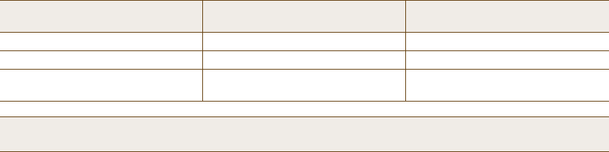
Office Requirements Expected Data Rate Using 802.11g
for Each Access Point
Access Point Density
Coverage (low capacity) 12 Mbps to 24 Mbps 1 access point per 8000 square feet
Standard office deployment36 Mbps 1 access point per 5000 square feet
Standard office deployment with
voice 54 Mbps 1 access point per 2000 – 3000 square
feet
Note: Data rate is not the same as TCP throughput. Because of various headers, inter-frame gaps, and session
creation, real TCP throughput usually does not exceed 22 Mbps at data rates of 54 Mbps.
Chapter 1 Preparing for a WLAN Deployment
16 Aerohive
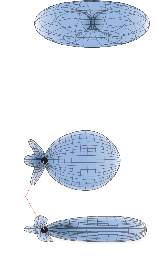
Figure 1 Omnidirectional Antenna Radiation Pattern
The HiveAP can accommodate external antennas via coaxial jacks on its chassis (see "Antennas" on page28).
The jack is a standard male RP-SMA connector. Various patch, directional, and omnidirectional antennas can be
used to change the coverage pattern. The most common external antennas are patch antennas. These are
directional antennas that provide coverage in a single direction. Most commonly they have a transmission
pattern as shown in Figure2. Based on the gain, the signal will be wide (like the low gain antenna shown on top)
or narrow and long (like the high gain antenna shown on the bottom). Note that the coverage patterns are not
perfect for these antennas and that they often broadcast slightly in other directions than the primary one.
These extra "lobes" can be seen in both of the patterns shown below.
Figure 2 Directional Antenna Patterns
The following are some quick hints for deploying access points:
•Standard sheetrock walls and dropped ceilings are the best locations for mounting access points.
•When deploying WLANs in retail stores, doing a site survey at each store is likely to be impractical. It is more
common to run detailed site surveys at a few locations and use the results to set up deployment guidelines for
the remaining sites.
•Be aware of metal-lined firewalls, steel pillars, and other metallic surfaces. RF signals can reflect off metal
surfaces, which can cause unexpected coverage patterns. Also watch out for objects that can block or reflect
signals, such as mirrors, plants, walls, steel doors, elevator shafts, and bathroom stalls.
Ø·¹¸»® Ù¿·²
Ô±©»® Ù¿·²
øÞ·®¼Ž- Û§» Ê·»©÷
п¬½¸
ß²¬»²²¿-
Ø·
¹
¸»® Ù¿·²
Deployment Guide 17
PLANNING
•The quality and performance of a Wi-Fi network is a function of the signal-to-noise ratio. To avoid noise issues,
check the area for common noise generators such as industrial microwave ovens, wireless video cameras,
cordless phones and headsets, and Bluetooth devices. Such devices especially cause interference in the 2.4 GHz
spectrum.
•Plan appropriately for high ceilings. With an omnidirectional antenna, the downward coverage is not great. In
normal office space, the ceilings rarely exceed 15 feet, so this issue does not come up very often. In
environments such as warehouses, where ceilings can be up to 50 feet high, ceiling-mounted access points are
not optimal. It is best to deploy them on non-metallic walls about 10 feet to 15 feet above the floor. If this is
not feasible, using patch antennas can help direct the RF energy downward.
•In high-density or high-capacity environments, placing access points on exterior walls allows for a greater
number of cells inside the building and more capacity. In other deployments, it is recommended that the outer
access points be no farther than 30 feet from the exterior walls to ensure coverage.
Preparing the Wired Network for Wireless
One of the advantages of moving to an Aerohive WLAN is that you do not have to make changes to the underlying
network, such as putting controllers into wiring closets. This can save you considerable time and effort during
installation. However, some network changes might make sense for some deployments. For example, you might
want to add additional VLANs or security settings. This section covers a few of the more common considerations
that IT departments are handling.
•802.1Q VLANs
HiveAPs can segment users into VLANs if an administrator wants. This decision can be made by a returned
RADIUS attribute or it can be configured as part of a user profile or SSID. Enterprises often set up separate
VLANs for wireless and guest access, so that this traffic is segmented from the rest of the network; however, it
is possible to set up any number of other VLANs for further segmentation. (For an example, see "Example 9:
Creating WLAN Policies" on page126.)
•Firewalls
Depending on the environment, enterprises might use firewalls to segment wired and wireless data. This can be
implemented as a discrete firewall enforcing traffic between VLANs or between ports, or you might use the
stateful firewall that is integrated in HiveOS (the HiveAP operating system).
•RADIUS Authentication
If RADIUS authentication is required, then a RADIUS server must be in place and be able to support the
necessary protocols for wireless—often called 802.1X EAP types: PEAP, EAP-TLS, EAP-TTLS, WEP 8021.x (dynamic
WEP), LEAP, EAP-FAST, and captive web portal authentication using CHAP.
•DNS and DHCP Configuration
If you use the Aerohive HiveManager (see the section on "Operational Considerations" on page18), it is possible
to install HiveAPs without any extra configuration and they will be able to contact HiveManager for
management. If the HiveAPs are linked to a different subnet than the one to which HiveManager is connected,
then you can set either a DHCP option or DNS entry to give the location of HiveManager (see "How HiveAPs
Connect to HiveManager" on page95).

Chapter 1 Preparing for a WLAN Deployment
18 Aerohive
OPERATIONAL CONSIDERATIONS
To make your WLAN deployment process as smooth as possible, you should consider more than just the distribution
and installation of access points. You should also consider how you will manage, optimize, and troubleshoot your
WLAN after deployment.
Tuning
Approach building an enterprise WLAN with the same life-cycle approach you would apply to a wired network. After
you deploy the WLAN, revisit key network engineering processes to account for changes in the environment. Watch
for access points that are overloaded or are under utilized, and check for potential dead spots. Furthermore, be
aware that the likely points of failure can change as the environment changes. For example, a neighboring business
might install access points that cause RF interference on your network. You should schedule and perform periodic
walkthroughs to ensure that the design goals of the wireless network continue to be met. The Aerohive HiveManager
provides quick views into how the network is behaving, which HiveAPs are the most heavily loaded, and which have
the most clients.
Troubleshooting
Some of the most common issues that arise after deploying a new wireless network are RF interference, RADIUS
issues, and desktop client issues. The first step in troubleshooting is to look at logs and use debug commands.
Aerohive offers an extensive set of event monitoring and debug tools that you can use through HiveManager, the
Aerohive network management system. For additional troubleshooting, particularly of clients or neighboring
networks, Aerohive recommends two tools: Ethereal Warehouser (http://www.wireshark.org/) and AirMagnet
Laptop Analyzer (http://www.airmagnet.com/products/laptop.htm).
Management
Current Wi-Fi networks typically span an entire company and have complex security policies. Fortunately, the
HiveManager Network Management System makes it simple to manage large networks from a central location. It
provides a single centralized management instance for the entire wireless network. While managed HiveAPs can
operate without HiveManager, it simplifies the provisioning of global policy management and centralized
configuration and monitoring. HiveManager lowers operating costs by speeding deployment, configuration, and
monitoring of the wireless network.
Managing faults and alarms is critical to maintaining uptime. You can view and manage events through HiveManager
logging. Optionally, you can use a third-party tool such as HP OpenView.
HiveManager makes it easy to monitor and troubleshoot HiveAPs within a WLAN infrastructure. HiveManager can
import hierarchical map views that represent the physical location of the network, from the perspective of the
entire world down to the floor level.
Deploying with Confidence
Moving a large enterprise—or even a small one—to a WLAN for the very first time need not be daunting. If you have
moderate experience with LAN deployments of other types and you have taken time to get answers to the important
questions that will affect the network data load, you have every prerequisite for success. The bottom line is to
remember to take stock of your project before you begin to ward against unforeseen costs and performance
bottlenecks. If you have considered the issues and guidelines presented here, you are not far away from a successful
Aerohive WLAN deployment.
Deployment Guide 19
BASIC WI-FI CONCEPTS
BASIC WI-FI CONCEPTS
The goal of this section is to provide some background on Wi-Fi propagation and how to lay out a wireless network.
While RF (radio frequency) engineering is a rather complicated science, this section provides a simple overview on
the basics of Wi-Fi propagation and channel layout that you need to be able to install an enterprise WLAN.
The first thing to know is that Wi-Fi is forgiving. Wi-Fi tends to transmit a bit farther than you expect, and even in
cases of interference, it tends to just work. This can be both a blessing and a curse. It is a blessing because people
will likely have access to the network, and it is a curse because your overall performance might be suboptimal
without obvious symptoms, like lack of connectivity. Understanding the basics presented in this section will help
ensure a high performance layout.
The first concept to understand is signal strength and how it relates to throughput. Radio power is measured in dBm
(decibels relative to one milliwatt) where 0 dBm = 1 milliwatt, but decibels increase using a log10 math function.
Rather than dusting off your old math books and pulling out your calculator, look at the dBm-to-milliwatt converter
that appears below. Often in Wi-Fi, dBm and milliwatts (mW)—and microwatts ( W)—are used interchangeably. The
following table converts between the two units of measurement.
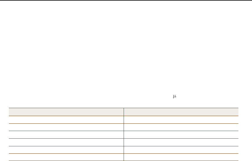
In RF, there is also a relative measurement that you can use to compare two numbers. This measurement is simply
dB (without the "m"). To see how this concept is applied, consider how radio signal propagation changes over a
distance and how it can be affected. Figure3 on page20 shows signal strength over distance as a curve that has the
best signal strength closer to the access point. It also shows noise. In general, noise is considered to be low-level
background RF signals that can interfere with a WLAN. This noise tends to be the garbled background RF that comes
from everything from the sun and stars to man-made interfering devices like Bluetooth headsets. It is impossible to
block out noise and it should not be attempted. This low level of background noise is called the "noise floor".
dBm-to-milliwatt
20 dBm = 100 mW 2 dBm = 1.6 mW
15 dBm = 32 mW 1 dBm = 1.3 mW
10 dBm = 10 mW 0 dBm = 1.0 mW
5 dBm = 3.2 mW -1 dBm = 794 µW
4 dBm = 2.5 mW -5 dBm = 316 µW
3 dBm = 2.0 mW -10 dBm = 100 µW
Chapter 1 Preparing for a WLAN Deployment
20 Aerohive
Figure 3 Path Loss in an Open Space
When clients send a packet, the ratio of the signal-to-noise (SNR) level defines the quality of the link, which is
directly related to the performance of the network. Based on the SNR, the client and AP negotiate a data rate in
which to send the packet, so the higher the SNR the better. For good performance, the SNR should be greater than
20 dB, and for optimal performance it should be at least 25 dB.
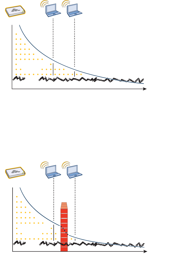
Signal strength not only diminishes over distance but it can also be affected by objects in the way (see Figure4).
This can be a wall, a tree, or even a person. There is a fairly predictable dB drop through most objects that also
decreases the SNR, thus decreasing the data rate. While this appears to be a bad thing, clever Wi-Fi installers use it
to their advantage. It allows them to place more access points in a tighter spot by using pre-existing walls and other
impediments to Wi-Fi propagation to keep them from interfering with each other.
Figure 4 Path Loss through a Wall
Í·¹²¿´ó¬±óÒ±·-»
ο¬·±
Ü·-¬¿²½»
Ò±·-»
λ½»·ª»¼ Í·¹²¿´
Í·¹²¿´ó¬±óÒ±·-»
ο¬·±
Ü·-¬¿²½»
Ò±·-»
λ½»·ª»¼ Í·¹²¿´
É¿´´
Deployment Guide 21
BASIC WI-FI CONCEPTS
Microwave ovens, wireless video cameras, Bluetooth headsets, and cordless phones can all interfere with Wi-Fi
signals (see Figure5). Excess noise in an environment is often difficult to diagnose and can have a major negative
impact on network performance. To discover noise sources, a spectrum analysis system is needed. AirMagnet
provides an affordable spectrum analysis tool that operates in the 2.4 GHz and 5 GHz spectra.
Figure 5 Path Loss with Noise (from Microwave)
Now that you have a sense of how Wi-Fi performance changes over distance and with noise, look at some ways to
perform channel assignment. If two access points are on the same channel right next to each other, they are forced
to share the same spectrum. This means that they share the 54 Mbps available in 802.11a/g rather than each being
capable of 54-Mbps speeds independently. This essentially halves the bandwidth for each access point. To manage
this situation, make sure that neighboring APs are on different channels and that their power is adjusted so that it
does not overlap that of other APs with the same channel.
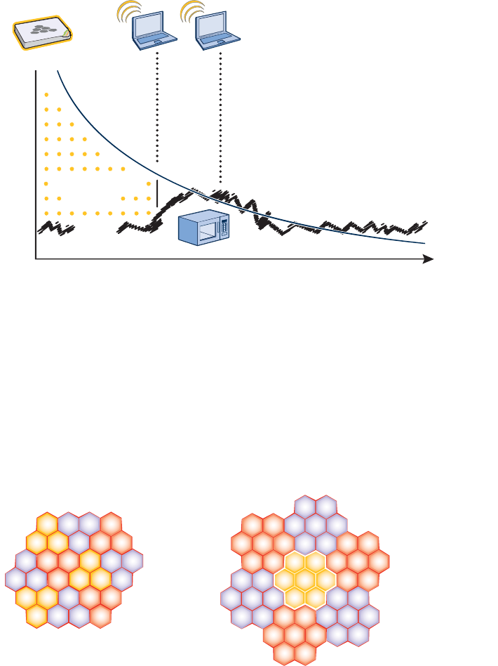
In the 2.4 GHz spectrum, there are 11 channels in the United States. However, a Wi-Fi signal consumes more than
one channel. Consequently, there are only 3 non-overlapping channels: 1, 6, and 11. To achieve optimal
performance, you need to design a channel layout pattern such as the one on the left in Figure6.
Figure 6 Channel Layout Patterns
Í·¹²¿´ó¬±óÒ±·-»
ο¬·±
Ü·-¬¿²½»
Ò±·-»
λ½»·ª»¼ Í·¹²¿´
êìêð
ëî
ëê
íê
ìì
ìð
êìêð
ëî
ëê
íê
ìì
ìð
êìêð
ëî
ëê
íê
ìì
ìð
êìêð
ëî
ëê
íê
ìì
ìð
êìêð
ëî
ëê
íê
ìì
ìð
êìêð
ëî
ëê
íê
ìì
ìð
êìêð
ëî
ëê
íê
ìì
ìð
éó¬±óï Ô¿§±«¬ שּׁ»®²
ïïê
ï
ïïê
ï
êï
ïï
êï
ïï
ïïï
ê ïïï
ê
êï
ïï
ê
ï
ïï
ïï
êï
íó¬±óï Ô¿§±«¬ שּׁ»®²
ïï
ê
ï
Chapter 1 Preparing for a WLAN Deployment
22 Aerohive
Designing a channel pattern is easier for the 5 GHz spectrum. Depending on the country and the device being used,
there are between 4 and 14 channels available for Wi-Fi use. However, in most countries there are at least 8 to work
with. To simplify the layout of more than 3 channels most use a 7-to-1 pattern, as is shown on the right in Figure6
on page21. This channel layout is much more flexible than the 3-channel system and allows for much better
capacity over all channels.
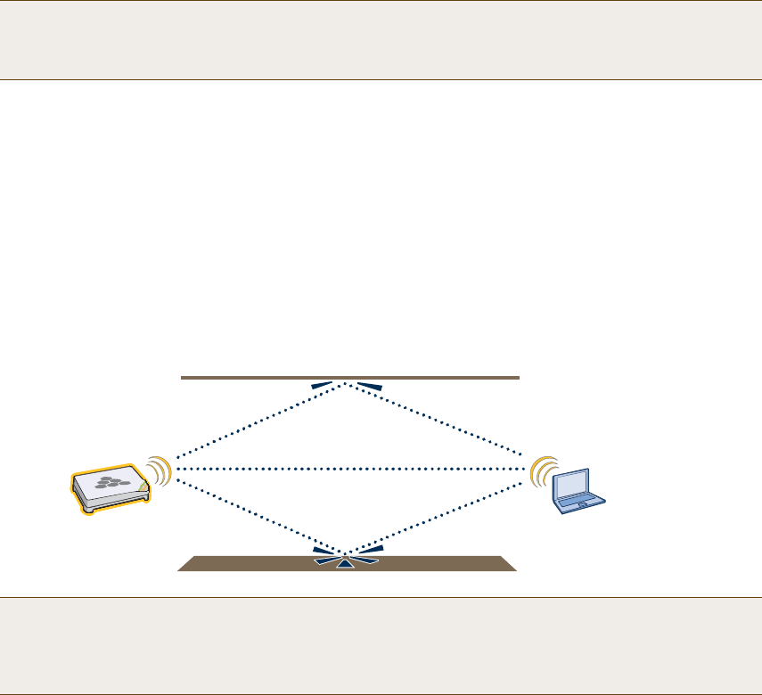
The last topic to cover is the concept of multipaths. When a client receives a transmission from an access point (or
vice versa), the RF signal reaches the client first through a "direct path," but then shortly thereafter by the "indirect
paths" reflected off other objects. The direct path combined with the indirect paths make up multipaths
(see Figure7). RF signals can bounce off of almost anything—walls, people, plants, and so on—but they bounce the
greatest off of metal. As the RF signals bounce about while propagating, one or more of the secondary paths can
interfere with the primary path, causing the signal strength of the direct path to diminish. In doing so, multipath
can greatly decrease signal to noise ratio.
Figure 7 Multipath Radio Waves
Note: There are alternative 2.4 GHz channel layouts, such as one for four channels using 1, 4, 8 and 11 and
another using channels 1, 5, 9 to counter interference from microwaves, which tend to cause interference
in the high end of the spectrum. Aerohive recommends alternative channel layouts only for the most
challenging radio environments.
Note: If you would like to learn more about how radio frequency propagation works or the details of 802.11,
Wikipedia provides excellent background information under the entries "IEEE 802.11", "radio propagation",
and "multipath". Additionally, spending a few hours with a site survey tool such as AirMagnet Surveyor and
a few test APs can increase both your familiarity with Wi-Fi propagation and your confidence about how it
behaves.
Ю·³¿®§ п¬¸
Í»½±²¼¿®§ п¬¸
Í»½±²¼¿®§ п¬¸
Deployment Guide 23
Chapter 2The HiveAP 20 ag Platform
The Aerohive HiveAP 20 ag is a new generation wireless access point. HiveAPs have the unique ability to
self-organize and coordinate with each other, creating a distributed-control WLAN solution that offers greater
mobility, security, quality of service, and radio control.
This guide combines product information, installation instructions, and configuration examples for both the HiveAP
and HiveManager platforms. This chapter covers the following topics relating to the HiveAP:
•"HiveAP 20 Product Overview" on page24
•"Ethernet and Console Ports" on page26
•"Status LEDs" on page27
•"Antennas" on page28
•"Mounting the HiveAP 20" on page29
•"Device, Power, and Environmental Specifications" on page31
Chapter 2 The HiveAP 20 ag Platform
24 Aerohive
HIVEAP 20 PRODUCT OVERVIEW
The HiveAP 20 ag is a multi-channel wireless AP (access point). It is compatible with IEEE 802.11b/g (2.4 GHz) and
IEEE 802.11a (5 GHz) standards and supports a variety of Wi-Fi (wireless fidelity) security protocols, including WPA
(Wi-Fi Protected Access) and WPA2.
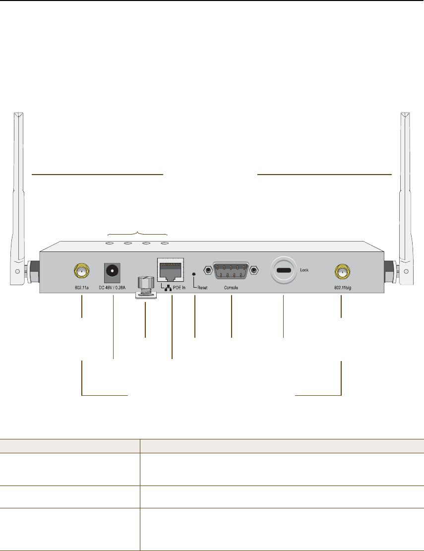
You can see the hardware components on the HiveAP in Figure1. Each component is described in Table1.
Figure 1 HiveAP 20 Hardware Components
Table 1 HiveAP 20 Component Descriptions
Component Description
Fixed Dual-Band AntennasThe two fixed omnidirectional dipole antennas can operate at two radio
frequencies: 2.4 GHz (for IEEE 802.11b/g) and 5 GHz (for IEEE 802.11a). For
details, see "Antennas" on page28.
Status LEDs The status LEDs convey operational states for system power, and the LAN,
Access, and Mesh interfaces. For details, see "Status LEDs" on page27.
802.11a RP-SMA Connector You can connect a detachable single-band antenna, such as the Pulse W1028
dipole antenna for the 5 GHz band, to the male 802.11a RP-SMA (reverse
polarity-subminiature version A) connector. Note that doing so disables the
adjacent fixed antenna.
Power
Connector
Mounting
Screw
10/100 Mbps
Power-over-
Ethernet Port
Reset
Button
Console
Port
Device
Lock Slot
Fixed Dual-Band Antennas
Connectors for Detachable Single-Band Antennas
Status LEDs
RP-SMA
Connector for
802.11a
Radio Antenna
RP-SMA
Connector for
802.11b/g
Radio Antenna

Deployment Guide 25
HIVEAP 20 PRODUCT OVERVIEW
Power Connector The 48-volt DC power connector (0.38 amps) is one of two methods through
which you can power the HiveAP 20. To connect it to a 100 – 240-volt AC
power source, use the AC/DC power adaptor that is available as an extra
option. Because the HiveAP does not have an on/off switch, connecting it to
a power source automatically powers on the device.
Mounting Screw To mount the HiveAP 20 on a surface, attach the mounting plate that ships
with the product to the HiveAP by inserting the two pins on the underside of
the chassis into slots in the plate and tightening the mounting screw. For
details, see "Mounting the HiveAP 20" on page29.
10/100 Mbps PoE Port The 10/100-Mbps Ethernet port supports IEEE 802.3af PoE (Power over
Ethernet) and receives RJ-45 connectors. The HiveAP can receive its power
through an Ethernet connection to power sourcing equipment (PSE) that is
802.3af-compatible. (If you connect the HiveAP to a power source through
the power connector and PoE port simultaneously, the device draws power
through the power connector and automatically disables PoE.)
The HiveAP can also connect to the wired network or to a wired device
(such as a security camera) through this port. It is compatible with
10/100Base-T/TX and automatically negotiates half- and full-duplex
connections with the connecting device. It is autosensing and adjusts to
straight-through and cross-over Ethernet cables automatically. It also
automatically adjusts for 802.3af Alternative A and B methods of PoE. For
details, see "Ethernet and Console Ports" on page26.
Reset Button The reset button allows you to reboot the device or reset the HiveAP to its
factory default settings. Insert a paper clip, or something similar, into the
Reset pinhole and press the reset button. To reboot the device, hold the
button down between 1 and 5 seconds. To return the configuration to the
factory default settings, hold it down for at least 5 seconds. After releasing
the button, the Power LED goes dark, and then glows steady amber while
the firmware loads and the system performs a self-test. After the software
finishes loading, the Power LED glows steady green.
To disable the reset button from resetting the configuration, enter this
command: no reset-button reset-config-enable Pressing the
button between 1 and 5 seconds will still reboot the HiveAP, but pressing it
for more than 5 seconds will not reset its configuration.
Console Port A male DB-9 serial port to which you can make a console connection using
an RS-232 (or "null modem") cable. The management station from which you
make a serial connection to the HiveAP must have a VT100 emulation
program, such as Tera Term Pro© (a free terminal emulator) or Hilgraeve
Hyperterminal® (provided with Windows® operating systems). The following
are the serial connection settings: bits per second: 9600, data bits: 8,
parity: none, stop bits: 1, flow control: none.
Device Lock SlotYou can physically secure the HiveAP by attaching a lock and cable (such as
a Kensington® notebook lock) to the device lock slot. After looping the cable
around a secure object, insert the T-bar component of the lock into the slot
on the HiveAP and turn the key to engage the lock mechanism.
802.11b/g RP-SMA ConnectorYou can connect a detachable single-band antenna, such as the Pulse W1038
dipole antenna for the 2.4 GHz band, to the male 802.11b/g RP-SMA
connector. Note that doing so disables the adjacent fixed antenna.
Component Description
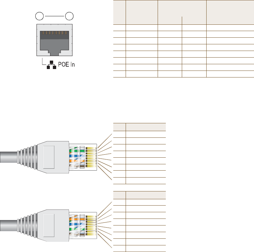
Chapter 2 The HiveAP 20 ag Platform
26 Aerohive
Ethernet and Console Ports
There are two ports on the HiveAP 20: a 10/100Base-T/TX Ethernet port and a male DB-9 console port. Both ports
use standard pin assignments.
The pin assignments in the PoE (Power over Ethernet) Ethernet port follow the TIA/EIA-568-B standard (see
Figure2). The PoE port accepts standard types of Ethernet cable—cat3, cat5, cat5e, or cat6—and can receive power
over this cable from power sourcing equipment (PSE) that is 802.3af-compatible. Such equipment can be embedded
in a switch or router, or it can come from purpose-built devices that inject power into the Ethernet line en route to
the HiveAP. Because the PoE port has autosensing capabilities, the wiring termination in the Ethernet cable can be
either straight-through or cross-over.
Figure 2 PoE Wire Usage and Pin Assignments
Pin T568A Wire Color
1White/Green
2Green
3White/Orange
4Blue
5White/Blue
6Orange
7White/Brown
8Brown
(View of the PoE port
on the HiveAP)
1 8
Pin Numbers
Pin T568B Wire Color
1White/Orange
2Orange
3White/Green
4Blue
5White/Blue
6Green
7White/Brown
8Brown
T568A-Terminated Ethernet Cable
with an RJ-45 Connector
802.3af Alternative A
(Data and Power on
the Same Wires)
802.3af Alternative B
(Data and Power on
Separate Wires)
Pin Data Signal MDI MDI-X MDI or MDI-X
1Transmit +DC+DC–– – –
2Transmit -DC+DC–– – –
3Receive +DC–DC+ – – –
4(unused) – – –– – –DC+
5(unused) – – –– – –DC+
6Receive -DC– DC+ – – –
7(unused) – – –– – –DC–
8(unused) – – –– – –DC–
MDI = Medium dependent interface for straight-through connections
MDI-X = Medium dependent interface for cross-over (X) connections
The PoE port is auto-sensing and can automatically adjust to transmit and receive data over straight-through or cross-over Ethe
rnet
connections. Likewise, it can automatically adjust to 802.3af Alternative A and B power delivery methods. Furthermore, when the
Alternative A method is used, the PoE port automatically allows for polarity reversals depending on its role as either MDI or M
DI-X.
T568B -terminated Ethernet Cable
with an RJ-45 Connector
T568A and T568B are two standard
wiring termination schemes. Note that
the only difference between them is
that the white/green + solid green pair
of wires and the white/orange + solid
orange pair are reversed.
For straight-through Ethernet
cables—using either the T568A or
T568B standard—the eight wires
terminate at the same pins on each
end.
For cross-over Ethernet cables, the
wires terminate at one end according
to the T568A standard and at the
other according to T568B.
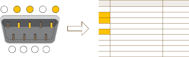
Deployment Guide 27
HIVEAP 20 PRODUCT OVERVIEW
The pin assignments in the male DB-9 console port follow the EIA (Electronic Industries Alliance) RS-232 standard. To
make a serial connection between your management system and the console port on the HiveAP, you can use a null
modem serial cable, use another serial cable that complies with the RS-232 standard, or refer to the pin-to-signal
mapping shown in Figure3 to make your own serial cable. Connect one end of the cable to the console port on the
HiveAP and the other end to the serial (or COM) port on your management system. The management system must
have a VT100 terminal emulation program, such as Tera Term Pro© (a free terminal emulator) or Hilgraeve
Hyperterminal® (provided with Windows® operating systems).
Figure 3 Console Port Pin Assignments
Status LEDs
The four status LEDs on the top of the HiveAP 20 indicate various states of activity through their color (dark, green,
amber) and illumination patterns (steady glow or blinking). The meanings of the various color + illumination
patterns for each LED are explained below.
Power
•Dark: No power
•Steady green: Powered on and the firmware is running normally
•Steady amber: Firmware is booting up or is being updated
•Blinking amber: Alarm indicating firmware failure
LAN
•Dark: Ethernet link is down or disabled
•Steady green: Ethernet link is up but inactive
•Blinking green: Ethernet link is up and active
Access
•Dark: Wireless link is disabled
•Steady green: Wireless link is up but inactive
•Blinking green: Wireless link is up and active
Mesh
•Dark: Wireless link is disabled
•Steady green: Wireless link is up but inactive
•Blinking green (fast): Wireless link is up and the HiveAP is searching for other hive members
•Blinking green (slowly): Wireless link is up and active
12345
6789
Pin Signal Direction
1DCD (Data Carrier Detect)(unused)
2RXD (Received Data)Input
3TXD (Transmitted Data)Output
4DTR (Data Terminal Ready)(unused)
5Ground Ground
6DSR (Data Set Ready)(unused)
7RTS (Request to Send)(unused)
8CTS (Clear to Send) (unused)
9RI (Ring Indicator) (unused)
Male DB-9 Console Port
(View of the console
port on the HiveAP)
The above pin assignments show a DTE (data terminal equipment)
configuration for a DB-9 connector complying with the RS-232 standard.
Because this is a console port, only pins 2,3, and 5 need be used.
RS-232 Standard Pin Assignments
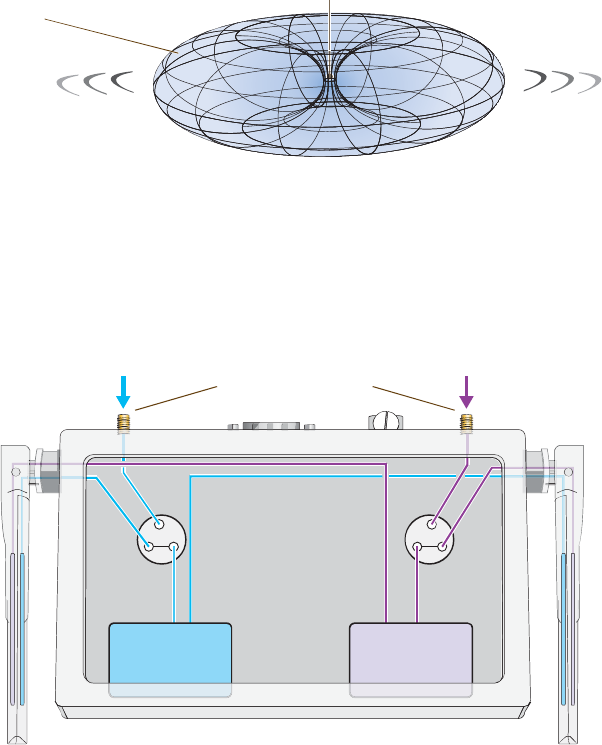
Chapter 2 The HiveAP 20 ag Platform
28 Aerohive
Antennas
The HiveAP 20 includes two fixed dual-band antennas with 3-dBi gains. These antennas are omnidirectional,
providing fairly equal coverage in all directions in a toroidal (donut-shaped) pattern around each antenna. When the
antennas are vertically positioned, coverage expands primarily on the horizontal plane, extending horizontally much
more than vertically. See Figure4, which shows the toroidal pattern emanating from a single vertically positioned
antenna. To change coverage to be more vertical than horizontal, position the antennas horizontally. You can also
resize the area of coverage by increasing or decreasing the signal strength.
Figure 4 Omnidirectional Radiation Pattern
The pair of fixed dual-band antennas operate concurrently in two different frequency ranges: 2.4GHz (IEEE
802.11b/g) and 5 GHz (IEEE 802.11a). Using two different frequency ranges reduces the probability of interference
that can occur when numerous channels operate within the same range. Conceptually, the relationship of antennas
and radios is shown in Figure5.
Figure 5 Antennas and Radios
\
After connecting an external antenna to an RP-SMA connector, you must enter the following command to move the
appropriate interface from the adjacent fixed antenna to the external antenna:
interface interface radio antenna external
Note: To show the shape of radiation more clearly,
this illustration depicts the coverage provided by
only one active antenna and is not drawn to scale.
The omnidirectional antennas
radiate equally in all directions,
forming a toroidal pattern.
HiveAP
Radio 1
RF 802.11b/g
2.4 GHz
Radio 2
RF 802.11a
5 GHz
Antenna
Switch 1
Antenna
Switch 2
RP-SMA Connectors
802.11a/b/g
Dual-Band
Fixed
Antenna
802.11a/b/g
Dual-Band
Fixed
Antenna
Cut-away view of the HiveAP to show the relationship
of the antennas and the two internal radios.
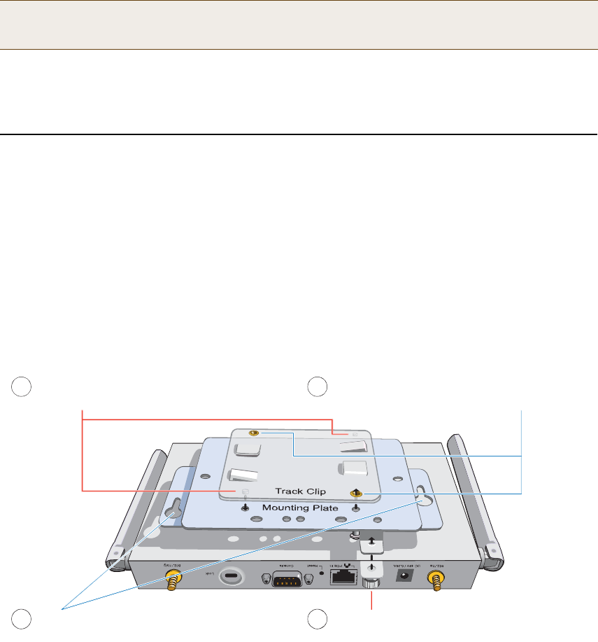
Deployment Guide 29
MOUNTINGTHE HIVEAP 20
The wifi0 interface links to radio 1 (frequency range = 2.4 GHz for IEEE 802.11b/g), and the wifi1 interface links to
radio2 (frequency range = 5 GHz for IEEE 802.11a). These interface-to-radio relationships are permanent. However,
the interface-to-antenna relationships can be shifted. In other words, you can change which antenna—fixed or
external—the wifi0 and wifi1 interfaces use. For example, to link the wifi0 interface to an external antenna
connected to the 802.11b/g RP-SMA connector (for radio 1), enter the following command:
interface wifi0 radio antenna external
If you do not enter this command, the wifi0 interface and all its subinterfaces (wifi0.1, wifi0.2, wifi0.3, and wifi0.4)
continue to use both fixed antennas.
To unlink the wifi0 interface from the external antenna and return it to the fixed antennas, enter this command:
interface wifi0 radio antenna internal
MOUNTINGTHE HIVEAP 20
Using the mounting plate and track clip, you can mount the HiveAP 20 to the tracks of a dropped ceiling grid. Using
just the mounting plate, you can mount the HiveAP to any surface that can support its weight (1.5 lb., 0.68 kg).
Ceiling Mount
To mount the HiveAP 20 to a track in a dropped ceiling, you need the mounting plate, track clip, and two cross-head
screws that ship with the track clip. You also need a cross-head screw driver and—most likely—a ladder.
Attach the track clip to the mounting plate, and then attach the clip-plate combination to the HiveAP 20, as shown
in Figure6.
Figure 6 Attaching the HiveAP 20 to the Mounting Plate and Track Clip
Note: After entering the above command, the radio to which you attached the external antenna uses the
external antenna and the fixed antenna on the opposite side of the HiveAP. Attaching an external antenna
only disconnects the adjacent fixed antenna. Note the two antenna switches shown in Figure5 on page28.
ß´·¹² ¬¸» ¬©± °®±¶»½¬·²¹ °±-¬- ±² ¬¸» «²¼»®-·¼» ±º
¬¸» ¬®¿½µ ½´·° ©·¬¸ ¸±´»- ·² ¬¸» ³±«²¬·²¹ °´¿¬»ò
Ë-·²¹ ¬¸» ¬©± ½®±--󸻿¼ -½®»©- ¬¸¿¬ -¸·° ©·¬¸ ¬¸»
¬®¿½µ ½´·°ô º¿-¬»² ¬¸» ³±«²¬·²¹ °´¿¬» ¬± ¬¸» ¬®¿½µ ½´·°ò
ײ-»®¬ ¬¸» °·²- ±² ¬¸» «²¼»®-·¼» ±º ¬¸» Ø·ª»ßÐ
·²¬± ¬¸» ¬©± -´±¬- ·² ¬¸» ³±«²¬·²¹ °´¿¬»ò
Ë-» ¬¸» ³±«²¬·²¹ -½®»© ¬± -»½«®» ¬¸» Ø·ª»ßÐ
¬± ¬¸» °´¿¬»ò
ï î
í ì
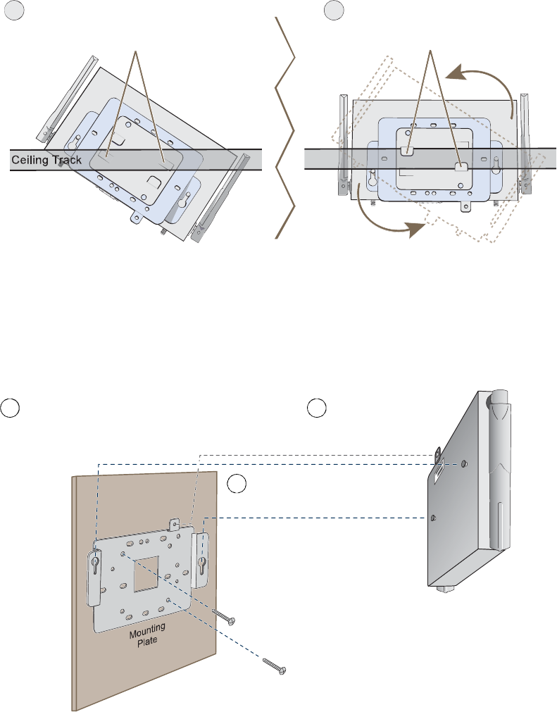
Chapter 2 The HiveAP 20 ag Platform
30 Aerohive
Nudge the ceiling tiles slightly away from the track to clear some space. Then attach the track clip to the ceiling
track as shown in Figure7. When done, adjust the ceiling tiles back into their former position.
Figure 7 Attaching the HiveAP to a Dropped Ceiling Track
Surface Mount
You can use the mounting plate to attach the HiveAP 20 to any surface that supports its weight, and to which you
can screw or nail the plate. First, mount the plate to the surface, and then attach the device to the plate, as shown
in Figure8.
Figure 8 Mounting the HiveAP on a Wall
Ю»-- ¬¸» ¬®¿½µ ½´·° ¿¹¿·²-¬ ¬¸» ½»·´·²¹ ¬®¿½µ -±
¬¸¿¬ ¬¸» ¬¸» ¬®¿½µ ½±²¬¿½¬- ¬¸» ¬©± °®»--«®» ¬¿¾-
¿²¼ °«-¸»- ¬¸»³ º´«-¸ ©·¬¸ ¬¸» ¬®¿½µ ½´·°ò
ન¬» ¬¸» Ø·ª»ßÐ ¿²¼ ¬¸» ³±«²¬·²¹
¿½½»--±®·»- ¿¬¬¿½¸»¼ ¬± ·¬ «²¬·´ ¬¸» ¬©±
½´·°°·²¹ ¬¿¾- ¹®·° ¬¸» ½»·´·²¹ ¬®¿½µò
ë ê
ø¾·®¼Ž- »§» ª·»©
©·¬¸ ½»·´·²¹ ¬·´»-
®»³±ª»¼ º±® ½´¿®·¬§÷
Use the mounting screw
to secure the HiveAP 20
to the plate.
Insert the pins on the underside of
the HiveAP 20 into the two slots.
With the two wings at the sides of the plate extending
away from the surface, attach the mounting plate to a
secure object such as a wall, ceiling, post, or beam.
1
2
3
Note: There are a variety of holes through which you can
screw or nail the plate in place. Choose the two or three
that best suit the object to which you are attaching it.

Deployment Guide 31
DEVICE, POWER,AND ENVIRONMENTAL SPECIFICATIONS
DEVICE, POWER,AND ENVIRONMENTAL SPECIFICATIONS
Understanding the range of specifications for the HiveAP 20 is necessary for optimal deployment and device
operation. The following specifications describe the physical features and hardware components, the power adapter
and PoE (Power over Ethernet) electrical requirements, and the temperature and humidity ranges in which the
device can operate.
Device Specifications
•Chassis dimensions: 8 1/4" W x 1" H x 4 15/16" D (21 cm W x 2.5 cm H x 12.5 cm D)
•Weight: 1.5 lb. (0.68 kg)
•Antennas: Two fixed dual-band 802.11a/b/g antennas, and two RP-SMA connectors for detachable single-band
802.11a or 802.11b/g antennas
•Serial port: DB-9 (bits per second: 9600, data bits: 8, parity: none, stop bits: 1, flow control: none)
•Ethernet port: autosensing 10/100Base-T/TX Mbps, with IEEE 802.3af-compliant PoE (Power over Ethernet)
Power Specifications
•AC/DC power adapter:
•Input:100 – 240 VAC
•Output: 48V/0.38A
•PoE nominal input voltages: 48 V, 0.35A
•RJ-45 power input pins: Wires 4, 5, 7, 8 or 1, 2, 3, 6
Environmental Specifications
•Operating temperature: 32 to 122 degrees F (0 to 50 degrees C)
•Storage temperature: -4 to 158 degrees F (-20 to 70 degrees C)
•Relative Humidity: Maximum 95%
Chapter 2 The HiveAP 20 ag Platform
32 Aerohive

Deployment Guide 33
Chapter 3The HiveAP 28 Outdoor Platform
The Aerohive HiveAP 28 is a new generation wireless access point that is customized for outdoor use. It is mountable
in any direction and on any hard surface, post, or wire strand. It can receive power either through an Ethernet cable
or power cord.
This guide combines product information, installation instructions, and configuration examples for both the HiveAP
and HiveManager platforms. This chapter covers the following topics relating to the HiveAP 28:
•"HiveAP 28 Product Overview" on page34
•"Ethernet Port" on page35
•"Power Connector" on page36
•"Antennas" on page37
•"Mounting the HiveAP 28 and Attaching Antennas" on page38
•"Pole Mount" on page39
•"Strand Mount" on page40
•"Surface Mount" on page41
•"Attaching Antennas" on page42
•"Device, Power, and Environmental Specifications" on page44
Note: Do not open the HiveAP 28 chassis. There are no serviceable parts inside.
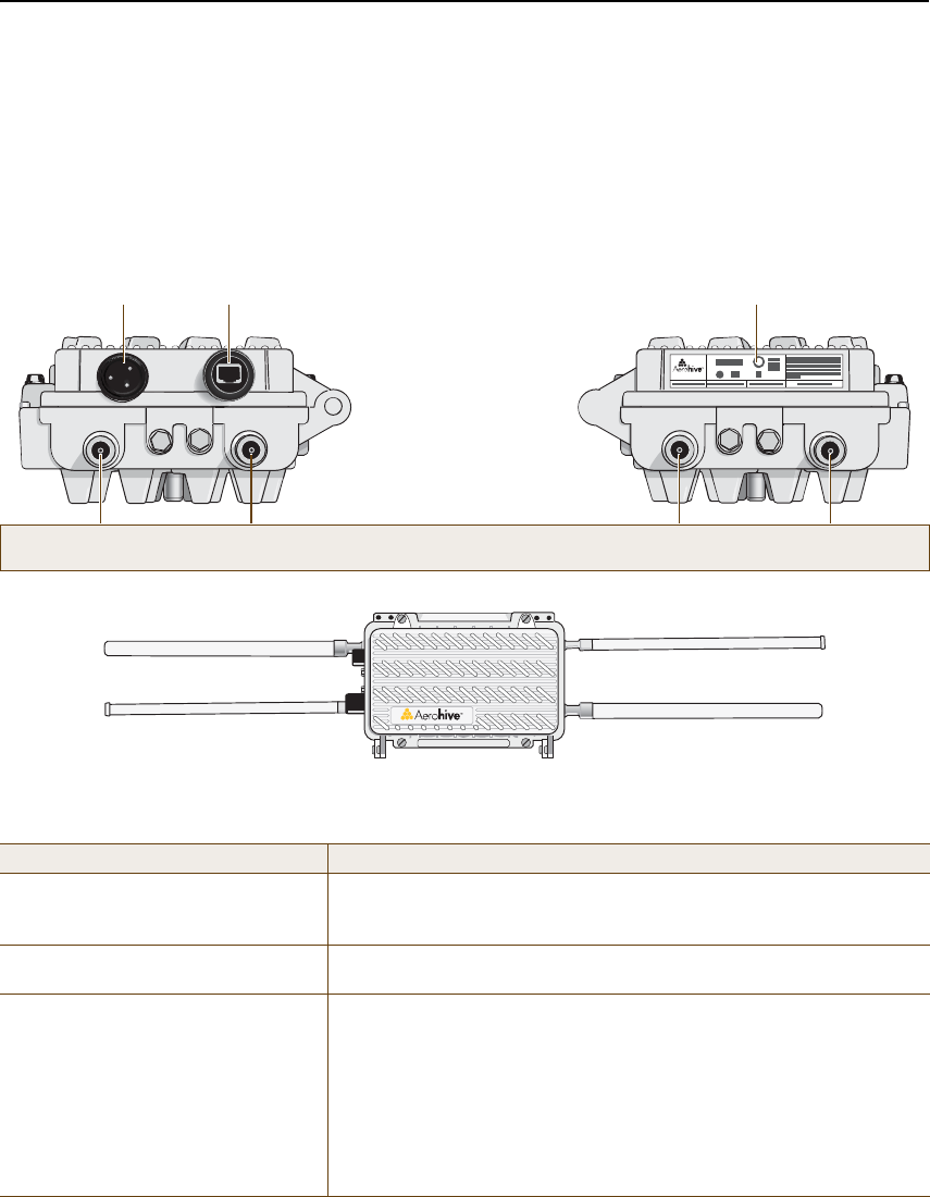
Chapter 3 The HiveAP 28 Outdoor Platform
34 Aerohive
HIVEAP 28 PRODUCT OVERVIEW
The HiveAP 28 is a multi-channel wireless AP (access point) for outdoor use. It is compatible with IEEE 802.11b/g
(2.4 GHz) and IEEE 802.11a (5 GHz) standards and supports a variety of Wi-Fi (wireless fidelity) security protocols,
including WPA (Wi-Fi Protected Access) and WPA2.
You can see the hardware components on the HiveAP 28 in Figure1. Each component is described in Table1.
Figure 1 HiveAP 28 Hardware Components
Table 1 HiveAP 28 Component Descriptions
Component Description
Detachable Single-Band AntennasThe two pairs of detachable omnidirectional dipole antennas operate at
two radio frequencies: one pair at 2.4 GHz (for IEEE 802.11b/g) and the
other at 5 GHz (for IEEE 802.11a). For details, see "Antennas" on page37.
Type N Connectors (Female)Attach antennas to the HiveAP 28 through these connectors. For details,
see "Attaching Antennas" on page42.
Waterproof Power ConnectorUsing the power connector is one of two methods through which you can
power the HiveAP 28. To connect it to a 100 – 240-volt AC power source,
use the power cable that ships with the product as an extra option.
Because the HiveAP does not have an on/off switch, connecting it to a
power source automatically powers on the device. The power source
must have a readily accessible service disconnect switch incorporated
into the fixed wiring installation so that you have the ability to turn the
power on and off. (The other method that the HiveAP can obtain power is
through its PoE port.)
ë Ùئ îòì Ùئ ë Ùئ îòì Ùئ
Power
Connector
10/100 Mbps
Power-over-
Ethernet Port
Type N female connectors for
detachable single-band antennas
For the 802.11a
Radio Antenna
For the 802.11b/g
Radio Antenna
For the 802.11a
Radio Antenna
For the 802.11b/g
Radio Antenna
FCC Compliance Label
(Plus model, serial number, MAC
address, and FCC ID number)
802.11a Main Antenna (5 GHz) 802.11b/g Main Antenna (2.4 GHz)
802.11b/g Auxiliary Antenna (2.4 GHz) 802.11a Auxiliary Antenna (5 GHz)
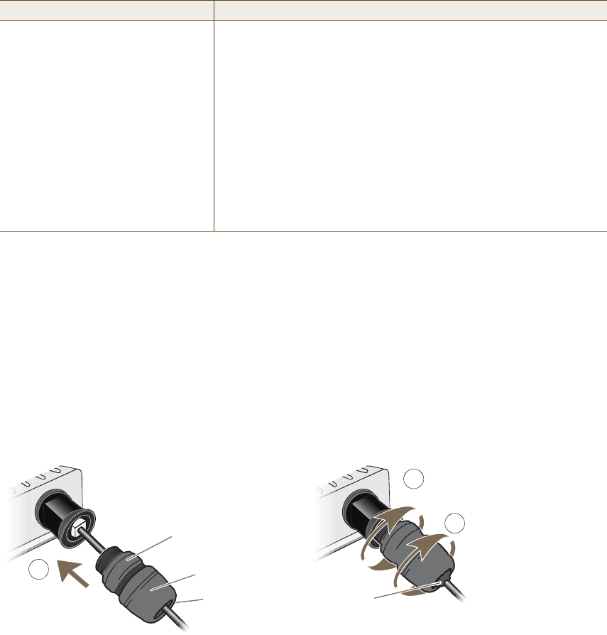
Deployment Guide 35
HIVEAP 28 PRODUCT OVERVIEW
Ethernet Port
The HiveAP 28 has a 10/100Base-T/TX PoE (Power over Ethernet) port. Its pin assignments follow the TIA/EIA-568-B
standard (see Figure2 on page26). The PoE port accepts standard types of Ethernet cable—cat3, cat5, cat5e, or
cat6—and can receive power over this cable from power sourcing equipment (PSE) that is 802.3af-compatible. Such
equipment can be embedded in a switch or router, or it can come from purpose-built devices that inject power into
the Ethernet line en route to the HiveAP. Because the PoE port has autosensing capabilities, the wiring termination
in the Ethernet cable can be either straight-through or cross-over (MDI/MDI-X). For outdoor deployments use
weatherproofed shielded twisted pair (STP) Ethernet cables.
To ensure a waterproof seal for the Ethernet connection, use the RJ-45 connector assembly, which comes in three
parts: a compression nut, end cap, and gasket.
Figure 2 Connecting the Ethernet Cable
1.Insert one end of the Ethernet cable through the waterproof RJ-45 connector assembly and plug the cable into
the Ethernet port.
2.Tighten the compression nut by twisting it clockwise into the Ethernet port housing on the chassis.
3.Tighten the end cap by twisting it clockwise onto the compression nut and tighten until the rubber gasket
emerges and wrap itself around the Ethernet cable.
The Ethernet connection is now sealed and waterproof.
10/100 Mbps PoE Port The 10/100-Mbps Ethernet port supports IEEE 802.3af PoE (Power over
Ethernet) and receives RJ-45 connectors. The HiveAP can receive its
power through an Ethernet connection to PSE (power sourcing
equipment) that is 802.3af-compatible. (If you connect the HiveAP to a
power source through the power connector and PoE port simultaneously,
the device draws power through the power connector and automatically
disables PoE.)
The HiveAP 28 can also connect to the wired network or to a wired device
(such as a security camera) through this port. It is compatible with
10/100Base-T/TX and automatically negotiates half- and full-duplex
connections with the connecting device. It is autosensing and adjusts to
straight-through and cross-over Ethernet cables automatically
(MDI/MDI-X). It also automatically adjusts for 802.3af Alternative A and B
methods of PoE. For details, see "Ethernet Port".
Component Description
î
ݱ³°®»--·±² Ò«¬
Û²¼ Ý¿°
Ù¿-µ»¬
ø·²-·¼»÷
Ù¿-µ»¬
ø-¯«»»¦»¼ ±«¬÷
ï
í
Slide the Ethernet cable through the two
halves of the waterproof RJ-45 connector
assembly, screw the halves loosely together,
and then plug the cable into the Ethernet port.
Tighten the compression nut
into the Ethernet port housing
on the chassis.
Tighten the end cap until
the gasket is squeezed out
the opening and forms a
watertight seal around the
cable.

Chapter 3 The HiveAP 28 Outdoor Platform
36 Aerohive
4.Connect the other end of the Ethernet cable to PSE (power sourcing equipment), such as a power injector, if the
HiveAP 28 receives power through PoE, or directly to a network device, such as a switch, if it receives power
through a power cord.
If the Ethernet cable connects the HiveAP to another device that is indoors, you must install appropriate
lightning protection at the point before it enters the building. Failing to do so might cause damage to the
equipment as well as serious injury or death.
Power Connector
The HiveAP 28 can receive power through an Ethernet cable using PoE or through a power cord. Aerohive
recommends using either PoE or wiring the power cord directly to a 100 – 240-volt AC power source. Only plug the
power cord into an electric outlet when configuring the device before deployment or when testing it in the lab.
To connect the power cord to the HiveAP 28:
1.Align the slot in the power cord plug with the small tab at the top of the three-pin power connector, and slide
the plug firmly over the pins until it is fully seated in the power connector.
2.Slide the cover over the connector and tighten it by turning the cover clockwise.
3.Install a lightning protector between the HiveAP 28 and its power source.
4.When possible, run the cord through a conduit to protect it from the elements. Where the cord is exposed,
allow enough slack in it to create a drip loop. Leaving some slack in the cord lets water run away from the
connections at each end. Use only a weatherproof power cord, such as the cord that ships with the HiveAP 28.
5.Strip the other end of the power cord and wire it directly to a power source, such as a junction box that has a
service disconnect switch that you can use to turn the power on and off. Also, because the HiveAP 28 does not
have short-circuit (over current) protection built into it, it relies on the protection provided by the power
source to which you connect it. Ensure that the protective device, such as a circuit breaker, is not rated greater
than 15A. Furthermore, if you need to install the HiveAP 28 in a wet or damp location, the AC branch circuit
that is powering it must be provided with ground fault protection (GFCI), as required by Article 210 of the
National Electrical Code (NEC).
Note: To prevent damage to the HiveAP 28 or power injector when using PoE to provide power, connect the
Ethernet cable from the power injector to the HiveAP 28, and connect the injector to a power jack
before applying power.
Note: When the HiveAP acts as a mesh point and does not use the Ethernet port, cover the Ethernet port with a
connector cap to prevent water intrusion and possible safety hazards.
Note: When the HiveAP receives power through PoE, cover the power connector with a connector cap to prevent
water intrusion and possible safety hazards.
Note: The HiveAP 28 must be grounded. Do not operate it unless there is a suitably installed ground
conductor. Contact the appropriate electrical inspection authority or an electrician if you are
uncertain that suitable grounding is available.
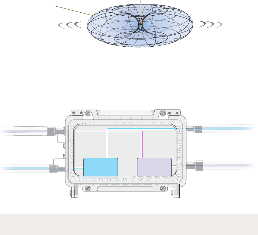
Deployment Guide 37
HIVEAP 28 PRODUCT OVERVIEW
Antennas
The HiveAP 28 includes two detachable single-band antennas with 8dBi gains (802.11b/g) and two detachable
single-band antennas with 10dBi gains (802.11a). These antennas are omnidirectional, providing fairly equal
coverage in all directions in a toroidal (donut-shaped) pattern around each antenna. When the antennas are
vertically positioned, coverage expands primarily on the horizontal plane, extending horizontally much more than
vertically. See Figure3, which shows the toroidal pattern emanating from a single vertically positioned antenna.
Note that when high gain antennas are added, the torus shape becomes somewhat elongated or compressed. If the
HiveAP 28 is mounted higher than 20 feet the center of the torus curves inward so that the connection quality,
directly underneath the center of the HiveAP 28, becomes compromised.
To change coverage to be more vertical than horizontal, position the HiveAP so that the antennas are on a
horizontal plane. You can also resize the area of coverage by increasing or decreasing the signal strength.
Figure 3 Omnidirectional Radiation Pattern
The pairs of antennas operate concurrently in two different frequency ranges: 2.4GHz (IEEE 802.11b/g) and 5 GHz
(IEEE 802.11a). Using two different frequency ranges reduces the probability of interference that can occur when
numerous channels operate within the same range. Conceptually, the relationship of antennas and radios is shown in
Figure4. (For information about attaching the antennas to the HiveAP 28, see "Attaching Antennas" on page42.)
Figure 4 Antennas and Radios
\
Note: The HiveAP 20 uses interface interface radio antenna external command to enable an
external antenna attached to it. Entering this command on the HiveAP 28 disables the antenna on the
opposite side of the device from the radio to which the interface is linked and results in a loss of diversity.
Note: To show the shape of radiation more clearly,
this illustration depicts the coverage provided by
only one active antenna and is not drawn to scale.
The omnidirectional antennas
radiate equally in all directions,
forming a toroidal pattern.
HiveAP
The two 802.11b/g antennas link internally to Radio 1
and broadcast in the 2.4 GHz frequency range.
802.11a Main Antenna 802.11b/g Main Antenna
802.11b/g Auxiliary Antenna 802.11a Auxiliary Antenna
The two 802.11a antennas link internally to Radio 2
and broadcast in the 5 GHz frequency range.
Radio 1
RF 802.11b/g
2.4 GHz
Radio 2
RF 802.11a
5 GHz

Chapter 3 The HiveAP 28 Outdoor Platform
38 Aerohive
MOUNTINGTHE HIVEAP 28 AND ATTACHING ANTENNAS
Using the mounting accessories (available separately) you can mount the HiveAP in various locations:
•"Pole Mount" on page39 – Mount the HiveAP 28 on a pole such as a street light.
•"Strand Mount" on page40 – Suspend the HiveAP 28 from a cable or phone line.
•"Surface Mount" on page41 – Mount the HiveAP 28 on a flat surface such as a wall or beam.
You can mount the HiveAP 28 in any of these locations as long as the object to which you mount it and the attaching
screws can support its weight (9 lbs., 4.08 kg).
After mounting the HiveAP 28, attach the antennas as explained in "Attaching Antennas" on page42.
Before you mount the HiveAP 28 and attach antennas, read the following warnings and cautions:
•To install the HiveAP 28, you must be a qualified installation professional, licensed or certified in
accordance with local regulations.
•Use lightning arrestors and ground both the HiveAP 28 and any separately mounted antennas.
•Do not connect or disconnect antennas or cables from the HiveAP 28 during periods of lightning activity.
•If you need to place the HiveAP 28 in an explosive environment, such as in an oil refinery, mine, or any
place where there is flammable gas, it must first be encased in an ATEX enclosure.
•To comply with RF (radio frequency) exposure limits, do not place antennas within 6.56 feet (2 meters) of
people.
•Do not locate antennas near overhead power lines or other electric light or power circuits, or where they
can come into contact with such circuits. When installing antennas, take extreme care not to come into
contact with these circuits, which might cause serious injury or death. For proper installation and grounding
of the antenna, refer to national and local electrical codes: NFPA (National Fire Protection Association) 70,
National Electrical Code Article 810 (U.S.); Canadian Electrical Code, Part I, CSA 22.1 and Section 54
(Canada); and if local or national electrical codes are not available, refer to IEC (International
Electrotechnical Commission) 364, Part 1 through 7 (other countries).
•To prevent damage, avoid over-tightening the connectors, nuts, and screws used to mount the HiveAP 28
and antennas.
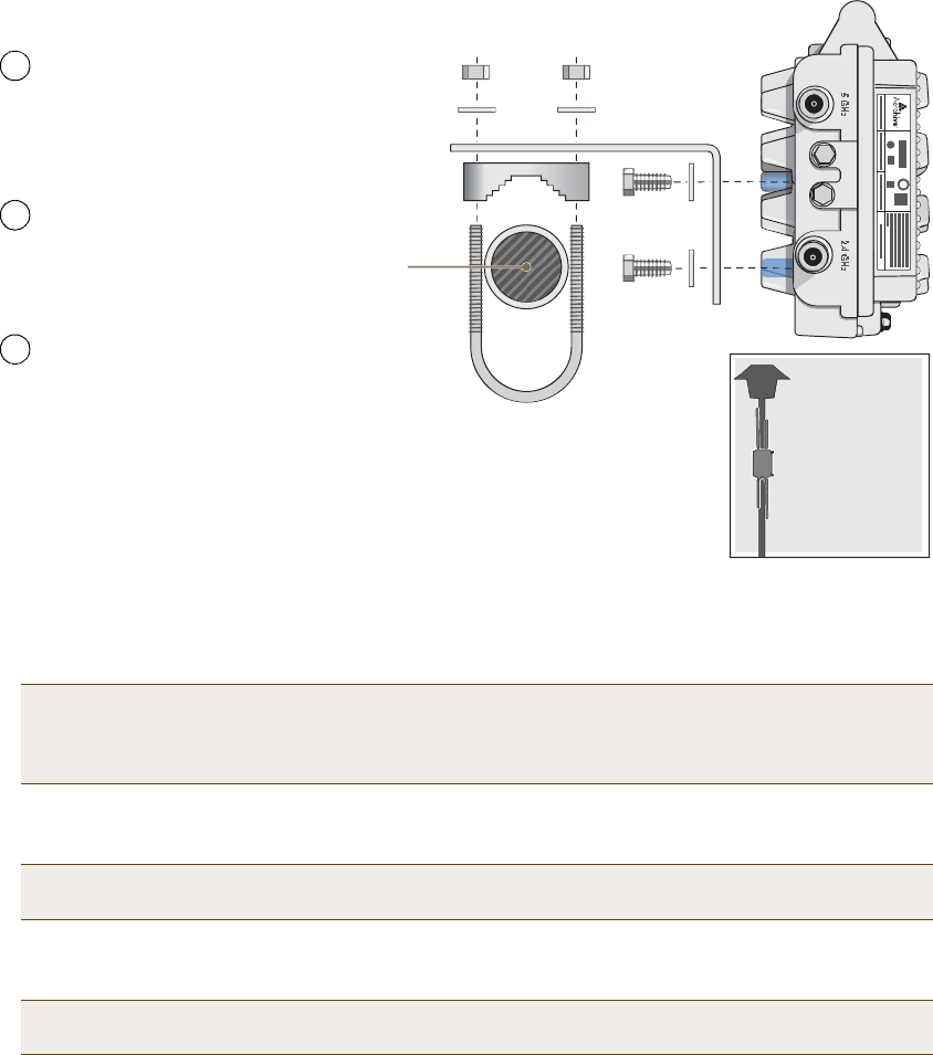
Deployment Guide 39
MOUNTINGTHE HIVEAP 28 AND ATTACHING ANTENNAS
Pole Mount
To mount the HiveAP 28 to a pole with a 1.5-inch diameter, you need two sets of the L-shaped brackets, two 2"
U-bolts, saddle clamps, and the nuts, bolts, and washers shown in Figure5. You also need a wrench to tighten the
nuts and bolts securely.
Figure 5 Attaching the HiveAP 28 to a Pole
1.Align two of the holes in the shorter end of the bracket with two of the holes in the HiveAP, insert the two bolts
through the washers and bracket, and screw them into the holes in the HiveAP 28 chassis, using a wrench to
tighten the bolts so that the bracket is securely attached.
2.Holding a saddle clamp against the inside of the long end of one of the L-shaped brackets, slip a U-bolt around
the pole and thread it through the two holes in the saddle clamp and L-shaped bracket.
3.Thread a split washer and 5/16-18 nut to each end of the U-bolt, and tighten them with a wrench to secure the
U-bolt firmly to the pole.
Note: Repeat this step to attach the other bracket to the HiveAP. However, this time, place the long end of
the bracket in the opposite direction of the first one for better stability. For example, if you attached
the first bracket with its long end positioned toward the outside edge of the device, install this second
bracket with the long end of the bracket toward the middle.
Note: One of the holes in the bracket is arc-shaped so that you can adjust the angle of the mounted device if
necessary.
Note: Repeat steps 2 and 3 to attach the other U-bolt and saddle clamp to the remaining L-shaped bracket
and secure the HiveAP 28 to the pole.
Í¿¼¼´» Ý´¿³°
Ê»®¬·½¿´ б´»
øïòëŒ ¼·¿³»¬»®÷
îŒ ËóÞ±´¬
Í°´·¬ É¿-¸»®-
ëñïêóïè Ò«¬-
Ôó͸¿°»¼ Þ®¿½µ»¬
ïñìóîð Þ±´¬-
¿²¼
Í°´·¬ É¿-¸»®-
Þ·®¼Ž-óÛ§» Ê·»©
Í·¼» ª·»© ±º ¬¸»
Ø·ª»ßÐ îè
³±«²¬»¼ ¬± ¿
-¬®»»¬ ´·¹¸¬
Note: For clarity, only one post mounting
set is shown in the illustration. You also
need to use a second set to finish mounting
the HiveAP on a pole.
Use the 1/4-20 bolts and split
washers to attach the shorter end of
the L-shaped bracket to holes in the
underside of the HiveAP 28.
Slip the U-bolt around the pole and
thread its ends through the saddle
clamp and L-shaped bracket.
Thread the split washers and
5/16-18 nuts over the ends of the
U-bolt and tighten until the bracket
assembly and device are secured to
the pole.
1
2
3
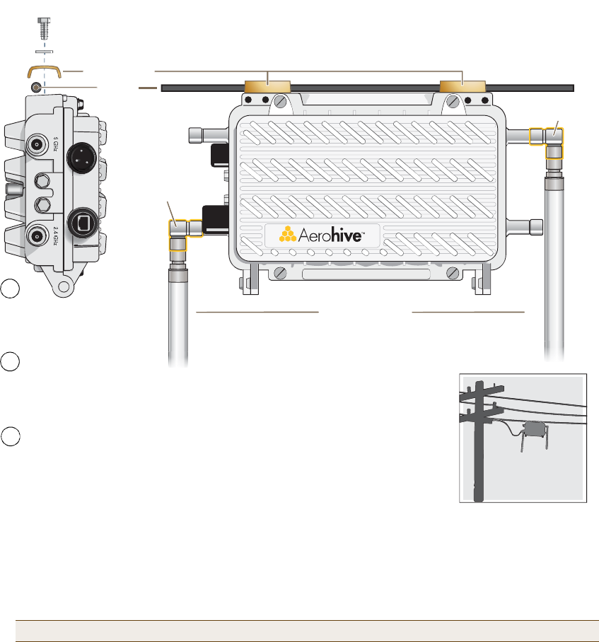
Chapter 3 The HiveAP 28 Outdoor Platform
40 Aerohive
Strand Mount
The HiveAP 28 outdoor platform can also be mounted on a cable or strand of wire as shown in Figure6. When
mounted on a wire strand, use 90-degree N type adapters (not included) to orient the antennas vertically. If you do
not use the adapters and orient the antennas horizontally, the area covered will be far less.
Figure 6 Clamping the HiveAP 28 to a Wire Strand
To mount the HiveAP 28 on a wire or strand, you need a wrench and two 1/4-20 bolts, split washers, strand clamps,
and 90-degree type N adapters. In the following instructions, you use only the 2.4 GHz antennas.
1.Position the HiveAP 28 so that its long side (with three holes at each end) is underneath a cable or wire strand
running lengthwise along the upper side of the chassis (for the proper orientation, see the inset in Figure6).
2.Place the strand clamp over the wire and use the 1/4-20 bolt and split washer to secure the strand between the
clamp and chassis.
3.Attach the 90-degree type N adapters to the two 2.4 GHz antenna connectors and then attach the antennas to
the adapters so that the antennas face downward. For details, see "Attaching Antennas" on page42.
Note: Repeat the preceding steps to fasten the other end of the HiveAP 28 to the cable or wire strand.
ͬ®¿²¼ Ý´¿³°
Í°´·¬ É¿-¸»®
ͬ®¿²¼
ïñìóîð Þ±´¬
Û²¼ Ê·»©
Í·¼» Ê·»©
Í·¼» ª·»© ±º ¬¸»
Ø·ª»ßÐ îè ³±«²¬»¼
±² ¿ ½¿¾´» -¬®¿²¼
çðóÜ»¹®»»
̧°» Ò ß¼¿°¬»®
çðóÜ»¹®»»
̧°» Ò ß¼¿°¬»®
îòì Ùئ ß²¬»²²¿-
Note: For clarity, only one bolt, washer,
and strand clamp are shown in the
illustration on the left. You also need to use
a second set of these items to finish
clamping the HiveAP to a wire strand.
Position the HiveAP 28 so that
its long side is directly beneath
a cable or wire strand.
Place the strand clamps over the
wire, and bolt the clamps tightly to
the chassis around the strand.
1
2
Attach 90-degree type N adapters to the
2.4 GHz antenna connectors so that the
adapters face downward, and then
attach the antennas to the adapters
3
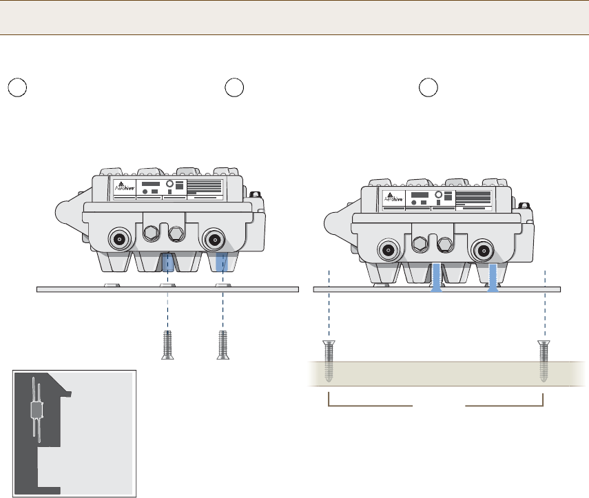
Deployment Guide 41
MOUNTINGTHE HIVEAP 28 AND ATTACHING ANTENNAS
Surface Mount
You can use the mounting plate to attach the HiveAP 28 to any surface that supports its weight (9 lbs., 4.08 kg), and
to which you can screw or nail the plate. First, mount the plate to the HiveAP 28, and then attach the plate to the
surface, as shown in Figure7. Note that the screw heads that you attach to the wall or surface must be small
enough for the keyholes on the mounting plate to slip over them.
Figure 7 Mounting the HiveAP 28 on a Wall
To mount the HiveAP 28 to a surface like a wall, you need two mounting plates, four 1/4-20 x 1/2" flat head screws,
four screws (no bigger than 5/16"), and a screw driver:
1.Align the ridged edge of one of the mounting plates with two of the holes located on the underside of the
HiveAP 28, and use two 1/4-20 x 1/2" flat head screws to secure the plate against the HiveAP 28. Then attach
the other mounting plate to the HiveAP 28 in the same way.
2.Attach four 5/16" screws to a wall or beam. They must be 8 1/8" (206 mm) apart vertically and 7 7/8" (200 mm)
apart horizontally to accommodate the keyholes on the mounting plates.
3.Guide the keyholes over the screws fastened to the wall and push downward after the screw heads have cleared
the keyholes.
Note: Because the metal in a wall can degrade the radio signal pattern, Aerohive recommends using sector
antennas instead of omnidirectional antennas when mounting the device on a wall.
ë Ùئ îòì Ùئ
é éñèŒ
îðð ³³
̱° ±º É¿´´
ë Ùئ îòì Ùئ
Ó±«²¬·²¹ д¿¬»
ïñìóîð ¨ ïñîŒ
Ú´¿¬ Ø»¿¼ ͽ®»©-
Þ·®¼Ž-óÛ§» Ê·»©
Í·¼» ª·»© ±º ¬¸»
Ø·ª»ßÐ îè ³±«²¬»¼
±² ¿² »¨¬»®·±® ©¿´´
Guide the screws fastened to
the wall through the keyholes
in the mounting plates.
Attach four screws to a secure object
such as a wall or beam. Space them
81/8" (206 mm) apart vertically and
77/8" (200 mm) apart horizontally.
With the ridged edge of the holes on the
mounting plates facing the HiveAP 28, use
1/4-20 x 1/2 inch screws to secure the two
mounting plates to its underside.
1 2 3
Note: For clarity, only one mounting plate is shown in the illustration.
You also need a second plate with another set of screws.

Chapter 3 The HiveAP 28 Outdoor Platform
42 Aerohive
Attaching Antennas
You can connect the antennas directly to the HiveAP 28 or mount them separately. Although connecting the
antennas directly to the device typically provides better performance, in some cases the location of the HiveAP
might not be a good location for the antennas; for example, if the HiveAP 28 is mounted on a reinforced concrete
wall that interferes with radio coverage. In such cases, mounting the antennas separately in a more open location
can improve coverage; however, bear in mind that cables introduce loss into the overall signal strength and that the
longer the cable connecting the antennas to the HiveAP 28, the greater the loss will be.
Connecting Antennas Directly to the HiveAP 28
The two 2.4 GHz and two 5 GHz antennas that ship with the HiveAP 28 have male Type N connectors that you can
connect directly to the female Type N antenna connectors on the HiveAP 28. You can also use self-amalgamating
PTFE (polytetrafluoroethylene) tape, which is available separately from Aerohive, to create a waterproof seal at the
points of attachment.
To attach the antennas:
1.Remove the antenna connector covers from the HiveAP 28 (leave the covers on any connectors that you do not
plan to use), and make sure that the surface of the connectors on the HiveAP 28 and the connectors on the
antennas are clean.
2.If you are using PTFE tape, wrap the tape around the threads on the HiveAP 28 antenna connectors as follows:
2.1.Starting at one end of the threads on one of the connectors, stretch the tape and wrap it in half-lap
layers until you cover the threads completely.
2.2.Wrap the tape in the opposite direction to bring it back onto itself for one full wrap.
2.3.Place one thumb on the tape at the point of termination and stretch the tape until it breaks.
2.4.Repeat the preceding steps to cover all the connectors to which you will attach antennas.
3.Connect the 2.4 GHz antennas to the 2.4 GHz antenna connectors. (To tighten an antenna, turn the antenna
base cap—the textured metal band that encloses the connector—clockwise over the tape-covered threads of the
HiveAP antenna connector.)
Their connections are now sealed and waterproof.
4.Repeat the preceding steps to connect the 5 GHz antennas.
Mounting Antennas Separately
In addition to connecting antennas directly to the HiveAP 28, you can also mount them separately and run a cable
between the antennas and the device. Use either male-to-female cables with Type N connectors or use
male-to-male or female-to-female cables with cable gender changers. (The antennas have male Type N connectors
and the HiveAP 28 has female Type N connectors.)
Note: Cover any unused antenna connectors with a connector cap to prevent water intrusion and possible safety
hazards.
Note: Using cables to mount antennas separately causes some signal loss and using a cable gender changer can
cause even more. The amount of loss varies from product to product, so refer to the documentation
accompanying the cables and gender changer you use for information. To minimize loss, Aerohive
recommends using LMR400 cables and using the shortest cables possible.
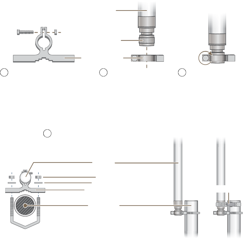
Deployment Guide 43
MOUNTINGTHE HIVEAP 28 AND ATTACHING ANTENNAS
You can mount antennas at the top of a pole as shown in Figure8 and Figure9, or to a flat surface. If you must
mount the antenna lower on a pole, the pole must be nonmetallic—such as one made from a hard plastic like PVC
(polyvinyl chloride)—so that it does not distort the signal. Aerohive recommends that antennas be installed away
from power lines and obstructions that can interfere with radio coverage.
For each antenna that you mount, you need an attachment clamp, a 1 3/8" bolt and nut, a V-bolt, two washers and
two nuts, a hose clamp, and two wrenches.
Figure 8 Securing an Antenna to an Attachment Clamp
1.Insert the 1 3/8" bolt through the attachment clamp and screw a nut loosely onto its end.
2.Place the antenna base cap inside the attachment clamp.
3.Using a pair of wrenches, tighten the nut to the bolt until the clamp grips the base cap firmly.
Figure 9 Mounting an Antenna to a Pole
4.To mount the antenna on a nonmetallic pole, place the attachment clamp against the pole, thread the V-bolt
through the holes on the attachment, the washers, and nuts, and use the wrenches to tighten the nuts to the
bolt. (Optional) For added stability, fasten the top of the antenna to the pole with the hose clamp.
To mount the antenna directly to a flat surface, run bolts or screws (not included) through the two holes in the
attachment clamp, and fasten them firmly to the surface.
߬¬¿½¸³»²¬ Ý´¿³°
Þ¿-» Ý¿°
ß²¬»²²¿
ï íñèŒ
Þ±´¬ Ò«¬
Use one wrench to hold the nut
in place and the other to tighten
the bolt.
Insert the antenna into the clamp
until it grips the base cap.
Insert the bolt through the attachment
clamp and hold it in place with the nut.
Do not tighten it yet.
1 2 3
Ò±²³»¬¿´´·½ б´»
øîŒ ¼·¿³»¬»®÷
ß²¬»²²¿
ر-» Ý´¿³°
Þ·®¼Ž-óÛ§» Ê·»©
ÊóÞ±´¬
Í·¼» Ê·»©
Ò«¬-
É¿-¸»®-
߬¬¿½¸³»²¬ Ý´¿³°
With the attachment clamp against one side of the pole,
insert the V-bolt through the two holes in the clamp from
the other side. Then thread washers and nuts over the two
ends of the bolt and tighten them in place with a wrench.
4
Note: Aerohive recommends attaching the antenna near
the top of the pole. If you need to improve the stability of
the mounted antenna, fasten it to the pole with a hose
clamp (included) as shown on the far right.
or
Chapter 3 The HiveAP 28 Outdoor Platform
44 Aerohive
5.Make sure that all the antenna and cable connectors are clean. If you are using PTFE tape, wrap the tape around
the threads on the HiveAP 28 antenna connectors as explained in "Connecting Antennas Directly to the HiveAP
28" on page42.
6.Assuming that you are using male-to-female cables, connect the female Type N connector on the cables to the
male connectors on the antennas.
7.Connect the male Type N connectors on the cables to the female antenna connectors on the HiveAP 28.
DEVICE, POWER,AND ENVIRONMENTAL SPECIFICATIONS
Understanding the range of specifications for the HiveAP is necessary for optimal deployment and device operation.
The following specifications describe the physical features and hardware components, the power adapter and PoE
(Power over Ethernet) electrical requirements, and the temperature and humidity ranges in which the device can
operate.
Device Specifications
•Chassis dimensions: 13 13/16" W x 4 3/8" H x 8 3/8" D (35 cm W x 11 cm H x 21 cm D)
•Weight: (9 lbs., 4.08 kg)
•Antennas: Two detachable single-band 8dBi 802.11b/g antennas and two detachable single-band 10dBi 802.11a
antennas
•Maximum Transmission Power: 20 dBm
•Ethernet port: autosensing 10/100Base-T/TX Mbps, with IEEE 802.3af-compliant PoE (Power over Ethernet)
Power Specifications
•AC/DC power adapter:
•Input:100 – 240 VAC
•Output: 17 watts
•PoE nominal input voltages: 48 V, 0.35A
•RJ-45 power input pins: Wires 4, 5, 7, 8 or 1, 2, 3, 6
•RF power output:
Environmental Specifications
•Operating temperature: -40 to 140 degrees F (-40 to 60 degrees C)
•Storage temperature: -40 to 194 degrees F (-40 to 90 degrees C)
•Relative Humidity: Maximum 100%
Note: Radio coverage might be limited if the surface acts as an obstruction.
802.11b RF (8-dBi Omnidirectional Antenna, Model S2406BFNM)
Frequency 2412 MHz 2437 MHz 2462 MHz
Peak Power Output (dBm)14.20 14.00 14.20
802.11g RF (8-dBi Omnidirectional Antenna, Model S2406BFNM)
Frequency2412 MHz2437 MHz2462 MHz
Peak Power Output (dBm)16.2016.8015.00
802.11a RF (10-dBi Omnidirectional Antenna, Model S4908WBF)
Frequency 5745 MHz 5785 MHz 5825 MHz
Peak Power Output (dBm)17.80 17.40 17.60
Deployment Guide 45
Chapter 4The HiveAP 340 Platform
The Aerohive HiveAP 340 is a high-performance and highly reliable 802.11n wireless access point. The HiveAP 340
provides dual concurrent 802.11b/g/n and 802.11a/n radios for 3x3 MIMO (Multiple In, Multiple Out) and dual
10/100/1000 Ethernet ports for link aggregation or link redundancy. Its power management system uses a concept
called smart PoE (Power over Ethernet) to adjust its power consumption automatically in response the available
power in different environments. Smart PoE supports the IEEE 802.3af standard and the 802.3at pre-standard.
This chapter covers the following topics relating to the HiveAP:
•"HiveAP 340 Product Overview" on page46
•"Ethernet and Console Ports" on page48
•"Status LEDs" on page52
•"Antennas" on page52
•"Mounting the HiveAP 340" on page56
•"Ceiling Mount" on page56
•"Surface Mount" on page58
•"Device, Power, and Environmental Specifications" on page59
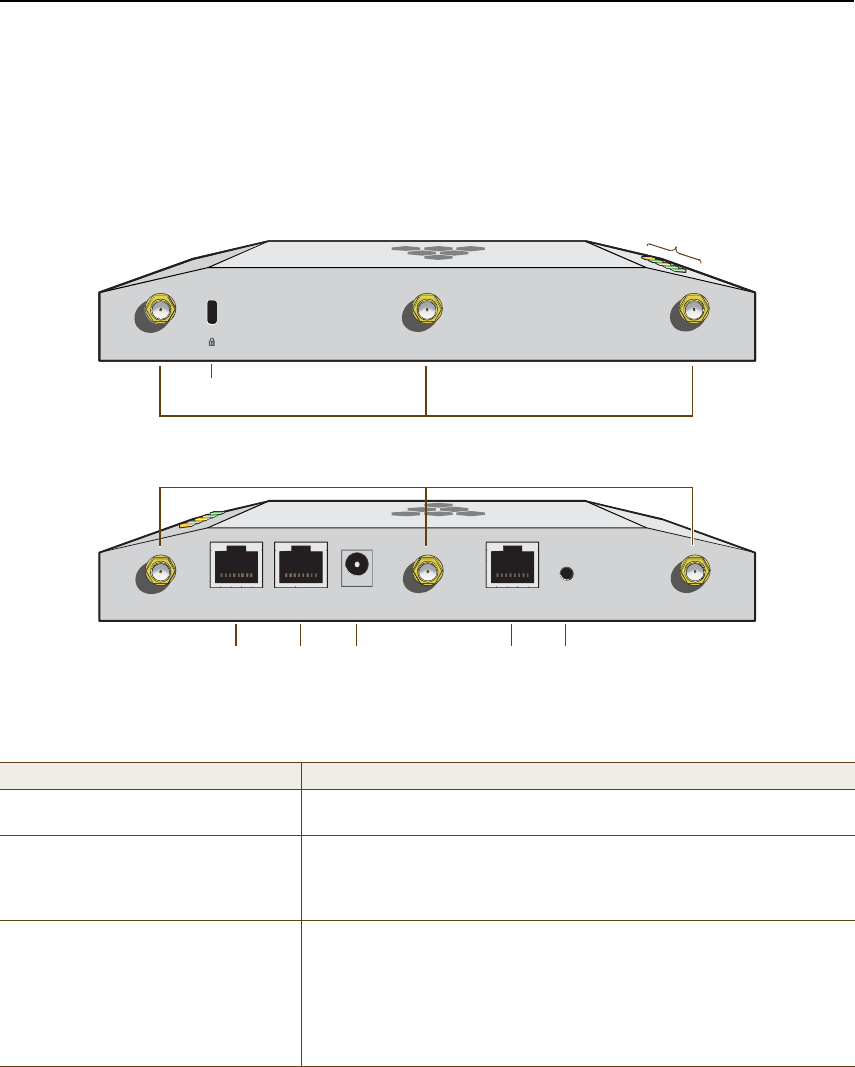
Chapter 4 The HiveAP 340 Platform
46 Aerohive
HIVEAP 340 PRODUCT OVERVIEW
The HiveAP 340 is a multi-channel wireless access point. It is compatible with IEEE 802.11b/g/n (2.4 GHz) and IEEE
802.11a/n (5 GHz) standards and supports a variety of Wi-Fi (wireless fidelity) security protocols, including WPA
(Wi-Fi Protected Access) and WPA2.
You can see the hardware components on the HiveAP in Figure1. Each component is described in Table1.
Figure 1 HiveAP 340 Hardware Components
Table 1 HiveAP 340 Component Descriptions
Component Description
Status LEDsThe status LEDs convey operational states for system power, firmware,
Ethernet interfaces, and radios. For details, see "Status LEDs" on page52.
Device Lock Slot You can physically secure the HiveAP by attaching a lock and cable (such
as a Kensington® notebook lock) to the device lock slot or by using the
lock adapter that is included in the mounting kit and a padlock. For more
information, see "Locking the HiveAP 340" on page57.
802.11a/b/g/n RP-SMA ConnectorsYou can connect up to six detachable single-band antennas to the male
802.11a/b/g/n RP-SMA (reverse polarity-subminiature version A)
connectors. Connect the longer antennas, which support 2.4 GHz
frequencies (for IEEE 802.11b/g/n), to the connectors on the side panel
with the Ethernet ports. Connect the shorter antennas, which support 5
GHz frequencies (for IEEE 802.11a/n), to the connectors on the side panel
with the device lock slot. For details, see "Antennas" on page52.
îòì Ùئ øß÷ îòì Ùئ øÞ÷ îòì Ùئ øÝ÷ÛÌØð ÛÌØï ìèÊ ÜÝ
øòêîëß÷
ÝÑÒÍÑÔÛ ÎÛÍÛÌ
ë Ùئ øß÷ë Ùئ øÞ÷ë Ùئ øÝ÷
Power
Connector
10/100/1000
Mbps PoE Ports
Reset
Button
Console
Port
Device
Lock Slot
Status LEDs
802.11b/g/n RP-SMA Connectors for Detachable Single-Band Antennas
802.11a/n RP-SMA Connectors for Detachable Single-Band Antennas
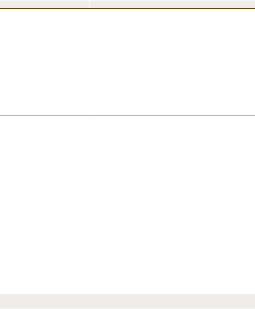
Deployment Guide 47
HIVEAP 340 PRODUCT OVERVIEW
10/100/1000 Mbps PoE Ports The two 10/100/1000-Mbps Ethernet ports—ETH0 and ETH1—support IEEE
802.3af and 802.3at PoE (Power over Ethernet) and receive RJ-45
connectors. The HiveAP can receive power through one or both Ethernet
connections from power sourcing equipment (PSE) that is compatible with
the 802.3af standard and forthcoming 802.at standard. (If you connect
the HiveAP to a power source through the power connector and PoE ports
simultaneously, the device draws power through the power connector and
automatically disables PoE.)
You can configure ETH0 and ETH1 as two individual Ethernet interfaces,
combine them into an aggregate interface to increase throughput, or
combine them into a redundant interface to increase reliability. You can
connect the HiveAP 340 to a wired network or to a wired device (such as
a security camera) through these ports using bridging. They are
compatible with 10/100/1000Base-T/TX and automatically negotiate
half- and full-duplex connections with the connecting device. They are
autosensing and adjust to straight-through and cross-over Ethernet cables
automatically. For details, see "Ethernet and Console Ports" on page48.
Power Connector The 48-volt DC power connector (0.625 amps) is one of two methods
through which you can power the HiveAP 340. To connect it to a 100 –
240-volt AC power source, use the AC/DC power adaptor that is available
as an extra option. Because the HiveAP does not have an on/off switch,
connecting it to a power source automatically powers on the device.
Console Port You can access the CLI by making a serial connection to the RJ-45 console
port. The management station from which you make a serial connection
to the HiveAP must have a VT100 emulation program, such as Tera Term
Pro© (a free terminal emulator) or Hilgraeve Hyperterminal® (provided
with Windows® operating systems). The following are the serial
connection settings: bits per second: 9600, data bits: 8, parity: none,
stop bits: 1, flow control: none. For details, see "Ethernet and Console
Ports" on page48.
Reset Button The reset button allows you to reboot the device or reset the HiveAP to
its factory default settings. Insert a paper clip, or something similar, into
the Reset pinhole and press the reset button. To reboot the device, hold
the button down between 1 and 5 seconds. To return the configuration to
the factory default settings, hold it down for at least 5 seconds. After
releasing the button, the Power LED goes dark as the system reboots.
Then it pulses green while the firmware loads and the system performs a
self-test. After the software finishes loading, the Power LED glows steady
green.
To disable the reset button from resetting the configuration, enter this
command: no reset-button reset-config-enable Pressing the
button between 1 and 5 seconds will still reboot the HiveAP, but pressing
it for more than 5 seconds will not reset its configuration.
Note: The rear surface of the HiveAP 340 is used for heat dissipation to reduce the internal temperature.
Consequently, it can become hot, so use caution when handling it.
Component Description
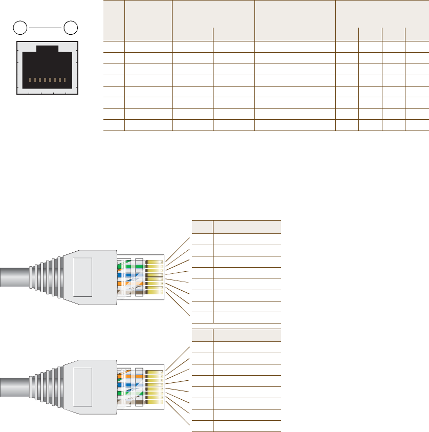
Chapter 4 The HiveAP 340 Platform
48 Aerohive
Ethernet and Console Ports
There are three ports on the HiveAP 340: two RJ-45 10/100/1000Base-T/TX Ethernet ports and an RJ-45 console port.
The pin assignments in the PoE (Power over Ethernet) Ethernet ports follow the TIA/EIA-568-B standard (see
Figure2). The ports accept standard types of Ethernet cable—cat3, cat5, cat5e, or cat6—and can receive power
over this cable from power sourcing equipment (PSE) that is 802.3af-compatible. If you use cat5, cat5e, or cat6
cables, the HiveAP 340 can also support 802.3at-compliant PSE. Such equipment can be embedded in a switch or
router, or it can come from purpose-built devices that inject power into the Ethernet line en route to the HiveAP.
Because the PoE ports have autosensing capabilities, the wiring termination in the Ethernet cable can be either
straight-through or cross-over.
Figure 2 PoE Wire Usage and Pin Assignments
ÛÌØð
Pin T568A Wire Color
1White/Green
2Green
3White/Orange
4Blue
5White/Blue
6Orange
7White/Brown
8Brown
(View of the ETH0 PoE
Port on the HiveAP 340)
8 1
Pin Numbers
Pin T568B Wire Color
1White/Orange
2Orange
3White/Green
4Blue
5White/Blue
6Green
7White/Brown
8Brown
T568A-Terminated Ethernet Cable
with an RJ-45 Connector
802.3af Alternative A
(Data and Power on
the Same Wires)
802.3af Alternative B
(Data and Power on
Separate Wires)
802.3at Wiring Options
Pin Data Signal MDI MDI-X MDI or MDI-X 1 2 3 4
1Transmit +DC+DC–– – –DC1+DC1–DC1+DC1–
2Transmit -DC+DC–– – –DC1+DC1–DC1+DC1–
3Receive +DC–DC+ – – –DC1–DC1+DC1–DC1+
4(unused) – – –– – –DC+ DC2+DC2+DC2–DC2–
5(unused) – – –– – –DC+ DC2+DC2+DC2–DC2–
6Receive -DC– DC+ – – –DC1–DC1+DC1–DC1+
7(unused) – – –– – –DC–DC2–DC2–DC2+DC2+
8(unused) – – –– – –DC–DC2–DC2–DC2+DC2+
MDI = Medium dependent interface for straight-through connections
MDI-X = Medium dependent interface for cross-over (X) connections
The PoE ports are auto-sensing and can automatically adjust to transmit and receive data over straight-through or cross-over Et
herne
connections. Likewise, they can
automatically adjust to 802.3af Alternative A and B power delivery methods. Furthermore, when t
he
Alternative A method is used, the ports automatically allow for polarity reversals depending on their role as either MDI or MDI
-X. In
802.3at, the 1/2 and 3/6 wire pairs connect to DC source 1 and 4/5 and 7/8 pairs to DC source 2 in PSE. Although the exact pola
rity
depends on the PSE design, the HiveAP 340 Ethernet ports can support all possible options.
T568B -terminated Ethernet Cable
with an RJ-45 Connector
T568A and T568B are two standard
wiring termination schemes. Note that
the only difference between them is
that the white/green + solid green pair
of wires and the white/orange + solid
orange pair are reversed.
For straight-through Ethernet
cables—using either the T568A or
T568B standard—the eight wires
terminate at the same pins on each
end.
For cross-over Ethernet cables, the
wires terminate at one end according
to the T568A standard and at the
other according to T568B.
Deployment Guide 49
HIVEAP 340 PRODUCT OVERVIEW
Smart PoE
The HiveAP 340 applies the Aerohive concept of smart PoE to adjust power consumption as necessitated by varying
levels of available power. If the HiveAP needs more power than is available, it first disables the ETH1 interface. If it
still needs more power, it switches from 3x3 MIMO (Multiple In, Multiple Out) to 2x3 (see "MIMO" on page53). In rare
cases when further power conservation is necessary, the HiveAP then reduces the speed on ETH0 from 10/100/1000
Mbps to 10/100 Mbps. Finally, in the event that there is a problem with the PoE switch or Ethernet cable, the HiveAP
disables its wireless interfaces and returns its ETH0 and ETH1 interfaces to 10/100/1000 Mbps speeds. Through the
application of smart PoE, the HiveAP 340 can make power usage adjustments so that it can continue functioning
even when the available power level drops.
Aggregate and Redundant Interfaces
By default ETH0 and ETH1 act as two individual Ethernet interfaces. When both interfaces are connected to the
network and are in backhaul mode, the HiveAP transmits broadcast traffic only through ETH0. The HiveAP transmits
broadcast traffic through ETH1 only when ETH0 does not have network connectivity. When both Ethernet interfaces
are connected to the network and are in access mode, then the HiveAP transmits broadcast traffic through all the
access interfaces: ETH0, ETH1, and all wireless subinterfaces in access mode.
In addition to using ETH0 and ETH1 as individual interfaces, you can combine them into an aggregate interface
(agg0) to increase throughput, or combine them into a redundant interface (red0) to increase reliability. The logical
red0 and agg0 interfaces support all the settings that you can configure for Ethernet interfaces except those
pertaining to physical link characteristics such as link speed. See the sections below for configuration information.
Aggregate Interface
You can increase throughput onto the wired network by combining ETH0 and ETH1 into a single logically aggregated
interface called "agg0". The aggregate interface effectively doubles the bandwidth that each physical interface has
when used individually. In this configuration, both Ethernet ports actively forward traffic, the HiveAP applying an
internal scheduling mechanism based on the source MAC address of each packet to send traffic through the
aggregate member interfaces. To configure an aggregate interface, enter the following commands:
interface eth0 bind agg0
interface eth1 bind agg0
In addition to configuring the HiveAP, you must also configure the connecting switch to support EtherChannel. For
example, the following commands bind two physical Ethernet ports—0/1 and 0/2—to the logical interface
port-channel group 1 on a Cisco Catalyst 2900 switch running Cisco IOS 12.2:
Switch#conf t
Switch(config)#interface port-channel 1
Switch(config-if)#switchport mode access
Switch(config-if)#spanning-tree portfast
Switch(config-if)#exit
Switch(config)#interface fastEthernet 0/1
Switch(config-if)#switchport mode access
Switch(config-if)#channel-group 1 mode on
Switch(config-if)#spanning-tree portfast
Switch(config-if)#exit

Chapter 4 The HiveAP 340 Platform
50 Aerohive
Switch(config)#int fastEthernet 0/2
Switch(config-if)#switchport mode access
Switch(config-if)#channel-group 1 mode on
Switch(config-if)#spanning-tree portfast
Switch(config-if)#exit
Switch(config)#exit
Switch#wr mem
Finally, you must cable the Cisco switch and the HiveAP together: Cisco 0/1 to HiveAP eth0, and Cisco 0/2 to HiveAP
eth1.
Redundant Interface
If a single Ethernet link provides sufficient bandwidth and speed, such as a 1000 Mbps link, but you want to ensure
link redundancy, you can connect the two Ethernet ports to the same switch—or to two different switches—and
configure them to act as a redundant interface called "red0". In this mode, only one Ethernet interface is actively
forwarding traffic at any one time. If eth0 is active and eth1 is passive and eth0 loses its connection, the HiveAP
switches over to eth1. To configure a redundant interface, enter the following commands:
interface eth0 bind red0 primary
interface eth1 bind red0
The interface that you specify as primary is the one that the HiveAP uses when both interfaces have network
connectivity. Because the HiveAP uses eth0 as the primary interface by default, it is unnecessary to specify
"primary" in the first command above. However, it is included to make the role of eth0 as the primary interface
obvious.
Interface Selection for the Default Route
In cases where there are multiple active interfaces in backhaul mode, the HiveAP uses the following logic to choose
which interface to use in its default route:
•If there is an Ethernet interface and a wireless interface in backhaul mode, the HiveAP uses the Ethernet
interface in its default route.
•If there are multiple Ethernet interfaces in backhaul mode, the HiveAP chooses which one to use in its default
route in the following order:
•It uses red0 or agg0 if one of them has at least one member interface bound to it and its link state is UP.
•It uses ETH0 if neither red0 nor agg0 has any member interfaces and the link state for ETH0 is UP.
•It uses ETH1 if neither red0 nor agg0 has any member interfaces, the link state for ETH0 is DOWN, and the
link state for ETH1 is UP.
Note: No extra configuration is necessary on the connecting switch or switches to support a redundant interface.
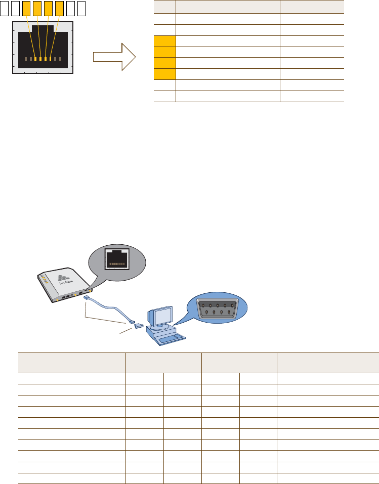
Deployment Guide 51
HIVEAP 340 PRODUCT OVERVIEW
Console Port
The pin-to-signal mapping in the RJ-45 console port is shown shown in Figure3.
Figure 3 Console Port Pin Assignments
To make a serial connection between your management system and the HiveAP, you can use the console cable that
is available as an extra option. Insert the RJ-45 connector into the HiveAP 340 console port, and attach the DB-9
connector to the serial (or COM) port on your management system. The management system must have a VT100
terminal emulation program, such as Tera Term Pro© (a free terminal emulator) or Hilgraeve Hyperterminal®
(provided with Windows® operating systems). If you want to make your own serial cable and adapter, refer to
Figure3.
Figure 4 Wiring Details for Making a Serial Cable with an RJ-45-to-Female DB-9 Adapter
ÝÑÒÍÑÔÛ
Pin Signal Direction
1RTS (Request to Send)Output, unused
2DTR (Data Terminal Ready)Output, unused
3TXD (Transmitted Data)Output
4Ground Ground
5Ground Ground
6RXD (Received Data)Input
7DSR (Data Set Ready)Input, unused
8CTS (Clear to Send) Input, unused
RJ-45 Console Port
(View of the console
port on the HiveAP)
Because this is a console port, only pins 3,4,5, and 6 are currently in use.
Console Port Pin Assignments
613457 28
α´´±ª»® Ý¿¾´» ©·¬¸
ÎÖóìë ݱ²²»½¬±®-
ÎÖóìëó¬±óÚ»³¿´» ÜÞóç ß¼¿°¬»®
ݱ²-±´» ᮬ
ÝÑÓ Ð±®¬
ø±² Þ¿½µ п²»´÷
ÝÑÒÍÑÔÛ
Ó¿²¿¹»³»²¬ ͧ-¬»³
Ø·ª»ßÐ íìð
Console Port
(HiveAP 340)
RJ-45-to-RJ-45
Rollover Cable
RJ-45-to-Female
DB-9 Adapter
Management
System
SignalRJ-45 PinRJ-45 PinRJ-45 PinDB-9 PinSignal
RTS (Request to Send)1818CTS (unused)
DTR (Data Terminal Ready)2726DSR (unused)
TXD (Transmitted Data)3632RXD
Ground4545Ground
Ground5455Ground
RXD (Received Data)6363TXD
DSR (Data Set Ready)7274DTR (unused)
CTS (Clear to Send)8187RTS (unused)
----9RI (Ring Indicator, unused)
Chapter 4 The HiveAP 340 Platform
52 Aerohive
Status LEDs
The five status LEDs on the top of the HiveAP 340 indicate various states of activity through their color (dark, green,
amber, and red) and illumination patterns (steady glow or pulsing). The meanings of the various color + illumination
patterns for each LED are explained below.
Power
•Dark: No power
•Steady green: Powered on and the firmware is running normally
•Pulsing green: Firmware is booting up
•Steady amber: Alarm indicating a firmware issue has occurred
•Pulsing amber: Firmware is being updated
•Steady red: Alarm indicating a hardware issue has occurred
ETH0 and ETH1
•Dark: Ethernet link is down or disabled
•Steady green: 1000 Mbps Ethernet link is up but inactive
•Pulsing green: 1000 Mbps Ethernet link is up and active
•Steady amber: 10/100 Mbps Ethernet link is up but inactive
•Pulsing amber: 10/100 Mbps Ethernet link is up and active
WIFI0 and WIFI1
•Dark: Wireless interface is disabled
•Steady green: Wireless interface is in access mode but inactive
•Pulsing green: Wireless interface is in access mode and active
•Steady amber: Wireless interface is in backhaul mode but inactive
•Pulsing amber: Wireless interface is in backhaul mode and active
•Alternating green and amber: Wireless interface is in backhaul mode and is searching for other hive
members
Antennas
The HiveAP 340 can accept up to six detachable dipole antennas. The three shorter antennas are designed for the 5
GHz band and have a 2-dBi gain. The three longer antennas are designed for the 2.4 GHz band and have a 4.9-dBi
gain. These antennas are omnidirectional, providing fairly equal coverage in all directions in a toroidal
(donut-shaped) pattern around each antenna (see Figure4 on page28). For greater coverage on a horizontal plane,
it is best to orient the antennas vertically. So that you can easily do that whether the HiveAP chassis is mounted
horizontally or vertically, the antennas hinge and swivel (see Figure5 on page53.)
Although hive members automatically adjust their signal strength according to their environments, you can resize
the area of coverage by increasing or decreasing the signal strength manually by entering the interface {
wifi0 | wifi1 } radio power <number> command, where <number> can be from 1 to 20 and represents
a value in dBm.
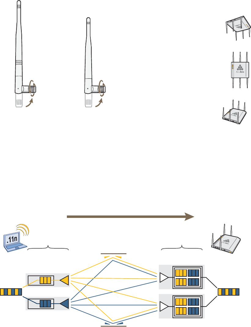
Deployment Guide 53
HIVEAP 340 PRODUCT OVERVIEW
Figure 5 HiveAP 340 Antennas
MIMO
MIMO (Multiple In, Multiple Out) is a major WLAN advancement introduced in the IEEE 802.11n standard in which
multiple RF links are formed on the same channel between the transmitter and receiver simultaneously. To
accomplish this, the transmitter separates a single data stream into multiple spatial streams, one for each RF chain
(an antenna + various digital signal processing modules linked to the antenna). The transmit antennas at the end of
each RF chain then transmit their spatial streams. The recipient’s receive antennas obtain streams from all the
transmit antennas. In fact, due to multipath, they receive multiple streams from each transmit antenna. The
receive antennas pass the spatial streams to the digital signal processors in their RF chains, which take the best data
from all the spatial streams and reassemble them into a single data stream once again (see Figure6).
Figure 6 2x2 MIMO (2 Transmit Antennas x 2 Receive Antennas)
ë Ùئ ß²¬»²²¿ º±® ×ÛÛÛ
èðîòïï¿ñ²
Ô»²¹¬¸ ©¸»² º«´´§
»¨¬»²¼»¼æ ë ïëñïêŒ øïë ½³÷
îòì Ùئ ß²¬»²²¿ º±®
×ÛÛÛ èðîòïï¾ñ¹ñ²
Ô»²¹¬¸ ©¸»² º«´´§
»¨¬»²¼»¼æ é éñèŒ øîð ½³÷
The base of the antennas hinge up to 90 degrees so that you
can orient the antennas independently of the orientation of
the HiveAP chassis. The antennas also rotate in a full circle.
When mounting the HiveAP
340 on a ceiling, orient its
antennas downward.
When mounting the HiveAP
on a wall or post, fully extend
its antennas upward and
downward.
When mounting the HiveAP
above a ceiling or on a
horizontal beam, orient its
antennas upward.
Generally, orient the antennas vertically for
improved radio coverage, as shown here:
Ì®¿²-³·¬
ß²¬»²²¿-
Ü·¹·¬¿´ Í·¹²¿´
Ю±½»--±®-
ÎÚ Ý¸¿·²- ÎÚ Í·¹²¿´- øÓ«´¬·°¿¬¸÷
λ½»·ª»
ß²¬»²²¿-
Ü·¹·¬¿´ Í·¹²¿´
Ю±½»--±®-
ÎÚ Ý¸¿·²-
èðîòïï² ©·®»´»-- ½´·»²¬
©·¬¸ ¬©± ¿²¬»²²¿-
Ø·ª»ßÐ íìð «-·²¹
¬©± ¿²¬»²²¿-
Ѿ¶»½¬
Ü¿¬¿
λ¿--»³¾´»¼
Ü¿¬¿
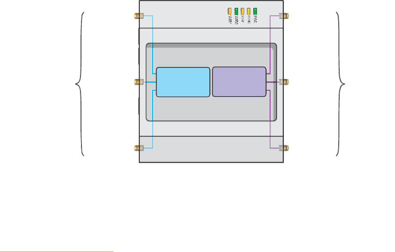
Chapter 4 The HiveAP 340 Platform
54 Aerohive
In previous 802.11 standards, access points and clients each employed a single set of components, or RF chain, for
transmitting or receiving. Although two antennas are often used for diversity, only the one with the best
signal-to-noise ratio is used at any given moment, and that antenna makes use of the single RF chain while the other
antenna remains inactive. A significant improvement that MIMO introduces is to permit each antenna to have its
own RF chain and for all antennas to function simultaneously. For the HiveAP340, you can connect up to three
antennas per radio and configure the radio to use two or three transmit chains and two or three receive chains.1
Using two or three transmit and receive chains simultaneously increases the amount of data that can flow across the
WLAN and accelerates the processing of that data at each end of the wireless link.
Another major aspect of MIMO is how it turns multipath signals from a curse to a boon. As a radio signal moves
through space, some objects reflect it, others interfere with it, and still others absorb it. The receiver can end up
receiving multiple copies of the original signal, all kind of muddled together. However, the digital signal processors
in the multiple receive chains are able to combine their processing efforts to sort through all the received data and
reconstruct the original message. Furthermore, because the transmitter makes use of multiple RF chains, there is
an even richer supply of signals for the receive chains to use in their processing. To set the transmit and receive RF
chains for a radio profile, enter the following commands:
radio profile <name> transmit-chain { 2 | 3 }
radio profile <name> receive-chain { 2 | 3 }
There are two sets of antennas—three antennas per set—that operate concurrently in two different frequency
ranges: 2.4GHz (IEEE 802.11b/g/n) and 5 GHz (IEEE 802.11a/n). Using two different frequency ranges reduces the
probability of interference that can occur when numerous channels operate within the same range. Conceptually,
the relationship of antennas and radios is shown in Figure7.
Figure 7 Antennas and Radios
\
The wifi0 interface links to radio 1 (frequency range = 2.4 GHz for IEEE 802.11b/g), and the wifi1 interface links to
radio2 (frequency range = 5 GHz for IEEE 802.11a). These interface-to-radio relationships are permanent.
When deciding how many antennas to use, consider the types of wireless clients—802.11n only, 802.11g/n,
802.11b/g/n, or 802.11a/n—the area needing coverage, and the RF environment.
1.The convention for presenting the configuration of transmitting and receiving MIMO RF chains is TxR. For
example, a HiveAP 340 radio functioning in access mode might be configured to use two RF chains for
transmitting and three for receiving. In that case, its configuration can be presented as "2x3". In general, the
number of receive antennas is equal to or greater than the number of transmit antennas.
ο¼·± ï
ÎÚ èðîòïï¾ñ¹ñ²
îòì Ùئ
ο¼·± î
ÎÚ èðîòïï¿ñ²
ë Ùئ
îòì Ùئ øß÷
îòì Ùئ øÞ÷
îòì Ùئ øÝ÷
ë Ùئ øß÷
ë Ùئ øÞ÷
ë Ùئ øÝ÷
ÎÐóÍÓß
ݱ²²»½¬±®-
ÎÐóÍÓß
ݱ²²»½¬±®-
Cut-away view of the HiveAP 340 to show the relationship of the antennas and the two internal radios
Deployment Guide 55
HIVEAP 340 PRODUCT OVERVIEW
Using MIMO with Legacy Clients
In addition to supporting up to 300-Mbps throughput per radio for 802.11n clients, MIMO (Multiple In, Multiple Out)
can improve the reliability and speed of legacy 802.11a/b/g client traffic. When an 802.11a/b/g access point does
not receive acknowledgement that a frame it sent was received, it resends that frame, possibly at a somewhat
lower transmission rate. If the access point must continue resending frames, it will continue lowering its
transmission rate. As a result, clients that could get 54-Mbps throughput in an interference-free environment might
have to drop to 48- or 36-Mbps speeds due to multipath interface. However, because MIMO technology makes better
use of multipath, an access point using MIMO can continue transmitting at 54 Mbps, or at least at a better rate than
it would in a pure 802.11a/b/g environment, thus improving the reliability and speed of 802.11a/b/g client traffic.
Although 802.11a/b/g client traffic can benefit somewhat from an 802.11n access point using MIMO, supporting such
legacy clients along with 802.11n clients can have a negative impact on 802.11n client traffic. Legacy clients take
longer to send the same amount of data as 802.11n clients. Consequently, legacy clients consume more airtime than
802.11n clients do, causing greater congestion in the WLAN and reducing 802.11n performance.
By default, the HiveAP 340 supports 802.11a/b/g clients. You can restrict access only to clients using the IEEE
802.11n standard. By only allowing traffic from clients using 802.11n, you can increase the overall bandwidth
capacity of the access point so that there will not be an impact on 802.11n clients during times of network
congestion. To do that, enter the following command:
radio profile <string> 11n-clients-only
You can also deny access just to clients using the IEEE 802.11b standard, which has the slowest data rates of the
three legacy standards, while continuing to support 802.11a and 802.11g clients. To do that, enter the following
command:
no radio profile <string> allow-11b-clients
By blocking access to 802.11b clients, their slower data rates cannot clog the WLAN when the amount of wireless
traffic increases.
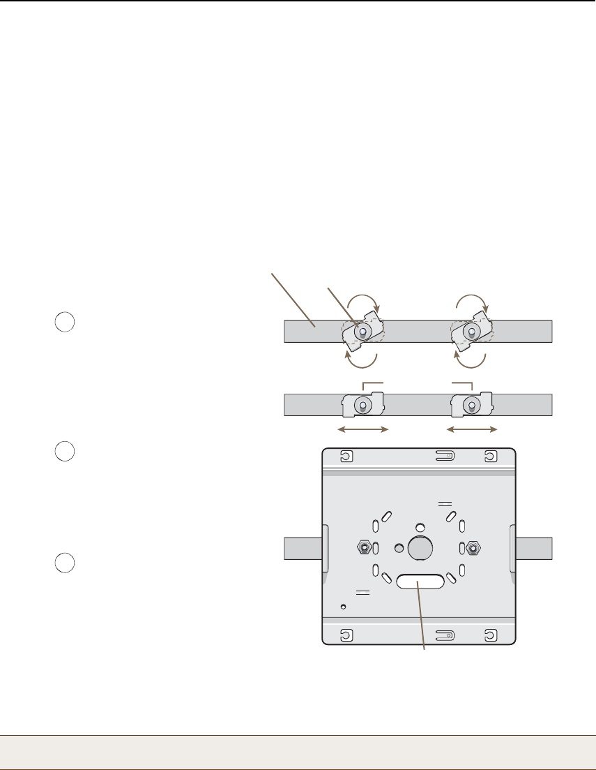
Chapter 4 The HiveAP 340 Platform
56 Aerohive
MOUNTINGTHE HIVEAP 340
Using the mounting plate and track clips, you can mount the HiveAP 340 to the tracks of a dropped ceiling grid.
Using just the mounting plate, you can mount the HiveAP to any surface that can support its weight (3.3 lb., 1.5 kg).
Ceiling Mount
To mount the HiveAP 340 to a track in a dropped ceiling, you need the mounting plate, two track clips, and two Keps
nuts that ship as an option with the HiveAP 340. You also need a wrench and—most likely—a ladder.
Nudge the ceiling tiles slightly away from the track to clear some space. Attach the track clips to the ceiling track,
and then fasten the mounting plate to the clips, as shown in Figure8. When you have the mounting plate in the
correct location, cut or drill a hole in the ceiling through which you can then pass the Ethernet and power cables.
Figure 8 Attaching the Track Clips and Mounting Plate to the Ceiling Track
Attach the HiveAP 340 to the mounting plate and connect the cables, as shown in Figure9 on page57.
Note: You can tie the cables to the tie points (small arched strips) on the mounting plate to prevent them from
being pulled out of their connections accidentally.
ï
î
Ю»-- ¬¸» ¬®¿½µ ½´·°- ¿¹¿·²-¬ ¬¸»
½»·´·²¹ ¬®¿½µ ¿²¼ -©·ª»´ ¬¸»³ «²¬·´
¬¸»§ ¹®·° ¬¸» »¼¹»- ±º ¬¸» ¬®¿½µò
׺ ²»½»--¿®§ô -´·¼» ±²» ±® ¾±¬¸ ±º
¬¸» ½´·°- ¿´±²¹ ¬¸» ¬®¿½µ ¬± °±-·¬·±²
¬¸»³ ¿¬ ¬¸» °®±°»® ¼·-¬¿²½» ¬± º·¬
¬¸®±«¹¸ ¬¸» ¸±´»- ·² ¬¸» ³±«²¬·²¹
°´¿¬» øî ïñìŒ ±® é ½³÷ò
ײ-»®¬ ¬¸» ³±«²¬·²¹ °´¿¬» ±ª»® ¬¸»
¾±´¬- ¿¬¬¿½¸»¼ ¬± ¬¸» ¬®¿½µ ½´·°-ô
¿²¼ «-» ¬¸» Õ»°- ²«¬- ¬± º¿-¬»²
¬¸» °´¿¬» ¬± ¬¸» ½´·°-ò
Ë-» ¿ ©®»²½¸ ¬± ¬·¹¸¬»² ¬¸» ²«¬-
º·®³´§ ¬± ¬¸» ¾±´¬- ¿²¼ -»½«®» ¬¸»
°´¿¬» ¬± ¬¸» ¬®¿½µò
í̸®±«¹¸ ¬¸» ±¾´±²¹ ±°»²·²¹ ·² ¬¸»
°´¿¬»ô ½«¬ ±® ¼®·´´ ¿ ¸±´» ·² ¬¸» ½»·´·²¹
¬·´» ø²±¬ -¸±©²÷ò ̸»² °¿-- ±²» ±®
¾±¬¸ Û¬¸»®²»¬ ½¿¾´»- ¬¸®±«¹¸ ¬¸»
¸±´»ô ¿²¼ ·º §±« °´¿² ¬± -«°°´§ °±©»®
º®±³ ¿² ßÝ °±©»® -±«®½» ®¿¬¸»® ¬¸¿²
¬¸®±«¹¸ бÛô °¿-- ¬¸» °±©»® ½¿¾´»
¬¸®±«¹¸ ¿- ©»´´ò
Ý«¬ ¸±´» ·² ½»·´·²¹ ¬·´» ¿²¼
º»»¼ ½¿¾´»- ¬¸®±«¹¸ ¸»®»ò
Ó±«²¬·²¹ д¿¬»
Ý»·´·²¹ Ì®¿½µ
Ì®¿½µ Ý´·°
ø©±®³-Ž- »§» ª·»© ©·¬¸ ½»·´·²¹
¬·´»- ®»³±ª»¼ º±® ½´¿®·¬§÷
î ïñì • øé ½³÷
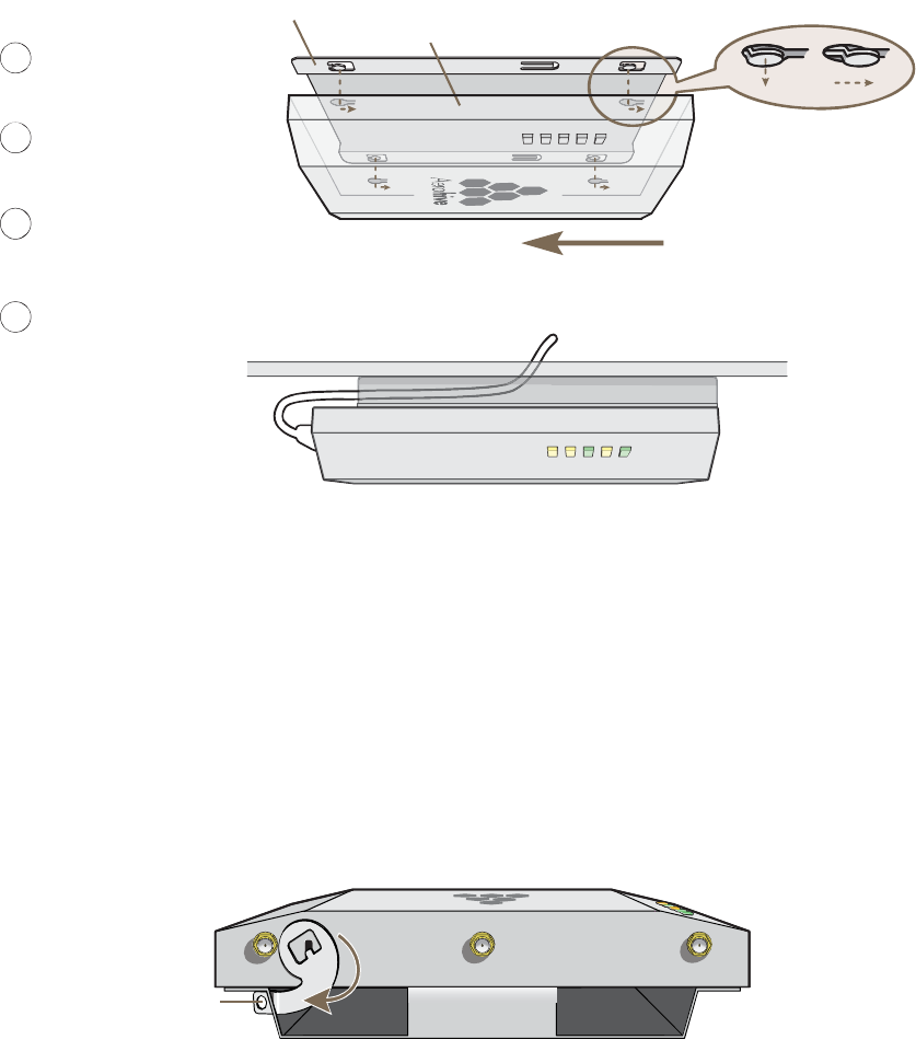
Deployment Guide 57
MOUNTINGTHE HIVEAP 340
Figure 9 Attaching the HiveAP 340 to the Mounting Plate and Connecting Cables
When done, adjust the ceiling tiles back into their former position.
Locking the HiveAP 340
To lock the HiveAP 340 to the mounting plate, use either a Kensington lock or the lock adapter that is included with
the mounting kit and a small padlock (not included).
To use a Kensington lock, loop the cable attached to the lock around a secure object, insert the T-bar component of
the lock into the device lock slot on the HiveAP, and then turn the key to engage the lock mechanism.
To use the lock adapter :
1.Insert the T-shaped extension on the adapter into the device lock slot, and rotate it clockwise so that the
curved section extends through the slot in the mounting plate (see Figure10).
Figure 10 Locking the HiveAP 340 to the Mounting Plate
2.Link a padlock through the opening in the adapter and engage the lock to secure the HiveAP 340 to the
mounting plate. The opening is 1/8" (0.3 cm) in diameter at its narrowest.
É·¬¸ ¬¸» Ø·ª»ßÐ íìð «°-·¼»
¼±©²ô ¿´·¹² ·¬- °±®¬ -·¼» ©·¬¸
¬¸» »¼¹» ±º ¬¸» °´¿¬»ò
Ы-¸ ¬¸» Ø·ª»ßÐ íìð «°©¿®¼ô
·²-»®¬·²¹ ¬¸» º±«® ¬¿¾- ±² ¬¸»
°´¿¬» ·²¬± ¬¸» º±«® -´±¬- ±² ¬¸»
Ø·ª»ßÐ íìðò
Í´·¼» ¬¸» Ø·ª»ßÐ íì𠬱©¿®¼
¬¸» °±®¬ °¿²»´ô ´±½µ·²¹ ¬¸» ¬¿¾-
·²-·¼» ¬¸» -´±¬-ò
ݱ²²»½¬ ¬¸» ½¿¾´»- ¬±
½±³°´»¬» ¬¸» ·²-¬¿´´¿¬·±²ò
ì
ê
é
ëÌ¿¾
·²-·¼»
-´±¬ò
Ì¿¾
´±½µ»¼ ·²
°´¿½»ò
Ó±«²¬·²¹ д¿¬»
Ø·ª»ßÐ íìð ø-¸±©² ¿- ¬®¿²-°¿®»²¬ º±® ½´¿·®¬§÷
Ì¿¾
Í´±¬
ø-·¼» ª·»©÷
Ó±«²¬·²¹ д¿¬»
Ø·ª»ßÐ íìð
Ý»·´·²¹
Ý¿¾´»- °¿-- ¬¸®±«¹¸ ¬¸» ¸±´» ·²
¬¸» ³±«²¬·²¹ °´¿¬» ¿²¼ ½»·´·²¹
ë Ùئ øß÷ë Ùئ øÞ÷ë Ùئ øÝ÷
ન¬» ¬¸»
´±½µ ¿¼¿°¬»®
½´±½µ©·-»ò
ײ-»®¬ ¿ ´±½µ
¬¸®±«¹¸ ¬¸»
±°»²·²¹ò
HiveAP 340
Mounting Plate
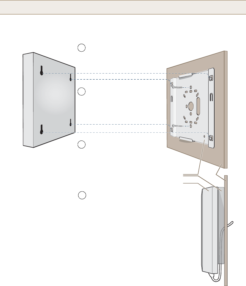
Chapter 4 The HiveAP 340 Platform
58 Aerohive
Surface Mount
You can use the mounting plate to attach the HiveAP 340 to any surface that supports its weight, and to which you
can screw or nail the plate. First, mount the plate to the surface. Then, through one of the two large openings in
the plate, make a hole in the wall so that you can pass the cables through to the HiveAP.
Finally, attach the device to the plate, and connect the cables, as shown in Figure11.
Figure 11 Mounting the HiveAP on a Wall
Note: You can tie the cables to the tie points on the mounting plate to prevent them from being pulled out of
their connections accidentally.
Ó±«²¬·²¹ д¿¬»
Ø·ª»ßÐ íìð
É¿´´
Insert the tabs on the mounting plate
into the slots on the underside of the
HiveAP 340. Then push the HiveAP
340 downward to lock it in place.
With the two wings at the sides of the plate
extending away from the surface, attach the
mounting plate to a secure object such as a
wall, ceiling, post, or beam.
1
3
Note: There are a variety of holes through which you can
screw or nail the plate in place. Choose the two or three
that best suit the object to which you are attaching it.
HiveAP 340
2Cut or drill a hole through one of the
openings in the mounting plate to
pass the cables through to the
HiveAP 340.
Connect the cables to the HiveAP 340.
Depending on the deployment, you might
connect one or two Ethernet cables and a
power cable.
4
(side view)

Deployment Guide 59
DEVICE, POWER,AND ENVIRONMENTAL SPECIFICATIONS
DEVICE, POWER,AND ENVIRONMENTAL SPECIFICATIONS
Understanding the range of specifications for the HiveAP 340 is necessary for optimal deployment and device
operation. The following specifications describe the physical features and hardware components, the power adapter
and PoE (Power over Ethernet) electrical requirements, and the temperature and humidity ranges in which the
device can operate.
Device Specifications
•Chassis dimensions: 8 3/8" W x 1 1/8" H x 8" D (21.3 cm W x 3 cm H x 20.3 cm D)
•Weight: 3 lb. (1.36 kg)
•Antennas: Three omnidirectional 802.11b/g/n antennas, and three omnidirectional 802.11a/n antennas
•Serial port: DB-9 (bits per second: 9600, data bits: 8, parity: none, stop bits: 1, flow control: none)
•Ethernet port: autosensing 10/100Base-T/TX Mbps, with IEEE 802.3af-compliant PoE (Power over Ethernet)
Power Specifications
•AC/DC power adapter:
•Input:100 – 240 VAC
•Output: 48V/0.38A
•PoE nominal voltages:
•Input: 48 V/0.35A
•Output: 48 V/0.625A
•RJ-45 power input pins: Wires 4, 5, 7, 8 or 1, 2, 3, 6
Environmental Specifications
•Operating temperature: -4 to 131 degrees F (-20 to 55 degrees C)
•Storage temperature: -40 to 176 degrees F (-40 to 80 degrees C)
•Relative Humidity: Maximum 95%
Chapter 4 The HiveAP 340 Platform
60 Aerohive
Deployment Guide 61
Chapter 5The HiveManager Platform
The HiveManager Network Management System provides centralized configuration, monitoring, and reporting for
multiple HiveAPs. The following are a few of the many benefits that a HiveManager offers:
•Simplified installations and management of up to 500 HiveAPs
•Profile-based configurations that simplify the deployment of large numbers of HiveAPs
•Scheduled firmware upgrades on HiveAPs by location
•Exportation of detailed information on HiveAPs for reporting
This chapter covers the following topics related to the HiveManager platform:
•"Product Overview" on page62
•"Ethernet and Console Ports" on page63
•"Status LEDs" on page64
•"Rack Mounting the HiveManager" on page65
•"Device, Power, and Environmental Specifications" on page66
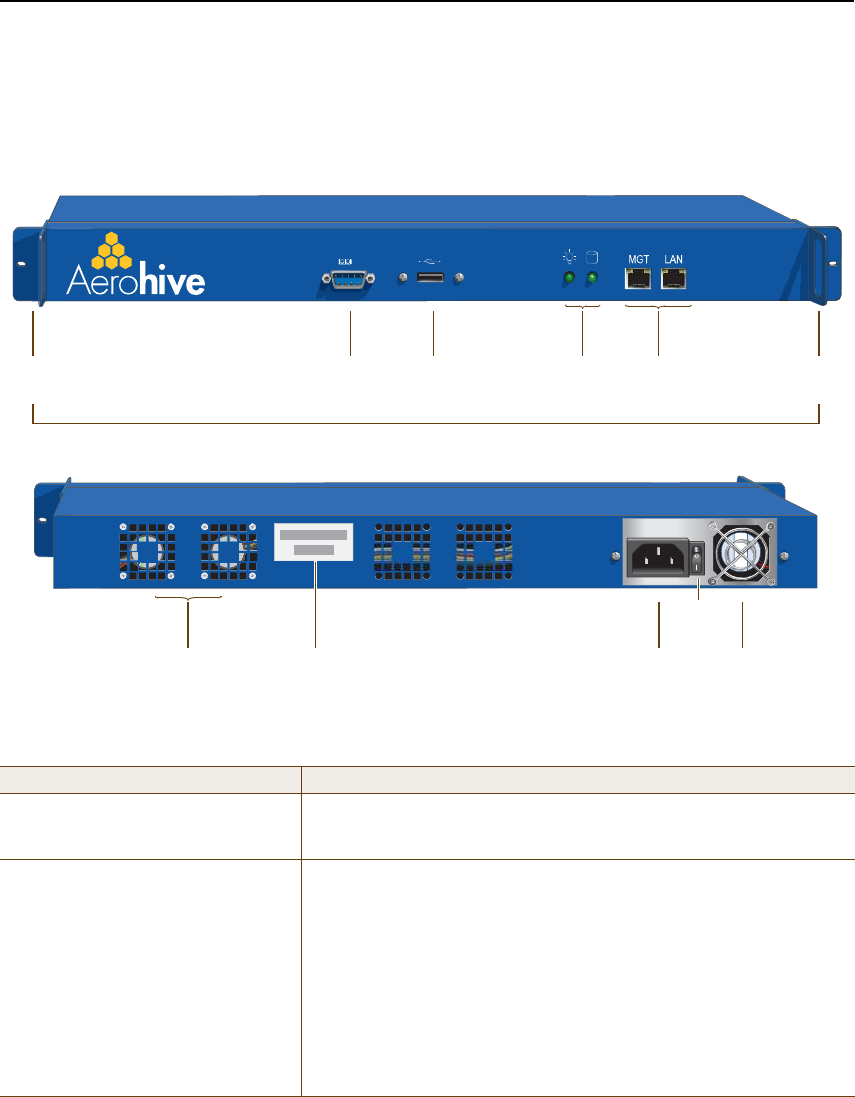
Chapter 5 The HiveManager Platform
62 Aerohive
PRODUCT OVERVIEW
The Aerohive HiveManager is a central management system for configuring and monitoring HiveAPs. You can see its
hardware components in Figure1 and read a description of each component in Table1.
Figure 1 HiveManager Hardware Components
Table 1 HiveManager Component Descriptions
Component Description
Mounting BracketsThe two mounting brackets allow you to mount the HiveManager in a
standard 19" (48.26 cm) equipment rack. You can also move the brackets
to the rear of the chassis if you need to reverse mount it.
Console PortA male DB-9 serial port to which you can make a console connection using
an RS-232 (or "null modem") cable. The pin assignments are the same as
those on the HiveAP (see "Ethernet and Console Ports" on page26).
The management station from which you make a serial connection to the
HiveManager must have a VT100 emulation program, such as Tera Term
Pro© (a free terminal emulator) or Hilgraeve Hyperterminal® (provided
with Windows® operating systems). The following are the serial
connection settings: bits per second: 9600, data bits: 8, parity: none,
stop bits: 1, flow control: none. The default login name is admin and the
password is aerohive. After making a connection, you can access the
Linux operating system.
USB
Port
Console
Port
Status
LEDs
Mounting
Bracket
MGT and LAN
Ethernet Ports
Mounting
Bracket
Power
Fan
System
Fans
AC Power
Inlet
Serial Number
Label
On/Off
Switch
Front Panel
Rear Panel
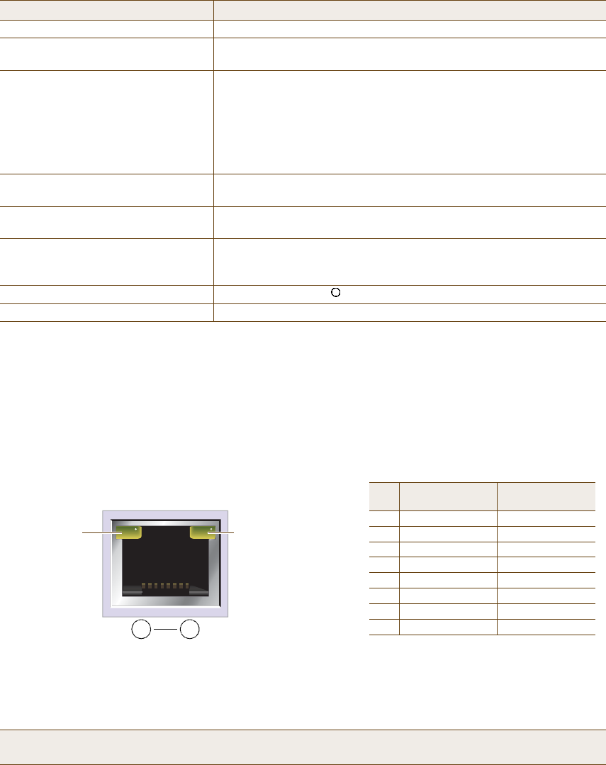
Deployment Guide 63
PRODUCT OVERVIEW
Ethernet and Console Ports
The two 10/100/1000-Mbps Ethernet ports on the HiveManager labeled MGT and LAN use standard RJ-45 connector
pin assignments that follow the TIA/EIA-568-B standard (see Figure2). They accept standard types of Ethernet
cable—cat3, cat5, cat5e, or cat6. Because the ports have autosensing capabilities, the wiring termination in the
Ethernet cables can be either straight-through or cross-over.
Figure 2 Ethernet Port LEDs and Pin Assignments
USB Port The USB port is reserved for internal use.
Status LEDs The status LEDs convey operational states for the system power and hard
disk drive. For details, see "Status LEDs" on page64.
MGT and LAN Ethernet Ports The MGT and LAN Ethernet ports are compatible with 10/100/1000-Mbps
connections, automatically negotiate half- and full-duplex mode with the
connecting devices, and support RJ-45 connectors. They are autosensing
and automatically adjust to straight-through and cross-over Ethernet
cables. The two ports allow you to separate traffic between the
HiveManager and its administrators from traffic between the
HiveManager and the HiveAPs it manages.
System Fans The two system fans maintain an optimum operating temperature. Be
sure that air flow through the system fan vents is not obstructed.
Serial Number Label The serial number label contains the FCC compliance stamp, model
number, input power specifications, and serial number for the device.
AC Power Inlet The three-prong AC power inlet is a C14 chassis plug through which you
can connect a HiveManager to a 100 – 240-volt AC power source using the
10-amp/125-volt IEC power cord that ships with the product.
On/Off Switch The on ( | ) and off ( ) switch controls the power to the HiveManager.
Power Fan The fan that maintains the temperature of the power supply.
Note: The default IP address/netmask for the MGT interface is 192.168.2.10/24. For the LAN interface, the
default IP address/netmask is 192.168.3.10/24. The IP address of the default gateway is 192.168.2.1.
Component Description
(View of an Ethernet port
on the HiveManager)
8 1
Pin Numbers
Pin
10/100Base-T
Data Signal
1000Base-T
Data Signal
1Transmit +BI_DA+
2Transmit - BI_DA-
3Receive + BI_DB+
4(unused) BI_DC+
5(unused) BI_DC-
6Receive - BI_DB-
7(unused) BI_DD+
8(unused) BI_DD-
Legend: BI_D = bidirectional
A+/A-, B+/B-, C+/C-, D+/D- = wire pairings
The Ethernet ports are auto-sensing and can automatically adjust to transmit and receive data over straight-through or cross-ov
er
Ethernet connections. For a diagram showing T568A and T568B wiring, see "Ethernet and Console Ports" on page26.
Link Rate LED
Dark: 10 Mbps
Green: 100 Mbps
Amber: 1000 Mbps
Link Activity LED
Dark: Link is down
Steady amber: Link is up
but inactive
Blinking amber: Link is up
and active
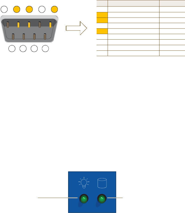
Chapter 5 The HiveManager Platform
64 Aerohive
The pin assignments in the male DB-9 console port follow the EIA (Electronic Industries Alliance) RS-232 standard. To
make a serial connection between your management system and the console port on the HiveManager, you can use a
null modem serial cable, use another serial cable that complies with the RS-232 standard, or refer to the
pin-to-signal mapping shown in Figure3 to make your own serial cable. Connect one end of the cable to the console
port on the HiveManager and the other end to the serial (or COM) port on your management system. The
management system must have a VT100 terminal emulation program, such as Tera Term Pro© (a free terminal
emulator) or Hilgraeve Hyperterminal® (provided with Windows® operating systems).
Figure 3 Console Port Pin Assignments
The serial connection settings are as follows:
•Bits per second: 9600
•Data bits: 8
•Parity: none
•Stop bits: 1
•Flow control: none
Status LEDs
The two status LEDs on the front of the HiveManager indicate various states of activity through their color (dark,
green, amber) and illumination patterns (steady glow or blinking). The meanings of the various color + illumination
patterns for each LED are shown in Figure4.
Figure 4 Status LEDs
12345
6789
Pin Signal Direction
1DCD (Data Carrier Detect)(unused)
2RXD (Received Data)Input
3TXD (Transmitted Data)Output
4DTR (Data Terminal Ready)(unused)
5Ground Ground
6DSR (Data Set Ready)(unused)
7RTS (Request to Send)(unused)
8CTS (Clear to Send) (unused)
9RI (Ring Indicator) (unused)
Male DB-9 Console Port
(View of the console port
on the HiveManager)
The above pin assignments show a DTE configuration for a
DB-9 connector complying with the RS-232 standard. Because
this is a console port, only pins 2,3, and 5 need be used.
RS-232 Standard Pin Assignments
System Power
Dark: No power
Steady illumination: Powered on
Hard Disk Drive
Dark: Idle
Blinking: Active
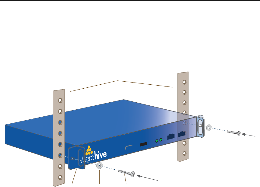
Deployment Guide 65
RACK MOUNTINGTHE HIVEMANAGER
RACK MOUNTINGTHE HIVEMANAGER
You can mount the HiveManager in a standard 19" (48 cm) equipment rack with two rack screws—typically 3/4",
1/2", or 3/8" long with 10-32 threads. The HiveManager ships with mounting brackets already attached to its left
and right sides near the front panel (see Figure1 on page62). In this position, you can front mount the HiveManager
as shown in Figure5. Depending on the layout of your equipment rack, you might need to mount the HiveManager in
reverse. To do that, move the brackets to the left and right sides near the rear before mounting it.
Figure 5 Mounting the HiveManager in an Equipment Rack
1.Position the HiveManager so that the holes in the mounting brackets align with two mounting holes in the
equipment rack rails.
2.Insert a screw through a washer, the hole in one of the mounting brackets, and a hole in the rail.
3.Tighten the screw until it is secure.
4.Repeat steps 2 and 3 to secure the other side of the HiveManager to the rack.
WasherRack
Screw
Mounting
Bracket
Rack Rails

Chapter 5 The HiveManager Platform
66 Aerohive
DEVICE, POWER,AND ENVIRONMENTAL SPECIFICATIONS
Understanding the range of specifications for the HiveManager is necessary for optimal deployment and operation of
the device. The following specifications describe the physical features and hardware components, the electrical
requirements for the power supply and cord, and the temperature and humidity ranges in which the device can
operate.
Device Specifications
•Form factor: 1U rack-mountable device
•Chassis dimensions: 16 13/16" W x 1 3/4" H x 15 13/16" D (42.7 cm W x 4.4 cm H x 40.2 cm D)
•Weight: 13.75 lb. (6.24 kg)
•Serial port: male DB-9 RS-232 port (bits per second:9600, data bits: 8, parity: none, stop bits: 1, flow control:
none)
•USB port: standard Type A USB 2.0 port
•Ethernet ports: MGT and LAN — autosensing 10/100/1000Base-T Mbps
Power Specifications
•ATX (Advanced Technology Extended) autoswitching power supply with PFC (power factor corrector):
•Input: 100 – 240 VAC
•Output: 250 watts
•Power supply cord: Standard three conductor SVT 18AWG cord with an NEMA5-15P three-prong male plug and
three-pin socket
Environmental Specifications
•Operating temperature: 32 to 140 degrees F (0 to 60 degrees C)
•Storage temperature: -4 to 176 degrees F (-20 to 80 degrees C)
•Relative Humidity: 10% – 90% (noncondensing)
Deployment Guide 67
Chapter 6The High Capacity HiveManager
Platform
The High Capacity HiveManager is a management system that provides centralized configuration, monitoring, and
reporting for multiple HiveAPs. The following are a few of the many benefits that a HiveManager offers:
•Simplified installations and management of up to 5000 HiveAPs
•Profile-based configurations that simplify the deployment of large numbers of HiveAPs
•Scheduled firmware upgrades on HiveAPs by location
•Exportation of detailed information on HiveAPs for reporting
•Hot swappable power supplies
•Cold swappable hard disk drives
This chapter covers the following topics related to the High Capacity HiveManager platform:
•"Product Overview" on page68
•"Rack Mounting the High Capacity HiveManager" on page70
•"Replacing Power Supplies" on page73
•"Replacing Hard Disk Drives" on page74
•"Device, Power, and Environmental Specifications" on page75
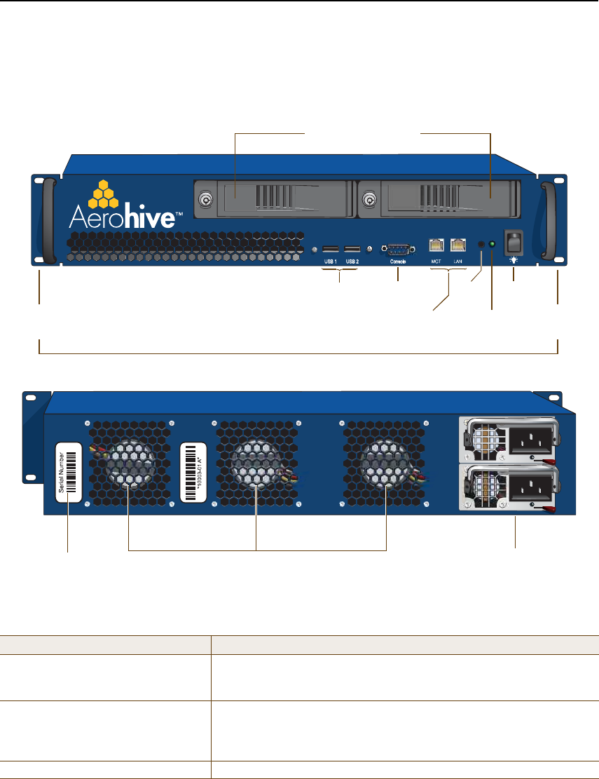
Chapter 6 The High Capacity HiveManager Platform
68 Aerohive
PRODUCT OVERVIEW
The Aerohive High Capacity HiveManager is a central management system for configuring and monitoring HiveAPs.
You can see its hardware components in Figure1 and read a description of each component in Table1.
Figure 1 High Capacity HiveManager Hardware Components
Table 1 High Capacity HiveManager Component Descriptions
Component Description
Hard Disk Drive TraysThe two hard disk drive trays contain first-level RAID (Redundant Array of
Independent Drives) mirrored hard disk drives to provide fault tolerance,
data reliability, and increased performance.
Front Mounting BracketsWhen used with the rack mounting kit, the two front mounting brackets
allow you to mount the High Capacity HiveManager in a standard 19"
(48.26 cm) equipment rack. For rack mounting instructions, see "Rack
Mounting the High Capacity HiveManager" on page70.
USB PortsThe USB ports are reserved for internal use.
USB
Ports
Console
Port
Power
LED
MGT and LAN
Ethernet Ports
System FansSerial Number
Label
Front Panel
Rear Panel
Front
Mounting
Bracket
Power
Switch
Hard Disk Drive Trays
Reset
Button Front
Mounting
Bracket
Dual AC Power
Supplies

Deployment Guide 69
PRODUCT OVERVIEW
Console Port A male DB-9 serial port to which you can make a console connection using
an RS-232 (or "null modem") cable. The pin assignments are the same as
those on the HiveManager and on the HiveAP (see "Ethernet and Console
Ports" on page26).
The management station from which you make a serial connection to the
HiveManager must have a VT100 emulation program, such as Tera Term
Pro© (a free terminal emulator) or Hilgraeve Hyperterminal® (provided
with Windows® operating systems). The following are the serial
connection settings: bits per second: 9600, data bits: 8, parity: none,
stop bits: 1, flow control: none. The default login name is admin and the
password is aerohive. After making a connection, you can access the
Linux operating system.
MGT and LAN Ethernet PortsThe MGT and LAN Ethernet ports are compatible with 10/100/1000-Mbps
connections, automatically negotiate half- and full-duplex mode with the
connecting devices, and support RJ-45 connectors. They are autosensing
and automatically adjust to straight-through and cross-over Ethernet
cables. The two ports allow you to separate traffic between the
HiveManager and its administrators from traffic between the
HiveManager and the HiveAPs it manages. The wiring terminates the
same way as that on the standard capacity HiveManager (see "Ethernet
and Console Ports" on page63).
Reset ButtonThe reset button allows you to reboot the High Capacity HiveManager.
Insert a paper clip, or something similar, into the hole and press the reset
button between 1 and 5 seconds. After releasing the button, the Power
LED goes dark, and then glows steady amber while the software loads and
the system performs a self-test. After the software finishes loading, the
Power LED glows steady green
Power LEDThe power LED conveys the operational states for the system power:
dark= no power; steady green = powered on.
On/Off Switch The on and off switch controls the power to the HiveManager.
Serial Number Label The serial number label contains the serial number for the device.
System Fans The three system fans maintain an optimum operating temperature. Be
sure that air flow through the system fan vents is not obstructed.
Dual AC Power Supplies There are two power supplies. Each three-prong AC power inlet is a C14
chassis plug through which you can connect the HiveManager to a 100 –
240-volt AC power source using the 10-amp/125-volt IEC power cords that
ship with the product. By cabling each power supply to a different
source, they provide redundancy in the event of a single power failure.
Each power supply has a fan that maintains its temperature. It is
important that nothing obstructs the air flow to these fans so that the
power supplies do not overheat.
Component Description
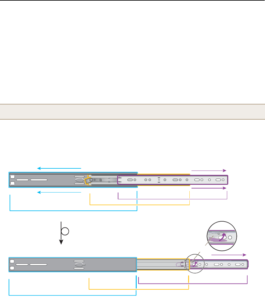
Chapter 6 The High Capacity HiveManager Platform
70 Aerohive
RACK MOUNTINGTHE HIGH CAPACITY HIVEMANAGER
Use the rack mounting kit to mount the High Capacity HiveManager in a standard 19" (48 cm) equipment rack. The
rack mounting kit contains the following items:
•(2) slide sets (each consisting of an outer slide, inner slide, and chassis rail)
•(2) rear mounting brackets
•(4) bar nuts
•(4) locator pins
•(6) slot-head machine screws with 8-32 threads – for attaching the mounting brackets to the outer slides
•(14) cross-head machine screws with 10-32 threads – for attaching the chassis rails to the HiveManager, and
the front and the rear mounting brackets to equipment rack rails with tapped holes or to the enclosed bar
nuts when the rack rails have round holes
1.After checking that the mounting kit contains the above parts, separate the chassis rails from each slide set, as
shown in Figure2.
Figure 2 Separating the Chassis Rail from the Nested Slides
2.Position one of the chassis rails so that the slide stop is near the HiveManager mounting bracket near the front
panel and the front and rear holes in the chassis rail align with the holes in the side of the HiveManager. Use
three of the cross-head screws to secure the chassis rail to the HiveManager chassis as shown in Figure3 on
page71.
Note: Because of the weight of the device (34 lb./ 15.42 kg without rails) , two people are required to rack
mount it safely.
Ñ«¬»® Í´·¼»
ײ²»® Í´·¼»
ݸ¿--·- ο·´
Û¨¬»²¼ ¬¸» ¬»´»-½±°·²¹ °·»½»- ±º ¬¸»
-´·¼» -»¬ ¬± ¬¸» ´»º¬ ¿²¼ ®·¹¸¬ò
Ñ«¬»® Í´·¼»
ײ²»® Í´·¼»
ݸ¿--·- ο·´
Í©·ª»´ ¬¸» ½¿¬½¸ ¬± ®»´»¿-» ¬¸» ½¸¿--·- ®¿·´ô
¿²¼ ¬¸»² -´·¼» ·¬ ½±³°´»´»¬»´§ ¿©¿§ º®±³ ¬¸»
²»-¬»¼ -´·¼»-ò
Ì«®² ±ª»®ò
Ý¿¬½¸
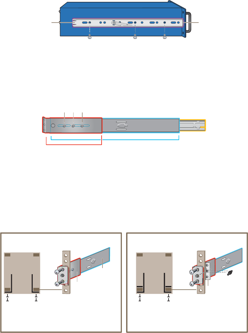
Deployment Guide 71
RACK MOUNTINGTHE HIGH CAPACITY HIVEMANAGER
Figure 3 Attaching the Chassis Rail to the HiveManager
3.Secure the other chassis rail to the other side of the HiveManager.
4.Use three slot-head screws to attach the rear mounting bracket to the outer slide. Insert the screws through the
rounded slots in the outer slide into the threaded holes in the bracket and tighten them as shown in Figure4.
Figure 4 Attaching the Rear Bracket to the Outer Slide
5.Use the remaining three slot-head screws to attach the other rear mounting bracket to the other outer slide.
6.Fasten the rear mounting brackets—and the slides attached to them—to the rear equipment rack rails.
Depending on the type of holes in the equipment rack, use one of the following methods:
•For tapped (threaded) holes, use two screws to fasten the brackets directly to the rack rails. Use the
cross-head screws (with 10-32 threads) if they fit the holes in the rack.
•For round holes, use the cross-head screws to fasten the brackets through the holes in the rack rails to the
bar nuts. You can use the locator pins to help keep the bar nuts aligned to the holes. See Figure5.
Figure 5 Fastening the Rear Mounting Brackets to the Rack Rails
д¿½» ¬¸» -´·¼» -¬±°
¿¹¿·²-¬ ¬¸» º®±²¬
³±«²¬·²¹ ¾®¿½µ»¬ò
ݸ¿--·- ο·´
½®±--󸻿¼ ³¿½¸·²» -½®»©- ©·¬¸ ïðóíî ¬¸®»¿¼-
Ñ«¬»® Í´·¼»
ײ²»® Í´·¼»
Ë-» ¬¸®»» -´±¬ó¸»¿¼ -½®»©- ¬± -»½«®» ±²»
±º ¬¸» ®»¿® ¾®¿½µ»¬- ¬± ¬¸» ±«¬»® -´·¼»ò
λ¿® Þ®¿½µ»¬
λ¿® ®¿·´
©·¬¸ ®±«²¼ ¸±´»-
Þ¿® Ò«¬
Ô±½¿¬±® з²
Ú±® »¯«·°³»²¬ ®¿½µ- ©·¬¸ ®±«²¼ ¸±´»-ô °´¿½» ¿ ¾¿® ²«¬
±² ¬¸» ±°°±-·¬» -·¼» ±º ¬¸» ®»¿® ®¿·´ º®±³ ¬¸» ¾®¿½µ»¬ò
øDZ« ½¿² «-» ¿ ´±½¿¬±® °·² ¬± ¸»´° µ»»° ¬¸» ²«¬ ¾¿®
¿´·¹²»¼ ©·¬¸ ¬¸» ¸±´»-ò÷ ̸»² -½®»© ¬¸» ¾®¿½µ»¬
¬¸®±«¹¸ ¬¸» ®¿·´ ·²¬± ¬¸» ¬¸®»¿¼»¼ ¸±´»- ·² ¬¸» ¾¿® ²«¬ò
λ¿® Þ®¿½µ»¬
λ¿® ®¿·´
©·¬¸ ¬¿°°»¼ ¸±´»-
Ñ«¬»® Í´·¼»
Û¯«·°³»²¬ ο½µ
ø¾·®¼Ž- »§» ª·»©÷
Ú®±²¬
λ¿®
Ú±® »¯«·°³»²¬ ®¿½µ- ©·¬¸ ¬¿°°»¼ ¸±´»-ô -½®»© ¬¸» ®»¿®
¾®¿½µ»¬- ¬± ¬¸» ®»¿® ®¿½µ ®¿·´- ¼·®»½¬´§ò ײ ¬¸·- ½¿-»ô §±«
¼± ²±¬ ²»»¼ ¬± «-» ¬¸» ¾¿® ²«¬- ¿²¼ ´±½¿¬±® °·²- ¬¸¿¬
¿®» °®±ª·¼»¼ ·² ¬¸» ®¿½µ ³±«²¬·²¹ µ·¬ò
ͽ®»©-
Þ®¿½µ»¬-
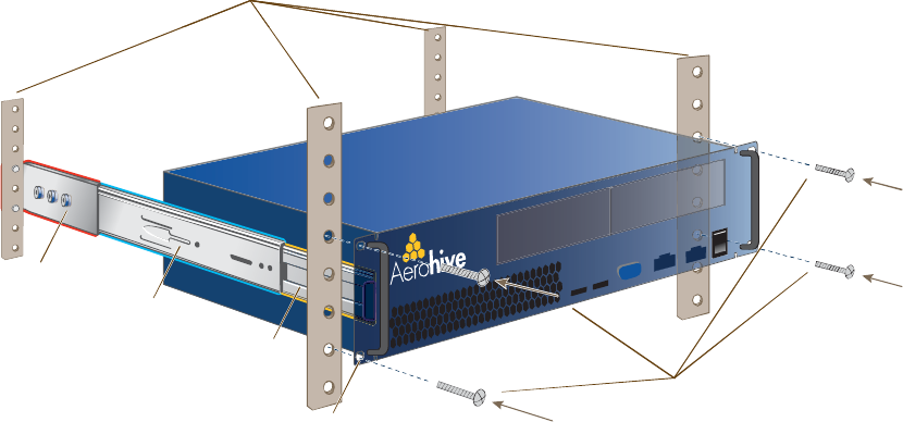
Chapter 6 The High Capacity HiveManager Platform
72 Aerohive
7.From the front of the equipment rack, guide the chassis rails on the sides of the HiveManager into the inner
slides. Then push the HiveManager into the rack until the front mounting brackets are flush against the front
rack rails.
8.Using four screws—two for each of the front brackets—fasten the HiveManager to the equipment rack as shown
in Figure6. If the rack has round holes, use the two remaining nut bars (and locator pins) and thread the screws
through the rack rails into them.
Figure 6 Mounting the HiveManager in an Equipment Rack
The HiveManager is now securely mounted to the front and rear rails of the equipment rack.
Screws
Front
Mounting Bracket
Rack Rails
Outer Slide
Inner Slide (over
the chassis rail)
Rear
Mounting Bracket
Screws
Front
Mounting Bracket
Rack Rails
Outer Slide
Inner Slide (over
the chassis rail)
Rear
Mounting Bracket
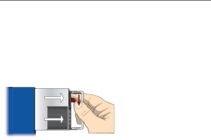
Deployment Guide 73
REPLACING POWER SUPPLIES
REPLACING POWER SUPPLIES
The high capacity HiveManager has a pair of redundant, hot-swappable power supplies. If one of the power supplies
fails, the other will continue to power the device. When a a power supply fails, a continuous beeping alarm sounds
and the power LED glows amber. To replace the failed power supply, do the following:
1.Disconnect the failed power supply from the power source.
2.Lower the handle to a horizontal position.
3.With your index finger, press the red release lever to the left.
4.While holding the release lever to the left, grip the handle between your thumb and second finger, and pull the
power supply straight out. See Figure7.
Figure 7 Removing a Power Supply
5.Insert a working power supply into the vacant bay and push it straight in until it is fully seated.
The red release automatically slides back to the right to secure the power supply in place.
6.Connect the power supply to the power source.
б©»® Í«°°´§
λ¿® ±º Ø·¹¸ Ý¿°¿½·¬§ Ø·ª»Ó¿²¿¹»® ø¾·®¼Ž- »§» ª·»©÷
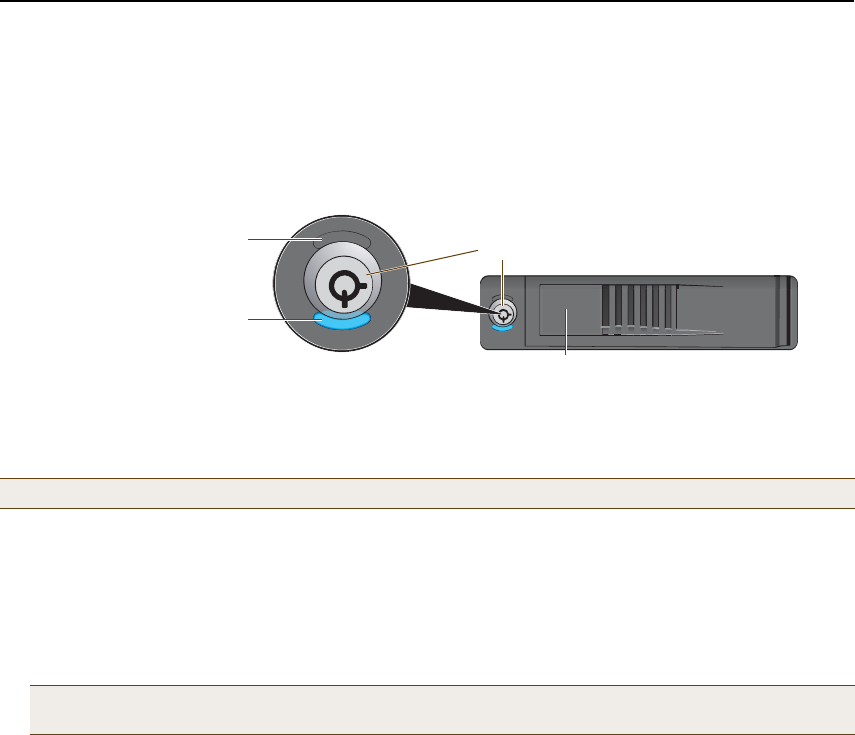
Chapter 6 The High Capacity HiveManager Platform
74 Aerohive
REPLACING HARD DISK DRIVES
To provide fault tolerance from disk errors and single disk failure, the high capacity HiveManager uses level 1 RAID
(Redundant Array of Independent Drives) HDDs (hard disk drives). Each HDD holds identical data, the data that is
written to one disk being mirrored to the other. The lower LEDs on the front of each HDD flash in unison to indicate
that they are writing data to memory. The upper LEDs indicate that they have power. See Figure8.
Figure 8 Hard Disk Drive LEDs
If you notice that only one of the lower LEDs is flashing while the other is dark, then there is a HDD failure. Although
the HiveManager can continue with just one operational HDD, you should replace the faulty HDD soon.
1.Turn off the HiveManager.
2.Unlock the HDD tray door for the disk that you want to replace.
3.Pull the tab on the left side of the door, and open the door, swivelling it on the hinge along its right side.
As you open the door, the HDD tray automatically extends.
4.Remove the failed HDD and insert a replacement
5.Close the door and lock it again.
6.Connect a serial cable to the console port
7.Connect one end of an RS-232 serial cable to the male DB-9 console port on the HiveManager and other end to
the serial port (or COM port) on your management system.
8.Start a serial connection as explained in "Changing Network Settings" on page79.
9.Turn on the HiveManager.
10.While it is booting up, press and hold down the CTRL+A keys until the utility console appears.
11.From the main menu, select Manage Arrays. (An array is the logical representation of a physical HDD unit.)
12.From the list of arrays, select the one that you want to rebuild.
13.Press CTRL+R to rebuild it.
The rebuild process takes about 30 minutes. When done, the utility console notifies you with a message.
14.Confirm that the process is complete.
The HiveManager continues booting up with the new HDD replacement in operation.
Note: HiveManager HDDs are not hot swappable. You must turn off the power before replacing a HDD.
Note: The replacement disk drive must be new or, if it has been used, there must not be a root file system on
it. Also, it must be the same size as or bigger than the other disk drive.
Upper LED: Power Status
(Illuminates when the
HDD first receives power)
Lower LED: HDD Activity
(Illuminates when writing
to memory)
Hard Disk Drive TrayLock
Tab

Deployment Guide 75
DEVICE, POWER,AND ENVIRONMENTAL SPECIFICATIONS
DEVICE, POWER,AND ENVIRONMENTAL SPECIFICATIONS
Understanding the range of specifications for the high capacity HiveManager is necessary for the optimal
deployment and operation of the device. The following specifications describe the physical features and hardware
components, the electrical requirements for the power supply and cord, and the temperature and humidity ranges
in which the device can operate.
Device Specifications
•Form factor: 2U rack-mountable device
•Chassis dimensions: 16 13/16" W x 3 1/2" H x 17" D (42.7 cm W x 8.9 cm H x 43.2 cm D)
•Weight: 34 lb. (15.42 kg)
•Serial port: male DB-9 RS-232 port (bits per second:9600, data bits: 8, parity: none, stop bits: 1, flow control:
none)
•USB port: standard Type A USB 2.0 port
•Ethernet ports: MGT and LAN — autosensing 10/100/1000Base-T Mbps
Power Specifications
•Redundant ATX (Advanced Technology Extended) autoswitching power supplies with PFC (power factor
corrector):
•Input: 100 – 240 VAC
•Output: 700 watts
•Power supply cords: Standard three conductor SVT 18AWG cords with an NEMA5-15P three-prong male plug and
three-pin socket
Environmental Specifications
•Operating temperature: 32 to 140 degrees F (0 to 60 degrees C)
•Storage temperature: -4 to 176 degrees F (-20 to 80 degrees C)
•Relative Humidity: 10% – 90% (noncondensing)
Chapter 6 The High Capacity HiveManager Platform
76 Aerohive
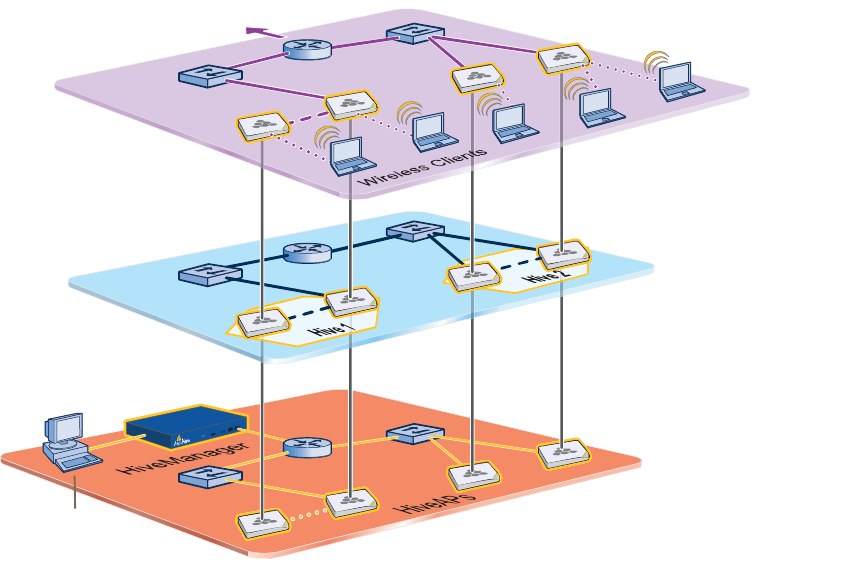
Deployment Guide 77
Chapter 7Using HiveManager
You can conceptualize the Aerohive cooperative control architecture as consisting of three broad planes of
communication. On the data plane, wireless clients gain network access by forming associations with HiveAPs. On
the control plane, HiveAPs communicate with each other to coordinate functions such as best-path forwarding, fast
roaming, and automatic RF (radio frequency) management. On the management plane, HiveManager provides
centralized configuration, monitoring, and reporting of multiple HiveAPs. These three planes are shown in Figure1.
Figure 1 Three Communication Planes in the Aerohive Cooperative Control Architecture
As you can see in Figure1, HiveManager operates solely on the management plane. Any loss of connectivity between
HiveManager and the HiveAPs it manages only affects HiveAP manageability; such a loss has no impact on
communications occurring on the control and data planes.
̸» ³¿²¿¹»³»²¬
°´¿²» ·- ¬¸» ´±¹·½¿´ ¼·ª·-·±² ±º
¿¼³·²·-¬®¿¬·ª» ¬®¿ºº·½ ®»´¿¬·²¹ ¬± ¬¸»
½±²º·¹«®¿¬·±² ¿²¼ ³±²·¬±®·²¹ ±º Ø·ª»ßÐ-ò Ú®±³ ¿
³¿²¿¹»³»²¬ -§-¬»³ô ¿² ¿¼³·² ½¿² «-» ¬¸» Ø·ª»Ó¿²¿¹»® ¬±
½±²º·¹«®»ô ³¿·²¬¿·²ô ¿²¼ ³±²·¬±® ³«´¬·°´» Ø·ª»ßÐ-ô »--»²¬·¿´´§ ½±±®¼·ó
²¿¬·²¹ ¬¸» ½±²¬®±´ ¿²¼ ¼¿¬¿ °´¿²»- º®±³ ¿ -·²¹´»ô ½»²¬®¿´ ´±½¿¬·±²ò
Ü¿¬¿ д¿²»
ݱ²¬®±´ д¿²»
Ó¿²¿¹»³»²¬ д¿²»
̸» ¼¿¬¿ °´¿²»
·- ¬¸» ´±¹·½¿´ ¼·ª·-·±² ±º
©·®»´»-- ½´·»²¬ ¬®¿ºº·½ ø«-»® ¼¿¬¿÷
¬®¿ª»®-·²¹ ¿ ©·®»´»--ó¬±ó©·®»¼ ÔßÒò Ì®¿ºº·½
·² ¬¸» ¼¿¬¿ °´¿²» º±´´±©- ±°¬·³¿´ °¿¬¸-
¬¸¿¬ ª¿®·±«- ³»½¸¿²·-³- ·² ¬¸» ½±²¬®±´
°´¿²» ¼»¬»®³·²»ò
̸» ½±²¬®±´ °´¿²» ·-
¬¸» ´±¹·½¿´ ¼·ª·-·±² ±º ¬®¿ºº·½ ¬¸¿¬
¸·ª» ³»³¾»®- «-» ¬± ½±´´¿¾±®¿¬» ±² ¸±©
¾»-¬ ¬± º±®©¿®¼ «-»® ¼¿¬¿ô ½±±®¼·²¿¬»
®¿¼·± º®»¯«»²½·»-ô ¿²¼ °®±ª·¼» ´¿§»®óî
¿²¼ ´¿§»®óí ®±¿³·²¹ ½¿°¿¾·´·¬·»- ©·¬¸
»¿½¸ ±¬¸»®ò
̱ ¬¸» ©·®»¼
²»¬©±®µ òòò
Ó¿²¿¹»³»²¬
ͧ-¬»³
Chapter 7 Using HiveManager
78 Aerohive
This chapter explains how to do the following basic tasks:
•Use the console port to change the network settings for the MGT and LAN interfaces
•Power on HiveManager and connect it to a network
•Make an HTTPS connection from your management system to HiveManager and log in to the GUI
It then introduces the HiveManager GUI and includes a summary of the configuration workflow. Finally, the chapter
concludes with procedures for updating HiveManager software and HiveAP firmware. The sections are as follows:
•"Installing and Connecting to the HiveManager GUI" on page79
•"Introduction to the HiveManager GUI" on page82
•"Cloning Configurations" on page83
•"Multiselecting" on page83
•"Sorting Displayed Data" on page84
•"HiveManager Configuration Workflow" on page85
•"Updating Software on HiveManager" on page86
•"Updating HiveOS Firmware" on page87
•"Updating HiveAPs in a Mesh Environment" on page88
Deployment Guide 79
INSTALLINGAND CONNECTINGTOTHE HIVEMANAGER GUI
INSTALLINGAND CONNECTINGTOTHE HIVEMANAGER GUI
To begin using the HiveManager GUI, you must first configure the MGT interface to be accessible on the network,
cable HiveManager and your management system (that is, your computer) to the network, and then make an HTTP
connection from your system to the MGT interface and download the GUI application.
Besides HiveManager and your management system, you need two or three Ethernet cables and a serial cable (or
"null modem"). The Ethernet cables can be standard cat3, cat5, cat5e, or cat6 cables with T568A or T568B
terminations and RJ-45 connectors. The serial cable must comply with the RS-232 standard and terminate on the
HiveManager end with a female DB-9 connector. (For more details, see "Ethernet and Console Ports" on page63.)
The GUI requirements for the management system are as follows:
•Minimum screen resolution of 1024 x 768 pixels
•Standard browser—Aerohive recommends Internet Explorer v7.0 or Mozilla Firefox v2.0.0 or later—with Flash
v9.0 or later, which is required for viewing charts with dynamically updated HiveAP alarms and wireless client
data
Your management system also needs a VT100 terminal emulation program, such as Tera Term Pro© (a free terminal
emulator) or Hilgraeve Hyperterminal® (provided with Windows® operating systems).
Changing Network Settings
To connect HiveManager to the network, you must first set the IP address/netmask of its MGT interface so that it is
in the subnet to which you plan to cable it. To do this, you can use the startup wizard that is available through the
console port.
1.Connect the power cable to a 100 – 240-volt power source, and turn on HiveManager. The power switch is on the
back panel of the device.
2.Connect one end of an RS-232 serial cable to the serial port (or COM port) on your management system.
3.Connect the other end of the cable to the male DB-9 console port on HiveManager.
4.On your management system, run a VT100 emulation program using the following settings:
•Bits per second (baud rate): 9600
•Data bits: 8
•Parity: none
•Stop bits: 1
•Flow control: none
5.Log in by entering the default user name (admin) and password (aerohive).
6.The HiveManager CLI shell launches and offers several options. To change network settings, enter 1
7.Follow the instructions to configure the IP address and netmask for the MGT (and LAN) interfaces, as well as the
default gateway, host name and domain name of HiveManager, and its primary DNS server.
When deciding to use one interface (MGT) or both (MGT and LAN), keep in mind that there are two main types
of traffic to and from HiveManager:
•HiveManager management traffic for admin access and SCP (Secure Copy) uploads
Note: HiveManager has two Ethernet interfaces—MGT and LAN. You can put just the MGT interface on the
network and use it for all types of traffic, or you can use both interfaces—which must be in different
subnets—and separate HiveManager management traffic (MGT) from HiveAP management traffic (LAN).
Note: The default IP address/netmask for the MGT interface is 192.168.2.10/24. For the LAN interface, it is
192.168.3.10/24. The default gateway IP address is 192.168.2.1. If you only use the MGT interface,
change the LAN interface network settings to 0.0.0.0/0. Do not assign it an IP address and netmask.