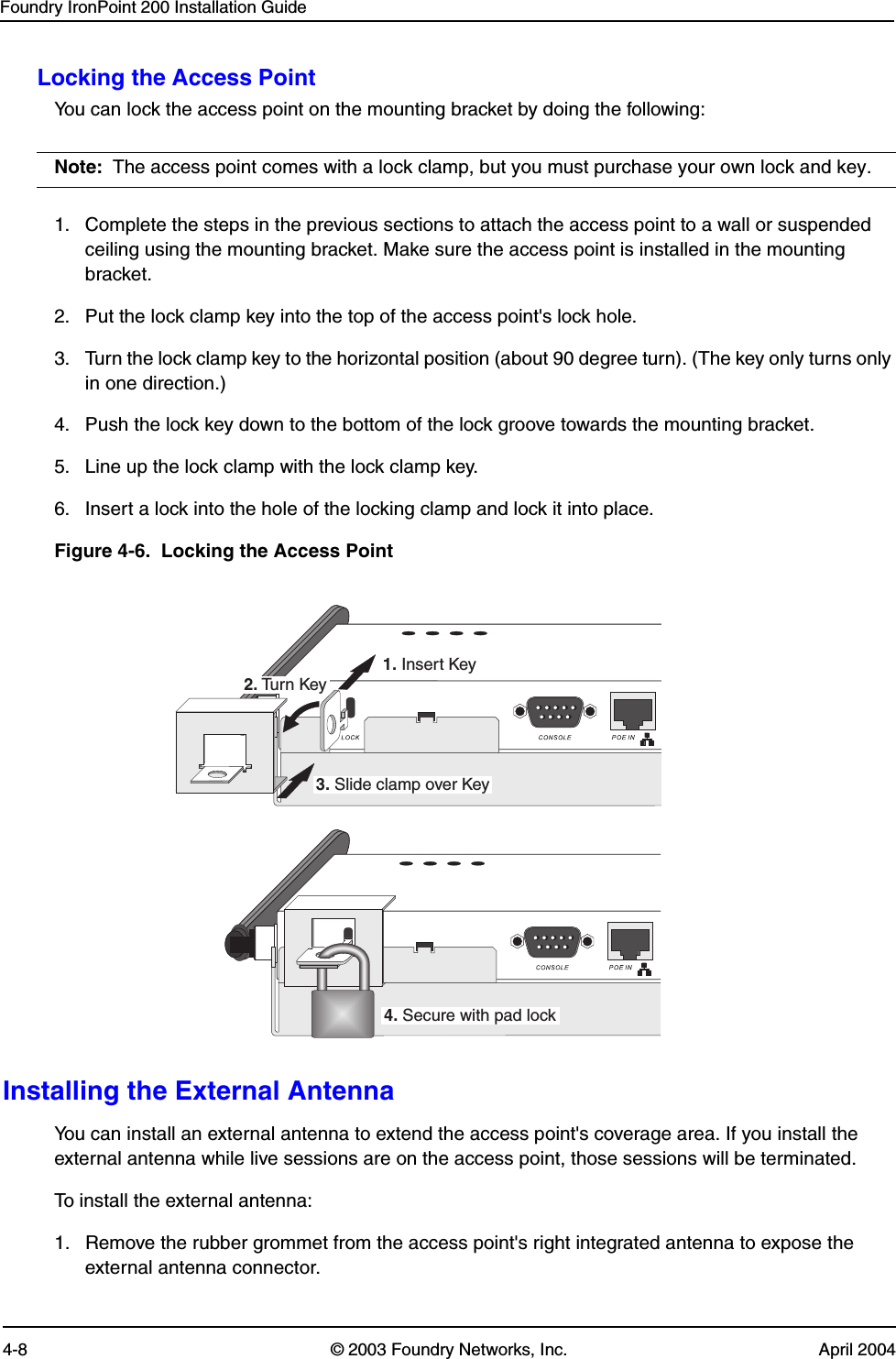
Accton Technology IP200EXT IronPoint 200 User Manual ip200install
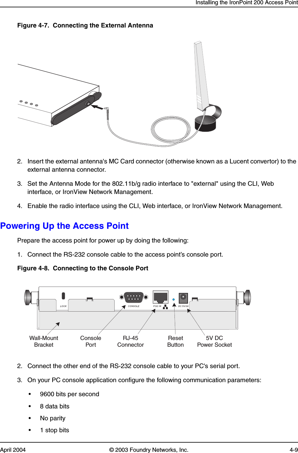
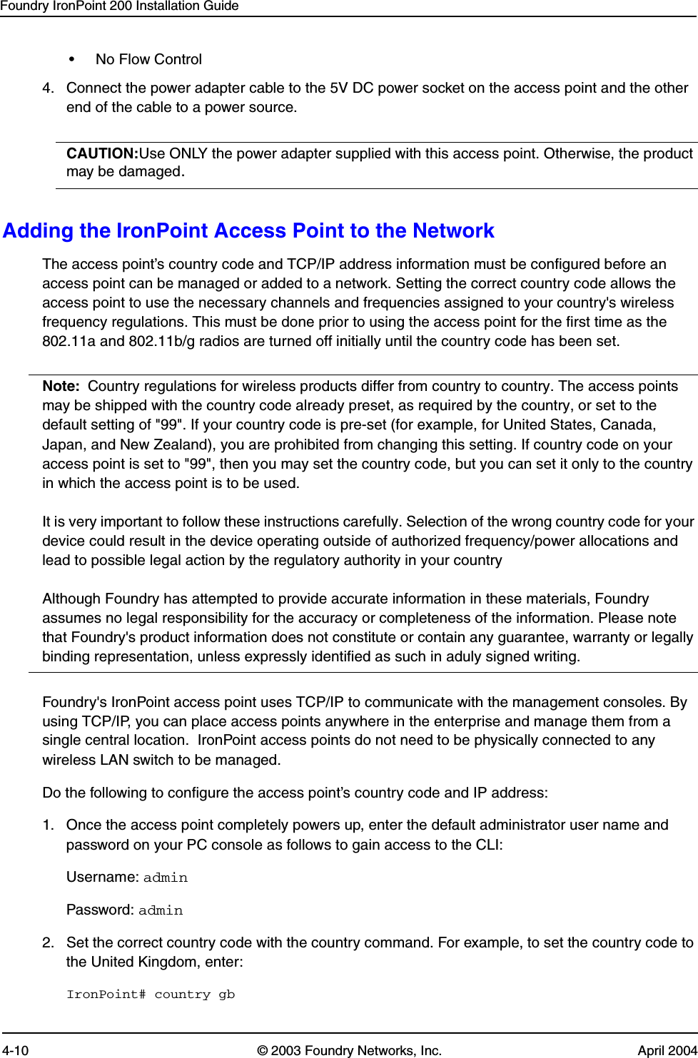
Accton Technology Corp IronPoint 200 ip200install
UserManual.wiki
>
Accton Technology
>
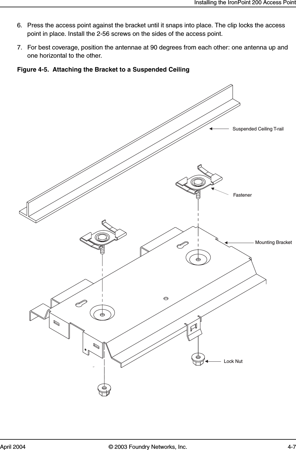
IP200EXT User Manual
user manual
Navigation menu
Upload a User Manual
Namespaces
Wiki Guide
HTML
PDF
Info
Views
User Manual
Discussion / Help
Navigation