Accton Technology IP200EXT IronPoint 200 User Manual ip200install
Accton Technology Corp IronPoint 200 ip200install
user manual

Foundry IronPoint 200
Installation Guide
2100 Gold Street
P.O. Box 649100
San Jose, CA 95164-9100
Tel 408.586.1700
Fax 408.586.1900
www.foundrynetworks.com
April 2004

Copyright © 2003 Foundry Networks, Inc. All rights reserved.
No part of this work may be reproduced in any form or by any means – graphic, electronic or
mechanical, including photocopying, recording, taping or storage in an information retrieval system –
without prior written permission of the copyright owner.
The trademarks, logos and service marks ("Marks") displayed herein are the property of Foundry or
other third parties. You are not permitted to use these Marks without the prior written consent of
Foundry or such appropriate third party.
Foundry Networks, BigIron, FastIron, IronView, JetCore, NetIron, ServerIron, TurboIron, IronWare, EdgeIron,
IronPoint, the Iron family of marks and the Foundry Logo are trademarks or registered trademarks of
Foundry Networks, Inc. in the United States and other countries.
All other trademarks mentioned in this document are the property of their respective owners.

April 2004 © 2003 Foundry Networks, Inc. iii
Compliances
FCC - Class B
This equipment has been tested and found to comply with the limits for a Class B digital device, pursuant to Part
15 of the FCC Rules. These limits are designed to provide reasonable protection against harmful interference in
a residential installation. This equipment generates, uses and can radiate radio frequency energy and, if not
installed and used in accordance with the instructions, may cause harmful interference to radio communica-
tions. However, there is no guarantee that interference will not occur in a particular installation. If this equipment
does cause harmful interference to radio or television reception, which can be determined by turning the equip-
ment off and on, the user is encouraged to try to correct the interference by one of the following measures:
• Reorient or relocate the receiving antenna
• Increase the separation between the equipment and receiver
• Connect the equipment into an outlet on a circuit different from that to which the receiver is connected
• Consult the dealer or an experienced radio/TV technician for help
FCC Caution: Any changes or modifications not expressly approved by the party responsible for compliance
could void the user's authority to operate this equipment. This device complies with Part 15 of the FCC Rules.
Operation is subject to the following two conditions: (1) This device may not cause harmful interference, and (2)
this device must accept any interference received, including interference that may cause undesired operation.
IMPORTANT NOTE:
FCC Radiation Exposure Statement
This equipment complies with FCC radiation exposure limits set forth for an uncontrolled environment. This
equipment should be installed and operated with a minimum distance of 20 centimeters (8 inches) between the
radiator and your body. This transmitter must not be co-located or operating in conjunction with any other
antenna or transmitter.
FCC Channel Use Statement:
The equipment version marketed in US is restricted to usage of the channels 1- 11 only.
Wireless 2.4 Ghz and 5 GHz Band Statements:
As the IronPoint can operate in the 5150-5250 MHz frequency band it is limited by the FCC, Industry Canada
and some other countries to indoor use only so as to reduce the potential for harmful interference to co-channel
Mobile Satellite systems.
High power radars are allocated as primary users (meaning they have priority) of the 5250-5350 MHz and
5650-5850 MHz bands. These radars could cause interference and/or damage to the IronPoint when used in
Canada.
The term “IC:” before the radio certification number only signifies that Industry Canada technical specifications
were met.

Foundry IronPoint 200 Installation Guide
iv © 2003 Foundry Networks, Inc. April 2004
Industry Canada - Class B
This digital apparatus does not exceed the Class B limits for radio noise emissions from digital apparatus as set
out in the interference-causing equipment standard entitled “Digital Apparatus,” ICES-003 of Industry Canada.
Cet appareil numérique respecte les limites de bruits radioélectriques applicables aux appareils numériques de
Classe B prescrites dans la norme sur le matérial brouilleur: “Appareils Numériques,” NMB-003 édictée par
l’Industrie.
Japan VCCI Class B
EC Declaration of Conformity
Contact Foundry Networks at:
Foundry Networks, Inc.
2100 Gold Street
P.O. Box 649100
San Jose, CA 95164-9100
Marking by the above symbol indicates compliance with the Essential Requirements of the R&TTE Directive of
the European Union (1999/5/EC). This equipment meets the following conformance standards:
• EN 60950 (IEC 60950) - Product Safety
• EN 301 893 - Technical requirements for 5 GHz radio equipment
• EN 300 328 - Technical requirements for 2.4 GHz radio equipment
• EN 301 489-1 / EN 301 489-17 - EMC requirements for radio equipment
Countries of Operation & Conditions of Use in the European Community
This device is intended to be operated in all countries of the European Community. It is intended only for indoor
use. License requirements and allowed channels of operation apply in some countries as described below:
Note: The user must use the configuration utility provided with this product to ensure the channels
of operation are in conformance with the spectrum usage rules for European Community countries
as described below.
• This device requires that the user or installer properly enter the current country of operation in the Command
Line Interface (CLI) as described in the user guide, before operating this device.
• This device will automatically limit the allowable channels determined by the current country of operation.
Incorrectly entering the country of operation may result in illegal operation and may cause harmful interference
to other system. The user is obligated to ensure the device is operating according to the channel limitations,
indoor/outdoor restrictions and license requirements for each European Community country as described in
this document.
• This device employs a radar detection feature required for European Community operation in the 5 GHz band.
This feature is automatically enabled when the country of operation is correctly configured for any European
Community country. The presence of nearby radar operation may result in temporary interruption of operation
of this device. The radar detection feature will automatically restart operation on a channel free of radar.
• The 5 GHz Turbo Mode feature is not allowed for operation in any European Community country. The current
setting for this feature is found in the 5 GHz 802.11a Radio Settings Window as described in the user guide.
• The 5 GHz radio's AutoChannelSelect/SmartSelect setting described in the user guide must always remain
enabled to ensure that automatic 5 GHz channel selection complies with European requirements. The current
setting for this feature is found in the 5 GHz 802.11a Radio Settings Window as described in the user guide.
0560

Compliances
April 2004 © 2003 Foundry Networks, Inc. v
• This device is restricted to indoor use when operated in the European Community using the 5.15 - 5.35 GHz
band: Channels 36, 40, 44, 48, 52, 56, 60, 64. See table below for allowed 5 GHz channels by country.
• This device is restricted for indoor use when operated in all countries of the European Community using the
2.4 GHz band: Channels 1 - 13.
Operation Using 5 GHz Channels in the European Community
The user/installer must use the provided configuration utility to check the current channel of operation and make
necessary configuration changes to ensure operation occurs in conformance with European National spectrum
usage laws as described below and elsewhere in this document.
By selecting the appropriate country codes detailed on page 4-10 of this guide you will ensure the device oper-
ates within the frequency restrictions detailed above. You are responsible for ensuring the device is used
indoors-only and for private use only as applicable
Transmit Power Control (TPC) for 5GHz Operation
The end-user must operate this device in accordance with European regulatory requirements for Transmit
Power Control. This device employs Transmit Power Control (TPC) to reduce the potential for interference to
other communication systems operating in the 5 GHz frequency bands. The TPC feature implemented in this
wireless LAN device must be configured by the end-user when operating in any European Community country.
The required configuration procedure for TPC is found in the user guide for this product.
Note: The TPC procedure should be repeated when relocating this wireless device within the
current wireless network or to a wireless network in a new location.
Declaration of Conformity in Languages of the European Community
Allowed 5GHz Channels in Each European Community Country
Allowed Frequency Bands Allowed Channel Numbers Countries
5.15 - 5.25 GHz* 36, 40, 44, 48 Austria, Belgium
5.15 - 5.35 GHz* 36, 40, 44, 48, 52, 56, 60, 64 France, Switzerland, Liechtenstein
5.15 - 5.35* & 5.470 - 5.725 GHz 36, 40, 44, 48, 52, 56, 60, 64, 100,
104, 108, 112, 116, 120, 124, 128,
132, 136, 140
Denmark, Finland, Germany,
Iceland, Ireland, Italy, Luxembourg,
Netherlands, Norway, Portugal,
Spain, Sweden, U.K.
5 GHz Operation Not Allowed None Greece
* Outdoor operation is not allowed using 5.15-5.35 GHz bands (Channels 36 to 64).
English Hereby, Foundry Networks, declares that this Radio LAN device is in compliance with the
essential requirements and other relevant provisions of Directive 1999/5/EC.
Finnish Valmistaja Foundry Networks vakuuttaa täten että Radio LAN device tyyppinen laite on
direktiivin 1999/5/EY oleellisten vaatimusten ja sitä koskevien direktiivin muiden ehtojen
mukainen.
Dutch Hierbij verklaart Foundry Networks dat het toestel Radio LAN device in overeenstemming
is met de essentiële eisen en de andere relevante bepalingen van richtlijn 1999/5/EG
Bij deze Foundry Networks dat deze Radio LAN device voldoet aan de essentiële eisen en
aan de overige relevante bepalingen van Richtlijn 1999/5/EC.
French Par la présente Foundry Networks déclare que l'appareil Radio LAN device est conforme
aux exigences essentielles et aux autres dispositions pertinentes de la directive 1999/5/CE

Foundry IronPoint 200 Installation Guide
vi © 2003 Foundry Networks, Inc. April 2004
Australia/New Zealand AS/NZS 4771
Contact Foundry Networks at:
Foundry Networks, Inc.
2100 Gold Street
P.O. Box 649100
San Jose, CA 95164-9100
Safety Compliance
Underwriters Laboratories Compliance Statement
Important! Before making connections, make sure you have the correct cord set. Check it (read the label on the
cable) against the following:
Swedish Härmed intygar Foundry Networks att denna Radio LAN device står I överensstämmelse
med de väsentliga egenskapskrav och övriga relevanta bestämmelser som framgår av
direktiv 1999/5/EG.
Danish Undertegnede Foundry Networks erklærer herved, at følgende udstyr Radio LAN device
overholder de væsentlige krav og øvrige relevante krav i direktiv 1999/5/EF
German Hiermit erklärt Foundry Networks, dass sich dieser/diese/dieses Radio LAN device in
Übereinstimmung mit den grundlegenden Anforderungen und den anderen relevanten
Vorschriften der Richtlinie 1999/5/EG befindet". (BMWi)
Hiermit erklärt Foundry Networks die Übereinstimmung des Gerätes Radio LAN device mit
den grundlegenden Anforderungen und den anderen relevanten Festlegungen der
Richtlinie 1999/5/EG. (Wien)
Greek Με την παρουσα Foundry Networks δηλωνει οτι radio LAN device συµµορφωνεται προσ
τισ ουσιωδεισ απαιτησεισ και τισ λοιπεσ σΧετικεσ διαταξεισ τησ οδηγιασ 1999/5/εκ
Italian Con la presente Foundry Networks dichiara che questo Radio LAN device è conforme ai
requisiti essenziali ed alle altre disposizioni pertinenti stabilite dalla direttiva 1999/5/CE.
Spanish Por medio de la presente Foundry Networks declara que el Radio LAN device cumple con
los requisitos esenciales y cualesquiera otras disposiciones aplicables o exigibles de la
Directiva 1999/5/CE
Portuguese Foundry Networks declara que este Radio LAN device está conforme com os requisitos
essenciais e outras disposições da Directiva 1999/5/CE.
Operating Voltage Cord Set Specifications
120 Volts UL Listed/CSA Certified Cord Set
Minimum 18 AWG
Type SVT or SJT three conductor cord
Maximum length of 15 feet
Parallel blade, grounding type attachment plug rated 15 A, 125 V
240 Volts (Europe
only)
Cord Set with H05VV-F cord having three conductors with minimum diameter of 0.75
mm2
IEC-320 receptacle
Male plug rated 10 A, 250 V
ACN 066 352010

Compliances
April 2004 © 2003 Foundry Networks, Inc. vii
The unit automatically matches the connected input voltage. Therefore, no additional adjustments are neces-
sary when connecting it to any input voltage within the range marked on the rear panel.
Wichtige Sicherheitshinweise (Germany)
1. Bitte lesen Sie diese Hinweise sorgfältig durch.
2. Heben Sie diese Anleitung für den späteren Gebrauch auf.
3. Vor jedem Reinigen ist das Gerät vom Stromnetz zu trennen. Verwenden Sie keine Flüssigoder Aerosol-
reiniger. Am besten eignet sich ein angefeuchtetes Tuch zur Reinigung.
4. Die Netzanschlu ßsteckdose soll nahe dem Gerät angebracht und leicht zugänglich sein.
5. Das Gerät ist vor Feuchtigkeit zu schützen.
6. Bei der Aufstellung des Gerätes ist auf sicheren Stand zu achten. Ein Kippen oder Fallen könnte Beschä-
digungen hervorrufen.
7. Die Belüftungsöffnungen dienen der Luftzirkulation, die das Gerät vor Überhitzung schützt. Sorgen Sie
dafür, daß diese Öffnungen nicht abgedeckt werden.
8. Beachten Sie beim Anschluß an das Stromnetz die Anschlußwerte.
9. Verlegen Sie die Netzanschlußleitung so, daß niemand darüber fallen kann. Es sollte auch nichts auf der
Leitung abgestellt werden.
10. Alle Hinweise und Warnungen, die sich am Gerät befinden, sind zu beachten.
11. Wird das Gerät über einen längeren Zeitraum nicht benutzt, sollten Sie es vom Stromnetz trennen. Somit
wird im Falle einer Überspannung eine Beschädigung vermieden.
12. Durch die Lüftungsöffnungen dürfen niemals Gegenstände oder Flüssigkeiten in das Gerät gelangen. Dies
könnte einen Brand bzw. elektrischen Schlag auslösen.
13. Öffnen sie niemals das Gerät. Das Gerät darf aus Gründen der elektrischen Sicherheit nur von authorisier-
tem Servicepersonal geöffnet werden.
14. Wenn folgende Situationen auftreten ist das Gerät vom Stromnetz zu trennen und von einer qualifizierten
Servicestelle zu überprüfen:
a. Netzkabel oder Netzstecker sind beschädigt.
b. Flüssigkeit ist in das Gerät eingedrungen.
c. Das Gerät war Feuchtigkeit ausgesetzt.
d. Wenn das Gerät nicht der Bedienungsanleitung entsprechend funktioniert oder Sie mit Hilfe dieser Anle-
itung keine Verbesserung erzielen.
e. Das Gerät ist gefallen und/oder das Gehäuse ist beschädigt.
f. Wenn das Gerät deutliche Anzeichen eines Defektes aufweist.
15. Stellen Sie sicher, daß die Stromversorgung dieses Gerätes nach der EN 60950 geprüft ist. Ausgang-
swerte der Stromversorgung sollten die Werte von AC 7,5-8V, 50-60Hz nicht über oder unterschreiten
sowie den minimalen Strom von 1A nicht unterschreiten.
Der arbeitsplatzbezogene Schalldruckpegel nach DIN 45 635 Teil 1000 beträgt 70dB(A) oder weniger.

Foundry IronPoint 200 Installation Guide
viii © 2003 Foundry Networks, Inc. April 2004

April 2004 © 2003 Foundry Networks, Inc. ix
Contents
Compliances . . . . . . . . . . . . . . . . . . . . . . . . . . . . . . . . . . . . . . . . . . . . . . . . . . . . . . . . . . . . . . . . . . . . iii
Chapter 1.
About This Guide . . . . . . . . . . . . . . . . . . . . . . . . . . . . . . . . . . . . . . . . . . . . . . . . . . . . . . . . . . . . . . .1-1
Audience . . . . . . . . . . . . . . . . . . . . . . . . . . . . . . . . . . . . . . . . . . . . . . . . . . . . . . . . . . . . . . . . . . .1-1
Nomenclature . . . . . . . . . . . . . . . . . . . . . . . . . . . . . . . . . . . . . . . . . . . . . . . . . . . . . . . . . . . . . . .1-1
How to Get Help . . . . . . . . . . . . . . . . . . . . . . . . . . . . . . . . . . . . . . . . . . . . . . . . . . . . . . . . . . . . .1-1
Foundry Networks Technical Support . . . . . . . . . . . . . . . . . . . . . . . . . . . . . . . . . . . . . . . . . .1-1
Web Access . . . . . . . . . . . . . . . . . . . . . . . . . . . . . . . . . . . . . . . . . . . . . . . . . . . . . . . . . . . . .1-1
E-mail Access . . . . . . . . . . . . . . . . . . . . . . . . . . . . . . . . . . . . . . . . . . . . . . . . . . . . . . . . . . . .1-2
Telephone Access . . . . . . . . . . . . . . . . . . . . . . . . . . . . . . . . . . . . . . . . . . . . . . . . . . . . . . . . .1-2
Warranty Coverage . . . . . . . . . . . . . . . . . . . . . . . . . . . . . . . . . . . . . . . . . . . . . . . . . . . . . . . . . . .1-2
Related Publications . . . . . . . . . . . . . . . . . . . . . . . . . . . . . . . . . . . . . . . . . . . . . . . . . . . . . . . . . .1-2
Chapter 2.
About the IronPoint 200 . . . . . . . . . . . . . . . . . . . . . . . . . . . . . . . . . . . . . . . . . . . . . . . . . . . . . . . . . .2-1
Overview . . . . . . . . . . . . . . . . . . . . . . . . . . . . . . . . . . . . . . . . . . . . . . . . . . . . . . . . . . . . . . . . . . .2-1
Radio Characteristics . . . . . . . . . . . . . . . . . . . . . . . . . . . . . . . . . . . . . . . . . . . . . . . . . . . . . .2-2
Management Options . . . . . . . . . . . . . . . . . . . . . . . . . . . . . . . . . . . . . . . . . . . . . . . . . . . . . .2-2
Description of Hardware . . . . . . . . . . . . . . . . . . . . . . . . . . . . . . . . . . . . . . . . . . . . . . . . . . . . . . .2-3
Ethernet Port . . . . . . . . . . . . . . . . . . . . . . . . . . . . . . . . . . . . . . . . . . . . . . . . . . . . . . . . . . . . .2-3
Antennas . . . . . . . . . . . . . . . . . . . . . . . . . . . . . . . . . . . . . . . . . . . . . . . . . . . . . . . . . . . . . . . .2-3
Optional External Antenna . . . . . . . . . . . . . . . . . . . . . . . . . . . . . . . . . . . . . . . . . . . . . . . . . .2-3
Status LEDs . . . . . . . . . . . . . . . . . . . . . . . . . . . . . . . . . . . . . . . . . . . . . . . . . . . . . . . . . . . . .2-4
Security Slot . . . . . . . . . . . . . . . . . . . . . . . . . . . . . . . . . . . . . . . . . . . . . . . . . . . . . . . . . . . . .2-5
Console Port . . . . . . . . . . . . . . . . . . . . . . . . . . . . . . . . . . . . . . . . . . . . . . . . . . . . . . . . . . . . .2-5
Reset Button . . . . . . . . . . . . . . . . . . . . . . . . . . . . . . . . . . . . . . . . . . . . . . . . . . . . . . . . . . . . .2-5
Power Connector . . . . . . . . . . . . . . . . . . . . . . . . . . . . . . . . . . . . . . . . . . . . . . . . . . . . . . . . .2-5
Features and Benefits . . . . . . . . . . . . . . . . . . . . . . . . . . . . . . . . . . . . . . . . . . . . . . . . . . . . . . . . .2-6

Foundry IronPoint 200 Installation Guide
x © 2003 Foundry Networks, Inc. April 2004
Connectivity . . . . . . . . . . . . . . . . . . . . . . . . . . . . . . . . . . . . . . . . . . . . . . . . . . . . . . . . . . . . . .2-6
Management . . . . . . . . . . . . . . . . . . . . . . . . . . . . . . . . . . . . . . . . . . . . . . . . . . . . . . . . . . . . .2-6
Chapter 3.
Network Planning . . . . . . . . . . . . . . . . . . . . . . . . . . . . . . . . . . . . . . . . . . . . . . . . . . . . . . . . . . . . . . .3-1
Network Topologies . . . . . . . . . . . . . . . . . . . . . . . . . . . . . . . . . . . . . . . . . . . . . . . . . . . . . . . . . . .3-1
Ad Hoc Wireless LAN (no AP or Bridge) . . . . . . . . . . . . . . . . . . . . . . . . . . . . . . . . . . . . . . . .3-1
Infrastructure Wireless LAN . . . . . . . . . . . . . . . . . . . . . . . . . . . . . . . . . . . . . . . . . . . . . . . . .3-2
Infrastructure Wireless LAN for Roaming Wireless PCs . . . . . . . . . . . . . . . . . . . . . . . . . . . .3-3
Chapter 4.
Installing the IronPoint 200 Access Point . . . . . . . . . . . . . . . . . . . . . . . . . . . . . . . . . . . . . . . . . . .4-1
Unpacking the IronPoint Access Point . . . . . . . . . . . . . . . . . . . . . . . . . . . . . . . . . . . . . . . . . . . .4-1
Installing the IronPoint Access Point . . . . . . . . . . . . . . . . . . . . . . . . . . . . . . . . . . . . . . . . . . . . . .4-1
Placing the Access Point on a Desktop or Shelf . . . . . . . . . . . . . . . . . . . . . . . . . . . . . . . . . .4-1
Attaching the Access Point to a Wall without the Mounting Bracket . . . . . . . . . . . . . . . . . . .4-2
Attaching the Access Point to a Wall Using the Mounting Bracket . . . . . . . . . . . . . . . . . . . .4-4
Attaching the Access Point to a Suspended Ceiling . . . . . . . . . . . . . . . . . . . . . . . . . . . . . . .4-6
Locking the Access Point . . . . . . . . . . . . . . . . . . . . . . . . . . . . . . . . . . . . . . . . . . . . . . . . . . .4-8
Installing the External Antenna . . . . . . . . . . . . . . . . . . . . . . . . . . . . . . . . . . . . . . . . . . . . . . . . . .4-8
Powering Up the Access Point . . . . . . . . . . . . . . . . . . . . . . . . . . . . . . . . . . . . . . . . . . . . . . . . . .4-9
Adding the IronPoint Access Point to the Network . . . . . . . . . . . . . . . . . . . . . . . . . . . . . . . . . .4-10
Chapter 5.
Making a Network Connection . . . . . . . . . . . . . . . . . . . . . . . . . . . . . . . . . . . . . . . . . . . . . . . . . . . .5-1
Connecting to a Network Device . . . . . . . . . . . . . . . . . . . . . . . . . . . . . . . . . . . . . . . . . . . . . . . . .5-1
Twisted-Pair Cable . . . . . . . . . . . . . . . . . . . . . . . . . . . . . . . . . . . . . . . . . . . . . . . . . . . . . . . . . . .5-1
Cabling Guidelines . . . . . . . . . . . . . . . . . . . . . . . . . . . . . . . . . . . . . . . . . . . . . . . . . . . . . . . .5-1
Connecting to a Switch, Hub, PC, or Server . . . . . . . . . . . . . . . . . . . . . . . . . . . . . . . . . . . . .5-1
Appendix A.
Troubleshooting . . . . . . . . . . . . . . . . . . . . . . . . . . . . . . . . . . . . . . . . . . . . . . . . . . . . . . . . . . . . . . . A-1
Diagnosing Access Point Indicators . . . . . . . . . . . . . . . . . . . . . . . . . . . . . . . . . . . . . . . . . . . . . A-1
Installation . . . . . . . . . . . . . . . . . . . . . . . . . . . . . . . . . . . . . . . . . . . . . . . . . . . . . . . . . . . . . . . . . A-1
Console Access . . . . . . . . . . . . . . . . . . . . . . . . . . . . . . . . . . . . . . . . . . . . . . . . . . . . . . . . . . . . . A-1
In-Band Access . . . . . . . . . . . . . . . . . . . . . . . . . . . . . . . . . . . . . . . . . . . . . . . . . . . . . . . . . . . . . A-2
Wireless Client Network Access . . . . . . . . . . . . . . . . . . . . . . . . . . . . . . . . . . . . . . . . . . . . . . . . A-2
Lost Password . . . . . . . . . . . . . . . . . . . . . . . . . . . . . . . . . . . . . . . . . . . . . . . . . . . . . . . . . . . . . . A-3
Reset the Access Point Default Settings . . . . . . . . . . . . . . . . . . . . . . . . . . . . . . . . . . . . . . . . . . A-3
Maximum Distance Tables . . . . . . . . . . . . . . . . . . . . . . . . . . . . . . . . . . . . . . . . . . . . . . . . . . . . A-4
Appendix B.
Cables . . . . . . . . . . . . . . . . . . . . . . . . . . . . . . . . . . . . . . . . . . . . . . . . . . . . . . . . . . . . . . . . . . . . . . . B-1
Specifications . . . . . . . . . . . . . . . . . . . . . . . . . . . . . . . . . . . . . . . . . . . . . . . . . . . . . . . . . . . . . . B-1
Twisted-Pair Cable and Pin Assignments . . . . . . . . . . . . . . . . . . . . . . . . . . . . . . . . . . . . . . . . . B-2

Contents
April 2004 © 2003 Foundry Networks, Inc. xi
100BASE-TX/10BASE-T Pin Assignments . . . . . . . . . . . . . . . . . . . . . . . . . . . . . . . . . . . . . B-2
Straight-Through Wiring . . . . . . . . . . . . . . . . . . . . . . . . . . . . . . . . . . . . . . . . . . . . . . . . . . . B-2
Crossover Wiring . . . . . . . . . . . . . . . . . . . . . . . . . . . . . . . . . . . . . . . . . . . . . . . . . . . . . . . . . B-3
Console Port Pin Assignments . . . . . . . . . . . . . . . . . . . . . . . . . . . . . . . . . . . . . . . . . . . . . . . . . B-3
Wiring Map for Serial Cable . . . . . . . . . . . . . . . . . . . . . . . . . . . . . . . . . . . . . . . . . . . . . . . . B-4
Appendix C.
Specifications . . . . . . . . . . . . . . . . . . . . . . . . . . . . . . . . . . . . . . . . . . . . . . . . . . . . . . . . . . . . . . . . . C-1
General Specifications . . . . . . . . . . . . . . . . . . . . . . . . . . . . . . . . . . . . . . . . . . . . . . . . . . . . . . . . C-1
Sensitivity . . . . . . . . . . . . . . . . . . . . . . . . . . . . . . . . . . . . . . . . . . . . . . . . . . . . . . . . . . . . . . C-3
Transmit Power . . . . . . . . . . . . . . . . . . . . . . . . . . . . . . . . . . . . . . . . . . . . . . . . . . . . . . . . . . C-4
Glossary
Index

Foundry IronPoint 200 Installation Guide
xii © 2003 Foundry Networks, Inc. April 2004

April 2004 © 2003 Foundry Networks, Inc. 1-1
Chapter 1
About This Guide
The IronPoint™ 200 Access Point is a device that allows wireless clients to connect to your
enterprise network. It is a full-featured access point that can be managed as a single device or by
IronView Network Manager, a network management tool that manages several Foundry devices on a
network.
This guide presents the procedures for installing the IronPoint™ 200 Access Point.
Audience
This guide is for system administrators with a working knowlege of wireless networks and network
management.
You should be familiar with switching and networking concepts.
Nomenclature
This guide uses the following typographical conventions to show information:
Warning: A warning calls your attention to a possible hazard that can cause injury or death.
Caution: A caution calls your attention to a possible hazard that can damage equipment.
Note: A note emphasizes an important fact or calls your attention to a dependency.
How to Get Help
If you need assistance, Foundry Networks is committed to ensuring that your investment in our
products remains cost-effective by offering a variety of support options.
Foundry Networks Technical Support
Foundry Networks technical support will ensure that the fast and easy access that you have come to
expect from your Foundry Networks products will be maintained.
Web Access
Point your browser to the following URL: http://www.foundrynetworks.com.

Foundry IronPoint 200 Installation Guide
1-2 © 2003 Foundry Networks, Inc. April 2004
Navigate to Services/Technical Support.
Click the Login button, then enter your user name and password to gain access to the Foundry
support site.
Note: Check with your sales account representative to determine how to obtain a valid user name
and password.
E-mail Access
Technical requests can also be sent to the e-mail address: support@foundrynet.com
Telephone Access
◆1.877.TURBOCALL (887.2622): United States
◆1.408.586.1881: Outside the United States
Warranty Coverage
Contact Foundry Networks using any of the methods listed above for information about the standard
and extended warranties.
Related Publications
Refer to the Foundry IronPoint 200 User Guide for instructions on how to configure and manage the
access point. Also refer to the Foundry Quick Start Guide for the minimum configuration required to
secure the IronPoint access point before placing it on the network.
April 2004 © 2003 Foundry Networks, Inc. 2-1
Chapter 2
About the IronPoint 200
Overview
Foundry’s IronPoint 200 is an IEEE 802.11a/g enterprise wireless access point that provides high-
speed data communications between the wired LAN and fixed, portable or mobile devices equipped
with an 802.11a, 802.11b, or 802.11g wireless network card.
The access point offers full network management capabilities through a command line interface for
initial configuration and troubleshooting, a Web interface, and Simple Network Management tools.
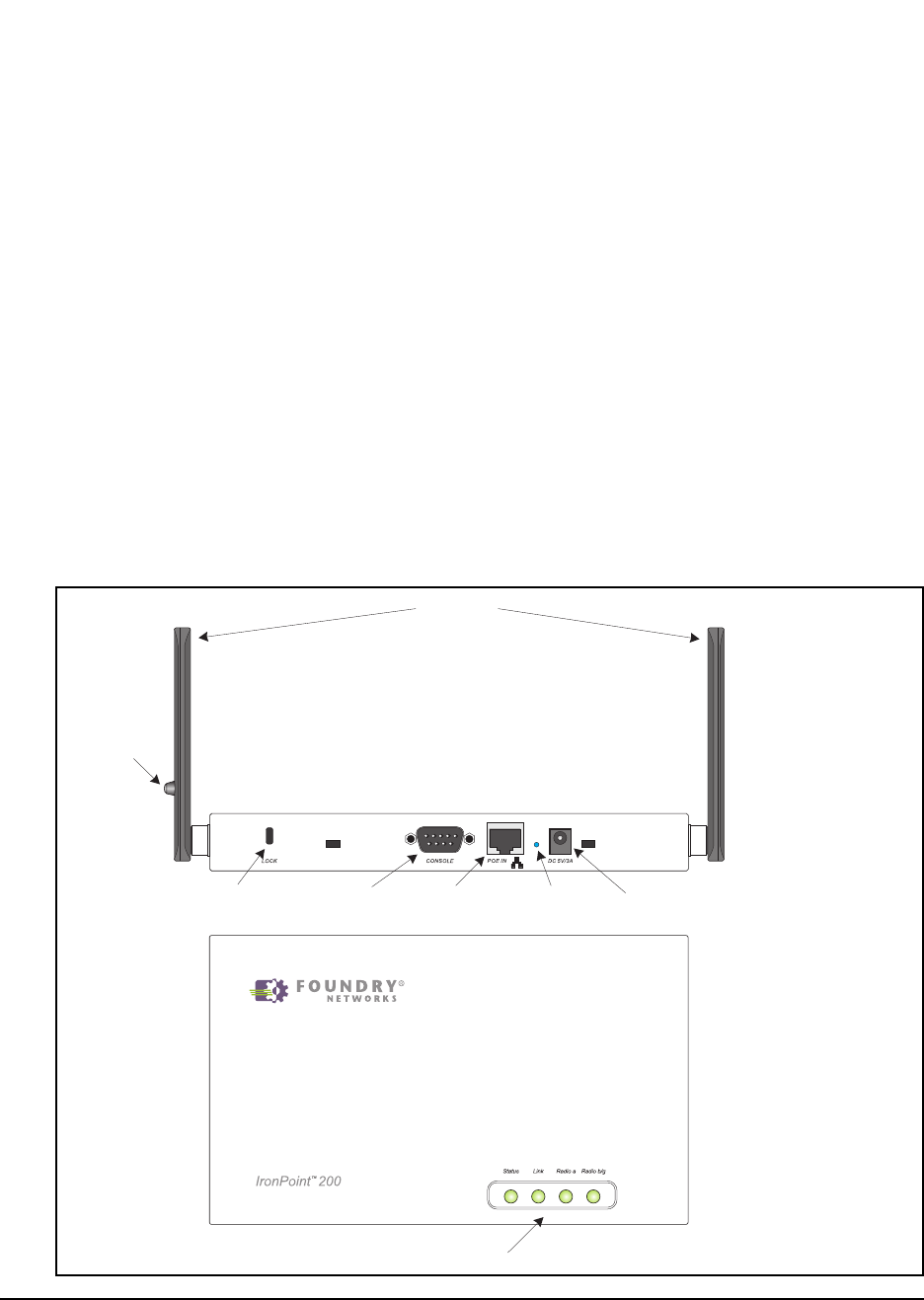
Figure 2-1. Top and Front Panels
Front Panel
Top Panel
Antennas
Status LEDs
5V DC
Power Socket
RJ-45
Connector
Console
Port
Reset
Button
Security
Lock
External
Antenna
Connector

Foundry IronPoint 200 Installation Guide
2-2 © 2003 Foundry Networks, Inc. April 2004
Radio Characteristics
The IEEE 802.11a/g standard uses a radio modulation technique known as Orthogonal Frequency
Division Multiplexing (OFDM), and a shared collision domain (CSMA/CA). It operates at the 5 GHz
Unlicensed National Information Infrastructure (UNII) band for connections to 802.11a clients, and at
2.4 GHz for connections to 802.11g clients.
IEEE 802.11g includes backward compatibility with the IEEE 802.11b standard. IEEE 802.11b also
operates at 2.4 GHz, but uses Direct Sequence Spread Spectrum (DSSS) modulation technology to
achieve a communication rate of up to 11 Mbps.
The access point also supports a 54 Mbps half-duplex connection to Ethernet networks for each
active channel (up to 108 Mbps in turbo mode on the 802.11a interface).
Management Options
The
IronPoint 200
contains LEDs for “at-a- glance” monitoring of wireless and network port status. It
also includes a built-in network management agent that allows the access point to be managed in-
band using SNMP, with a web browser, or remotely via Telnet. The access point provides an RS-232
DCE serial port (DB-9 connector) on the front panel for out-of-band management. A PC may be
connected to this port
for configuration and monitoring out-of band via a
straight-through serial cable.
(See “Console Port Pin Assignments” on page B-3 for wiring options.)
For a detailed description of the access point’s management features, refer to the Foundry
IronPoint 200 User Guide.

About the IronPoint 200
April 2004 © 2003 Foundry Networks, Inc. 2-3
Description of Hardware
Ethernet Port
The access point has one 10BASE-T/100BASE-TX RJ-45 Ethernet port that can be attached directly
to a 10BASE-T/100BASE-TX wired network. The wired network must conform to the IEEE 802.3 or
802.3u specifications.
The Ethernet port uses an MDI (i.e., internal straight-through) pin configuration. You can therefore
use straight-through twisted-pair cable to connect this port to most network interconnection devices,
such as a switch or router, that provide MDI-X ports. However, when connecting the access point to
a workstation or other device that does not have MDI-X ports, you must use a crossover twisted-pair
cable.
The access point appears as an Ethernet node and performs a bridging function by moving packets
from the wired network to remote workstations in the wireless infrastructure.
Note: The RJ-45 port supports Power over Ethernet (PoE) based on the IEEE 802.3af standard.
Refer to the description for the “Power Connector” for information on supplying power to the access
point’s network port from a network device, such as a switch, that provides Power over Ethernet
(PoE).
Antennas
The access point includes two integrated antennas for wireless communications. The signal
transmitted from both antennas is identical, but only the best signal received on one of the antennas
is used. The antennas transmit the outgoing signal as a toroidal sphere (doughnut shaped), so the
antennas should be adjusted to different angles to provide better coverage. For further information,
see “Installing the IronPoint Access Point” on page 4-1.
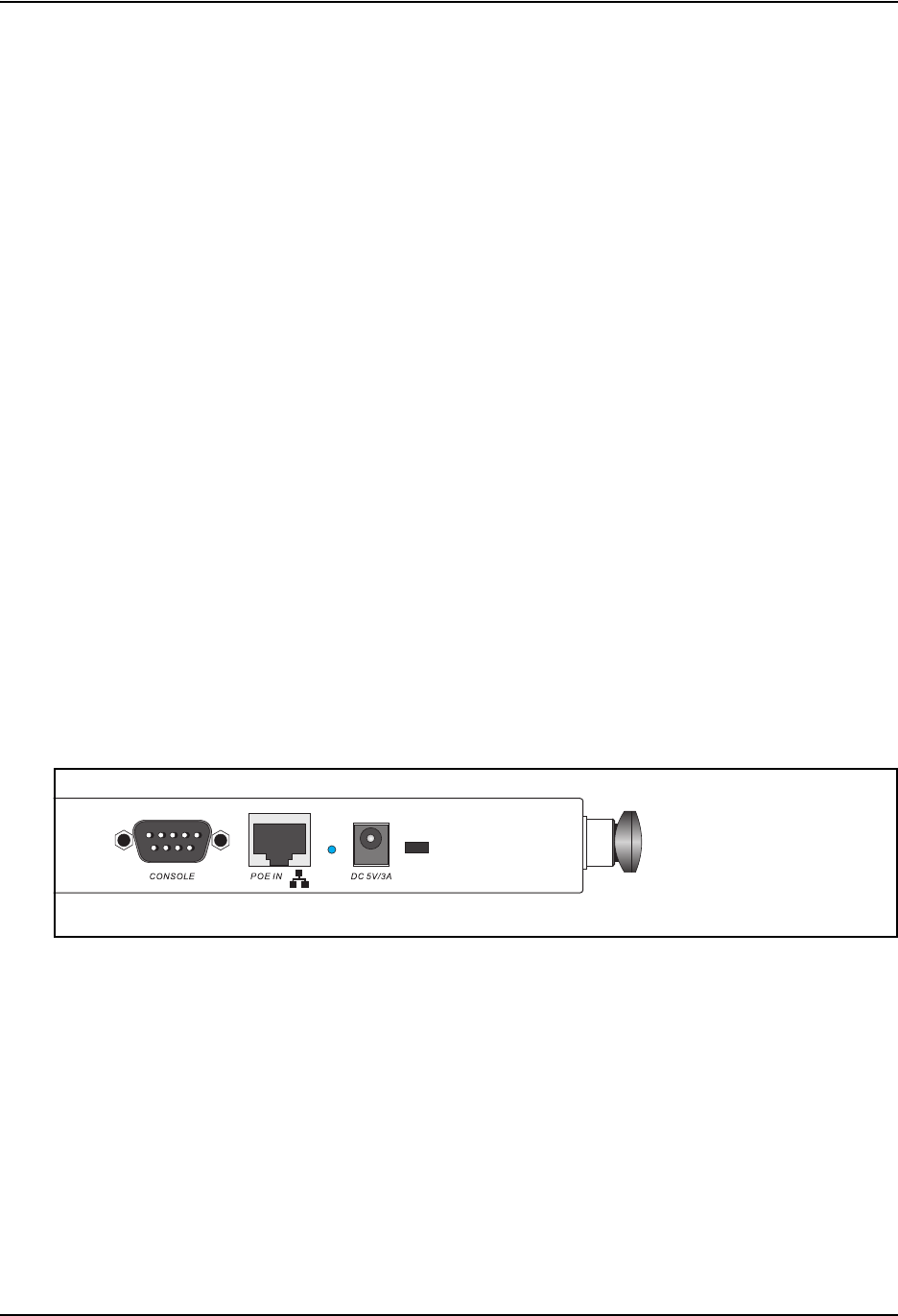
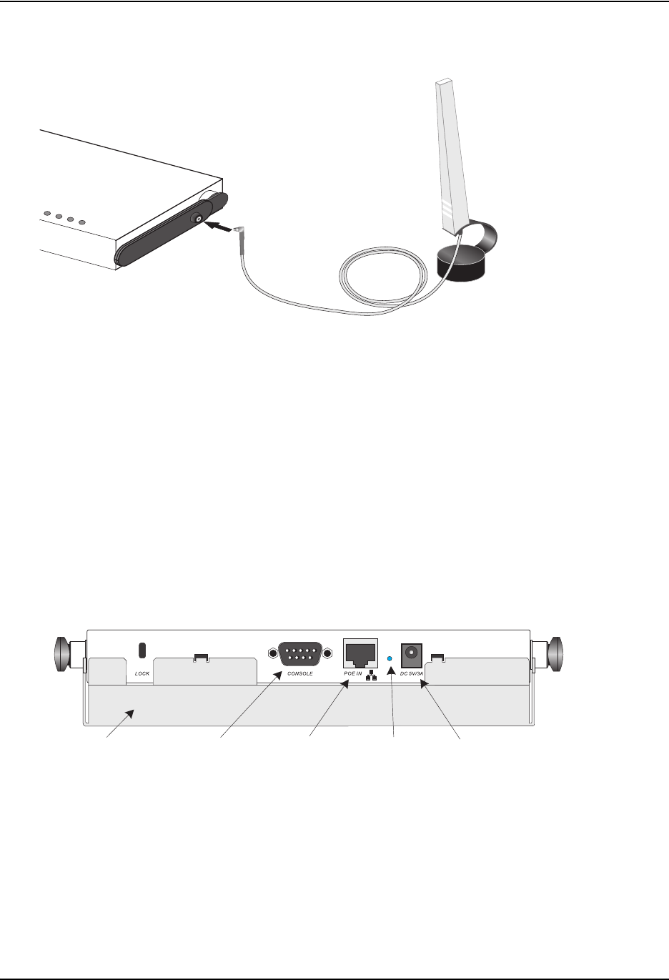
Optional External Antenna
To extend the the access point’s radio coverage area, an optional 2.4 GHz high-gain antenna (for
802.11b and/or 802.11g clients) can be attached to a connection socket that is provided on one
antenna. When an external antenna is connected, the access point automatically disables the two
integrated antennas and uses only the external antenna.
Figure 2-2. An Example of an Optional External Antenna

Foundry IronPoint 200 Installation Guide
2-4 © 2003 Foundry Networks, Inc. April 2004
Status LEDs
The access point includes four status LED indicators, as described in the following figure and table.
Figure 2-3. Status LEDs
Status LEDs
LED Status Description
Status On Indicates that power is being supplied to the access point.
Flashing Indicates -
• the access point is running its self-test
• the access point is loading its software program
Flashing (Prolonged) Indicates a system error.
Link On Indicates a valid 10/100 Mbps Ethernet cable link.
Flashing Indicates that the access point is transmitting or receiving data on
the attached 10/100 Mbps Ethernet LAN. The flashing rate is
proportional to network activity.
Radio a On Indicates a valid 802.11a wireless link.
Very Slow Flashing The access point is searching for 802.11a network association.
Slow Flashing Indicates that one or more 802.11a wireless clients are associated
with the access point, but there is no activity.
Fast Flashing Indicates that the access point is transmitting or receiving data
through 802.11a wireless links. The flashing rate is proportional to
network activity.
Radio b/g On Indicates a valid 802.11g or 802.11b wireless link.
Very Slow Flashing The access point is searching for 802.11b or 802.11g network
association.
Slow Flashing Indicates that one or more 802.11b or 802.11g wireless clients are
associated with the access point, but there is no activity.
Fast Flashing Indicates that the access point is transmitting or receiving data
through 802.11g or 802.11b wireless links. The flashing rate is
proportional to network activity.
About the IronPoint 200
April 2004 © 2003 Foundry Networks, Inc. 2-5
Security Slot
The access point includes a Kensington security slot on the rear panel. You can prevent
unauthorized removal of the access point by wrapping the Kensington security cable (not provided)
around an unmovable object, inserting the lock into the slot, and turning the key.
Console Port
This port is used to connect a console device to the access point through a serial cable. This
connection is described under “Console Port Pin Assignments” on page B-3. The console device can
be a PC or workstation running a VT-100 terminal emulator, or a VT-100 terminal.
Reset Button
This button is used to reset the access point or restore the factory default configuration. If you hold
down the button for less than 5 seconds, the access point will perform a hardware reset. If you hold
down the button for 5 seconds or more, any configuration changes you may have made are removed,
and the factory default configuration is restored to the access point.
Power Connector
The access point does not have a power switch. It is powered on when connected to the AC power
adapter, and the power adapter is connected to a power source. The access point automatically
adjusts to any voltage between 100-240 volts at 50 or 60 Hz. No voltage range settings are required.
The access point may also receive Power over Ethernet (PoE) from a switch or other network device
that supplies power over the network cable based on the IEEE 802.3af standard.
Note that if the access point is connected to a PoE source device and also connected to a local
power source through the AC power adapter, PoE will be disabled.
Figure 2-4. Power Supply Receptacle

Foundry IronPoint 200 Installation Guide
2-6 © 2003 Foundry Networks, Inc. April 2004
Features and Benefits
Connectivity
◆54 Mbps wireless interface supports up to 64 mobile users
◆Local network connection via 10/100 Mbps Ethernet port
◆IEEE 802.11a, 802.11b, and 802.11g compliant on the wireless interfaces
◆IEEE 802.3 and IEEE 802.3u compliant on the Ethernet interface
◆Ethernet port supports Power over Ethernet based on the IEEE 802.3af standard
◆Provides seamless roaming within the IEEE 802.11a, 802.11b, and 802.11g WLAN environment
◆Scans all available channels and selects the best channel for each client based on the signal-to-
noise ratio
◆Optional high-gain 2.4 GHz external antenna can be attached to extend the service area
◆Advanced security through 64/128/152-bit Wired Equivalent Protection (WEP) encryption, IEEE
802.1x port authentication, Wi-Fi Protected Access (WPA), SSID broadcast disable, remote
authentication via RADIUS server, and MAC address filtering
◆Auto-negotiation enables the Ethernet port to automatically select the optimum communication
mode (half or full duplex) if this feature is supported by the attached device; otherwise the port
can be configured manually
Management
◆“At-a-glance” LEDs for easy troubleshooting
◆Network management agent:
• Supports Telnet, SNMP and web-based interface
• Supports out-of-band RS-232 console port (VT100)

April 2004 © 2003 Foundry Networks, Inc. 3-1
Chapter 3
Network Planning
Network Topologies
The wireless solution supports a stand-alone wireless network configuration as well as an integrated
configuration with 10/100 Mbps Ethernet LANs.
Wireless network cards, adapters, and access points can be configured as:
•Ad hoc for departmental, SOHO, or enterprise LANs
•Infrastructure for wireless LANs
•Infrastructure wireless LAN for roaming wireless PCs
The 802.11b and 802.11g frequency band which operates at 2.4 GHz can easily encounter
interference from other 2.4 GHz devices, such as other 802.11b or g wireless devices, cordless
phones and microwave ovens. If you experience poor wireless LAN performance, try the following
measures:
•Limit any possible sources of radio interference within the service area
•Increase the distance between neighboring access points
•Decrease the signal strength of neighboring access points
•Increase the channel separation of neighboring access points (e.g., up to 3 channels of
separation for 802.11b, up to 4 channels for 802.11a, or up to 5 channels for 802.11g)
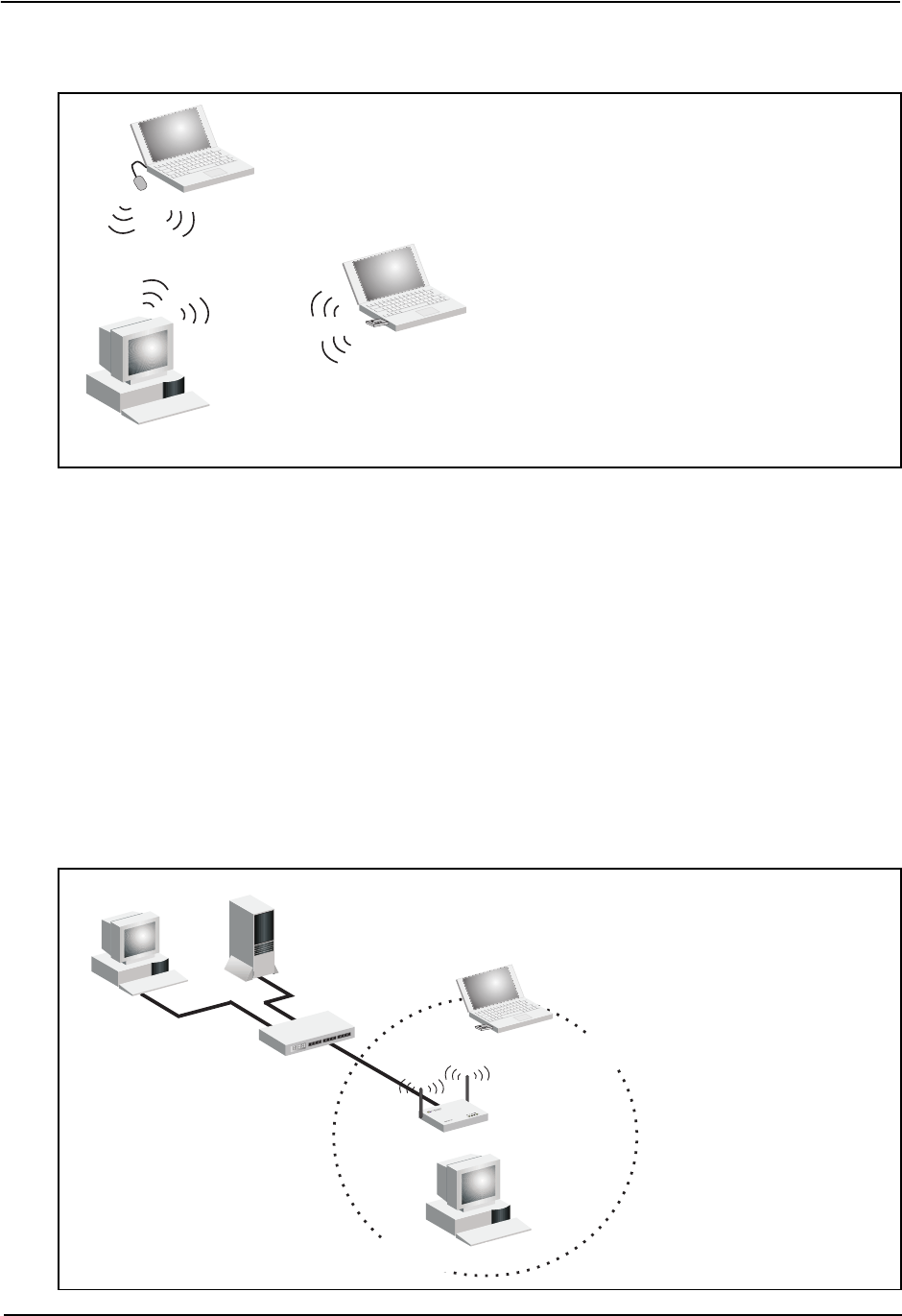
Ad Hoc Wireless LAN (no AP or Bridge)
An ad hoc wireless LAN consists of a group of computers, each equipped with a wireless adapter,
connected via radio signals as an independent wireless LAN. Computers in a specific ad hoc
wireless LAN must therefore be configured to the same radio channel.
Foundry IronPoint 200 Installation Guide
3-2 © 2003 Foundry Networks, Inc. April 2004
Figure 3-1. Ad Hoc Wireless LAN
Infrastructure Wireless LAN
The access point is designed to provide access to a wired LAN for wireless workstations. An
integrated wired/wireless LAN is called an Infrastructure configuration. A Basic Service Set (BSS)
consists of a group of wireless PC users and an access point that is directly connected to the wired
LAN. Each wireless PC in this BSS can talk to any computer in its wireless group via a radio link, or
access other computers or network resources in the wired LAN infrastructure via the access point.
The infrastructure configuration not only extends the accessibility of wireless PCs to the wired LAN,
but also increases the effective wireless transmission range for wireless PCs by passing their signal
through one or more access points.
A wireless infrastructure can be used for access to a central database, or for a connection between
mobile workers, as shown in the following figure.
Figure 3-2. Infrastructure Wireless LAN
Ad Hoc Wireless LAN
Notebook with
Wireless USB Adapter
Notebook with
Wireless PC Card
PC with Wireless
PCI Adapter
Server
Switch
Desktop PC
Access Point
PC with Wireless
PCI Adapter
Notebook with Wireless
PC Card Adapter
Wired LAN Extension to
Wireless Clients
Network Planning
April 2004 © 2003 Foundry Networks, Inc. 3-3
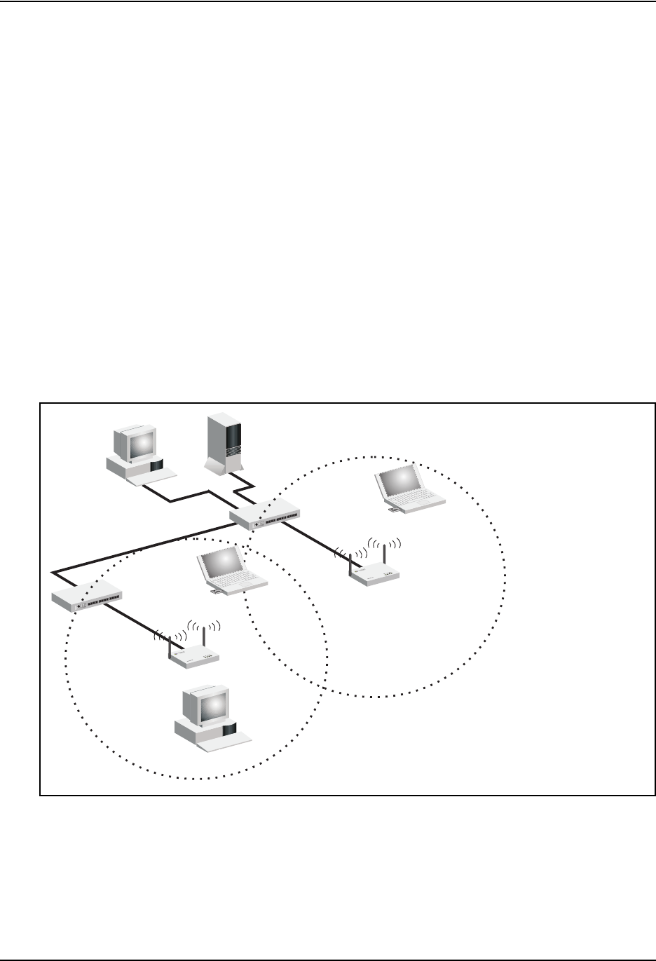
Infrastructure Wireless LAN for Roaming Wireless PCs
The Basic Service Set (BSS) defines the communications domain for each access point and its
associated wireless clients. The BSS ID is a 48-bit binary number based on the access point’s
wireless MAC address, and is set automatically and transparently as clients associate with the
access point. The BSS ID is used in frames sent between the access point and its clients to identify
traffic in the service area.
The BSS ID is only set by the access point, never by its clients. The clients only need to set the
Service Set Identifier (SSID) that identifies the service set provided by one or more access points.
The SSID can be manually configured by the clients, can be detected in an access point’s beacon, or
can be obtained by querying for the identity of the nearest access point. For clients that do not need
to roam, set the SSID for the wireless card to that used by the access point to which you want to
connect.
A wireless infrastructure can also support roaming for mobile workers. More than one access point
can be configured to create an Extended Service Set (ESS). By placing the access points so that a
continuous coverage area is created, wireless users within this ESS can roam freely. All wireless
network cards and access points within a specific ESS must be configured with the same SSID.
Figure 3-3. Wireless LAN Roaming
<BSS2>
Seamless Roaming
<ESS>
<BSS1>
Server
Switch
Desktop PC
Access Point
PC with Wireless
PCI Adapter
Notebook with Wireless
PC Card Adapter
Notebook with Wireless
PC Card Adapter
Access Point
Switch

Foundry IronPoint 200 Installation Guide
3-4 © 2003 Foundry Networks, Inc. April 2004

April 2004 © 2003 Foundry Networks, Inc. 4-1
Chapter 4
Installing the IronPoint 200 Access Point
This section presents procedures for installing the IronPoint access point.
Unpacking the IronPoint Access Point
Unpack the IronPoint access point and make sure the following components are included in the box:
• One IronPoint 200 access point
• One External Power supply and power cable
• RS-232 console cable
• IronPoint 200 access point mounting bracket with lock clamp
• 2 fasteners
• CD-ROM containing the IronPoint Access Point manuals, drivers, and utility
• 4 adhesive feet
Installing the IronPoint Access Point
Select a location to install the IronPoint access point. The best location is at the center of your
wireless coverage area, within the line of sight of all wireless devices. The access point can be
placed on a horizontal surface or mounted on the wall, with or without the mounting bracket. It can
also be mounted on a suspended ceiling.
Note: For safety reasons, make sure ventilation holes on the access point are positioned
horizontally, not vertically. Allow at least 1 inch (2.54 centimeters) clearance around the ventilation
holes for proper ventilation.
Placing the Access Point on a Desktop or Shelf
Do the following if you want to mount the access point on a horizontal surface, such as a desktop or
shelf:
1. Attach the four adhesive feet to the bottom panel of the access point (Figure 4-1).

Foundry IronPoint 200 Installation Guide
4-2 © 2003 Foundry Networks, Inc. April 2004
Figure 4-1. Attaching Feet to the Access Point
2. Set the access point on its four rubber feet on the desktop, shelf, or flat surface, making sure
there is enough clearance around the ventilation holes for proper air flow. For safety reasons,
make sure ventilation holes on the access point are positioned horizontally, not vertically.
3. For best coverage, position the antennas at 90 degrees from each other: one antenna up and
one horizontal to the other.
Attaching the Access Point to a Wall without the Mounting Bracket
Do the following if you want to mount the access point on a wall without the mounting bracket:
1. Use the template in Figure 4-2 to mark the holes for the two slotted key mounting screws on the
wall.
2. Install the two screws for the slotted key mounting holes on the wall.
3. Insert the slotted mounting holes on the back of the access point over the screws.
4. Slide the access point across the screws so the screws move into the narrow part of the slotted
mounting holes. For safety reasons, make sure ventilation holes on the access point are
positioned horizontally, not vertically.
5. For best coverage, position the antennae at 90 degrees from each other: one antenna up and
one horizontal to the other.

Installing the IronPoint 200 Access Point
April 2004 © 2003 Foundry Networks, Inc. 4-3
Figure 4-2. Template for Mounting the IronPoint 200 Access Point to a Wall
For slotted key mounting hole For slotted key mounting hole
Top or unit

Foundry IronPoint 200 Installation Guide
4-4 © 2003 Foundry Networks, Inc. April 2004
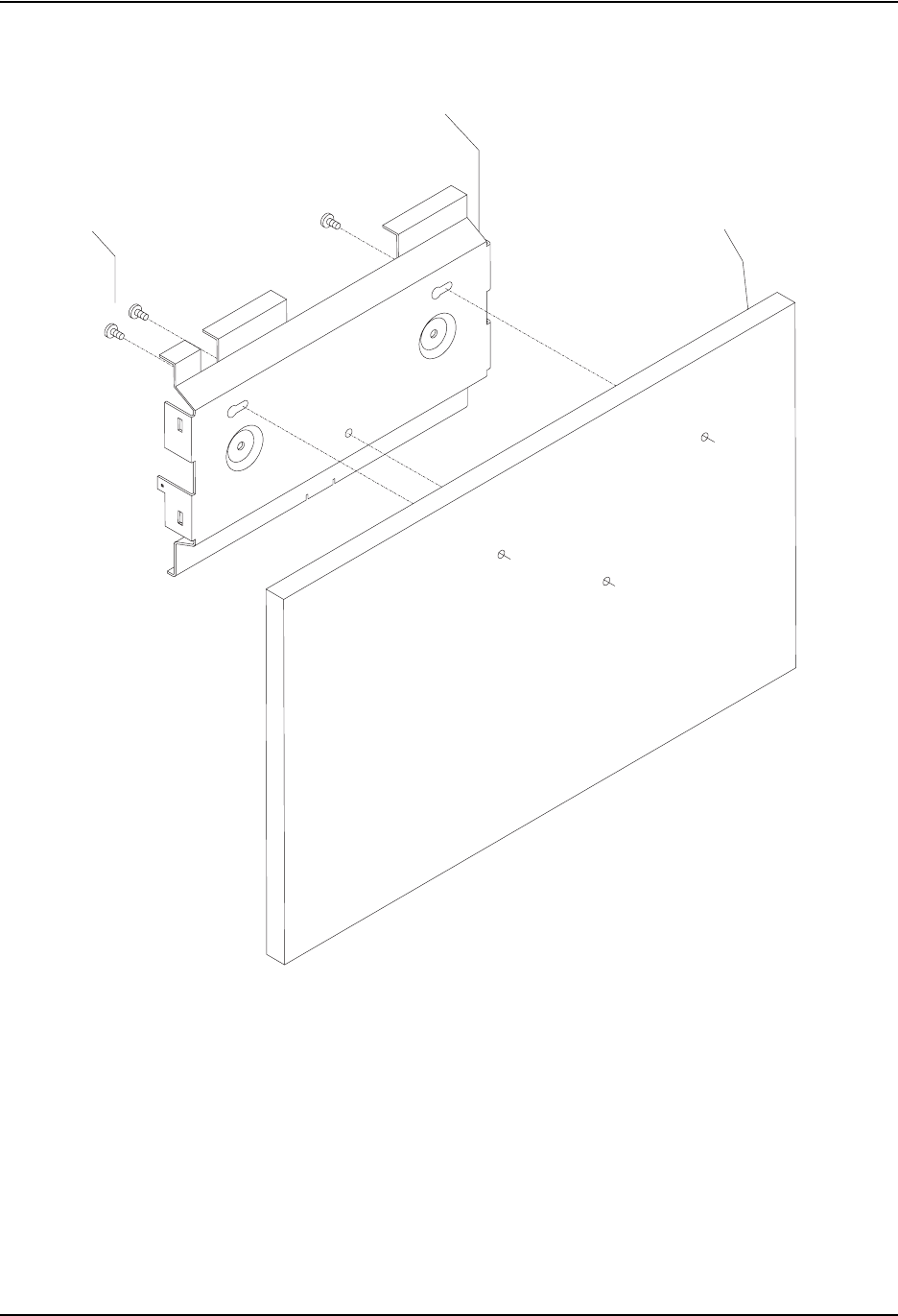
Attaching the Access Point to a Wall Using the Mounting Bracket
Do the following to attach the access point to the wall using the mounting bracket:
1. Use the template in Figure 4-2 to mark the holes for the mounting screws on the wall.
2. Install the mounting screws for the two slotted key mounting holes on the wall, but leave
approximately 1/4 inch of clearance between the wall and the screw head.
3. Install the mounting bracket on the wall by aligning the slotted key mounting holes on the
mounting bracket with the screws on the wall (Figure 4-3).
4. Slide the mounting bracket across the screws to move the screws into the narrow part of the
mounting holes.
5. Tighten the screws to secure the mounting bracket in place.
6. Install the mounting screw at the bottom of the bracket.
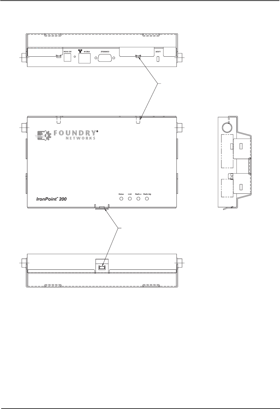
7. Install the access point into the mounting bracket by aligning the two rear tabs on the mounting
brackets with the two rear rectangular holes on the access point (Figure 4-4). For safety reasons,
make sure ventilation holes on the access point are positioned horizontally, not vertically.
8. Press the access point into the mounting bracket until it snaps into place. The clip locks the
access point in place.
9. For best coverage, position the antennae at 90 degrees from each other: one antenna up and
one horizontal to the other.
Installing the IronPoint 200 Access Point
April 2004 © 2003 Foundry Networks, Inc. 4-5
Figure 4-3. Attaching the Mounting Bracket to a Wall
Mounting Bracket
Wall
No. 6 Screws
Foundry IronPoint 200 Installation Guide
4-6 © 2003 Foundry Networks, Inc. April 2004
Figure 4-4. Installing the Access Point in the Mounting Bracket
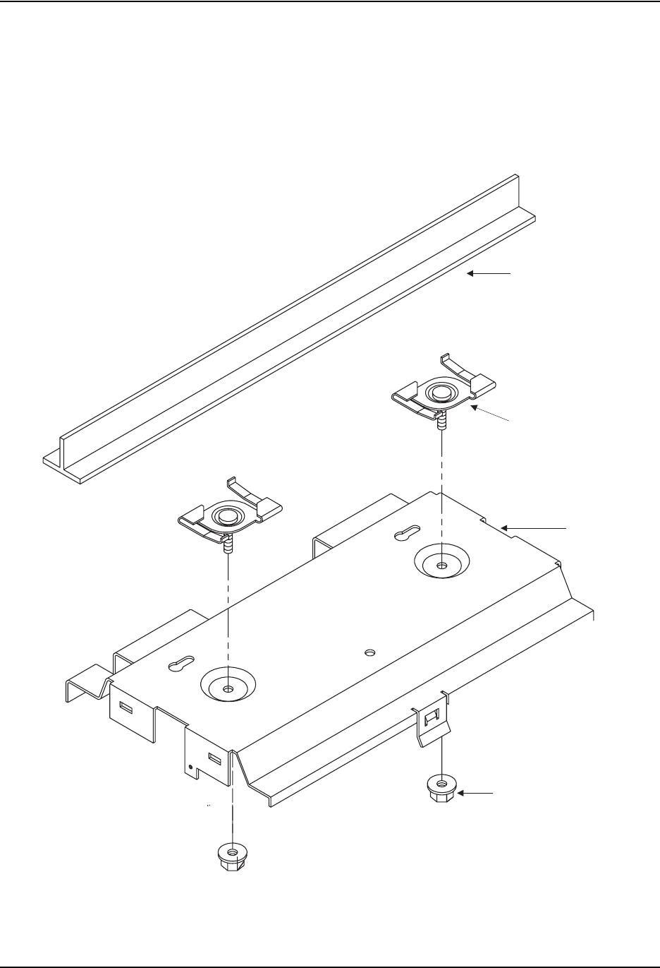
Attaching the Access Point to a Suspended Ceiling
To mount the access point to a suspended ceiling (Figure 4-5), do the following:
1. Obtain the two fasteners and remove the their lock nuts.
2. Choose a location on the ceiling where the access point will be installed and position the
fasteners around the suspended ceiling T-rail.
3. Align the ceiling mounting holes on the mounting bracket with the fasteners.
4. Install the two lock nuts on the mounting bracket to fasten the mounting bracket to the T-rail.
5. Install the access point into the mounting bracket by aligning the two rear tabs on the mounting
brackets with the two rear rectangular holes on the access point (Figure 4-4).
Allign tabs to
rectangular openings
and slide unit back.
AP unit will snap-into
rectangular opening and
lock in place.
Installing the IronPoint 200 Access Point
April 2004 © 2003 Foundry Networks, Inc. 4-7
6. Press the access point against the bracket until it snaps into place. The clip locks the access
point in place. Install the 2-56 screws on the sides of the access point.
7. For best coverage, position the antennae at 90 degrees from each other: one antenna up and
one horizontal to the other.
Figure 4-5. Attaching the Bracket to a Suspended Ceiling
Lock Nut
Mounting Bracket
Fastener
Suspended Ceiling T-rail
Foundry IronPoint 200 Installation Guide
4-8 © 2003 Foundry Networks, Inc. April 2004
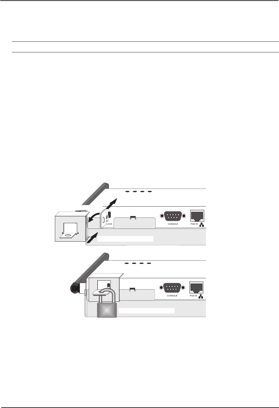
Locking the Access Point
You can lock the access point on the mounting bracket by doing the following:
Note: The access point comes with a lock clamp, but you must purchase your own lock and key.
1. Complete the steps in the previous sections to attach the access point to a wall or suspended
ceiling using the mounting bracket. Make sure the access point is installed in the mounting
bracket.
2. Put the lock clamp key into the top of the access point's lock hole.
3. Turn the lock clamp key to the horizontal position (about 90 degree turn). (The key only turns only
in one direction.)
4. Push the lock key down to the bottom of the lock groove towards the mounting bracket.
5. Line up the lock clamp with the lock clamp key.
6. Insert a lock into the hole of the locking clamp and lock it into place.
Figure 4-6. Locking the Access Point
Installing the External Antenna
You can install an external antenna to extend the access point's coverage area. If you install the
external antenna while live sessions are on the access point, those sessions will be terminated.
To install the external antenna:
1. Remove the rubber grommet from the access point's right integrated antenna to expose the
external antenna connector.
1. Insert Key
2. Tur n Key
3. Slide clamp over Key
4. Secure with pad lock
Installing the IronPoint 200 Access Point
April 2004 © 2003 Foundry Networks, Inc. 4-9
Figure 4-7. Connecting the External Antenna
2. Insert the external antenna's MC Card connector (otherwise known as a Lucent convertor) to the
external antenna connector.
3. Set the Antenna Mode for the 802.11b/g radio interface to "external" using the CLI, Web
interface, or IronView Network Management.
4. Enable the radio interface using the CLI, Web interface, or IronView Network Management.
Powering Up the Access Point
Prepare the access point for power up by doing the following:
1. Connect the RS-232 console cable to the access point’s console port.
Figure 4-8. Connecting to the Console Port
2. Connect the other end of the RS-232 console cable to your PC's serial port.
3. On your PC console application configure the following communication parameters:
• 9600 bits per second
• 8 data bits
•No parity
• 1 stop bits
5V DC
Power Socket
RJ-45
Connector
Console
Port
Reset
Button
Wall-Mount
Bracket

Foundry IronPoint 200 Installation Guide
4-10 © 2003 Foundry Networks, Inc. April 2004
• No Flow Control
4. Connect the power adapter cable to the 5V DC power socket on the access point and the other
end of the cable to a power source.
CAUTION:Use ONLY the power adapter supplied with this access point. Otherwise, the product
may be damaged.
Adding the IronPoint Access Point to the Network
The access point’s country code and TCP/IP address information must be configured before an
access point can be managed or added to a network. Setting the correct country code allows the
access point to use the necessary channels and frequencies assigned to your country's wireless
frequency regulations. This must be done prior to using the access point for the first time as the
802.11a and 802.11b/g radios are turned off initially until the country code has been set.
Note: Country regulations for wireless products differ from country to country. The access points
may be shipped with the country code already preset, as required by the country, or set to the
default setting of "99". If your country code is pre-set (for example, for United States, Canada,
Japan, and New Zealand), you are prohibited from changing this setting. If country code on your
access point is set to "99", then you may set the country code, but you can set it only to the country
in which the access point is to be used.
It is very important to follow these instructions carefully. Selection of the wrong country code for your
device could result in the device operating outside of authorized frequency/power allocations and
lead to possible legal action by the regulatory authority in your country
Although Foundry has attempted to provide accurate information in these materials, Foundry
assumes no legal responsibility for the accuracy or completeness of the information. Please note
that Foundry's product information does not constitute or contain any guarantee, warranty or legally
binding representation, unless expressly identified as such in aduly signed writing.
Foundry's IronPoint access point uses TCP/IP to communicate with the management consoles. By
using TCP/IP, you can place access points anywhere in the enterprise and manage them from a
single central location. IronPoint access points do not need to be physically connected to any
wireless LAN switch to be managed.
Do the following to configure the access point’s country code and IP address:
1. Once the access point completely powers up, enter the default administrator user name and
password on your PC console as follows to gain access to the CLI:
Username: admin
Password: admin
2. Set the correct country code with the country command. For example, to set the country code to
the United Kingdom, enter:
IronPoint# country gb

Installing the IronPoint 200 Access Point
April 2004 © 2003 Foundry Networks, Inc. 4-11
Syntax: country <country_code>
You can view a list of supported country codes by entering the following command:
IronPoint# country ?
The list of supported countries and their codes is displayed:
WORD Country code: AL-ALBANIA, DZ-ALGERIA, AR-ARGENTINA, AM-ARMENIA,
AU-AUSTRALIA, AT-AUSTRIA, AZ-AZERBAIJAN, BH-BAHRAIN, BY-BELARUS,
BE-BELGIUM, BZ-BELIZE, BO-BOLVIA, BR-BRAZIL, BN-BRUNEI_DARUSSALAM,
BG-BULGARIA, CA-CANADA, CL-CHILE, CN-CHINA, CO-COLOMBIA, CR-COSTA_RICA,
HR-CROATIA, CY-CYPRUS, CZ-CZECH_REPUBLIC, DK-DENMARK,
DO-DOMINICAN_REPUBLIC, EC-ECUADOR, EG-EGYPT, EE-ESTONIA, FI-FINLAND,
FR-FRANCE, GE-GEORGIA, DE-GERMANY, GR-GREECE, GT-GUATEMALA,
HK-HONG_KONG, HU-HUNGARY, IS-ICELAND, IN-INDIA, ID-INDONESIA, IR-IRAN,
IE-IRELAND, IL-ISRAEL, IT-ITALY, JP-JAPAN, JO-JORDAN, KZ-KAZAKHSTAN,
KP-NORTH KOREA, KR-KOREA_REPUBLIC, KW-KUWAIT, LV-LATVIA, LB-LEBANON,
LI-LIECHTENSTEIN, LT-LITHUANIA, LU-LUXEMBOURG, MO-MACAU, MK-MACEDONIA,
MY-MALAYSIA, MX-MEXICO, MC-MONACO, MA-MOROCCO, NL-NETHERLANDS,
NZ-NEW_ZEALAND, NO-NORWAY, OM-OMAN, PK-PAKISTAN, PA-PANAMA, PE-PERU,
PH-PHILIPPINES, PL-POLAND, PT-PORTUGAL, PR-PUERTO_RICO, QA-QATAR,
RO-ROMANIA, RU-RUSSIA, SA-SAUDI_ARABIA, SG-SINGAPORE,
SK-SLOVAK_REPUBLIC, SI-SLOVENIA, ZA-SOUTH_AFRICA, ES-SPAIN, SE-SWEDEN,
CH-SWITZERLAND, SY-SYRIA, TW-TAIWAN, TH-THAILAND, TR-TURKEY,
UA-UKRAINE, AE-UNITED_ARAB_EMIRATES, GB-UNITED_KINGDOM,
US-UNITED_STATES, UY-URUGUAY, VE-VENEZUELA, VN-VIETNAM
3. Configure the TCP/IP address. The default IP address for the access point is 169.254.1.1 with a
255.255.0.0 subnet mask and a default gateway of 169.254.1.254. To change the access point's
IP address, for example, to 192.168.1.10 with a 24-bit subnet mask and a default gateway of
192.168.1.254, enter:
IronPoint# configure
IronPoint(config)# interface ethernet
IronPoint(if-ethernet)# ip address 192.168.1.10 255.255.255.0 192.168.1.254
IronPoint(if-ethernet)# end
IronPoint #
Syntax: interface ethernet
ip address <ip-address> <subnet-mask> <default-gateway>
4. Confirm the Country Code and TCP/IP settings with the show system command. Do not
proceed unless the information displayed is correct. For example, to confirm the country code of
the United Kingdom and the TCP/IP address of 192.168.8.10/24, enter:
IronPoint # show system
Syntax: show system
The command displays the following information:
IronPoint # show system
System Information
============================================================
Serial Number : SACC1200KA
System Up time : 0 days, 0 hours, 5 minutes, 25 seconds

Foundry IronPoint 200 Installation Guide
4-12 © 2003 Foundry Networks, Inc. April 2004
System Name : Foundry AP
System Location :
System Contact : Contact
System Country Code : GB - UNITED KINGDOM
MAC Address : 00-0C-DB-813-882
IP Address : 192.168.8.10
Subnet Mask : 255.255.255.0
Default Gateway : 192.168.8.254
VLAN State : DISABLED
Management VLAN ID(AP): 1
IAPP State : ENABLED
DHCP Client : DISABLED
HTTP Server : ENABLED
HTTP Server Port : 80
HTTPS Server : ENABLED
HTTPS Server Port : 443
Slot Status : Dual band(a/g)
Software Version : 01.2.03.00Tw8
SSH Server : ENABLED
SSH Server Port : 22
Telnet Server : ENABLED
============================================================
5. Power down the access point.
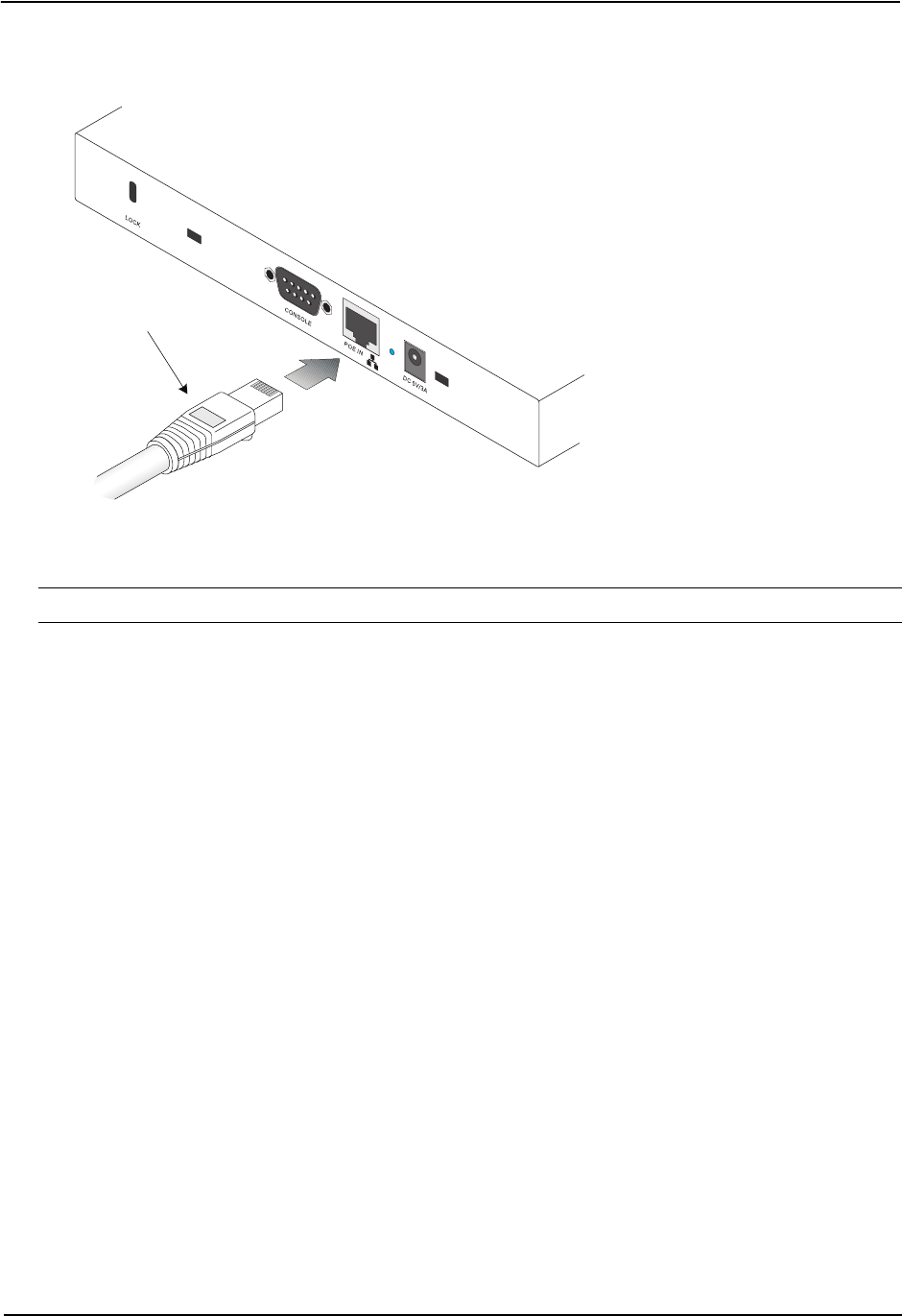
6. Connect one end of the Ethernet cable to the RJ-45 connector on the access point.
Note: The IronPoint access point also supports power over Ethernet (PoE) to obtain its power
from the RJ-45 port.
7. Connect the other end of the cable to the network subnet for which the access point was
programmed.
8. Power up the access point. It can now be managed using its command line interface ( CLI), Web
interface, or by the IronView Network Manager– IronPoint Edition.
Once the access point is set up with country code and IP address, other parameters can be defined
using one of the following methods:
• A PC running Internet Explorer version 5.0 (and above) Web browser to directly access an
individual IronPoint’s internal Web management interface.
• A PC running IronView® Network Manager to centrally manage the APs on the network.
• A Telnet client to directly access IronPoint’s command line interface (CLI).
Refer to the Foundry IronPoint 200 Quick Start Guide or the Foundry IronPoint 200 User Guide for
details.

April 2004 © 2003 Foundry Networks, Inc. 5-1
Chapter 5
Making a Network Connection
Connecting to a Network Device
The
IronPoint 200
is designed to connect a wired Ethernet network to wireless clients. It can be
connected to any Ethernet network device, such as a hub or switch.
Twisted-Pair Cable
The access point’s Ethernet port connection requires an unshielded twisted-pair (UTP) cable with
RJ-45 connectors at both ends. For 100BASE-TX connections, Category 5 or better cable is
required; for 10BASE-T, Category 3 or better cable can be used.
Cabling Guidelines
The RJ-45 port on the access point uses an MDI pin configuration. You must use straight-through
cable for network connections to hubs or switches that only have MDI-X ports, and crossover cable
for network connections to PCs, servers or other devices that only have MDI ports. However, if
connecting to a device port that supports auto-MDI/MDI-X operation, you can use either straight-
through or crossover cable.
See Appendix B for further information on cabling.
Caution: Do not plug a phone jack connector into the RJ-45 port. This will damage the access point.
Use only twisted-pair cables with RJ-45 connectors that conform to FCC standards.
Connecting to a Switch, Hub, PC, or Server
1. Attach one end of a twisted-pair cable segment to the network device’s RJ-45 connector.
Foundry IronPoint 200 Installation Guide
5-2 © 2003 Foundry Networks, Inc. April 2004
Figure 5-1. Connecting to a Network Device
2. Attach the other end of the cable segment to the Ethernet port on the access point.
Note: Make sure the twisted pair cable does not exceed 100 meters (328 ft) in length.
3. As the connection is made, the access point’s Link LED should light indicating a valid network
connection. If the Link LED fails to light, see Appendix A for troubleshooting information.
RJ-45 Connector

April 2004 © 2003 Foundry Networks, Inc. A-1
Appendix A
Troubleshooting
Diagnosing Access Point Indicators
Installation
Verify that all system components have been properly installed. If one or more components appear
to be malfunctioning (such as the power cord or network cabling), test them in an alternate
environment where you are sure that all the other components are functioning properly.
Console Access
If you cannot access the command line interface via a serial port connection, check the following
items before you contact Technical Support:
• Be sure you have set the terminal emulator program to VT100 compatible, 8 data bits, 1 stop bit,
no parity and 9600 bps.
• Check that the serial cable conforms to the pin-out connections provided in Appendix B.
Troubleshooting Chart
Symptom Action
Status LED is Off • External power supply may be disconnected. Check connections between
the AP, the power adapter, and the wall outlet.
• If using PoE, verify that AP’s RJ-45 port is attached to a PoE source device,
that the PoE source device is powered on, and that PoE power is enabled
on the port attached to the AP.
• Contact Technical Support.
Link LED is Off • Verify that the AP and attached device is powered on.
• Be sure the cable is plugged into both the AP and corresponding device.
• Verify that the proper cable type is used and its length does not exceed
specified limits.
• Check the cable connections for possible defects. Replace the cable if
necessary.

Foundry IronPoint 200 Installation Guide
A-2 © 2003 Foundry Networks, Inc. April 2004
In-Band Access
If the access point cannot be configured using the CLI via Telnet, a Web browser, or SNMP software,
check the following items before you contact Technical Support:
• Be sure to have configured the access point with a valid IP address, subnet mask and default
gateway.
• If VLANs are enabled on the access point, the management station should be configured to send
tagged frames with a VLAN ID that matches the access point’s native VLAN (default VLAN 1).
However, to manage the access point from a wireless client, the AP Management Filter should
be disabled.
• Check that you have a valid network connection to the access point and that the Ethernet port or
the wireless interface that you are using has not been disabled.
• If you are connecting to the access point through the wired Ethernet interface, check the network
cabling between the management station and the access point. If you are connecting to access
point from a wireless client, ensure that you have a valid connection to the access point.
• If you cannot connect using Telnet, you may have exceeded the maximum number of concurrent
Telnet sessions permitted (i.e, four sessions). Try connecting again at a later time.
Wireless Client Network Access
If wireless clients cannot access the network, check the following before you contact Technical
Support:
• Be sure the access point and the wireless clients are configured with the same Service Set ID
(SSID).
• If authentication or encryption are enabled, ensure that the wireless clients are properly
configured with the appropriate pre-shared key, authentication, or encryption keys. The wireless
client's NIC must have the necessary drivers to support the security and authentication methods
configured on the access point.
• If authentication is being performed through a RADIUS server, ensure that the clients are properly
configured on the RADIUS server.
• If authentication is being performed through IEEE 802.1x, be sure the wireless users have
installed and properly configured 802.1x client software.
• If MAC address filtering is enabled, be sure the client’s address is included in the local filtering
database or on the RADIUS server database.
• If the wireless clients are roaming between access points, make sure that all the access points
and wireless devices in the Extended Service Set (ESS) are configured to the same SSID, and
authentication method.
• Check the configuration matrix for the most commonly used authentication and encryption
combinations in the Quick Installation and Getting Started Guide to ensure that the access point
is correctly configured.

Troubleshooting
April 2004 © 2003 Foundry Networks, Inc. A-3
Lost Password
The only way to recover a lost password is by setting the access point to its default configuration.
Refer to the section “Reset the Access Point Default Settings” for instructions.
Reset the Access Point Default Settings
If all other recovery measures fail and the AP is still not functioning properly, take any of these steps:
• Reset the access point’s hardware using the console interface, web interface, or through a power
reset.
• Reset the access point to its default configuration by pressing the reset button on the back panel
for 5 seconds or more. Then use the default user name “admin” with the password “admin” to
access the management interface.

Foundry IronPoint 200 Installation Guide
A-4 © 2003 Foundry Networks, Inc. April 2004
Maximum Distance Tables
Important Notice
The maximum distances posted in the tables below are actual tested distance thresholds. However,
in any environment there are many variables, such as barrier composition and construction, and
local environmental interference, that may impact radio performance and cause you to experience
distance thresholds far lower than those specified.
Notes: 1. Line-of-Sight Environment: An environment with no interference or obstruction between
the access point and clients.
2. Office Environment: A typical office or home environment with floor to ceiling obstructions
between the access point and clients.
802.11a Wireless Distance Table
Environment Speed and Distance Ranges
72
Mbps
54
Mbps
48
Mbps
36
Mbps
24
Mbps
18
Mbps
12
Mbps
9
Mbps
6
Mbps
Line-of-Sight140 m
131 ft
85 m
279 ft
250 m
820 ft
310 m
1016 ft
400 m
1311 ft
445 m
1459 ft
455 m
1492 ft
465 m
1525 ft
510 m
1672 ft
Office220 m
66 ft
25 m
82 ft
35 m
115 ft
40 m
131 ft
45 m
148 ft
50 m
164 ft
55 m
180 ft
66 m
216 ft
70 m
230 ft
802.11b Wireless Distance Table
Speed and Distance Ranges
Environment 11 Mbps 5.5 Mbps 2 Mbps 1 Mbps
Line-of-Sight1300 m
984 ft
465 m
1525 ft
500 m
1639 ft
515 m
1689 ft
Office260 m
197 ft
70 m
230 ft
83 m
272 ft
85 m
279 ft
802.11g Wireless Distance Table
Environ-
ment
Speed and Distance Ranges
54
Mbps
48
Mbps
36
Mbps
24
Mbps
18
Mbps
12
Mbps
11
Mbps
9
Mbps
6
Mbps
5
Mbps
2
Mbps
1
Mbps
Line-of-
Sight1
82 m
269 ft
100 m
328 ft
300 m
984 ft
330 m
1082 ft
350 m
1148 ft
450 m
1475 ft
470 m
1541 ft
485 m
1590 ft
495 m
1623 ft
510 m
1672 ft
520 m
1705 ft
525 m
1722 ft
Office220 m
66 ft
25 m
82 ft
35 m
115 ft
43 m
141 ft
50 m
164 ft
57 m
187 ft
66 m
216 ft
71 m
233 ft
80 m
262 ft
85 m
279 ft
90 m
295 ft
93 m
305 ft

April 2004 © 2003 Foundry Networks, Inc. B-1
Appendix B
Cables
Specifications
Cable Types and Specifications
Cable Type Max. Length Connector
10BASE-T Cat. 3 or better 100-ohm UTP 100 m (328 ft) RJ-45
100BASE-TX Cat. 5 or better 100-ohm UTP 100 m (328 ft) RJ-45
Foundry IronPoint 200 Installation Guide
B-2 © 2003 Foundry Networks, Inc. April 2004
Twisted-Pair Cable and Pin Assignments
Caution: DO NOT plug a phone jack connector into any RJ-45 port. Use only twisted-pair cables
with RJ-45 connectors that conform with FCC standards.
For 100BASE-TX/10BASE-T connections, a twisted-pair cable must have two pairs of wires. Each
wire pair is identified by two different colors. For example, one wire might be green and the other,
green with white stripes. Also, an RJ-45 connector must be attached to both ends of the cable.
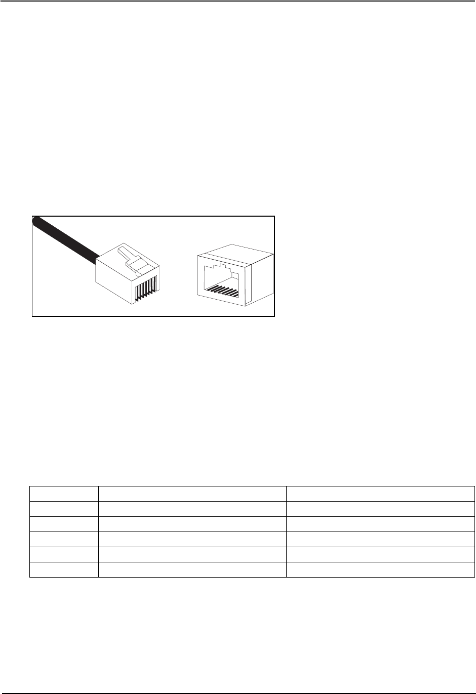
Caution: Each wire pair must be attached to the RJ-45 connectors in a specific orientation.
Figure B-1 illustrates how the pins on the RJ-45 connector are numbered. Be sure to hold the
connectors in the same orientation when attaching the wires to the pins.
Figure B-1. RJ-45 Connector Pin Numbers
100BASE-TX/10BASE-T Pin Assignments
Use unshielded twisted-pair (UTP) or shielded twisted-pair (STP) cable for RJ-45 connections:
100-ohm Category 3 or better cable for 10 Mbps connections, or 100-ohm Category 5 or better cable
for 100 Mbps connections. Also be sure
that the length of any twisted-pair connection does not
exceed 100 meters (328 feet).
The RJ-45 port on the access point is wired with MDI pinouts. This means that you must use
crossover cables for connections to PCs or servers, and straight-through cable for connections to
switches or hubs. However, when connecting to devices that support automatic MDI/MDI-X pinout
configuration, you can use either straight-through or crossover cable.
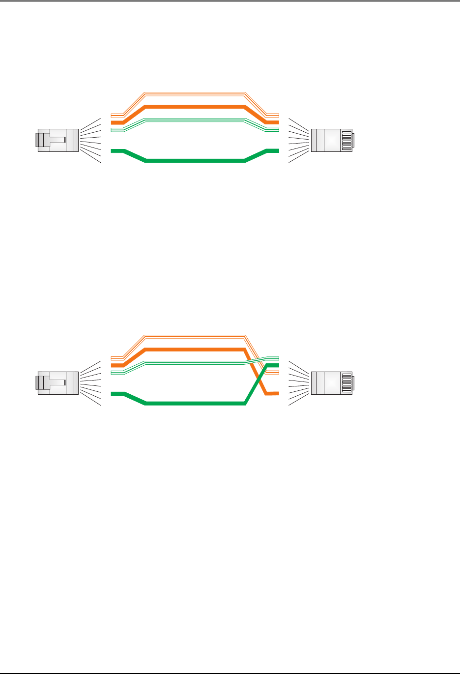
Straight-Through Wiring
Because the 10/100 Mbps port on the access point uses an MDI pin configuration, you must use
“straight-through” cable for network connections to hubs or switches that only have MDI-X ports.
However, if the device to which you are connecting supports auto-MDIX operation, you can use
either “straight-through” or “crossover” cable.
Pin MDI-X Signal Name MDI Signal Name
1 Receive Data plus (RD+) Transmit Data plus (TD+)
2 Receive Data minus (RD-) Transmit Data minus (TD-)
3 Transmit Data plus (TD+) Receive Data plus (RD+)
6 Transmit Data minus (TD-) Receive Data minus (RD-)
4, 5, 7, 8 Not used Not used
Note: The “+” and “-” signs represent the polarity of the wires that make up each wire pair.
1
881
Cables
April 2004 © 2003 Foundry Networks, Inc. B-3
Figure B-2. Straight-Through Wiring
Crossover Wiring
Because the 10/100 Mbps port on the access point uses an MDI pin configuration, you must use
“crossover” cable for network connections to PCs, servers or other end nodes that only have MDI
ports. However, if the device to which you are connecting supports auto-MDIX operation, you can
use either “straight-through” or “crossover” cable.
Figure B-3. Crossover Wiring
Console Port Pin Assignments
The DB-9 serial port on the IronPoint 200 is used to connect to the access point for out-of-band
management. The AP’s command-line interface can be accessed from a terminal or a PC running a
terminal emulation program.
Connect the console cable (included) to the RS-232 console port to access the command-line
interface. You can manage the access point using the console port, the web interface, or SNMP
management software. Refer to the Foundry IronPoint 200 User Guide for more information.
White/Orange Stripe
Orange
White/Green Stripe
Green
1
2
3
4
5
6
7
8
1
2
3
4
5
6
7
8
EIA
/
TIA 568B RJ-45 Wiring
S
tandard
10/100BASE-TX Straight-through Cable
End A End B
White/Orange Stripe
Orange
White/Green Stripe
Green
1
2
3
4
5
6
7
8
1
2
3
4
5
6
7
8
EIA/TIA 568B RJ-45 Wiring Standard
10/100BASE-TX Crossover Cable
End A End B

Foundry IronPoint 200 Installation Guide
B-4 © 2003 Foundry Networks, Inc. April 2004
The pin assignments used to connect to the console port are described in the following figure and
table.
Figure B-4. Serial Port (DB-9 DCE) Pin-Out
Wiring Map for Serial Cable
The serial port’s configuration requirements are as follows:
• Default Baud rate—9,600 bps
• Character Size—8 Characters
• Parity—None
• Stop bit—One
• Data bits—8
Signal (access point serial port) Pin Signal (management console port)
Unused 1 Unused
TXD (transmit data) 2 RXD (receive data)
RXD (receive data) 3 TXD (transmit data)
Unused 4 Unused
GND (ground) 5 GND (ground)
Unused 6 Unused
CTS (clear to send) 7 RTS (request to send)
RTS (request to send) 8 CTS (clear to send)
Unused 9 Unused
Note: The left hand column pin assignments are for the male DB-9 connector on the access point. Pin 2
(TXD or “transmit data”) must emerge on the management console’s end of the connection as RXD
(“receive data”). Pin 7 (CTS or “clear to send”) must emerge on the management console’s end of the
connection as RTS (“request to send”).
15
69

April 2004 © 2003 Foundry Networks, Inc. C-1
Appendix C
Specifications
General Specifications
Maximum Channels
802.11a:
US & Canada: 13 (normal mode), 5 (turbo mode)
Japan: 4 (normal mode), 1 (turbo mode)
ETSI: 11 channels (normal mode), 4 (turbo mode)
Taiwan: 8 (normal mode), 3 (turbo mode)
802.11g:
FCC/IC: 1-11
ETSI: 1-13
France: 10-13
MKK: 1-14
Taiwan: 1-11
Maximum Clients
64
Operating Range
See “Maximum Distance Tables” on page A-4.
Data Rate
802.11a:
Normal Mode: 6, 9, 12, 18, 24, 36, 48, 54 Mbps per channel
Turbo Mode: 12, 18, 24, 36, 48, 72, 96, 108 Mbps per channel
802.11g: 6, 9, 11, 12, 18, 24, 36, 48, 54 Mbps per channel
802.11b: 1, 2, 5.5, 11 Mbps per channel
Modulation Type
802.11a: BPSK, QPSK, 16-QAM, 64-QAM
802.11g: CCK, BPSK, QPSK, OFDM
802.11b: CCK, BPSK, QPSK
Network Configuration
Infrastructure
Operating Frequency
802.11a:
5.15 ~ 5.25 GHz (lower band) US/Canada, Japan
5.25 ~ 5.35 GHz (middle band) US/Canada

Foundry IronPoint 200 Installation Guide
C-2 © 2003 Foundry Networks, Inc. April 2004
5.725 ~ 5.825 GHz (upper band) US/Canada
5.50~ 5.70 GHz Europe
5.25 ~ 5.35 GHz (middle band) Taiwan
5.725 ~ 5.825 GHz (high band) Taiwan
802.11b/g:
2.4 ~ 2.4835 GHz (US, Canada, ETSI)
2.4 ~ 2.497 GHz (Japan)
2.400 ~ 2.4835 GHz (Taiwan)
Power supply
Input: 100-240 VAC, 50-60 Hz
Output: 5.1 VDC, 3 A
Power consumption: 13.2 watts
PoE (DC)
Input voltage: -48 VDC, 0.27 A, 12.96 watts
Note: Power can also be provided to the access point through the Ethernet port based on
IEEE 802.3af Power over Ethernet (PoE) specifications. When both PoE is provided and the adapter
is plugged in, PoE will be turned off.
Physical Size
21.83 x 13.73 x 3.27 cm (8.60 x 5.40 x 1.29 in)
Weight
0.80 kg (1.76 lbs)
LED Indicators
Status (power), Link (Ethernet link/activity), .Radio a
and Radio b/g (wireless link/activity)
Network Management
Web-browser, RS232 console, Telnet, SNMP
Temperature
Operating: 0 to 50 °C (32 to 122 °F)
Storage: 0 to 70 °C (32 to 158 °F)
Humidity
15% to 95% (non-condensing)
Compliances
FCC Class B (US)
ICES-003 (Canada)
RTTED 1999/5/EC
VCCI (Japan)
RCR STD-33A
Radio Signal Certification
FCC Part 15C 15.247, 15.207 (2.4 GHz)
FCC part 15E 15.407 (5 GHz)
RSS-210 (Canada)
EN 301.893, EN 300.328, EN 301.489-1, EN 301.489-17
MPT RCR std.33 (D33 1~13 Channel, T66 Channel 14)

Specifications
April 2004 © 2003 Foundry Networks, Inc. C-3
Safety
UL/cUL (UL 60950 & CSA 60950)
EN60950 (TÜV/GS), IEC60950 (CB)
LVD/EN 60950
Standards
IEEE 802.3 10BASE-T, IEEE 802.3u 100BASE-TX,
IEEE 802.11a, b, g
Sensitivity
IEEE 802.11a Sensitivity (GHz - dBm)
Modulation/Rates 5.15-5.250 5.25-5.350 5.50-5.700 5.725-5.825
BPSK (6 Mbps) -88 -88 -88 -88
BPSK (9 Mbps) -87 -87 -87 -87
QPSK (12 Mbps) -86 -86 -86 -86
QPSK (18 Mbps) -84 -84 -84 -84
16 QAM (24 Mbps) -82 -81 -81 -81
16 QAM (36 Mbps) -80 -79 -78 -78
64 QAM (48 Mbps) -73 -73 -73 -73
64QAM(54 Mbps) -70 -70 -69 -67
IEEE 802.11g
Data Rate Sensitivity (dBm)
6 Mbps -88
9 Mbps -87
12 Mbps -86
17 Mbps -85
24 Mbps -81
36 Mbps -77
48 Mbps -72
54 Mbps -70
IEEE 802.11b
Data Rate Sensitivity (dBm)
1 Mbps -93
2 Mbps -90
5.5 Mbps -90
11 Mbps -87

Foundry IronPoint 200 Installation Guide
C-4 © 2003 Foundry Networks, Inc. April 2004
Transmit Power
Note the following about the transmit power output specified in these tables:
• The output power is measured at the Hirose connector with an RMS (root mean square, or
average) power meter.
• Taiwan regulatory limits for maximum transmit power: 18 dBm for 802.11b, 16 dBm for 802.11g,
19 dBm for 802.11a
• The maximum transmit power is determined by both (1) the 10% packet error rate at 3 dB above
the 802.11a or 802.11b/g rate dependent sensitivity and (2) the 802.11a or 802.11b/g spectrum
mask limit.
• The maximum transmit power may be lowered by regulatory (FCC, ETSI, etc) EIRP (effective
isotropic radiated power) limits.
IEEE 802.11a Maximum Output Power (GHz - dBm)
Data Rate 5.15-5.250 5.25-5.350 5.50-5.700 5.725-5.825
6 Mbps 17 17 17 17
9 Mbps 17 17 17 17
12 Mbps 17 17 17 17
8 Mbps 17 17 17 17
24 Mbps 17 17 17 17
36 Mbps 17 17 17 17
48 Mbps 17 17 17 17
54 Mbps 12 17 17 16
IEEE 802.11g Maximum Output Power (GHz - dBm)
Data Rate 2.412 2.417~2.467 2.472
6 Mbps 20 20 18
9 Mbps 20 20 18
12 Mbps 20 20 18
18 Mbps 20 20 18
24 Mbps 20 20 18
36 Mbps 18 19 17
48 Mbps 17 16 15
54 Mbps 15 14 13
IEEE 802.11b Maximum Output Power (GHz - dBm)
Data Rate 2.412 2.417~2.467 2.472
1 Mbps 15 16 15
2 Mbps 15 16 15
5.5 Mbps 15 16 15
11 Mbps 15 16 15

Specifications
April 2004 © 2003 Foundry Networks, Inc. C-5
• The maximum transmit power may be lowered by regulatory (FCC, ETSI, etc) restricted limits
depending on the RF shielding of the platform in which the model is installed.

Foundry IronPoint 200 Installation Guide
C-6 © 2003 Foundry Networks, Inc. April 2004

April 2004 © 2003 Foundry Networks, Inc. Glossary-1
Glossary
10BASE-T
IEEE 802.3 specification for 10 Mbps Ethernet over two pairs of Category 3 or better UTP cable.
100BASE-TX
IEEE 802.3u specification for 100 Mbps Fast Ethernet over two pairs of Category 5 or better UTP
cable.
Access Point
An internetworking device that seamlessly connects wired and wireless networks. Access points
attached to a wired network, support the creation of multiple radio cells that enable roaming
throughout a facility.
Ad Hoc
A group of computers connected as an independent wireless network, without an access point.
Authentication
The process to verify the identity of a client requesting network access. IEEE 802.11 specifies two
forms of authentication: open system and shared key.
Backbone
The core infrastructure of a network. The portion of the network that transports information from one
central location to another central location where it is unloaded onto a local system.
Basic Service Set (BSS)
A set of 802.11-compliant stations and an access point that operate as a fully-connected wireless
network.
CSMA/CA
Carrier Sense Multiple Access with Collision Avoidance.
Dynamic Host Configuration Protocol (DHCP)
Provides a framework for passing configuration information to hosts on a TCP/IP network. DHCP is
based on the Bootstrap Protocol (BOOTP), adding the capability of automatic allocation of reusable
network addresses and additional configuration options.

Foundry IronPoint 200 Installation Guide
Glossary-2 © 2003 Foundry Networks, Inc. April 2004
Extended Service Set (ESS)
More than one wireless cell can be configured with the same Service Set Identifier to allow mobile
users can roam between different cells with the Extended Service Set.
Ethernet
A network communication system developed and standardized by DEC, Intel, and Xerox, using
baseband transmission, CSMA/CD access, logical bus topology, and coaxial cable. The successor
IEEE 802.3 standard provides for integration into the OSI model and extends the physical layer and
media with repeaters and implementations that operate on fiber, thin coax and twisted-pair cable.
Fast Ethernet
A 100 Mbps network communication system based on Ethernet and the CSMA/CD access method.
IEEE
Institute of Electrical and Electronic Engineers.
IEEE 802.11a
A wireless standard that supports high-speed communications in the 5 GHz band using Orthogonal
Frequency Division Multiplexing (OFDM). The standard supports data rates of 6, 12, 24, and 54
Mbps.
IEEE 802.11b
A wireless standard that supports wireless communications in the 2.4 GHz band using Direct
Sequence Spread Spectrum (DSSS). The standard provides for data rates of 1, 2, 5.5, and 11 Mbps.
IEEE 802.11g
A wireless standard that supports wireless communications in the 2.4 GHz band using supports
high-speed communications in the 5 GHz band using Orthogonal Frequency Division Multiplexing
(OFDM). The standard provides for data rates of 6, 9, 11, 12, 18, 24, 36, 48, 54 Mbps. IEEE 802.11g
is also backward compatible with IEEE 802.11b.
IEEE 802.1x
Port Authentication controls access to the switch ports by requiring users to first enter a user ID and
password for authentication.
IEEE 802.3
Defines carrier sense multiple access with collision detection (CSMA/CD) access method and
physical layer specifications.
IEEE 802.3u
Defines CSMA/CD access method and physical layer specifications for 100BASE-TX and
100BASE-FX Fast Ethernet.
Infrastructure
An integrated wireless and wired LAN is called an infrastructure configuration.
LED
Light emitting diode used for monitoring a device or network condition.

Glossary
April 2004 © 2003 Foundry Networks, Inc. Glossary-3
Local Area Network (LAN)
A group of interconnected computer and support devices.
MAC Address
The physical layer address used to uniquely identify network nodes.
Power over Ethernet (PoE)
A specification for providing both power and data to low-power network devices using a single
Category 5 Ethernet cable. PoE provides greater flexibility in the locating of access point’s and
network devices, and significantly decreased installation costs.
RADIUS
A logon authentication protocol that uses software running on a central server to control access to
the network.
RJ-45 Connector
A connector for twisted-pair wiring.
Roaming
A wireless LAN mobile user moves around an ESS and maintains a continuous connection to the
infrastructure network.
Service Set Identifier (SSID)
An identifier that is attached to packets sent over the wireless LAN and functions as a password for
joining a particular radio cell; i.e., Basic Service Set (BSS).
Simple Network Management Protocol (SNMP)
The application protocol in the Internet suite of protocols which offers network management
services.
Transmission Control Protocol/Internet Protocol (TCP/IP)
Protocol suite that includes TCP as the primary transport protocol, and IP as the network layer
protocol.
UTP
Unshielded twisted-pair cable.
Virtual LAN (VLAN)
A Virtual LAN is a collection of network nodes that share the same collision domain regardless of
their physical location or connection point in the network. A VLAN serves as a logical workgroup with
no physical barriers, and allows users to share information and resources as though located on the
same LAN.

Foundry IronPoint 200 Installation Guide
Glossary-4 © 2003 Foundry Networks, Inc. April 2004

April 2004 © 2003 Foundry Networks, Inc. Index-1
Index
Numerics
100BASE-TX ports 2-3
10BASE-T ports 2-3
A
ad hoc wireless LAN 3-1
air flow requirements 4-1
antennas, positioning 4-2
applications 3-1
ad hoc 3-1
infrastructure 3-2
wireless LAN roaming 3-3
B
Basic Service Set See BSS
bracket, wall mount 4-4
BSS 3-2
C
cable
crossover B-3
specifications B-1
straight-through B-2
channels, maximum C-1
clients, maximum C-1
console cable 2-2
console port 2-2, 2-5
pin assignments B-3
crossover cable B-3
CSMA/CA 2-2
D
data rate, options C-1
desktop mounting 4-1
distances, maximum A-4
E
Ethernet connection 5-1
F
features
management 2-6
switch 2-6
front panel of switch 2-1
I
IEEE 802.11a 2-2
indicators, LED 2-4
infrastructure wireless LANs 3-2
installation
connecting devices to the switch 5-1
desktop or shelf mounting 4-1
port connections 5-1
problems A-1
site requirements 4-1
wall mounting 4-2
L
LED indicators
problems A-1
location requirements 4-1
M
management
agent 2-2
features 2-6
out-of-band 2-2
SNMP 2-2

Foundry IronPoint 200 Installation Guide
Index-2 © 2003 Foundry Networks, Inc. April 2004
Web-based 2-2
maximum distances A-4
MDI, RJ-45 pin configuration 2-3
mounting the unit
on a desktop or shelf 4-1
on a wall 4-2
N
network
connections 5-1
topologies 3-1
network topologies 3-1
infrastructure 3-2
infrastructure for roaming 3-3
O
OFDM 2-2
operating frequency C-1
out-of-band management 2-2
P
password, support 1-1
pin assignments B-2
100BASE-TX/10BASE-T B-2
console port B-3
DB-9 B-3
PoE 2-3
specifications C-2
ports, connecting to 5-1
Power over Ethernet See PoE
power supply, specifications C-2
power, connecting to 4-10
problems, troubleshooting A-1
R
rear panel of switch 2-1
reset button 2-5
RJ-45 port connections 5-1
RJ-45 ports 2-3
roaming in wireless LANs 3-3
RS-232 port 2-2
S
serial cable 2-2
serial port 2-2
site location 4-1
SNMP agent 2-2
status LEDs 2-4
straight-through cable B-2
straight-through serial cable 2-2
support, technical 1-1
switching
introduction to 3-1
T
technical support 1-1
e-mail 1-2
telephone 1-2
Web 1-1
troubleshooting
in-band access A-2
switch indicators A-1
twisted-pair connections 5-1
W
wall mounting 4-2
wall mounting bracket 4-4
Web-based management 2-2
wireless LANs
ad hoc 3-1
infrastructure 3-2
roaming 3-3