Accton Technology ML6035 Metrolinq Outdoor 60GHz PTP + 5 GHz User Manual Metrolinq QSG R01 6pages 20151104
Accton Technology Corp Metrolinq Outdoor 60GHz PTP + 5 GHz Metrolinq QSG R01 6pages 20151104
Users Manual
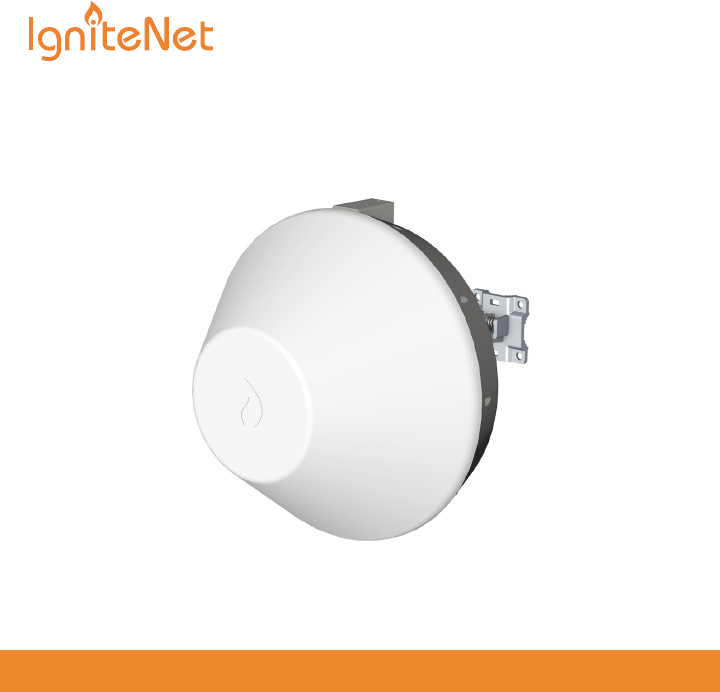
Welcome to MetroLinqTM
Interference-Free Gigabit Wireless
ignitenet.com

Unboxing
After opening the box, you will find…
• MetroLinqTM
• Bracket Kit
• POE Power Supply
• Power Cable
Tools/Items Required
• 13 mm Socket Wrench
• Flat-Head Screwdriver
• Ethernet Cables
• (Optional) Alignment Scope ICC-SCOPE-9x50
ignitenet.com2
For helpful training and user-case information, please go to ignitenet.com/support
ignitenet.com3
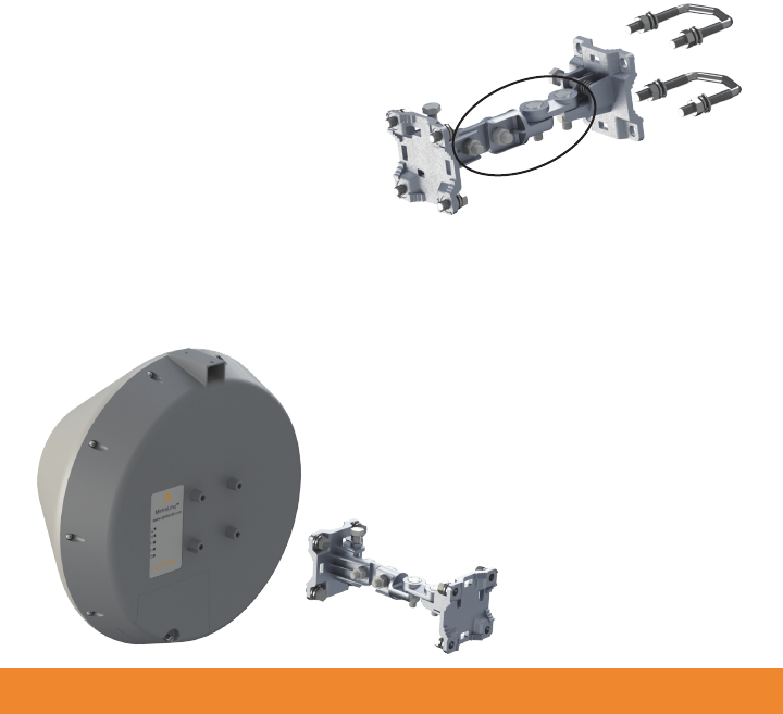
Assembly
The MetroLinq™ bracket is designed for
wall and pole mounting (25mm - 75mm
pole diameter). Choose what is best for
your location and select hardware
accordingly.
1. Ensure all four position-locking bolts are
tight before installing.
2. Install the bracket onto MetroLinq™
using four M8 bolts, lock washers, and
flat washers.
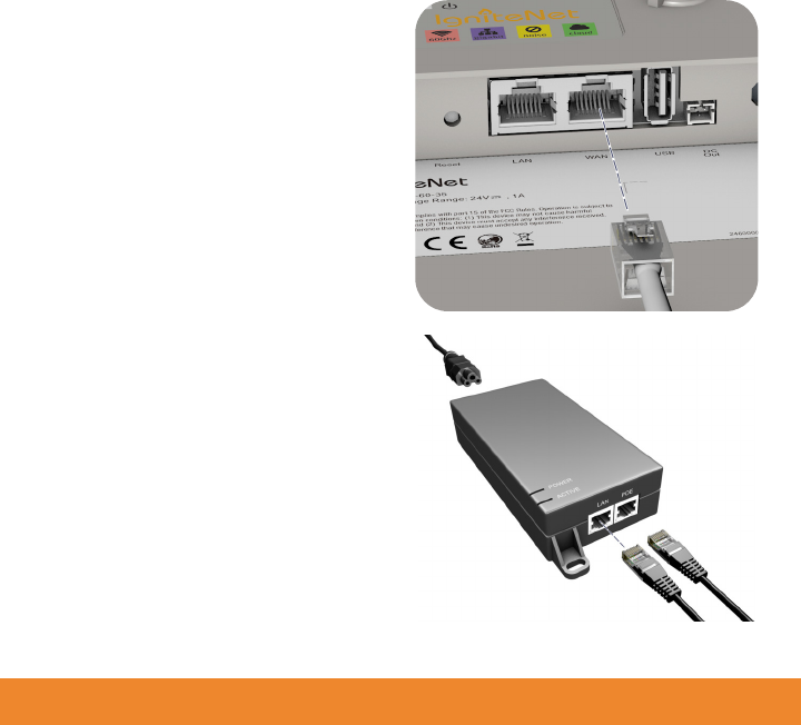
Power Up
1. Connect an Ethernet cable from the
MetroLinq™ WAN port (right-side
RJ-45) to the POE port on the power
supply.
2. Connect Ethernet cable from the
“LAN” port on the power supply
to your LAN device.
3. Connect the power cord to a nearby
AC power source.
ignitenet.com4
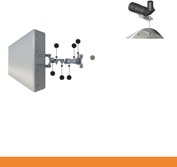
Alignment
IgniteNet strongly recommends using the ICC-SCOPE-9x50
Alignment Scope for alignment. To install, place the scope
on top of the MetroLinq™ housing and secure it with its
thumb screw.
ignitenet.com5
Note: Do not adjust bolts A
and B without first loosening
1 and 4 respectively.
!
1. Loosen coarse adjustment bolts 2 and 3 and set initial alignment. Don’tworry,
you don’t have to be too accurate yet. After you have set the coarse
alignment, tighten bolts 2 and 3.
2. Loosen the horizontal fine-tune adjustment bolt 4. Use fine-tune bolt "B" to
optimize the horizontal position. Re-tighten bolt 4.
3. Loosen the vertical fine-tune adjustment bolt 1. Use fine-tune bolt "A" to
optimize the vertical position. Re-tighten bolt 1.
4. Initial alignment should be based on optical or visual alignment. After you
achieve this, repeat steps 2 and 3 while watching the 60 GHz ignal strength
LED. Optimize position to the LED indicator.
5. Ensure all bolts are fully tightened, remove the alignment scope (if installed),
and enjoy Gigabit interference-free wireless.
B
14
A
23
ignitenet.com6
1. Loosen coarse adjustment bolts 2 and 3 and set initial alignment. Don’tworry,
you don’t have to be too accurate yet. After you have set the coarse
alignment, tighten bolts 2 and 3.
2. Loosen the horizontal fine-tune adjustment bolt 4. Use fine-tune bolt "B" to
optimize the horizontal position. Re-tighten bolt 4.
3. Loosen the vertical fine-tune adjustment bolt 1. Use fine-tune bolt "A" to
optimize the vertical position. Re-tighten bolt 1.
4. Initial alignment should be based on optical or visual alignment. After you
achieve this, repeat steps 2 and 3 while watching the 60 GHz ignal strength
LED. Optimize position to the LED indicator.
5. Ensure all bolts are fully tightened, remove the alignment scope (if installed),
and enjoy Gigabit interference-free wireless.
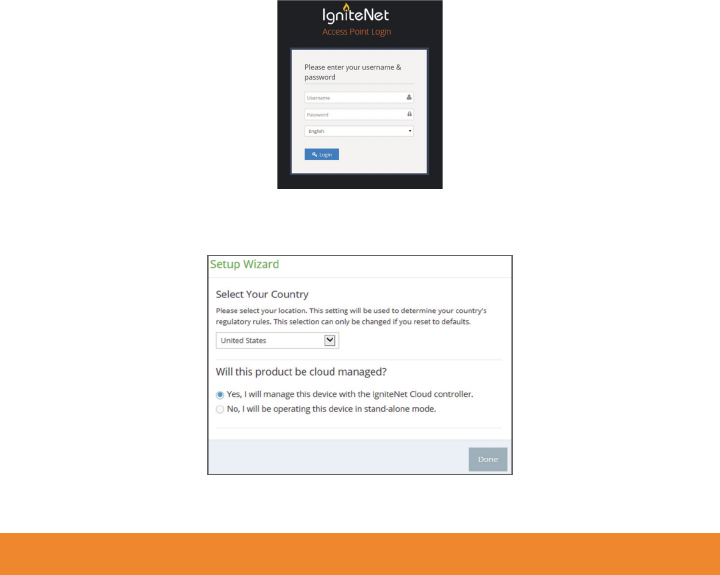
Software
1. To configure your MetroLinq, connect your computer to the LAN port on the
device and configure the IP subnet to match the default IP address of
192.168.1.20 Once configured, direct your web browser to 192.168.1.20 and
log in.
username: root
password: admin123
2. After you have logged in, follow the steps in the Setup Wizard to configure the
device for your network.
For more configuration details and training,
please go to ignitenet.com/support 150200001244A R01
FCC Statement:
Federal Communication Commission Interference Statement
This equipment has been tested and found to comply with the limits for a Class B digital device,
pursuant to Part 15 of the FCC Rules. These limits are designed to provide reasonable protection
against harmful interference in a residential installation. This equipment generates, uses and can
radiate radio frequency energy and, if not installed and used in accordance with the instructions, may
cause harmful interference to radio communications. However, there is no guarantee that interference
will not occur in a particular installation. If this equipment does cause harmful interference to radio or
television reception, which can be determined by turning the equipment off and on, the user is
encouraged to try to correct the interference by one of the following measures:
● Reorient or relocate the receiving antenna.
● Increase the separation between the equipment and receiver.
● Connect the equipment into an outlet on a circuit different from that to which the receiver is
connected.
● Consult the dealer or an experienced radio/TV technician for help.
FCC Caution: Any changes or modifications not expressly approved by the party responsible
for compliance could void the user’s authority to operate this equipment.
This device complies with Part 15 of the FCC Rules. Operation is subject to the following two
conditions: (1) This device may not cause harmful interference, and (2) this device must accept any
interference received, including interference that may cause undesired operation.
This device and it's antennas(s) must not be co-located or operating in conjunction with any other
antenna or transmitter except in accordance with FCC multi-transmitter product procedures.
IMPORTANT NOTE:
FCC Radiation Exposure Statement:
This equipment complies with FCC radiation exposure limits set forth for an uncontrolled environment.
This equipment should be installed and operated with minimum distance 250 cm between the radiator
& your body.

Antenna list:
Ant. Brand P/N Antenna
Type Connector
Antenna
Gain
(dBi)
Cable
Loss
(dB)
True
Gain
(dBi)
Remark
1 IgniteNet FS5-19N-120
Sector Ant.
(PATCH
ARRAY)
Type-N 19 1 18 External
(5GHz use)
Gain (dBi)
Ant. Brand P/N Antenna
Type Connector Band 1 Band 4 Remark
2 Accton 123400001084A Dish Ant. N/A 12.33 15.35
Internal
(5G&60G
use)
Professional installation instruction:
1. Installation personal
This product is designed for specific application and needs to be installed by a qualified personal who
has RF and related rule knowledge. The general user shall not attempt to install or change the setting.
2. Installation location
The product shall be installed at a location where the radiating antenna can be kept 250 cm from
nearby person in normal operation condition to meet regulatory RF exposure requirement.
3. External antenna
Use only the antennas which have been approved by the applicant. The non approved antenna(s)
may produce unwanted spurious or excessive RF transmitting power which may lead to the violation
of FCC limit and is prohibited.
4. Installation procedure
Please refer to user’s manual for the detail.
5. Warning
Please carefully select the installation position and make sure that the final output power does not
exceed the limit set force in relevant rules. The violation of the rule could lead to serious federal
penalty.