Accton Technology OAP2611A 802.11b/g Outdoor Access Point User Manual WI2
Accton Technology Corp 802.11b/g Outdoor Access Point WI2
UserManual.wiki
>
Accton Technology
>
OAP2611A User Manual
Users Manual
Navigation menu
Upload a User Manual
Namespaces
Wiki Guide
HTML
PDF
Info
Views
User Manual
Discussion / Help
Navigation
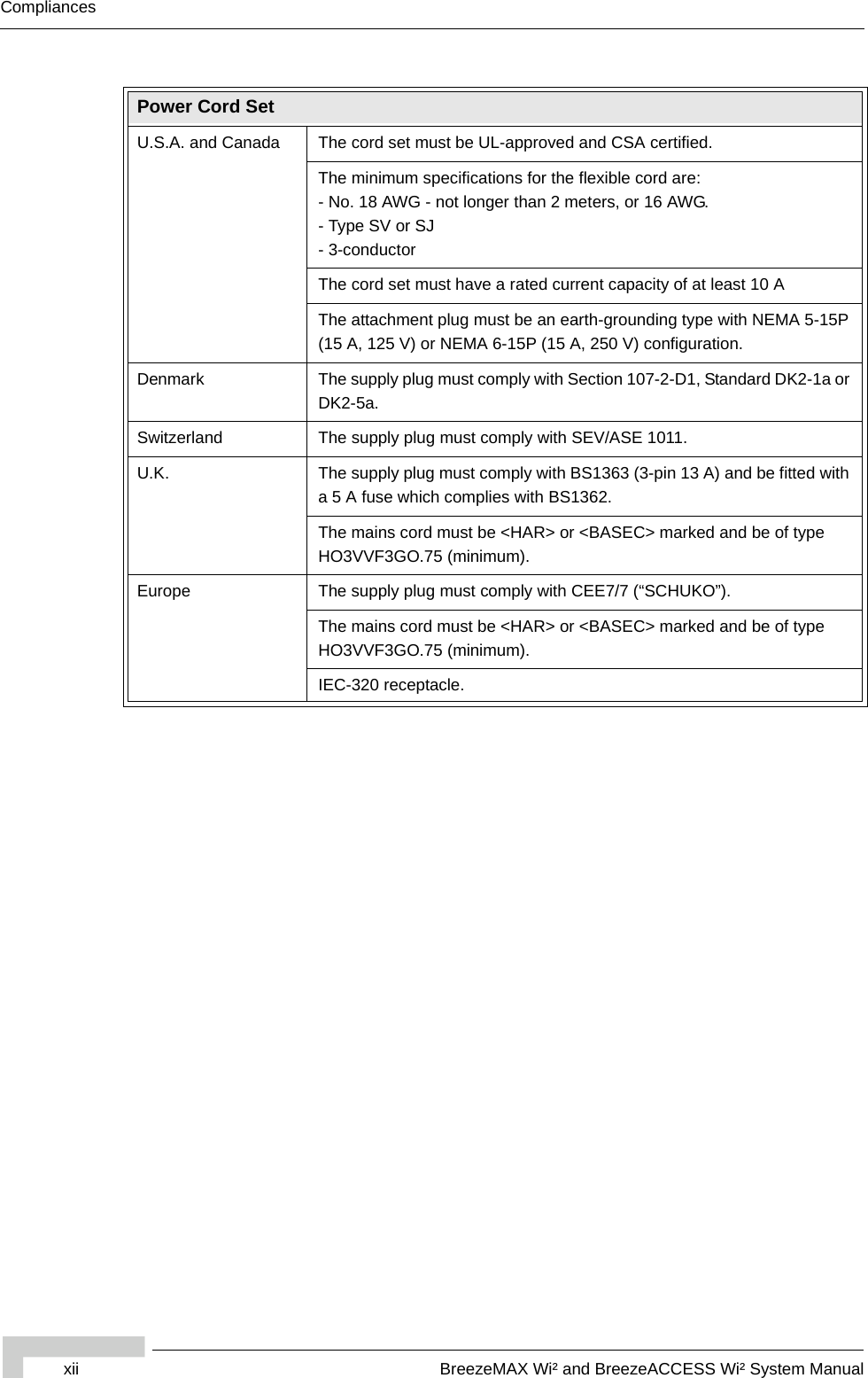
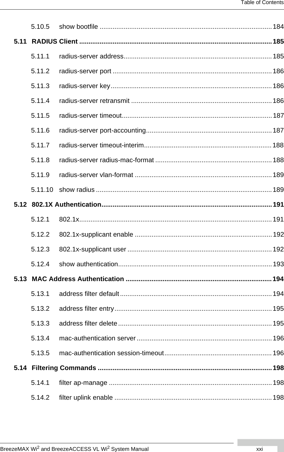

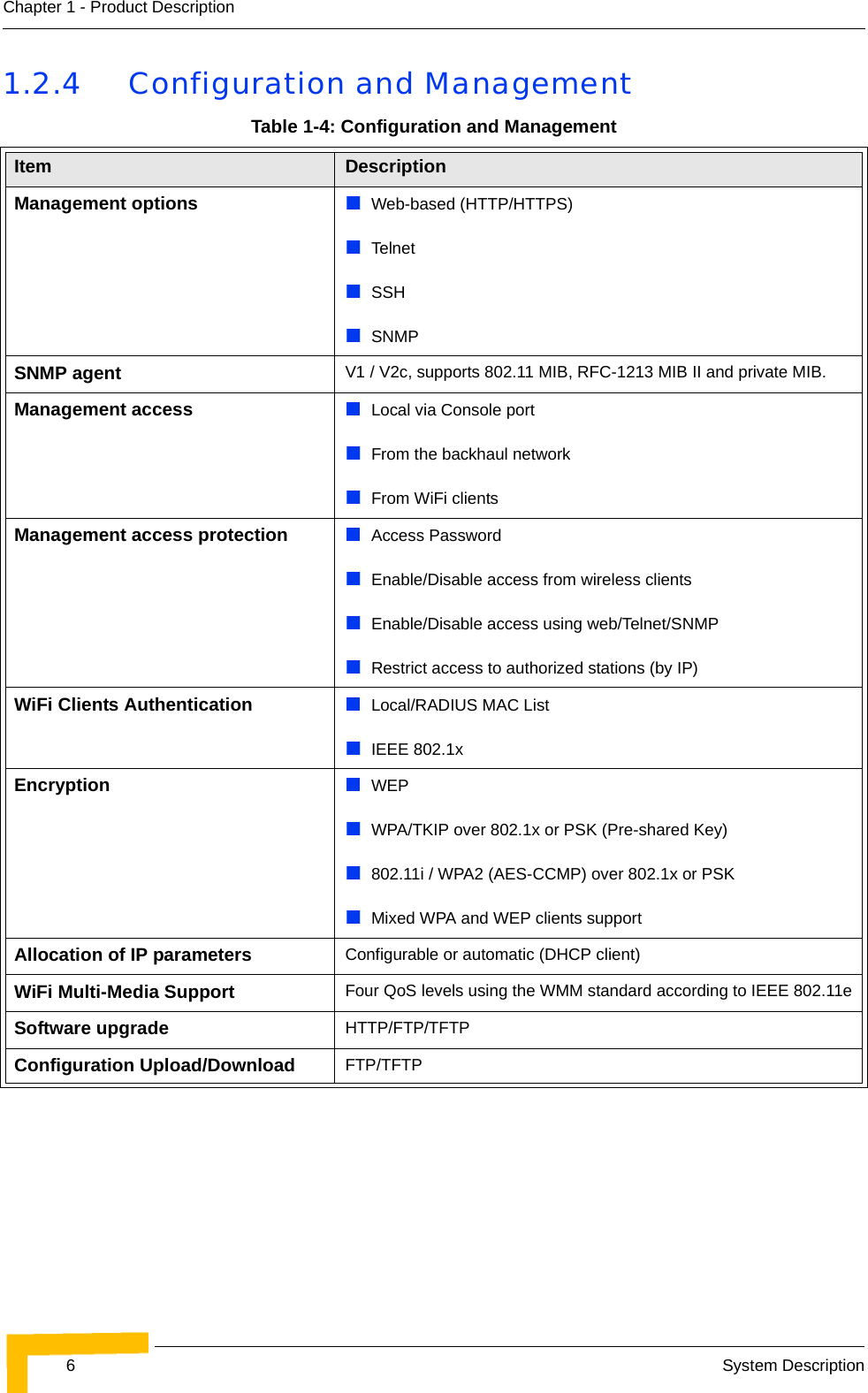

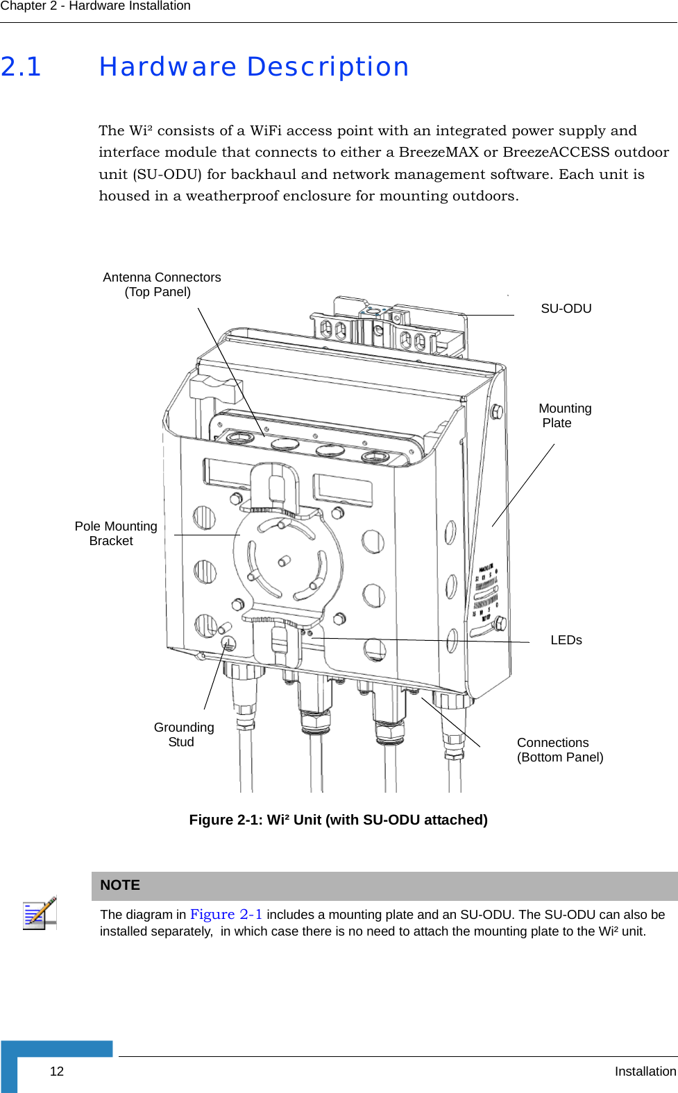
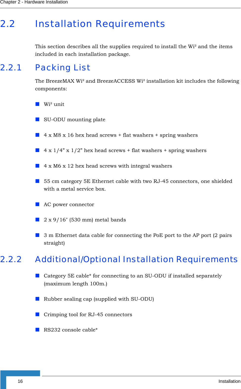
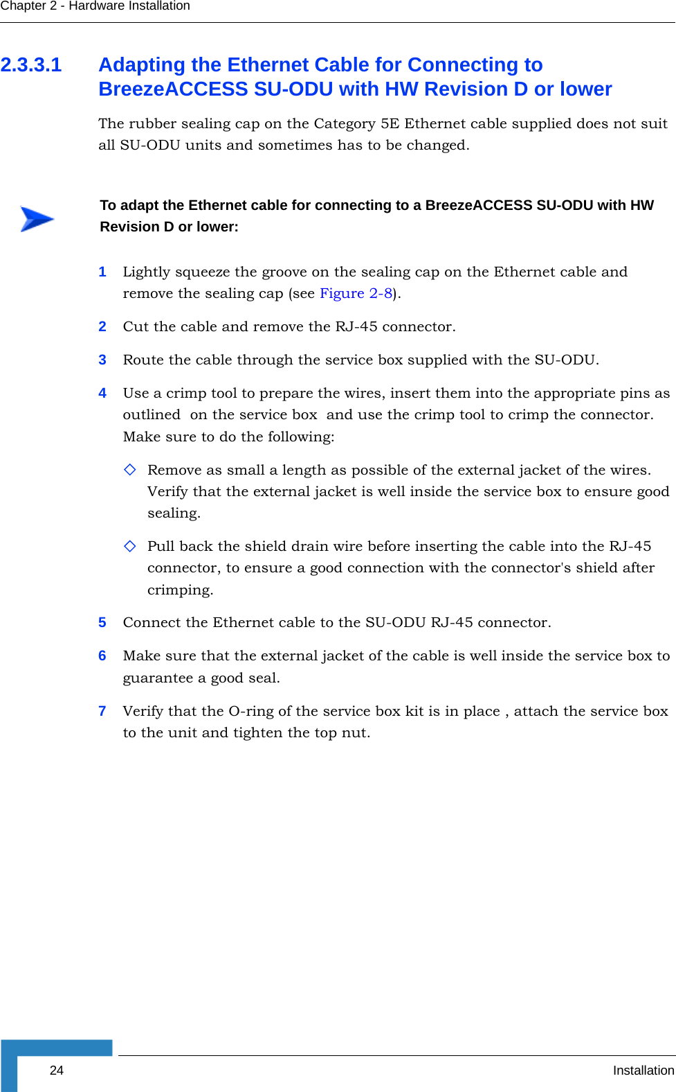
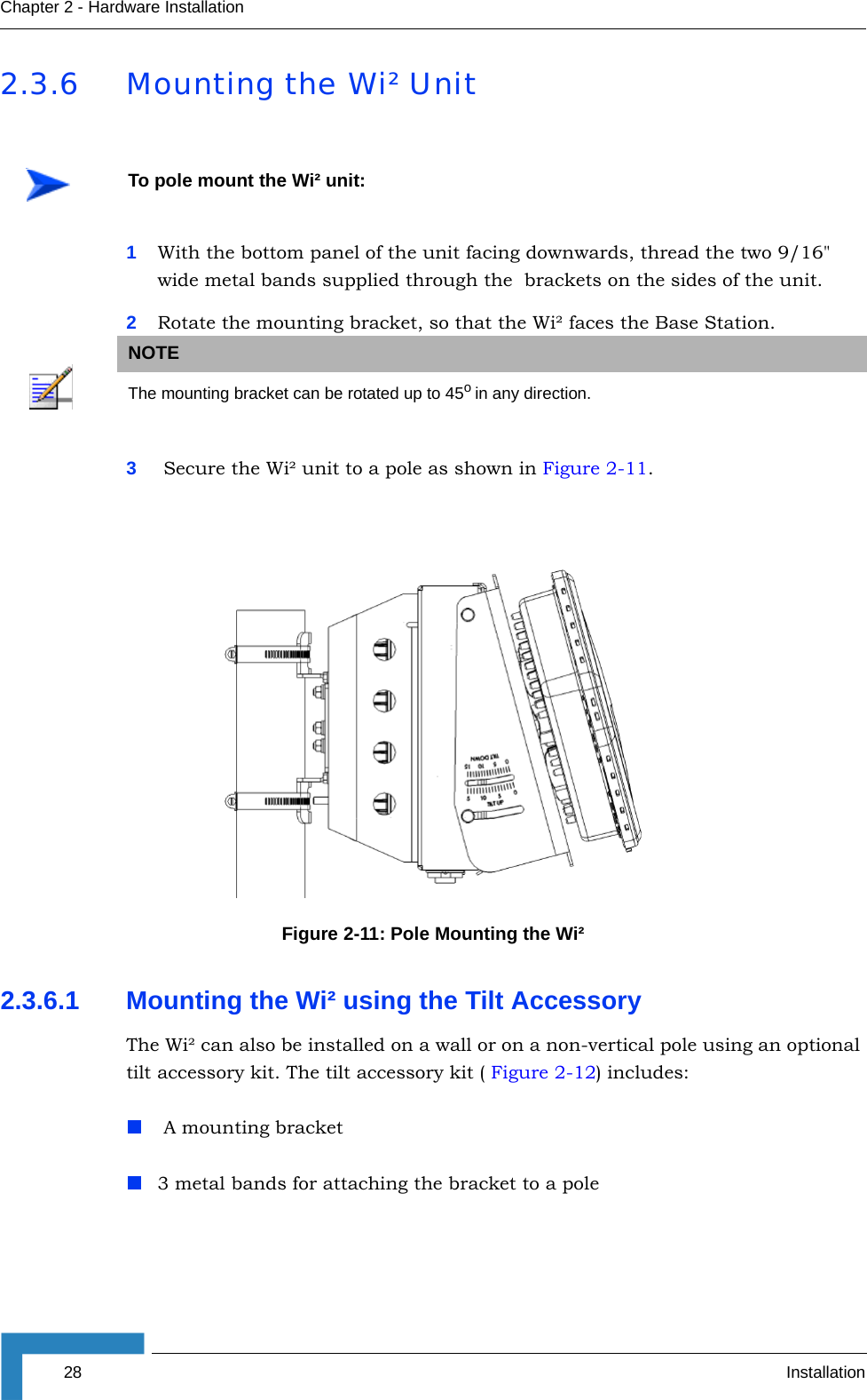
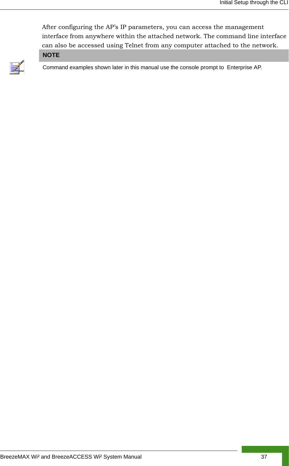
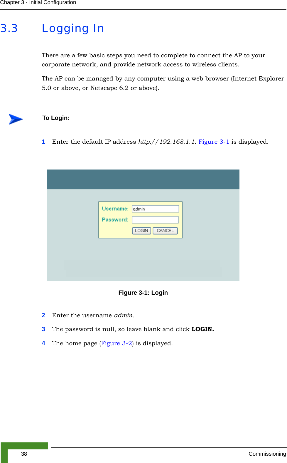
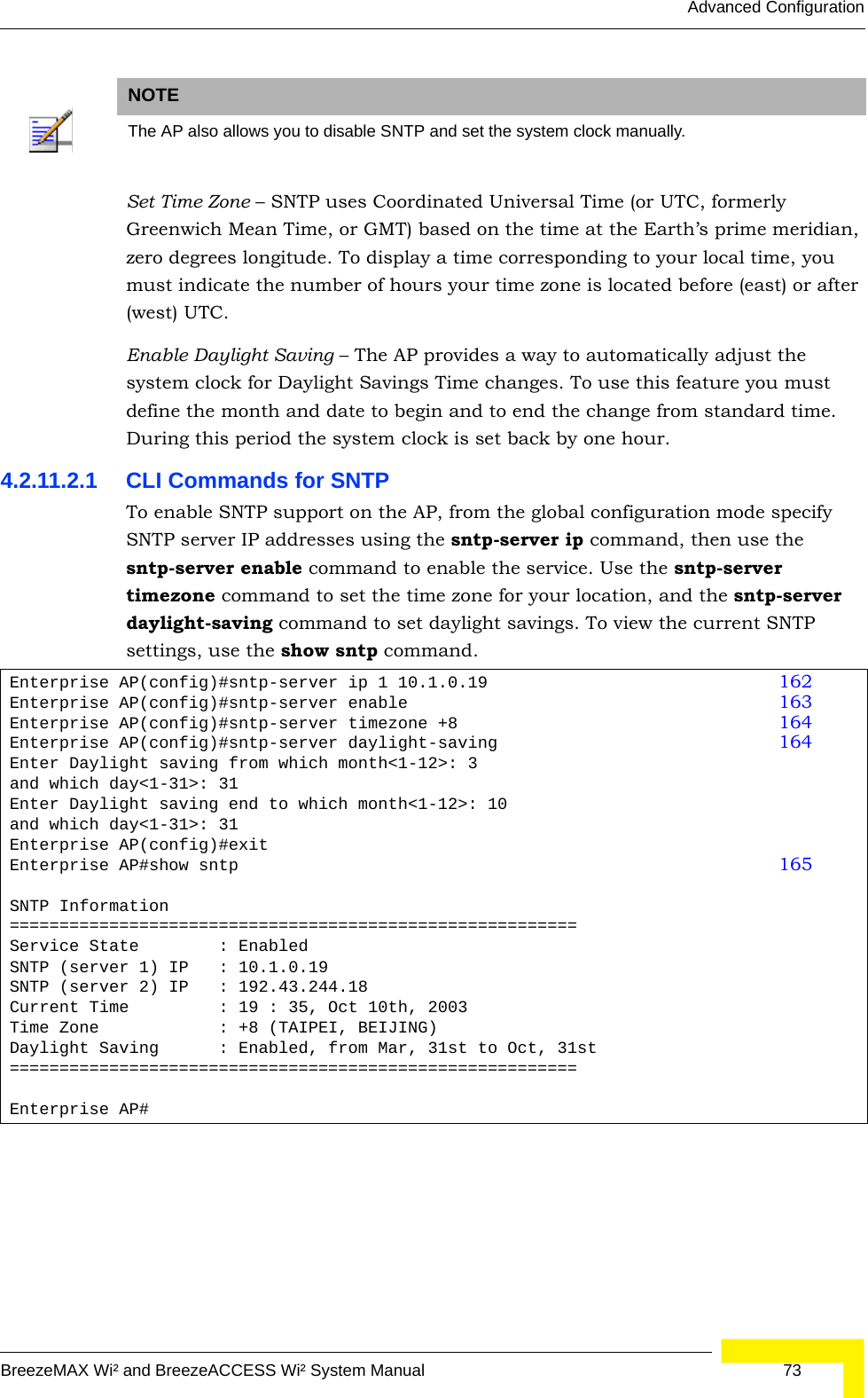
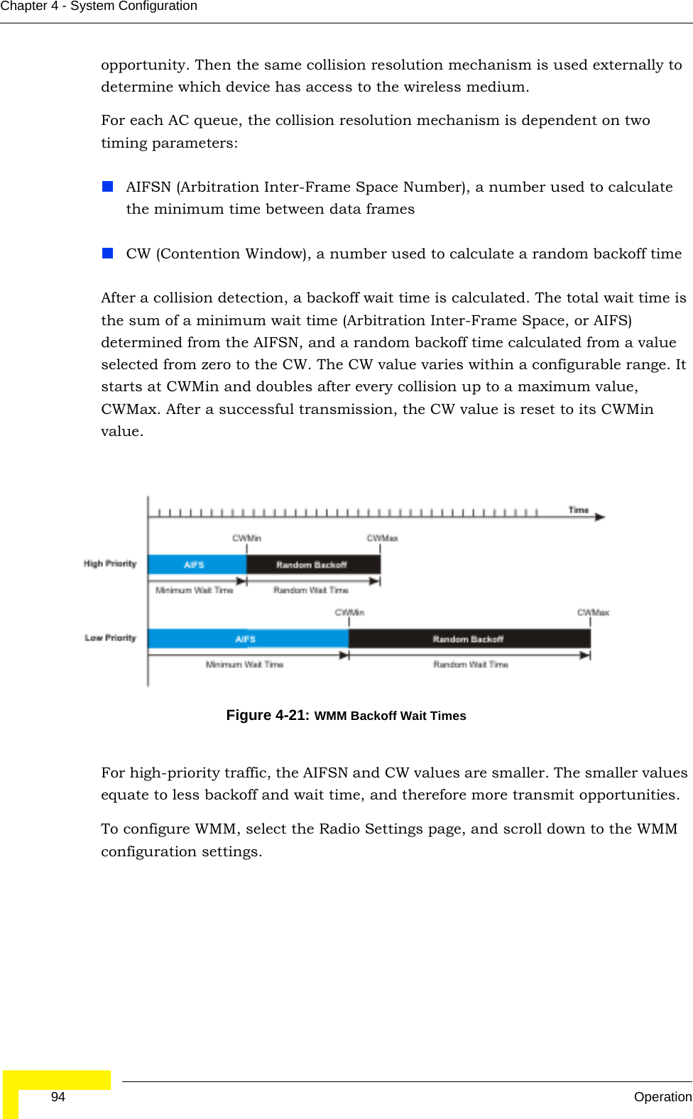
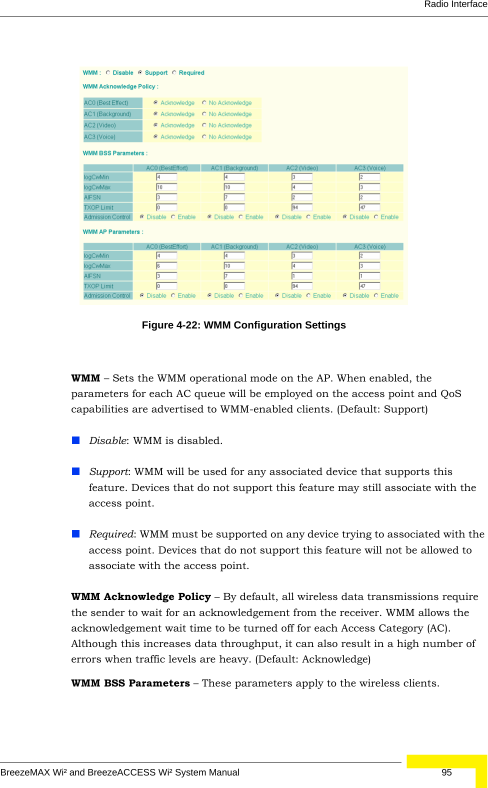
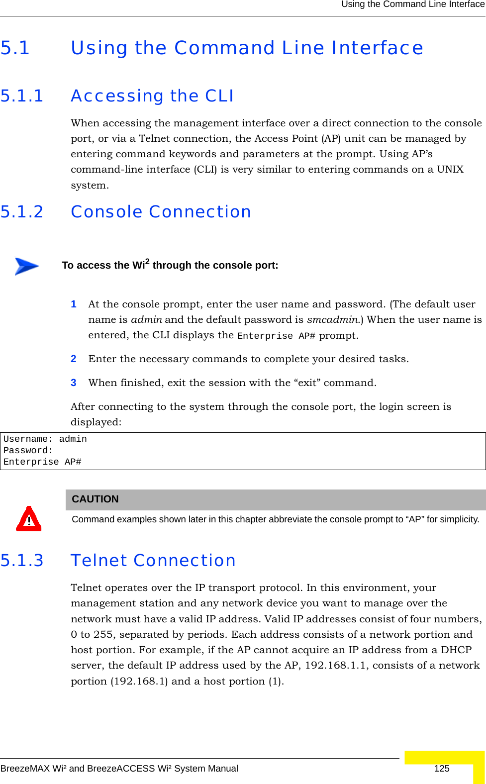
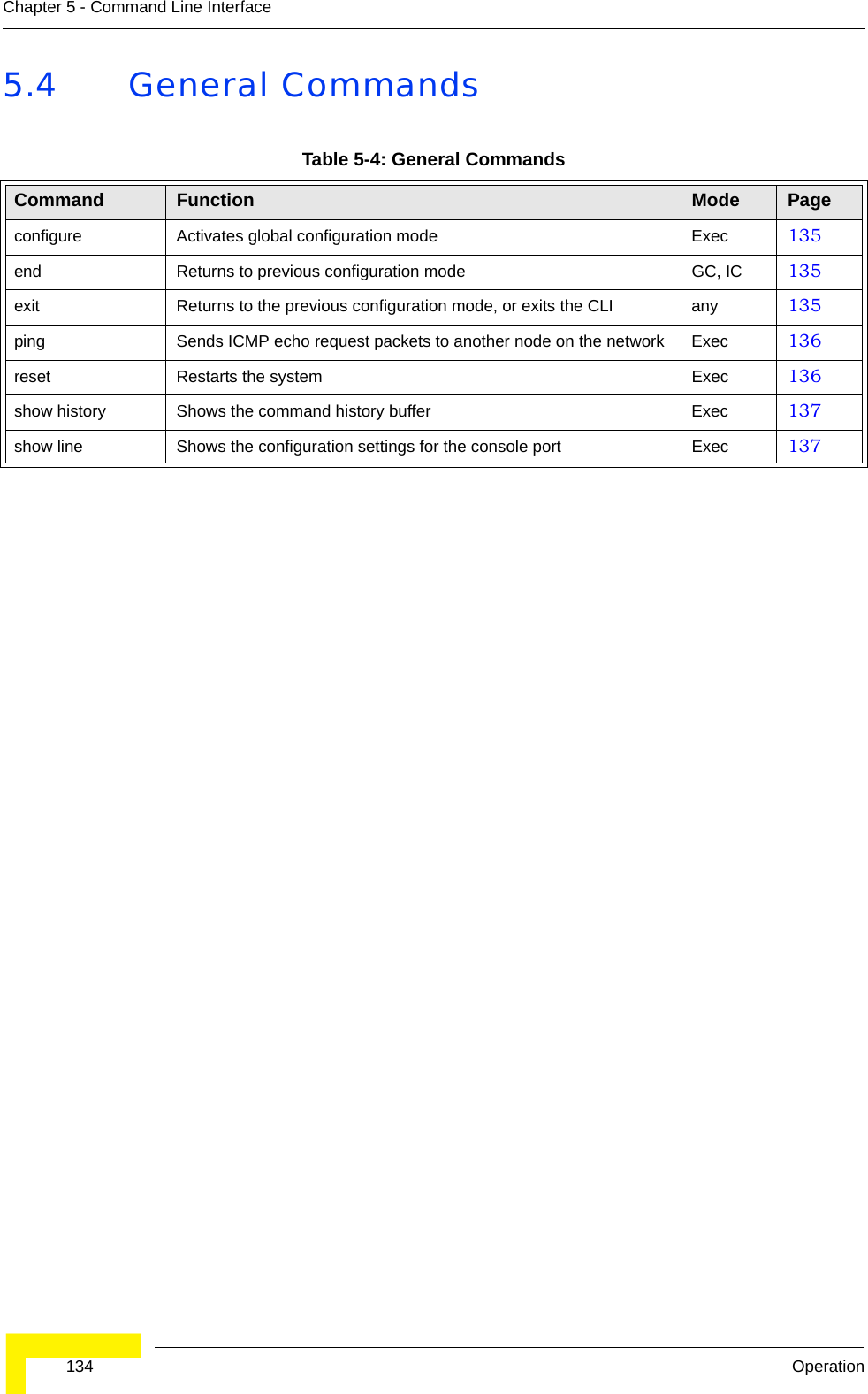
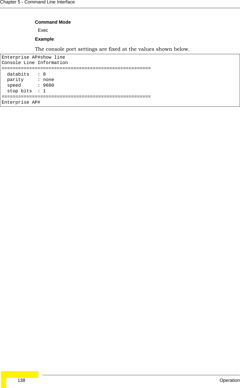
![Initial Setup through the CLIBreezeMAX Wi² and BreezeACCESS Wi² System Manual 353.2 Initial Setup through the CLIFor a description of how to use the CLI, see “Using the Command Line Interface” on page 125. For a list of all the CLI commands and detailed information on using the CLI, refer to “Command Groups” on page 132.3.2.1 Configuration via TelnetBy default, use the Telnet option to configure the unit. The AP uses the default address 192.168.1.1. This address may not be compatible with your network. You will therefore have to use the command line interface (CLI) to assign an IP address that is compatible with your network as described on page 36.Use the category 5 Ethernet data cable (2 pairs crosswire) provided to connect the SU port on the Wi² unit to your PC and Telnet the unit to start the initial setup.3.2.2 Configuration via ConsoleThe Wi² has a console port that enables a connection to a PC or terminal for monitoring and configuration. Attach a VT100-compatible terminal, or a PC running a terminal emulation program to the Wi² using an RS232 console cable. 1Connect the console cable to the serial port on a terminal, or a PC running terminal emulation software.2Connect the other end of the cable to the console port on the Wi² unit.3Make sure the terminal emulation software is set as follows:-:Select the appropriate serial port (COM port 1 or 2).Set the data rate to 9600 baud.Set the data format to 8 data bits, 1 stop bit, and no parity.Set flow control to none.Set the emulation mode to VT100.When using HyperTerminal, select Terminal keys, not Windows keys.4Once you have set up the terminal correctly, press the [Enter] key to initiate the console connection. The console login screen is displayed.To connect to the console port:](https://usermanual.wiki/Accton-Technology/OAP2611A/User-Guide-758212-Page-59.png)
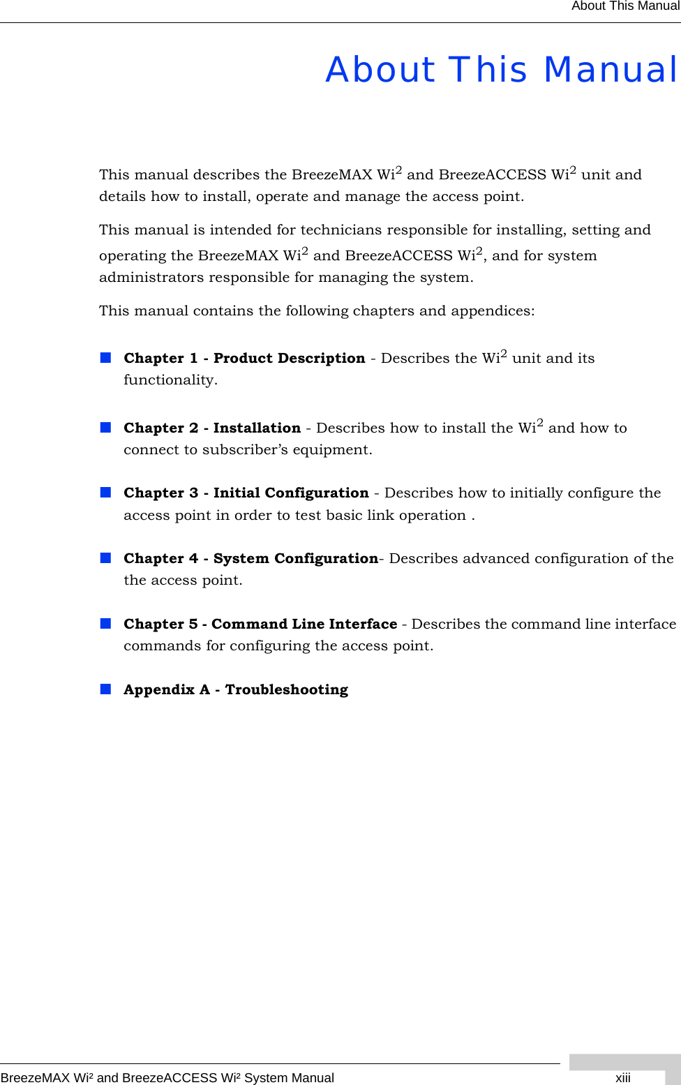
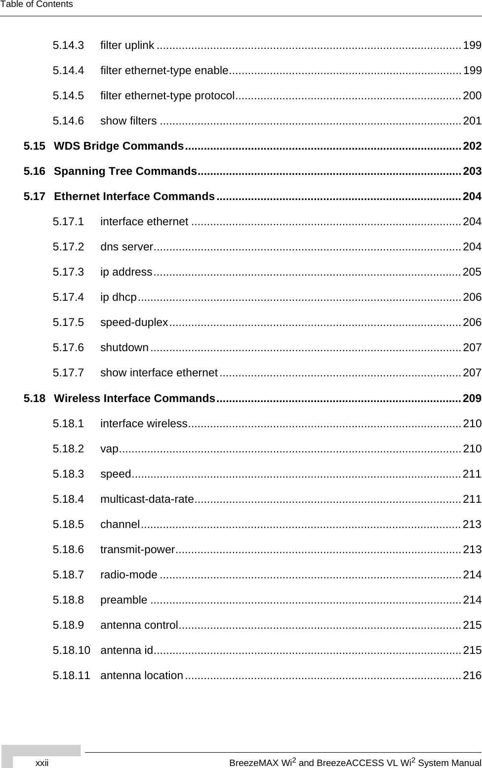
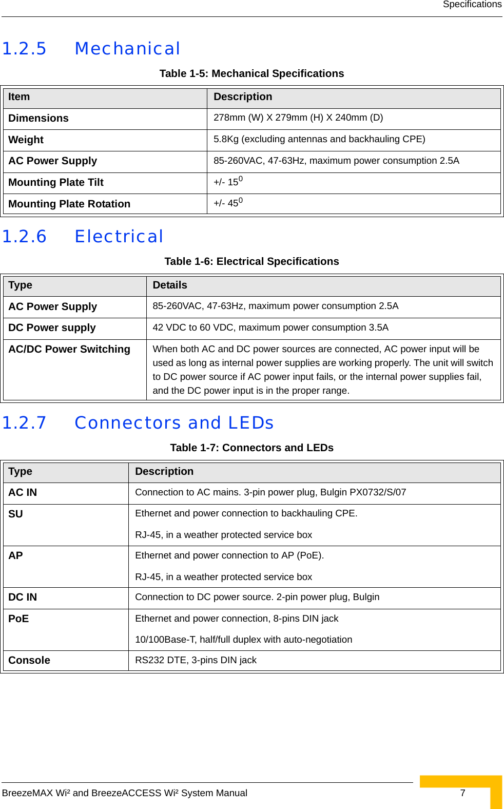
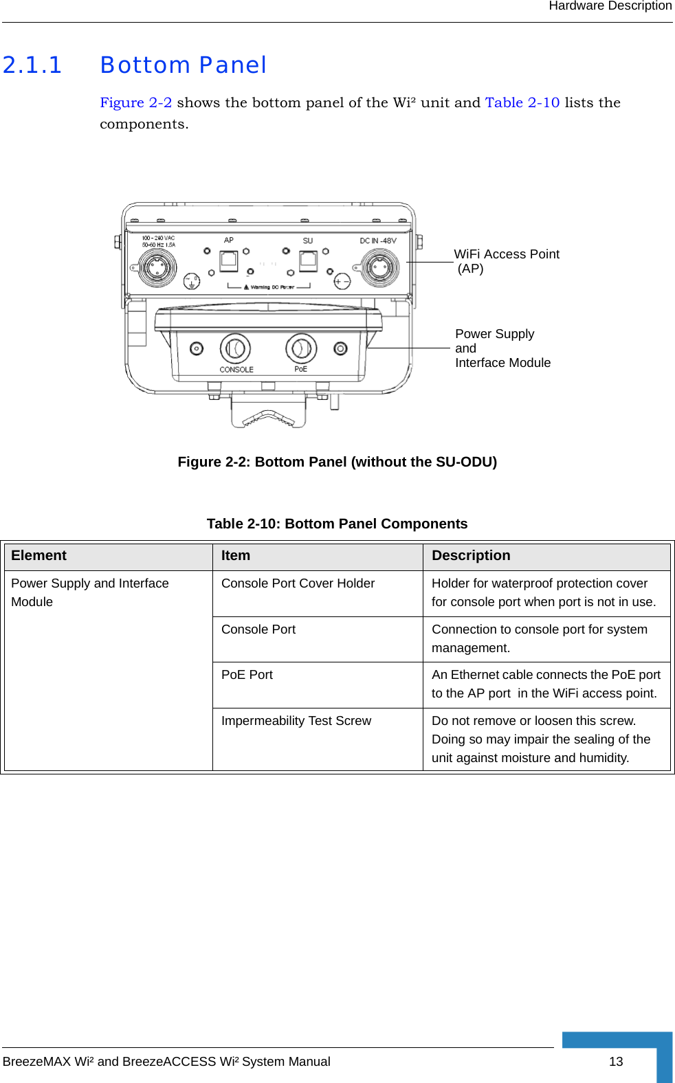
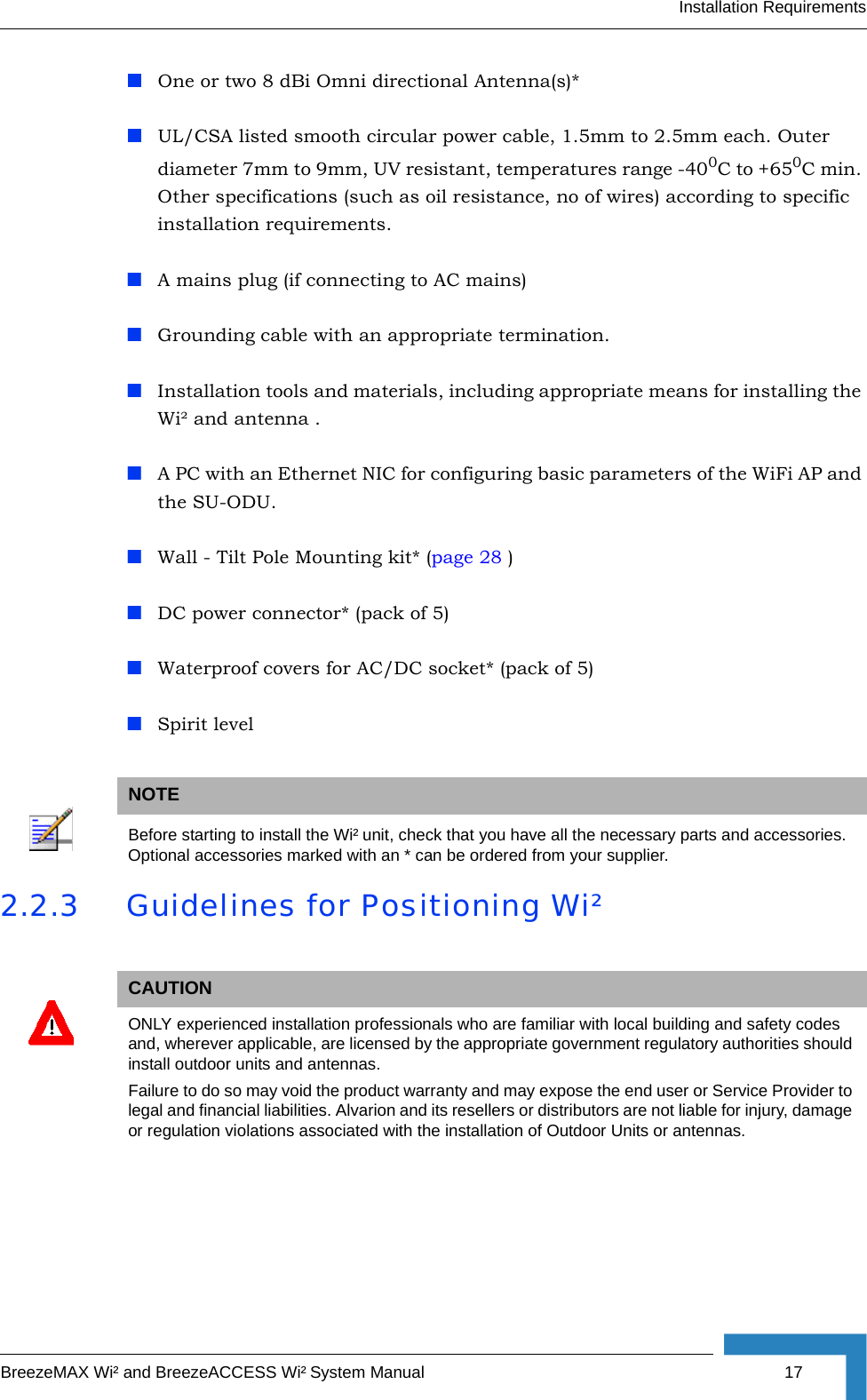
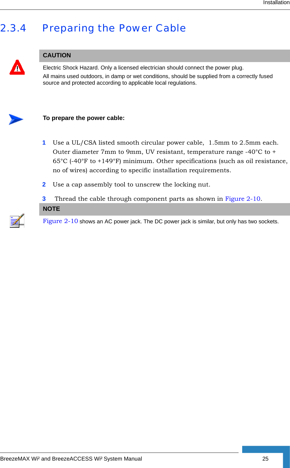
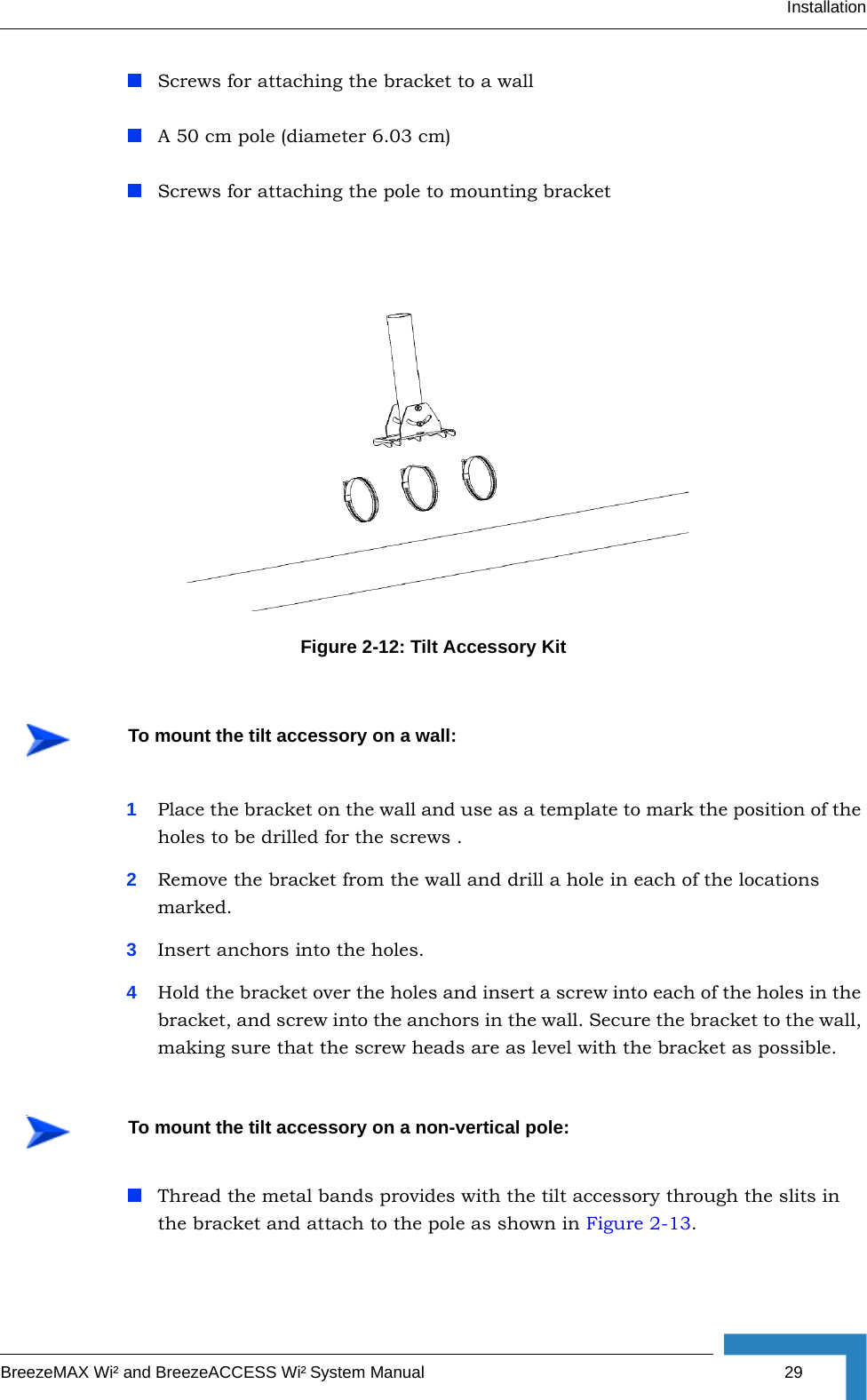
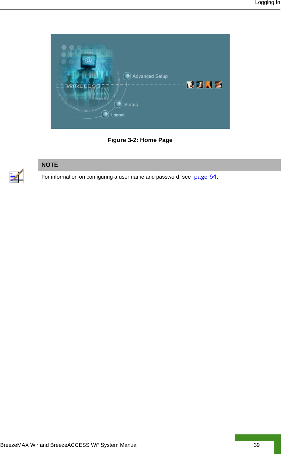
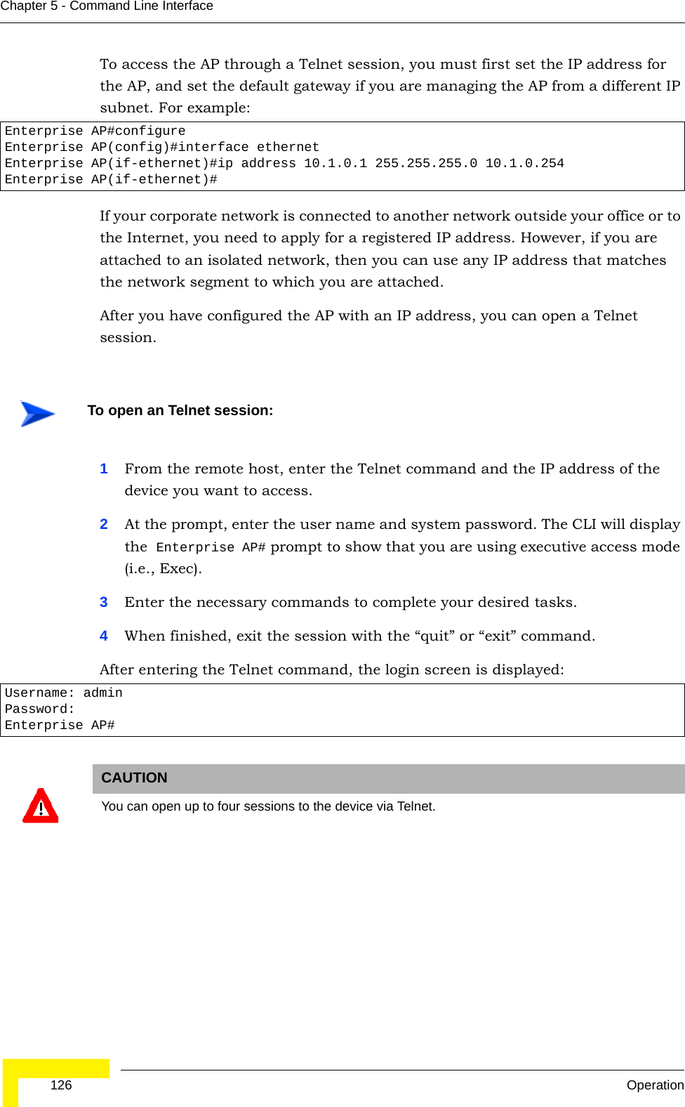
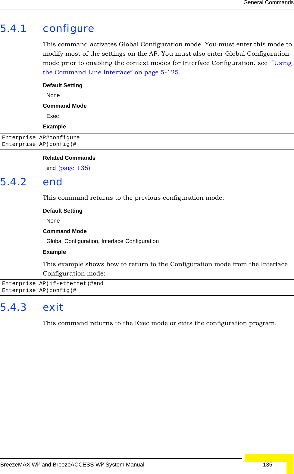
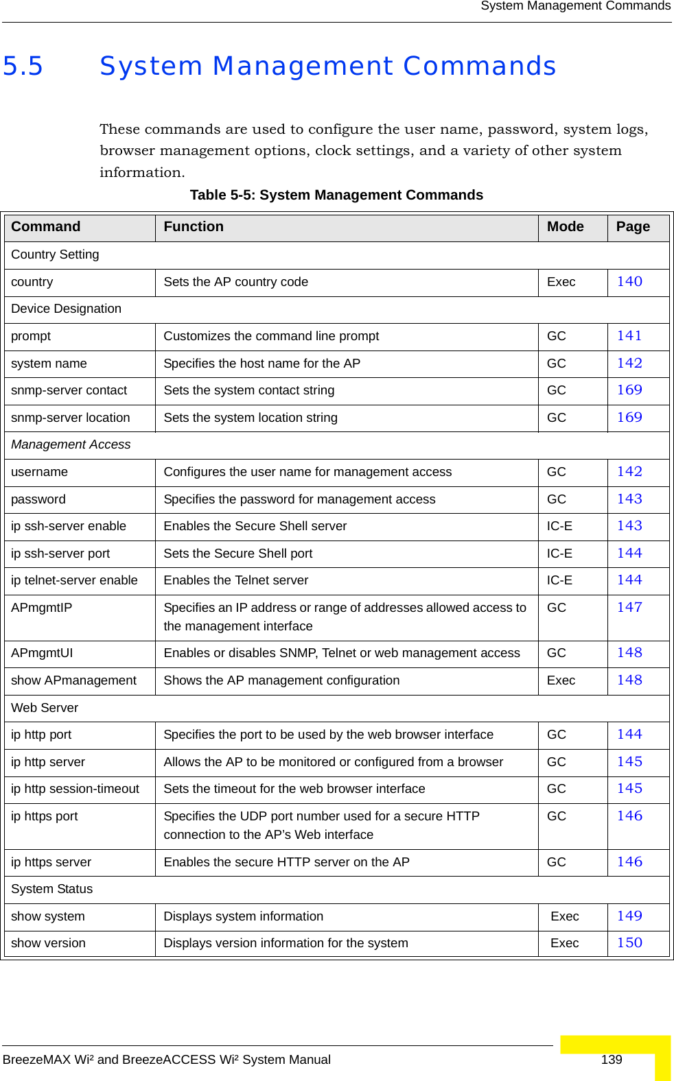
![36 CommissioningChapter 3 - Initial Configuration3.2.3 Initial Configuration StepsLogging In – Enter admin for the user name. The default password is null, so just press [Enter] at the password prompt. The CLI prompt appears displaying Enterprise AP#.Setting the Country Code – You must use the CLI to set the country code. Setting the country code restricts operation of the AP to the radio channels and transmit power levels permitted for wireless networks in the specified country. Type exit to leave configuration mode. Then type country ? to display the list of countries. Select the code for your country, and enter the country command again, following by your country code (e.g., tw for Taiwan).Setting the IP Address – By default, the AP is configured to obtain IP address settings from a DHCP server. If a DHCP server is not available, the IP address defaults to 192.168.1.1, which may not be compatible with your network. You will therefore have to use the command line interface (CLI) to assign an IP address that is compatible with your network. Type configure to enter configuration mode, then type interface ethernet to access the Ethernet interface-configuration mode.First type no ip dhcp to disable DHCP client mode. Then type ip address and the ip-address netmask gateway, where ip-address is the AP’s IP address, netmask is the network mask for the network, and gateway is the default gateway router. Check with your system administrator to obtain an IP address that is compatible with your network.Username: adminPassword: Enterprise AP#NOTEFor American and Canadian customers only channels 1~11 are permitted. Setting of other channels is not possible. Enterprise AP#country twEnterprise AP#Enterprise AP#configureEnterprise AP(config)#interface ethernetEnterprise AP(config-if)#Enterprise AP(if-ethernet)#no ip dhcpEnterprise AP(if-ethernet)#ip address 192.168.2.2 255.255.255.0 192.168.2.254Enterprise AP(if-ethernet)#](https://usermanual.wiki/Accton-Technology/OAP2611A/User-Guide-758212-Page-60.png)
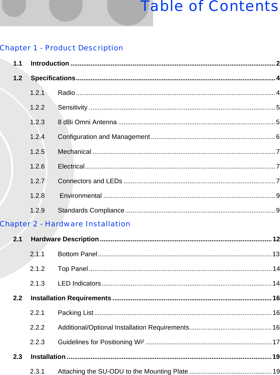
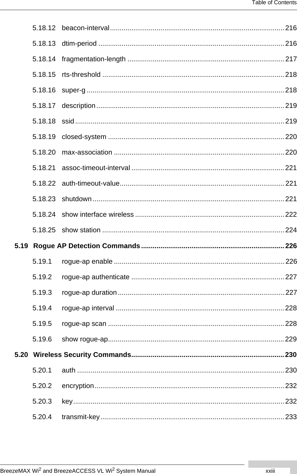
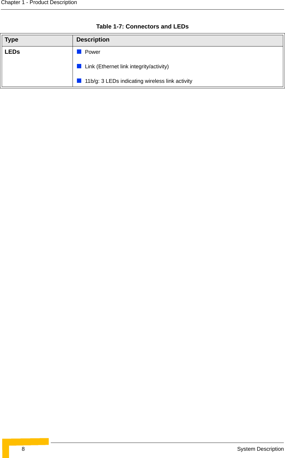
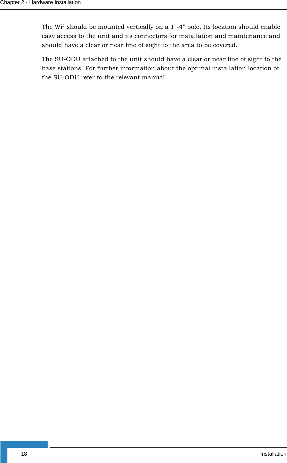
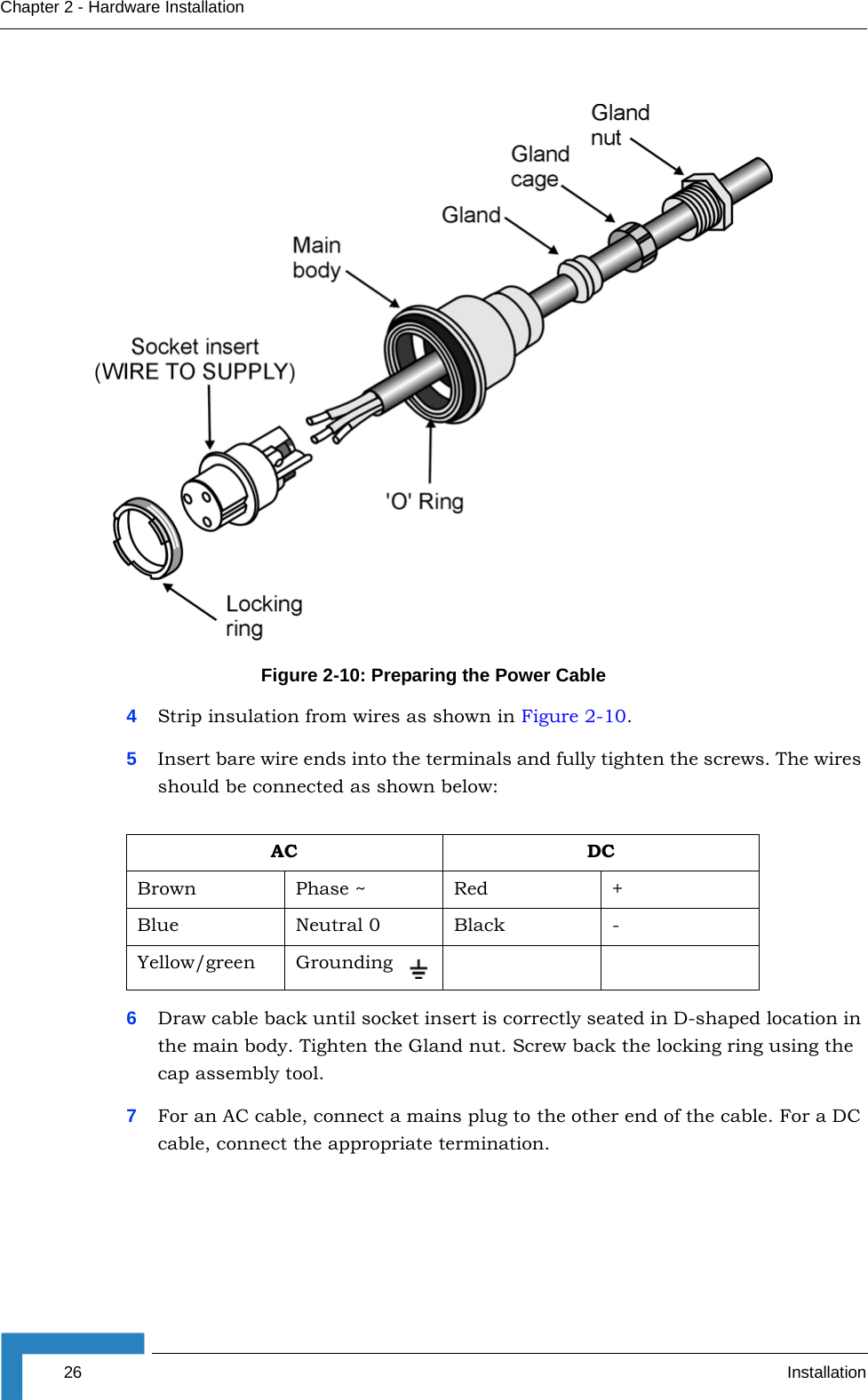
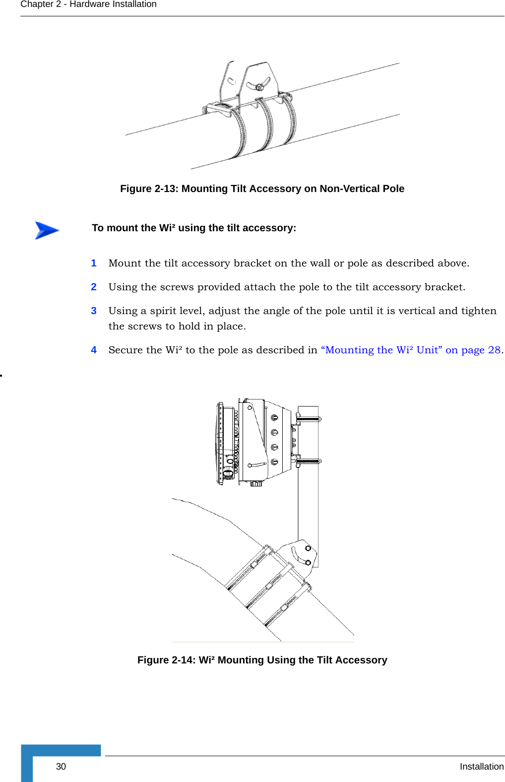
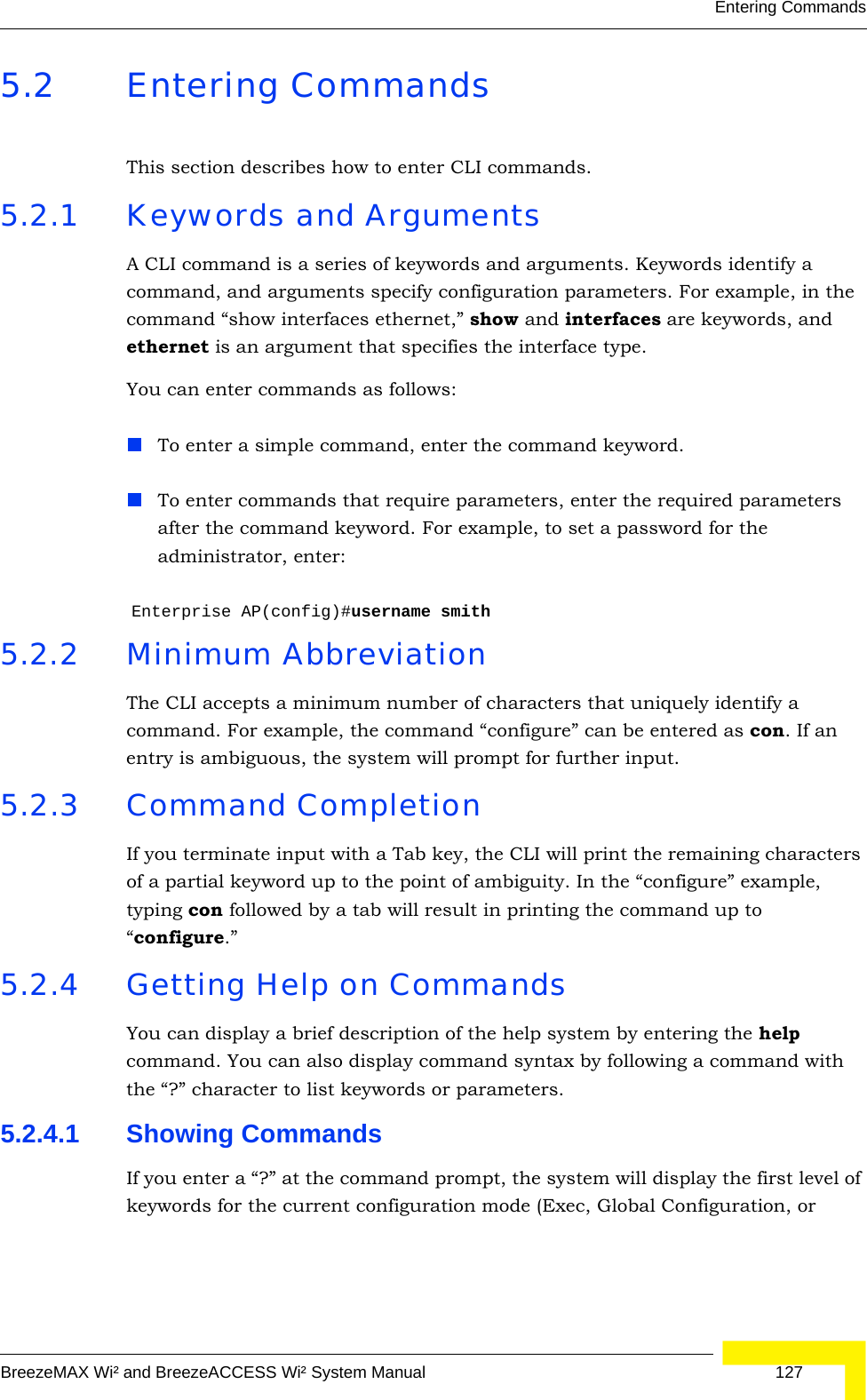
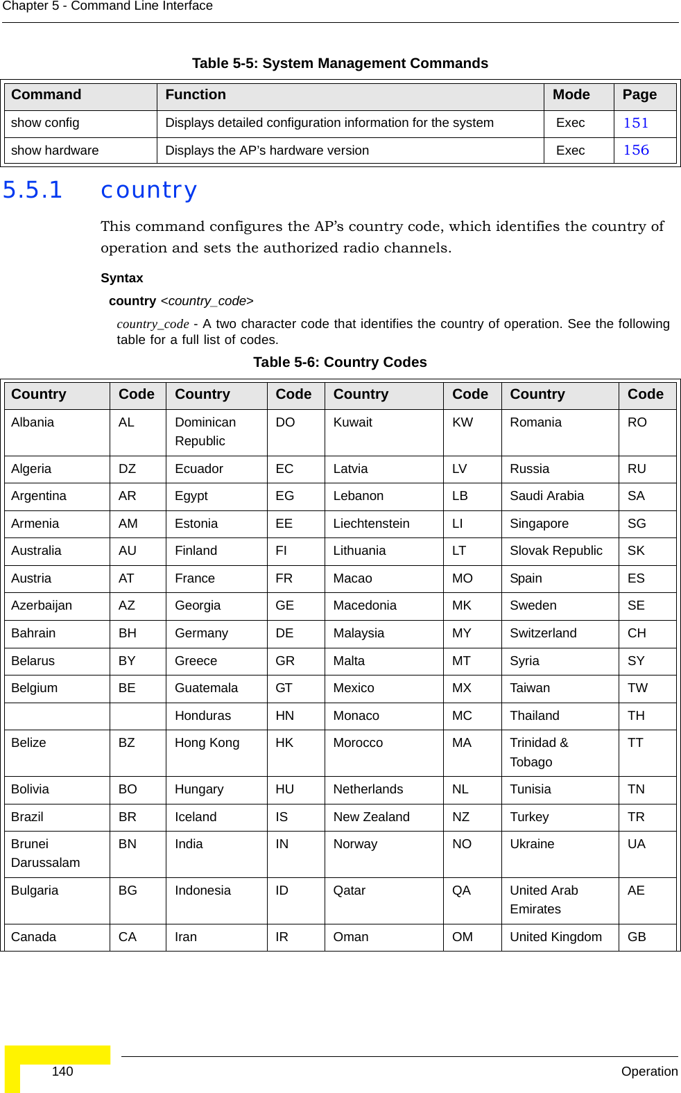
![Advanced ConfigurationBreezeMAX Wi² and BreezeACCESS Wi² System Manual 69the dir command can be used to check that the new file is present in the AP file system. To run the new software, use the reset board command to reboot the AP.Enterprise AP#copy tftp file 1811. Application image2. Config file3. Boot block imageSelect the type of download<1,2,3>: [1]:1TFTP Source file name:img.binTFTP Server IP:192.168.1.19Enterprise AP#dir 183File Name Type File Size-------------------------- ---- -----------dflt-img.bin 2 1319939img.bin 2 1629577syscfg 5 17776syscfg_bak 5 17776 262144 byte(s) availableEnterprise AP#reset board 136Reboot system now? <y/n>: y](https://usermanual.wiki/Accton-Technology/OAP2611A/User-Guide-758212-Page-93.png)
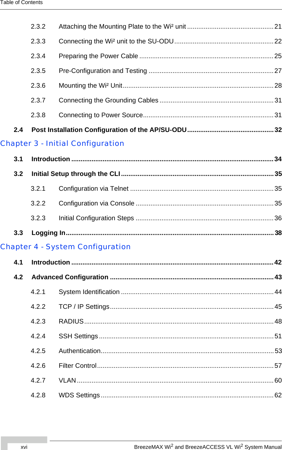
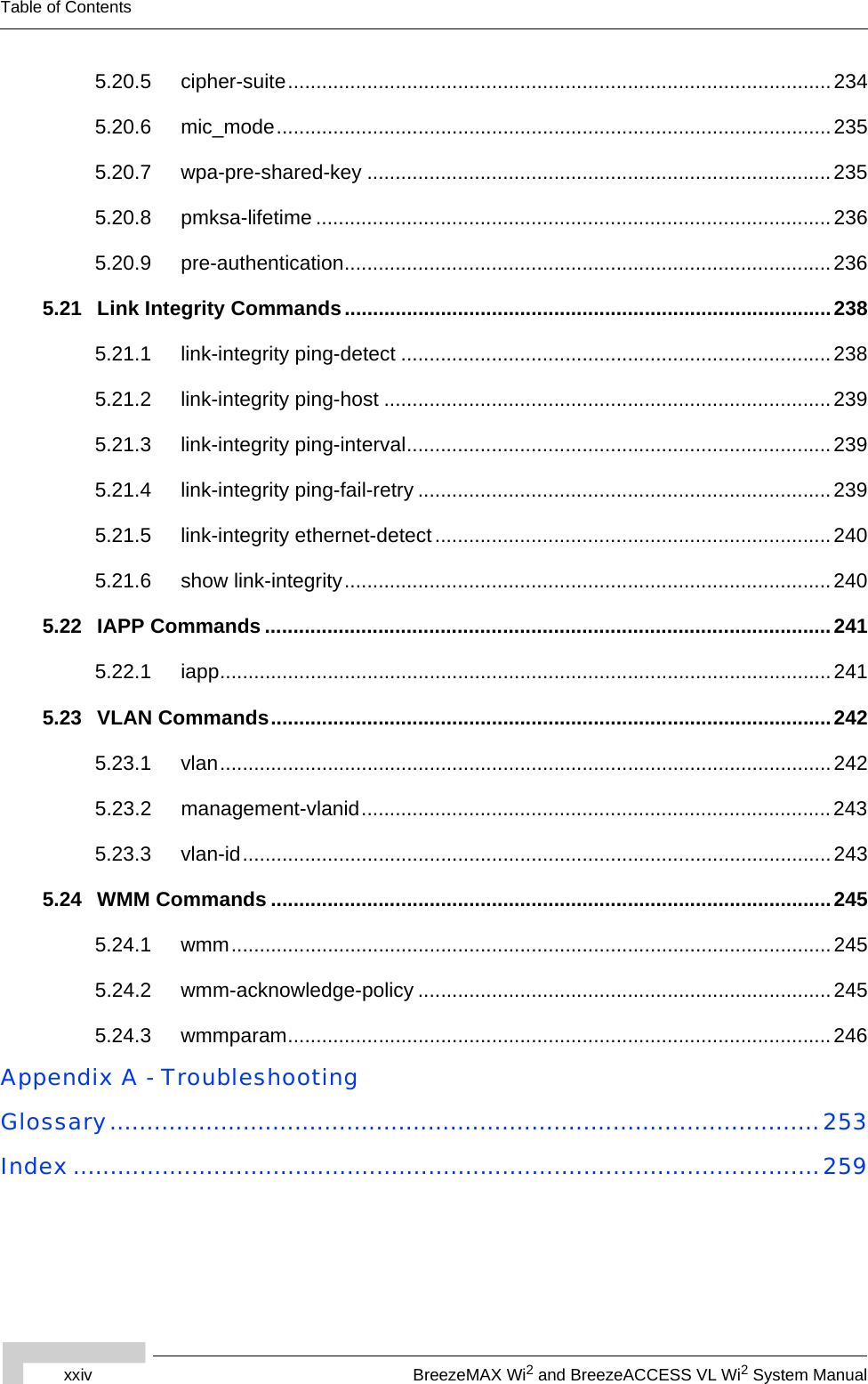
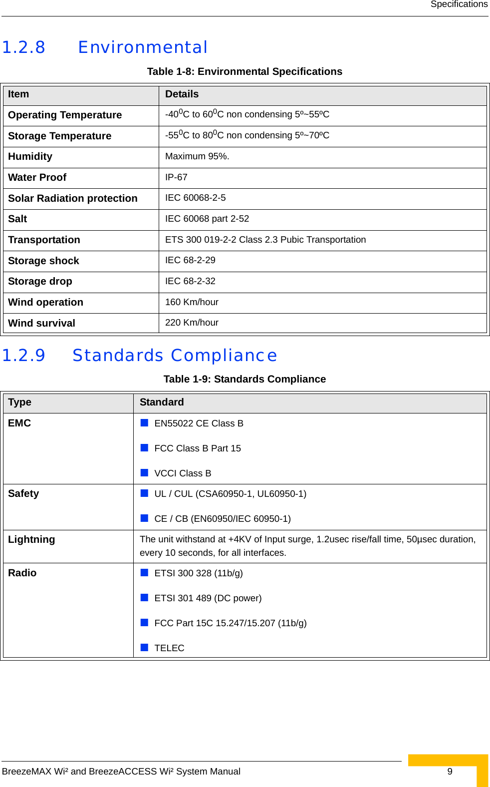
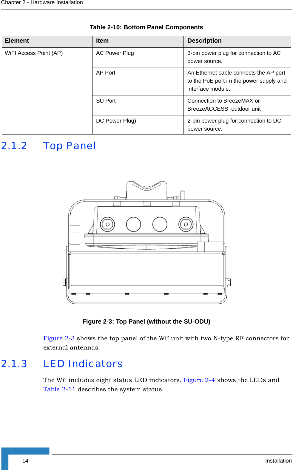
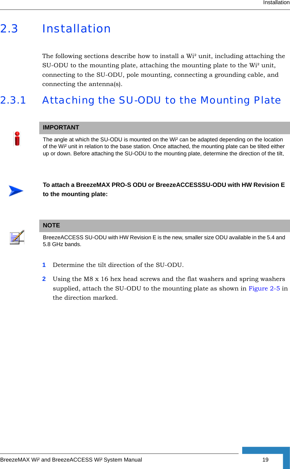
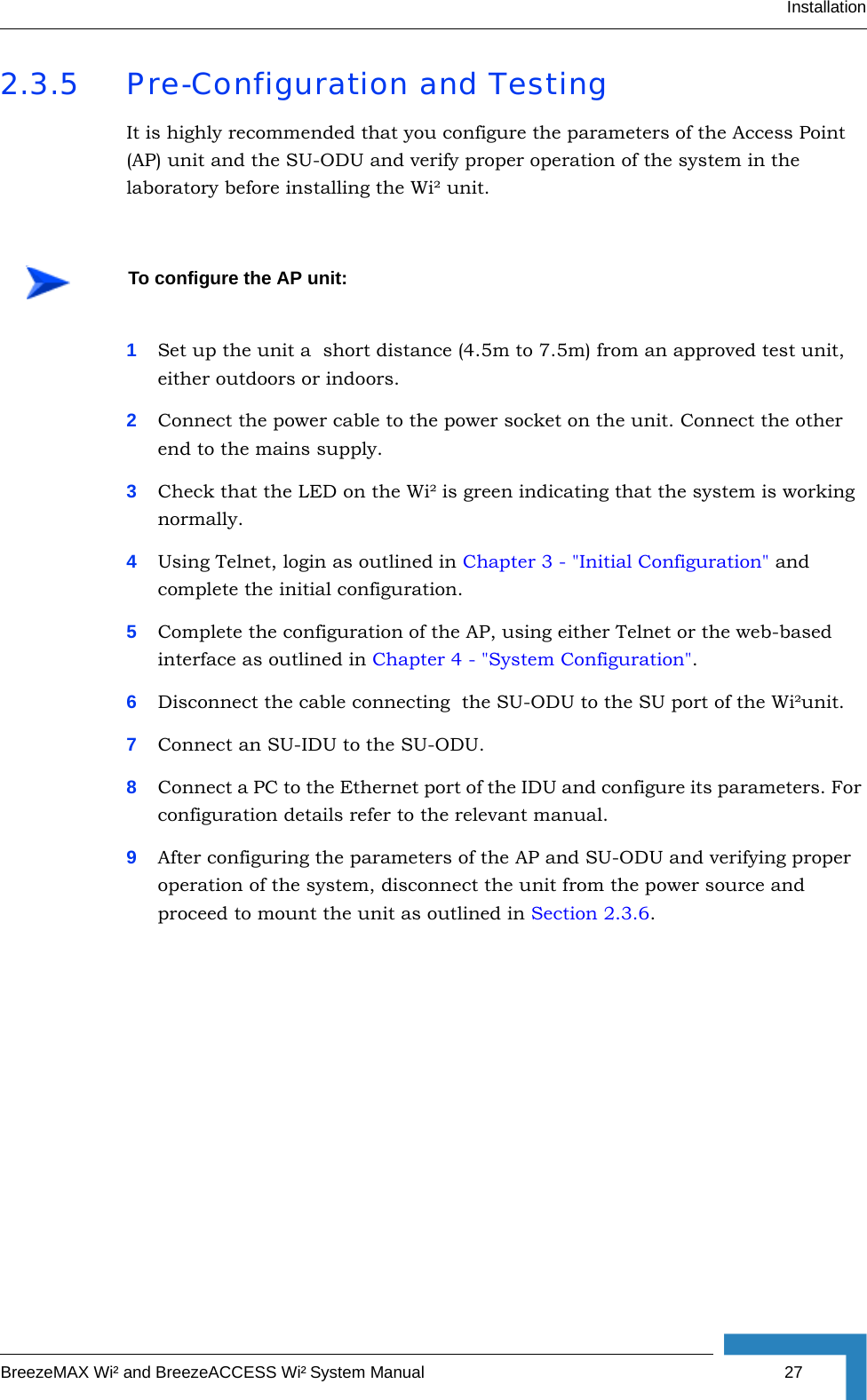
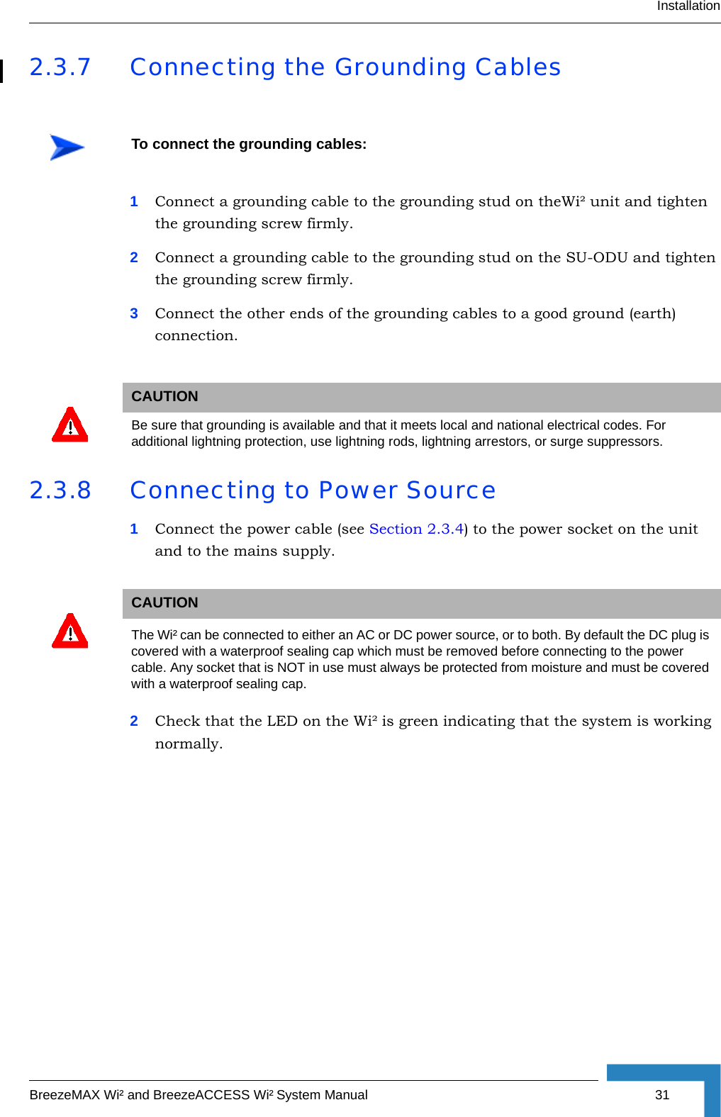
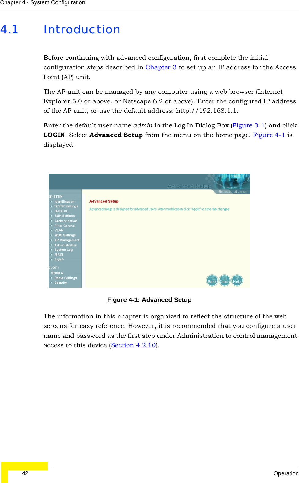
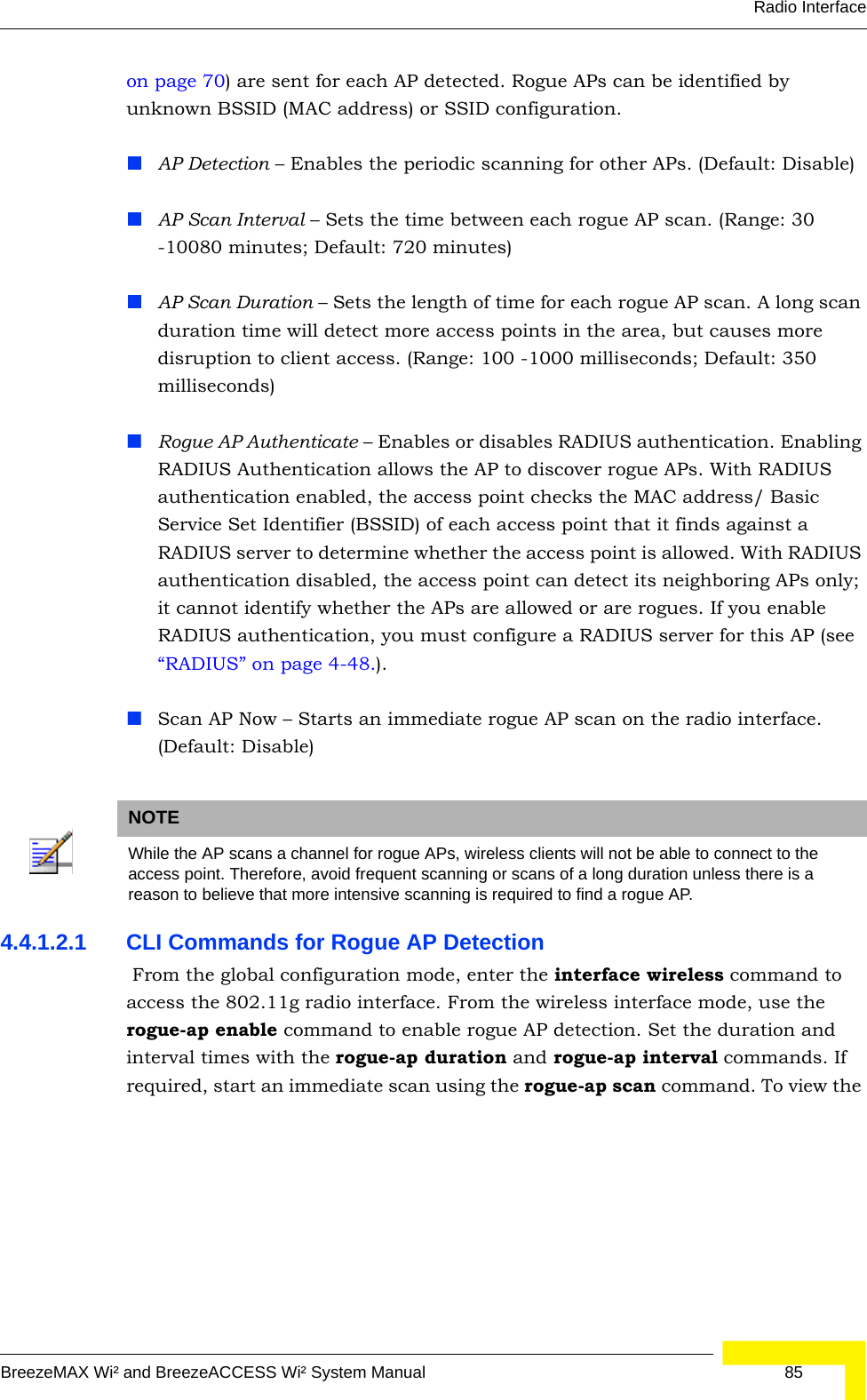
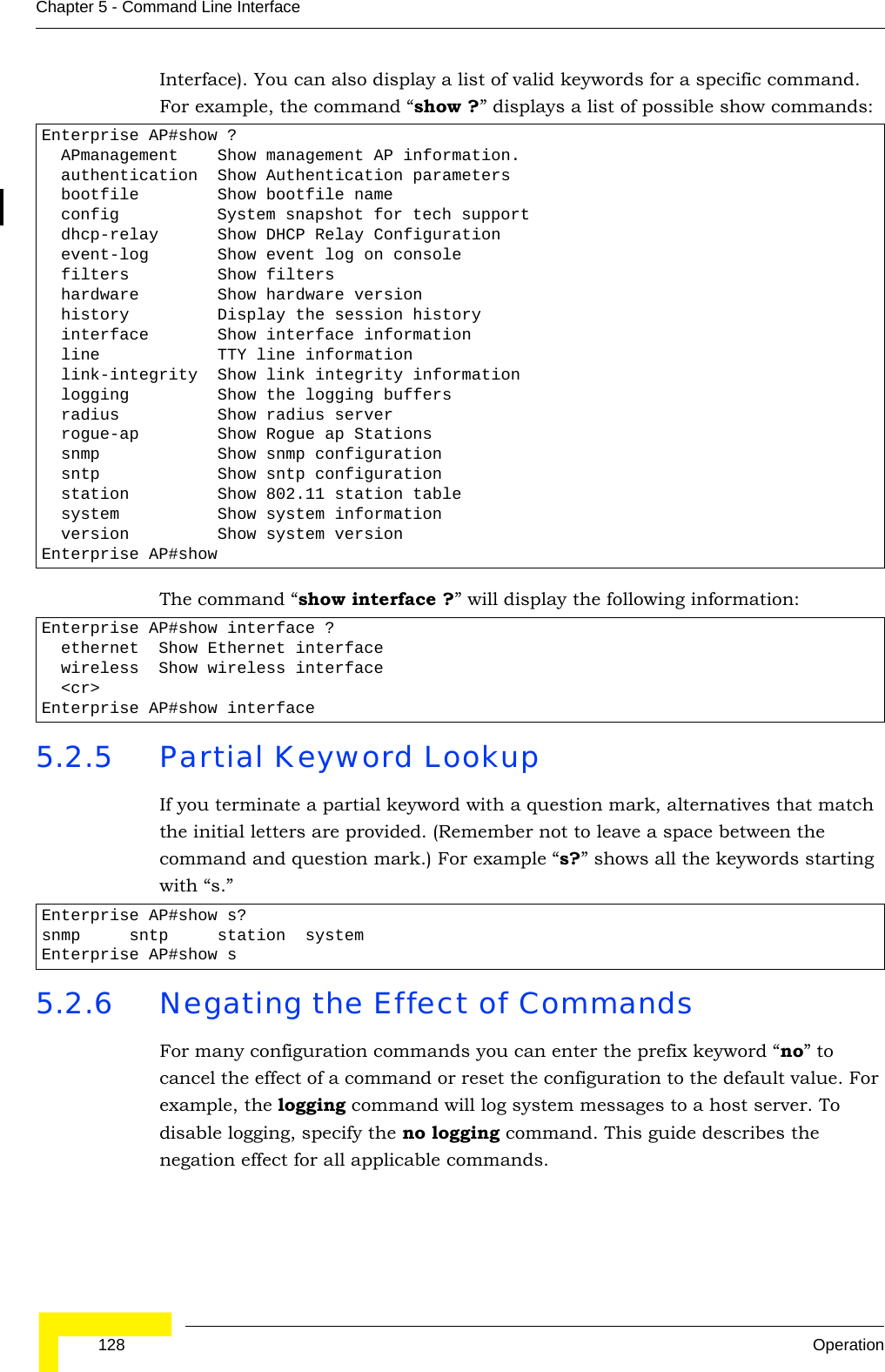
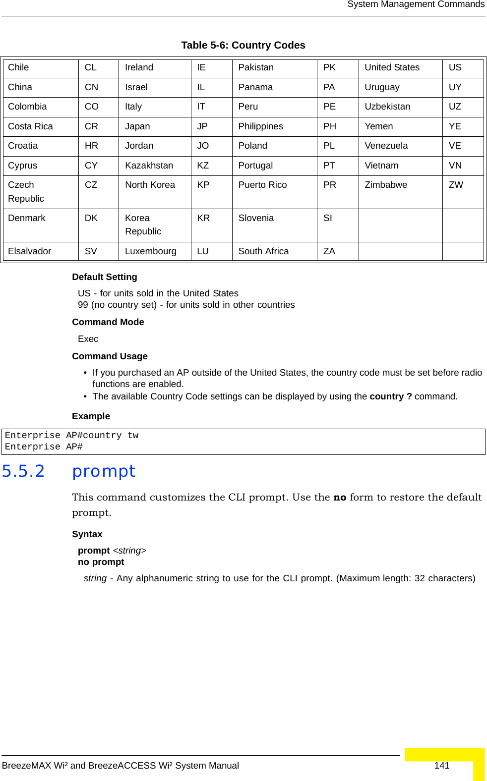
![84 OperationChapter 4 - System Configurationinterface (numbered 0 to 3), use the vap command. You can configure a name for each interface using the description command. You can also use the closed-system command to stop sending the SSID in beacon messages. Set any other VAP parameters and radio setting as required before enabling the VAP interface (with the no shutdown command). To view the current 802.11g radio settings for the VAP interface, use the show interface wireless g [0-3] command as shown on page 210. 4.4.1.2 Configuring Rogue AP DetectionTo configure Rouge AP detection, select the Radio Settings page, and scroll down to the Rouge AP section.Rogue AP – A “rogue AP” is either an AP that is not authorized to participate in the wireless network, or an AP that does not have the correct security configuration. Rogue APs can allow unauthorized access to the network, or fool client stations into mistakenly associating with them and thereby blocking access to network resources. The AP can be configured to periodically scan all radio channels and find other APs within range. A database of nearby APs is maintained where any rogue APs can be identified. During a scan, Syslog messages (see “Enabling System Logging” Enterprise AP(if-wireless g)#vap 0 210Enterprise AP(if-wireless g: VAP[0])#description RD-AP#3 219Enterprise AP(if-wireless g: VAP[0])#vlan-id 1 243Enterprise AP(if-wireless g: VAP[0])#closed-system 220Enterprise AP(if-wireless g: VAP[0])#authentication-timeout- interval 30 221Enterprise AP(if-wireless g: VAP[0])#association-timeout- interval 20 221Enterprise AP(if-wireless g: VAP[0])#max-association 32 220Enterprise AP(if-wireless g: VAP[0])#pmksa-lifetime 900 236Enterprise AP(if-wireless g: VAP[0])#Figure 4-19: Rouge AP Section of Radio Settings page](https://usermanual.wiki/Accton-Technology/OAP2611A/User-Guide-758212-Page-108.png)
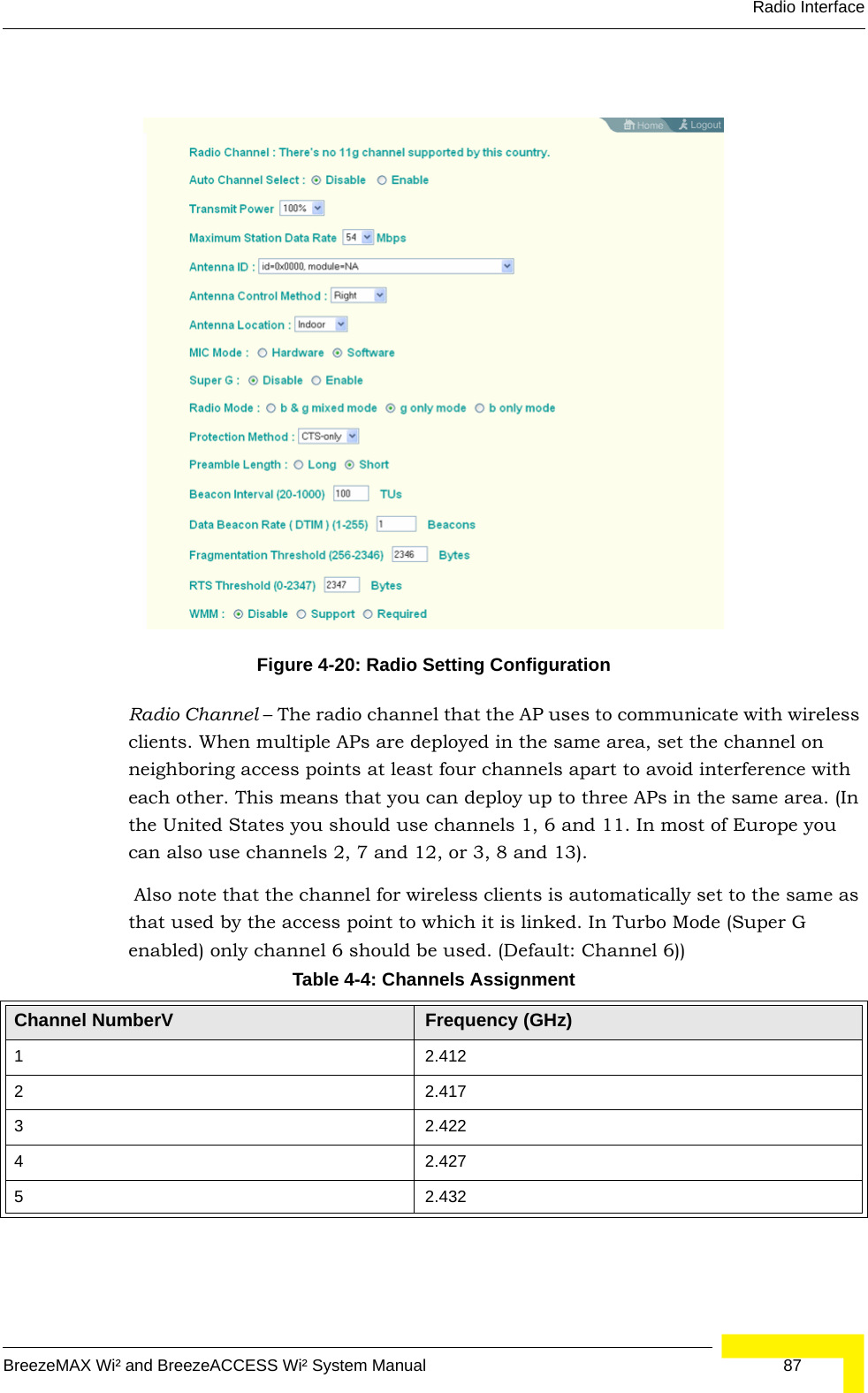
![92 OperationChapter 4 - System Configurationinterface, use the show interface wireless g [0~3] command as shown on page 210.4.4.1.2.3 CLI Commands for the Radio Settings From the global configuration mode, enter the interface wireless g command to access the 802.11g radio interface. From the 802.11g interface mode, you can access radio settings that apply to all VAP interfaces. Use the turbo command to enable this feature before setting the radio channel with the channel command. Set any other radio setting as required before enabling the VAP interface (with the no shutdown command). To view the current 802.11g radio settings for the VAP interface, use the show interface wireless g [0~3] command as shown on page 210.4.4.1.3 Configuring WiFi MultimediaWireless networks offer an equal opportunity for all devices to transmit data from any type of application. Although this is acceptable for most applications, multimedia applications (with audio and video) are particularly sensitive to the delay and throughput variations that result from this “equal opportunity” wireless access method. For multimedia applications to run well over a wireless network, a Enterprise AP(config)#interface wireless g 210Enter Wireless configuration commands, one per line.Enterprise AP(if-wireless g)#radio-mode g 214Enterprise AP(if-wireless g)#channel auto 213Enterprise AP(if-wireless g)#transmit-power full 213Enterprise AP(if-wireless g)#super-g 218Enterprise AP(if-wireless g)#preamble short 214Enterprise AP(if-wireless g)#Enterprise AP(config)#interface wireless g 210Enter Wireless configuration commands, one per line.Enterprise AP(if-wireless g)#channel 42 213Enterprise AP(if-wireless g)#transmit-power full 213Enterprise AP(if-wireless g)#speed 9 211Enterprise AP(if-wireless g)#antenna id 0000 215Enterprise AP(if-wireless g)#antenna control right 215Enterprise AP(if-wireless g)#antenna location outdoor 216Enterprise AP(if-wireless g)#mic_mode hardware 235Enterprise AP(if-wireless g)#super-g 218Enterprise AP(if-wireless g)#beacon-interval 150 216Enterprise AP(if-wireless g)#beacon-interval 150Enterprise AP(if-wireless g)#dtim-period 5 216Enterprise AP(if-wireless g)#multicast-data-rate 6 211Enterprise AP(if-wireless g)#fragmentation-length 512 217Enterprise AP(if-wireless g)#rts-threshold 256 218Enterprise AP(if-wireless g)#](https://usermanual.wiki/Accton-Technology/OAP2611A/User-Guide-758212-Page-116.png)
![Radio InterfaceBreezeMAX Wi² and BreezeACCESS Wi² System Manual 97To view the current 802.11g radio settings for the VAP interface, use the show interface wireless g [0-3] command.Enterprise AP#show interface wireless g 0 222Wireless Interface Information=============================================================--------------------Identification---------------------------Description : Enterprise 802.11g Access PointSSID : VAP_TEST_11G 0Turbo Mode : DISABLEDChannel : 36 (AUTO)Status : DISABLEDMAC Address : 00:12:cf:05:95:0c----------------802.11 Parameters---------------------------Transmit Power : FULL (16 dBm)Max Station Data Rate : 54MbpsMulticast Data Rate : 6MbpsFragmentation Threshold : 2346 bytesRTS Threshold : 2347 bytesBeacon Interval : 100 TUsAuthentication Timeout Interval : 60 MinsAssociation Timeout Interval : 30 MinsDTIM Interval : 1 beaconMaximum Association : 64 stationsMIC Mode : SoftwareSuper G : DisabledVLAN ID : 1----------------Security-------------------------------------Closed System : DisabledMulticast cipher : WEPWPA clients : TKIP and AESWPA Key Mgmt Mode : PRE SHARED KEYWPA PSK Key Type : PASSPHRASEEncryption : DISABLEDDefault Transmit Key : 1Common Static Keys : Key 1: EMPTY Key 2: EMPTY Key 3: EMPTY Key 4: EMPTYAuthentication Type : OPEN----------------802.1x---------------------------------------802.1x :Broadcast Key Refresh Rate : 30 minSession Key Refresh Rate : 30 min802.1x Session Timeout Value : 0 min----------------Antenna--------------------------------------Antenna Control method : DiversityAntenna ID : 0x0000(Default Antenna)Antenna Location : Outdoor](https://usermanual.wiki/Accton-Technology/OAP2611A/User-Guide-758212-Page-121.png)
![Radio InterfaceBreezeMAX Wi² and BreezeACCESS Wi² System Manual 107Open System: If you don’t set up any other security mechanism on the access point, the network has no protection and is open to all users. This is the default setting.Shared Key: Sets the access point to use WEP shared keys. If this option is selected, you must configure at least one key on the access point and all clients.Encryption – Enable or disable the access point to use data encryption (WEP, TKIP, or AES). If this option is selected when using static WEP keys, you must configure at least one key on the access point and all clients. (Default: Disabled)4.4.2.2.1 CLI Commands for WEP Shared Key Security To enable WEP shared key security for the 802.11g interface, use the interface wireless g command from the CLI configuration mode to access the interface mode for the 802.11g radio. First use the key command to define up to four WEP keys that can be used for all VAP interfaces on the radio. Then use the vap command to access each VAP interface to configure other security settings.From the VAP interface configuration mode, use the auth command to enable WEP shared-key authentication, which enables encryption automatically. Then set one key as the transmit key for the VAP interface using the transmit-key command. To view the current security settings, use the show interface wireless g [0-3] command from the Exec mode.4.4.2.2.2 CLI Commands for WEP over 802.1X SecurityUse the vap command to access each VAP interface to configure the security settings. First set 802.1X to required using the 802.1x command and set the 802.1X key refresh rates. Then, use the auth command to select open system authentication and the encryption command to enable data encryption. To view NOTETo use 802.1X on wireless clients requires a network card driver and 802.1X client software that supports the EAP authentication type that you want to use. Windows 2000 SP3 or later and Windows XP provide 802.1X client support. Windows XP also provides native WPA support. Other systems require additional client software to support 802.1X and WPA.NOTEYou must enable data encryption through the web or CLI in order to enable all types of encryption (WEP, TKIP, or AES) in the AP.](https://usermanual.wiki/Accton-Technology/OAP2611A/User-Guide-758212-Page-131.png)
![108 OperationChapter 4 - System Configurationthe current security settings, use the show interface wireless g [0-3] command (not shown in example). 4.4.2.3 WiFi Protected Access (WPA)WPA employs a combination of several technologies to provide an enhanced security solution for 802.11 wireless networks. The access point supports the following WPA components and features:IEEE 802.1X and the Extensible Authentication Protocol (EAP): WPA employs 802.1X as its basic framework for user authentication and dynamic key management. The 802.1X client and RADIUS server should use an appropriate EAP type—such as EAP-TLS (Transport Layer Security), EAP-TTLS (Tunneled TLS), or PEAP (Protected EAP)—for strongest authentication. Working together, these protocols provide “mutual authentication” between a client, the access point, and a RADIUS server that prevents users from accidentally joining a rogue network. Only when a RADIUS server has authenticated a user’s credentials will encryption keys be sent to the access point and client.Temporal Key Integrity Protocol (TKIP): WPA specifies TKIP as the data encryption method to replace WEP. TKIP avoids the problems of WEP static keys by dynamically changing data encryption keys. Basically, TKIP starts with a master (temporal) key for each user session and then mathematically generates other keys to encrypt each data packet. TKIP provides further data encryption enhancements by including a message integrity check for each packet and a re-keying mechanism, which periodically changes the master key. WPA Pre-Shared Key Mode (WPA-PSK, WPA2-PSK): For enterprise deployment, WPA requires a RADIUS authentication server to be configured on the wired network. However, for small office networks that may not have the resources to configure and maintain a RADIUS server, WPA provides a simple operating mode that uses just a pre-shared password for network access. The Pre-Shared Key mode uses a common password for user authentication that is manually entered on the access point and all wireless clients. The PSK mode uses the same TKIP Enterprise AP(if-wireless g)#vap 0Enterprise AP(if-wireless g: VAP[0])#802.1X required 191Enterprise AP(if-wireless g: VAP[0])#802.1X session-timeout 300Enterprise AP(if-wireless g: VAP[0])#auth open-system 230Enterprise AP(if-wireless g: VAP[0])#encryption 232Enterprise AP(if-wireless g: VAP[0])#NOTETo implement WPA on wireless clients requires a WPA-enabled network card driver and 802.1X client software that supports the EAP authentication type that you want to use. Windows XP provides native WPA support, other systems require additional software.](https://usermanual.wiki/Accton-Technology/OAP2611A/User-Guide-758212-Page-132.png)
![Radio InterfaceBreezeMAX Wi² and BreezeACCESS Wi² System Manual 1134.4.2.3.1 CLI Commands for WPA Using Pre-shared Key Security From the VAP interface configuration mode, use the auth wpa-psk required command to enable WPA Pre-shared Key security. To enter a key value, use the wpa-pre-shared-key command to specify a hexadecimal or alphanumeric key. To view the current security settings, use the show interface wireless a [0-3] or show interface wireless g [0-3] command (not shown in example).4.4.2.3.2 CLI Commands for WPA Over 802.1X SecurityFrom the VAP interface configuration mode, use the auth wpa required command to select WPA over 802.1X security. Then set the 802.1X key refresh rates. To view Table 4-8: WPA Configuration SettingsWPA and WPA2 pre-shared key only WPA and WPA2 over 802.1XEncryption: Enabled Encryption: EnabledAuthentication Setup: WPA-PSK, WPA2-PSK, or WPA-WPA2-mixedAuthentication Setup: WPA, WPA2, WPA-WPA2-mixedCipher Suite: WEP/TKIP/AES-CCMP Cipher Suite: WEP/TKIP/AES-CCMPWPA Pre-shared Key Type: Hex/ASCII (requires RADIUS server to be specified)1:You must enable data encryption in order to enable all types of encryption in the access point. 2:Select TKIP when any WPA clients do not support AES. Select AES only if all clients support AES.Enterprise AP(config)#interface wireless g 210Enter Wireless configuration commands, one per line.Enterprise AP(if-wireless g)#vap 0Enterprise AP(if-wireless g: VAP[0])#wpa-pre-shared-key passphrase-key agoodsecret 235Enterprise AP(if-wireless g: VAP[0])#auth wpa-psk requiredData Encryption is set to Enabled.WPA2 Clients Mode is set to Disabled.WPA Clients Mode is set to Required.WPA Multicast Cipher is set to TKIP.WPA Unicast Cipher can accept TKIP only.WPA Authentication is set to Pre-Shared Key.Enterprise AP(if-wireless g: VAP[0])#](https://usermanual.wiki/Accton-Technology/OAP2611A/User-Guide-758212-Page-137.png)
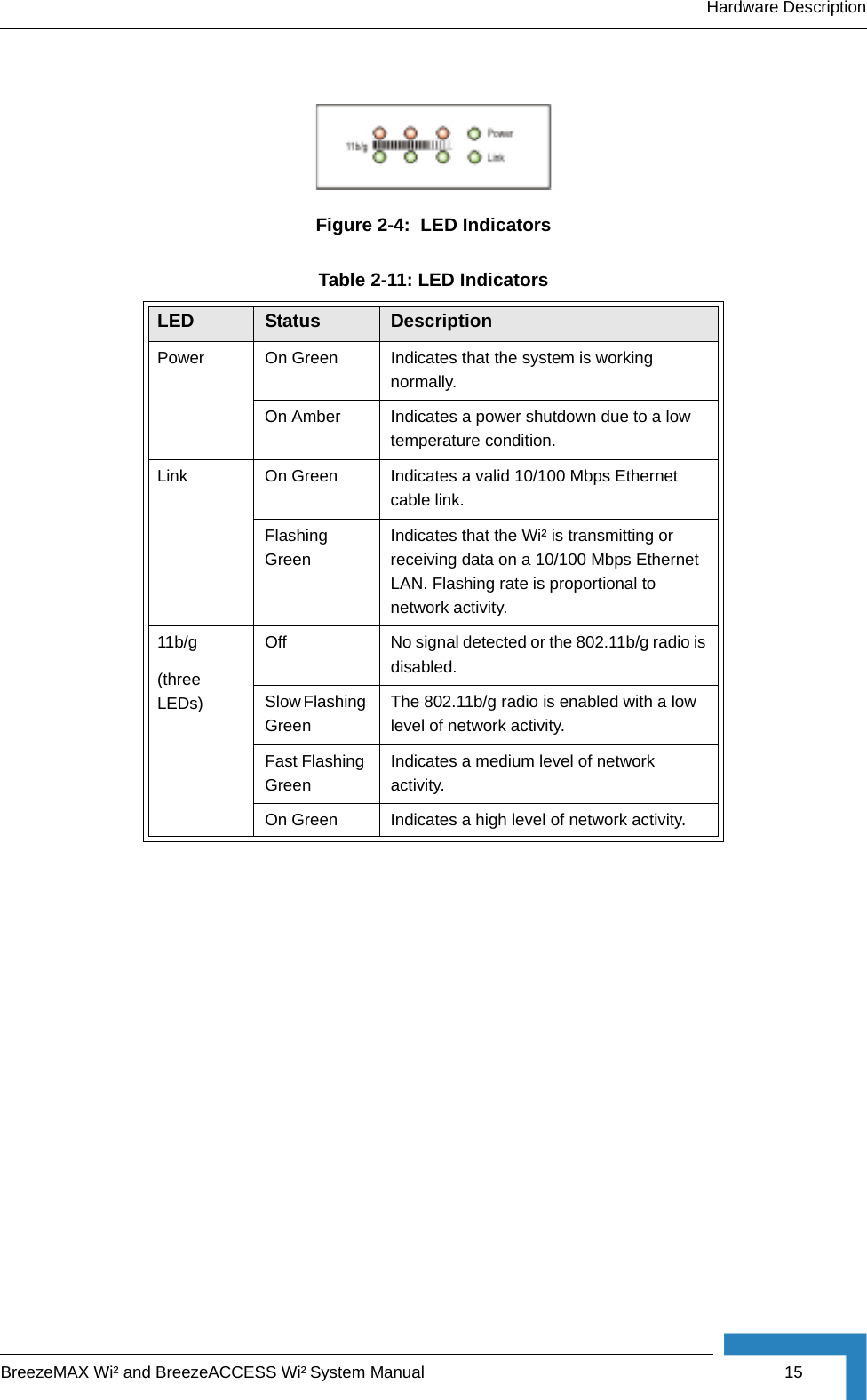
![114 OperationChapter 4 - System Configurationthe current security settings, use the show interface wireless a [0-3] or show interface wireless g [0-3] command (not shown in example).4.4.2.4 Configuring 802.1XIEEE 802.1X is a standard framework for network access control that uses a central RADIUS server for user authentication. This control feature prevents unauthorized access to the network by requiring an 802.1X client application to submit user credentials for authentication. The 802.1X standard uses the Extensible Authentication Protocol (EAP) to pass user credentials (either digital certificates, user names and passwords, or other) from the client to the RADIUS server. Client authentication is then verified on the RADIUS server before the access point grants client access to the network.The 802.1X EAP packets are also used to pass dynamic unicast session keys and static broadcast keys to wireless clients. Session keys are unique to each client and are used to encrypt and correlate traffic passing between a specific client and the access point. You can also enable broadcast key rotation, so the access point provides a dynamic broadcast key and changes it at a specified interval. Open the Security page, and click More for one of the VAP interfaces.Enterprise AP(config)#interface wireless g 210Enter Wireless configuration commands, one per line.Enterprise AP(if-wireless g)#vap 0Enterprise AP(if-wireless g: VAP[0])#auth wpa requiredData Encryption is set to Enabled.WPA2 Clients mode is set to Disabled.WPA Clients Mode is set to Required.WPA Multicast Cipher is set to TKIP.WPA Unicast Cipher can accept TKIP only.WPA Authentication is set to 802.1X Required. Enterprise AP(if-wireless g: VAP[0])#802.1X broadcast-key-refresh-rate 5Enterprise AP(if-wireless g: VAP[0])#802.1X session-key-refresh-rate 5Enterprise AP(if-wireless g: VAP[0])#802.1X session-timeout 300Enterprise AP(if-wireless g: VAP[0])#Figure 4-27: 802.1X Configuration](https://usermanual.wiki/Accton-Technology/OAP2611A/User-Guide-758212-Page-138.png)
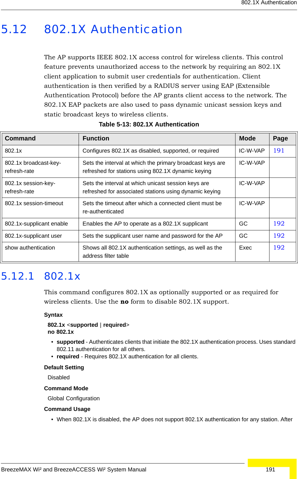
![Radio InterfaceBreezeMAX Wi² and BreezeACCESS Wi² System Manual 115You can enable 802.1X as optionally supported or as required to enhance the security of the wireless network. (Default: Disable)Disable: The AP does not support 802.1X authentication for any wireless client. After successful wireless association with the access point, each client is allowed to access the network.Supported: The access point supports 802.1X authentication only for clients initiating the 802.1X authentication process (i.e., the access point does not initiate 802.1X authentication). For clients initiating 802.1X, only those successfully authenticated are allowed to access the network. For those clients not initiating 802.1X, access to the network is allowed after successful wireless association with the access point. The 802.1X supported mode allows access for clients not using WPA or WPA2 security.Required: The access point enforces 802.1X authentication for all associated wireless clients. If 802.1X authentication is not initiated by a client, the AP will initiate authentication. Only those clients successfully authenticated with 802.1X are allowed to access the network.4.4.2.4.1 CLI Commands for 802.1X Authentication Use the 802.1X supported command from the VAP interface mode to enable 802.1X authentication. Set the session and broadcast key refresh rate, and the re-authentication timeout. To display the current settings, use the show interface wireless command from the Exec mode (not shown in the example).NOTEIf 802.1X is enabled on the access point, then RADIUS setup must be completed (see “RADIUS” on page 4-48.).Enterprise AP(if-wireless g: VAP[0])#802.1X supported 191Enterprise AP(if-wireless g: VAP[0])#802.1X broadcast-key-refresh-rate 5Enterprise AP(if-wireless g: VAP[0])#802.1X session-key-refresh-rate 5Enterprise AP(if-wireless g: VAP[0])#802.1X session-timeout 300Enterprise AP#](https://usermanual.wiki/Accton-Technology/OAP2611A/User-Guide-758212-Page-139.png)
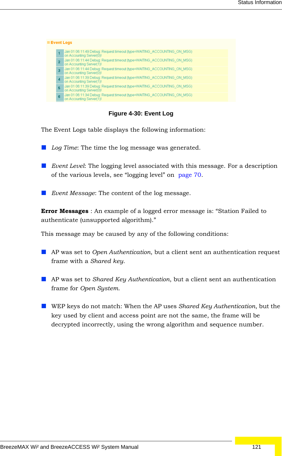
![120 OperationChapter 4 - System ConfigurationWEP Disabled – The client is not using Wired Equivalent Privacy (WEP) encryption keys.Dynamic – The client is using WiFi Protected Access (802.1X or pre-shared key mode) or using 802.1X authentication with dynamic keying.Static – The client is using static WEP keys for encryption.4.5.2.0.1 CLI Commands for Displaying Station StatusTo view status of clients currently associated with the access point, use the show station command from the Exec mode.4.5.3 Event LogsThe Event Logs window shows the log messages generated by the AP and stored in memory.Enterprise AP#show station 224Station Table Information===========================================================if-wireless G VAP [0] :802.11g Channel : AutoNo 802.11g Channel Stations.if-wireless G VAP [1] :802.11g Channel : AutoNo 802.11g Channel Stations.....No 802.11g Channel Stations.if-wireless G VAP [3] :802.11g Channel : AutoNo 802.11g Channel Stations.===========================================================Enterprise AP#](https://usermanual.wiki/Accton-Technology/OAP2611A/User-Guide-758212-Page-144.png)
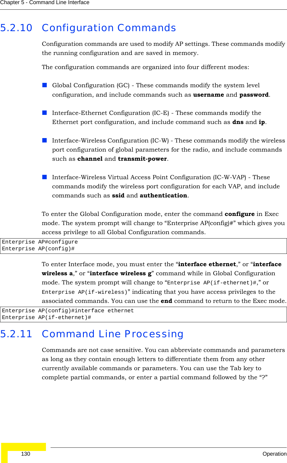
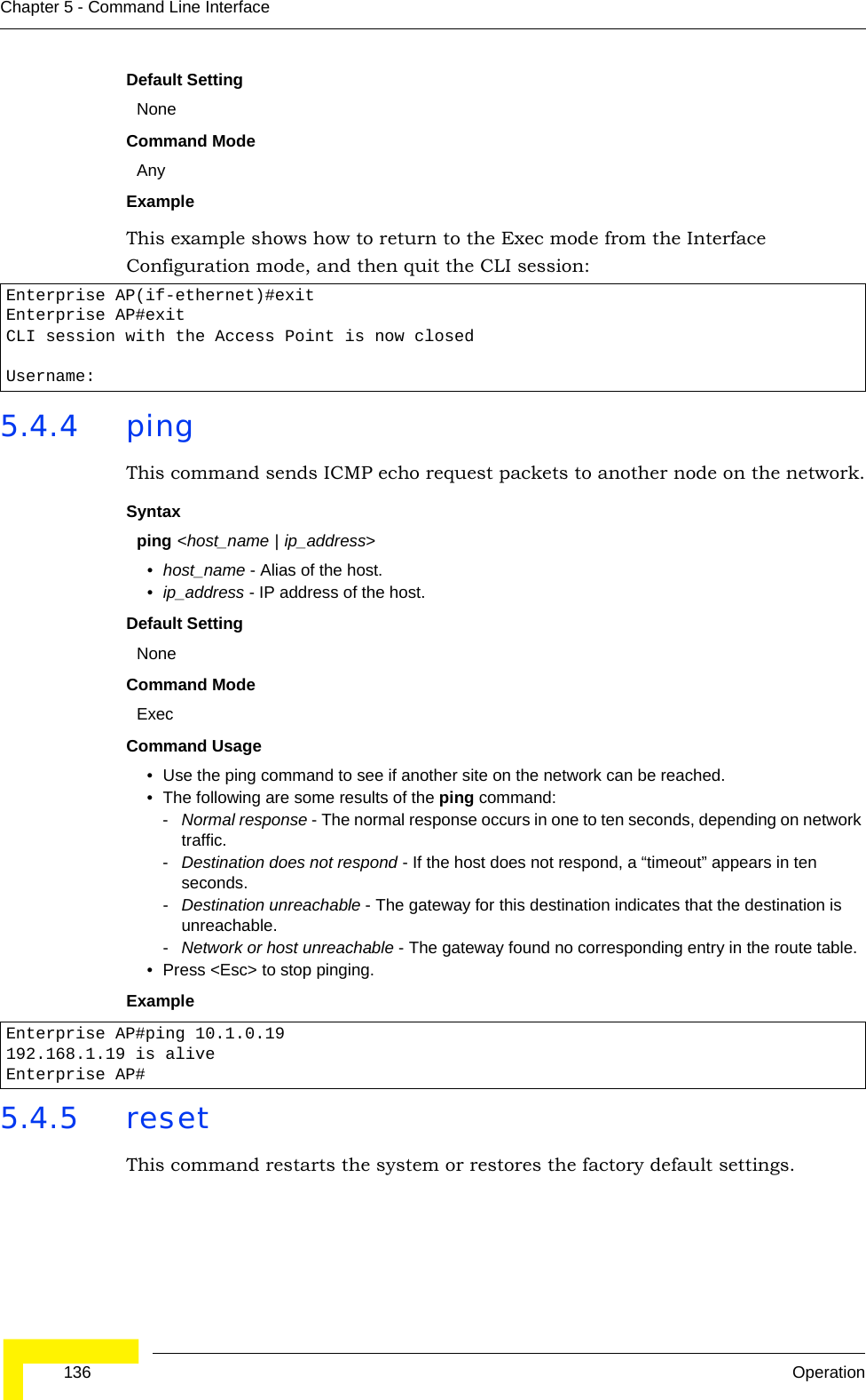
![Entering CommandsBreezeMAX Wi² and BreezeACCESS Wi² System Manual 1295.2.7 Using Command HistoryThe CLI maintains a history of commands that have been entered. You can scroll back through the history of commands by pressing the up arrow key. Any command displayed in the history list can be executed again, or first modified and then executed. Using the show history command displays a longer list of recently executed commands. 5.2.8 Understanding Command ModesThe command set is divided into Exec and Configuration classes. Exec commands generally display information on system status or clear statistical counters. Configuration commands, on the other hand, modify interface parameters or enable certain functions. These classes are further divided into different modes. Available commands depend on the selected mode. You can always enter a question mark “?” at the prompt to display a list of the commands available for the current mode. The command classes and associated modes are displayed in Table 5-1:5.2.9 Exec CommandsWhen you open a new console session on an AP, the system enters Exec command mode. Only a limited number of the commands are available in this mode. You can access all other commands only from the configuration mode. To access Exec mode, open a new console session with the user name admin. The command prompt displays as Enterprise AP# for Exec mode. Table 5-1: Command Classes and Associated ModesClass ModeExec PrivilegedConfiguration GlobalInterface-ethernetInterface-wirelessInterface-wireless-vapUsername: adminPassword: [system login password]Enterprise AP#](https://usermanual.wiki/Accton-Technology/OAP2611A/User-Guide-758212-Page-153.png)
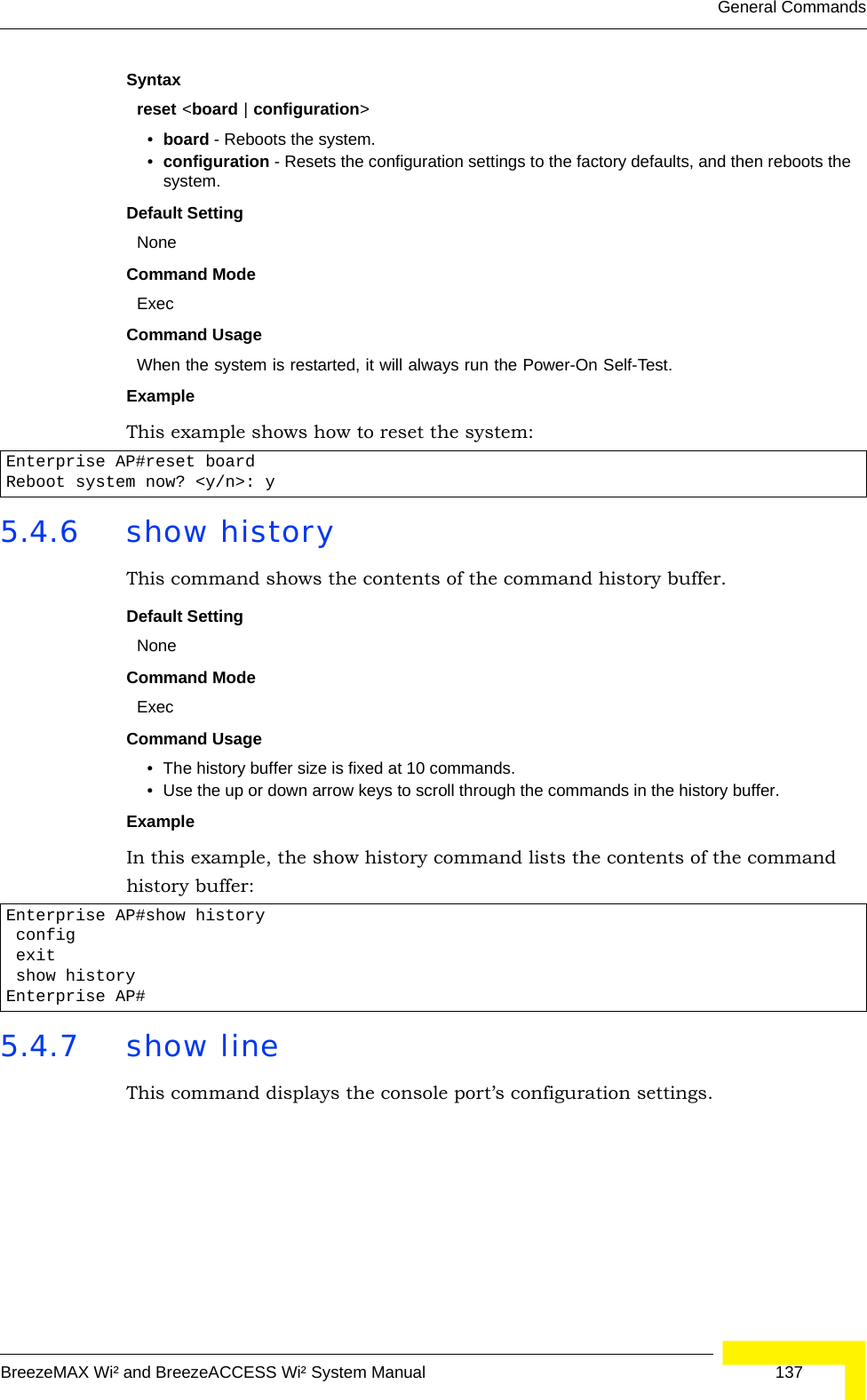
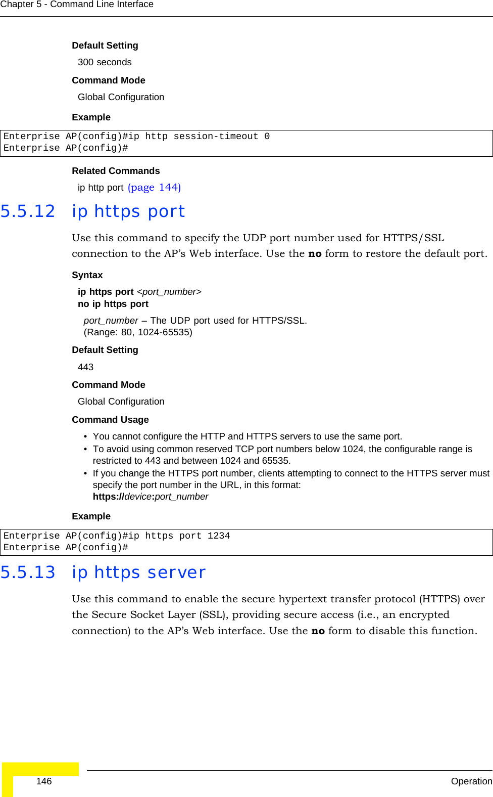
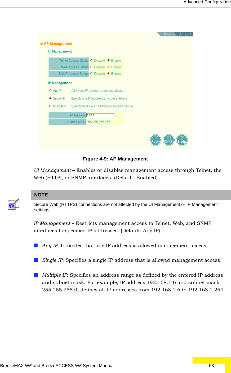
![System Management CommandsBreezeMAX Wi² and BreezeACCESS Wi² System Manual 147Syntax ip https serverno ip https serverDefault Setting EnabledCommand Mode Global ConfigurationCommand Usage • Both HTTP and HTTPS service can be enabled independently.• If you enable HTTPS, you must indicate this in the URL: https://device:port_number]• When you start HTTPS, the connection is established in this way:- The client authenticates the server using the server’s digital certificate.- The client and server negotiate a set of security protocols to use for the connection.- The client and server generate session keys for encrypting and decrypting data.• The client and server establish a secure encrypted connection.A padlock icon should appear in the status bar for Internet Explorer 5.x.Example 5.5.14 APmgmtIPThis command specifies the client IP addresses that are allowed management access to the AP through various protocols.SyntaxAPmgmtIP <multiple IP_address subnet_mask | single IP_address | any> •multiple - Adds IP addresses within a specifiable range to the SNMP, web and Telnet groups.•single - Adds an IP address to the SNMP, web and Telnet groups.•any - Allows any IP address access through SNMP, web and Telnet groups.•IP_address - Adds IP addresses to the SNMP, web and Telnet groups.•subnet_mask - Specifies a range of IP addresses allowed management access.Default SettingAll addressesCommand ModeGlobal ConfigurationCommand Usage• If anyone tries to access a management interface on the AP from an invalid address, the unit will reject the connection, enter an event message in the system log, and send a trap message to the trap manager.Enterprise AP(config)#ip https serverEnterprise AP(config)#CAUTIONSecure Web (HTTPS) connections are not affected by the UI Management or IP Management settings.](https://usermanual.wiki/Accton-Technology/OAP2611A/User-Guide-758212-Page-171.png)
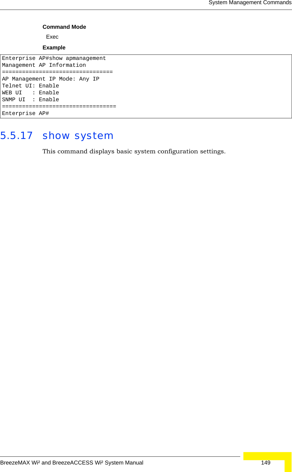
![148 OperationChapter 5 - Command Line Interface• IP address can be configured for SNMP, web and Telnet access respectively. Each of these groups can include up to five different sets of addresses, either individual addresses or address ranges.• When entering addresses for the same group (i.e., SNMP, web or Telnet), the AP will not accept overlapping address ranges. When entering addresses for different groups, the AP will accept overlapping address ranges.• You cannot delete an individual address from a specified range. You must delete the entire range, and reenter the addresses.• You can delete an address range just by specifying the start address, or by specifying both the start address and end address.ExampleThis example restricts management access to the indicated addresses.5.5.15 APmgmtUIThis command enables and disables management access to the AP through SNMP, Telnet and web interfaces.SyntaxAPmgmtUI <[SNMP | Telnet | Web] enable | disable>•SNMP - Specifies SNMP management access.•Telnet - Specifies Telnet management access.•Web - Specifies web based management access.-enable/disable - Enables or disables the selected management access method.Default SettingAll enabledCommand ModeGlobal ConfigurationExampleThis example restricts management access to the indicated addresses.5.5.16 show apmanagementThis command shows the AP management configuration, including the IP addresses of management stations allowed to access the AP, as well as the interface protocols which are open to management access.Enterprise AP(config)#apmgmtip multiple 192.168.1.50 255.255.255.0Enterprise AP(config)#CAUTIONSecure Web (HTTPS) connections are not affected by the UI Management or IP Management settings.Enterprise AP(config)#apmgmtui SNMP enableEnterprise AP(config)#](https://usermanual.wiki/Accton-Technology/OAP2611A/User-Guide-758212-Page-172.png)
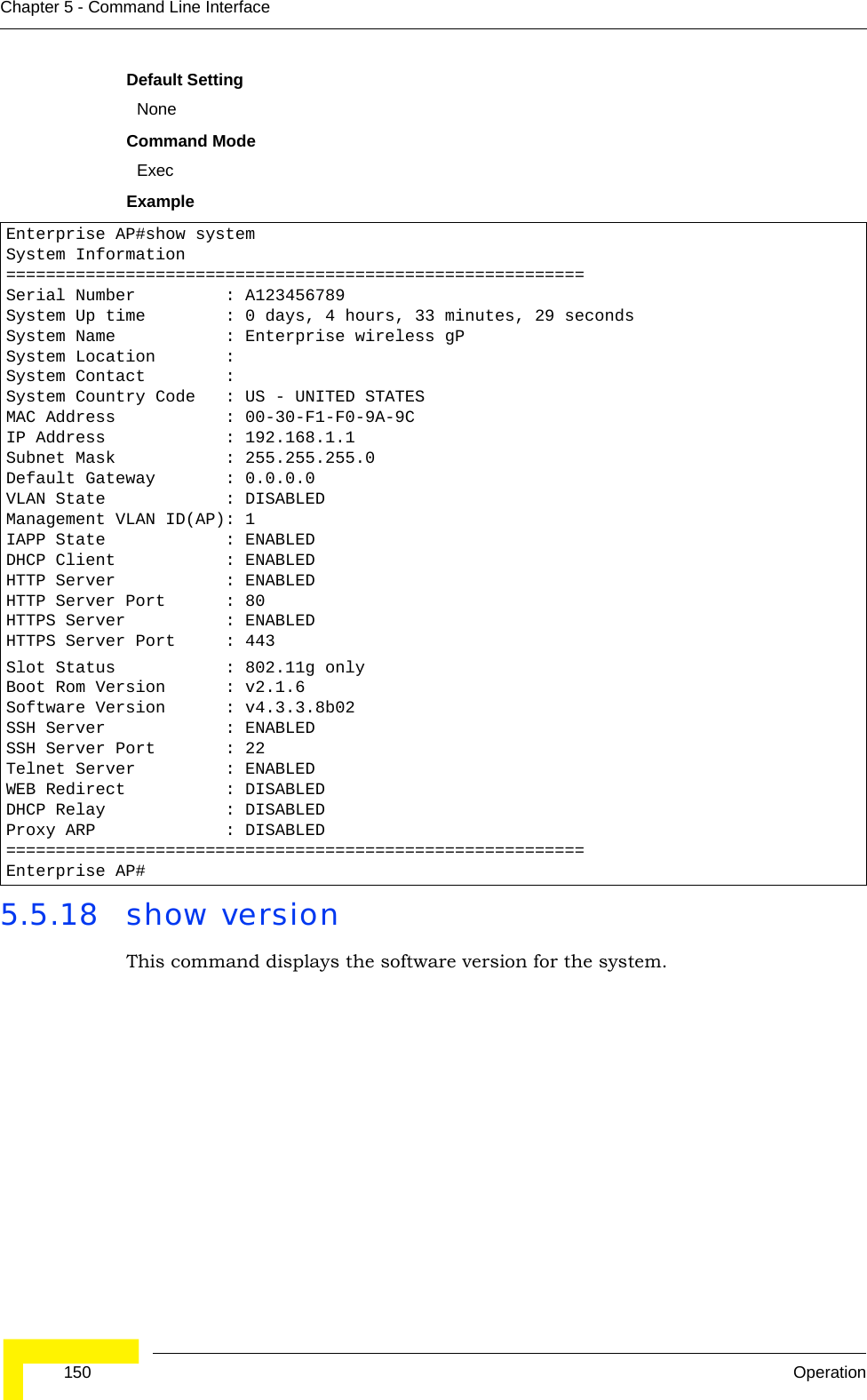
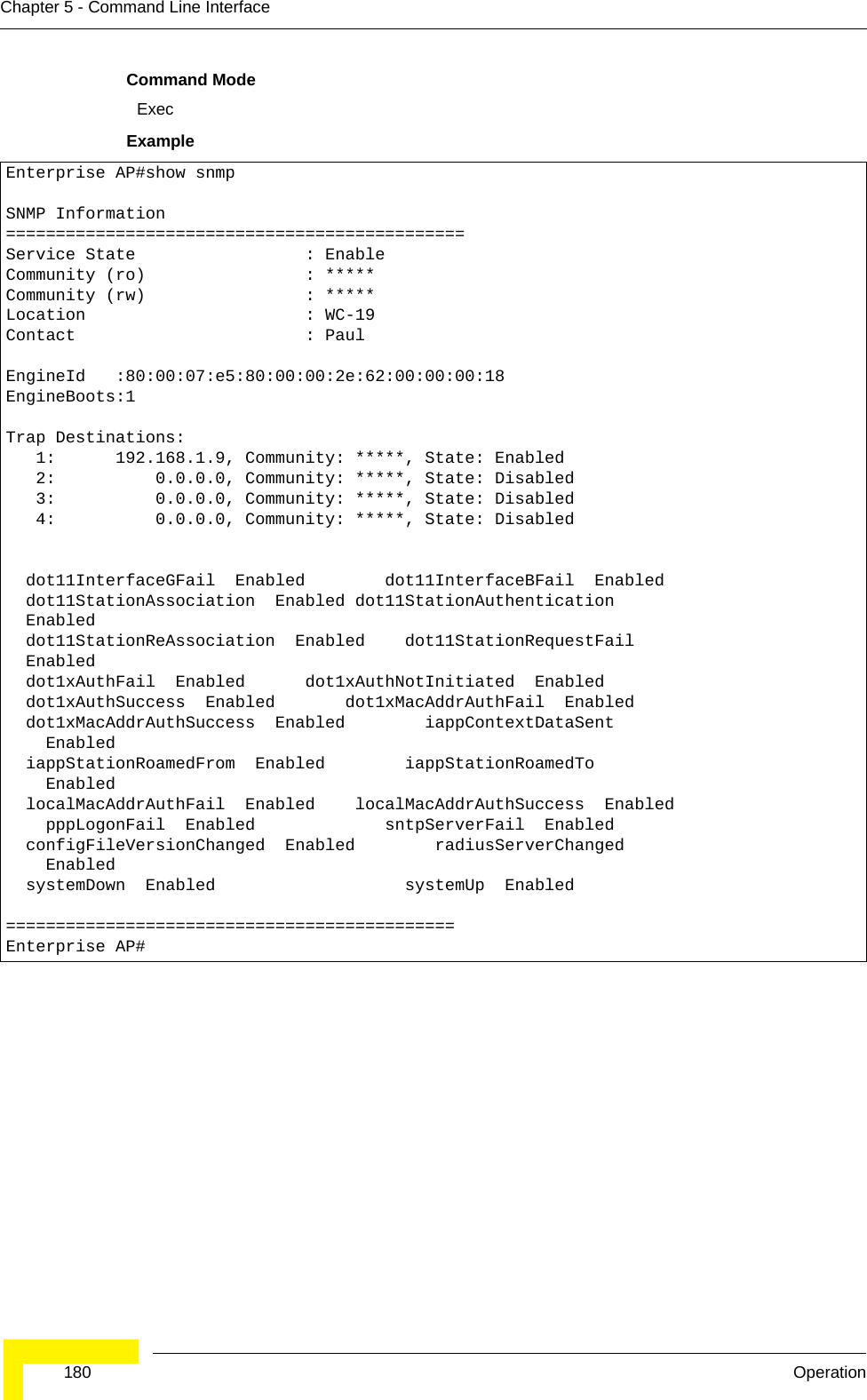
![System Management CommandsBreezeMAX Wi² and BreezeACCESS Wi² System Manual 155 dot11InterfaceGFail Enabled dot11InterfaceBFail Enabled dot11StationAssociation Enabled dot11StationAuthentication Enabled dot11StationReAssociation Enabled dot11StationRequestFail Enabled dot1xAuthFail Enabled dot1xAuthNotInitiated Enabled dot1xAuthSuccess Enabled dot1xMacAddrAuthFail Enabled dot1xMacAddrAuthSuccess Enabled iappContextDataSent Enabled iappStationRoamedFrom Enabled iappStationRoamedTo Enabled localMacAddrAuthFail Enabled localMacAddrAuthSuccess Enabled pppLogonFail Enabled sntpServerFail Enabled configFileVersionChanged Enabled radiusServerChanged Enabled systemDown Enabled systemUp Enabled=============================================SNTP Information===========================================================Service State : DisabledSNTP (server 1) IP : 137.92.140.80SNTP (server 2) IP : 192.43.244.18Current Time : 00 : 14, Jan 1st, 1970Time Zone : -5 (BOGOTA, EASTERN, INDIANA)Daylight Saving : Disabled===========================================================Station Table Information===========================================================if-wireless G VAP [0] : 802.11g Channel : AutoNo 802.11g Channel Stations....System Information==============================================================Serial Number : System Up time : 0 days, 0 hours, 16 minutes, 51 secondsSystem Name : Enterprise wireless gPSystem Location : System Contact : ContactSystem Country Code : 99 - NO_COUNTRY_SET MAC Address : 00-12-CF-05-B7-84IP Address : 192.168.0.151Subnet Mask : 255.255.255.0Default Gateway : 192.168.0.1VLAN State : DISABLEDManagement VLAN ID(AP): 1IAPP State : ENABLEDDHCP Client : ENABLEDHTTP Server : ENABLEDHTTP Server Port : 80HTTPS Server : ENABLEDHTTPS Server Port : 443Slot Status : Single bandBoot Rom Version : v2.1.6Software Version : v4.3.3.8b02](https://usermanual.wiki/Accton-Technology/OAP2611A/User-Guide-758212-Page-179.png)
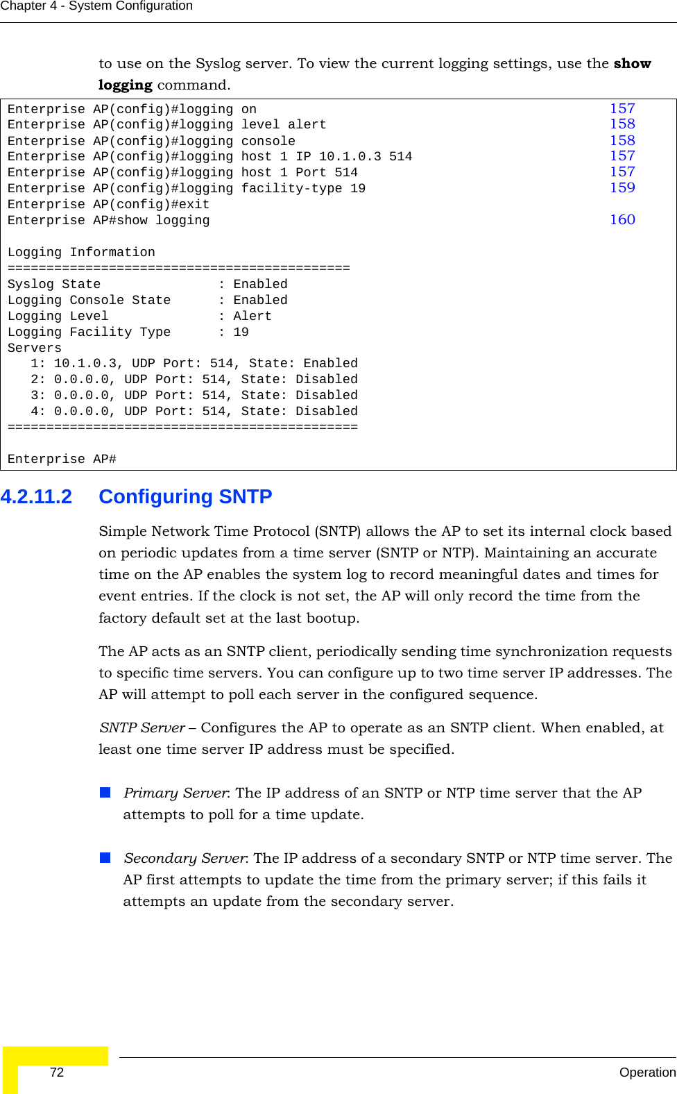
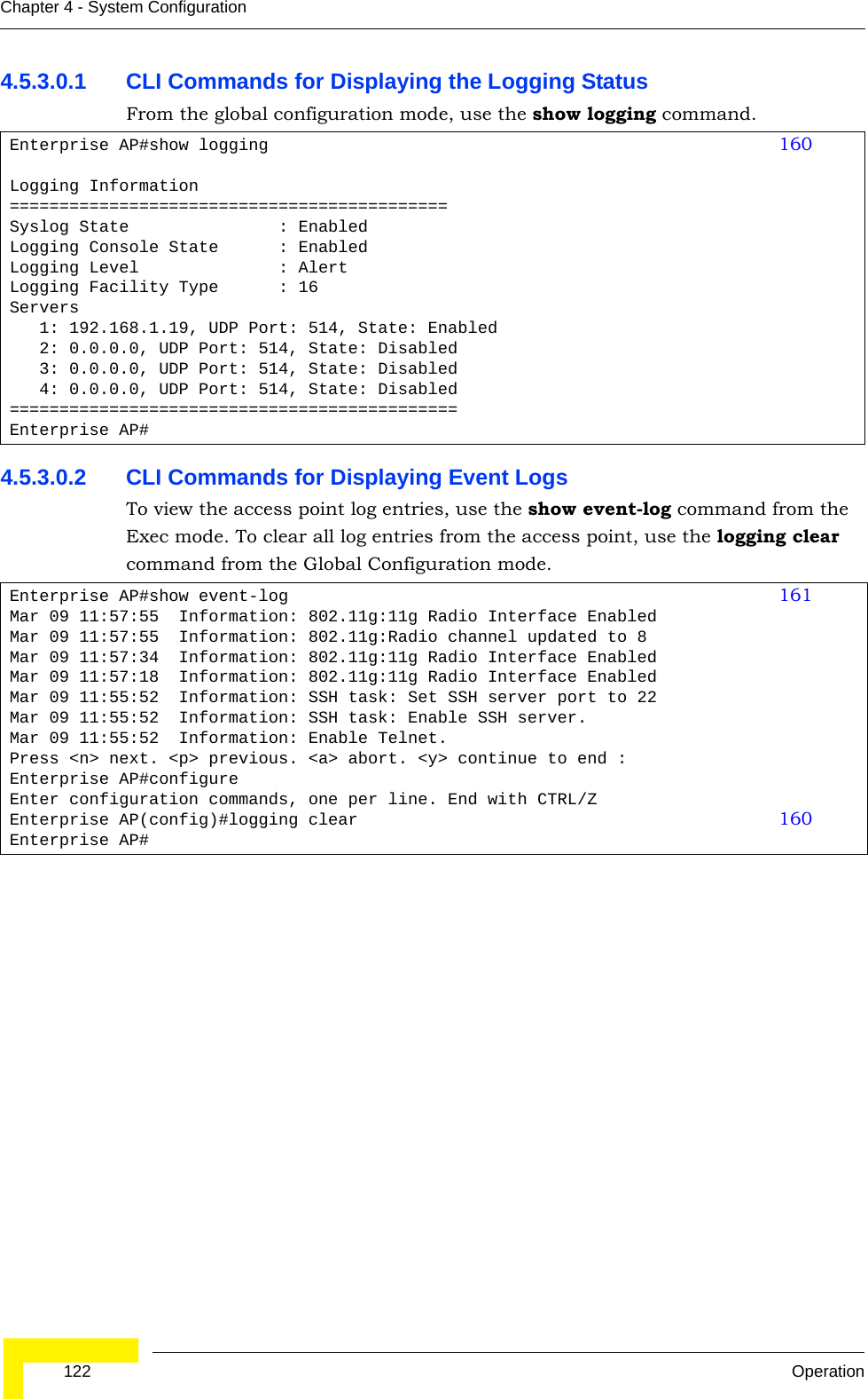
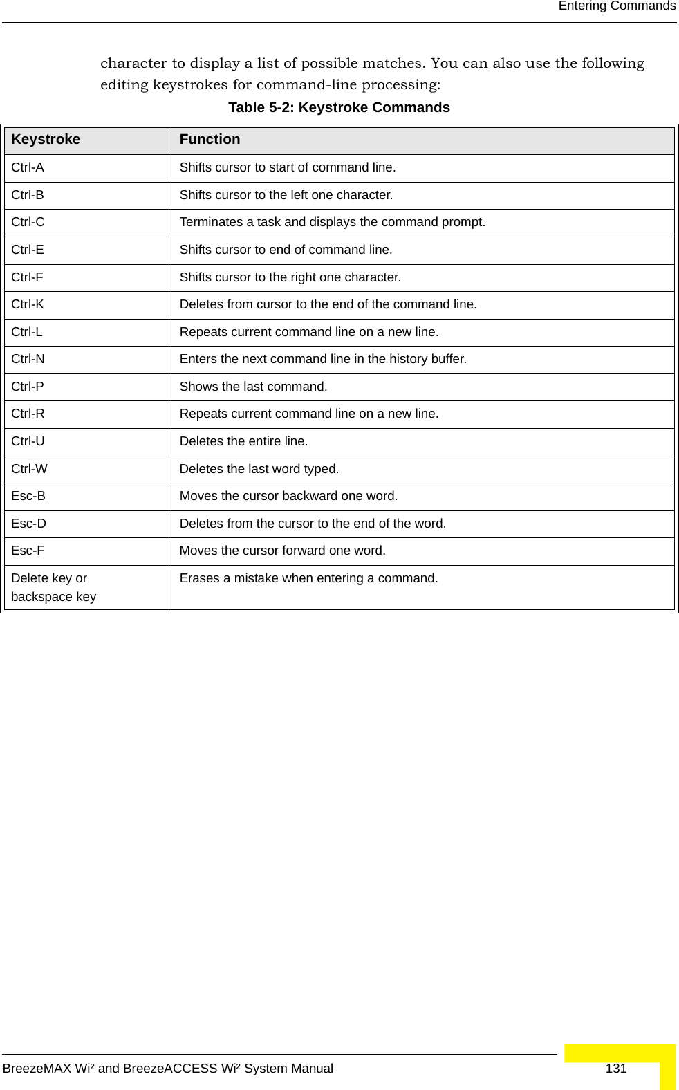
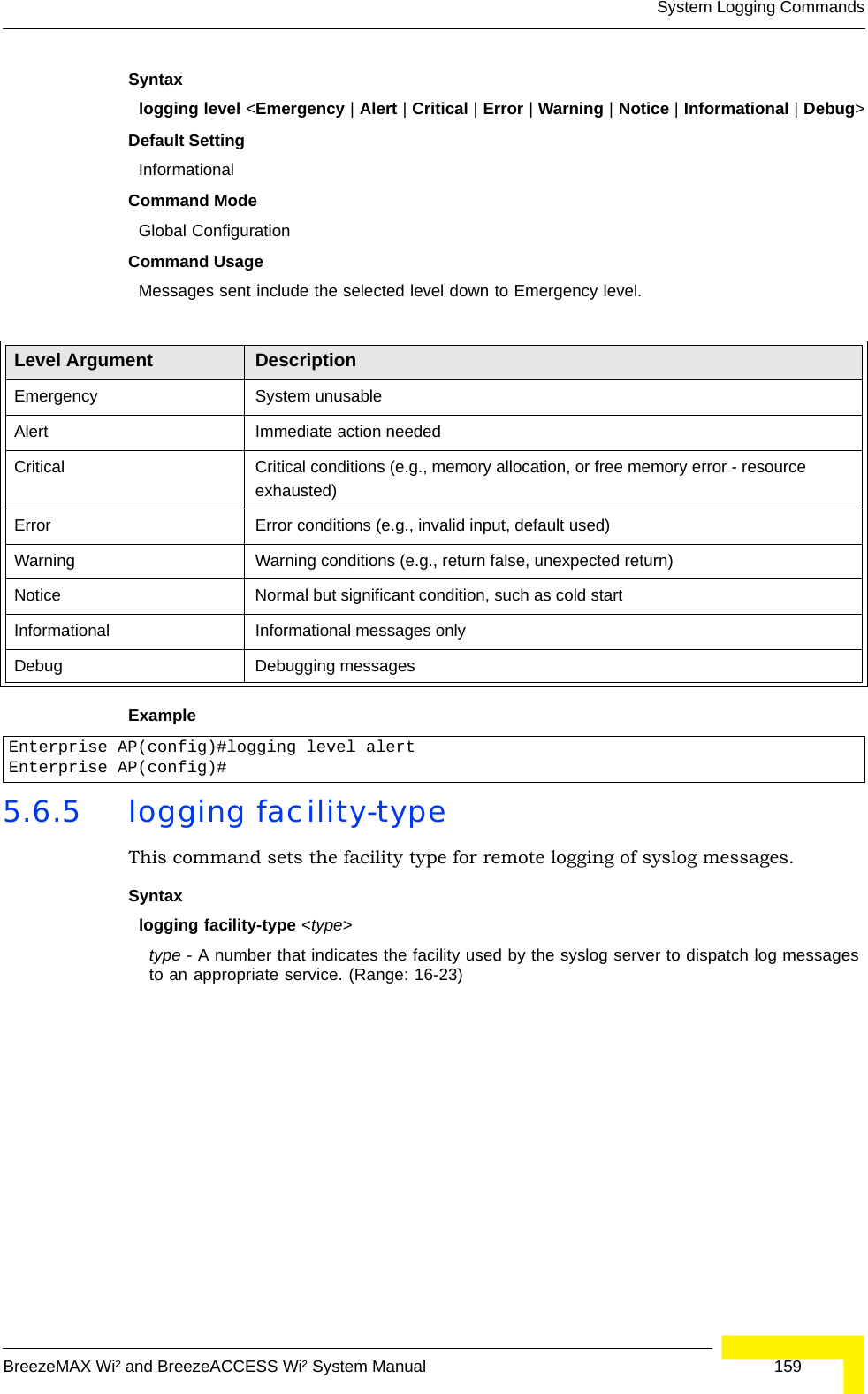
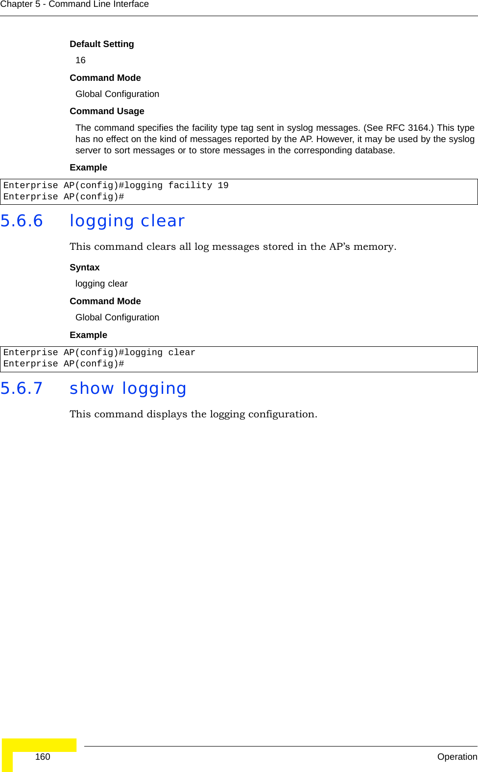
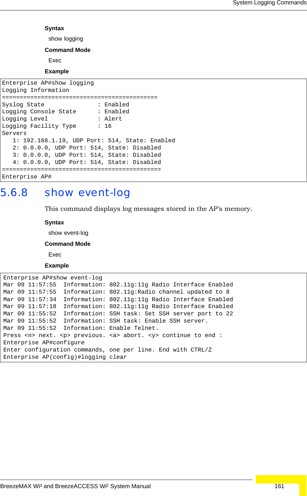
![System Logging CommandsBreezeMAX Wi² and BreezeACCESS Wi² System Manual 1575.6 System Logging CommandsThese commands are used to configure system logging on the AP.5.6.1 logging onThis command controls logging of error messages; i.e., sending debug or error messages to memory. The no form disables the logging process.Syntax[no] logging onDefault SettingDisabledCommand Mode Global ConfigurationCommand Usage The logging process controls error messages saved to memory. You can use the logging level command to control the type of error messages that are stored in memory. Example 5.6.2 logging hostThis command specifies syslog servers host that will receive logging messages. Use the no form to remove syslog server host.Table 5-7: System Logging CommandsCommand Function Mode Pagelogging on Controls logging of error messages GC 157logging host Adds a syslog server host IP address that will receive logging messages GC 157logging console Initiates logging of error messages to the console GC 158logging level Defines the minimum severity level for event logging GC 158logging facility-type Sets the facility type for remote logging of syslog messages GC 159logging clear Clears all log entries in AP memory GC 160show logging Displays the state of logging Exec 160show event-log Displays all log entries in AP memory Exec 161Enterprise AP(config)#logging onEnterprise AP(config)#](https://usermanual.wiki/Accton-Technology/OAP2611A/User-Guide-758212-Page-181.png)
![158 OperationChapter 5 - Command Line InterfaceSyntaxlogging host <1 | 2 | 3 | 4> <host_name | host_ip_address> [udp_port]no logging host <1 | 2 | 3 | 4>•1 - First syslog server.•2 - Second syslog server.•3 - Third syslog server.•4 - Fourth syslog server.•host_name - The name of a syslog server. (Range: 1-20 characters)•host_ip_address - The IP address of a syslog server.•udp_port - The UDP port used by the syslog server.Default Setting NoneCommand Mode Global ConfigurationExample 5.6.3 logging consoleThis command initiates logging of error messages to the console. Use the no form to disable logging to the console.Syntaxlogging consoleno logging consoleDefault Setting DisabledCommand Mode Global ConfigurationExample 5.6.4 logging levelThis command sets the minimum severity level for event logging.Enterprise AP(config)#logging host 1 10.1.0.3Enterprise AP(config)#Enterprise AP(config)#logging consoleEnterprise AP(config)#](https://usermanual.wiki/Accton-Technology/OAP2611A/User-Guide-758212-Page-182.png)
![166 OperationChapter 5 - Command Line Interface5.8 DHCP Relay CommandsDynamic Host Configuration Protocol (DHCP) can dynamically allocate an IP address and other configuration information to network clients that broadcast a request. To receive the broadcast request, the DHCP server would normally have to be on the same subnet as the client. However, when the AP’s DHCP relay agent is enabled, received client requests can be forwarded directly by the AP to a known DHCP server on another subnet. Responses from the DHCP server are returned to the AP, which then broadcasts them back to clients.5.8.1 dhcp-relay enableThis command enables the AP’s DHCP relay agent. Use the no form to disable the agent.Syntax[no] dhcp-relay enableDefault Setting DisabledCommand Mode Global ConfigurationCommand Usage • For the DHCP relay agent to function, the primary DHCP server must be configured using the dhcp-relay primary command. A secondary DHCP server does not need to be configured, but it is recommended.• If there is no response from the primary DHCP server, and a secondary server has been configured, the agent will then attempt to send DHCP requests to the secondary server.Example 5.8.2 dhcp-relayThis command configures the primary and secondary DHCP server addresses.Table 5-9: DHCP Relay CommandsCommand Function Mode Pagedhcp-relay enable Enables the DHCP relay agent GC 166dhcp-relay Sets the primary and secondary DHCP server address GC 166show dhcp-relay Shows current DHCP relay configuration settings Exec 167Enterprise AP(config)#dhcp-relay enableEnterprise AP(config)#](https://usermanual.wiki/Accton-Technology/OAP2611A/User-Guide-758212-Page-190.png)
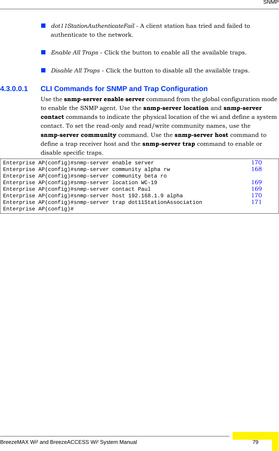
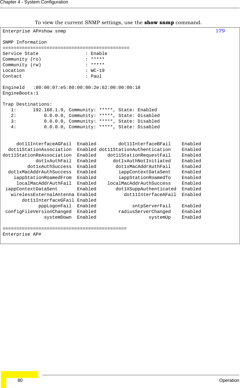
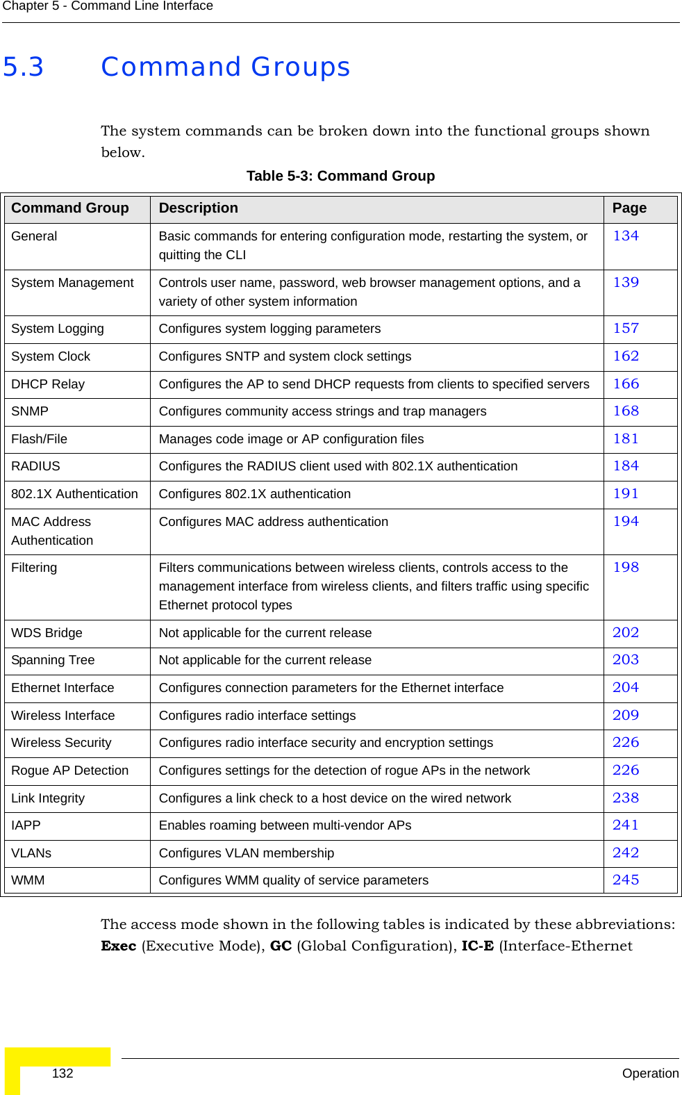
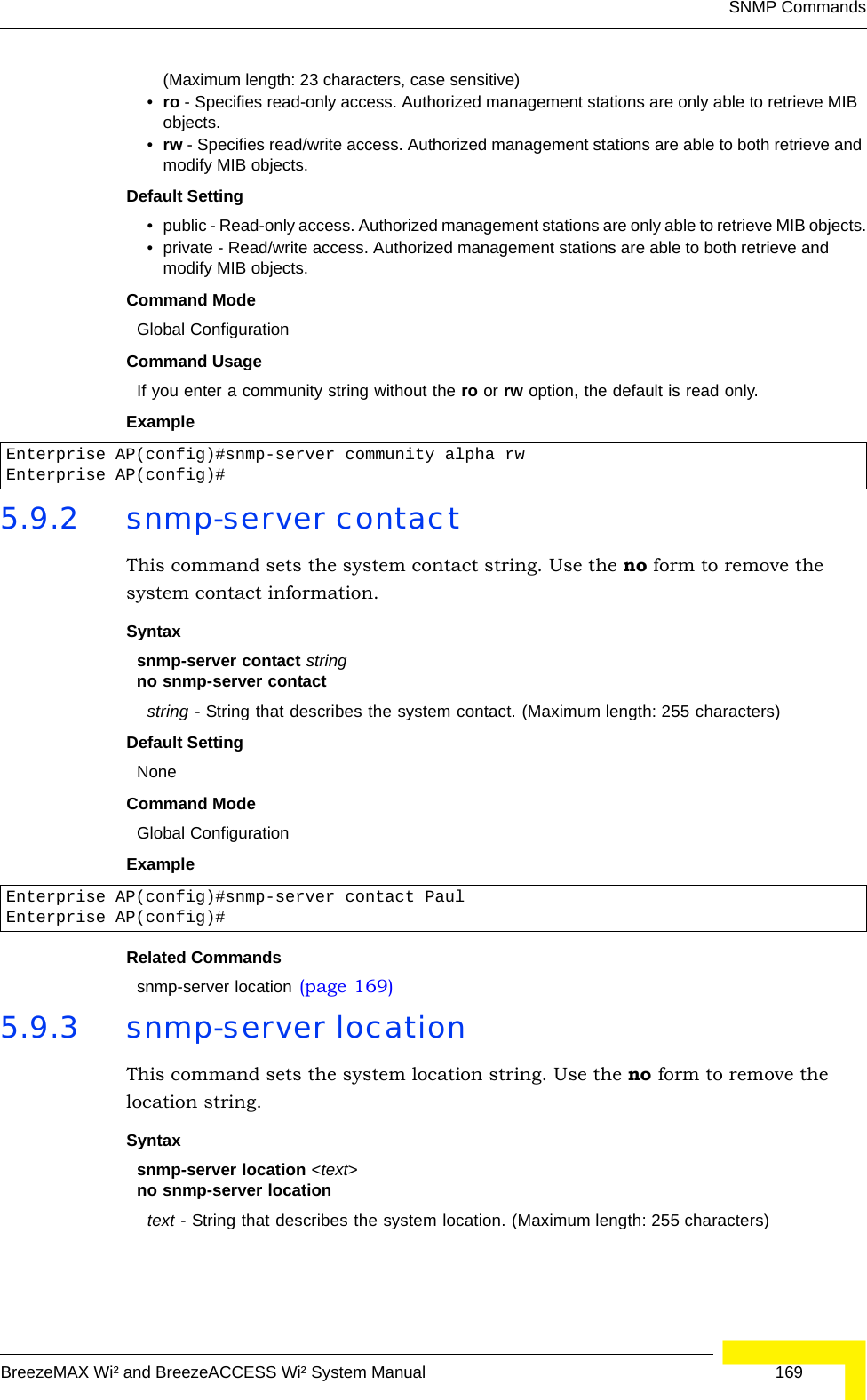
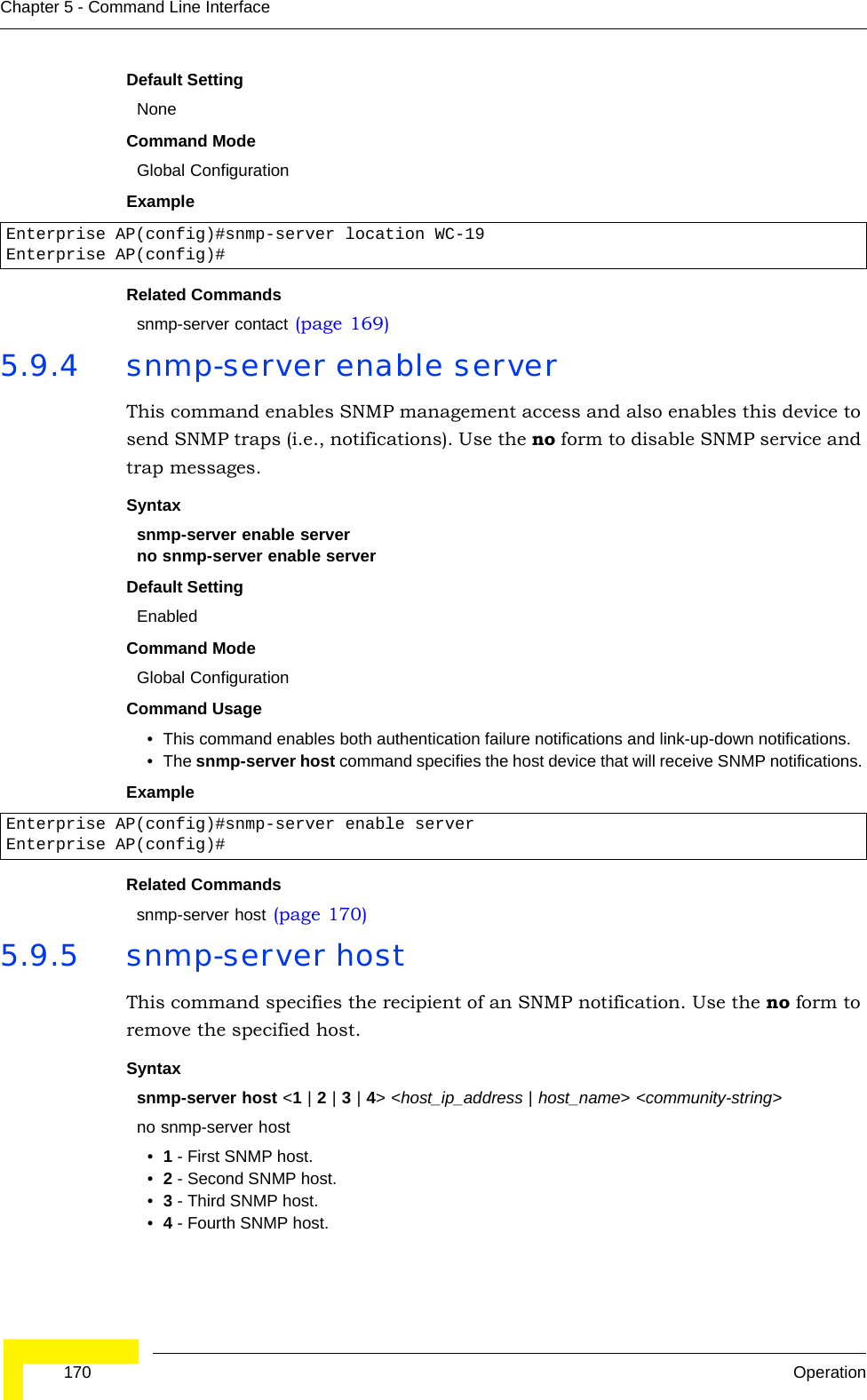
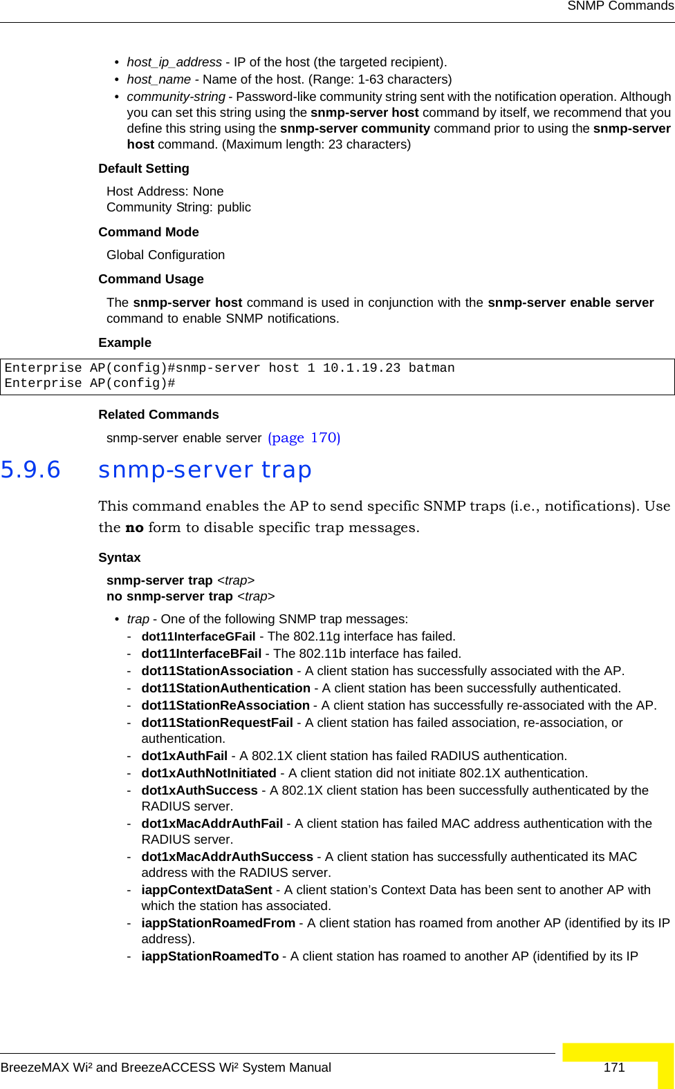
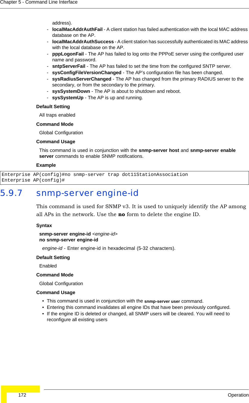
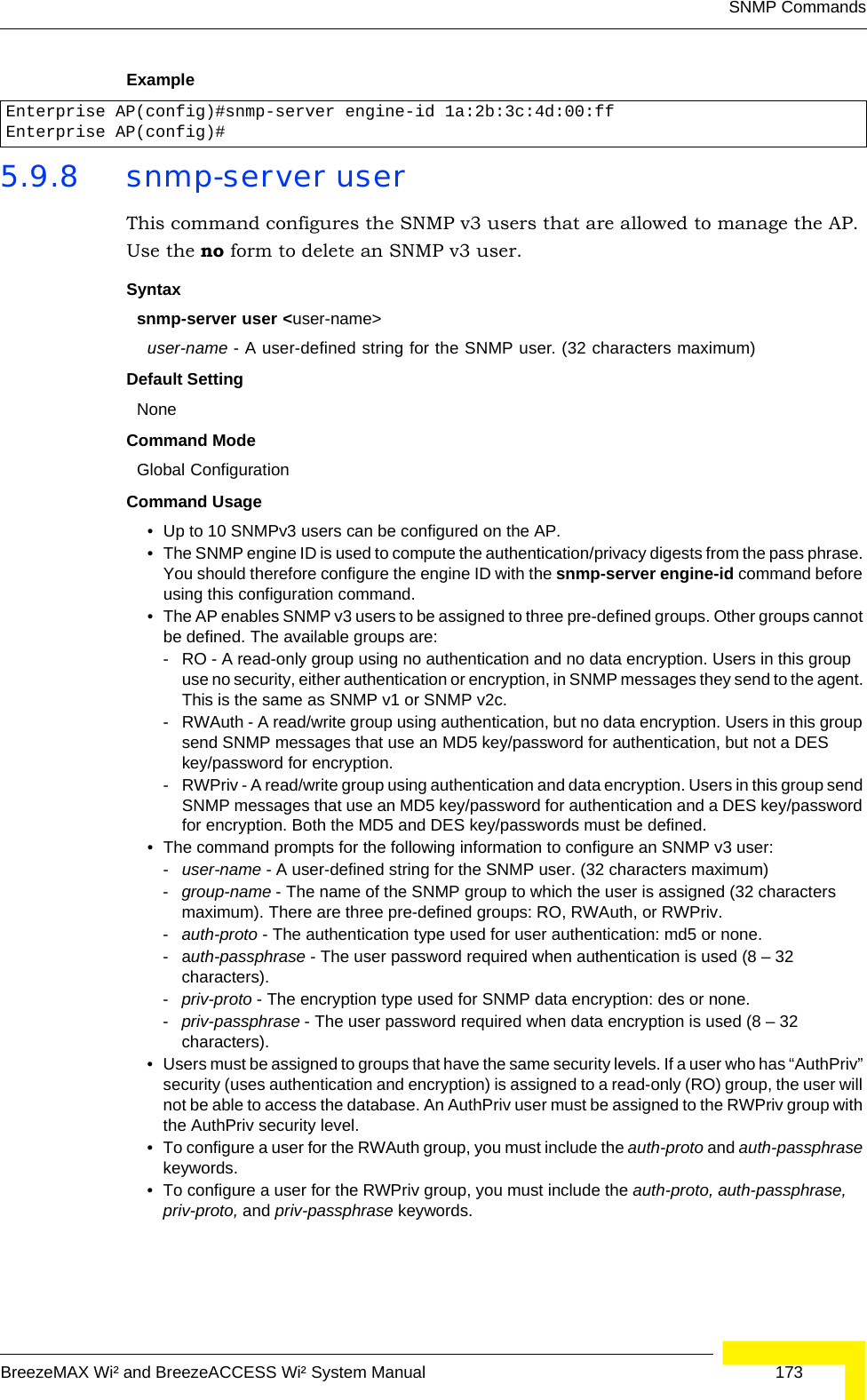
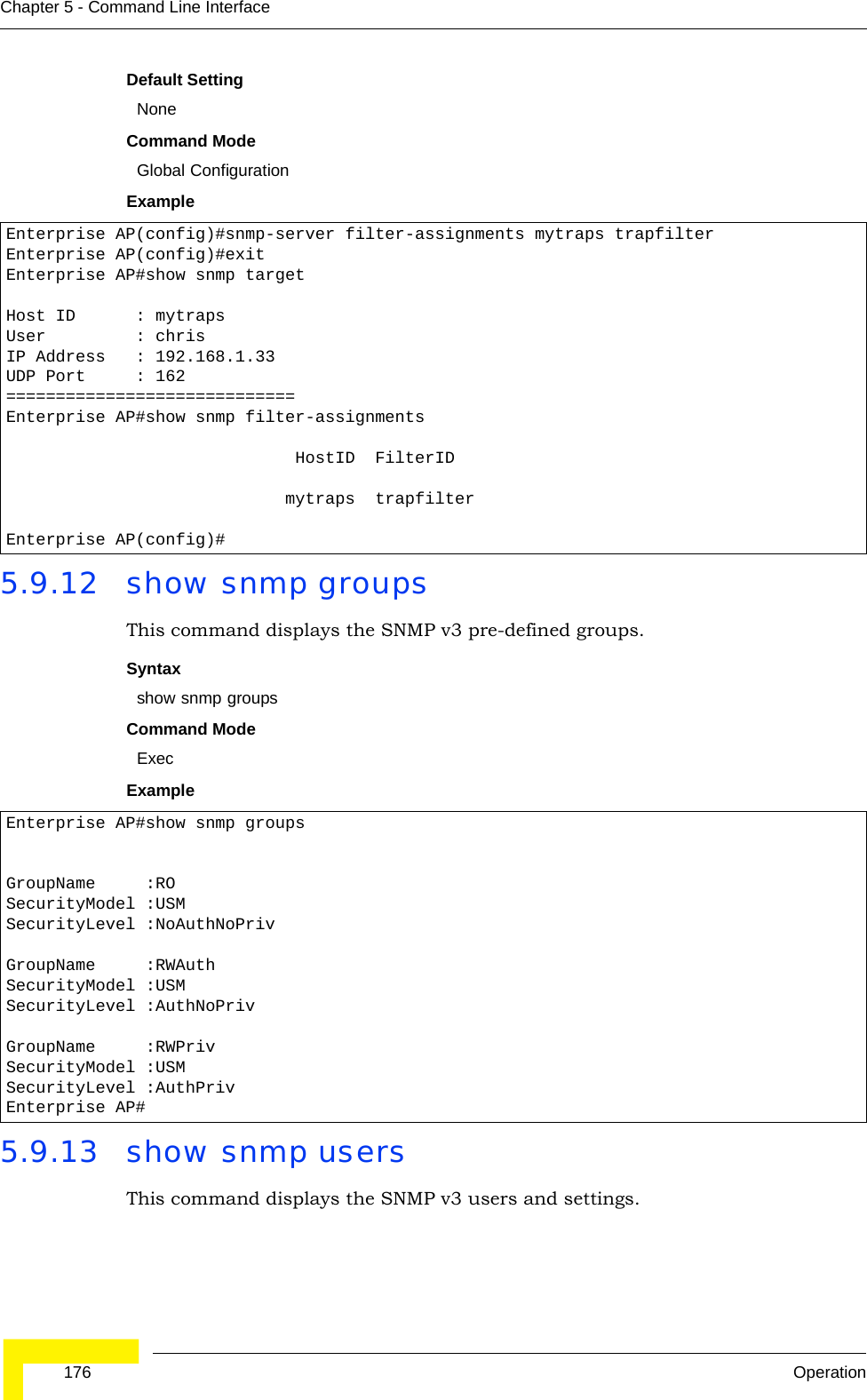
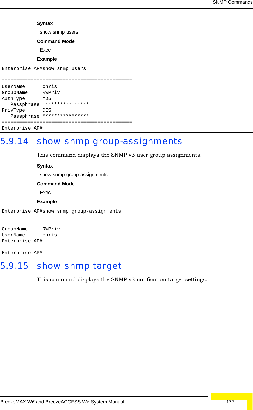
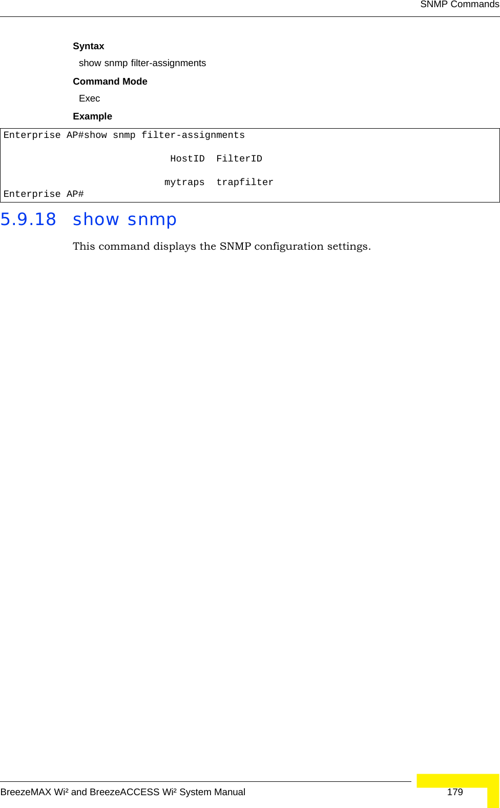
![168 OperationChapter 5 - Command Line Interface5.9 SNMP CommandsControls access to this AP from management stations using the Simple Network Management Protocol (SNMP), as well as the hosts that will receive trap messages.5.9.1 snmp-server communityThis command defines the community access string for the Simple Network Management Protocol. Use the no form to remove the specified community string.Syntaxsnmp-server community string [ro | rw]no snmp-server community string•string - Community string that acts like a password and permits access to the SNMP protocol. Table 5-10: SNMP CommandsCommand Function Mode Pagesnmp-server community Sets up the community access string to permit access to SNMP commands GC 168snmp-server contact Sets the system contact string GC 169snmp-server location Sets the system location string GC 169snmp-server enable server Enables SNMP service and traps GC 170snmp-server host Specifies the recipient of an SNMP notification operation GC 170snmp-server trap Enables specific SNMP notifications GC 171snmp-server engine id Sets the engine ID for SNMP v3 GC 172snmp-server user Sets the name of the SNMP v3 user GC 173snmp-server targets Configures SNMP v3 notification targets GC 174snmp-server filter Configures SNMP v3 notification filters GC 174snmp-server filter-assignmentsAssigns SNMP v3 notification filters to targets GC 175show snmp groups Displays the pre-defined SNMP v3 groups Exec 176show snmp users Displays SNMP v3 user settings Exec 176show snmp group-assignmentsDisplays the assignment of users to SNMP v3 groups Exec 177show snmp target Displays the SNMP v3 notification targets Exec 177show snmp filter Displays the SNMP v3 notification filters Exec 178show snmp filter-assignments Displays the SNMP v3 notification filter assignments Exec 178show snmp Displays the status of SNMP communications Exec 179](https://usermanual.wiki/Accton-Technology/OAP2611A/User-Guide-758212-Page-192.png)
![174 OperationChapter 5 - Command Line InterfaceExample 5.9.9 snmp-server targetsThis command configures SNMP v3 notification targets. Use the no form to delete an SNMP v3 target.Syntaxsnmp-server targets <target-id> <ip-addr> <sec-name> [version {3}] [udp-port {port-number}] [notification-type {TRAP}]no snmp-server targets <target-id>•target-id - A user-defined name that identifies a receiver of SNMP notifications. (Maximum length: 32 characters)•ip-addr - Specifies the IP address of the management station to receive notifications.•sec-name - The defined SNMP v3 user name that is to receive notifications.•version - The SNMP version of notifications. Currently only version 3 is supported in this command.•udp-port - The UDP port that is used on the receiving management station for notifications.•notification-type - The type of notification that is sent. Currently only TRAP is supported.Default Setting NoneCommand Mode Global ConfigurationCommand Usage • The AP supports up to 10 SNMP v3 target IDs.• The SNMP v3 user name that is specified in the target must first be configured using the snmp-server user command.Example 5.9.10 snmp-server filterThis command configures SNMP v3 notification filters. Use the no form to delete an SNMP v3 filter or remove a subtree from a filter.Enterprise AP(config)#snmp-server user User Name<1-32> :chrisGroup Name<1-32> :RWPrivAuthtype(md5,<cr>none):md5Passphrase<8-32>:a good secretPrivacy(des,<cr>none) :desPassphrase<8-32>:a very good secretEnterprise AP(config)#Enterprise AP(config)#snmp-server targets mytraps 192.168.1.33 chrisEnterprise AP(config)#](https://usermanual.wiki/Accton-Technology/OAP2611A/User-Guide-758212-Page-198.png)
![SNMP CommandsBreezeMAX Wi² and BreezeACCESS Wi² System Manual 175Syntaxsnmp-server filter <filter-id> <include | exclude> <subtree> [mask {mask}]no snmp-server filter <filter-id> [subtree]•filter-id - A user-defined name that identifies an SNMP v3 notification filter. (Maximum length: 32 characters)•include - Defines a filter type that includes objects in the MIB subtree.•exclude - Defines a filter type that excludes objects in the MIB subtree.•subtree - The part of the MIB subtree that is to be filtered.•mask - An optional hexadecimal value bit mask to define objects in the MIB subtree. Default Setting NoneCommand Mode Global ConfigurationCommand Usage • The AP allows up to 10 notification filters to be created. Each filter can be defined by up to 20 MIB subtree ID entries.• Use the command more than once with the same filter ID to build a filter that includes or excludes multiple MIB objects. Note that the filter entries are applied in the sequence that they are defined.• The MIB subtree must be defined in the form “.1.3.6.1” and always start with a “.”.• The mask is a hexadecimal value with each bit masking the corresponding ID in the MIB subtree. A “1” in the mask indicates an exact match and a “0” indicates a “wild card.” For example, a mask value of 0xFFBF provides a bit mask “1111 1111 1011 1111.” If applied to the subtree 1.3.6.1.2.1.2.2.1.1.23, the zero corresponds to the 10th subtree ID. When there are more subtree IDs than bits in the mask, the mask is padded with ones.Example 5.9.11 snmp-server filter-assignmentsThis command assigns SNMP v3 notification filters to targets. Use the no form to remove an SNMP v3 filter assignment.Syntaxsnmp-server filter-assignments <target-id> <filter-id> no snmp-server filter-assignments <target-id> •target-id - A user-defined name that identifies a receiver of SNMP notifications. (Maximum length: 32 characters)•filter-id - A user-defined name that identifies an SNMP v3 notification filter. (Maximum length: 32 characters)Enterprise AP(config)#snmp-server filter trapfilter include .1Enterprise AP(config)#snmp-server filter trapfilter exclude .1.3.6.1.2.1.2.2.1.1.23](https://usermanual.wiki/Accton-Technology/OAP2611A/User-Guide-758212-Page-199.png)
![178 OperationChapter 5 - Command Line InterfaceSyntaxshow snmp targetCommand Mode ExecExample 5.9.16 show snmp filterThis command displays the SNMP v3 notification filter settings.Syntaxshow snmp filter [filter-id] •filter-id - A user-defined name that identifies an SNMP v3 notification filter. (Maximum length: 32 characters)Command Mode ExecExample 5.9.17 show snmp filter-assignmentsThis command displays the SNMP v3 notification filter assignments.Enterprise AP#show snmp targetHost ID : mytrapsUser : chrisIP Address : 192.168.1.33UDP Port : 162=============================Enterprise AP#Enterprise AP#show snmp filterFilter: trapfilter Type: include Subtree: iso.3.6.1.2.1.2.2.1 Type: exclude Subtree: iso.3.6.1.2.1.2.2.1.1.23=============================Enterprise AP#](https://usermanual.wiki/Accton-Technology/OAP2611A/User-Guide-758212-Page-202.png)
![182 OperationChapter 5 - Command Line InterfaceSyntaxcopy <ftp | tftp> filecopy config <ftp | tftp>•ftp - Keyword that allows you to copy to/from an FTP server.•tftp - Keyword that allows you to copy to/from a TFTP server.•file - Keyword that allows you to copy to/from a flash memory file. •config - Keyword that allows you to upload the configuration file from flash memory. Default Setting NoneCommand Mode ExecCommand Usage • The system prompts for data required to complete the copy command. • Only a configuration file can be uploaded to an FTP/TFTP server, but every type of file can be downloaded to the AP.•The destination file name should not contain slashes (\ or /), the leading letter of the file name should not be a period (.), and the maximum length for file names on the FTP/TFTP server is 255 characters or 32 characters for files on the AP. (Valid characters: A-Z, a-z, 0-9, “.”, “-”, “_”)• Due to the size limit of the flash memory, the AP supports only two operation code files.• The system configuration file must be named “syscfg” in all copy commands.Example The following example shows how to upload the configuration settings to a file on the TFTP server:The following example shows how to download a configuration file: 5.10.3 deleteThis command deletes a file or image.Syntaxdelete <filename>filename - Name of the configuration file or image name.Enterprise AP#copy config tftpTFTP Source file name:syscfgTFTP Server IP:192.168.1.19Enterprise AP#Enterprise AP#copy tftp file1. Application image2. Config file3. Boot block imageSelect the type of download<1,2,3>: [1]:2TFTP Source file name:syscfgTFTP Server IP:192.168.1.19Enterprise AP#](https://usermanual.wiki/Accton-Technology/OAP2611A/User-Guide-758212-Page-206.png)
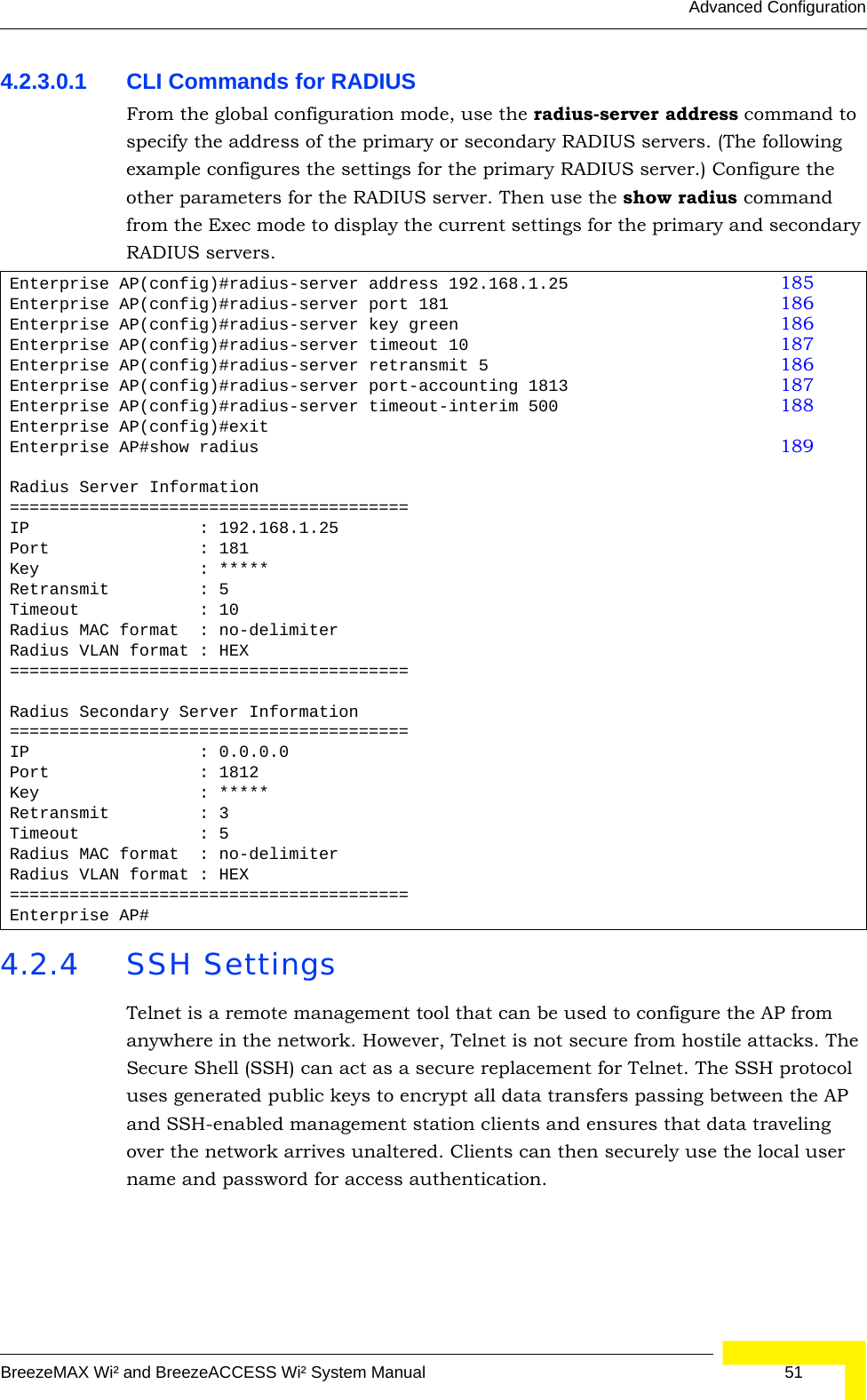
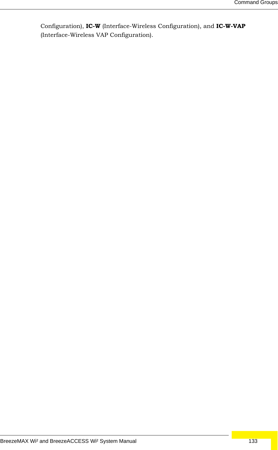
![RADIUS ClientBreezeMAX Wi² and BreezeACCESS Wi² System Manual 1855.11 RADIUS ClientRemote Authentication Dial-in User Service (RADIUS) is a logon authentication protocol that uses software running on a central server to control access for RADIUS-aware devices to the network. An authentication server contains a database of credentials, such as users names and passwords, for each wireless client that requires access to the AP.5.11.1 radius-server addressThis command specifies the primary and secondary RADIUS servers. Syntaxradius-server [secondary] address <host_ip_address | host_name>•secondary - Secondary server.•host_ip_address - IP address of server.•host_name - Host name of server. (Range: 1-20 characters)Table 5-12: RADIUS ClientCommand Function Mode Pageradius-server address Specifies the RADIUS server GC 185radius-server port Sets the RADIUS server network port GC 186radius-server key Sets the RADIUS encryption key GC 186radius-server retransmit Sets the number of retries GC 186radius-server timeout Sets the interval between sending authentication requestsGC 187radius-server port-accounting Sets the RADIUS Accounting server network port GC 187radius-server timeout-interim Sets the interval between transmitting accounting updates to the RADIUS serverGC 188radius-server radius-mac-formatSets the format for specifying MAC addresses on the RADIUS serverGC 188radius-server vlan-format Sets the format for specifying VLAN IDs on the RADIUS serverGC 189show radius Shows the current RADIUS settings Exec 189](https://usermanual.wiki/Accton-Technology/OAP2611A/User-Guide-758212-Page-209.png)
![186 OperationChapter 5 - Command Line InterfaceDefault Setting NoneCommand Mode Global ConfigurationExample 5.11.2 radius-server portThis command sets the RADIUS server network port. Syntaxradius-server [secondary] port <port_number>•secondary - Secondary server.•port_number - RADIUS server UDP port used for authentication messages. (Range: 1024-65535)Default Setting 1812Command Mode Global ConfigurationExample 5.11.3 radius-server keyThis command sets the RADIUS encryption key. Syntax radius-server [secondary] key <key_string>•secondary - Secondary server.•key_string - Encryption key used to authenticate logon access for client. Do not use blank spaces in the string. (Maximum length: 20 characters)Default Setting DEFAULTCommand Mode Global ConfigurationExample 5.11.4 radius-server retransmitThis command sets the number of retries. Enterprise AP(config)#radius-server address 192.168.1.25Enterprise AP(config)#Enterprise AP(config)#radius-server port 181Enterprise AP(config)#Enterprise AP(config)#radius-server key greenEnterprise AP(config)#](https://usermanual.wiki/Accton-Technology/OAP2611A/User-Guide-758212-Page-210.png)
![RADIUS ClientBreezeMAX Wi² and BreezeACCESS Wi² System Manual 187Syntaxradius-server [secondary] retransmit number_of_retries•secondary - Secondary server.•number_of_retries - Number of times the AP will try to authenticate logon access via the RADIUS server. (Range: 1 - 30)Default Setting 3Command Mode Global ConfigurationExample 5.11.5 radius-server timeoutThis command sets the interval between transmitting authentication requests to the RADIUS server. Syntax radius-server [secondary] timeout number_of_seconds•secondary - Secondary server.•number_of_seconds - Number of seconds the AP waits for a reply before resending a request. (Range: 1-60)Default Setting 5Command Mode Global ConfigurationExample 5.11.6 radius-server port-accountingThis command sets the RADIUS Accounting server network port. Syntaxradius-server [secondary] port-accounting <port_number>•secondary - Secondary server. If secondary is not specified, then the AP assumes you are configuring the primary RADIUS server.•port_number - RADIUS Accounting server UDP port used for accounting messages. (Range: 0 or 1024-65535)Enterprise AP(config)#radius-server retransmit 5Enterprise AP(config)#Enterprise AP(config)#radius-server timeout 10Enterprise AP(config)#](https://usermanual.wiki/Accton-Technology/OAP2611A/User-Guide-758212-Page-211.png)
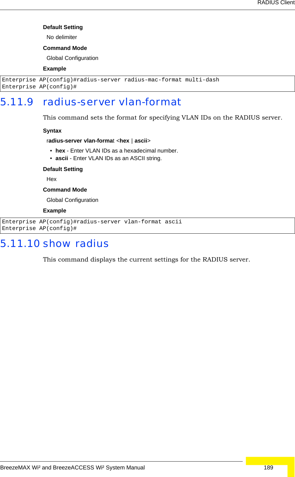
![188 OperationChapter 5 - Command Line InterfaceDefault Setting 0 (disabled)Command Mode Global ConfigurationCommand Usage • When the RADIUS Accounting server UDP port is specified, a RADIUS accounting session is automatically started for each user that is successfully authenticated to the AP.Example 5.11.7 radius-server timeout-interimThis command sets the interval between transmitting accounting updates to the RADIUS server.Syntax radius-server [secondary] timeout-interim <number_of_seconds>•secondary - Secondary server.•number_of_seconds - Number of seconds the waits between transmitting accounting updates. (Range: 60-86400)Default Setting 3600Command Mode Global ConfigurationCommand Usage • The • sends periodic accounting updates after every interim period until the user logs off and a “stop” message is sent.Example 5.11.8 radius-server radius-mac-formatThis command sets the format for specifying MAC addresses on the RADIUS server.Syntaxradius-server radius-mac-format <multi-colon | multi-dash | no-delimiter | single-dash>•multi-colon - Enter MAC addresses in the form xx:xx:xx:xx:xx:xx.•multi-dash - Enter MAC addresses in the form xx-xx-xx-xx-xx-xx.•no-delimiter - Enter MAC addresses in the form xxxxxxxxxxxx.•single-dash - Enter MAC addresses in the form xxxxxx-xxxxxx.Enterprise AP(config)#radius-server port-accounting 1813Enterprise AP(config)#Enterprise AP(config)#radius-server timeout-interim 500Enterprise AP(config)#](https://usermanual.wiki/Accton-Technology/OAP2611A/User-Guide-758212-Page-212.png)
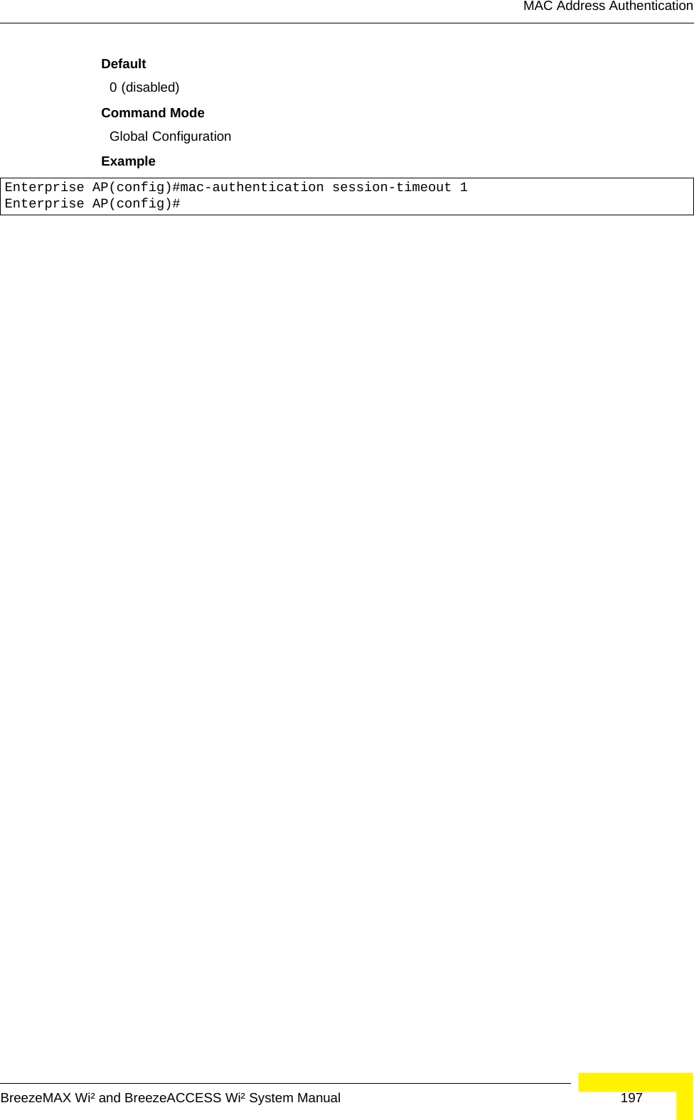
![196 OperationChapter 5 - Command Line InterfaceDefaultNoneCommand ModeGlobal ConfigurationExampleRelated Commands802.1x-supplicant user (page 192)5.13.4 mac-authentication serverThis command sets address filtering to be performed with local or remote options. Use the no form to disable MAC address authentication.Syntaxmac-authentication server [local | remote]•local - Authenticate the MAC address of wireless clients with the local authentication database during 802.11 association.•remote - Authenticate the MAC address of wireless clients with the RADIUS server during 802.1X authentication.DefaultDisabledCommand ModeGlobal ConfigurationExampleRelated Commandsaddress filter entry (page 195)radius-server address (page 185)802.1x-supplicant user (page 192)5.13.5 mac-authentication session-timeoutThis command sets the interval at which associated clients will be re-authenticated with the RADIUS server authentication database. Use the no form to disable reauthentication.Syntaxmac-authentication session-timeout <minutes>minutes - Re-authentication interval. (Range: 0-1440)Enterprise AP(config)#address filter delete 00-70-50-cc-99-1b Enterprise AP(config)#Enterprise AP(config)#mac-authentication server remoteEnterprise AP(config)#](https://usermanual.wiki/Accton-Technology/OAP2611A/User-Guide-758212-Page-220.png)
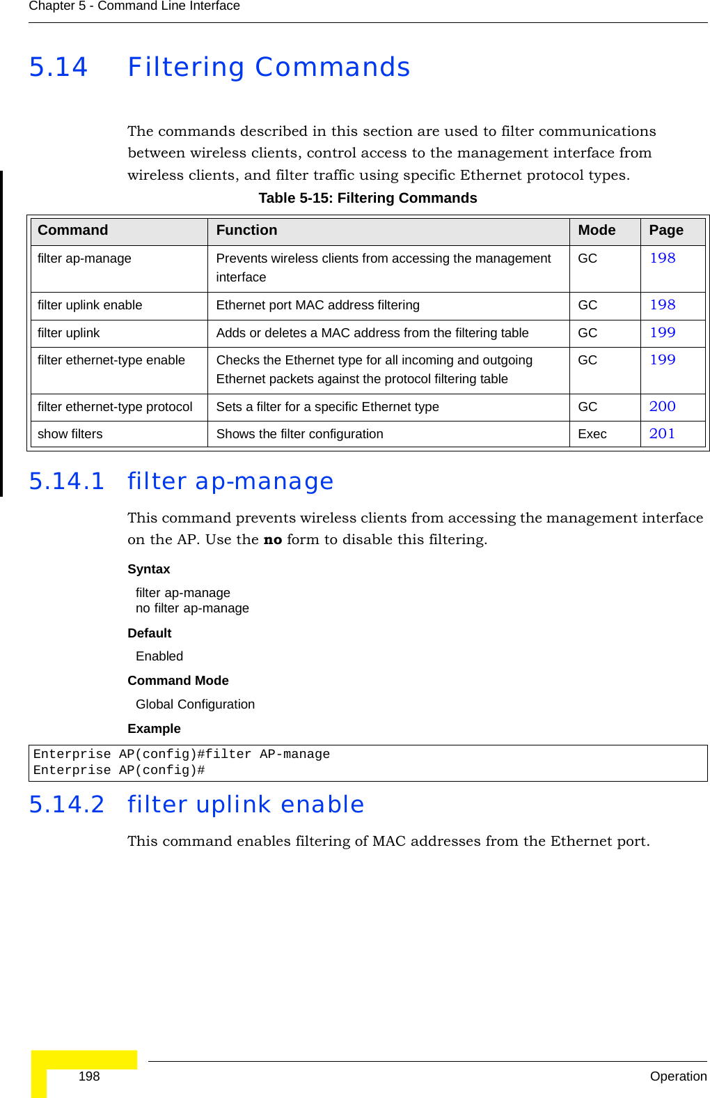
![Filtering CommandsBreezeMAX Wi² and BreezeACCESS Wi² System Manual 199Syntax[no] filter uplink enableDefaultDisabledCommand ModeGlobal ConfigurationExample5.14.3 filter uplinkThis command adds or deletes MAC addresses from the uplink filtering table.Syntaxfilter uplink <add | delete> MAC addressMAC address - Specifies a MAC address in the form xx-xx-xx-xx-xx-xx. A maximum of four addresses can be added to the filtering table.DefaultDisabledCommand ModeGlobal ConfigurationExample5.14.4 filter ethernet-type enableThis command checks the Ethernet type on all incoming and outgoing Ethernet packets against the protocol filtering table. Use the no form to disable this feature.Enterprise AP(config)#filter uplink enableEnterprise AP(config)#Enterprise AP(config)#filter uplink add 00-12-34-56-78-9aEnterprise AP(config)#](https://usermanual.wiki/Accton-Technology/OAP2611A/User-Guide-758212-Page-223.png)
![208 OperationChapter 5 - Command Line InterfaceSyntaxshow interface [ethernet]Default Setting Ethernet interfaceCommand Mode ExecExample Enterprise AP#show interface ethernetEthernet Interface Information========================================IP Address : 192.168.1.1Subnet Mask : 255.255.255.0Default Gateway : 192.168.1.253Primary DNS : 192.168.1.55Secondary DNS : 10.1.0.55Speed-duplex : 100Base-TX Half DuplexAdmin status : UpOperational status : Up========================================Enterprise AP#](https://usermanual.wiki/Accton-Technology/OAP2611A/User-Guide-758212-Page-232.png)
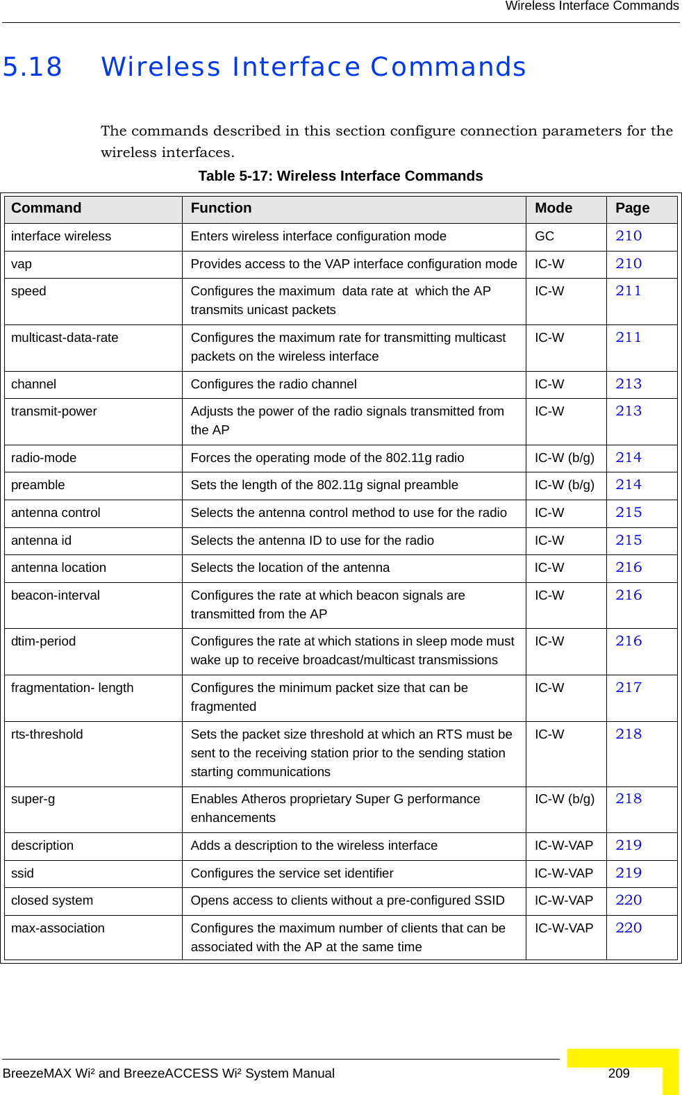
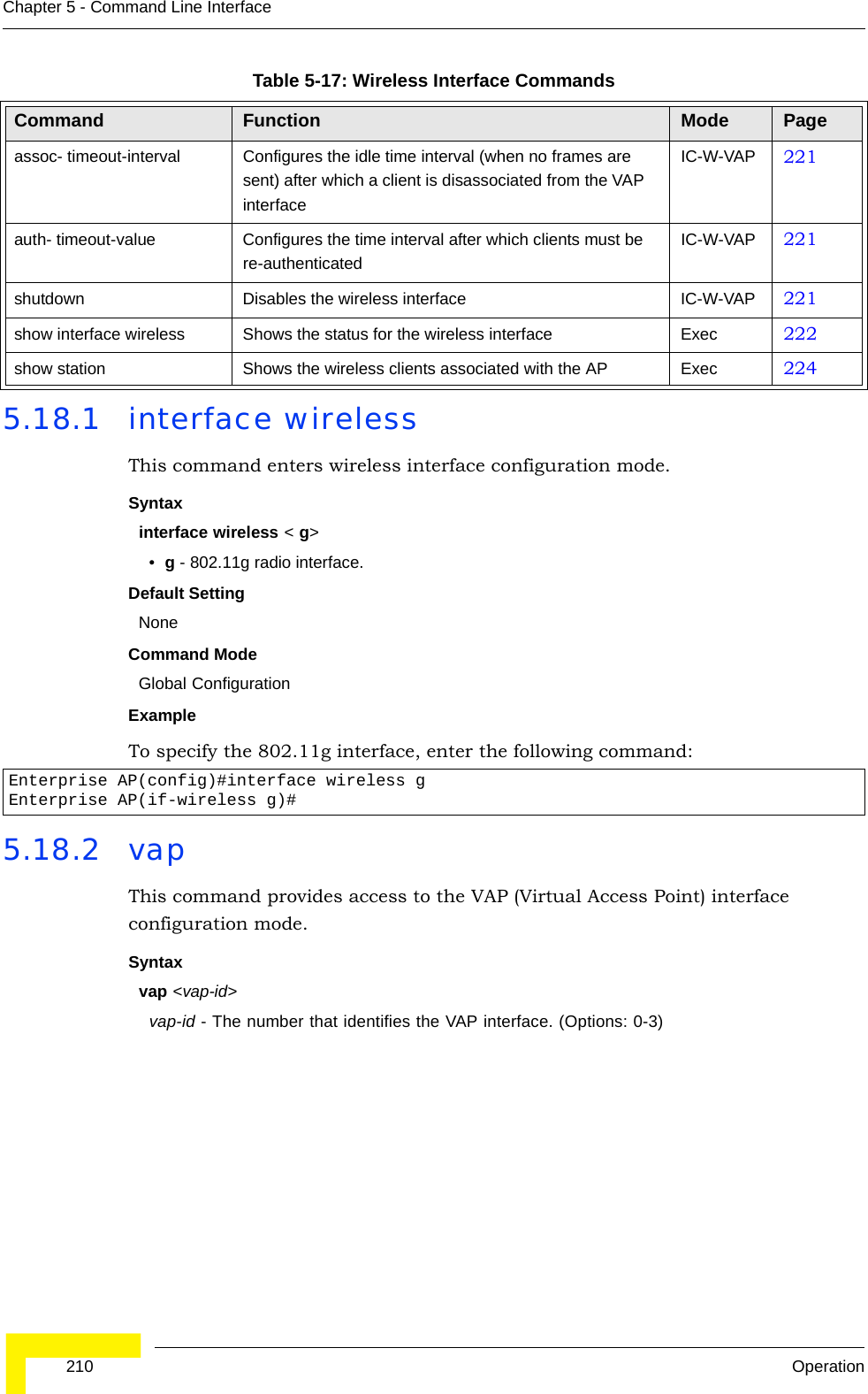
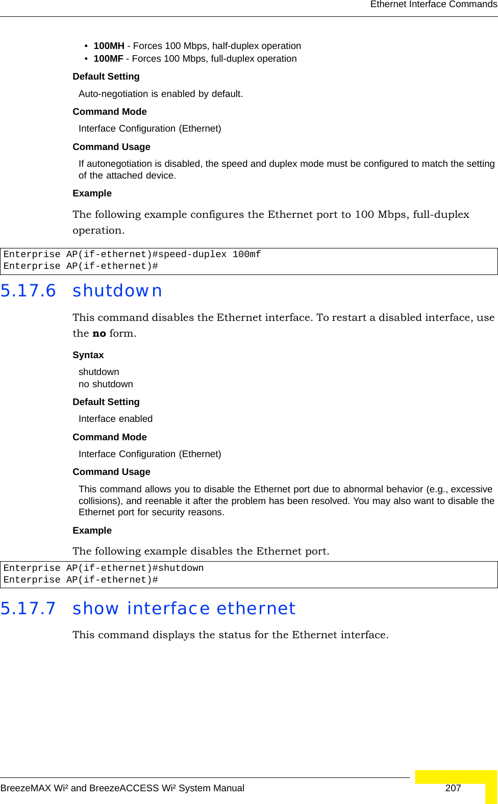
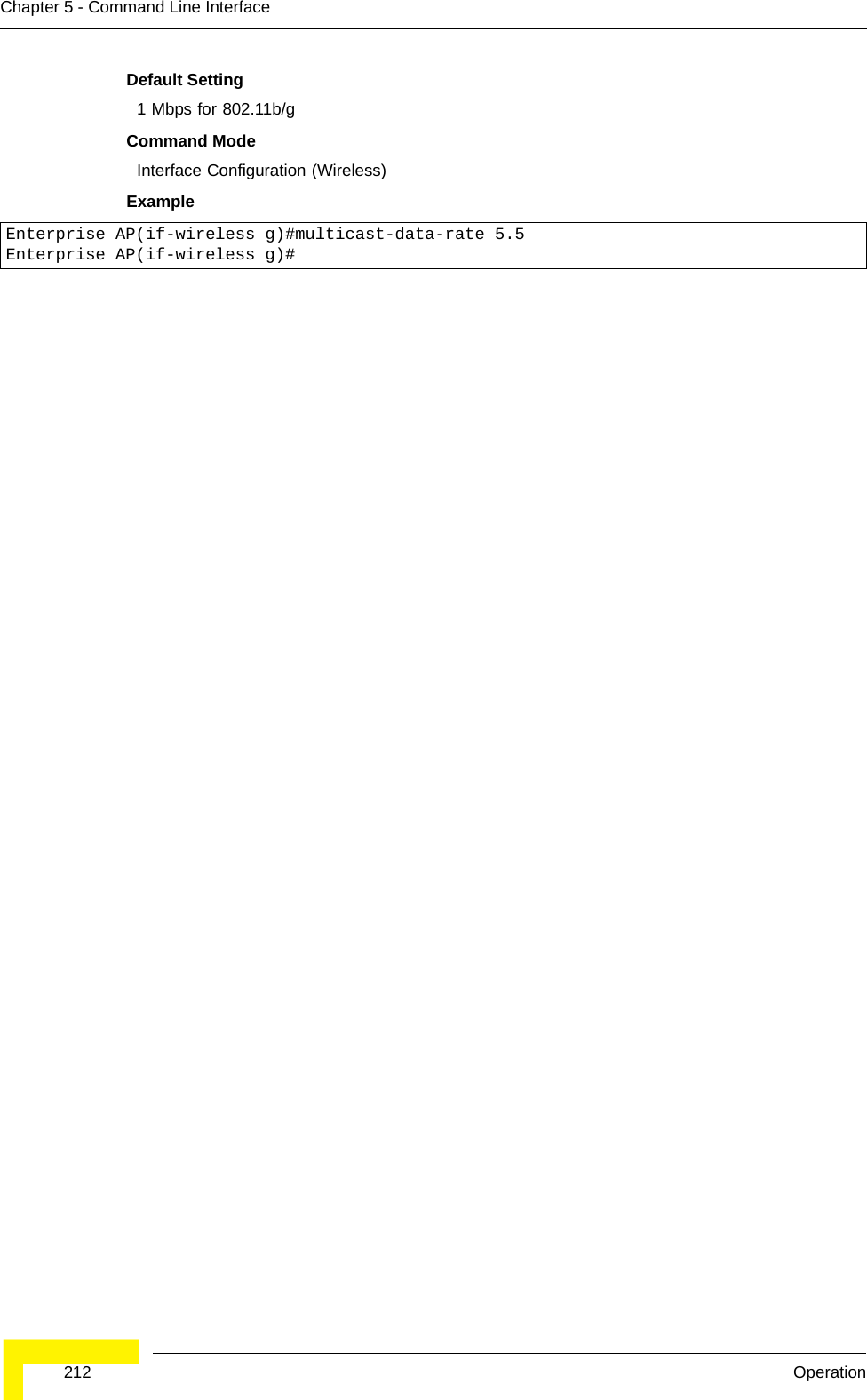
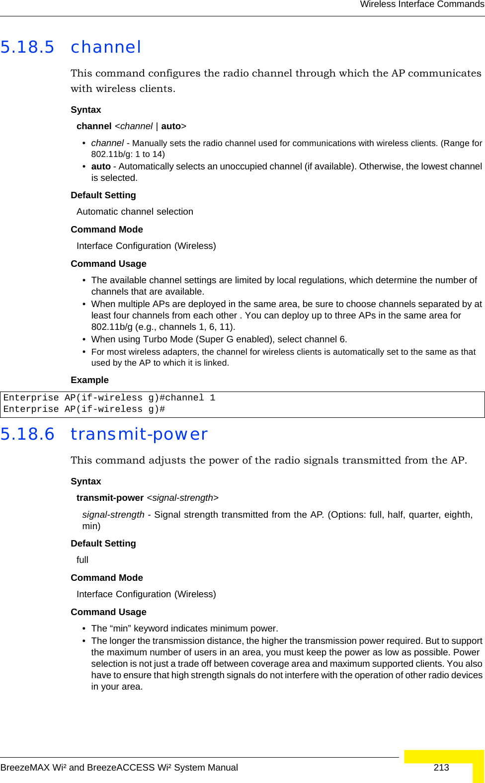
![Wireless Interface CommandsBreezeMAX Wi² and BreezeACCESS Wi² System Manual 211Default Setting NoneCommand Mode Interface Configuration (Wireless)Example5.18.3 speedThis command configures the maximum data rate at which the transmits unicast packets. Syntaxspeed <speed>speed - Maximum access speed allowed for wireless clients. (Options for 802.11b/g: 1, 2, 5.5, 6, 9, 11, 12, 18, 24, 36, 48, 54 Mbps))Default Setting 54 MbpsCommand Mode Interface Configuration (Wireless)Command Usage • The maximum transmission distance is affected by the data rate. The lower the data rate, the longer the transmission distance. Please refer to the table for maximum distances .•When turbo mode is enabled ( page 219), the effective maximum speed specified by this command is double the entered value (e.g., setting the speed to 54 Mbps limits the effective maximum speed to 108 Mbps).Example5.18.4 multicast-data-rateThis command configures the maximum data rate at which the AP transmits multicast and management packets (excluding beacon packets) on the wireless interface. Syntaxmulticast-data-rate <speed>speed - Maximum transmit speed allowed for multicast data.(Options for 802.11b/g; 1, 2, 5.5, 11 MbpsEnterprise AP(if-wireless g)#vap 0Enterprise AP(if-wireless g: VAP[0])#Enterprise AP(if-wireless g)#speed 6Enterprise AP(if-wireless g)#](https://usermanual.wiki/Accton-Technology/OAP2611A/User-Guide-758212-Page-235.png)
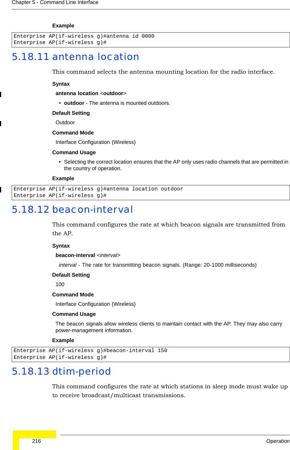
![214 OperationChapter 5 - Command Line InterfaceExample 5.18.7 radio-modeThis command forces the operating mode for the 802.11g wireless interface.Syntaxradio-mode <b | g | b+g>•b - b-only mode: Both 802.11b and 802.11g clients can communicate with the AP, but 802.11g clients can only transfer data at 802.11b standard rates (up to 11 Mbps).•g - g-only mode: Only 802.11g clients can communicate with the AP (up to 54 Mbps).•b+g - b & g mixed mode: Both 802.11b and 802.11g clients can communicate with the AP (up to 54 Mbps).Default Settingb+g modeCommand ModeInterface Configuration (Wireless - 802.11g)Command Usage • For Japan, only 13 channels are available when set to g or b+g modes. When set to b mode, 14 channels are available.• Both the 802.11g and 802.11b standards operate within the 2.4 GHz band. If you are operating in g mode, any 802.11b devices in the service area will contribute to the radio frequency noise and affect network performance.Example5.18.8 preambleThis command sets the length of the signal preamble that is used at the start of a 802.11b/g data transmission.Syntaxpreamble [long | short-or-long]•long - Sets the preamble to long (192 microseconds).•short-or-long - Sets the preamble to short if no 802.11b clients are detected (96 microseconds).Default SettingShort-or-LongCommand ModeInterface Configuration (Wireless - 802.11b/g)Command Usage• Using a short preamble instead of a long preamble can increase data throughput on the AP, but requires that all clients can support a short preamble.• Set the preamble to long to ensure the AP can support all 802.11b and 802.11g clients.Enterprise AP(if-wireless g)#transmit-power halfEnterprise AP(if-wireless g)#Enterprise AP(if-wireless g)#radio-mode gEnterprise AP(if-wireless g)#](https://usermanual.wiki/Accton-Technology/OAP2611A/User-Guide-758212-Page-238.png)
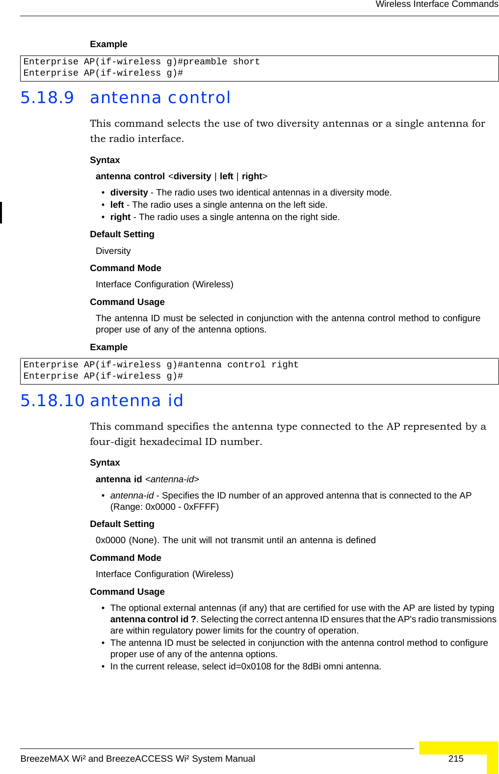
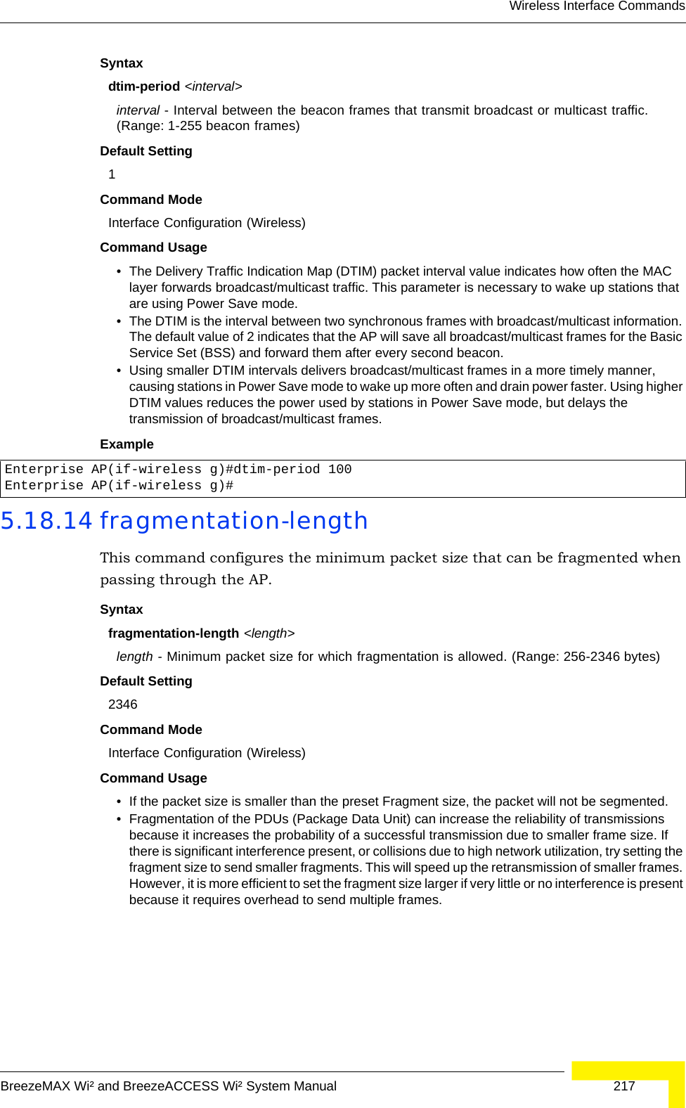
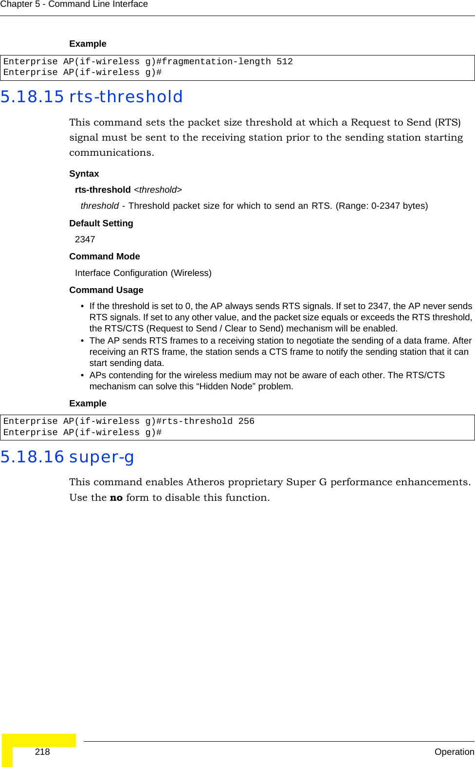
![Wireless Interface CommandsBreezeMAX Wi² and BreezeACCESS Wi² System Manual 219Syntax[no] super-g Default Setting DisabledCommand Mode Interface Configuration (Wireless - 802.11g)Command Usage These enhancements include bursting, compression, fast frames and dynamic turbo. Maximum throughput ranges between 40 to 60 Mbps for connections to Atheros-compatible clients.Example5.18.17 description This command adds a description to a the wireless interface. Use the no form to remove the description.Syntaxdescription <string>no descriptionstring - Comment or a description for this interface. (Range: 1-80 characters)Default Setting Radio G: Enterprise 802.11g Access PointCommand Mode Interface Configuration (Wireless-VAP)Example5.18.18 ssidThis command configures the service set identifier (SSID). Syntaxssid <string>string - The name of a basic service set supported by the AP. (Range: 0 - 7 characters)Enterprise AP(if-wireless g)#super gEnterprise AP(if-wireless g)#Enterprise AP(if-wireless g: VAP[0])#description RD-AP#3Enterprise AP(if-wireless g: VAP[0])#](https://usermanual.wiki/Accton-Technology/OAP2611A/User-Guide-758212-Page-243.png)
![220 OperationChapter 5 - Command Line InterfaceDefault Setting 802.11g Radio: VAP_TEST_11G (0 to 3)Command Mode Interface Configuration (Wireless-VAP)Command Usage Clients that want to connect to the wireless network via an AP must set their SSIDs to the same as that of the AP.Example5.18.19 closed-systemThis command prohibits access to clients without a pre-configured SSID. Use the no form to disable this feature.Syntaxclosed-system no closed-systemDefault Setting DisabledCommand Mode Interface Configuration (Wireless-VAP)Command Usage When closed system is enabled, the AP will not include its SSID in beacon messages. Nor will it respond to probe requests from clients that do not include a fixed SSID.Example5.18.20 max-association This command configures the maximum number of clients that can be associated with the AP at the same time.Syntaxmax-association <count>count - Maximum number of associated stations. (Range: 0-64)Enterprise AP(if-wireless g: VAP[0])#ssid RD-AP#3Enterprise AP(if-wireless g)#Enterprise AP(if-wireless g: VAP[0])#closed-systemEnterprise AP(if-wireless g)#](https://usermanual.wiki/Accton-Technology/OAP2611A/User-Guide-758212-Page-244.png)
![Wireless Interface CommandsBreezeMAX Wi² and BreezeACCESS Wi² System Manual 221Default Setting 64Command Mode Interface Configuration (Wireless-VAP)Example 5.18.21 assoc-timeout-intervalThis command configures the idle time interval (when no frames are sent) after which the client is disassociated from the VAP interface.Syntaxassoc-timeout-interval <minutes>minutes - The number of minutes of inactivity before disassociation. (Range: 5-60)Default Setting 30Command Mode Interface Configuration (Wireless-VAP)Example5.18.22 auth-timeout-valueThis command configures the time interval within which clients must complete authentication to the VAP interface.Syntaxauth-timeout-value <minutes>minutes - The number of minutes before re-authentication. (Range: 5-60)Default Setting 60Command Mode Interface Configuration (Wireless-VAP)Example5.18.23 shutdown This command disables the wireless interface. Use the no form to restart the interface.Enterprise AP(if-wireless g: VAP[0])#max-association 32Enterprise AP(if-wireless g)#Enterprise AP(if-wireless g: VAP[0])#association-timeout-interval 20Enterprise AP(if-wireless g: VAP[0])#Enterprise AP(if-wireless g: VAP[0])#auth-timeout-value 40Enterprise AP(if-wireless g: VAP[0])#](https://usermanual.wiki/Accton-Technology/OAP2611A/User-Guide-758212-Page-245.png)
![222 OperationChapter 5 - Command Line InterfaceSyntax shutdownno shutdownDefault Setting Interface enabledCommand Mode Interface Configuration (Wireless-VAP)Command UsageYou must first enable VAP interface 0 before you can enable VAP interfaces 1, 2, 3, 4, 5, 6, or 7.Example 5.18.24 show interface wirelessThis command displays the status for the wireless interface.Syntaxshow interface wireless < g> vap-id•g - 802.11g radio interface.•vap-id - The number that identifies the VAP interface. (Options: 0~3)Enterprise AP(if-wireless g: VAP[0])#shutdownEnterprise AP(if-wireless g)#](https://usermanual.wiki/Accton-Technology/OAP2611A/User-Guide-758212-Page-246.png)
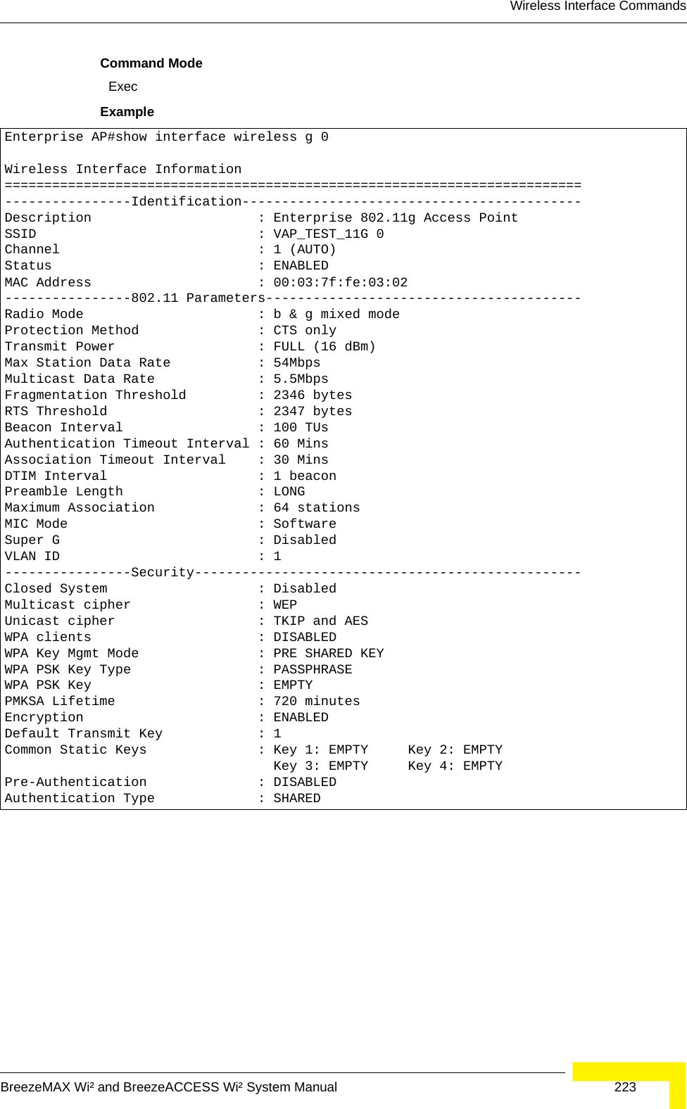
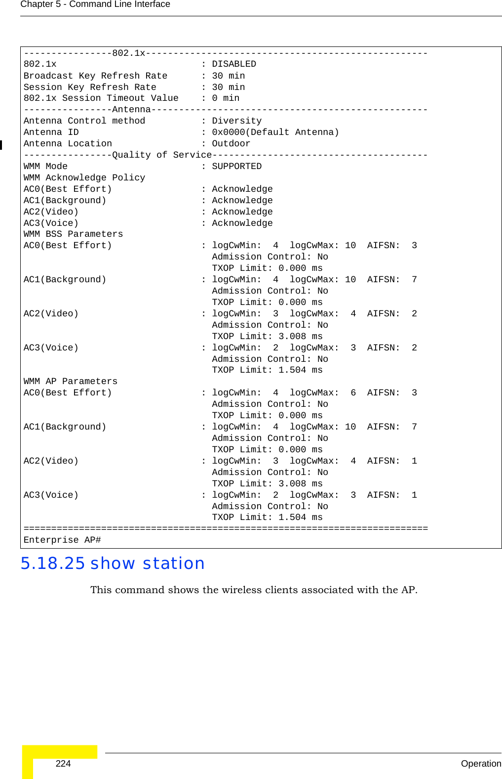
![Wireless Interface CommandsBreezeMAX Wi² and BreezeACCESS Wi² System Manual 225Command Mode ExecExample Enterprise AP#show stationStation Table Information========================================================if-wireless g VAP [0] :802.11g Channel : 60No 802.11g Channel Stations....if-wireless G VAP [0] :802.11g Channel : 1802.11g Channel Station TableStation Address : 00-04-23-94-9A-9C VLAN ID: 0Authenticated Associated Forwarding KeyTypeTRUE FALSE FALSE NONECounters:pkts Tx / Rx bytes Tx / Rx 20/ 0 721/ 0Time:Associated LastAssoc LastDisAssoc LastAuth 0 0 0 0if-wireless G VAP [1] :802.11g Channel : 1No 802.11g Channel Stations....Enterprise AP#](https://usermanual.wiki/Accton-Technology/OAP2611A/User-Guide-758212-Page-249.png)
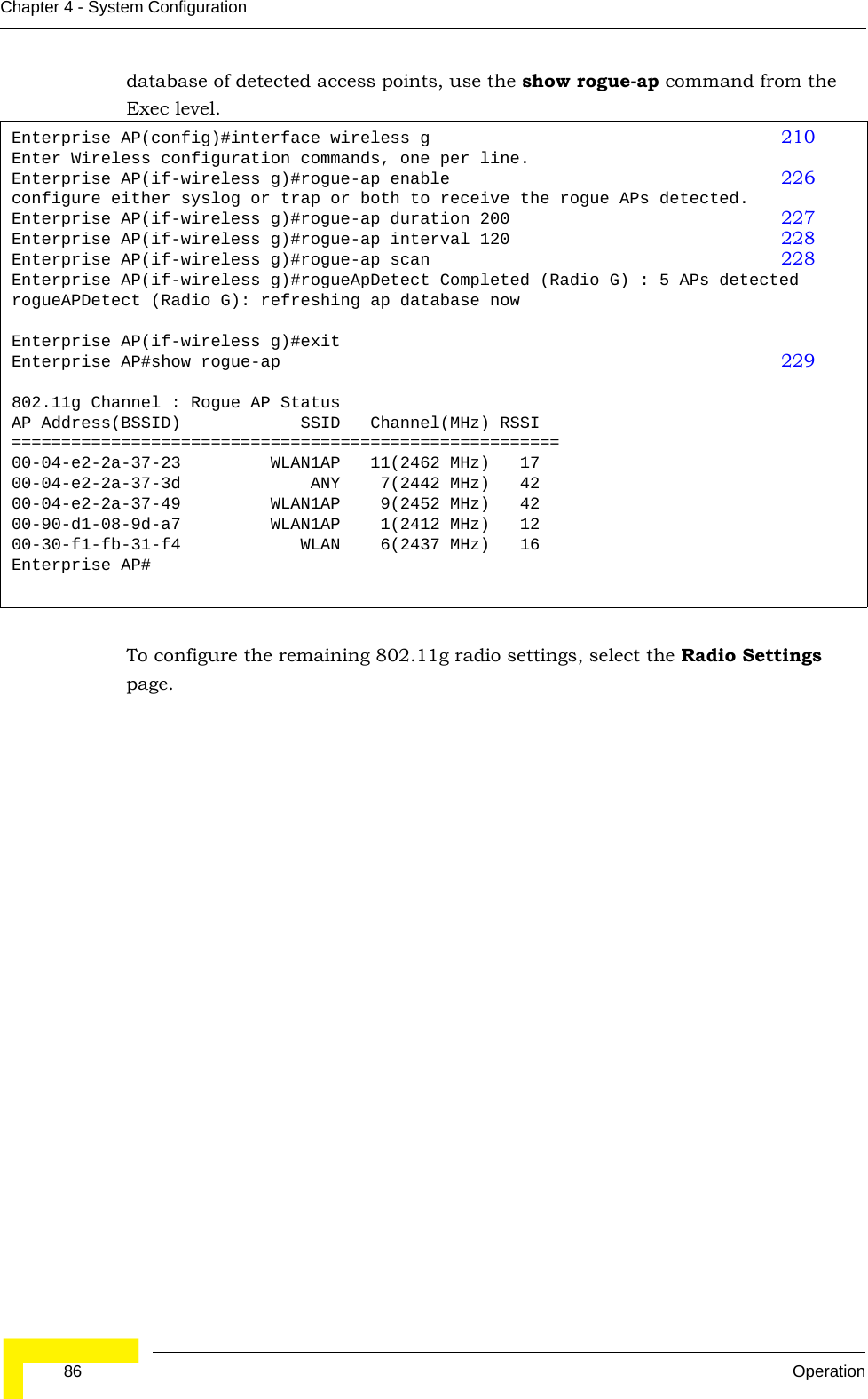
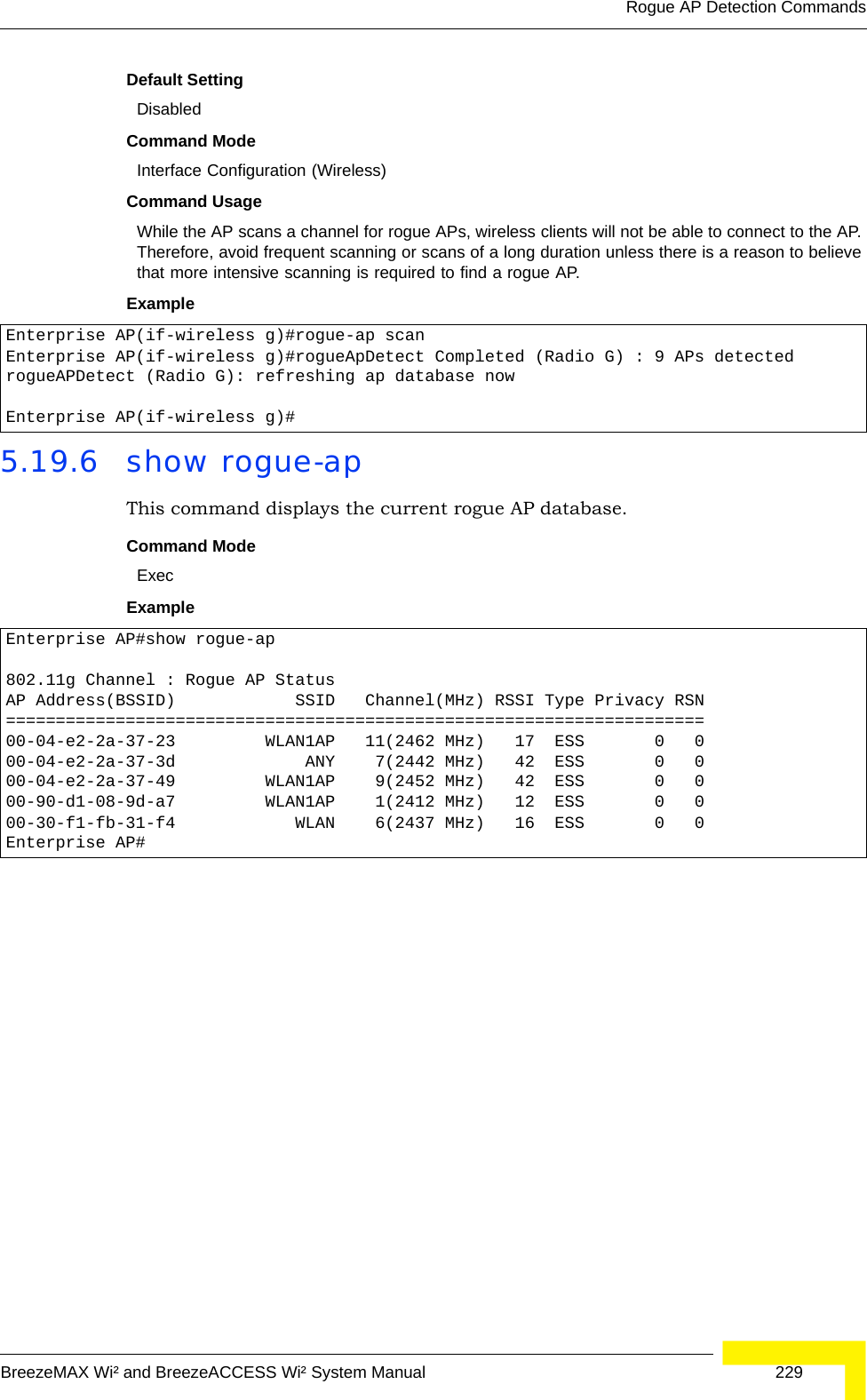
![226 OperationChapter 5 - Command Line Interface5.19 Rogue AP Detection CommandsA “rogue AP” is either an AP that is not authorized to participate in the wireless network, or an AP that does not have the correct security configuration. Rogue APs can potentially allow unauthorized users access to the network. Alternatively, client stations may mistakenly associate to a rogue AP and be prevented from accessing network resources. Rogue APs may also cause radio interference and degrade the wireless LAN performance.The AP can be configured to periodically scan all radio channels and find other APs within range. A database of nearby APs is maintained where any rogue APs can be identified.5.19.1 rogue-ap enableThis command enables the periodic detection of nearby APs. Use the no form to disable periodic detection.Syntax[no] rogue-ap enableDefault SettingDisabledCommand Mode Interface Configuration (Wireless)Command Usage • While the AP scans a channel for rogue APs, wireless clients will not be able to connect to the AP. Therefore, avoid frequent scanning or scans of a long duration unless there is a reason to believe that more intensive scanning is required to find a rogue AP.• A “rogue AP” is either an AP that is not authorized to participate in the wireless network, or an AP that does not have the correct security configuration. Rogue APs can be identified by unknown BSSID (MAC address) or SSID configuration. A database of nearby sh• s should therefore be maintained on a RADIUS server, allowing any rogue APs to be identified (see “rogue-ap authenticate” on page 227). The rogue AP database can be viewed using Table 5-18: Rogue AP Detection CommandsCommand Function Mode Pagerogue-ap enable Enables the periodic detection of other nearby APs GC 226rogue-ap authenticate Enables identification of all APs GC 227rogue-ap duration Sets the duration that all channels are scanned GC 227rogue-ap interval Sets the time between each scan GC 228rogue-ap scan Forces an immediate scan of all radio channels GC 228show rogue-ap Shows the current database of detected APs Exec 229](https://usermanual.wiki/Accton-Technology/OAP2611A/User-Guide-758212-Page-250.png)
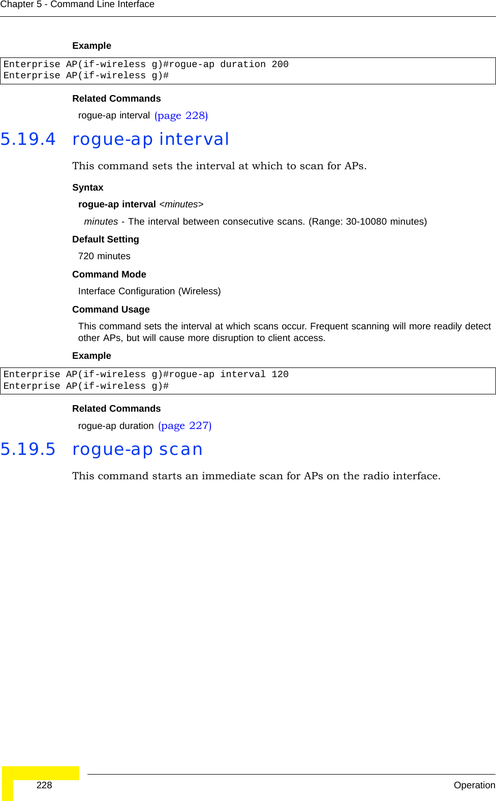
![Rogue AP Detection CommandsBreezeMAX Wi² and BreezeACCESS Wi² System Manual 227the show rogue-ap command.• The AP sends Syslog messages for each detected AP during a rogue AP scan.Example 5.19.2 rogue-ap authenticateThis command forces the unit to authenticate all APs on the network. Use the no form to disable this function.Syntax[no] rogue-ap authenticateDefault SettingDisabledCommand Mode Interface Configuration (Wireless)Command Usage Enabling authentication in conjunction with a database of approved APs stored on a RADIUS server allows the AP to discover rogue APs. With authentication enabled and a configure RADIUS server, the AP checks the MAC address/Basic Service Set Identifier (BSSID) of each AP that it finds against a RADIUS server to determine whether the AP is allowed. With authentication disabled, the AP can identify its neighboring APs only; it cannot identify whether the APs are allowed or are rogues. If you enable authentication, you should also configure a RADIUS server for this AP (see “RADIUS” on page 48).Example 5.19.3 rogue-ap durationThis command sets the scan duration for detecting APs.Syntaxrogue-ap duration <milliseconds>milliseconds - The duration of the scan. (Range: 100-1000 milliseconds)Default Setting350 millisecondsCommand Mode Interface Configuration (Wireless)Command Usage • During a scan, client access may be disrupted and new clients may not be able to associate to the AP. If clients experience severe disruption, reduce the scan duration time.• A long scan duration time will detect more APs in the area, but causes more disruption to client access.Enterprise AP(if-wireless g)#rogue-ap enableconfigure either syslog or trap or both to receive the rogue APs detected.Enterprise AP(if-wireless g)#Enterprise AP(if-wireless g)#rogue-ap authenticateEnterprise AP(if-wireless g)#](https://usermanual.wiki/Accton-Technology/OAP2611A/User-Guide-758212-Page-251.png)
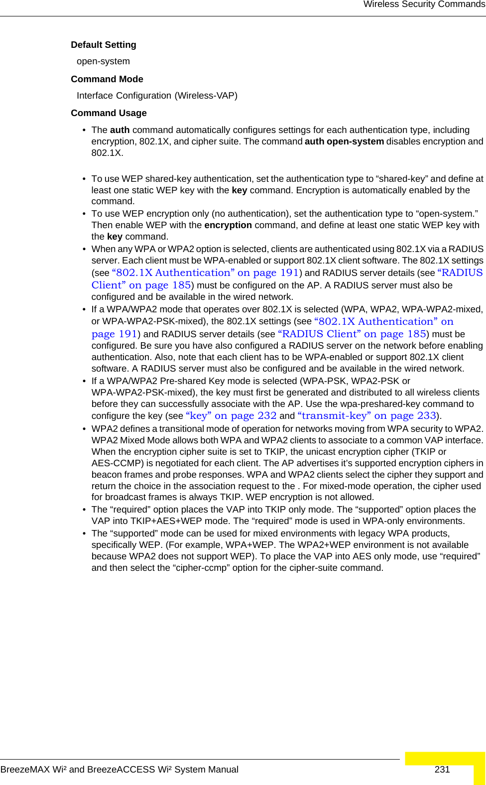
![232 OperationChapter 5 - Command Line InterfaceExampleRelated Commandsencryption (page 232)key (page 232)5.20.2 encryption This command enables data encryption for wireless communications. Use the no form to disable data encryption.Syntaxencryptionno encryptionDefault Setting disabledCommand Mode Interface Configuration (Wireless-VAP)Command Usage • Wired Equivalent Privacy (WEP) is implemented in this device to prevent unauthorized access to your wireless network. For more secure data transmissions, enable encryption with this command, and set at least one static WEP key with the key command. • The WEP settings must be the same on each client in your wireless network.• Note that WEP protects data transmitted between wireless nodes, but does not protect any transmissions over your wired network or over the Internet.• You must enable data encryption in order to enable all types of encryption (WEP, TKIP, and AES-CCMP) in the AP. ExampleRelated Commandskey (page 232)5.20.3 key This command sets the keys used for WEP encryption. Use the no form to delete a configured key.Syntaxkey <index> <size> <type> <value>no key index•index - Key index. (Range: 1-4)•size - Key size. (Options: 64, 128, or 152 bits)•type - Input format. (Options: ASCII, HEX)•value - The key string.- For 64-bit keys, use 5 alphanumeric characters or 10 hexadecimal digits.Enterprise AP(if-wireless g: VAP[0])#auth shared-keyEnterprise AP(if-wireless g)#Enterprise AP(if-wireless g: VAP[0])#encryptionEnterprise AP(if-wireless g)#](https://usermanual.wiki/Accton-Technology/OAP2611A/User-Guide-758212-Page-256.png)
![234 OperationChapter 5 - Command Line InterfaceExample 5.20.5 cipher-suite This command defines the cipher algorithm used to encrypt the global key for broadcast and multicast traffic when using WiFi Protected Access (WPA) security. Syntaxmulticast-cipher <aes-ccmp | tkip | wep>•aes-ccmp - Use AES-CCMP encryption for the unicast and multicast cipher.•tkip - Use TKIP encryption for the multicast cipher. TKIP or AES-CCMP can be used for the unicast cipher depending on the capability of the client. •wep - Use WEP encryption for the multicast cipher. TKIP or AES-CCMP can be used for the unicast cipher depending on the capability of the client. Default Setting wepCommand Mode Interface Configuration (Wireless-VAP)Command Usage • WPA enables the AP to support different unicast encryption keys for each client. However, the global encryption key for multicast and broadcast traffic must be the same for all clients.• If any clients supported by the AP are not WPA enabled, the multicast-cipher algorithm must be set to WEP.• WEP is the first generation security protocol used to encrypt data crossing the wireless medium using a fairly short key. Communicating devices must use the same WEP key to encrypt and decrypt radio signals. WEP has many security flaws, and is not recommended for transmitting highly sensitive data.• TKIP provides data encryption enhancements including per-packet key hashing (i.e., changing the encryption key on each packet), a message integrity check, an extended initialization vector with sequencing rules, and a re-keying mechanism. Select TKIP if there are clients in the network that are not WPA2 compliant.• TKIP defends against attacks on WEP in which the unencrypted initialization vector in encrypted packets is used to calculate the WEP key. TKIP changes the encryption key on each packet, and rotates not just the unicast keys, but the broadcast keys as well. TKIP is a replacement for WEP that removes the predictability that intruders relied on to determine the WEP key. • AES-CCMP (Advanced Encryption Standard Counter-Mode/CBCMAC Protocol): WPA2 is backward compatible with WPA, including the same 802.1X and PSK modes of operation and support for TKIP encryption. The main enhancement is its use of AES Counter-Mode encryption with Cipher Block Chaining Message Authentication Code (CBC-MAC) for message integrity. The AES Counter-Mode/CBCMAC Protocol (AES-CCMP) provides extremely robust data confidentiality using a 128-bit key. The AES-CCMP encryption cipher is specified as a standard requirement for WPA2. However, the computational intensive operations of AES-CCMP requires hardware support on client devices. Therefore to implement WPA2 in the network, wireless clients must be upgraded to WPA2-compliant hardware.Enterprise AP(if-wireless g: VAP[0])#transmit-key 2Enterprise AP(if-wireless g)#](https://usermanual.wiki/Accton-Technology/OAP2611A/User-Guide-758212-Page-258.png)
![Wireless Security CommandsBreezeMAX Wi² and BreezeACCESS Wi² System Manual 235Example 5.20.6 mic_mode This command specifies how to calculate the Message Integrity Check (MIC). Syntaxmic_mode <hardware | software>•hardware - Uses hardware to calculate the MIC.•software - Uses software to calculate the MIC.Default Setting softwareCommand Mode Interface Configuration (Wireless)Command Usage • The Michael Integrity Check (MIC) is part of the Temporal Key Integrity Protocol (TKIP) encryption used in WiFi Protected Access (WPA) security. The MIC calculation is performed in the AP for each transmitted packet and this can impact throughput and performance. The AP supports a choice of hardware or software for MIC calculation. The performance of the AP can be improved by selecting the best method for the specific deployment. • Using the “hardware” option provides best performance when the number of supported clients is less than 27. • Using the “software” option provides the best performance for a large number of clients on one radio interface. Throughput may be reduced when the 802.11g interface supports a high number of clients simultaneously.Example 5.20.7 wpa-pre-shared-key This command defines a WiFi Protected Access (WPA/WPA2) Pre-shared-key.Syntaxwpa-pre-shared-key <hex | passphrase-key> <value>•hex - Specifies hexadecimal digits as the key input format.•passphrase-key - Specifies an ASCII pass-phrase string as the key input format.•value - The key string. For ASCII input, specify a string between 8 and 63 characters. For HEX input, specify exactly 64 digits.Command Mode Interface Configuration (Wireless-VAP)Command Usage • To support WPA or WPA2 for client authentication, use the auth command to specify the authentication type, and use the wpa-preshared-key command to specify one static key.• If WPA or WPA2 is used with pre-shared-key mode, all wireless clients must be configured with the same pre-shared key to communicate with the AP’s VAP interface.Enterprise AP(if-wireless g: VAP[0])#multicast-cipher TKIPEnterprise AP(if-wireless g)#Enterprise AP(if-wireless g)#mic_mode hardwareEnterprise AP(if-wireless g)#](https://usermanual.wiki/Accton-Technology/OAP2611A/User-Guide-758212-Page-259.png)
![236 OperationChapter 5 - Command Line InterfaceExample Related Commandsauth (page 230)5.20.8 pmksa-lifetime This command sets the time for aging out cached WPA2 Pairwise Master Key Security Association (PMKSA) information for fast roaming.Syntaxpmksa-lifetime <minutes>minutes - The time for aging out PMKSA information. (Range: 0 - 14400 minutes)Default Setting 720 minutesCommand Mode Interface Configuration (Wireless-VAP)Command Usage • WPA2 provides fast roaming for authenticated clients by retaining keys and other security information in a cache, so that if a client roams away from an AP and then returns reauthentication is not required. • When a WPA2 client is first authenticated, it receives a Pairwise Master Key (PMK) that is used to generate other keys for unicast data encryption. This key and other client information form a Security Association that the AP names and holds in a cache. The lifetime of this security association can be configured with this command. When the lifetime expires, the client security association and keys are deleted from the cache. If the client returns to the AP, it requires full reauthentication.• The AP can store up to 256 entries in the PMKSA cache. Example 5.20.9 pre-authentication This command enables WPA2 pre-authentication for fast secure roaming.Syntaxpre-authentication <enable | disable>•enable - Enables pre-authentication for the VAP interface. •disable - Disables pre-authentication for the VAP interface.Enterprise AP(if-wireless g: VAP[0])#wpa-pre-shared-key ASCII agoodsecretEnterprise AP(if-wireless g)#Enterprise AP(if-wireless g: VAP[0])#wpa-pre-shared-key ASCII agoodsecretEnterprise AP(if-wireless g: VAP[0])#](https://usermanual.wiki/Accton-Technology/OAP2611A/User-Guide-758212-Page-260.png)
![Wireless Security CommandsBreezeMAX Wi² and BreezeACCESS Wi² System Manual 237Default Setting DisabledCommand Mode Interface Configuration (Wireless-VAP)Command Usage • Each time a client roams to another AP it has to be fully re-authenticated. This authentication process is time consuming and can disrupt applications running over the network. WPA2 includes a mechanism, known as pre-authentication, that allows clients to roam to a new AP and be quickly associated. The first time a client is authenticated to a wireless network it has to be fully authenticated. When the client is about to roam to another AP in the network, the AP sends pre-authentication messages to the new AP that include the client’s security association information. Then when the client sends an association request to the new AP, the client is known to be already authenticated, so it proceeds directly to key exchange and association.• To support pre-authentication, both clients and APs in the network must be WPA2 enabled.• Pre-authentication requires all APs in the network to be on the same IP subnet.Example Enterprise AP(if-wireless g: VAP[0])#wpa-pre-shared-key ASCII agoodsecretEnterprise AP(if-wireless g: VAP[0])#](https://usermanual.wiki/Accton-Technology/OAP2611A/User-Guide-758212-Page-261.png)
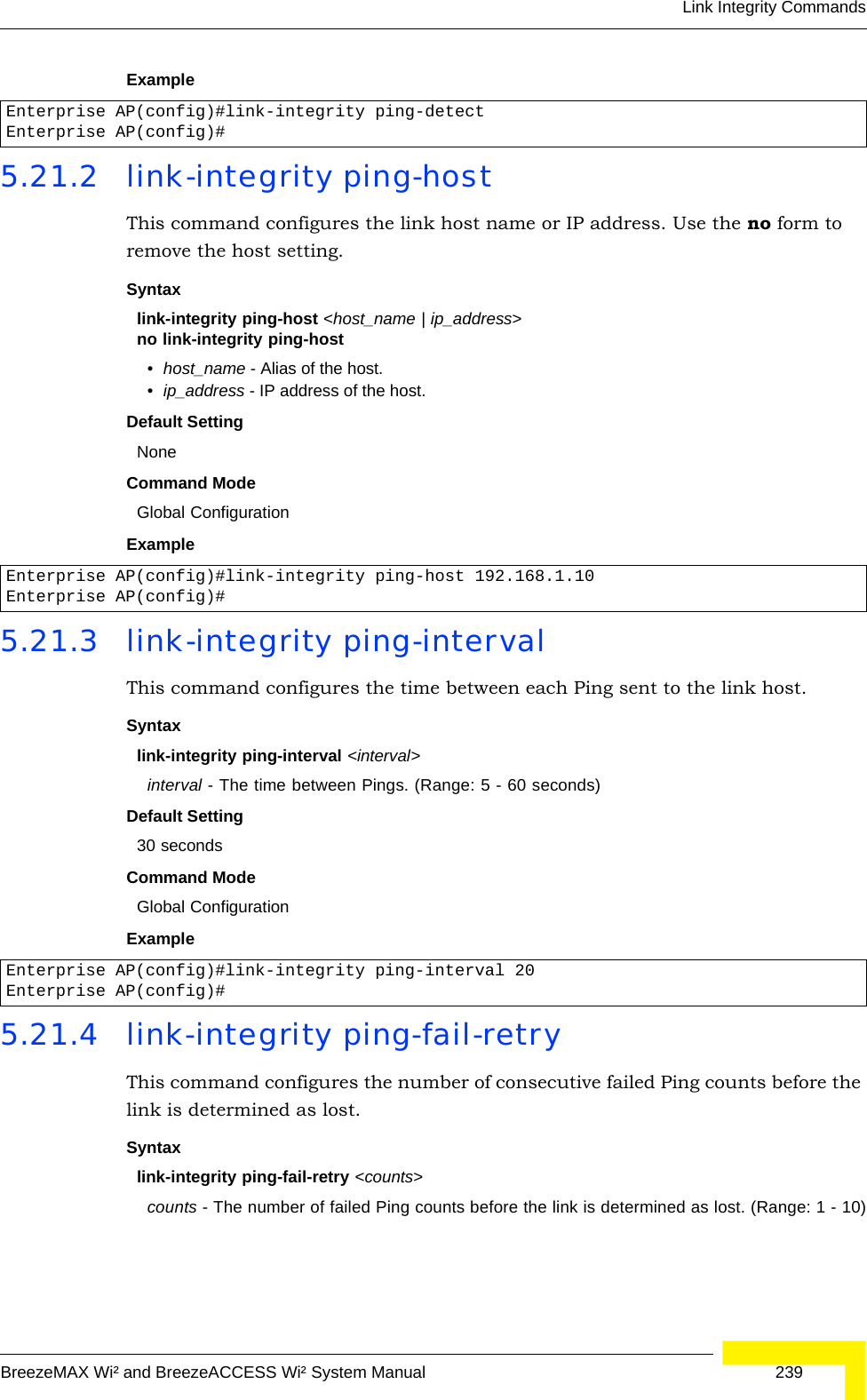
![238 OperationChapter 5 - Command Line Interface5.21 Link Integrity CommandsThe AP provides a link integrity feature that can be used to ensure that wireless clients are connected to resources on the wired network. The AP does this by periodically sending Ping messages to a host device in the wired Ethernet network. If the AP detects that the connection to the host has failed, it disables the radio interfaces, forcing clients to find and associate with another AP. When the connection to the host is restored, the AP re-enables the radio interfaces.5.21.1 link-integrity ping-detectThis command enables link integrity detection. Use the no form to disable link integrity detection.Syntax[no] link-integrity ping-detectDefault SettingDisabledCommand Mode Global ConfigurationCommand Usage • When link integrity is enabled, the IP address of a host device in the wired network must be specified.• The AP periodically sends an ICMP echo request (Ping) packet to the link host IP address. When the number of failed responses (either the host does not respond or is unreachable) exceeds the limit set by the link-integrity ping-fail-retry command, the link is determined as lost.Table 5-20: Link Integrity CommandsCommand Function Mode Pagelink-integrity ping-detect Enables link integrity detection GC 238link-integrity ping-host Specifies the IP address of a host device in the wired networkGC 239link-integrity ping-interval Specifies the time between each Ping sent to the link hostGC 239link-integrity ping-fail-retry Specifies the number of consecutive failed Ping counts before the link is determined as lostGC 239link-integrity ethernet-detect Enables integrity check for Ethernet link GC 240show link-integrity Displays the current link integrity configuration Exec 240](https://usermanual.wiki/Accton-Technology/OAP2611A/User-Guide-758212-Page-262.png)
![240 OperationChapter 5 - Command Line InterfaceDefault Setting6Command Mode Global ConfigurationExample 5.21.5 link-integrity ethernet-detectThis command enables an integrity check to determine whether or not the AP is connected to the wired Ethernet.Syntax[no] link-integrity ethernet-detectDefault SettingDisabledCommand Mode Global ConfigurationExample 5.21.6 show link-integrityThis command displays the current link integrity configuration.Command Mode ExecExample Enterprise AP(config)#link-integrity ping-fail-retry 10Enterprise AP(config)#Enterprise AP(config)#link-integrity ethernet-detectNotification : Ethernet Link Detect SUCCESS - RADIO(S) ENABLEDEnterprise AP(config)#Enterprise AP#show link-integrityLink Integrity Information=========================================================== Ethernet Detect : Enabled Ping Detect : Enabled Target IP/Name : 192.168.0.140 Ping Fail Retry : 6 Ping Interval : 30===========================================================Enterprise AP#](https://usermanual.wiki/Accton-Technology/OAP2611A/User-Guide-758212-Page-264.png)
![IAPP CommandsBreezeMAX Wi² and BreezeACCESS Wi² System Manual 2415.22 IAPP CommandsThe command described in this section enables the protocol signaling required to ensure the successful handover of wireless clients roaming between different 802.11f-compliant APs. In other words, the 802.11f protocol can ensure successful roaming between APs in a multi-vendor environment.5.22.1 iappThis command enables the protocol signaling required to hand over wireless clients roaming between different 802.11f-compliant APs. Use the no form to disable 802.11f signaling.Syntax[no] iappDefaultEnabledCommand ModeGlobal ConfigurationCommand UsageThe current 802.11 standard does not specify the signaling required between APs in order to support clients roaming from one AP to another. In particular, this can create a problem for clients roaming between APs from different vendors. This command is used to enable or disable 802.11f handover signaling between different APs, especially in a multi-vendor environment.ExampleEnterprise AP(config)#iappEnterprise AP(config)#](https://usermanual.wiki/Accton-Technology/OAP2611A/User-Guide-758212-Page-265.png)
![242 OperationChapter 5 - Command Line Interface5.23 VLAN CommandsThe AP can enable the support of VLAN-tagged traffic passing between wireless clients and the wired network. Up to 64 VLAN IDs can be mapped to specific wireless clients, allowing users to remain within the same VLAN as they move around a campus site.When VLAN is enabled on the AP, a VLAN ID (a number between 1 and 4094) can be assigned to each client after successful authentication using IEEE 802.1X and a central RADIUS server. The user VLAN IDs must be configured on the RADIUS server for each user authorized to access the network. If a user does not have a configured VLAN ID, the AP assigns the user to its own configured native VLAN ID.The VLAN commands supported by the AP are listed below. 5.23.1 vlanThis command enables VLANs for all traffic. Use the no form to disable VLANs.Syntax[no] vlan enable DefaultDisabledCommand ModeGlobal ConfigurationCommand Description• When VLANs are enabled, the AP tags frames received from wireless clients with the VLAN ID configured for each client on the RADIUS server. If the VLAN ID has not been configured for a client on the RADIUS server, then the frames are tagged with the AP’s native VLAN ID.CAUTIONWhen VLANs are enabled, the AP’s Ethernet port drops all received traffic that does not include a VLAN tag. To maintain network connectivity to the AP and wireless clients, be sure that the AP is connected to a device port on a wired network that supports IEEE 802.1Q VLAN tags.Table 5-21: VLAN CommandsCommand Function Mode Pagevlan Enables a single VLAN for all traffic GC 242management-vlanid Configures the management VLAN for the AP GC 243vlan-id Configures the default VLAN for the VAP interface IC-W-VAP 243](https://usermanual.wiki/Accton-Technology/OAP2611A/User-Guide-758212-Page-266.png)
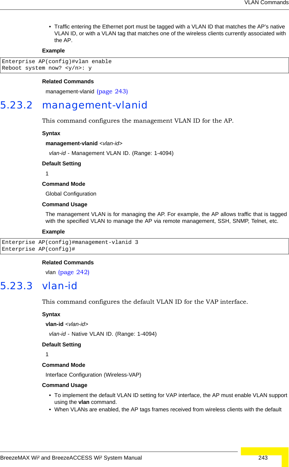
![244 OperationChapter 5 - Command Line InterfaceVLAN ID for the VAP interface. If IEEE 802.1X is being used to authenticate wireless clients, specific VLAN IDs can be configured on the RADIUS server to be assigned to each client. Using IEEE 802.1X and a central RADIUS server, up to 64 VLAN IDs can be mapped to specific wireless clients.• If the VLAN ID has not been configured for a client on the RADIUS server, then the frames are tagged with the default VLAN ID of the VAP interface.ExampleEnterprise AP(if-wireless g: VAP[0])#vlan-id 3Enterprise AP(if-wireless g: VAP[0])#](https://usermanual.wiki/Accton-Technology/OAP2611A/User-Guide-758212-Page-268.png)
![WMM CommandsBreezeMAX Wi² and BreezeACCESS Wi² System Manual 2455.24 WMM CommandsThe AP implements QoS using the WiFi Multimedia (WMM) standard. Using WMM, the AP is able to prioritize traffic and optimize performance when multiple applications compete for wireless network bandwidth at the same time. WMM employs techniques that are a subset of the developing IEEE 802.11e QoS standard and it enables the AP to inter-operate with both WMM- enabled clients and other devices that may lack any WMM functionality.The WMM commands supported by the AP are listed below. 5.24.1 wmmThis command sets the WMM operational mode on the AP. Use the no form to disable WMM.Syntax[no] wmm <supported | required> •supported - WMM will be used for any associated device that supports this feature. Devices that do not support this feature may still associate with the AP. •required - WMM must be supported on any device trying to associated with the AP. Devices that do not support this feature will not be allowed to associate with the AP. DefaultsupportedCommand ModeInterface Configuration (Wireless)Example5.24.2 wmm-acknowledge-policyThis command allows the acknowledgement wait time to be enabled or disabled for each Access Category (AC).Table 5-22: WMM CommandsCommand Function Mode Pagewmm Sets the WMM operational mode on the AP IC-W 245wmm-acknowledge- policyAllows the acknowledgement wait time to be enabled or disabled for each Access Category (AC)IC-W 245wmmparam Configures detailed WMM parameters that apply to the AP (AP) or the wireless clients (BSS)IC-W 246Enterprise AP(if-wireless g)#wmm requiredEnterprise AP(if-wireless g)#](https://usermanual.wiki/Accton-Technology/OAP2611A/User-Guide-758212-Page-269.png)