Accton Technology OAP2611A 802.11b/g Outdoor Access Point User Manual WI2
Accton Technology Corp 802.11b/g Outdoor Access Point WI2
Users Manual

BreezeMAX Wi² and BreezeACCESS
Wi²
System Manual
TE1143
February 2007
P/N
PRELIMINARY

ii BreezeMAX Wi² and BreezeACCESS Wi² System Manual
Document History
Document History
Topic Description Date Issued
This is the document’s first Release December 2006

BreezeMAX Wi² and BreezeACCESS Wi² System Manual iii
Legal Rights
Legal Rights
© Copyright 2006 Alvarion Ltd. All rights reserved.
The material contained herein is proprietary, privileged, and confidential and
owned by Alvarion or its third party licensors. No disclosure thereof shall be made
to third parties without the express written permission of Alvarion Ltd.
Alvarion Ltd. reserves the right to alter the equipment specifications and
descriptions in this publication without prior notice. No part of this publication
shall be deemed to be part of any contract or warranty unless specifically
incorporated by reference into such contract or warranty.
Trade Names
Alvarion®, BreezeCOM®, WALKair®, WALKnet®, BreezeNET®, BreezeACCESS®,
BreezeMANAGE™, BreezeLINK®, BreezeConfig™, BreezeMAX™, AlvariSTAR™,
BreezeLITE™, MGW™, eMGW™, WAVEXpress™, MicroXpress™, WAVEXchange™,
WAVEView™, GSM Network in a Box and TurboWAVE™ and/or other products
and/or services referenced here in are either registered trademarks, trademarks
or service marks of Alvarion Ltd.
All other names are or may be the trademarks of their respective owners.
Statement of Conditions
The information contained in this manual is subject to change without notice.
Alvarion Ltd. shall not be liable for errors contained herein or for incidental or
consequential damages in connection with the furnishing, performance, or use of
this manual or equipment supplied with it.
Warranties and Disclaimers
All Alvarion Ltd. ("Alvarion") products purchased from Alvarion or through any of
Alvarion's authorized resellers are subject to the following warranty and product
liability terms and conditions.
Exclusive Warranty
(a) Alvarion warrants that the Product hardware it supplies and the tangible
media on which any software is installed, under normal use and conditions, will
be free from significant defects in materials and workmanship for a period of
fourteen (14) months from the date of shipment of a given Product to Purchaser
(the "Warranty Period"). Alvarion will, at its sole option and as Purchaser's sole
remedy, repair or replace any defective Product in accordance with Alvarion'
standard R&R procedure.

iv BreezeMAX Wi² and BreezeACCESS Wi² System Manual
Legal Rights
(b) With respect to the Firmware, Alvarion warrants the correct functionality
according to the attached documentation, for a period of fourteen (14) month from
invoice date (the "Warranty Period")". During the Warranty Period, Alvarion may
release to its Customers firmware updates, which include additional performance
improvements and/or bug fixes, upon availability (the "Warranty"). Bug fixes,
temporary patches and/or workarounds may be supplied as Firmware updates.
Additional hardware, if required, to install or use Firmware updates must be
purchased by the Customer. Alvarion will be obligated to support solely the two (2)
most recent Software major releases.
ALVARION SHALL NOT BE LIABLE UNDER THIS WARRANTY IF ITS TESTING
AND EXAMINATION DISCLOSE THAT THE ALLEGED DEFECT IN THE PRODUCT
DOES NOT EXIST OR WAS CAUSED BY PURCHASER'S OR ANY THIRD
PERSON'S MISUSE, NEGLIGENCE, IMPROPER INSTALLATION OR IMPROPER
TESTING, UNAUTHORIZED ATTEMPTS TO REPAIR, OR ANY OTHER CAUSE
BEYOND THE RANGE OF THE INTENDED USE, OR BY ACCIDENT, FIRE,
LIGHTNING OR OTHER HAZARD.
Disclaimer
(a) THE SUPPLIED UNITS SUPPORT 802.11 b/g ONLY.
(b) The Software is sold on an "AS IS" basis. Alvarion, its affiliates or its licensors
MAKE NO WARRANTIES, WHATSOEVER, WHETHER EXPRESS OR IMPLIED,
WITH RESPECT TO THE SOFTWARE AND THE ACCOMPANYING
DOCUMENTATION. ALVARION SPECIFICALLY DISCLAIMS ALL IMPLIED
WARRANTIES OF MERCHANTABILITY AND FITNESS FOR A PARTICULAR
PURPOSE AND NON-INFRINGEMENT WITH RESPECT TO THE SOFTWARE.
UNITS OF PRODUCT (INCLUDING ALL THE SOFTWARE) DELIVERED TO
PURCHASER HEREUNDER ARE NOT FAULT-TOLERANT AND ARE NOT
DESIGNED, MANUFACTURED OR INTENDED FOR USE OR RESALE IN
APPLICATIONS WHERE THE FAILURE, MALFUNCTION OR INACCURACY OF
PRODUCTS CARRIES A RISK OF DEATH OR BODILY INJURY OR SEVERE
PHYSICAL OR ENVIRONMENTAL DAMAGE ("HIGH RISK ACTIVITIES"). HIGH
RISK ACTIVITIES MAY INCLUDE, BUT ARE NOT LIMITED TO, USE AS PART OF
ON-LINE CONTROL SYSTEMS IN HAZARDOUS ENVIRONMENTS REQUIRING
FAIL-SAFE PERFORMANCE, SUCH AS IN THE OPERATION OF NUCLEAR
FACILITIES, AIRCRAFT NAVIGATION OR COMMUNICATION SYSTEMS, AIR
TRAFFIC CONTROL, LIFE SUPPORT MACHINES, WEAPONS SYSTEMS OR
OTHER APPLICATIONS REPRESENTING A SIMILAR DEGREE OF POTENTIAL
HAZARD. ALVARION SPECIFICALLY DISCLAIMS ANY EXPRESS OR IMPLIED
WARRANTY OF FITNESS FOR HIGH RISK ACTIVITIES.

BreezeMAX Wi² and BreezeACCESS Wi² System Manual v
Legal Rights
(c) PURCHASER'S SOLE REMEDY FOR BREACH OF THE EXPRESS
WARRANTIES ABOVE SHALL BE REPLACEMENT OR REFUND OF THE
PURCHASE PRICE AS SPECIFIED ABOVE, AT ALVARION'S OPTION. TO THE
FULLEST EXTENT ALLOWED BY LAW, THE WARRANTIES AND REMEDIES SET
FORTH IN THIS AGREEMENT ARE EXCLUSIVE AND IN LIEU OF ALL OTHER
WARRANTIES OR CONDITIONS, EXPRESS OR IMPLIED, EITHER IN FACT OR BY
OPERATION OF LAW, STATUTORY OR OTHERWISE, INCLUDING BUT NOT
LIMITED TO WARRANTIES, TERMS OR CONDITIONS OF MERCHANTABILITY,
FITNESS FOR A PARTICULAR PURPOSE, SATISFACTORY QUALITY,
CORRESPONDENCE WITH DESCRIPTION, NON-INFRINGEMENT, AND
ACCURACY OF INFORMATION GENERATED. ALL OF WHICH ARE EXPRESSLY
DISCLAIMED. ALVARION' WARRANTIES HEREIN RUN ONLY TO PURCHASER,
AND ARE NOT EXTENDED TO ANY THIRD PARTIES. ALVARION NEITHER
ASSUMES NOR AUTHORIZES ANY OTHER PERSON TO ASSUME FOR IT ANY
OTHER LIABILITY IN CONNECTION WITH THE SALE, INSTALLATION,
MAINTENANCE OR USE OF ITS PRODUCTS.
Limitation of Liability
(a) ALVARION SHALL NOT BE LIABLE TO THE PURCHASER OR TO ANY THIRD
PARTY, FOR ANY LOSS OF PROFITS, LOSS OF USE, INTERRUPTION OF
BUSINESS OR FOR ANY INDIRECT, SPECIAL, INCIDENTAL, PUNITIVE OR
CONSEQUENTIAL DAMAGES OF ANY KIND, WHETHER ARISING UNDER
BREACH OF CONTRACT, TORT (INCLUDING NEGLIGENCE), STRICT LIABILITY
OR OTHERWISE AND WHETHER BASED ON THIS AGREEMENT OR
OTHERWISE, EVEN IF ADVISED OF THE POSSIBILITY OF SUCH DAMAGES.
(b) TO THE EXTENT PERMITTED BY APPLICABLE LAW, IN NO EVENT SHALL
THE LIABILITY FOR DAMAGES HEREUNDER OF ALVARION OR ITS EMPLOYEES
OR AGENTS EXCEED THE PURCHASE PRICE PAID FOR THE PRODUCT BY
PURCHASER, NOR SHALL THE AGGREGATE LIABILITY FOR DAMAGES TO ALL
PARTIES REGARDING ANY PRODUCT EXCEED THE PURCHASE PRICE PAID
FOR THAT PRODUCT BY THAT PARTY (EXCEPT IN THE CASE OF A BREACH OF
A PARTY'S CONFIDENTIALITY OBLIGATIONS).

vi BreezeMAX Wi² and BreezeACCESS Wi² System Manual
Legal Rights
Outdoor Unit and Antenna Installation and Grounding
Ensure that outdoor units, antennas and supporting structures are properly
installed to eliminate any physical hazard to either people or property. Make sure
that the installation of the outdoor unit, antenna and cables is performed in
accordance with all relevant national and local building and safety codes. Even
where grounding is not mandatory according to applicable regulation and national
codes, it is highly recommended to ensure that the outdoor unit and the antenna
mast are grounded and suitable lightning protection devices are used so as to
provide protection against voltage surges and static charges. In any event,
Alvarion is not liable for any injury, damage or regulation violations associated
with or caused by installation, grounding or lightning protection.
Disposal of Electronic and Electrical Waste
Disposal of Electronic and Electrical Waste
Pursuant to the WEEE EU Directive electronic and electrical waste must not be disposed of with
unsorted waste. Please contact your local recycling authority for disposal of this product.

BreezeMAX Wi² and BreezeACCESS Wi² System Manual vii
Legal Rights
Important Notice
This user manual is delivered subject to the following conditions and restrictions:
This manual contains proprietary information belonging to Alvarion Ltd. Such
information is supplied solely for the purpose of assisting properly authorized
users of the respective Alvarion products.
No part of its contents may be used for any other purpose, disclosed to any
person or firm or reproduced by any means, electronic and mechanical,
without the express prior written permission of Alvarion Ltd.
The text and graphics are for the purpose of illustration and reference only.
The specifications on which they are based are subject to change without
notice.
The software described in this document is furnished under a license. The
software may be used or copied only in accordance with the terms of that
license.
Information in this document is subject to change without notice.
Corporate and individual names and data used in examples herein are
fictitious unless otherwise noted.
Alvarion Ltd. reserves the right to alter the equipment specifications and
descriptions in this publication without prior notice. No part of this
publication shall be deemed to be part of any contract or warranty unless
specifically incorporated by reference into such contract or warranty.
The information contained herein is merely descriptive in nature, and does not
constitute an offer for the sale of the product described herein.
Any changes or modifications of equipment, including opening of the
equipment not expressly approved by Alvarion Ltd. will void equipment
warranty and any repair thereafter shall be charged for. It could also void the
user's authority to operate the equipment.
Some of the equipment provided by Alvarion and specified in this manual, is
manufactured and warranted by third parties. All such equipment must be
installed and handled in full compliance with the instructions provided by such
manufacturers as attached to this manual or provided thereafter by Alvarion or

viii BreezeMAX Wi² and BreezeACCESS Wi² System Manual
Legal Rights
the manufacturers. Non-compliance with such instructions may result in serious
damage and/or bodily harm and/or void the user's authority to operate the
equipment and/or revoke the warranty provided by such manufacturer.

BreezeMAX Wi² and BreezeACCESS Wi² System Manual ix
Compliances
Compliances
Federal Communication Commission Interference Statement
This equipment has been tested and found to comply with the limits for a Class B
digital device, pursuant to Part 15 of the FCC Rules. These limits are designed to
provide reasonable protection against harmful interference in a residential
installation. This equipment generates, uses and can radiate radio frequency
energy and, if not installed and used in accordance with the instructions, may
cause harmful interference to radio communications. However, there is no
guarantee that interference will not occur in a particular installation. If this
equipment does cause harmful interference to radio or television reception, which
can be determined by turning the equipment off and on, the user is encouraged to
try to correct the interference by one of the following measures:
Reorient or relocate the receiving antenna
Increase the separation between the equipment and receiver
Connect the equipment into an outlet on a circuit different from that to which
the receiver is connected
Consult the dealer or an experienced radio/TV technician for help
FCC Caution: Any changes or modifications not expressly approved by the party
responsible for compliance could void the user’s authority to operate this
equipment. This device complies with Part 15 of the FCC Rules. Operation is
subject to the following two conditions: (1) This device may not cause harmful
interference, and (2) this device must accept any interference received, including
interference that may cause undesired operation.
IMPORTANT NOTE: FCC Radiation Exposure Statement
This equipment complies with FCC radiation exposure limits set forth for an
uncontrolled environment. This equipment should be installed and operated with
a minimum distance of 20 centimeters (8 inches) between the radiator and your
body. This transmitter must not be co-located or operating in conjunction with
any other antenna or transmitter.
EC Conformance Declaration
Hereby, Alvarion, declares that this device is in compliance with the essential requirements and other
relevant provisions of the R&TTE Directive of the European Union (1999/5/EC).This device will be sold
in the following EEA countries:Austria, Italy, Belgium, Liechtenstein, Denmark, Luxembourg, Finland,
Netherlands, France, Norway, Germany, Portugal, Greece, Spain, Iceland, Sweden, Ireland, United Kingdom,
Cyprus, Czech Republic, Estonia, Hungary, Latvia, Lithuania, Malta, Slovakia, Poland, Slovenia.

x BreezeMAX Wi² and BreezeACCESS Wi² System Manual
Compliances
EC Conformance Declaration
Marking by the above symbol indicates compliance with the Essential
Requirements of the R&TTE Directive of the European Union (1999/5/EC). This
equipment meets the following conformance standards:
EN 60950 (IEC 60950) - Product Safety
EN 300 328 - Technical requirements for 2.4 GHz radio equipment
EN 301 489-1 / EN 301 489-17 - EMC requirements for radio equipment
Countries of Operation & Conditions of Use in the European Community
This device is intended to be operated in all countries of the European
Community. Requirements for outdoor operation, license requirements and
allowed channels of operation apply in some countries as described below:
This device requires that the user or installer properly enter the current
country of operation in the command line interface as described in the user
guide, before operating this device.
This device will automatically limit the allowable channels determined by the
current country of operation. Incorrectly entering the country of operation may
result in illegal operation and may cause harmful interference to other system.
The user is obligated to ensure the device is operating according to the
channel limitations, outdoor restrictions and license requirements for each
European Community country as described in this document.
This device may be operated indoors or outdoors in all countries of the
European Community using the 2.4 GHz band: Channels 1 - 13, except where
noted below.
In Italy the end-user must apply for a license from the national spectrum
authority to operate this device outdoors.
In Belgium outdoor operation is only permitted using the 2.46 - 2.4835
GHz band: Channel 13.
In France outdoor operation is only permitted using the 2.4 - 2.454 GHz
band: Channels 1 - 7.
NOTE
The user must use the configuration utility provided with this product to ensure the channels of
operation are in conformance with the spectrum usage rules for European Community countries as
described below.
For product available in the USA market, only channel 1~11 can be operated.
Selection of other channels is not possible.

BreezeMAX Wi² and BreezeACCESS Wi² System Manual xi
Compliances
Safety Compliance
Power Cord Safety
Please read the following safety information carefully before installing the device:
The unit must be connected to an earthed (grounded) outlet to comply with
international safety standards.
Do not connect the unit to an A.C. outlet (power supply) without an earth
(ground) connection.
The appliance coupler (the connector to the unit and not the wall plug) must
have a configuration for mating with an EN 60320/IEC 320 appliance inlet.
The socket outlet must be near to the unit and easily accessible. You can only
remove power from the unit by disconnecting the power cord from the outlet.
This unit operates under SELV (Safety Extra Low Voltage) conditions
according to IEC 60950. The conditions are only maintained if the equipment
to which it is connected also operates under SELV conditions.
France and Peru only
This unit cannot be powered from IT supplies. If your supplies are of IT type, this
unit must be powered by 230 V (2P+T) via an isolation transformer ratio 1:1, with
the secondary connection point labelled Neutral, connected directly to earth
(ground).
WARNING
Installation and removal of the unit must be carried out by qualified personnel only.
IMPORTANT
Before making connections, make sure you have the correct cord set. Check it (read the label on
the cable) against the following:

xii BreezeMAX Wi² and BreezeACCESS Wi² System Manual
Compliances
Power Cord Set
U.S.A. and Canada The cord set must be UL-approved and CSA certified.
The minimum specifications for the flexible cord are:
- No. 18 AWG - not longer than 2 meters, or 16 AWG.
- Type SV or SJ
- 3-conductor
The cord set must have a rated current capacity of at least 10 A
The attachment plug must be an earth-grounding type with NEMA 5-15P
(15 A, 125 V) or NEMA 6-15P (15 A, 250 V) configuration.
Denmark The supply plug must comply with Section 107-2-D1, Standard DK2-1a or
DK2-5a.
Switzerland The supply plug must comply with SEV/ASE 1011.
U.K. The supply plug must comply with BS1363 (3-pin 13 A) and be fitted with
a 5 A fuse which complies with BS1362.
The mains cord must be <HAR> or <BASEC> marked and be of type
HO3VVF3GO.75 (minimum).
Europe The supply plug must comply with CEE7/7 (“SCHUKO”).
The mains cord must be <HAR> or <BASEC> marked and be of type
HO3VVF3GO.75 (minimum).
IEC-320 receptacle.

BreezeMAX Wi² and BreezeACCESS Wi² System Manual xiii
About This Manual
About This Manual
This manual describes the BreezeMAX Wi2 and BreezeACCESS Wi2 unit and
details how to install, operate and manage the access point.
This manual is intended for technicians responsible for installing, setting and
operating the BreezeMAX Wi2 and BreezeACCESS Wi2, and for system
administrators responsible for managing the system.
This manual contains the following chapters and appendices:
Chapter 1 - Product Description - Describes the Wi2 unit and its
functionality.
Chapter 2 - Installation - Describes how to install the Wi2 and how to
connect to subscriber’s equipment.
Chapter 3 - Initial Configuration - Describes how to initially configure the
access point in order to test basic link operation .
Chapter 4 - System Configuration- Describes advanced configuration of the
the access point.
Chapter 5 - Command Line Interface - Describes the command line interface
commands for configuring the access point.
Appendix A - Troubleshooting

Table of Contents
Chapter 1 - Product Description
1.1 Introduction ................................................................................................................2
1.2 Specifications.............................................................................................................4
1.2.1 Radio .............................................................................................................4
1.2.2 Sensitivity ......................................................................................................5
1.2.3 8 dBi Omni Antenna ......................................................................................5
1.2.4 Configuration and Management ....................................................................6
1.2.5 Mechanical ....................................................................................................7
1.2.6 Electrical........................................................................................................ 7
1.2.7 Connectors and LEDs ...................................................................................7
1.2.8 Environmental ..............................................................................................9
1.2.9 Standards Compliance..................................................................................9
Chapter 2 - Hardware Installation
2.1 Hardware Description..............................................................................................12
2.1.1 Bottom Panel...............................................................................................13
2.1.2 Top Panel....................................................................................................14
2.1.3 LED Indicators.............................................................................................14
2.2 Installation Requirements .......................................................................................16
2.2.1 Packing List.................................................................................................16
2.2.2 Additional/Optional Installation Requirements.............................................16
2.2.3 Guidelines for Positioning Wi² .....................................................................17
2.3 Installation ................................................................................................................19
2.3.1 Attaching the SU-ODU to the Mounting Plate .............................................19

xvi BreezeMAX Wi2 and BreezeACCESS VL Wi2 System Manual
Table of Contents
2.3.2 Attaching the Mounting Plate to the Wi² unit ...............................................21
2.3.3 Connecting the Wi² unit to the SU-ODU......................................................22
2.3.4 Preparing the Power Cable .........................................................................25
2.3.5 Pre-Configuration and Testing ....................................................................27
2.3.6 Mounting the Wi² Unit..................................................................................28
2.3.7 Connecting the Grounding Cables ..............................................................31
2.3.8 Connecting to Power Source.......................................................................31
2.4 Post Installation Configuration of the AP/SU-ODU...............................................32
Chapter 3 - Initial Configuration
3.1 Introduction ..............................................................................................................34
3.2 Initial Setup through the CLI...................................................................................35
3.2.1 Configuration via Telnet ..............................................................................35
3.2.2 Configuration via Console ...........................................................................35
3.2.3 Initial Configuration Steps ...........................................................................36
3.3 Logging In.................................................................................................................38
Chapter 4 - System Configuration
4.1 Introduction ..............................................................................................................42
4.2 Advanced Configuration .........................................................................................43
4.2.1 System Identification ...................................................................................44
4.2.2 TCP / IP Settings.........................................................................................45
4.2.3 RADIUS.......................................................................................................48
4.2.4 SSH Settings ...............................................................................................51
4.2.5 Authentication..............................................................................................53
4.2.6 Filter Control................................................................................................57
4.2.7 VLAN ...........................................................................................................60
4.2.8 WDS Settings..............................................................................................62

BreezeMAX Wi2 and BreezeACCESS VL Wi2 System Manual xvii
Table of Contents
4.2.9 AP Management..........................................................................................62
4.2.10 Administration..............................................................................................64
4.2.11 System Log .................................................................................................70
4.2.12 RSSI............................................................................................................74
4.3 SNMP.........................................................................................................................75
4.4 Radio Interface .........................................................................................................81
4.4.1 Radio Settings G (802.11g).........................................................................81
4.4.2 Security .......................................................................................................98
4.5 Status Information .................................................................................................116
4.5.1 Access Point Status ..................................................................................116
4.5.2 Station Status............................................................................................118
4.5.3 Event Logs ................................................................................................120
Chapter 5 - Command Line Interface
5.1 Using the Command Line Interface......................................................................125
5.1.1 Accessing the CLI .....................................................................................125
5.1.2 Console Connection..................................................................................125
5.1.3 Telnet Connection .....................................................................................125
5.2 Entering Commands..............................................................................................127
5.2.1 Keywords and Arguments .........................................................................127
5.2.2 Minimum Abbreviation...............................................................................127
5.2.3 Command Completion...............................................................................127
5.2.4 Getting Help on Commands ......................................................................127
5.2.5 Partial Keyword Lookup ............................................................................128
5.2.6 Negating the Effect of Commands ............................................................128
5.2.7 Using Command History ...........................................................................129
5.2.8 Understanding Command Modes..............................................................129

xviii BreezeMAX Wi2 and BreezeACCESS VL Wi2 System Manual
Table of Contents
5.2.9 Exec Commands.......................................................................................129
5.2.10 Configuration Commands..........................................................................130
5.2.11 Command Line Processing .......................................................................130
5.3 Command Groups..................................................................................................132
5.4 General Commands ...............................................................................................134
5.4.1 configure.................................................................................................... 135
5.4.2 end ............................................................................................................135
5.4.3 exit.............................................................................................................135
5.4.4 ping............................................................................................................136
5.4.5 reset ..........................................................................................................136
5.4.6 show history ..............................................................................................137
5.4.7 show line ...................................................................................................137
5.5 System Management Commands.........................................................................139
5.5.1 country.......................................................................................................140
5.5.2 prompt .......................................................................................................141
5.5.3 system name .............................................................................................142
5.5.4 username ..................................................................................................142
5.5.5 password ...................................................................................................143
5.5.6 ip ssh-server enable..................................................................................143
5.5.7 ip ssh-server port.......................................................................................144
5.5.8 ip telnet-server enable...............................................................................144
5.5.9 ip http port .................................................................................................144
5.5.10 ip http server.............................................................................................. 145
5.5.11 ip http session-timeout ..............................................................................145
5.5.12 ip https port................................................................................................146
5.5.13 ip https server............................................................................................146

BreezeMAX Wi2 and BreezeACCESS VL Wi2 System Manual xix
Table of Contents
5.5.14 APmgmtIP .................................................................................................147
5.5.15 APmgmtUI.................................................................................................148
5.5.16 show apmanagement................................................................................148
5.5.17 show system..............................................................................................149
5.5.18 show version .............................................................................................150
5.5.19 show config ...............................................................................................151
5.5.20 show hardware ..........................................................................................156
5.6 System Logging Commands.................................................................................157
5.6.1 logging on..................................................................................................157
5.6.2 logging host...............................................................................................157
5.6.3 logging console .........................................................................................158
5.6.4 logging level ..............................................................................................158
5.6.5 logging facility-type....................................................................................159
5.6.6 logging clear..............................................................................................160
5.6.7 show logging .............................................................................................160
5.6.8 show event-log .......................................................................................... 161
5.7 System Clock Commands.....................................................................................162
5.7.1 sntp-server ip.............................................................................................162
5.7.2 sntp-server enable.....................................................................................163
5.7.3 sntp-server date-time ................................................................................163
5.7.4 sntp-server daylight-saving .......................................................................164
5.7.5 sntp-server timezone.................................................................................164
5.7.6 show sntp ..................................................................................................165
5.8 DHCP Relay Commands........................................................................................166
5.8.1 dhcp-relay enable......................................................................................166
5.8.2 dhcp-relay..................................................................................................166

xx BreezeMAX Wi2 and BreezeACCESS VL Wi2 System Manual
Table of Contents
5.8.3 show dhcp-relay ........................................................................................167
5.9 SNMP Commands ..................................................................................................168
5.9.1 snmp-server community ............................................................................168
5.9.2 snmp-server contact..................................................................................169
5.9.3 snmp-server location .................................................................................169
5.9.4 snmp-server enable server........................................................................ 170
5.9.5 snmp-server host ......................................................................................170
5.9.6 snmp-server trap ....................................................................................... 171
5.9.7 snmp-server engine-id...............................................................................172
5.9.8 snmp-server user ......................................................................................173
5.9.9 snmp-server targets ..................................................................................174
5.9.10 snmp-server filter.......................................................................................174
5.9.11 snmp-server filter-assignments .................................................................175
5.9.12 show snmp groups ....................................................................................176
5.9.13 show snmp users ......................................................................................176
5.9.14 show snmp group-assignments.................................................................177
5.9.15 show snmp target ......................................................................................177
5.9.16 show snmp filter ........................................................................................178
5.9.17 show snmp filter-assignments ...................................................................178
5.9.18 show snmp ................................................................................................179
5.10 Flash/File Commands............................................................................................181
5.10.1 bootfile.......................................................................................................181
5.10.2 copy ..........................................................................................................181
5.10.3 delete......................................................................................................... 182
5.10.4 dir ..............................................................................................................183

BreezeMAX Wi2 and BreezeACCESS VL Wi2 System Manual xxi
Table of Contents
5.10.5 show bootfile .............................................................................................184
5.11 RADIUS Client ........................................................................................................185
5.11.1 radius-server address................................................................................185
5.11.2 radius-server port ......................................................................................186
5.11.3 radius-server key.......................................................................................186
5.11.4 radius-server retransmit ............................................................................186
5.11.5 radius-server timeout.................................................................................187
5.11.6 radius-server port-accounting....................................................................187
5.11.7 radius-server timeout-interim.....................................................................188
5.11.8 radius-server radius-mac-format ............................................................... 188
5.11.9 radius-server vlan-format .......................................................................... 189
5.11.10 show radius ...............................................................................................189
5.12 802.1X Authentication............................................................................................191
5.12.1 802.1x........................................................................................................ 191
5.12.2 802.1x-supplicant enable ..........................................................................192
5.12.3 802.1x-supplicant user ..............................................................................192
5.12.4 show authentication...................................................................................193
5.13 MAC Address Authentication ...............................................................................194
5.13.1 address filter default.................................................................................. 194
5.13.2 address filter entry.....................................................................................195
5.13.3 address filter delete ...................................................................................195
5.13.4 mac-authentication server.........................................................................196
5.13.5 mac-authentication session-timeout..........................................................196
5.14 Filtering Commands ..............................................................................................198
5.14.1 filter ap-manage ........................................................................................198
5.14.2 filter uplink enable .....................................................................................198

xxii BreezeMAX Wi2 and BreezeACCESS VL Wi2 System Manual
Table of Contents
5.14.3 filter uplink ................................................................................................. 199
5.14.4 filter ethernet-type enable..........................................................................199
5.14.5 filter ethernet-type protocol........................................................................200
5.14.6 show filters ................................................................................................201
5.15 WDS Bridge Commands........................................................................................202
5.16 Spanning Tree Commands....................................................................................203
5.17 Ethernet Interface Commands..............................................................................204
5.17.1 interface ethernet ......................................................................................204
5.17.2 dns server..................................................................................................204
5.17.3 ip address..................................................................................................205
5.17.4 ip dhcp.......................................................................................................206
5.17.5 speed-duplex.............................................................................................206
5.17.6 shutdown...................................................................................................207
5.17.7 show interface ethernet.............................................................................207
5.18 Wireless Interface Commands..............................................................................209
5.18.1 interface wireless.......................................................................................210
5.18.2 vap.............................................................................................................210
5.18.3 speed.........................................................................................................211
5.18.4 multicast-data-rate.....................................................................................211
5.18.5 channel......................................................................................................213
5.18.6 transmit-power........................................................................................... 213
5.18.7 radio-mode ................................................................................................214
5.18.8 preamble ...................................................................................................214
5.18.9 antenna control..........................................................................................215
5.18.10 antenna id..................................................................................................215
5.18.11 antenna location........................................................................................216

BreezeMAX Wi2 and BreezeACCESS VL Wi2 System Manual xxiii
Table of Contents
5.18.12 beacon-interval..........................................................................................216
5.18.13 dtim-period ................................................................................................ 216
5.18.14 fragmentation-length .................................................................................217
5.18.15 rts-threshold ..............................................................................................218
5.18.16 super-g ......................................................................................................218
5.18.17 description .................................................................................................219
5.18.18 ssid............................................................................................................219
5.18.19 closed-system ...........................................................................................220
5.18.20 max-association ........................................................................................220
5.18.21 assoc-timeout-interval ...............................................................................221
5.18.22 auth-timeout-value.....................................................................................221
5.18.23 shutdown...................................................................................................221
5.18.24 show interface wireless .............................................................................222
5.18.25 show station ..............................................................................................224
5.19 Rogue AP Detection Commands..........................................................................226
5.19.1 rogue-ap enable ........................................................................................226
5.19.2 rogue-ap authenticate ...............................................................................227
5.19.3 rogue-ap duration ......................................................................................227
5.19.4 rogue-ap interval .......................................................................................228
5.19.5 rogue-ap scan ...........................................................................................228
5.19.6 show rogue-ap...........................................................................................229
5.20 Wireless Security Commands...............................................................................230
5.20.1 auth ...........................................................................................................230
5.20.2 encryption..................................................................................................232
5.20.3 key.............................................................................................................232
5.20.4 transmit-key...............................................................................................233

xxiv BreezeMAX Wi2 and BreezeACCESS VL Wi2 System Manual
Table of Contents
5.20.5 cipher-suite................................................................................................ 234
5.20.6 mic_mode..................................................................................................235
5.20.7 wpa-pre-shared-key ..................................................................................235
5.20.8 pmksa-lifetime ...........................................................................................236
5.20.9 pre-authentication......................................................................................236
5.21 Link Integrity Commands ......................................................................................238
5.21.1 link-integrity ping-detect ............................................................................238
5.21.2 link-integrity ping-host ...............................................................................239
5.21.3 link-integrity ping-interval...........................................................................239
5.21.4 link-integrity ping-fail-retry .........................................................................239
5.21.5 link-integrity ethernet-detect ......................................................................240
5.21.6 show link-integrity......................................................................................240
5.22 IAPP Commands ....................................................................................................241
5.22.1 iapp............................................................................................................241
5.23 VLAN Commands...................................................................................................242
5.23.1 vlan............................................................................................................242
5.23.2 management-vlanid...................................................................................243
5.23.3 vlan-id........................................................................................................243
5.24 WMM Commands ...................................................................................................245
5.24.1 wmm..........................................................................................................245
5.24.2 wmm-acknowledge-policy .........................................................................245
5.24.3 wmmparam................................................................................................246
Appendix A - Troubleshooting
Glossary................................................................................................253
Index.....................................................................................................259


2System Description
Chapter 1 - Product Description
1.1 Introduction
Alvarion's Wi² suite of converged solutions, including BreezeMAX Wi²and
BreezeACCESS Wi²("Wi²"), unites the advantages of the popular WiFi access with
the powerful capabilities of BreezeMAX or BreezeACCESS VL/4900
(“BreezeACCESS”) systems to provide cost-effective solutions for personal
broadband services.
The Wi² system comprises a self-contained combination of an advanced WiFi
access point and a BreezeMAX or BreezeACCESSSU-ODU that provides backhaul
connectivity. With its advanced roaming software, the Wi² can be deployed almost
anywhere to provide broadband mobility to standard WiFi (IEEE 802.11 b/g) end
user devices. Used in conjunction with Alvarion's market-leading BreezeMAX or
BreezeACCESS base stations, the Wi² can be used to expand the existing
capabilities of Alvarion's WiMAX and pre-WiMAX networks. Using the Wi², a
BreezeMAX or BreezeACCESS network can be used to provide personal
broadband services to high-end business as well as residential users equipped
with WiFi enabled devices such as laptops, PDAs, smart-phones, and portable
gaming devices. As a converged system, the Wi² also gives operators the ability to
seamlessly transition to a fully mobile WiMAX network with managed services for
personal broadband users.
Operating in both licensed and licensed-exempt frequencies, the Wi² system
leverages the easy availability of WiFi technology - along with the power and
robustness of BreezeMAX or BreezeACCESS broadband wireless access system -
to answer critical public and private sector needs such as traffic management,
video surveillance, public Internet access, homeland security, and various
nomadic applications.
The Wi² is a self-contained, robust all-outdoor system that comprises three
elements:
A feature-rich WiFi (IEEE 802.11 b/g) Access Point (AP)
A BreezeMAX/BreezeACCESS VL/BreezeACCESS 4900 SU-ODU (supplied
separately).
A power supply module that provides power to both the WiFi AP and the
SU-ODU.
The Wi² system requires only a single connection to either AC or DC power. With
its easy installation and operation, high performance, and rich security and QoS

Introduction
BreezeMAX Wi² and BreezeACCESS Wi² System Manual 3
feature sets, the Wi² is an ideal solution for operators, municipalities and
communities looking to build metropolitan broadband networks or to integrate
WiFi hot zone capabilities into their existing broadband wireless access networks.
The result is personal broadband services ranging from public Internet access to
public safety and Intranet applications.
NOTE
This document describes how to install and manage the Wi² system, including the installation and
connections of a BreezeMAX or BreezeACCESS SU-ODU when installed on the mounting plate of
the Wi2 system. For details on other installation options for the SU-ODU and how to manage it, refer
to the relevant BreezeMAX or BreezeACCESS VL/4900 documents.

4System Description
Chapter 1 - Product Description
1.2 Specifications
1.2.1 Radio
Table 1-1: Radio Specifications
Item Description
Radio Type IEEE 802.11b/g
Radio Mode 802.11b+g, 802.11b only, 802.11g only
Frequency Band 2400-2497 MHz
Operating Channels ETSI (EUR): 2412 ~ 2472 MHz(CH1-CH13)
MKK (Japan) 11b: 2412 ~ 2484 MHz (CH1-CH14)
MKK (Japan) 11g: 2412 ~ 2472 MHz(CH1-CH13)
France: 2457 ~ 2472 MHz(CH10-CH13)
US & Canada: 2400 ~ 2483.5 MHz(CH1~CH11)
Channel Bandwidth 20 MHz
Data Rates 802.11b: 1, 2, 5.5, 11 Mbps
802.11g: 6, 9, 12, 18, 24, 36, 48, 54 Mbps
Turbo Mode (802.11g Super G) Turbo Mode: 12, 18, 24, 36, 48, 54, 96, 108 Mbps per channel
802.11b Radio Technology Direct Sequence-Spread Spectrum (DSSS)
802.11b Modulation Technique Differential Binary Phase Shift Keying (DBPSK) @ 1 Mbps
Differential Quadrature Phase Shift Keying (DQPSK) @ 2 Mbps
Complementary Code Keying (CCK) @ 5.5 and 11 Mbps
802.11b Radio Technology Orthogonal Frequency Divisional Multiplexing (OFDM)
802.11b Modulation Technique Binary Phase Shift Keying (BPSK) @ 6 and 9 Mbps
Quadrature Phase Shift Keying (QPSK) @ 12 and 18 Mbps
16-Quadrature Amplitude Modulation (QAM) @ 24 & 36 Mbps
64-QAM @ 48 & 54 Mbps
FEC Coding Rates 1/2 2/3, 3/4
Max Tx Power 11b: 20.36dBm
11g: 24.96dBm
11g turbo: 24.53dBm
TPC (Transmit Power Control) 100%, 50%, 25%, 12.5%, Min.
Antenna Ports 2 x N-Type, 50 ohm
Antenna Diversity Rx antenna switching by energy sensing

Specifications
BreezeMAX Wi² and BreezeACCESS Wi² System Manual 5
1.2.2 Sensitivity
1.2.3 8 dBi Omni Antenna
Table 1-2: Sensitivity
Data Rate Sensitivity (dBm)
802.11b, 1 Mbps -96
802.11b, 2 Mbps -93
802.11b, 5.5 Mbps -93
802.11b, 11 Mbps -90
802.11g, 6 Mbps -91
802.11g, 9 Mbps -90
802.11g, 12 Mbps -89
802.11g, 18 Mbps -88
802.11g, 24 Mbps -84
802.11g, 36 Mbps -80
802.11g, 48 Mbps -75
802.11g, 54 Mbps -73
Table 1-3: 8 dBi Omni Antenna
Item Description
Antenna gain 8 dBi
VSWR 2:1 max
Antenna Polarization Linear Vertical
Horizontal Plane 360°
Vertical Plane 15°
Dimensions 52 cm x 1.9 cm diameter
Weight 340 g

6System Description
Chapter 1 - Product Description
1.2.4 Configuration and Management
Table 1-4: Configuration and Management
Item Description
Management options Web-based (HTTP/HTTPS)
Telnet
SSH
SNMP
SNMP agent V1 / V2c, supports 802.11 MIB, RFC-1213 MIB II and private MIB.
Management access Local via Console port
From the backhaul network
From WiFi clients
Management access protection Access Password
Enable/Disable access from wireless clients
Enable/Disable access using web/Telnet/SNMP
Restrict access to authorized stations (by IP)
WiFi Clients Authentication Local/RADIUS MAC List
IEEE 802.1x
Encryption WEP
WPA/TKIP over 802.1x or PSK (Pre-shared Key)
802.11i / WPA2 (AES-CCMP) over 802.1x or PSK
Mixed WPA and WEP clients support
Allocation of IP parameters Configurable or automatic (DHCP client)
WiFi Multi-Media Support Four QoS levels using the WMM standard according to IEEE 802.11e
Software upgrade HTTP/FTP/TFTP
Configuration Upload/Download FTP/TFTP

Specifications
BreezeMAX Wi² and BreezeACCESS Wi² System Manual 7
1.2.5 Mechanical
1.2.6 Electrical
1.2.7 Connectors and LEDs
Table 1-5: Mechanical Specifications
Item Description
Dimensions 278mm (W) X 279mm (H) X 240mm (D)
Weight 5.8Kg (excluding antennas and backhauling CPE)
AC Power Supply 85-260VAC, 47-63Hz, maximum power consumption 2.5A
Mounting Plate Tilt +/- 150
Mounting Plate Rotation +/- 450
Table 1-6: Electrical Specifications
Type Details
AC Power Supply 85-260VAC, 47-63Hz, maximum power consumption 2.5A
DC Power supply 42 VDC to 60 VDC, maximum power consumption 3.5A
AC/DC Power Switching When both AC and DC power sources are connected, AC power input will be
used as long as internal power supplies are working properly. The unit will switch
to DC power source if AC power input fails, or the internal power supplies fail,
and the DC power input is in the proper range.
Table 1-7: Connectors and LEDs
Type Description
AC IN Connection to AC mains. 3-pin power plug, Bulgin PX0732/S/07
SU Ethernet and power connection to backhauling CPE.
RJ-45, in a weather protected service box
AP Ethernet and power connection to AP (PoE).
RJ-45, in a weather protected service box
DC IN Connection to DC power source. 2-pin power plug, Bulgin
PoE Ethernet and power connection, 8-pins DIN jack
10/100Base-T, half/full duplex with auto-negotiation
Console RS232 DTE, 3-pins DIN jack

8System Description
Chapter 1 - Product Description
LEDs Power
Link (Ethernet link integrity/activity)
11b/g: 3 LEDs indicating wireless link activity
Table 1-7: Connectors and LEDs
Type Description

Specifications
BreezeMAX Wi² and BreezeACCESS Wi² System Manual 9
1.2.8 Environmental
1.2.9 Standards Compliance
Table 1-8: Environmental Specifications
Item Details
Operating Temperature -400C to 600C non condensing 5º~55ºC
Storage Temperature -550C to 800C non condensing 5º~70ºC
Humidity Maximum 95%.
Water Proof IP-67
Solar Radiation protection IEC 60068-2-5
Salt IEC 60068 part 2-52
Transportation ETS 300 019-2-2 Class 2.3 Pubic Transportation
Storage shock IEC 68-2-29
Storage drop IEC 68-2-32
Wind operation 160 Km/hour
Wind survival 220 Km/hour
Table 1-9: Standards Compliance
Type Standard
EMC EN55022 CE Class B
FCC Class B Part 15
VCCI Class B
Safety UL / CUL (CSA60950-1, UL60950-1)
CE / CB (EN60950/IEC 60950-1)
Lightning The unit withstand at +4KV of Input surge, 1.2usec rise/fall time, 50µsec duration,
every 10 seconds, for all interfaces.
Radio ETSI 300 328 (11b/g)
ETSI 301 489 (DC power)
FCC Part 15C 15.247/15.207 (11b/g)
TELEC

2
Chapter 2 - Hardware Installation
In This Chapter:
“Hardware Description” on page 12
“Installation Requirements” on page 16
“Installation” on page 19
“Attaching the SU-ODU to the Mounting Plate” on page 19
“Attaching the Mounting Plate to the Wi² unit” on page 21
“Connecting the Wi² unit to the SU-ODU” on page 22
“Preparing the Power Cable” on page 25
“Pre-Configuration and Testing” on page 27
“Mounting the Wi² Unit” on page 28
“Connecting the Antenna(s)” on page 31
“Connecting the Grounding Cables” on page 31
“Connecting to Power Source” on page 31
12 Installation
Chapter 2 - Hardware Installation
2.1 Hardware Description
The Wi² consists of a WiFi access point with an integrated power supply and
interface module that connects to either a BreezeMAX or BreezeACCESS outdoor
unit (SU-ODU) for backhaul and network management software. Each unit is
housed in a weatherproof enclosure for mounting outdoors.
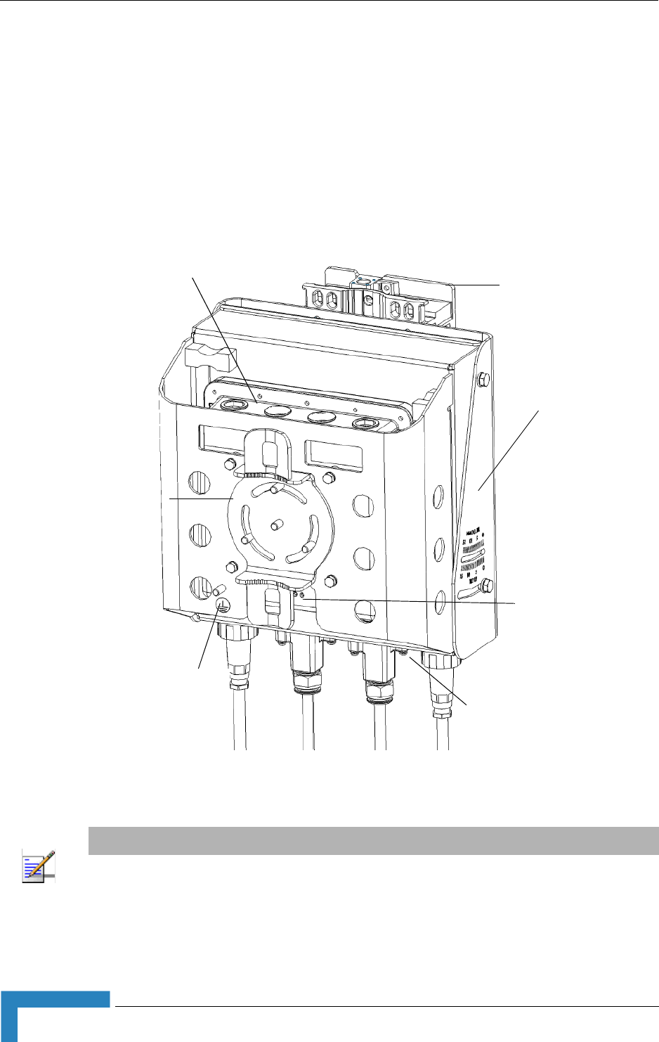
Figure 2-1: Wi² Unit (with SU-ODU attached)
NOTE
The diagram in Figure 2-1 includes a mounting plate and an SU-ODU. The SU-ODU can also be
installed separately, in which case there is no need to attach the mounting plate to the Wi² unit.
s
Pole Mounting
Bracket
Antenna Connectors
(Top Panel)
SU-ODU
Mounting
Plate
Connections
(Bottom Panel)
LEDs
Grounding
Stud
Hardware Description
BreezeMAX Wi² and BreezeACCESS Wi² System Manual 13
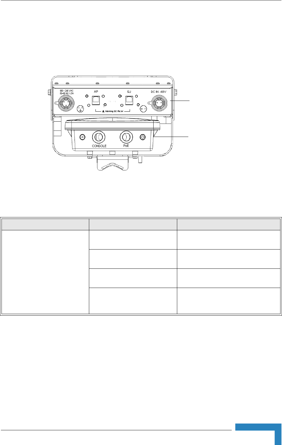
2.1.1 Bottom Panel
Figure 2-2 shows the bottom panel of the Wi² unit and Table 2-10 lists the
components.
Figure 2-2: Bottom Panel (without the SU-ODU)
Table 2-10: Bottom Panel Components
Element Item Description
Power Supply and Interface
Module
Console Port Cover Holder Holder for waterproof protection cover
for console port when port is not in use.
Console Port Connection to console port for system
management.
PoE Port An Ethernet cable connects the PoE port
to the AP port in the WiFi access point.
Impermeability Test Screw Do not remove or loosen this screw.
Doing so may impair the sealing of the
unit against moisture and humidity.
WiFi Access Point
(AP)
Power Supply
and
Interface Module
14 Installation
Chapter 2 - Hardware Installation
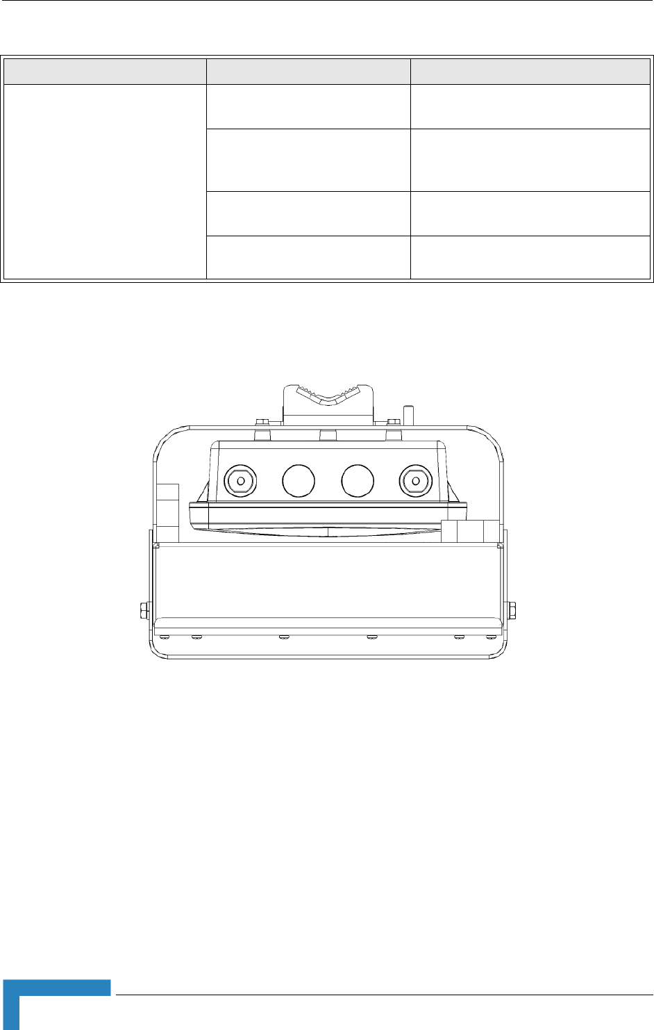
2.1.2 Top Panel
Figure 2-3 shows the top panel of the Wi² unit with two N-type RF connectors for
external antennas.
2.1.3 LED Indicators
The Wi² includes eight status LED indicators. Figure 2-4 shows the LEDs and
Table 2-11 describes the system status.
WiFI Access Point (AP) AC Power Plug 3-pin power plug for connection to AC
power source.
AP Port An Ethernet cable connects the AP port
to the PoE port i n the power supply and
interface module.
SU Port Connection to BreezeMAX or
BreezeACCESS outdoor unit
DC Power Plug) 2-pin power plug for connection to DC
power source.
Figure 2-3: Top Panel (without the SU-ODU)
Table 2-10: Bottom Panel Components
Element Item Description

Hardware Description
BreezeMAX Wi² and BreezeACCESS Wi² System Manual 15
Figure 2-4: LED Indicators
Table 2-11: LED Indicators
LED Status Description
Power On Green Indicates that the system is working
normally.
On Amber Indicates a power shutdown due to a low
temperature condition.
Link On Green Indicates a valid 10/100 Mbps Ethernet
cable link.
Flashing
Green
Indicates that the Wi² is transmitting or
receiving data on a 10/100 Mbps Ethernet
LAN. Flashing rate is proportional to
network activity.
11b/g
(three
LEDs)
Off No signal detected or the 802.11b/g radio is
disabled.
Slow Flashing
Green
The 802.11b/g radio is enabled with a low
level of network activity.
Fast Flashing
Green
Indicates a medium level of network
activity.
On Green Indicates a high level of network activity.

16 Installation
Chapter 2 - Hardware Installation
2.2 Installation Requirements
This section describes all the supplies required to install the Wi² and the items
included in each installation package.
2.2.1 Packing List
The BreezeMAX Wi² and BreezeACCESS Wi² installation kit includes the following
components:
Wi² unit
SU-ODU mounting plate
4 x M8 x 16 hex head screws + flat washers + spring washers
4 x 1/4” x 1/2” hex head screws + flat washers + spring washers
4 x M6 x 12 hex head screws with integral washers
55 cm category 5E Ethernet cable with two RJ-45 connectors, one shielded
with a metal service box.
AC power connector
2 x 9/16" (530 mm) metal bands
3 m Ethernet data cable for connecting the PoE port to the AP port (2 pairs
straight)
2.2.2 Additional/Optional Installation Requirements
Category 5E cable* for connecting to an SU-ODU if installed separately
(maximum length 100m.)
Rubber sealing cap (supplied with SU-ODU)
Crimping tool for RJ-45 connectors
RS232 console cable*

Installation Requirements
BreezeMAX Wi² and BreezeACCESS Wi² System Manual 17
One or two 8 dBi Omni directional Antenna(s)*
UL/CSA listed smooth circular power cable, 1.5mm to 2.5mm each. Outer
diameter 7mm to 9mm, UV resistant, temperatures range -400C to +650C min.
Other specifications (such as oil resistance, no of wires) according to specific
installation requirements.
A mains plug (if connecting to AC mains)
Grounding cable with an appropriate termination.
Installation tools and materials, including appropriate means for installing the
Wi² and antenna .
A PC with an Ethernet NIC for configuring basic parameters of the WiFi AP and
the SU-ODU.
Wall - Tilt Pole Mounting kit* (page 28 )
DC power connector* (pack of 5)
Waterproof covers for AC/DC socket* (pack of 5)
Spirit level
2.2.3 Guidelines for Positioning Wi²
NOTE
Before starting to install the Wi² unit, check that you have all the necessary parts and accessories.
Optional accessories marked with an * can be ordered from your supplier.
CAUTION
ONLY experienced installation professionals who are familiar with local building and safety codes
and, wherever applicable, are licensed by the appropriate government regulatory authorities should
install outdoor units and antennas.
Failure to do so may void the product warranty and may expose the end user or Service Provider to
legal and financial liabilities. Alvarion and its resellers or distributors are not liable for injury, damage
or regulation violations associated with the installation of Outdoor Units or antennas.

18 Installation
Chapter 2 - Hardware Installation
The Wi² should be mounted vertically on a 1"-4" pole. Its location should enable
easy access to the unit and its connectors for installation and maintenance and
should have a clear or near line of sight to the area to be covered.
The SU-ODU attached to the unit should have a clear or near line of sight to the
base stations. For further information about the optimal installation location of
the SU-ODU refer to the relevant manual.
Installation
BreezeMAX Wi² and BreezeACCESS Wi² System Manual 19
2.3 Installation
The following sections describe how to install a Wi² unit, including attaching the
SU-ODU to the mounting plate, attaching the mounting plate to the Wi² unit,
connecting to the SU-ODU, pole mounting, connecting a grounding cable, and
connecting the antenna(s).
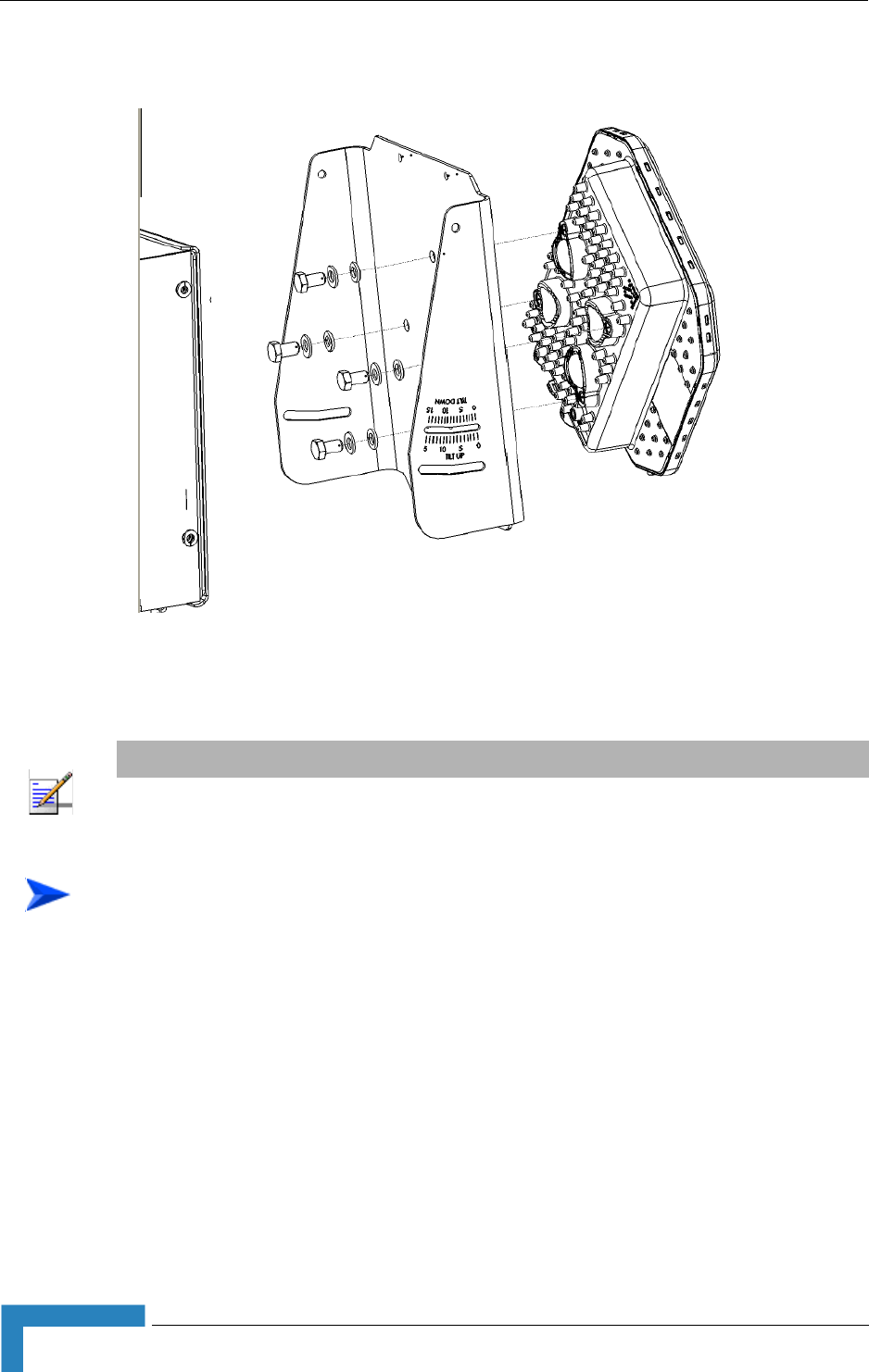
2.3.1 Attaching the SU-ODU to the Mounting Plate
1Determine the tilt direction of the SU-ODU.
2Using the M8 x 16 hex head screws and the flat washers and spring washers
supplied, attach the SU-ODU to the mounting plate as shown in Figure 2-5 in
the direction marked.
IMPORTANT
The angle at which the SU-ODU is mounted on the Wi² can be adapted depending on the location
of the Wi² unit in relation to the base station. Once attached, the mounting plate can be tilted either
up or down. Before attaching the SU-ODU to the mounting plate, determine the direction of the tilt.
To attach a BreezeMAX PRO-S ODU or BreezeACCESSSU-ODU with HW Revision E
to the mounting plate:
NOTE
BreezeACCESS SU-ODU with HW Revision E is the new, smaller size ODU available in the 5.4 and
5.8 GHz bands.
20 Installation
Chapter 2 - Hardware Installation
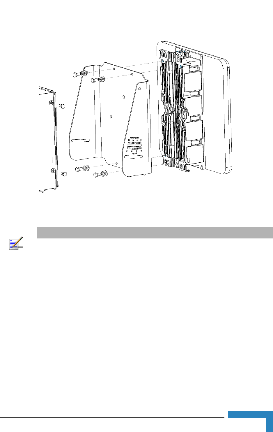
1Determine the tilt direction of the SU-ODU.
2Using the 1/4” x 1/2” hex head screws and the flat washers and spring
washers supplied, attach the SU-ODU to the mounting plate as shown in
Figure 2-6 in the direction marked.
Figure 2-5: Attaching BreezeMAX PRO-S ODU or BreezeACCESSSU-ODU with HW Revision E to
Mounting Plate
NOTE
For information about polarization refer to the relevant manual.
To attach a BreezeACCESS SU-ODU with HW Revision D or lower to the mounting
plate:
Installation
BreezeMAX Wi² and BreezeACCESS Wi² System Manual 21
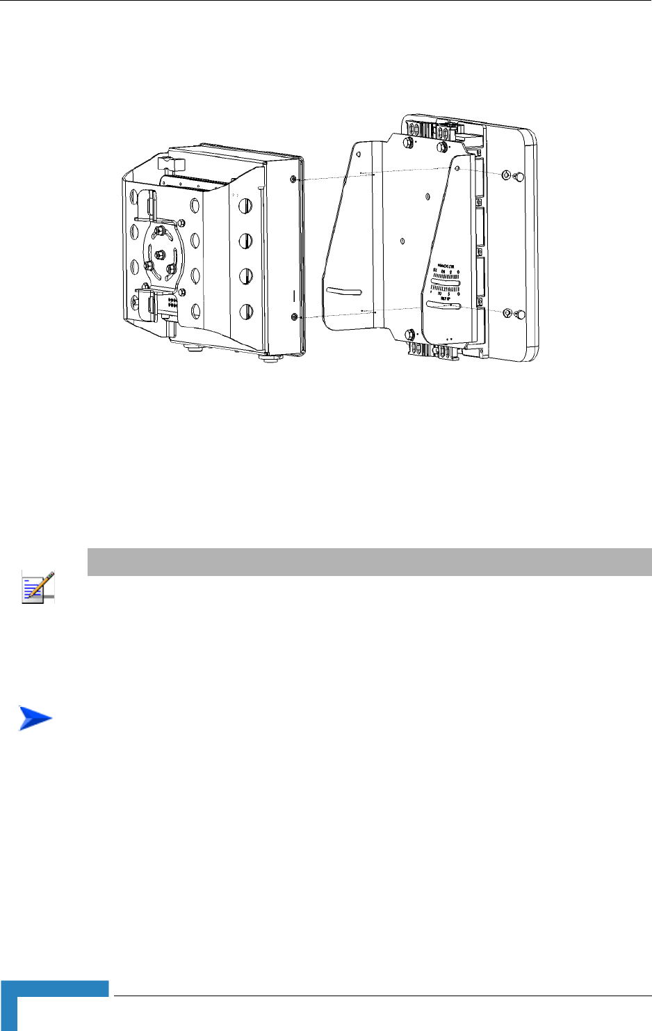
2.3.2 Attaching the Mounting Plate to the Wi² unit
1Hold the mounting plate with SU-ODU attached so the tilt label faces in the
tilt direction that you have decided upon (see Section 2.3.1).
2Using the M6 x 12 hex head screws with integral washers, attach the
mounting plate to the Wi² unit as shown in Figure 2-7.
Figure 2-6: Attaching BreezeACCESS SU-ODU with HW Revision D or lower to Mounting Plate
NOTE
Sometimes, physical circumstance require that the SU-ODU be located at a distance from the Wi²
unit and not attached to the mounting plate. For further information see the section on SU-ODU
mounting in the relevant manual.
22 Installation
Chapter 2 - Hardware Installation
3Adjust the tilt angle according the scale marked on the mounting plate and
tighten the screws.
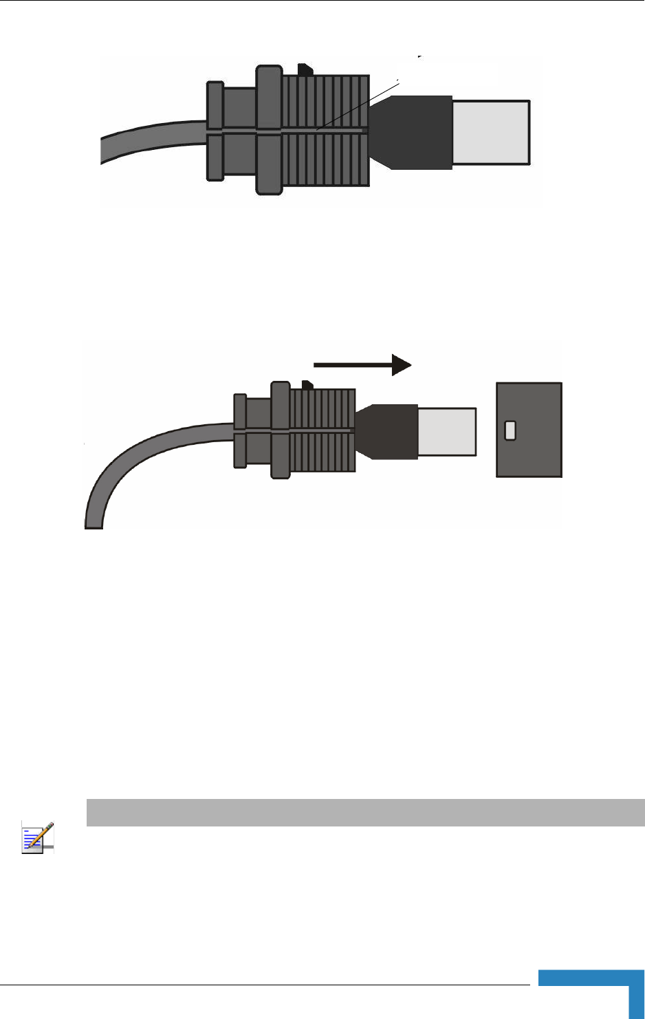
2.3.3 Connecting the Wi² unit to the SU-ODU
1The rubber sealing cap (supplied with the SU-ODU) has a special groove
allowing to insert an ethernet cable with an already assembled RJ-45
connector through the cap. To expose the groove, lightly squeeze the cap (see
Figure 2-8). Carefully insert the unshielded end of category 5E Ethernet cable
supplied through the groove.
Figure 2-7: Attaching the Mounting Plate to the Wi² Unit
NOTE
The Wi² installation kit includes a Category 5E Ethernet cable, suitable for connecting to
BreezeMAX PRO-S and BreezeACCESSHW revision E SU-ODU units. For instructions on how to
adapt the Ethernet cable for connecting to a BreezeACCESS SU-ODU with HW revision D or lower
refer to Section 2.3.3.1, “Adapting the Ethernet Cable for Connecting to BreezeACCESS SU-ODU
with HW Revision D or lower” on page 2-24
To connect the Wi² to BreezeMAX PRO-S and BreezeACCESS HW revision E
SU-ODU units:
Installation
BreezeMAX Wi² and BreezeACCESS Wi² System Manual 23
2Expose the RJ-45 connector under the sealing cap on the Ethernet cable and
connect to the SU-ODU RJ-45 connector (Figure 2-9).
3Put the sealing cap back in its place. Make sure that the small protrusion on
the side of the cap fits inside the hole on the connector's protective body.
4Connect the other end of the Ethernet cable to the SU port on the Wi² unit.
5Verify that the O-ring supplied with the service box kit is in place, attach the
service box to the unit and tighten the top nut.
6Use appropriate sealing material to protect the connection to the SU-ODU
against moisture and humidity. Use removable sealing material to enable
future access to the connector.
Figure 2-8: Sealing Cap
Figure 2-9: Connecting the SU-ODU connector and inserting the Sealing Cap
NOTE
Use high quality sealing material such as Scotch® 130C Linerless Rubber Splicing Tape from 3M to
ensure IP-67 compliant protection against dust and water.
groove

24 Installation
Chapter 2 - Hardware Installation
2.3.3.1 Adapting the Ethernet Cable for Connecting to
BreezeACCESS SU-ODU with HW Revision D or lower
The rubber sealing cap on the Category 5E Ethernet cable supplied does not suit
all SU-ODU units and sometimes has to be changed.
1Lightly squeeze the groove on the sealing cap on the Ethernet cable and
remove the sealing cap (see Figure 2-8).
2Cut the cable and remove the RJ-45 connector.
3Route the cable through the service box supplied with the SU-ODU.
4Use a crimp tool to prepare the wires, insert them into the appropriate pins as
outlined on the service box and use the crimp tool to crimp the connector.
Make sure to do the following:
Remove as small a length as possible of the external jacket of the wires.
Verify that the external jacket is well inside the service box to ensure good
sealing.
Pull back the shield drain wire before inserting the cable into the RJ-45
connector, to ensure a good connection with the connector's shield after
crimping.
5Connect the Ethernet cable to the SU-ODU RJ-45 connector.
6Make sure that the external jacket of the cable is well inside the service box to
guarantee a good seal.
7Verify that the O-ring of the service box kit is in place , attach the service box
to the unit and tighten the top nut.
To adapt the Ethernet cable for connecting to a BreezeACCESS SU-ODU with HW
Revision D or lower:
Installation
BreezeMAX Wi² and BreezeACCESS Wi² System Manual 25
2.3.4 Preparing the Power Cable
1Use a UL/CSA listed smooth circular power cable, 1.5mm to 2.5mm each.
Outer diameter 7mm to 9mm, UV resistant, temperature range -40°C to +
65°C (-40°F to +149°F) minimum. Other specifications (such as oil resistance,
no of wires) according to specific installation requirements.
2Use a cap assembly tool to unscrew the locking nut.
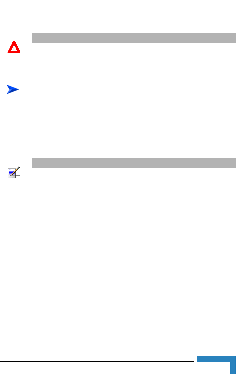
3 Thread the cable through component parts as shown in Figure 2-10.
CAUTION
Electric Shock Hazard. Only a licensed electrician should connect the power plug.
All mains used outdoors, in damp or wet conditions, should be supplied from a correctly fused
source and protected according to applicable local regulations.
To prepare the power cable:
NOTE
Figure 2-10 shows an AC power jack. The DC power jack is similar, but only has two sockets.
26 Installation
Chapter 2 - Hardware Installation
4Strip insulation from wires as shown in Figure 2-10.
5Insert bare wire ends into the terminals and fully tighten the screws. The wires
should be connected as shown below:
6Draw cable back until socket insert is correctly seated in D-shaped location in
the main body. Tighten the Gland nut. Screw back the locking ring using the
cap assembly tool.
7For an AC cable, connect a mains plug to the other end of the cable. For a DC
cable, connect the appropriate termination.
Figure 2-10: Preparing the Power Cable
AC DC
Brown Phase ~ Red +
Blue Neutral 0 Black -
Yellow/green Grounding

Installation
BreezeMAX Wi² and BreezeACCESS Wi² System Manual 27
2.3.5 Pre-Configuration and Testing
It is highly recommended that you configure the parameters of the Access Point
(AP) unit and the SU-ODU and verify proper operation of the system in the
laboratory before installing the Wi² unit.
1Set up the unit a short distance (4.5m to 7.5m) from an approved test unit,
either outdoors or indoors.
2Connect the power cable to the power socket on the unit. Connect the other
end to the mains supply.
3Check that the LED on the Wi² is green indicating that the system is working
normally.
4Using Telnet, login as outlined in Chapter 3 - "Initial Configuration" and
complete the initial configuration.
5Complete the configuration of the AP, using either Telnet or the web-based
interface as outlined in Chapter 4 - "System Configuration".
6Disconnect the cable connecting the SU-ODU to the SU port of the Wi²unit.
7Connect an SU-IDU to the SU-ODU.
8Connect a PC to the Ethernet port of the IDU and configure its parameters. For
configuration details refer to the relevant manual.
9After configuring the parameters of the AP and SU-ODU and verifying proper
operation of the system, disconnect the unit from the power source and
proceed to mount the unit as outlined in Section 2.3.6.
To configure the AP unit:
28 Installation
Chapter 2 - Hardware Installation
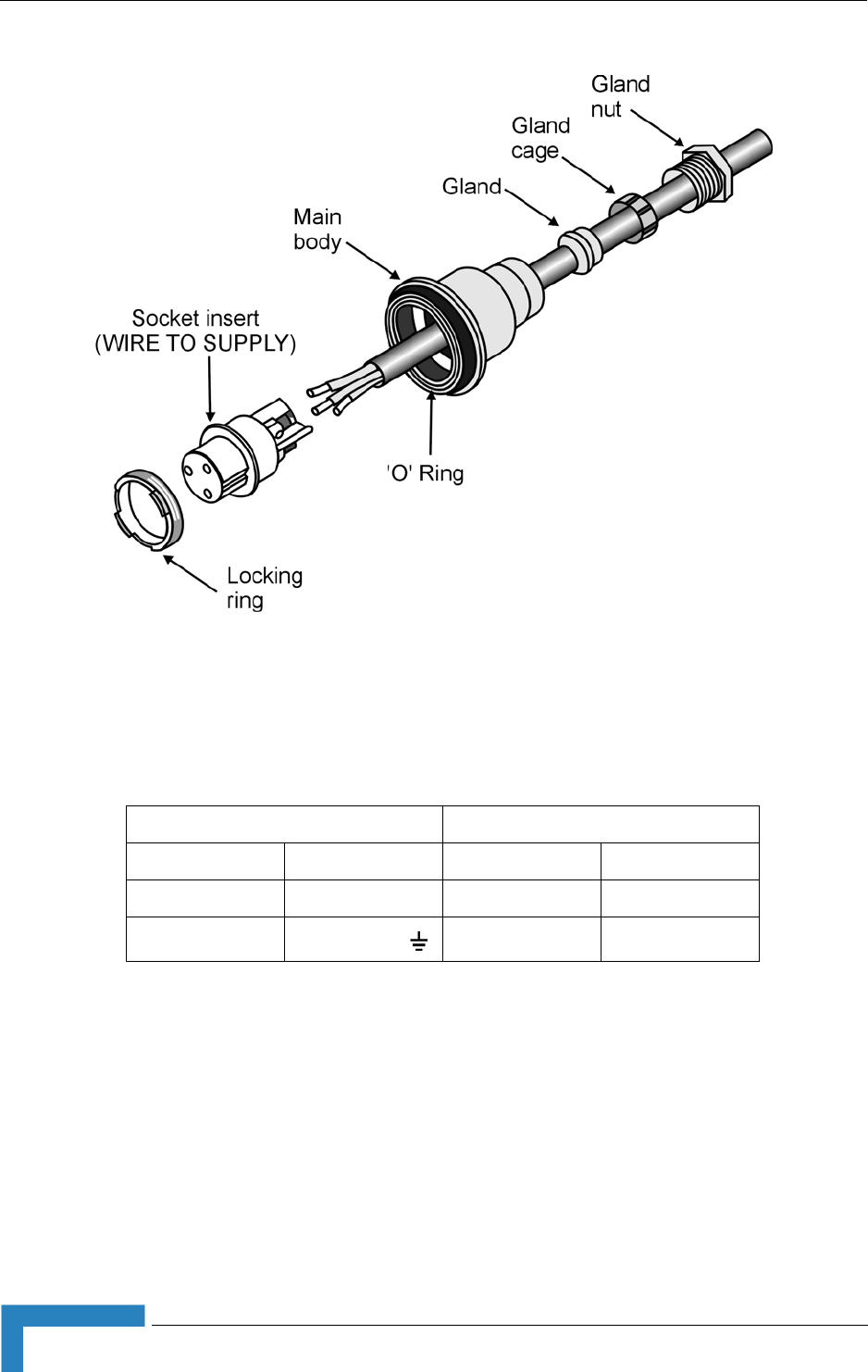
2.3.6 Mounting the Wi² Unit
1With the bottom panel of the unit facing downwards, thread the two 9/16"
wide metal bands supplied through the brackets on the sides of the unit.
2Rotate the mounting bracket, so that the Wi² faces the Base Station.
3 Secure the Wi² unit to a pole as shown in Figure 2-11.
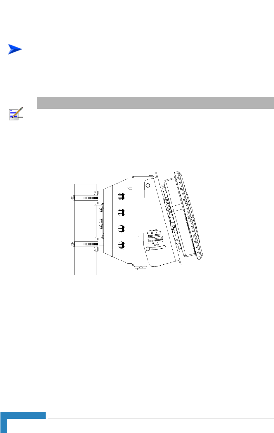
2.3.6.1 Mounting the Wi² using the Tilt Accessory
The Wi² can also be installed on a wall or on a non-vertical pole using an optional
tilt accessory kit. The tilt accessory kit ( Figure 2-12) includes:
A mounting bracket
3 metal bands for attaching the bracket to a pole
To pole mount the Wi² unit:
NOTE
The mounting bracket can be rotated up to 45o in any direction.
Figure 2-11: Pole Mounting the Wi²
Installation
BreezeMAX Wi² and BreezeACCESS Wi² System Manual 29
Screws for attaching the bracket to a wall
A 50 cm pole (diameter 6.03 cm)
Screws for attaching the pole to mounting bracket
1Place the bracket on the wall and use as a template to mark the position of the
holes to be drilled for the screws .
2Remove the bracket from the wall and drill a hole in each of the locations
marked.
3Insert anchors into the holes.
4Hold the bracket over the holes and insert a screw into each of the holes in the
bracket, and screw into the anchors in the wall. Secure the bracket to the wall,
making sure that the screw heads are as level with the bracket as possible.
Thread the metal bands provides with the tilt accessory through the slits in
the bracket and attach to the pole as shown in Figure 2-13.
Figure 2-12: Tilt Accessory Kit
To mount the tilt accessory on a wall:
To mount the tilt accessory on a non-vertical pole:
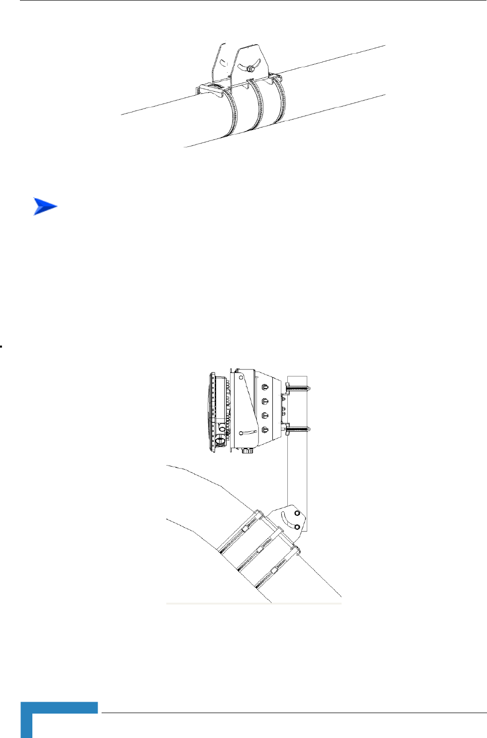
30 Installation
Chapter 2 - Hardware Installation
1Mount the tilt accessory bracket on the wall or pole as described above.
2Using the screws provided attach the pole to the tilt accessory bracket.
3Using a spirit level, adjust the angle of the pole until it is vertical and tighten
the screws to hold in place.
4Secure the Wi² to the pole as described in “Mounting the Wi² Unit” on page 28.
Figure 2-13: Mounting Tilt Accessory on Non-Vertical Pole
To mount the Wi² using the tilt accessory:
Figure 2-14: Wi² Mounting Using the Tilt Accessory

Installation
BreezeMAX Wi² and BreezeACCESS Wi² System Manual 31
2.3.7 Connecting the Grounding Cables
1Connect a grounding cable to the grounding stud on theWi² unit and tighten
the grounding screw firmly.
2Connect a grounding cable to the grounding stud on the SU-ODU and tighten
the grounding screw firmly.
3Connect the other ends of the grounding cables to a good ground (earth)
connection.
2.3.8 Connecting to Power Source
1Connect the power cable (see Section 2.3.4) to the power socket on the unit
and to the mains supply.
2Check that the LED on the Wi² is green indicating that the system is working
normally.
To connect the grounding cables:
CAUTION
Be sure that grounding is available and that it meets local and national electrical codes. For
additional lightning protection, use lightning rods, lightning arrestors, or surge suppressors.
CAUTION
The Wi² can be connected to either an AC or DC power source, or to both. By default the DC plug is
covered with a waterproof sealing cap which must be removed before connecting to the power
cable. Any socket that is NOT in use must always be protected from moisture and must be covered
with a waterproof sealing cap.

32 Installation
Chapter 2 - Hardware Installation
2.4 Post Installation Configuration of the
AP/SU-ODU
As mentioned before, it is highly recommended to complete configuration of the AP
and SU-ODU in the lab prior to installation. After initial configuration proceed to
advanced configuration via the web-based interface, Telnet, SSH, SNM web/SSH
or backhaul wireless link. See Chapter 4 - "System Configuration" for further
details.


34 Commissioning
Chapter 3 - Initial Configuration
3.1 Introduction
The Access Point (AP) unit offers a variety of management options, including a
web-based interface, Telnet, SSH, SNMP and a direct connection to the console
port.
The initial configuration steps can be made through the web browser interface or
CLI.

Initial Setup through the CLI
BreezeMAX Wi² and BreezeACCESS Wi² System Manual 35
3.2 Initial Setup through the CLI
For a description of how to use the CLI, see “Using the Command Line Interface”
on page 125. For a list of all the CLI commands and detailed information on using
the CLI, refer to “Command Groups” on page 132.
3.2.1 Configuration via Telnet
By default, use the Telnet option to configure the unit. The AP uses the default
address 192.168.1.1. This address may not be compatible with your network. You
will therefore have to use the command line interface (CLI) to assign an IP address
that is compatible with your network as described on page 36.
Use the category 5 Ethernet data cable (2 pairs crosswire) provided to connect the
SU port on the Wi² unit to your PC and Telnet the unit to start the initial setup.
3.2.2 Configuration via Console
The Wi² has a console port that enables a connection to a PC or terminal for
monitoring and configuration. Attach a VT100-compatible terminal, or a PC
running a terminal emulation program to the Wi² using an RS232 console cable.
1Connect the console cable to the serial port on a terminal, or a PC running
terminal emulation software.
2Connect the other end of the cable to the console port on the Wi² unit.
3Make sure the terminal emulation software is set as follows:-:
Select the appropriate serial port (COM port 1 or 2).
Set the data rate to 9600 baud.
Set the data format to 8 data bits, 1 stop bit, and no parity.
Set flow control to none.
Set the emulation mode to VT100.
When using HyperTerminal, select Terminal keys, not Windows keys.
4Once you have set up the terminal correctly, press the [Enter] key to initiate
the console connection. The console login screen is displayed.
To connect to the console port:

36 Commissioning
Chapter 3 - Initial Configuration
3.2.3 Initial Configuration Steps
Logging In – Enter admin for the user name. The default password is null, so just
press [Enter] at the password prompt. The CLI prompt appears displaying
Enterprise AP#.
Setting the Country Code – You must use the CLI to set the country code.
Setting the country code restricts operation of the AP to the radio channels and
transmit power levels permitted for wireless networks in the specified country.
Type exit to leave configuration mode. Then type country ? to display the list of
countries. Select the code for your country, and enter the country command
again, following by your country code (e.g., tw for Taiwan).
Setting the IP Address – By default, the AP is configured to obtain IP address
settings from a DHCP server. If a DHCP server is not available, the IP address
defaults to 192.168.1.1, which may not be compatible with your network. You will
therefore have to use the command line interface (CLI) to assign an IP address
that is compatible with your network.
Type configure to enter configuration mode, then type interface ethernet to
access the Ethernet interface-configuration mode.
First type no ip dhcp to disable DHCP client mode. Then type ip address and the
ip-address netmask gateway, where ip-address is the AP’s IP address, netmask is
the network mask for the network, and gateway is the default gateway router.
Check with your system administrator to obtain an IP address that is compatible
with your network.
Username: admin
Password:
Enterprise AP#
NOTE
For American and Canadian customers only channels 1~11 are permitted. Setting of other channels
is not possible.
Enterprise AP#country tw
Enterprise AP#
Enterprise AP#configure
Enterprise AP(config)#interface ethernet
Enterprise AP(config-if)#
Enterprise AP(if-ethernet)#no ip dhcp
Enterprise AP(if-ethernet)#ip address 192.168.2.2 255.255.255.0 192.168.2.254
Enterprise AP(if-ethernet)#

Initial Setup through the CLI
BreezeMAX Wi² and BreezeACCESS Wi² System Manual 37
After configuring the AP’s IP parameters, you can access the management
interface from anywhere within the attached network. The command line interface
can also be accessed using Telnet from any computer attached to the network.
NOTE
Command examples shown later in this manual use the console prompt to Enterprise AP.
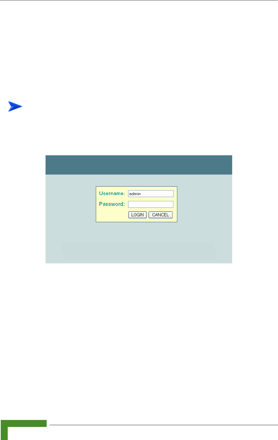
38 Commissioning
Chapter 3 - Initial Configuration
3.3 Logging In
There are a few basic steps you need to complete to connect the AP to your
corporate network, and provide network access to wireless clients.
The AP can be managed by any computer using a web browser (Internet Explorer
5.0 or above, or Netscape 6.2 or above).
1Enter the default IP address http://192.168.1.1. Figure 3-1 is displayed.
2Enter the username admin.
3The password is null, so leave blank and click LOGIN.
4The home page (Figure 3-2) is displayed.
To Login:
Figure 3-1: Login
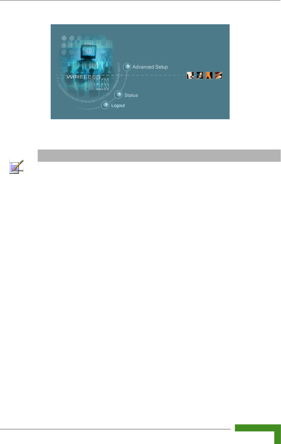

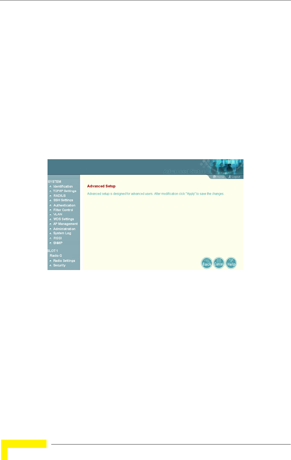
42 Operation
Chapter 4 - System Configuration
4.1 Introduction
Before continuing with advanced configuration, first complete the initial
configuration steps described in Chapter 3 to set up an IP address for the Access
Point (AP) unit.
The AP unit can be managed by any computer using a web browser (Internet
Explorer 5.0 or above, or Netscape 6.2 or above). Enter the configured IP address
of the AP unit, or use the default address: http://192.168.1.1.
Enter the default user name admin in the Log In Dialog Box (Figure 3-1) and click
LOGIN. Select Advanced Setup from the menu on the home page. Figure 4-1 is
displayed.
The information in this chapter is organized to reflect the structure of the web
screens for easy reference. However, it is recommended that you configure a user
name and password as the first step under Administration to control management
access to this device (Section 4.2.10).
Figure 4-1: Advanced Setup

Advanced Configuration
BreezeMAX Wi² and BreezeACCESS Wi² System Manual 43
4.2 Advanced Configuration
The Advanced Configuration pages include the following options.
Table 4-1: Menu
Menu Description Page
System Configures basic administrative and client access 44
Identification Specifies the host name 44
TCP / IP Settings Configures the IP address, subnet mask, gateway, and domain name servers 45
RADIUS Configures the RADIUS server for wireless client authentication and accounting 48
SSH Settings Configures Secure Shell management access 51
Authentication Configures 802.1X client authentication, with an option for MAC address
authentication
53
Filter Control Filters communications between wireless clients, access to the management
interface from wireless clients, and traffic matching specific Ethernet protocol
types
57
VLAN Enables VLAN support and sets the management VLAN ID 60
WDS Settings Not applicable for current release 62
AP Management Configures access to management interfaces 62
Administration Configures user name and password for management
access; upgrades software
from local file, FTP or TFTP server;
resets configuration settings to factory
defaults; and resets the AP
64
System Log Controls logging of error messages; sets the system clock via SNTP server or
manual configuration
70
RSSI Not applicable for current release 74
SNMP Configures SNMP settings 75
Radio Interface G Configures the IEEE 802.11g interface 81
Radio Settings Configures common radio signal parameters and other settings for each VAP
interface
81
Security Enables each VAP interface, sets the SSID, and configures wireless security 98
Status Displays information about the access point and wireless clients 116
AP Status Displays configuration settings for the basic system and the wireless interface 116
Station Status Shows the wireless clients currently associated with the access point 118
Event Logs Shows log messages stored in memory 120

44 Operation
Chapter 4 - System Configuration
4.2.1 System Identification
The system name can be left with the default setting. However, modifying this
parameter enables you to easily identify different devices in your network.
System Name – An alias for the AP, enabling the device to be uniquely identified
on the network. (Default: BlueSecure BSAP-1600; Range: 1-32 characters)
NOTE
This chapter may include references to features that are not applicable to the current release such as
Radio A, WDS Settings and RSSI.
Figure 4-2: Identification

Advanced Configuration
BreezeMAX Wi² and BreezeACCESS Wi² System Manual 45
4.2.1.0.1 CLI Commands for System Identification
Enter the global configuration mode, and use the system name command to
specify a new system name. Return to the Exec mode, and use the show system
command to display the changes to the system identification settings.
4.2.2 TCP / IP Settings
Configuring the AP with an IP address expands your ability to manage the AP. A
number of features depend on IP addressing to operate.
Enterprise AP#config 135
Enter configuration commands, one per line.
Enterprise AP(config)#system name R&D 142
Enterprise AP(config)#end 135
Enterprise AP#show system 149
System Information
==============================================================
Serial Number : 0000000000
System Up time : 2 days, 4 hours, 33 minutes, 38 seconds
System Name : R&D
System Location :
System Contact : Contact
System Country Code
System Country Code
Radio G MAC Address : 00-12-CF-12-34-95
IP Address : 192.168.1.2
Subnet Mask : 255.255.255.0
Default Gateway : 192.168.1.254
VLAN State : DISABLED
Management VLAN ID(AP): 1
IAPP State : ENABLED
DHCP Client : DISABLED
HTTP Server : ENABLED
HTTP Server Port : 80
HTTP Session Timeout : 300 sec(s)
HTTPS Server : ENABLED
HTTPS Server Port : 443
Slot Status : 802.11g only
Boot Rom Version : v2.1.6
Software Version : v4.3.3.8b02
SSH Server : ENABLED
SSH Server Port : 22
Telnet Server : ENABLED
DHCP Relay : DISABLED
==============================================================
Enterprise AP#
NOTE
You can use the web browser interface to access IP addressing only if the AP already has an IP
address that is accessible through your network.
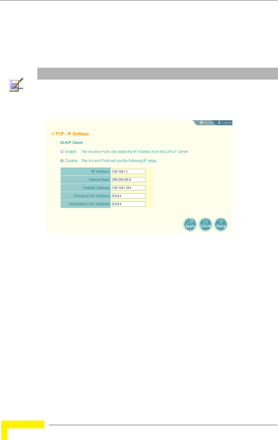
46 Operation
Chapter 4 - System Configuration
By default, the AP is automatically configured with IP settings from a Dynamic
Host Configuration Protocol (DHCP) server. However, if you are not using a DHCP
server to configure IP addressing, use the CLI to manually configure the initial IP
values (see page 36). Once you have network access to the AP, you can use the
web browser interface to modify the initial IP configuration, if necessary.
DHCP Client (Enable) – Select this option to obtain the IP settings for the AP from a
DHCP (Dynamic Host Configuration Protocol) server. The IP address, subnet
mask, default gateway, and Domain Name Server (DNS) address are dynamically
assigned to the AP by the network DHCP server. (Default: Enabled)
DHCP Client (Disable) – Select this option to manually configure a static address
for the AP.
IP Address: The IP address of the AP. Valid IP addresses consist of four
decimal numbers, 0 to 255, separated by periods.
Subnet Mask: The mask that identifies the host address bits used for routing
to specific subnets.
NOTE
If there is no DHCP server on your network, or DHCP fails, the AP will automatically start up with a
default IP address of 192.168.1.1.
Figure 4-3: TCP/IP Settings

Advanced Configuration
BreezeMAX Wi² and BreezeACCESS Wi² System Manual 47
Default Gateway: The default gateway is the IP address of the router for the
AP, which is used if the requested destination address is not on the local
subnet.
If you have management stations, DNS, RADIUS, or other network servers
located on another subnet, type the IP address of the default gateway router in
the text field provided. Otherwise, leave the address as all zeros (0.0.0.0).
Primary and Secondary DNS Address: The IP address of Domain Name Servers
on the network. A DNS maps numerical IP addresses to domain names and
can be used to identify network hosts by familiar names instead of the IP
addresses.
If you have one or more DNS servers located on the local network, type the IP
addresses in the text fields provided. Otherwise, leave the addresses as all
zeros (0.0.0.0).
4.2.2.0.1 CLI Commands for TCP/IP Settings
From the global configuration mode, enter the interface configuration mode with
the interface ethernet command. Use the ip dhcp command to enable the DHCP
client, or no ip dhcp to disable it. To manually configure an address, specify the
new IP address, subnet mask, and default gateway using the ip address
command. To specify DNS server addresses use the dns server command and use
the show interface ethernet command from the Exec mode to display the
current IP settings.
Enterprise AP(config)#interface ethernet 204
Enter Ethernet configuration commands, one per line.
Enterprise AP(if-ethernet)#no ip dhcp 206
Enterprise AP(if-ethernet)#ip address 192.168.1.2
255.255.255.0 192.168.1.253 205
Enterprise AP(if-ethernet)#dns primary-server 192.168.1.55 204
Enterprise AP(if-ethernet)#dns secondary-server 10.1.0.55 204
Enterprise AP(config)#end 135
Enterprise AP#show interface ethernet 207
Ethernet Interface Information
========================================
IP Address : 192.168.1.2
Subnet Mask : 255.255.255.0
Default Gateway : 192.168.1.253
Primary DNS : 192.168.1.55
Secondary DNS : 10.1.0.55
Admin status : Up
Operational status : Up
========================================
Enterprise AP#

48 Operation
Chapter 4 - System Configuration
4.2.3 RADIUS
Remote Authentication Dial-in User Service (RADIUS) is an authentication
protocol that uses software running on a central server to control access to
RADIUS-aware devices on the network. An authentication server contains a
database of user credentials for each user that requires access to the network.
A primary RADIUS server must be specified for the AP to implement IEEE 802.1X
network access control and WiFi Protected Access (WPA) wireless security. A
secondary RADIUS server may also be specified as a backup should the primary
server fail or become inaccessible.
In addition, the configured RADIUS server can also act as a RADIUS Accounting
server and receive user-session accounting information from the AP. RADIUS
Accounting can be used to provide valuable information on user activity in the
network.
NOTE
This manual assumes that you have already configured RADIUS server(s) to support the AP.
Configuration of RADIUS server software is beyond the scope of this manul, refer to the
documentation provided with the RADIUS server software.
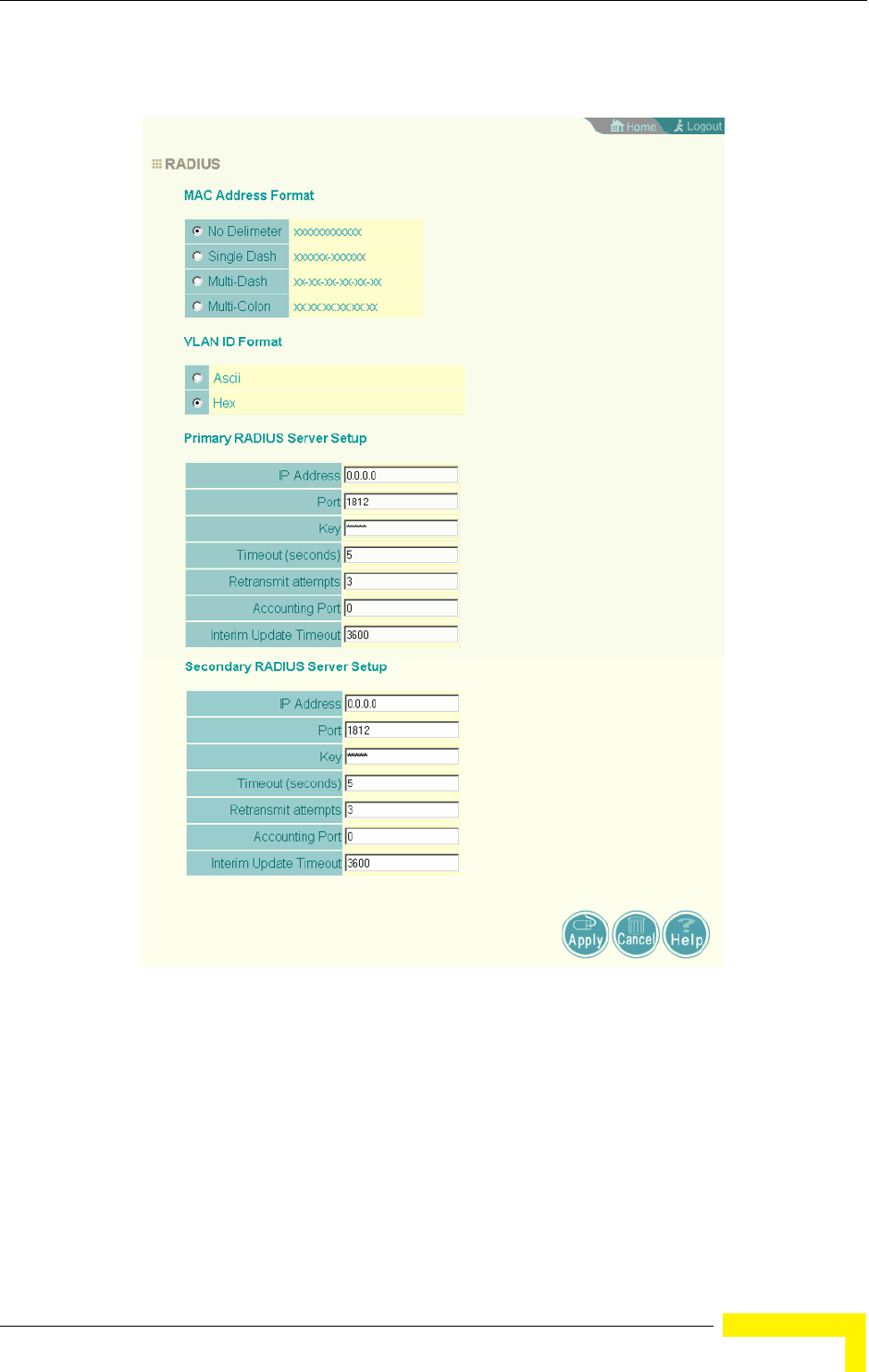
Advanced Configuration
BreezeMAX Wi² and BreezeACCESS Wi² System Manual 49
MAC Address Format – MAC addresses can be specified in one of four formats,
using no delimiter, with a single dash delimiter, with multiple dash delimiters,
and with multiple colon delimiters.
VLAN ID Format – A VLAN ID (a number between 1 and 4094) can be assigned to
each client after successful authentication using IEEE 802.1X and a central
RADIUS server. The user VLAN IDs must be configured on the RADIUS server for
Figure 4-4: RADIUS

50 Operation
Chapter 4 - System Configuration
each user authorized to access the network. VLAN IDs can be entered as
hexadecimal numbers or as ASCII strings.
Primary Radius Server Setup – Configure the following settings to use RADIUS
authentication on the AP.
Radius Status: Enabling Radius Status allows the settings of RADIUS
authentication. (Default: Enable)
IP Address: Specifies the IP address or host name of the RADIUS server.
Port: The UDP port number used by the RADIUS server for authentication
messages. (Range: 1024-65535; Default: 1812)
Key: A shared text string used to encrypt messages between the AP and the
RADIUS server. Be sure that the same text string is specified on the RADIUS
server. Do not use blank spaces in the string. (Maximum length: 255
characters)
Timeout: Number of seconds the AP waits for a reply from the RADIUS server
before resending a request. (Range: 1-60 seconds; Default: 5)
Retransmit attempts: The number of times the AP tries to resend a request to
the RADIUS server before authentication fails. (Range: 1-30; Default: 3)
Accounting Port: The RADIUS Accounting server UDP port used for accounting
messages. (Range: 0 or 1024-65535; Default: 0, disabled)
Interim Update Timeout: The interval between transmitting accounting updates
to the RADIUS server. (Range: 60-86400; Default: 3600 seconds)
Secondary Radius Server Setup – Configure a secondary RADIUS server to provide
a backup in case the primary server fails. The AP uses the secondary server if the
primary server fails or becomes inaccessible. Once the AP switches over to the
secondary server, it periodically attempts to establish communication again with
primary server. If communication with the primary server is re-established, the
secondary server reverts to a backup role.
NOTE
For the Timeout and Retransmit attempts fields, accept the default values unless you experience
problems connecting to the RADIUS server over the network.

Advanced Configuration
BreezeMAX Wi² and BreezeACCESS Wi² System Manual 51
4.2.3.0.1 CLI Commands for RADIUS
From the global configuration mode, use the radius-server address command to
specify the address of the primary or secondary RADIUS servers. (The following
example configures the settings for the primary RADIUS server.) Configure the
other parameters for the RADIUS server. Then use the show radius command
from the Exec mode to display the current settings for the primary and secondary
RADIUS servers.
4.2.4 SSH Settings
Telnet is a remote management tool that can be used to configure the AP from
anywhere in the network. However, Telnet is not secure from hostile attacks. The
Secure Shell (SSH) can act as a secure replacement for Telnet. The SSH protocol
uses generated public keys to encrypt all data transfers passing between the AP
and SSH-enabled management station clients and ensures that data traveling
over the network arrives unaltered. Clients can then securely use the local user
name and password for access authentication.
Enterprise AP(config)#radius-server address 192.168.1.25 185
Enterprise AP(config)#radius-server port 181 186
Enterprise AP(config)#radius-server key green 186
Enterprise AP(config)#radius-server timeout 10 187
Enterprise AP(config)#radius-server retransmit 5 186
Enterprise AP(config)#radius-server port-accounting 1813 187
Enterprise AP(config)#radius-server timeout-interim 500 188
Enterprise AP(config)#exit
Enterprise AP#show radius 189
Radius Server Information
========================================
IP : 192.168.1.25
Port : 181
Key : *****
Retransmit : 5
Timeout : 10
Radius MAC format : no-delimiter
Radius VLAN format : HEX
========================================
Radius Secondary Server Information
========================================
IP : 0.0.0.0
Port : 1812
Key : *****
Retransmit : 3
Timeout : 5
Radius MAC format : no-delimiter
Radius VLAN format : HEX
========================================
Enterprise AP#
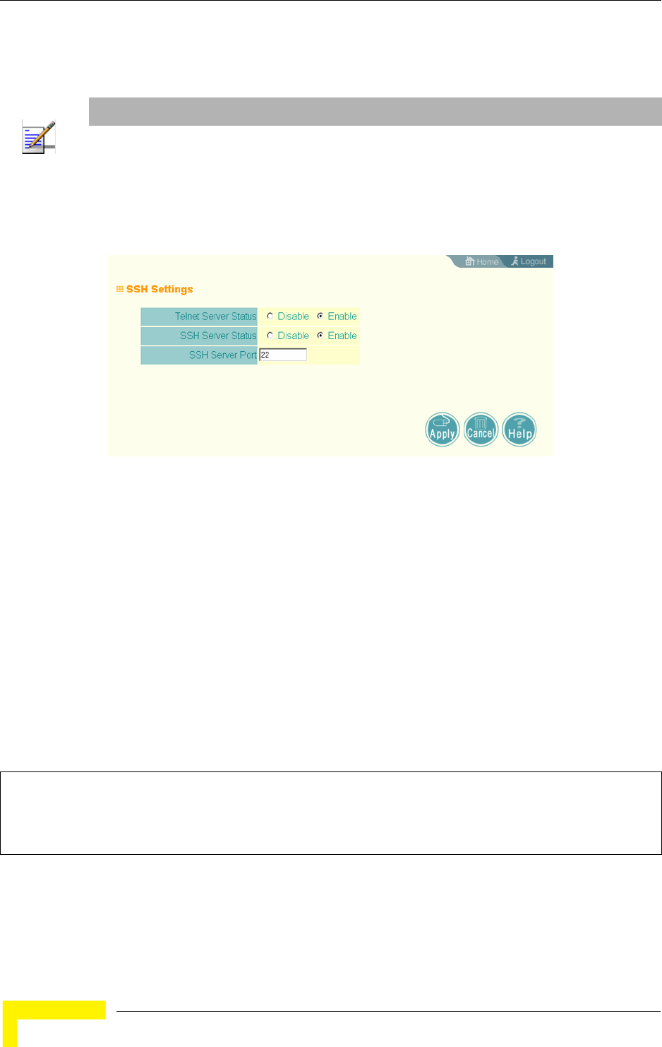
52 Operation
Chapter 4 - System Configuration
SSH client software needs to be installed on the management station to access the
AP for management via the SSH protocol.
4.2.4.1 SSH Settings
Telnet Server Status – Enables or disables the Telnet server. (Default: Enabled)
SSH Server Status – Enables or disables the SSH server. (Default: Enabled)
SSH Server Port – Sets the UDP port for the SSH server. (Range: 1-65535;
Default: 22)
4.2.4.1.1 CLI Commands for SSH
To enable the SSH server, use the ip ssh-server enable command from the CLI
Ethernet interface configuration mode. To set the SSH server UDP port, use the ip
ssh-server port command. To view the current settings, use the show system
command from the CLI Exec mode (not shown in the following example).
NOTE
The AP supports only SSH version 2.0.
After boot up, the SSH server needs about two minutes to generate host encryption keys. The
SSH server is disabled while the keys are being generated.
Figure 4-5: SSH Settings
Enterprise AP(if-ethernet)#no ip telnet-server 144
Enterprise AP(if-ethernet)#ip ssh-server enable 143
Enterprise AP(if-ethernet)#ip ssh-server port 1124 144
Enterprise AP(if-ethernet)#exit
Enterprise AP(config)#

Advanced Configuration
BreezeMAX Wi² and BreezeACCESS Wi² System Manual 53
4.2.5 Authentication
Wireless clients can be authenticated for network access by checking their MAC
address against the local database configured on the AP, or by using a database
configured on a central RADIUS server. Alternatively, authentication can be
implemented using the IEEE 802.1X network access control protocol.
A client’s MAC address provides relatively weak user authentication, since MAC
addresses can be easily captured and used by another station to break into the
network. Using 802.1X provides more robust user authentication using user
names and passwords or digital certificates. You can configure the access point to
use both MAC address and 802.1X authentication, with client station MAC
authentication occurring prior to IEEE 802.1X authentication. However, it is
better to choose one or the other, as appropriate.
Take note of the following points before configuring MAC address or 802.1X
authentication:
Use MAC address authentication for a small network with a limited number of
users. MAC addresses can be manually configured on the AP itself without the
need to set up a RADIUS server, but managing a large number of MAC
addresses across many APs is very cumbersome. A RADIUS server can be used
to centrally manage a larger database of user MAC addresses.
Use IEEE 802.1X authentication for networks with a larger number of users
and where security is the most important issue. When using 802.1X
authentication, a RADIUS server is required in the wired network to centrally
manage the credentials of the wireless clients. It also provides a mechanism
for enhanced network security using dynamic encryption key rotation or WiFi
Protected Access (WPA).
The AP can also operate in a 802.1X supplicant mode. This enables the AP
itself to be authenticated with a RADIUS server using a configured MD5 user
name and password. This prevents rogue APs from gaining access to the
network.
NOTE
If you configure RADIUS MAC authentication together with 802.1X, RADIUS MAC address
authentication is performed prior to 802.1X authentication. If RADIUS MAC authentication
succeeds, then 802.1X authentication is performed. If RADIUS MAC authentication fails, 802.1X
authentication is not performed.

54 Operation
Chapter 4 - System Configuration
MAC Authentication – You can configure a list of the MAC addresses for wireless
clients that are authorized to access the network. This provides a basic level of
authentication for wireless clients attempting to gain access to the network. A
database of authorized MAC addresses can be stored locally on the AP or remotely
on a central RADIUS server. (Default: Disabled)
Disabled: No checks are performed on an associating station’s MAC address.
Local MAC: The MAC address of the associating station is compared against
the local database stored on the AP. Use the Local MAC Authentication section
of this web page to set up the local database, and configure all APs in the
wireless network service area with the same MAC address database.
Radius MAC: The MAC address of the associating station is sent to a
configured RADIUS server for authentication. When using a RADIUS
authentication server for MAC address authentication, the server must first be
configured in the Radius window (see “RADIUS” on page 48). The database of
MAC addresses and filtering policy must be defined in the RADIUS server.
Figure 4-6: Authentication

Advanced Configuration
BreezeMAX Wi² and BreezeACCESS Wi² System Manual 55
802.1X Supplicant – The AP can also operate in a 802.1X supplicant mode. This
enables the access point itself to be authenticated with a RADIUS server using a
configured MD5 user name and password. This prevents rogue APs from gaining
access to the network.
Local MAC Authentication – Configures the local MAC authentication database.
The MAC database provides a mechanism to take certain actions based on a
wireless client’s MAC address. The MAC list can be configured to allow or deny
network access to specific clients.
System Default: Specifies a default action for all unknown MAC addresses
(that is, those not listed in the local MAC database).
Deny: Blocks access for all MAC addresses except those listed in the local
database as “Allow.”
Allow: Permits access for all MAC addresses except those listed in the local
database as “Deny.”
MAC Authentication Settings: Enters specified MAC addresses and permissions
into the local MAC database.
MAC Address: Physical address of a client. Enter six pairs of hexadecimal
digits separated by hyphens; for example, 00-90-D1-12-AB-89.
Permission: Select Allow to permit access or Deny to block access. If Delete
is selected, the specified MAC address entry is removed from the database.
Update: Enters the specified MAC address and permission setting into the
local database.
MAC Authentication Table: Displays current entries in the local MAC database.
4.2.5.0.1 CLI Commands for Local MAC Authentication
Use the mac-authentication server command from the global configuration
mode to enable local MAC authentication. Use the mac-authentication
session-timeout command to set the authentication interval to enable web-based
authentication for service billing. Set the default action for MAC addresses not in
the local table using the address filter default command, then enter MAC
NOTE
MAC addresses on the RADIUS server can be entered in four different formats (see “RADIUS”
on page 48).

56 Operation
Chapter 4 - System Configuration
addresses in the local table using the address filter entry command. To remove
an entry from the table, use the address filter delete command. To display the
current settings, use the show authentication command from the Exec mode.
4.2.5.0.2 CLI Commands for RADIUS MAC Authentication
Use the mac-authentication server command from the global configuration
mode to enable remote MAC authentication. Set the timeout value for
re-authentication using the mac- authentication session-timeout command. Be
sure to also configure connection settings for the RADIUS server (not shown in the
Enterprise AP(config)#mac-authentication server local 196
Enterprise AP(config)#mac-authentication session-timeout 5 196
Enterprise AP(config)#address filter default denied 194
Enterprise AP(config)#address filter entry
00-70-50-cc-99-1a denied 195
Enterprise AP(config)#address filter entry
00-70-50-cc-99-1b allowed
Enterprise AP(config)#address filter entry
00-70-50-cc-99-1c allowed
Enterprise AP(config)#address filter delete
00-70-50-cc-99-1c 195
Enterprise AP(config)#exit
Enterprise AP#show authentication 193
Authentication Information
===========================================================
MAC Authentication Server : LOCAL
MAC Auth Session Timeout Value : 0 min
802.1x supplicant : DISABLED
802.1x supplicant user : EMPTY
802.1x supplicant password : EMPTY
Address Filtering : DENIED
System Default : ALLOW addresses not found in filter table.
Filter Table
MAC Address Status
----------------- ----------
00-70-50-cc-99-1a DENIED
00-70-50-cc-99-1b ALLOWED
=========================================================
Enterprise AP#

Advanced Configuration
BreezeMAX Wi² and BreezeACCESS Wi² System Manual 57
following example). To display the current settings, use the show authentication
command from the Exec mode.
4.2.5.0.3 CLI Command for 802.1x Supplicant
To configure the AP to operate as a 802.1X supplicant, first use the 802.1X
supplicant user command to set a user name and password for the AP, then use
the 802.1X supplicant command to enable the feature. To display the current
settings, use the show authentication command from the Exec mode (not shown
in the following example)
4.2.6 Filter Control
The AP can employ network traffic frame filtering to control access to network
resources and increase security. You can prevent communications between
wireless clients and prevent AP management from wireless clients. You can also
block specific Ethernet traffic from being forwarded by the AP.
Enterprise AP(config)#mac-authentication server remote 196
Enterprise AP(config)#mac-authentication
session-timeout 300 196
Enterprise AP(config)#exit
Enterprise AP#show authentication 193
Authentication Information
===========================================================
MAC Authentication Server : REMOTE
MAC Auth Session Timeout Value : 300 min
802.1x supplicant : DISABLED
802.1x supplicant user : EMPTY
802.1x supplicant password : EMPTY
Address Filtering : DENIED
System Default : DENY addresses not found in filter table.
Filter Table
MAC Address Status
----------------- ----------
00-70-50-cc-99-1a DENIED
00-70-50-cc-99-1b ALLOWED
=========================================================
Enterprise AP#
Enterprise AP(config)#802.1X supplicant user secureAP dot1xpass 192
Enterprise AP(config)#802.1X supplicant 192
Enterprise AP(config)#
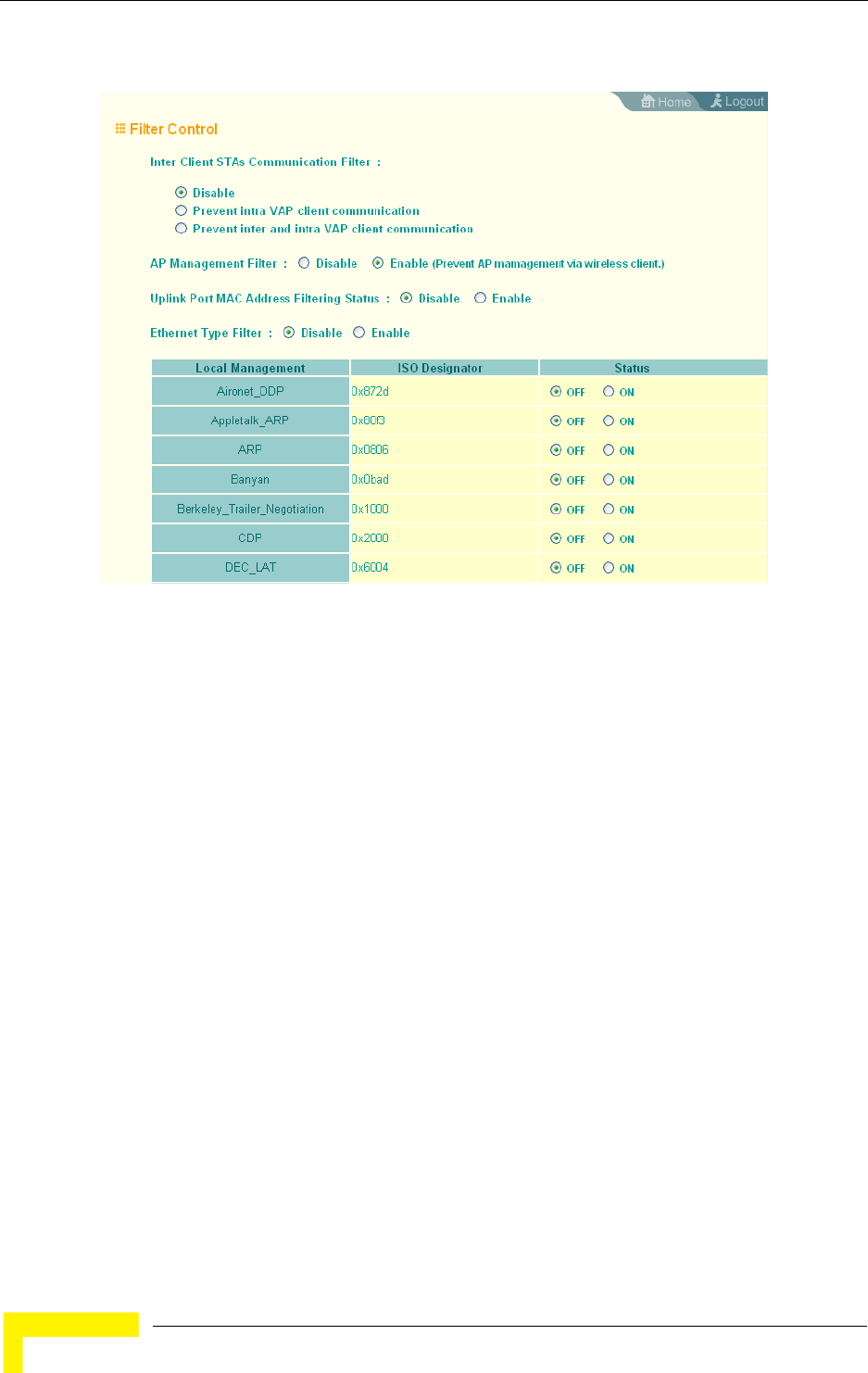
58 Operation
Chapter 4 - System Configuration
Inter Client STAs Communication Filter – Sets the global mode for
wireless-to-wireless communications between clients associated to Virtual AP
(VAP) interfaces on the AP. (Default: Disabled)
Disabled: All clients can communicate with each other through the access
point.
Prevent Intra VAP client communication: When enabled, clients associated with
a specific VAP interface cannot establish wireless communications with each
other. Clients can communicate with clients associated to other VAP
interfaces.
Prevent Inter and Intra VAP client communication: When enabled, clients cannot
establish wireless communications with any other client, either those
associated to the same VAP interface or any other VAP interface.
AP Management Filter – Controls management access to the AP from wireless
clients. Management interfaces include the web, Telnet, or SNMP.
(Default: Enabled)
Figure 4-7: Filter Control

Advanced Configuration
BreezeMAX Wi² and BreezeACCESS Wi² System Manual 59
Disabled: Allows management access from wireless clients.
Enabled: Blocks management access from wireless clients.
Uplink Port MAC Address Filtering Status – Prevents traffic with specified source
MAC addresses from being forwarded to wireless clients through the AP. You can
add a maximum of four MAC addresses to the filter table. (Default: Disabled)
MAC Address: Specifies a MAC address to filter, in the form xx-xx-xx-xx-xx-xx.
Permission: Adds or deletes a MAC address from the filtering table.
Ethernet Type Filter – Controls checks on the Ethernet type of all incoming and
outgoing Ethernet packets against the protocol filtering table. (Default: Disabled)
Disabled: AP does not filter Ethernet protocol types.
Enabled: AP filters Ethernet protocol types based on the configuration of
protocol types in the filter table. If the status of a protocol is set to ON, the
protocol is filtered from the AP.
Ethernet Type Filter – Enables or disables Ethernet filtering on the port. (Default:
Disabled)
4.2.6.0.1 CLI Commands for Filtering
Use the filter ap-manage command to restrict management access from wireless
clients. To configure Ethernet protocol filtering, use the filter ethernet-type
enable command to enable filtering and the filter ethernet-type protocol
command to define the protocols that you want to filter. To remove an entry from
NOTE
Ethernet protocol types not listed in the filtering table are always forwarded by the AP.

60 Operation
Chapter 4 - System Configuration
the table, use the address filter delete command. To display the current settings,
use the show filters command from the Exec mode.
4.2.7 VLAN
The AP can employ VLAN tagging support to control access to network resources
and increase security. VLANs separate traffic passing between the AP, associated
clients, and the wired network. There can be a VLAN assigned to each associated
client, a default VLAN for each VAP (Virtual Access Point) interface, and a
management VLAN for the AP.
Note the following points about the AP’s VLAN support:
The management VLAN is for managing the AP through remote management
tools, such as the web interface, SSH, SNMP, or Telnet. The AP only accepts
management traffic that is tagged with the specified management VLAN ID.
All wireless clients associated to the AP are assigned to a VLAN. If IEEE
802.1X is being used to authenticate wireless clients, specific VLAN IDs can be
configured on the RADIUS server to be assigned to each client. If a client is not
assigned to a specific VLAN or if 802.1X is not used, the client is assigned to
the default VLAN for the VAP interface with which it is associated. The AP only
allows traffic tagged with assigned VLAN IDs or default VLAN IDs to access
clients associated on each VAP interface.
When VLAN support is enabled on the AP, traffic passed to the wired network
is tagged with the appropriate VLAN ID, either an assigned client VLAN ID,
default VLAN ID, or the management VLAN ID. Traffic received from the wired
Enterprise AP(config)#filter ap-manage 198
Enterprise AP(config)#filter uplink enable 198
Enterprise AP(config)#filter uplink add 00-12-34-56-78-9a 199
Enterprise AP(config)#filter ethernet-type enable 199
Enterprise AP(config)#filter ethernet-type protocol ARP 200
Enterprise AP(config)#exit
Enterprise AP#show filters 201
Protocol Filter Information
=========================================================
Local AP :ENABLED
AP Management :ENABLED
Ethernet Type Filter :ENABLED
Enabled Protocol Filters
---------------------------------------------------------
Protocol: ARP ISO: 0x0806
=========================================================
Enterprise AP#
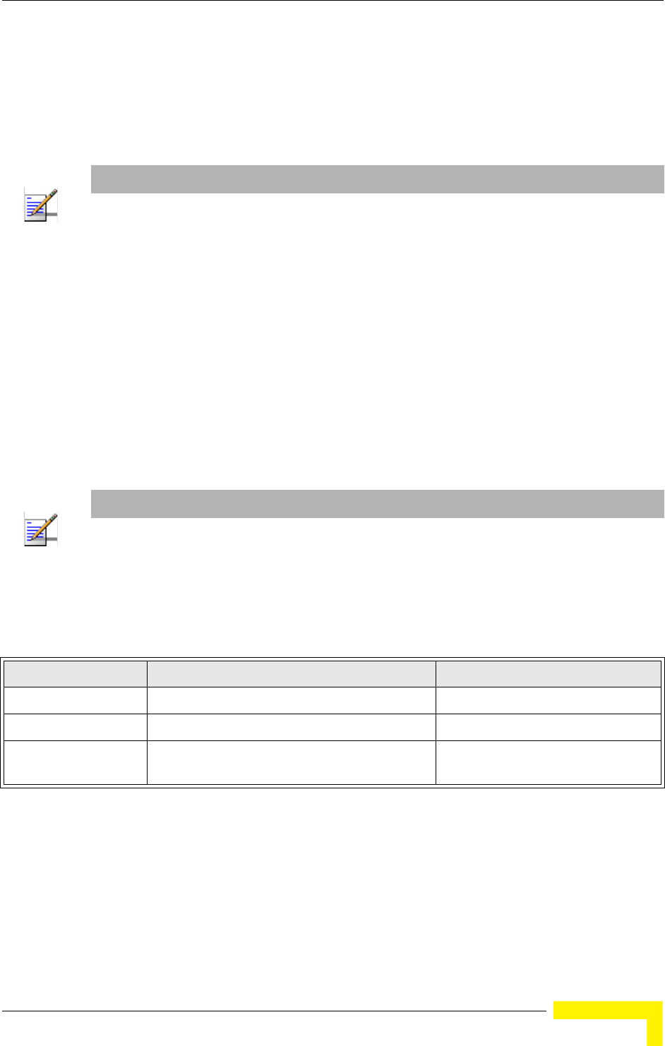
Advanced Configuration
BreezeMAX Wi² and BreezeACCESS Wi² System Manual 61
network must also be tagged with one of these known VLAN IDs. Received
traffic that has an unknown VLAN ID or no VLAN tag is dropped.
When VLAN support is disabled, the AP does not tag traffic passed to the wired
network and ignores the VLAN tags on any received frames.
Using IEEE 802.1X and a central RADIUS server, up to 64 VLAN IDs can be
mapped to specific wireless clients, allowing users to remain within the same
VLAN as they move around a campus site. This feature can also be used to control
access to network resources from clients, thereby improving security.
A VLAN ID (1-4094) can be assigned to a client after successful IEEE 802.1X
authentication. The client VLAN IDs must be configured on the RADIUS server for
each user authorized to access the network. If a client does not have a configured
VLAN ID on the RADIUS server, the AP assigns the client to the configured default
VLAN ID for the VAP interface.
When setting up VLAN IDs for each user on the RADIUS server, be sure to use the
RADIUS attributes and values as indicated Table 4-2.
VLAN IDs on the RADIUS server can be entered as hexadecimal digits or a string
(see “radius-server vlan-format” on page 189).
NOTE
Before enabling VLAN tagging on the AP, be sure to configure the backhaul system to support
tagged VLAN frames from the AP’s management VLAN ID, default VLAN IDs, and other client
VLAN IDs. Otherwise, connectivity to the AP will be lost when you enable the VLAN feature.
NOTE
When using IEEE 802.1X to dynamically assign VLAN IDs, the AP must have 802.1X authentication
enabled and a RADIUS server configured. Wireless clients must also support 802.1X client
software.
Table 4-2: RADIUS Attributes
Number RADIUS Attribute Value
64 Tunnel-Type VLAN (13)
65 Tunnel-Medium-Type 802
81 Tunnel-Private-Group-ID VLANID
(1 to 4094 as hexadecimal or string)
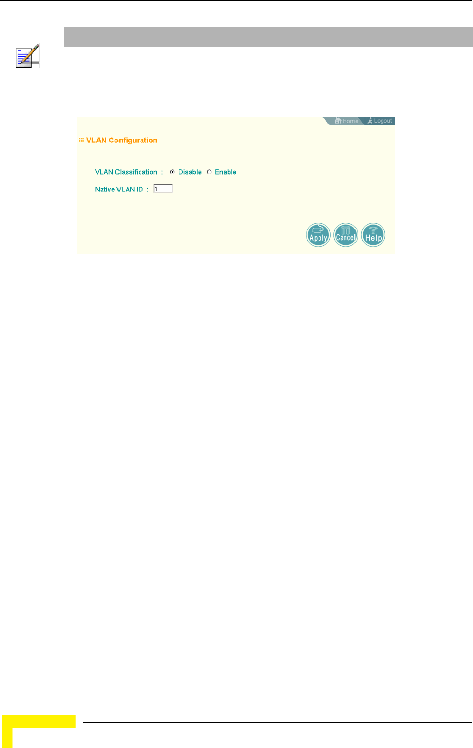
62 Operation
Chapter 4 - System Configuration
VLAN Classification – Enables or disables VLAN tagging support on the AP.
Native VLAN ID – The VLAN ID that traffic must have to be able to manage the AP.
(Range 1-4094; Default: 1)
4.2.8 WDS Settings
WDS Settings is not applicable for the current release.
4.2.9 AP Management
The Web, Telnet, and SNMP management interfaces are enabled and open to all IP
addresses by default. To provide more security for management access to the AP,
specific interfaces can be disabled and management restricted to a single IP
address or a limited range of IP addresses.
Once you specify an IP address or range of addresses, access to management
interfaces is restricted to the specified addresses. If anyone tries to access a
management interface from an unauthorized address, the AP will reject the
connection.
NOTE
The specific configuration of RADIUS server software is beyond the scope of this manual. Refer to
the documentation provided with the RADIUS server software.
Figure 4-8: VLAN Configuration
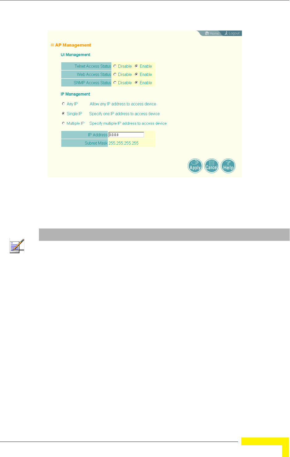
Advanced Configuration
BreezeMAX Wi² and BreezeACCESS Wi² System Manual 63
UI Management – Enables or disables management access through Telnet, the
Web (HTTP), or SNMP interfaces. (Default: Enabled)
IP Management – Restricts management access to Telnet, Web, and SNMP
interfaces to specified IP addresses. (Default: Any IP)
Any IP: Indicates that any IP address is allowed management access.
Single IP: Specifies a single IP address that is allowed management access.
Multiple IP: Specifies an address range as defined by the entered IP address
and subnet mask. For example, IP address 192.168.1.6 and subnet mask
255.255.255.0, defines all IP addresses from 192.168.1.6 to 192.168.1.254.
Figure 4-9: AP Management
NOTE
Secure Web (HTTPS) connections are not affected by the UI Management or IP Management
settings.
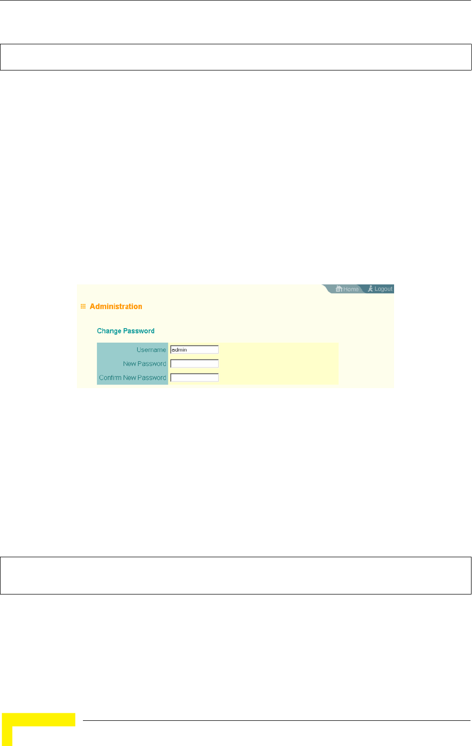
64 Operation
Chapter 4 - System Configuration
4.2.9.0.1 CLI Commands for AP Management features.
4.2.10 Administration
4.2.10.1 Changing the Password
Management access to the web and CLI interface on the AP is controlled through a
single user name and password. You can also gain additional access security by
using control filters (see “Filter Control” on page 57).
To protect access to the management interface, you need to change the default
user name and password as soon as possible. If the user name and password are
not changed, anyone having access to the AP can compromise AP and network
security. Once a new administrator has been configured, you can delete the
default admin user name from the system.
Username – The name of the user. The default name is admin. (Length: 3-16
characters, case sensitive)
New Password – The password for management access. (Length: 3-16 characters,
case sensitive)
Confirm New Password – Enter the password again for verification.
4.2.10.1.1 CLI Commands for Changing User Name and Password
Use the username and password commands from the CLI configuration mode.
4.2.10.2 Setting the Timeout Interval
You can set the timeout interval for web access to the unit, after which the user
will have to re-enter the username and password.
Enterprise AP(config)#apmgmtip multiple 192.168.1.6 255.255.255.0 147
Enterprise AP(config)#apmgmtui SNMP enable 148
Figure 4-10: Administration
Enterprise AP(config)#username bob 142
Enterprise AP(config)#password admin 143
Enterprise AP#
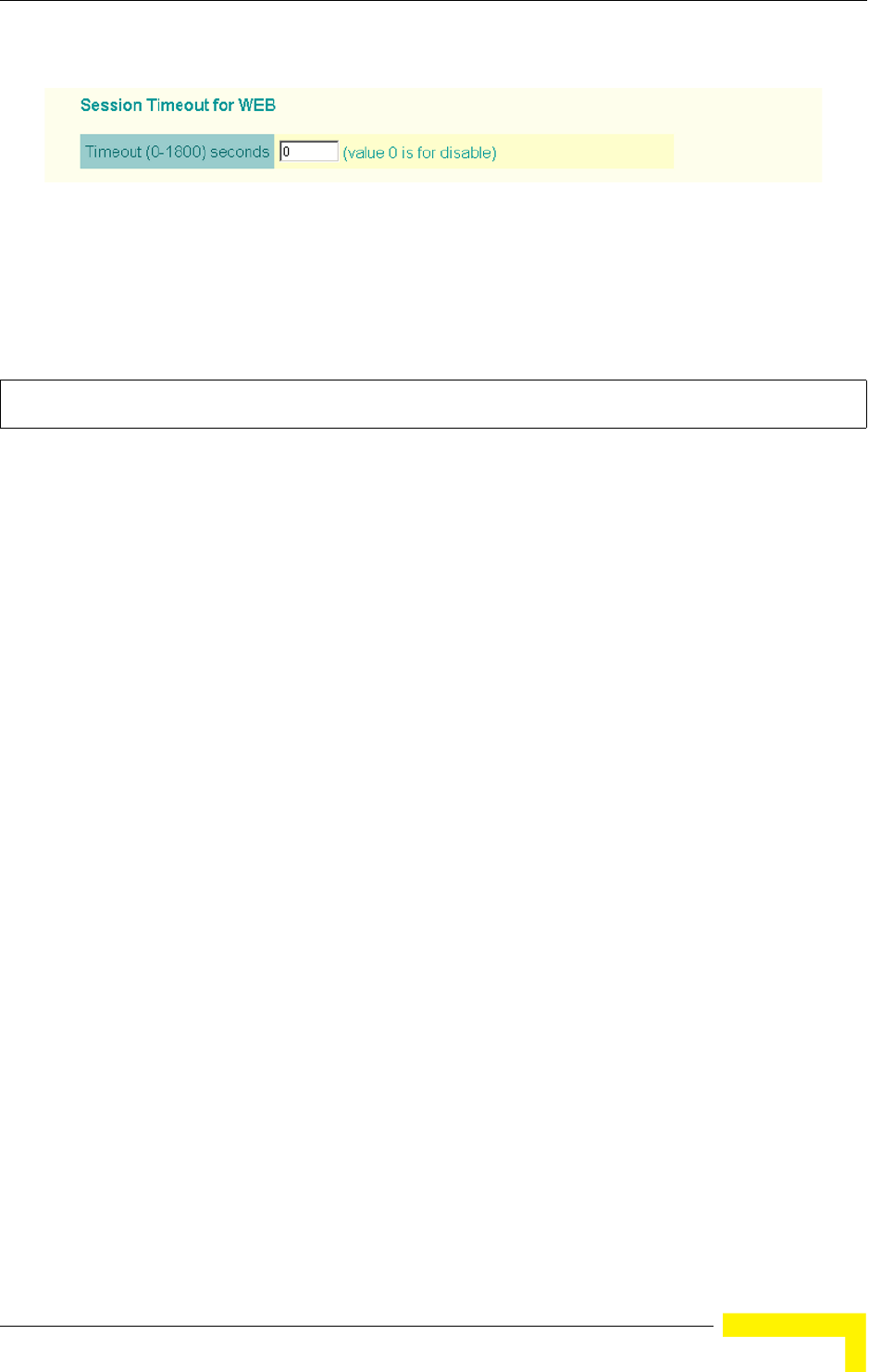
Advanced Configuration
BreezeMAX Wi² and BreezeACCESS Wi² System Manual 65
Session Timeout for WEB: Sets the time limit for an idle web interface session.
(Range: 0-1800 seconds; Default: 300 seconds; 0 is disabled)
4.2.10.2.1 CLI Command for the Web Session Timeout
Use the ip http session-timeout command from the CLI configuration mode.
4.2.10.3 Upgrading Firmware
You can upgrade new AP software from a local file on the management
workstation, or from an FTP or TFTP server. New software may be provided
periodically from your distributor.
After upgrading new software, you must reboot the AP to implement the new code.
Until a reboot occurs, the AP will continue to run the software it was using before
the upgrade started. Also note that new software that is incompatible with the
current configuration automatically restores the AP to the factory default settings
when first activated after a reboot.
Figure 4-11: Session Timeout for WEB
Enterprise AP(config)#ip http session-timeout 0 145
Enterprise AP(config)#
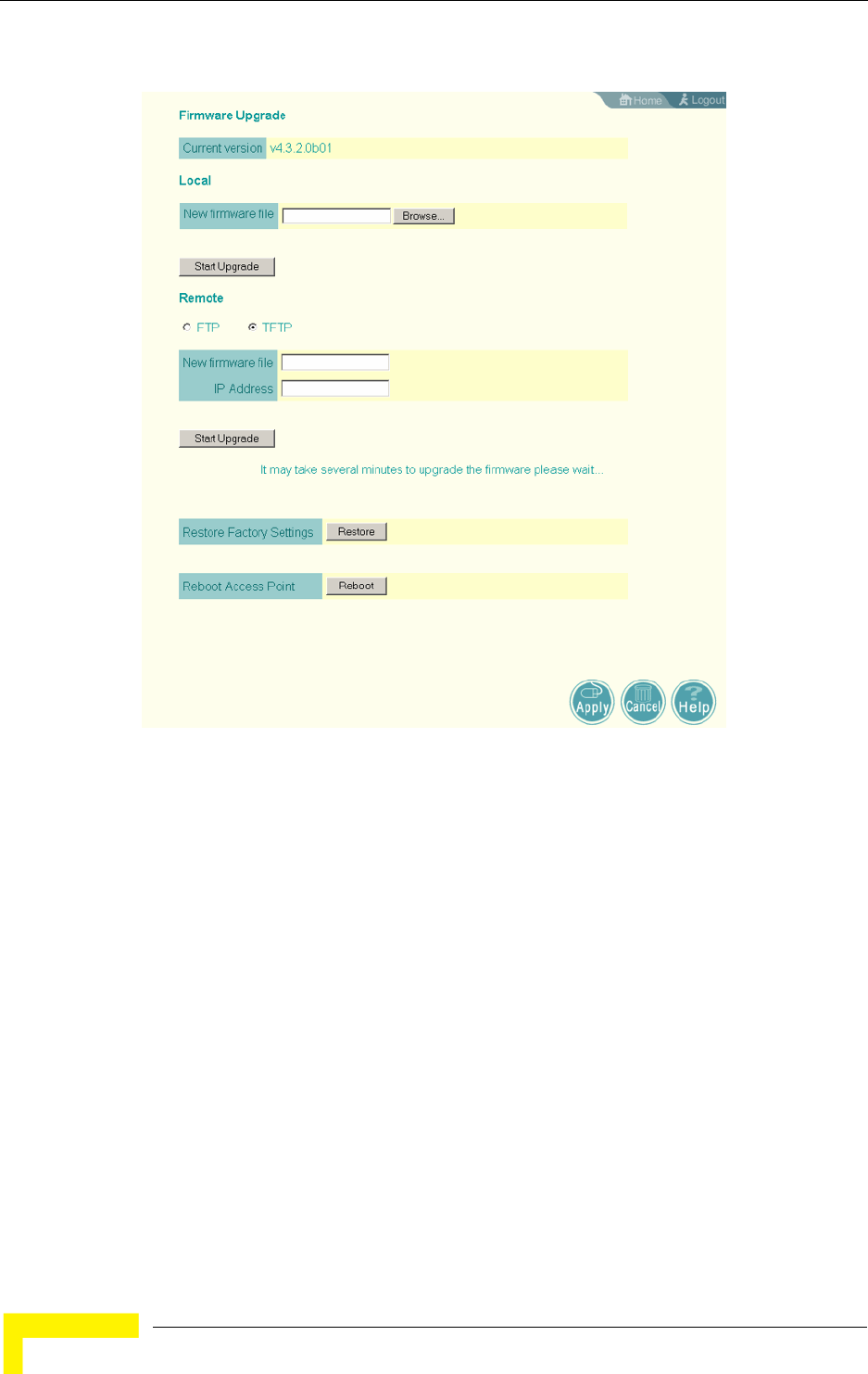
66 Operation
Chapter 4 - System Configuration
Before upgrading new software, verify that the AP is connected to the network and
has been configured with a compatible IP address and subnet mask.
If you need to download from an FTP or TFTP server, take the following additional
steps:
Obtain the IP address of the FTP or TFTP server where the AP software is
stored.
If upgrading from an FTP server, be sure that you have an account configured
on the server with a user name and password.
If VLANs are configured on the AP, determine the VLAN ID with which the FTP
or TFTP server is associated, and then configure the management station, or
the network port to which it is attached, with the same VLAN ID. If you are
Figure 4-12: Firmware Upgrade

Advanced Configuration
BreezeMAX Wi² and BreezeACCESS Wi² System Manual 67
managing the AP from a wireless client, the VLAN ID for the wireless client
must be configured on a RADIUS server.
Current version – Version number of runtime code.
Firmware Upgrade Local – Downloads an operation code image file from the web
management station to the AP using HTTP. Use the Browse button to locate the
image file locally on the management station and click Start Upgrade to proceed.
New firmware file: Specifies the name of the code file on the server. The new
firmware file name should not contain slashes (\ or /), the leading letter of the
file name should not be a period (.), and the maximum length for file names is
32 characters for files on the access point. (Valid characters: A-Z, a-z, 0-9, “.”,
“-”, “_”)
Firmware Upgrade Remote – Downloads an operation code image file from a
specified remote FTP or TFTP server. After filling in the following fields, click Start
Upgrade to proceed.
New firmware file: Specifies the name of the code file on the server.
The new
firmware file name should not contain slashes (\ or /),
the leading letter of the
file name should not be a period (.), and the maximum length for file names on
the FTP/TFTP server is 255 characters or 32 characters for files on the access
point. (Valid characters: A-Z, a-z, 0-9, “.”, “-”, “_”)
IP Address: IP address or host name of FTP or TFTP server.
Username: The user ID used for login on an FTP server.
Password: The password used for login on an FTP server.
Configuration File Backup/Restore – Uploads the current AP configuration file to a
specified remote FTP or TFTP server. A configuration file can also be downloaded
to the AP to restore a specific configuration.
Export/Import: Select Export to upload a file to an FTP/TFTP server. Select
Import to download a file from an FTP/TFTP server.
Config file: Specifies the name of the configuration file, which must always be
"syscfg." A path on the server can be specified using “/” in the name, providing
the path already exists; for example, “myfolder/syscfg.” Other than to indicate
a path, the file name must not contain any slashes (\ or /), the leading letter

68 Operation
Chapter 4 - System Configuration
cannot be a period (.), and the maximum length for file names on the
FTP/TFTP server is 255 characters. (Valid characters: A-Z, a-z, 0-9, “.”, “-”, “_”)
IP Address: IP address or host name of FTP or TFTP server.
Username: The user ID used for login on an FTP server.
Password: The password used for login on an FTP server.
Restore Factory Settings – Click the Restore button to reset the configuration
settings for the AP to the factory defaults and reboot the system. Note that all user
configured information will be lost. You will have to re-enter the default user name
(admin) to re-gain management access to this device.
Reboot Access Point – Click the Reset button to reboot the system.
Upon uploading a new configuration file you will be prompted to either restore
factory settings, or reboot the unit.
4.2.10.3.1 CLI Commands for Downloading Software from a TFTP Server
Use the copy tftp file command from the Exec mode and then specify the file
type, name, and IP address of the TFTP server. When the download is complete,
NOTE
If you have upgraded system software, then you must reboot the AP to implement the new
operation code. New software that is incompatible with the current configuration automatically
restores the AP to default values when first activated after a reboot.
Figure 4-13: New Configuration Warning

Advanced Configuration
BreezeMAX Wi² and BreezeACCESS Wi² System Manual 69
the dir command can be used to check that the new file is present in the AP file
system. To run the new software, use the reset board command to reboot the AP.
Enterprise AP#copy tftp file 181
1. Application image
2. Config file
3. Boot block image
Select the type of download<1,2,3>: [1]:1
TFTP Source file name:img.bin
TFTP Server IP:192.168.1.19
Enterprise AP#dir 183
File Name Type File Size
-------------------------- ---- -----------
dflt-img.bin 2 1319939
img.bin 2 1629577
syscfg 5 17776
syscfg_bak 5 17776
262144 byte(s) available
Enterprise AP#reset board 136
Reboot system now? <y/n>: y
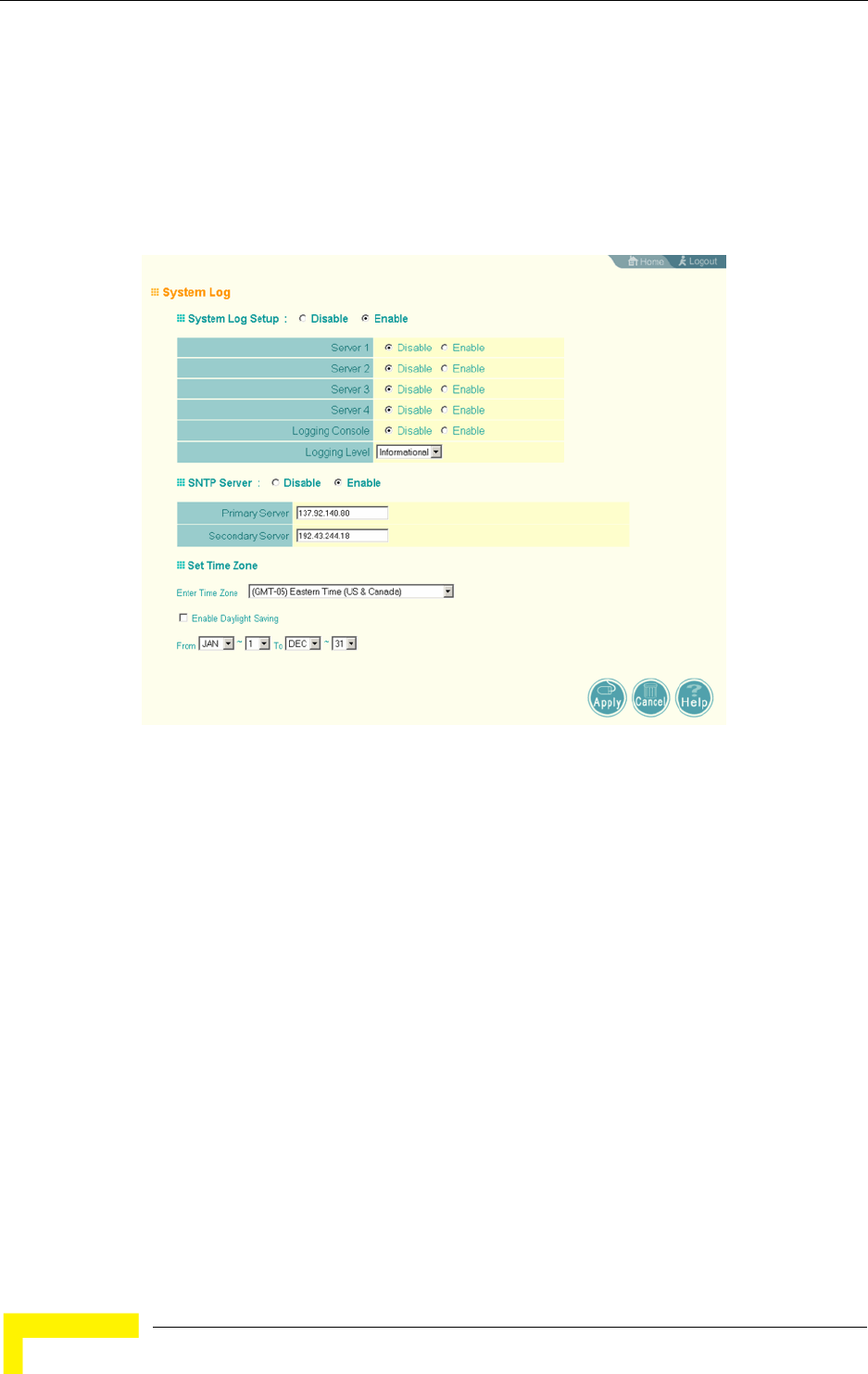
70 Operation
Chapter 4 - System Configuration
4.2.11 System Log
The AP can be configured to send event and error messages to a System Log
Server. The system clock can also be synchronized with a time server, so that all
the messages sent to the Syslog server are stamped with the correct time and
date.
4.2.11.1 Enabling System Logging
The AP supports a logging process that can control error messages saved to
memory or sent to a Syslog server. The logged messages serve as a valuable tool
for isolating AP and network problems.
System Log Setup – Enables the logging of error messages. (Default: Disable)
Server (1-4) – Enables the sending of log messages to a Syslog server host. Up to
four Syslog servers are supported on the AP. (Default: Disable)
Server Name/IP – The IP address or name of a Syslog server. (Default: 0.0.0.0)
UDP Port – The UDP port used by a Syslog server. (Range: 514 or 11024-65535;
Default: 514)
Logging Console – Enables the logging of error messages to the console.
(Default: Disable)
Figure 4-14: System Log
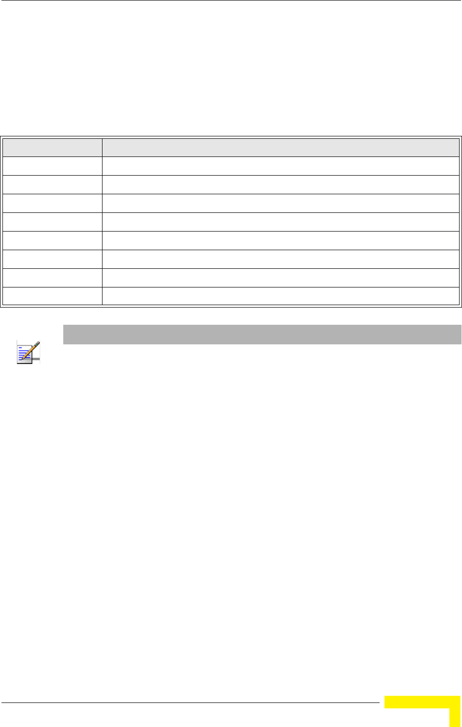
Advanced Configuration
BreezeMAX Wi² and BreezeACCESS Wi² System Manual 71
Logging Level – Sets the minimum severity level for event logging.
(Default: Informational)
The system allows you to limit the messages that are logged by specifying a
minimum severity level. Table 4-3 lists the error message levels from the most
severe (Emergency) to least severe (Debug). The message levels that are logged
include the specified minimum level up to the Emergency level.
Logging Facility Type – Sets the facility type for remote logging of syslog messages.
The command specifies the facility type tag sent in syslog messages. (See RFC
3164.) This type has no effect on the kind of messages reported by the switch.
However, it may be used by the syslog server to sort messages or to store
messages in the corresponding database. (Range: 16-23; Default: 16)
4.2.11.1.1 CLI Commands for System Logging
To enable logging on the AP, use the logging on command from the global
configuration mode. The logging level command sets the minimum level of
message to log. Use the logging console command to enable logging to the
console. Use the logging host command to specify up to four Syslog servers. The
CLI also allows the logging facility-type command to set the facility-type number
Table 4-3: Error Message Levels
Error Level Description
Emergency System unusable
Alerts Immediate action needed
Critical Critical conditions (e.g., memory allocation, or free memory error - resource exhausted)
Error Error conditions (e.g., invalid input, default used)
Warning Warning conditions (e.g., return false, unexpected return)
Notice Normal but significant condition, such as cold start
Informational Informational messages only
Debug Debugging messages
NOTE
The AP error log can be viewed using the Event Logs window in the Status section ( page 120).
The Event Logs window displays the last 128 messages logged in chronological order, from the
newest to the oldest. Log messages saved in the AP’s memory are erased when the device is
rebooted.

72 Operation
Chapter 4 - System Configuration
to use on the Syslog server. To view the current logging settings, use the show
logging command.
4.2.11.2 Configuring SNTP
Simple Network Time Protocol (SNTP) allows the AP to set its internal clock based
on periodic updates from a time server (SNTP or NTP). Maintaining an accurate
time on the AP enables the system log to record meaningful dates and times for
event entries. If the clock is not set, the AP will only record the time from the
factory default set at the last bootup.
The AP acts as an SNTP client, periodically sending time synchronization requests
to specific time servers. You can configure up to two time server IP addresses. The
AP will attempt to poll each server in the configured sequence.
SNTP Server – Configures the AP to operate as an SNTP client. When enabled, at
least one time server IP address must be specified.
Primary Server: The IP address of an SNTP or NTP time server that the AP
attempts to poll for a time update.
Secondary Server: The IP address of a secondary SNTP or NTP time server. The
AP first attempts to update the time from the primary server; if this fails it
attempts an update from the secondary server.
Enterprise AP(config)#logging on 157
Enterprise AP(config)#logging level alert 158
Enterprise AP(config)#logging console 158
Enterprise AP(config)#logging host 1 IP 10.1.0.3 514 157
Enterprise AP(config)#logging host 1 Port 514 157
Enterprise AP(config)#logging facility-type 19 159
Enterprise AP(config)#exit
Enterprise AP#show logging 160
Logging Information
============================================
Syslog State : Enabled
Logging Console State : Enabled
Logging Level : Alert
Logging Facility Type : 19
Servers
1: 10.1.0.3, UDP Port: 514, State: Enabled
2: 0.0.0.0, UDP Port: 514, State: Disabled
3: 0.0.0.0, UDP Port: 514, State: Disabled
4: 0.0.0.0, UDP Port: 514, State: Disabled
=============================================
Enterprise AP#

Advanced Configuration
BreezeMAX Wi² and BreezeACCESS Wi² System Manual 73
Set Time Zone – SNTP uses Coordinated Universal Time (or UTC, formerly
Greenwich Mean Time, or GMT) based on the time at the Earth’s prime meridian,
zero degrees longitude. To display a time corresponding to your local time, you
must indicate the number of hours your time zone is located before (east) or after
(west) UTC.
Enable Daylight Saving – The AP provides a way to automatically adjust the
system clock for Daylight Savings Time changes. To use this feature you must
define the month and date to begin and to end the change from standard time.
During this period the system clock is set back by one hour.
4.2.11.2.1 CLI Commands for SNTP
To enable SNTP support on the AP, from the global configuration mode specify
SNTP server IP addresses using the sntp-server ip command, then use the
sntp-server enable command to enable the service. Use the sntp-server
timezone command to set the time zone for your location, and the sntp-server
daylight-saving command to set daylight savings. To view the current SNTP
settings, use the show sntp command.
NOTE
The AP also allows you to disable SNTP and set the system clock manually.
Enterprise AP(config)#sntp-server ip 1 10.1.0.19 162
Enterprise AP(config)#sntp-server enable 163
Enterprise AP(config)#sntp-server timezone +8 164
Enterprise AP(config)#sntp-server daylight-saving 164
Enter Daylight saving from which month<1-12>: 3
and which day<1-31>: 31
Enter Daylight saving end to which month<1-12>: 10
and which day<1-31>: 31
Enterprise AP(config)#exit
Enterprise AP#show sntp 165
SNTP Information
=========================================================
Service State : Enabled
SNTP (server 1) IP : 10.1.0.19
SNTP (server 2) IP : 192.43.244.18
Current Time : 19 : 35, Oct 10th, 2003
Time Zone : +8 (TAIPEI, BEIJING)
Daylight Saving : Enabled, from Mar, 31st to Oct, 31st
=========================================================
Enterprise AP#

74 Operation
Chapter 4 - System Configuration
4.2.11.2.2 CLI Commands for the System Clock
The following example shows how to manually set the system time when SNTP
server support is disabled on the AP.
4.2.12 RSSI
RSSI is not applicable for the current release.
Enterprise AP(config)#no sntp-server enable 163
Enterprise AP(config)#sntp-server date-time 163
Enter Year<1970-2100>: 2003
Enter Month<1-12>: 10
Enter Day<1-31>: 10
Enter Hour<0-23>: 18
Enter Min<0-59>: 35
Enterprise AP(config)#
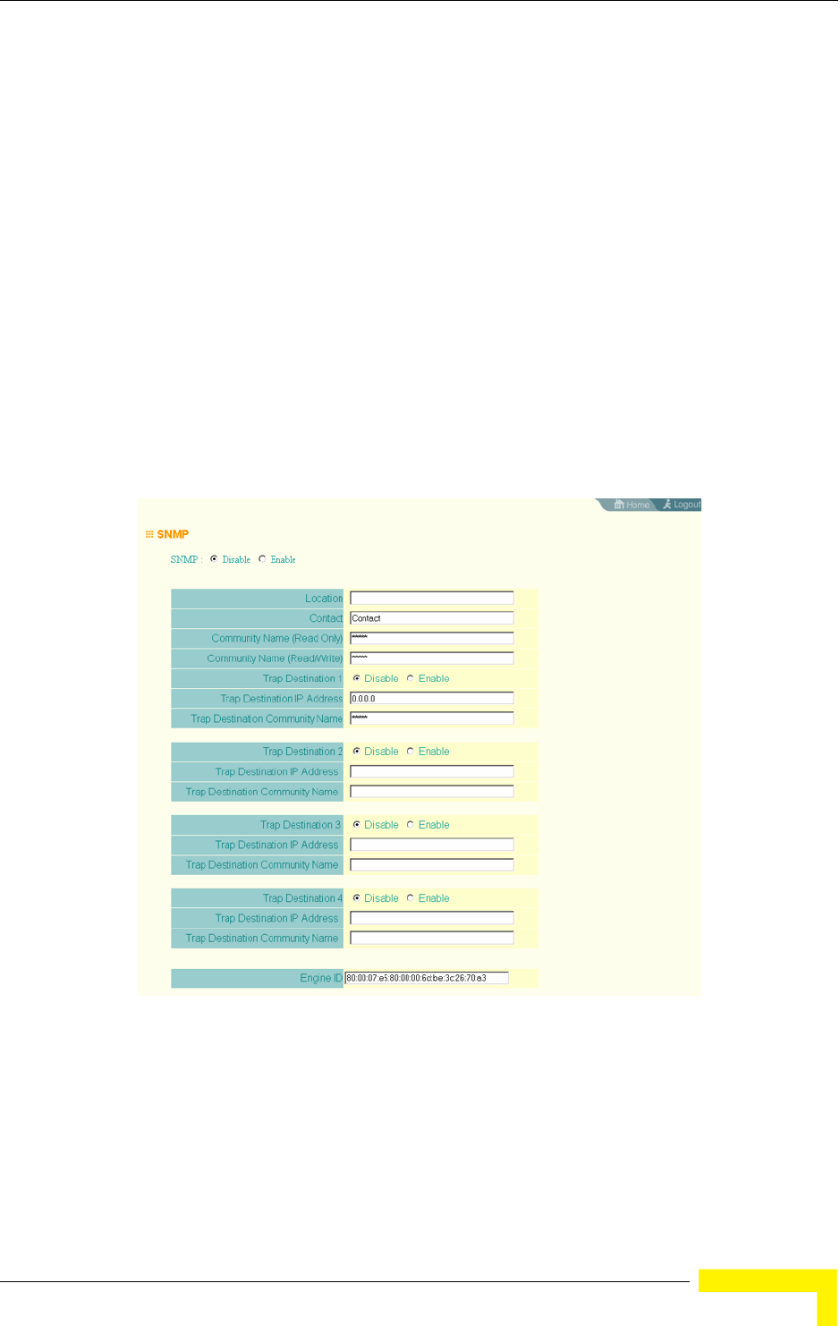
SNMP
BreezeMAX Wi² and BreezeACCESS Wi² System Manual 75
4.3 SNMP
You can use a network management application such as HP’s OpenView to
manage the AP via the Simple Network Management Protocol (SNMP) from a
network management station. To implement SNMP management, the AP must
have an IP address and subnet mask, configured either manually or dynamically.
Once an IP address has been configured, appropriate SNMP communities and
trap receivers should be configured.
Community names are used to control management access to SNMP stations, as
well as to authorize SNMP stations to receive trap messages from the AP. To
communicate with the AP, a management station must first submit a valid
community name for authentication. You therefore need to assign community
names to specified users or user groups and set the access level.
SNMP – Enables or disables SNMP management access and also enables the AP to
send SNMP traps (notifications). (Default: Disable)
Figure 4-15: SNMP

76 Operation
Chapter 4 - System Configuration
Location – A text string that describes the system location. (Maximum length: 255
characters)
Contact – A text string that describes the system contact. (Maximum length: 255
characters)
Community Name (Read Only) – Defines the SNMP community access string that
has read-only access. Authorized management stations are only able to retrieve
MIB objects. (Maximum length: 23 characters, case sensitive; Default: public)
Community Name (Read/Write) – Defines the SNMP community access string that
has read/write access. Authorized management stations are able to both retrieve
and modify MIB objects. (Maximum length: 23 characters, case sensitive;
Default: private)
Trap Destination (1 to 4) – Enables recipients (up to four) of SNMP notifications.
Trap Destination IP Address – Specifies the recipient of SNMP notifications.
Enter the IP address or the host name. (Host Name: 1 to 63 characters, case
sensitive)
Trap Destination Community Name – The community string sent with the
notification operation. (Maximum length: 23 characters, case sensitive;
Default: public)
Engine ID – Sets the engine identifier for the SNMPv3 agent that resides on the AP.
This engine protects against message replay, delay, and redirection. The engine ID
is also used in combination with user passwords to generate the security keys for
authenticating and encrypting SNMPv3 packets. A default engine ID is
automatically generated that is unique to the AP. (Range: 10 to 64 hexadecimal
characters)
NOTE
If the local engine ID is deleted or changed, all SNMP users will be cleared. All existing users will
need to be re-configured.
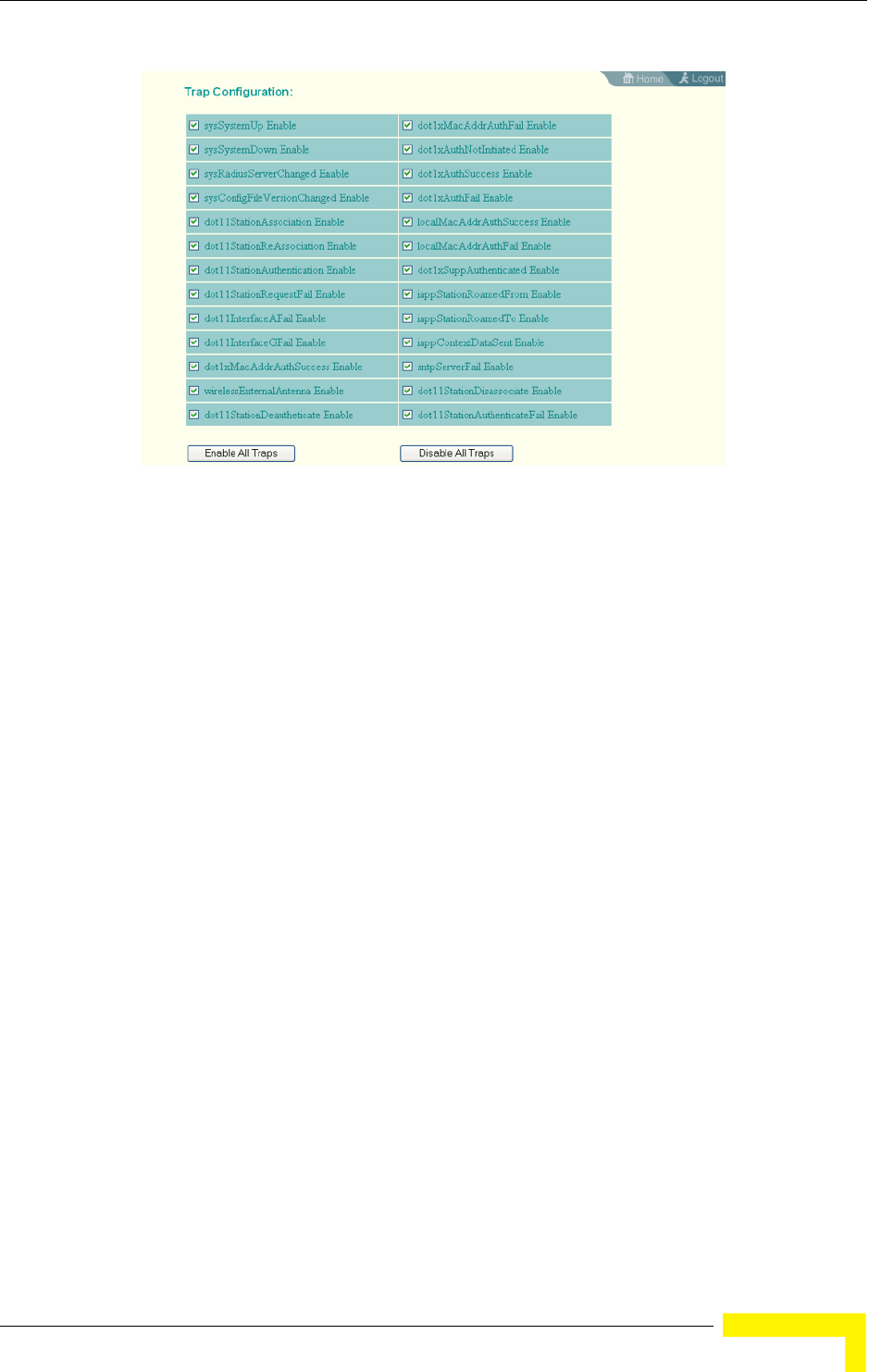
SNMP
BreezeMAX Wi² and BreezeACCESS Wi² System Manual 77
Trap Configuration – Allows selection of specific SNMP notifications to send. The
following items are available:
sysSystemUp - The AP is up and running.
sysSystemDown - The AP is about to shutdown and reboot.
sysRadiusServerChanged - The AP has changed from the primary RADIUS
server to the secondary, or from the secondary to the primary.
sysConfigFileVersionChanged - The AP’s configuration file has been changed.
dot11StationAssociation - A client station has successfully associated with the
AP.
dot11StationReAssociation - A client station has successfully re-associated
with the AP.
dot11StationAuthentication - A client station has been successfully
authenticated.
dot11StationRequestFail - A client station has failed association,
re-association, or authentication.
Figure 4-16: Trap Configuration

78 Operation
Chapter 4 - System Configuration
dot11InterfaceBFail - The 802.11b interface has failed.
dot1xMacAddrAuthSuccess - A client station has successfully authenticated its
MAC address with the RADIUS server.
dot1xMacAddrAuthFail - A client station has failed MAC address
authentication with the RADIUS server.
dot1xAuthNotInitiated - A client station did not initiate 802.1X authentication.
dot1xAuthSuccess - A 802.1X client station has been successfully
authenticated by the RADIUS server.
dot1xAuthFail - A 802.1X client station has failed RADIUS authentication.
dot1xSuppAuthenticated - A supplicant station has been successfully
authenticated by the RADIUS server
localMacAddrAuthSuccess - A client station has successfully authenticated its
MAC address with the local database on the AP.
localMacAddrAuthFail - A client station has failed authentication with the local
MAC address database on the AP.
iappStationRoamedFrom - A client station has roamed from another AP
(identified by its IP address).
iappStationRoamedTo - A client station has roamed to another AP (identified by
its IP address).
iappContextDataSent - A client station’s Context Data has been sent to another
AP with which the station has associated.
sntpServerFail - The AP has failed to set the time from the configured SNTP
server.
dot11WirelessStationDeauthenticate - A client station has de-authenticated
from the network.
dot11StationDisassociate - A client station no longer associates with the
network.

SNMP
BreezeMAX Wi² and BreezeACCESS Wi² System Manual 79
dot11StationAuthenticateFail - A client station has tried and failed to
authenticate to the network.
Enable All Traps - Click the button to enable all the available traps.
Disable All Traps - Click the button to disable all the available traps.
4.3.0.0.1 CLI Commands for SNMP and Trap Configuration
Use the snmp-server enable server command from the global configuration mode
to enable the SNMP agent. Use the snmp-server location and snmp-server
contact commands to indicate the physical location of the wi and define a system
contact. To set the read-only and read/write community names, use the
snmp-server community command. Use the snmp-server host command to
define a trap receiver host and the snmp-server trap command to enable or
disable specific traps.
Enterprise AP(config)#snmp-server enable server 170
Enterprise AP(config)#snmp-server community alpha rw 168
Enterprise AP(config)#snmp-server community beta ro
Enterprise AP(config)#snmp-server location WC-19 169
Enterprise AP(config)#snmp-server contact Paul 169
Enterprise AP(config)#snmp-server host 192.168.1.9 alpha 170
Enterprise AP(config)#snmp-server trap dot11StationAssociation 171
Enterprise AP(config)#

80 Operation
Chapter 4 - System Configuration
To view the current SNMP settings, use the show snmp command.
Enterprise AP#show snmp 179
SNMP Information
==============================================
Service State : Enable
Community (ro) : *****
Community (rw) : *****
Location : WC-19
Contact : Paul
EngineId :80:00:07:e5:80:00:00:2e:62:00:00:00:18
EngineBoots:1
Trap Destinations:
1: 192.168.1.9, Community: *****, State: Enabled
2: 0.0.0.0, Community: *****, State: Disabled
3: 0.0.0.0, Community: *****, State: Disabled
4: 0.0.0.0, Community: *****, State: Disabled
dot11InterfaceAGFail Enabled dot11InterfaceBFail Enabled
dot11StationAssociation Enabled dot11StationAuthentication Enabled
dot11StationReAssociation Enabled dot11StationRequestFail Enabled
dot1xAuthFail Enabled dot1xAuthNotInitiated Enabled
dot1xAuthSuccess Enabled dot1xMacAddrAuthFail Enabled
dot1xMacAddrAuthSuccess Enabled iappContextDataSent Enabled
iappStationRoamedFrom Enabled iappStationRoamedTo Enabled
localMacAddrAuthFail Enabled localMacAddrAuthSuccess Enabled
iappContextDataSent Enabled dot1XSuppAuthenticated Enabled
wirelessExternalAntenna Enabled dot11InterfaceAFail Enabled
dot11InterfaceGFail Enabled
pppLogonFail Enabled sntpServerFail Enabled
configFileVersionChanged Enabled radiusServerChanged Enabled
systemDown Enabled systemUp Enabled
=============================================
Enterprise AP#

Radio Interface
BreezeMAX Wi² and BreezeACCESS Wi² System Manual 81
4.4 Radio Interface
The 802.11g interface includes configuration options for radio signal
characteristics and wireless security features. The configuration options are
nearly identical, and are therefore both covered in this section of the manual.
The radio supports up to four virtual AP (VAP) interfaces numbered 0 to 3. Each
VAP functions as a separate AP, and can be configured with its own Service Set
Identification (SSID) and security settings. However, most radio signal parameters
apply to all four VAP interfaces.
The VAPs function similar to a VLAN, with each VAP mapped to its own VLAN ID.
Traffic to specific VAPs can be segregated based on user groups or application
traffic. Each VAP can have up to 64 wireless clients, whereby the clients associate
with these VAPs the same as they would with a physical AP.
4.4.1 Radio Settings G (802.11g)
The IEEE 802.11g standard operates within the 2.4 GHz band at up to 54 Mbps.
Also note that because the IEEE 802.11g standard is an extension of the IEEE
802.11b standard, it allows clients with 802.11b wireless network cards to
associate to an 802.11g access point.
First configure the radio settings that apply to the individual VAPs (Virtual Access
Point) and the common radio settings that apply to all of the 802.11g interfaces.
After you have configured the radio settings, go to the Security page under the
802.g Interface (see “Security” on page 4-98.), enable the radio service for any of
the VAP interfaces, and then set an SSID to identify the wireless network service
provided by each VAP. Remember that only clients with the same SSID can
associate with a VAP.
NOTE
802.11g is backward compatible with 802.11b. The 802.11g interface is configured independently
under the Radio Interface G: 802.11b/g web pages.
NOTE
The radio channel settings for the AP are limited by local regulations, which determine the number
of channels that are available. Refer to “Specifications” on page 4 for additional information on
the maximum number channels available.
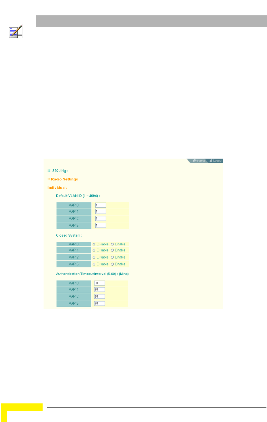
82 Operation
Chapter 4 - System Configuration
For information on configuring 802.11g settings, refer to the following sections:
“Configuring VAP Radio Settings” on page 82
“Configuring Rogue AP Detection” on page 84
“Configuring WiFi Multimedia” on page 92
4.4.1.1 Configuring VAP Radio Settings
To configure VAP radio settings, select the Radio Settings page.
NOTE
You must first enable VAP interface 0 before the other interfaces can be enabled.
Figure 4-17: Radio Settings Page
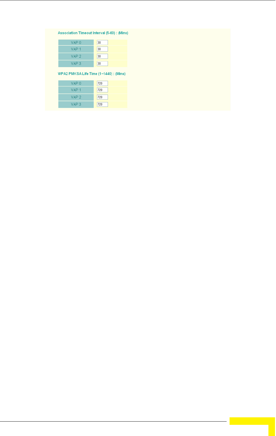
Radio Interface
BreezeMAX Wi² and BreezeACCESS Wi² System Manual 83
Default VLAN ID – The VLAN ID assigned to wireless clients associated to the VAP
interface that are not assigned to a specific VLAN by RADIUS server configuration.
(Default: 1)
Closed System – When enabled, the VAP interface does not include its SSID in
beacon messages. Nor does it respond to probe requests from clients that do not
include a fixed SSID. (Default: Disable)
Authentication Timeout Interval – The time within which the client should finish
authentication before authentication times out. (Range: 5-60 minutes; Default: 60
minutes)
Association Timeout Interval – The idle time interval (when no frames are sent)
after which a client is disassociated from the VAP interface. (Range: 5-60 minutes;
Default: 30 minutes)
WPA2 PMKSA Life Time – WPA2 provides fast roaming for authenticated clients by
retaining keys and other security settings in a cache for each VAP. In this way,
when clients roam back into a VAP they had previously been using,
re-authentication is not required. When a WPA2 client is first authenticated, it
receives a Pairwise Master Key (PMK) that is used to generate the other keys used
for unicast data encryption. This key and other client information form a client
Security Association (SA) that the VAP holds in a cache. When the lifetime expires,
the security association and keys are deleted from the cache. If the client returns
to an access point after the association has been deleted, it will require full
re-authentication. (Range: 1-1440 minutes; Default: 720 minutes)
4.4.1.1.1 CLI Commands for the Configuring the VAPs
From the global configuration mode, enter the interface wireless g command to
access the 802.11g radio interface. From the 802.11g interface mode, you can
access radio settings that apply to all VAP interfaces. To access a specific VAP
Figure 4-18: Radio Settings
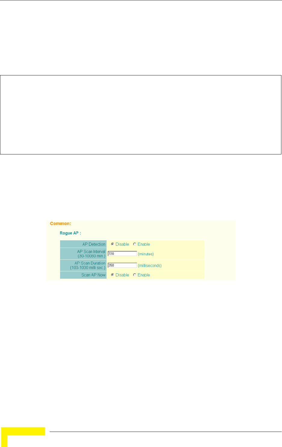
84 Operation
Chapter 4 - System Configuration
interface (numbered 0 to 3), use the vap command. You can configure a name for
each interface using the description command. You can also use the
closed-system command to stop sending the SSID in beacon messages. Set any
other VAP parameters and radio setting as required before enabling the VAP
interface (with the no shutdown command). To view the current 802.11g radio
settings for the VAP interface, use the show interface wireless g [0-3] command
as shown on page 210.
4.4.1.2 Configuring Rogue AP Detection
To configure Rouge AP detection, select the Radio Settings page, and scroll down
to the Rouge AP section.
Rogue AP – A “rogue AP” is either an AP that is not authorized to participate in the
wireless network, or an AP that does not have the correct security configuration.
Rogue APs can allow unauthorized access to the network, or fool client stations
into mistakenly associating with them and thereby blocking access to network
resources.
The AP can be configured to periodically scan all radio channels and find other
APs within range. A database of nearby APs is maintained where any rogue APs
can be identified. During a scan, Syslog messages (see “Enabling System Logging”
Enterprise AP(if-wireless g)#vap 0 210
Enterprise AP(if-wireless g: VAP[0])#description RD-AP#3 219
Enterprise AP(if-wireless g: VAP[0])#vlan-id 1 243
Enterprise AP(if-wireless g: VAP[0])#closed-system 220
Enterprise AP(if-wireless g: VAP[0])#authentication-timeout-
interval 30 221
Enterprise AP(if-wireless g: VAP[0])#association-timeout-
interval 20 221
Enterprise AP(if-wireless g: VAP[0])#max-association 32 220
Enterprise AP(if-wireless g: VAP[0])#pmksa-lifetime 900 236
Enterprise AP(if-wireless g: VAP[0])#
Figure 4-19: Rouge AP Section of Radio Settings page

Radio Interface
BreezeMAX Wi² and BreezeACCESS Wi² System Manual 85
on page 70) are sent for each AP detected. Rogue APs can be identified by
unknown BSSID (MAC address) or SSID configuration.
AP Detection – Enables the periodic scanning for other APs. (Default: Disable)
AP Scan Interval – Sets the time between each rogue AP scan. (Range: 30
-10080 minutes; Default: 720 minutes)
AP Scan Duration – Sets the length of time for each rogue AP scan. A long scan
duration time will detect more access points in the area, but causes more
disruption to client access. (Range: 100 -1000 milliseconds; Default: 350
milliseconds)
Rogue AP Authenticate – Enables or disables RADIUS authentication. Enabling
RADIUS Authentication allows the AP to discover rogue APs. With RADIUS
authentication enabled, the access point checks the MAC address/ Basic
Service Set Identifier (BSSID) of each access point that it finds against a
RADIUS server to determine whether the access point is allowed. With RADIUS
authentication disabled, the access point can detect its neighboring APs only;
it cannot identify whether the APs are allowed or are rogues. If you enable
RADIUS authentication, you must configure a RADIUS server for this AP (see
“RADIUS” on page 4-48.).
Scan AP Now – Starts an immediate rogue AP scan on the radio interface.
(Default: Disable)
4.4.1.2.1 CLI Commands for Rogue AP Detection
From the global configuration mode, enter the interface wireless command to
access the 802.11g radio interface. From the wireless interface mode, use the
rogue-ap enable command to enable rogue AP detection. Set the duration and
interval times with the rogue-ap duration and rogue-ap interval commands. If
required, start an immediate scan using the rogue-ap scan command. To view the
NOTE
While the AP scans a channel for rogue APs, wireless clients will not be able to connect to the
access point. Therefore, avoid frequent scanning or scans of a long duration unless there is a
reason to believe that more intensive scanning is required to find a rogue AP.

86 Operation
Chapter 4 - System Configuration
database of detected access points, use the show rogue-ap command from the
Exec level.
To configure the remaining 802.11g radio settings, select the Radio Settings
page.
Enterprise AP(config)#interface wireless g 210
Enter Wireless configuration commands, one per line.
Enterprise AP(if-wireless g)#rogue-ap enable 226
configure either syslog or trap or both to receive the rogue APs detected.
Enterprise AP(if-wireless g)#rogue-ap duration 200 227
Enterprise AP(if-wireless g)#rogue-ap interval 120 228
Enterprise AP(if-wireless g)#rogue-ap scan 228
Enterprise AP(if-wireless g)#rogueApDetect Completed (Radio G) : 5 APs detected
rogueAPDetect (Radio G): refreshing ap database now
Enterprise AP(if-wireless g)#exit
Enterprise AP#show rogue-ap 229
802.11g Channel : Rogue AP Status
AP Address(BSSID) SSID Channel(MHz) RSSI
=======================================================
00-04-e2-2a-37-23 WLAN1AP 11(2462 MHz) 17
00-04-e2-2a-37-3d ANY 7(2442 MHz) 42
00-04-e2-2a-37-49 WLAN1AP 9(2452 MHz) 42
00-90-d1-08-9d-a7 WLAN1AP 1(2412 MHz) 12
00-30-f1-fb-31-f4 WLAN 6(2437 MHz) 16
Enterprise AP#
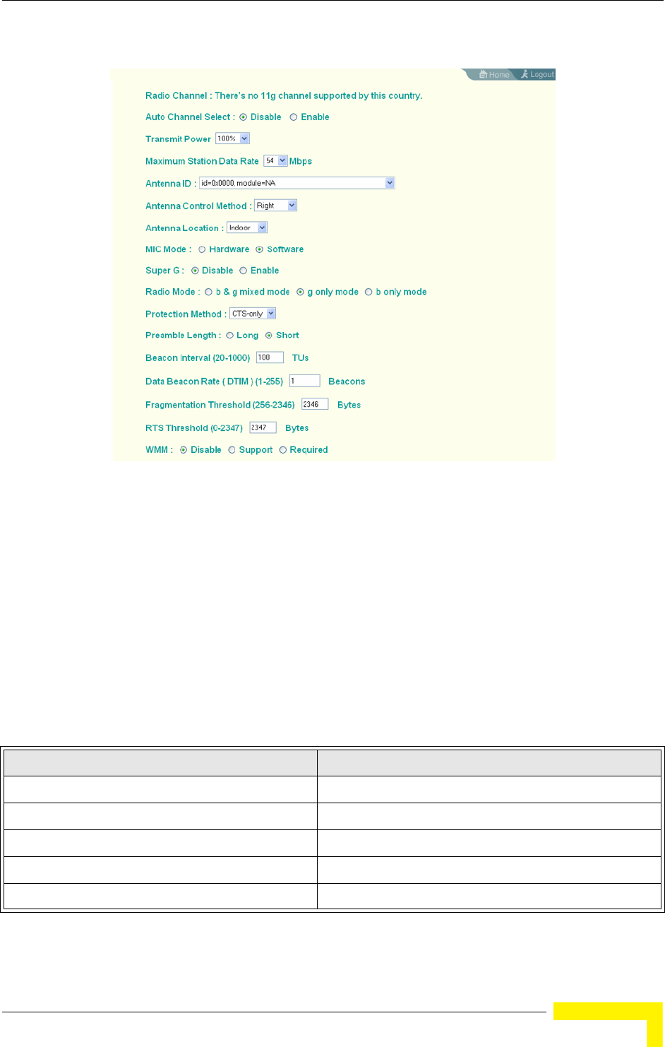
Radio Interface
BreezeMAX Wi² and BreezeACCESS Wi² System Manual 87
Radio Channel – The radio channel that the AP uses to communicate with wireless
clients. When multiple APs are deployed in the same area, set the channel on
neighboring access points at least four channels apart to avoid interference with
each other. This means that you can deploy up to three APs in the same area. (In
the United States you should use channels 1, 6 and 11. In most of Europe you
can also use channels 2, 7 and 12, or 3, 8 and 13).
Also note that the channel for wireless clients is automatically set to the same as
that used by the access point to which it is linked. In Turbo Mode (Super G
enabled) only channel 6 should be used. (Default: Channel 6))
Figure 4-20: Radio Setting Configuration
Table 4-4: Channels Assignment
Channel NumberV Frequency (GHz)
12.412
22.417
32.422
42.427
52.432
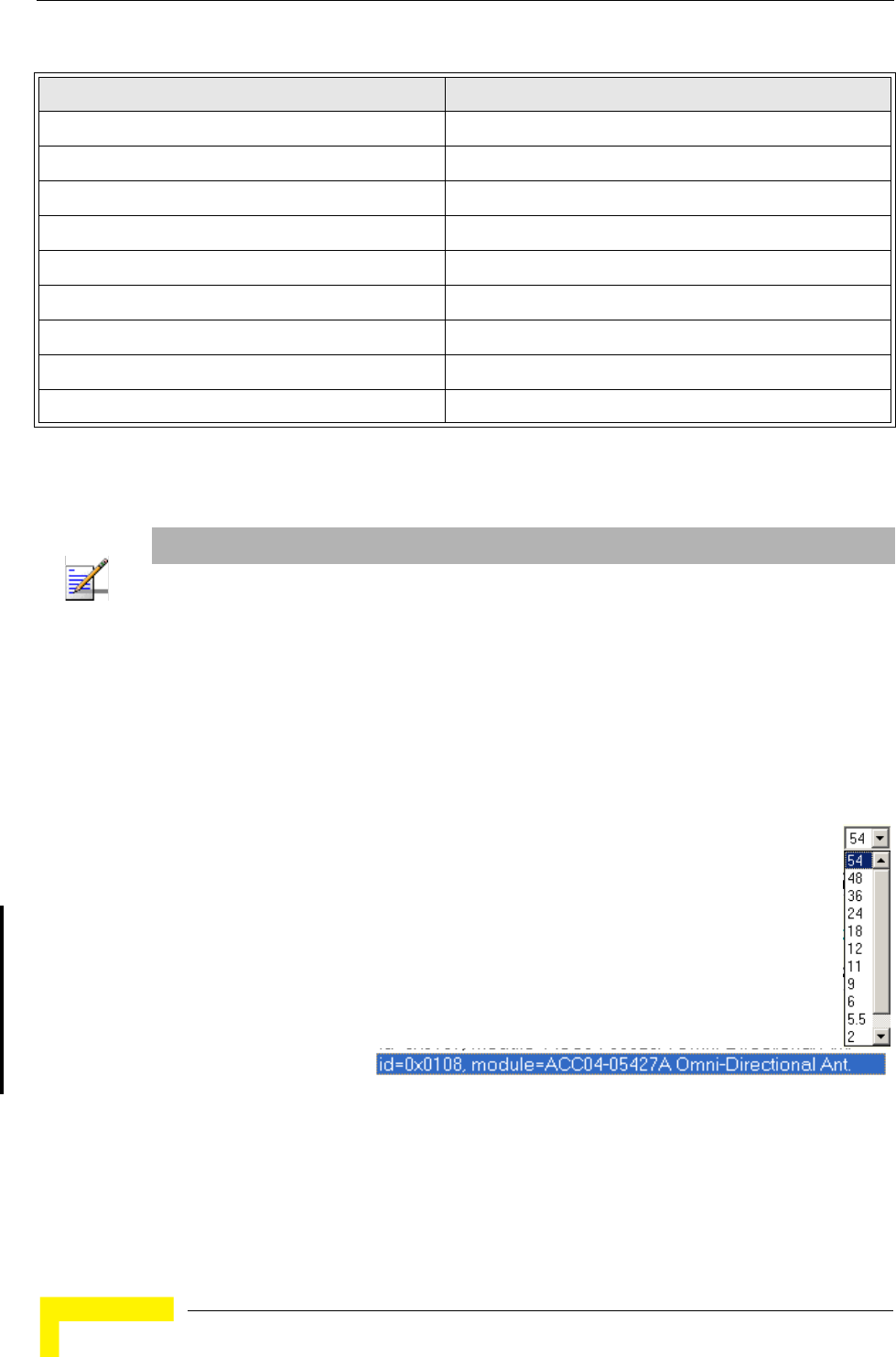
88 Operation
Chapter 4 - System Configuration
Auto Channel Select – Enables the AP to automatically select an unoccupied radio
channel. (Default: Enabled)
Transmit Power – Adjusts the power of the radio signals transmitted from the
access point. The higher the transmission power, the farther the transmission
range. Power selection is not just a trade off between coverage area and maximum
supported clients. You also have to ensure that high-power signals do not
interfere with the operation of other radio devices in the service area. (Options:
100%, 50%, 25%, 12%, minimum; Default: 100%)
Maximum Station Data Rate – The maximum data rate at which the access
point transmits unicast packets on the wireless interface. The maximum
transmission distance is affected by the data rate. The lower the data rate,
the longer the transmission distance. (Default: 54 Mbps)
Antenna ID – Selects
the antenna to be used
by the AP. The optional external antennas that are certified for use with the access
point are listed in the drop-down menu. Selecting the correct antenna ID ensures
that the AP's radio transmissions are within regulatory power limits for the
country of operation. In the current release, select id-0x0108,
62.437
72.442
82.447
92.452
10 2.457
11 2.462
12 2.467
13 2.472
14 2.482
NOTE
Check your country’s regulations to see if Auto Channel can be disabled.
Table 4-4: Channels Assignment
Channel NumberV Frequency (GHz)

Radio Interface
BreezeMAX Wi² and BreezeACCESS Wi² System Manual 89
module-ACC04-05427A Omni-Directional Ant from the list for the 8dBi omni
antenna(s). The unit will not transmit until an antenna is selected.
(Default:id=0x0000, module=NA)
Antenna Control Method - Selects the use of two antennas operating in diversity
mode or a single antenna. (Default: Diversity)
Diversity: The radio uses two identical antennas in a diversity system.
Right: The radio uses a single antenna on the right side.
Left: The radio uses a single antenna on the left side.
Antenna Location – Selects the mounting location of the antenna in use. Selecting
the correct location ensures that the access point only uses radio channels that
are permitted in the country of operation. (Default: Outdoor)
MIC Mode – The Michael Integrity Check (MIC) is part of the Temporal Key
Integrity Protocol (TKIP) encryption used in WiFi Protected Access (WPA) security.
The MIC calculation is performed in the access point for each transmitted packet
and this can impact throughput and performance. The AP supports a choice of
software or hardware MIC calculation. The performance of the AP can be improved
by selecting the best method for the specific deployment. (Default: Software)
Hardware: Provides best performance when the number of supported clients is
less than 27.
Software: Provides the best performance for a large number of clients on one
radio interface. Throughput may be reduced when the 802.11g interface
supports a high number of clients simultaneously.
Super G – The Atheros proprietary Super G performance enhancements are
supported by the access point. These enhancements include bursting,
compression, and fast frames. Maximum throughput ranges between 40 to 60
Mbps for connections to Atheros-compatible clients. (Default: Disabled)
Radio Mode – Selects the operating mode for the 802.11g wireless interface.
(Default: 802.11b+g)
NOTE
The Antenna ID must be selected in conjunction with the Antenna Control Method to configure
proper use of any of the antenna options.

90 Operation
Chapter 4 - System Configuration
802.11b+g: Both 802.11b and 802.11g clients can communicate with the
access point (up to 54 Mbps).
802.11b only: Both 802.11b and 802.11g clients can communicate with the
access point, but 802.11g clients can only transfer data at 802.11b standard
rates (up to 11 Mbps).
802.11g only: Only 802.11g clients can communicate with the access point (up
to 54 Mbps).
Auto Channel Select – Enables the access point to automatically select an
unoccupied radio channel. (Default: Enabled)
Preamble – Sets the length of the signal preamble that is used at the start of a
data transmission. (Default: Long)
Long: Sets the preamble to long (192 microseconds). Using a long preamble
ensures the access point can support all 802.11b and 802.11g clients.
Short or Long: Sets the preamble according to the capability of clients that are
currently associated. Uses a short preamble (96 microseconds) if all associated
clients can support it, otherwise a long preamble is used. The access point can
increase data throughput when using a short preamble, but will only use a
short preamble if it determines that all associated clients support it.
Beacon Interval – The rate at which beacon signals are transmitted from the
access point. The beacon signals allow wireless clients to maintain contact with
the access point. They may also carry power-management information.
(Range: 20-1000 TUs; Default: 100 TUs)
Data Beacon Rate – The rate at which stations in sleep mode must wake up to
receive broadcast/multicast transmissions.
Known also as the Delivery Traffic Indication Map (DTIM) interval, it indicates how
often the MAC layer forwards broadcast/multicast traffic, which is necessary to
wake up stations that are using Power Save mode. The default value of 2 indicates
that the access point will save all broadcast/multicast frames for the Basic
Service Set (BSS) and forward them after every second beacon. Using smaller
DTIM intervals delivers broadcast/multicast frames in a more timely manner,
causing stations in Power Save mode to wake up more often and drain power
faster. Using higher DTIM values reduces the power used by stations in Power
Save mode, but delays the transmission of broadcast/multicast frames.
(Range: 1-255 beacons; Default: 1 beacon)

Radio Interface
BreezeMAX Wi² and BreezeACCESS Wi² System Manual 91
Multicast Data Rate – The maximum data rate at which the access point
transmits multicast and broadcast packets on the wireless interface. (Options:
24, 12, 6 Mbps; Default: 6 Mbps)
Fragmentation Length – Configures the minimum packet size that can be
fragmented when passing through the access point. Fragmentation of the PDUs
(Package Data Unit) can increase the reliability of transmissions because it
increases the probability of a successful transmission due to smaller frame size. If
there is significant interference present, or collisions due to high network
utilization, try setting the fragment size to send smaller fragments. This will speed
up the retransmission of smaller frames. However, it is more efficient to set the
fragment size larger if very little or no interference is present because it requires
overhead to send multiple frames. (Range: 256-2346 bytes; Default: 2346 bytes)
RTS Threshold – Sets the packet size threshold at which a Request to Send (RTS)
signal must be sent to a receiving station prior to the sending station starting
communications. The access point sends RTS frames to a receiving station to
negotiate the sending of a data frame. After receiving an RTS frame, the station
sends a CTS (clear to send) frame to notify the sending station that it can start
sending data.
If the RTS threshold is set to 0, the access point always sends RTS signals. If set
to 2347, the access point never sends RTS signals. If set to any other value, and
the packet size equals or exceeds the RTS threshold, the RTS/CTS (Request to
Send / Clear to Send) mechanism will be enabled.
The APs contending for the medium may not be aware of each other. The
RTS/CTS mechanism can solve this “Hidden Node Problem.” (Range: 0-2347
bytes: Default: 2347 bytes)
4.4.1.2.2 CLI Commands for the 802.11g Wireless Interface
From the global configuration mode, enter the interface wireless g command to
access the 802.11g radio interface. The 802.11g radio can be forced to an
802.11g-only, 802.11b-only, or mixed 802.11b/g operating mode using the
radio-mode command. You should set the desired operating mode before
configuring channel settings (the default is mixed 802.11b/g operation). Select a
radio channel or set selection to Auto using the channel command. Set any
other radio settings as required before enabling the VAP interface (with the no
shutdown command). To view the current 802.11g radio settings for the VAP

92 Operation
Chapter 4 - System Configuration
interface, use the show interface wireless g [0~3] command as shown on
page 210.
4.4.1.2.3 CLI Commands for the Radio Settings
From the global configuration mode, enter the interface wireless g command to
access the 802.11g radio interface. From the 802.11g interface mode, you can
access radio settings that apply to all VAP interfaces. Use the turbo command to
enable this feature before setting the radio channel with the channel command.
Set any other radio setting as required before enabling the VAP interface (with the
no shutdown command). To view the current 802.11g radio settings for the VAP
interface, use the show interface wireless g [0~3] command as shown on
page 210.
4.4.1.3 Configuring WiFi Multimedia
Wireless networks offer an equal opportunity for all devices to transmit data from
any type of application. Although this is acceptable for most applications,
multimedia applications (with audio and video) are particularly sensitive to the
delay and throughput variations that result from this “equal opportunity” wireless
access method. For multimedia applications to run well over a wireless network, a
Enterprise AP(config)#interface wireless g 210
Enter Wireless configuration commands, one per line.
Enterprise AP(if-wireless g)#radio-mode g 214
Enterprise AP(if-wireless g)#channel auto 213
Enterprise AP(if-wireless g)#transmit-power full 213
Enterprise AP(if-wireless g)#super-g 218
Enterprise AP(if-wireless g)#preamble short 214
Enterprise AP(if-wireless g)#
Enterprise AP(config)#interface wireless g 210
Enter Wireless configuration commands, one per line.
Enterprise AP(if-wireless g)#channel 42 213
Enterprise AP(if-wireless g)#transmit-power full 213
Enterprise AP(if-wireless g)#speed 9 211
Enterprise AP(if-wireless g)#antenna id 0000 215
Enterprise AP(if-wireless g)#antenna control right 215
Enterprise AP(if-wireless g)#antenna location outdoor 216
Enterprise AP(if-wireless g)#mic_mode hardware 235
Enterprise AP(if-wireless g)#super-g 218
Enterprise AP(if-wireless g)#beacon-interval 150 216
Enterprise AP(if-wireless g)#beacon-interval 150
Enterprise AP(if-wireless g)#dtim-period 5 216
Enterprise AP(if-wireless g)#multicast-data-rate 6 211
Enterprise AP(if-wireless g)#fragmentation-length 512 217
Enterprise AP(if-wireless g)#rts-threshold 256 218
Enterprise AP(if-wireless g)#

Radio Interface
BreezeMAX Wi² and BreezeACCESS Wi² System Manual 93
Quality of Service (QoS) mechanism is required to prioritize traffic types and
provide an “enhanced opportunity” wireless access method.
The access point implements QoS using the WiFi Multimedia (WMM) standard.
Using WMM, the access point is able to prioritize traffic and optimize performance
when multiple applications compete for wireless network bandwidth at the same
time. WMM employs techniques that are a subset of the developing IEEE 802.11e
QoS standard and it enables the access point to inter operate with both WMM-
enabled clients and other devices that may lack any WMM functionality.
Access Categories — WMM defines four access categories (ACs): voice, video, best
effort, and background. These categories correspond to traffic priority levels and
are mapped to IEEE 802.1D priority tags (see Table 4-5). The direct mapping of
the four ACs to 802.1D priorities is specifically intended to facilitate inter
operability with other wired network QoS policies. While the four ACs are specified
for specific types of traffic, WMM allows the priority levels to be configured to
match any network-wide QoS policy. WMM also specifies a protocol that access
points can use to communicate the configured traffic priority levels to
QoS-enabled wireless clients.
WMM Operation — WMM uses traffic priority based on the four ACs; Voice,
Video, Best Effort, and Background. The higher the AC priority, the higher the
probability that data is transmitted.
When the access point forwards traffic, WMM adds data packets to four
independent transmit queues, one for each AC, depending on the 802.1D priority
tag of the packet. Data packets without a priority tag are always added to the Best
Effort AC queue. From the four queues, an internal “virtual” collision resolution
mechanism first selects data with the highest priority to be granted a transmit
Table 4-5: WMM Access Categories
Access
Category WMM
Designation Description 802.1D
Tags
AC_VO (AC3) Voice Highest priority, minimum delay. Time-sensitive data such as
VoIP (Voice over IP) calls.
7, 6
AC_VI (AC2) Video High priority, minimum delay. Time-sensitive data such as
streaming video.
5, 4
AC_BE (AC0) Best Effort Normal priority, medium delay and throughput. Data only
affected by long delays. Data from applications or devices that
lack QoS capabilities.
0, 3
AC_BK (AC1) Background Lowest priority. Data with no delay or throughput
requirements, such as bulk data transfers.
2, 1
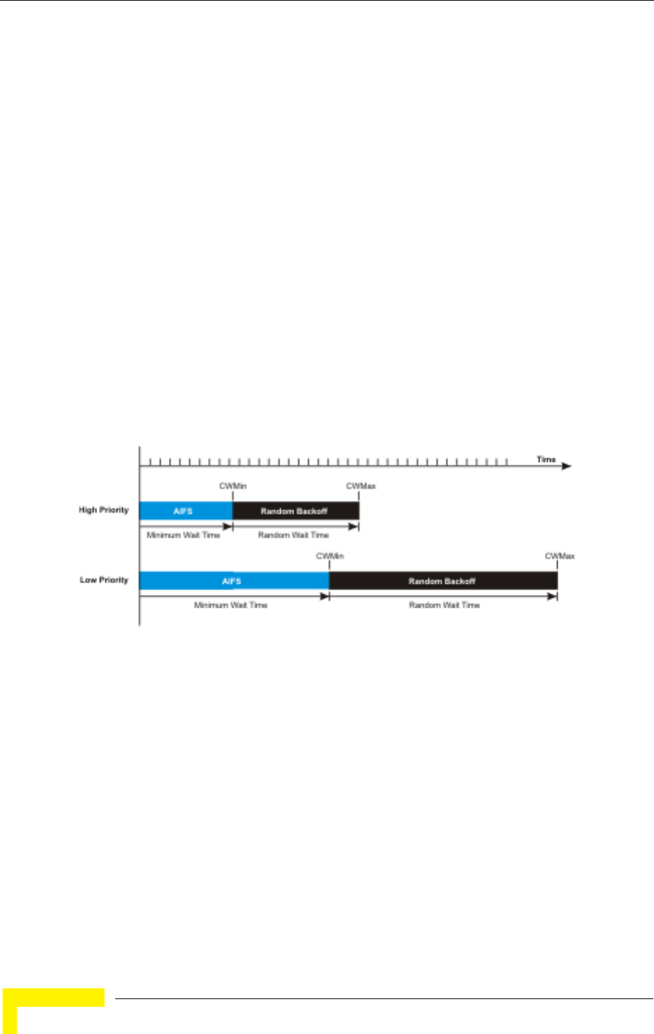
94 Operation
Chapter 4 - System Configuration
opportunity. Then the same collision resolution mechanism is used externally to
determine which device has access to the wireless medium.
For each AC queue, the collision resolution mechanism is dependent on two
timing parameters:
AIFSN (Arbitration Inter-Frame Space Number), a number used to calculate
the minimum time between data frames
CW (Contention Window), a number used to calculate a random backoff time
After a collision detection, a backoff wait time is calculated. The total wait time is
the sum of a minimum wait time (Arbitration Inter-Frame Space, or AIFS)
determined from the AIFSN, and a random backoff time calculated from a value
selected from zero to the CW. The CW value varies within a configurable range. It
starts at CWMin and doubles after every collision up to a maximum value,
CWMax. After a successful transmission, the CW value is reset to its CWMin
value.
For high-priority traffic, the AIFSN and CW values are smaller. The smaller values
equate to less backoff and wait time, and therefore more transmit opportunities.
To configure WMM, select the Radio Settings page, and scroll down to the WMM
configuration settings.
Figure 4-21: WMM Backoff Wait Times
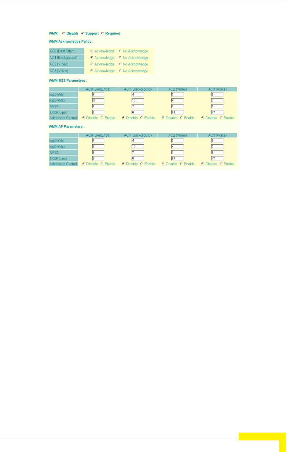
Radio Interface
BreezeMAX Wi² and BreezeACCESS Wi² System Manual 95
WMM – Sets the WMM operational mode on the AP. When enabled, the
parameters for each AC queue will be employed on the access point and QoS
capabilities are advertised to WMM-enabled clients. (Default: Support)
Disable: WMM is disabled.
Support: WMM will be used for any associated device that supports this
feature. Devices that do not support this feature may still associate with the
access point.
Required: WMM must be supported on any device trying to associated with the
access point. Devices that do not support this feature will not be allowed to
associate with the access point.
WMM Acknowledge Policy – By default, all wireless data transmissions require
the sender to wait for an acknowledgement from the receiver. WMM allows the
acknowledgement wait time to be turned off for each Access Category (AC).
Although this increases data throughput, it can also result in a high number of
errors when traffic levels are heavy. (Default: Acknowledge)
WMM BSS Parameters – These parameters apply to the wireless clients.
Figure 4-22: WMM Configuration Settings

96 Operation
Chapter 4 - System Configuration
WMM AP Parameters – These parameters apply to the access point.
logCWMin (Minimum Contention Window) – The initial upper limit of the
random backoff wait time before wireless medium access can be attempted.
The initial wait time is a random value between zero and the CWMin value.
Specify the CWMin value in the range 0-15 microseconds. Note that the
CWMin value must be equal or less than the CWMax value.
logCWMax (Maximum Contention Window) – The maximum upper limit of the
random backoff wait time before wireless medium access can be attempted.
The contention window is doubled after each detected collision up to the
CWMax value. Specify the CWMax value in the range 0-15 microseconds. Note
that the CWMax value must be greater or equal to the CWMin value.
AIFS (Arbitration Inter-Frame Space) – The minimum amount of wait time
before the next data transmission attempt. Specify the AIFS value in the range
0-15 microseconds.
TXOP Limit (Transmit Opportunity Limit) – The maximum time an AC
transmit queue has access to the wireless medium. When an AC queue is
granted a transmit opportunity, it can transmit data for a time up to the
TxOpLimit. This data bursting greatly improves the efficiency for high
data-rate traffic. Specify a value in the range 0-65535 microseconds.
Admission Control – The admission control mode for the access category.
When enabled, clients are blocked from using the access category. (Default:
Disabled)
Key Type – See “Wired Equivalent Privacy (WEP)” on page 104.
4.4.1.3.1 CLI Commands for WMM
Enter interface wireless mode and type wmm required for clients that want to
associate with the access point. The wmm-acknowledge-policy command is used
to enable or disable a policy for each access category. The wmmparms command
defines detailed WMM parameters.
Enterprise AP(if-wireless g)#wmm required 245
Enterprise AP(if-wireless g)#wmm-acknowledge-policy 0 noack 245
Enterprise AP(if-wireless g)#wmmparams ap 0 4 6 3 1 1 246

Radio Interface
BreezeMAX Wi² and BreezeACCESS Wi² System Manual 97
To view the current 802.11g radio settings for the VAP interface, use the show
interface wireless g [0-3] command.
Enterprise AP#show interface wireless g 0 222
Wireless Interface Information
=============================================================
--------------------Identification---------------------------
Description : Enterprise 802.11g Access Point
SSID : VAP_TEST_11G 0
Turbo Mode : DISABLED
Channel : 36 (AUTO)
Status : DISABLED
MAC Address : 00:12:cf:05:95:0c
----------------802.11 Parameters---------------------------
Transmit Power : FULL (16 dBm)
Max Station Data Rate : 54Mbps
Multicast Data Rate : 6Mbps
Fragmentation Threshold : 2346 bytes
RTS Threshold : 2347 bytes
Beacon Interval : 100 TUs
Authentication Timeout Interval : 60 Mins
Association Timeout Interval : 30 Mins
DTIM Interval : 1 beacon
Maximum Association : 64 stations
MIC Mode : Software
Super G : Disabled
VLAN ID : 1
----------------Security-------------------------------------
Closed System : Disabled
Multicast cipher : WEP
WPA clients : TKIP and AES
WPA Key Mgmt Mode : PRE SHARED KEY
WPA PSK Key Type : PASSPHRASE
Encryption : DISABLED
Default Transmit Key : 1
Common Static Keys : Key 1: EMPTY Key 2: EMPTY
Key 3: EMPTY Key 4: EMPTY
Authentication Type : OPEN
----------------802.1x---------------------------------------
802.1x :
Broadcast Key Refresh Rate : 30 min
Session Key Refresh Rate : 30 min
802.1x Session Timeout Value : 0 min
----------------Antenna--------------------------------------
Antenna Control method : Diversity
Antenna ID : 0x0000(Default Antenna)
Antenna Location : Outdoor

98 Operation
Chapter 4 - System Configuration
4.4.2 Security
The access point is configured by default as an “open system,” which broadcasts a
beacon signal including the configured SSID. Wireless clients with an SSID setting
of “any” can read the SSID from the beacon and automatically set their SSID to
allow immediate connection to the nearest access point.
To improve wireless network security, you have to implement two main functions:
Authentication: It must be verified that clients attempting to connect to the
network are authorized users.
Traffic Encryption: Data passing between the access point and clients must be
protected from interception and eavesdropping.
----------------Quality of Service---------------------------
WMM Mode : SUPPORTED
WMM Acknowledge Policy
AC0(Best Effort) : Ack
AC1(Background) : Acknowledge
AC2(Video) : Acknowledge
AC3(Voice) : Acknowledge
WMM BSS Parameters
AC0(Best Effort) : logCwMin: 4 logCwMax: 10 AIFSN: 3
Admission Control: No
TXOP Limit: 0.000 ms
AC1(Background) : logCwMin: 4 logCwMax: 10 AIFSN: 7
Admission Control: No
TXOP Limit: 0.000 ms
AC2(Video) : logCwMin: 3 logCwMax: 4 AIFSN: 2
Admission Control: No
TXOP Limit: 3.008 ms
AC3(Voice) : logCwMin: 2 logCwMax: 3 AIFSN: 2
Admission Control: No
TXOP Limit: 1.504 ms
WMM AP Parameters
AC0(Best Effort) : logCwMin: 4 logCwMax: 6 AIFSN: 3
Admission Control: No
TXOP Limit: 0.000 ms
AC1(Background) : logCwMin: 4 logCwMax: 10 AIFSN: 7
Admission Control: No
TXOP Limit: 0.000 ms
AC2(Video) : logCwMin: 3 logCwMax: 4 AIFSN: 1
Admission Control: No
TXOP Limit: 3.008 ms
AC3(Voice) : logCwMin: 2 logCwMax: 3 AIFSN: 1
Admission Control: No
TXOP Limit: 1.504 ms
=============================================================
Enterprise AP#

Radio Interface
BreezeMAX Wi² and BreezeACCESS Wi² System Manual 99
For a more secure network, the AP can implement one or a combination of the
following security mechanisms:
Wired Equivalent Privacy (WEP) page 99
IEEE 802.1X page 114
Wireless MAC address filtering page 54
WiFi Protected Access (WPA or WPA2) page 108
Both WEP and WPA security settings are configurable separately for each virtual
access point (VAP) interface. MAC address filtering, and RADIUS server settings
are global and apply to all VAP interfaces.
The security mechanisms that may be employed depend on the level of security
required, the network and management resources available, and the software
support provided on wireless clients.
A summary of wireless security considerations is listed in Table 4-6.
Table 4-6: Wireless Security Considerations
Security
Mechanism Client Support Implementation Considerations
WEP Built-in support on all 802.11g
devices
Provides only weak security
Requires manual key management
WEP over 802.1X Requires 802.1X client support in
system or by add-in software
(support provided in Windows
2000 SP3 or later and Windows
XP)
Provides dynamic key rotation for improved WEP
security
Requires configured RADIUS server
802.1X EAP type may require management of digital
certificates for clients and server
MAC Address
Filtering
Uses the MAC address of client
network card
Provides only weak user authentication
Management of authorized MAC addresses
Can be combined with other methods for improved
security
Optionally configured RADIUS server

100 Operation
Chapter 4 - System Configuration
The AP can simultaneously support clients using various different security
mechanisms. The configuration for these security combinations are outlined in
the following table. Note that MAC address authentication can be configured
WPA over 802.1X
Mode
Requires WPA-enabled system
and network card driver
(native support provided in
Windows XP)
Provides robust security in WPA-only mode
(i.e., WPA clients only)
Offers support for legacy WEP clients, but with
increased security risk (i.e., WEP authentication
keys disabled)
Requires configured RADIUS server
802.1X EAP type may require management of digital
certificates for clients and server
WPA PSK Mode Requires WPA-enabled system
and network card driver
(native support provided in
Windows XP)
Provides good security in small networks
Requires manual management of pre-shared key
WPA2 with 802.1X Requires WPA-enabled system
and network card driver (native
support provided in Windows XP)
Provides the strongest security in WPA2-only mode
Provides robust security in mixed mode for WPA and
WPA2 clients
Offers fast roaming for time-sensitive client
applications
Requires configured RADIUS server
802.1X EAP type may require management of digital
certificates for clients and server
Clients may require hardware upgrade to be WPA2
compliant
WPA2 PSK Mode Requires WPA-enabled system
and network card driver (native
support provided in Windows XP)
Provides robust security in small networks
Requires manual management of pre-shared key
Clients may require hardware upgrade to be WPA2
compliant
NOTE
You must enable data encryption through the web or CLI in order to enable all types of encryption
(WEP, TKIP, or AES) in the access point.
Table 4-6: Wireless Security Considerations
Security
Mechanism Client Support Implementation Considerations

Radio Interface
BreezeMAX Wi² and BreezeACCESS Wi² System Manual 101
independently to work with all security mechanisms and is indicated separately in
the table. Required RADIUS server support is also listed.
Table 4-7: Security Combinations
Client Security
Combination Configuration SummaryaMAC
AuthenticationbRADIUS
Server
No encryption and no
authentication
Interface Detail Settings:
Authentication: Open System
Encryption: Disable
802.1x: Disable
Local, RADIUS, or
Disabled
Yes3
Static WEP only (with
or without shared key
authentication)
Enter 1 to 4 WEP keys
Select a WEP transmit key for the interface
Interface Detail Settings:
Authentication: Shared Key or Open System
Encryption: Enable
802.1x: Disable
Local, RADIUS, or
Disabled
Yesc
Dynamic WEP
(802.1x) only
Interface Detail Settings:
Authentication: Open System
Encryption: Enable
802.1x: Required
Set 802.1x key refresh and reauthentication rates
Local, RADIUS, or
Disabled
Yesd
802.1x WPA only Interface Detail Settings:
Authentication: WPA
Encryption: Enable
WPA Configuration: Required
Cipher Suite: TKIP
802.1x: Required
Set 802.1x key refresh and reauthentication rates
Local only Yes
WPA Pre-Shared Key
only
Interface Detail Settings:
Authentication: WPA-PSK
Encryption: Enable
WPA Configuration: Required
Cipher Configuration: TKIP
802.1x: Disable
WPA Pre-shared Key Type: Hexadicmal or
Alphanumeric
Enter a WPA Pre-shared key
Local only No

102 Operation
Chapter 4 - System Configuration
Static and dynamic
(802.1x) WEP keys
Enter 1 to 4 WEP keys
Select a WEP transmit key
Interface Detail Settings:
Authentication: Open System
Encryption: Enable
802.1x: Supported
Set 802.1x key refresh and reauthentication rates
Local, RADIUS, or
Disabled
Yes
Dynamic WEP and
802.1x WPA
Interface Detail Settings:
Authentication: WPA
Encryption: Enable
WPA Configuration: Supported
Cipher Suite: WEP
802.1x: Required
Set 802.1x key refresh and reauthentication rates
Local or Disabled Yes
Static and dynamic
(802.1x) WEP keys
and 802.1x WPA
Enter 1 to 4 WEP keys
Select a WEP transmit key
Interface Detail Settings:
Authentication: WPA
Encryption: Enable
WPA Configuration: Supported
Cipher Suite: WEP
802.1x: Supported
Set 802.1x key refresh and reauthentication rates
Local or Disabled Yes
802.1x WPA2 only Interface Detail Settings:
Authentication: WPA2
Encryption: Enable
WPA Configuration: Required
Cipher Suite: AES-CCMP
802.1x: Required
Set 802.1x key refresh and reauthentication rates
Local or Disabled Yes
Table 4-7: Security Combinations
Client Security
Combination Configuration SummaryaMAC
AuthenticationbRADIUS
Server

Radio Interface
BreezeMAX Wi² and BreezeACCESS Wi² System Manual 103
4.4.2.1 Enabling the VAPs
Before enabling the Virtual Access Point (VAP) radio interfaces, first configure all
of the relevant radio settings (see “Radio Settings G (802.11g)” on page 81.)
WPA2 Pre-Shared Key
only
Interface Detail Settings:
Authentication: WPA2-PSK
Encryption: Enable
WPA Configuraton: Required
Cipher Suite: AES-CCMP
802.1x: Disable
WPA Pre-shared Key Type: Hexadicmal or
Alphanumeric
Enter a WPA Pre-shared key
Local or Disabled No
802.1x WPA-WPA2
Mixed Mode
Interface Detail Settings:
Authentication: WPA-WPA2-mixed
Encryption: Enable
WPA Configuration: Required
Cipher Suite: TKIP
802.1x: Required
Set 802.1x key refresh and reauthentication rates
Local or Disabled Yes
WPA-WPA2 Mixed
Mode Pre-Shared Key
Interface Detail Settings:
Authentication: WPA-WPA2-PSK-mixed
Encryption: Enable
WPA Configuration: Required
Cipher Suite: TKIP
802.1x: Disable
WPA Pre-shared Key Type: Hexadicmal or
Alphanumeric
Enter a WPA Pre-shared key
Local or Disabled No
a. The configuration summary does not include the set up for MAC authentication or RADIUS server .
b. The configuration of RADIUS MAC authentication together with 802.1x WPA or WPA Pre-shared Key
is not supported.
c. RADIUS server required only when RADIUS MAC authentication is configured.
d. RADIUS server required only when RADIUS MAC authentication is configured.
NOTE
If you choose to configure RADIUS MAC authentication together with 802.1X, the RADIUS MAC
address authentication occurs prior to 802.1X authentication. Only when RADIUS MAC
authentication succeeds is 802.1X authentication performed. When RADIUS MAC authentication
fails, 802.1X authentication is not performed.
Table 4-7: Security Combinations
Client Security
Combination Configuration SummaryaMAC
AuthenticationbRADIUS
Server
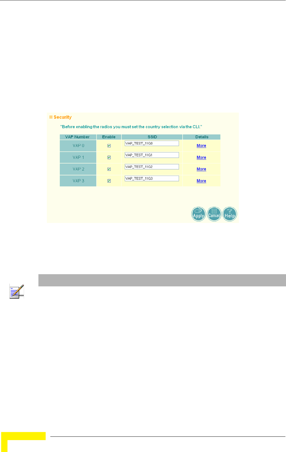
104 Operation
Chapter 4 - System Configuration
After you have configured the radio settings, select Security under Radio G, set an
SSID to identify the wireless network service provided by each VAP you want to
use, and then click Apply to save your settings.
Before enabling the radio service for any VAP, first configure the WEP, WPA, and
802.1X security settings described in the following sections. After you have
finished configuring the security settings, return to the main Security page shown
below, start the required VAP interfaces by clicking the Enable checkbox, and
then click Apply.
Enable – Enables radio communications on the VAP interface. (Default: Disabled)
SSID – The name of the basic service set provided by a VAP interface. Clients that
want to connect to the network through the access point must set their SSID to
the same as that of an access point VAP interface. (Default: VAP_TEST_11A #
(0-3); Range: 1-32 characters)
4.4.2.2 Wired Equivalent Privacy (WEP)
WEP provides a basic level of security, preventing unauthorized access to the
network, and encrypting data transmitted between wireless clients and the access
Figure 4-23: Security
NOTE
You must first enable VAP interface 0 before you can enable other VAP interfaces.
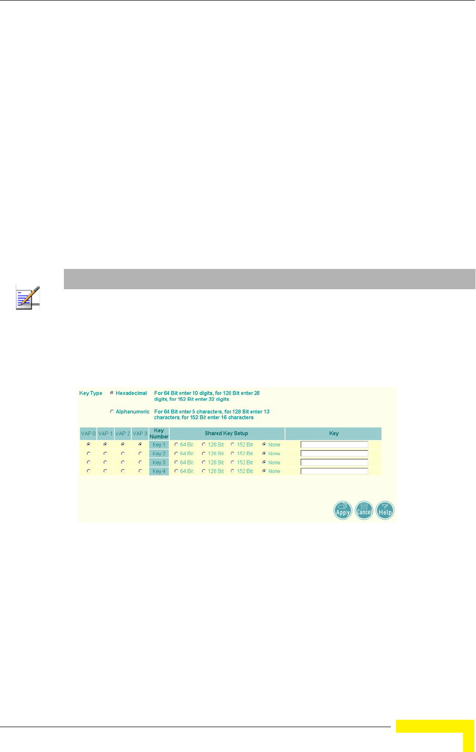
Radio Interface
BreezeMAX Wi² and BreezeACCESS Wi² System Manual 105
point. WEP uses static shared keys (fixed-length hexadecimal or alphanumeric
strings) that are manually distributed to all clients that want to use the network.
WEP is the security protocol initially specified in the IEEE 802.11 standard for
wireless communications. Unfortunately, WEP has been found to be seriously
flawed and cannot be recommended for a high level of network security. For more
robust wireless security, the access point provides WiFi Protected Access (WPA)
for improved data encryption and user authentication.
Setting up shared keys enables the basic IEEE 802.11 Wired Equivalent Privacy
(WEP) on the access point to prevent unauthorized access to the network.
If you choose to use WEP shared keys instead of an open system, be sure to define
at least one static WEP key for user authentication and data encryption. Also, be
sure that the WEP shared keys are the same for each client in the wireless
network.
To set up WEP shared keys, click Radio Settings.
Key Type – Select the preferred method of entering WEP encryption keys on the
access point and enter up to four keys:
Hexadecimal: Enter keys as 10 hexadecimal digits (0-9 and A-F) for 64 bit
keys, 26 hexadecimal digits for 128 bit keys, or 32 hexadecimal digits for 152
bit keys (802.11g radio only). This is the default setting.
NOTE
All clients share the same keys, which are used for user authentication and data encryption. Up to
four keys can be specified. These four keys are used for all VAP interfaces on the same radio.
Figure 4-24: WEP Shared Keys
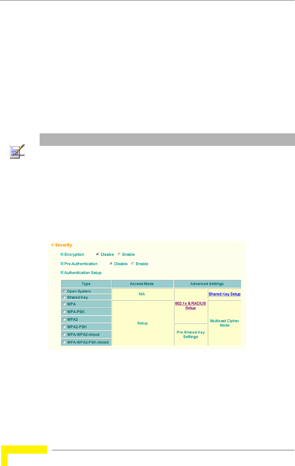
106 Operation
Chapter 4 - System Configuration
Alphanumeric: Enter keys as 5 alphanumeric characters for 64 bit keys, 13
alphanumeric characters for 128 bit keys, or 16 alphanumeric characters for
152 bit keys.
Key Number – Selects the key number to use for encryption for each VAP interface.
If the clients have all four keys configured to the same values, you can change the
encryption key to any of the four settings without having to update the client keys.
(Default: Key 1)
Shared Key Setup – Select 64 Bit, 128 Bit, or 152 Bit key length. Note that the
same size of encryption key must be supported on all wireless clients. (Default:
None)
To enable WEP shared keys for a VAP interface, click Security. Then, select the
VAP interface that will use WEP keys by clicking More, and configure the
Authentication Type Setup and Encryption fields.
Authentication Type Setup – Sets the access point to communicate as an open
system that accepts network access attempts from any client, or with clients
using pre-configured static shared keys. (Default: Open System)
NOTE
Key index and type must match that configured on the clients.
In a mixed-mode environment with clients using static WEP keys and WPA, select WEP transmit
key index 2, 3, or 4. The access point uses transmit key index 1 for the generation of dynamic
keys.
Figure 4-25: Security - Shared Keys

Radio Interface
BreezeMAX Wi² and BreezeACCESS Wi² System Manual 107
Open System: If you don’t set up any other security mechanism on the access
point, the network has no protection and is open to all users. This is the
default setting.
Shared Key: Sets the access point to use WEP shared keys. If this option is
selected, you must configure at least one key on the access point and all
clients.
Encryption – Enable or disable the access point to use data encryption (WEP,
TKIP, or AES). If this option is selected when using static WEP keys, you must
configure at
least one key on the access point and all clients. (Default: Disabled)
4.4.2.2.1 CLI Commands for WEP Shared Key Security
To enable WEP shared key security for the 802.11g interface, use the interface
wireless g command from the CLI configuration mode to access the interface
mode for the 802.11g radio. First use the key command to define up to four WEP
keys that can be used for all VAP interfaces on the radio. Then use the vap
command to access each VAP interface to configure other security settings.
From the VAP interface configuration mode, use the auth command to enable
WEP shared-key authentication, which enables encryption automatically. Then
set one key as the transmit key for the VAP interface using the transmit-key
command. To view the current security settings, use the show interface wireless
g [0-3] command from the Exec mode.
4.4.2.2.2 CLI Commands for WEP over 802.1X Security
Use the vap command to access each VAP interface to configure the security
settings. First set 802.1X to required using the 802.1x command and set the
802.1X key refresh rates. Then, use the auth command to select open system
authentication and the encryption command to enable data encryption. To view
NOTE
To use 802.1X on wireless clients requires a network card driver and 802.1X client software that
supports the EAP authentication type that you want to use. Windows 2000 SP3 or later and
Windows XP provide 802.1X client support. Windows XP also provides native WPA support. Other
systems require additional client software to support 802.1X and WPA.
NOTE
You must enable data encryption through the web or CLI in order to enable all types of encryption
(WEP, TKIP, or AES) in the AP.

108 Operation
Chapter 4 - System Configuration
the current security settings, use the show interface wireless g [0-3] command
(not shown in example).
4.4.2.3 WiFi Protected Access (WPA)
WPA employs a combination of several technologies to provide an enhanced
security solution for 802.11 wireless networks.
The access point supports the following WPA components and features:
IEEE 802.1X and the Extensible Authentication Protocol
(EAP):
WPA employs
802.1X as its basic framework for user authentication and dynamic key
management. The 802.1X client and RADIUS server should use an appropriate
EAP type—such as EAP-TLS (Transport Layer Security), EAP-TTLS (Tunneled
TLS), or PEAP (Protected EAP)—for strongest authentication. Working together,
these protocols provide “mutual authentication” between a client, the access
point, and a RADIUS server that prevents users from accidentally joining a rogue
network. Only when a RADIUS server has authenticated a user’s credentials will
encryption keys be sent to the access point and client.
Temporal Key Integrity Protocol (TKIP): WPA specifies TKIP as the data
encryption method to replace WEP. TKIP avoids the problems of WEP static keys
by dynamically changing data encryption keys. Basically, TKIP starts with a
master (temporal) key for each user session and then mathematically generates
other keys to encrypt each data packet. TKIP provides further data encryption
enhancements by including a message integrity check for each packet and a
re-keying mechanism, which periodically changes the master key.
WPA Pre-Shared Key Mode (WPA-PSK, WPA2-PSK): For enterprise deployment,
WPA requires a RADIUS authentication server to be configured on the wired
network. However, for small office networks that may not have the resources to
configure and maintain a RADIUS server, WPA provides a simple operating mode
that uses just a pre-shared password for network access. The Pre-Shared Key
mode uses a common password for user authentication that is manually entered
on the access point and all wireless clients. The PSK mode uses the same TKIP
Enterprise AP(if-wireless g)#vap 0
Enterprise AP(if-wireless g: VAP[0])#802.1X required 191
Enterprise AP(if-wireless g: VAP[0])#802.1X session-timeout 300
Enterprise AP(if-wireless g: VAP[0])#auth open-system 230
Enterprise AP(if-wireless g: VAP[0])#encryption 232
Enterprise AP(if-wireless g: VAP[0])#
NOTE
To implement WPA on wireless clients requires a WPA-enabled network card driver and 802.1X
client software that supports the EAP authentication type that you want to use. Windows XP
provides native WPA support, other systems require additional software.

Radio Interface
BreezeMAX Wi² and BreezeACCESS Wi² System Manual 109
packet encryption and key management as WPA in the enterprise, providing a
robust and manageable alternative for small networks.
Mixed WPA and WEP Client Support: WPA enables the access point to indicate
its supported encryption and authentication mechanisms to clients using its
beacon signal. WPA-compatible clients can likewise respond to indicate their WPA
support. This enables the access point to determine which clients are using WPA
security and which are using legacy WEP. The access point uses TKIP unicast
data encryption keys for WPA clients and WEP unicast keys for WEP clients. The
global encryption key for multicast and broadcast traffic must be the same for all
clients, therefore it restricts encryption to a WEP key.
When access is opened to both WPA and WEP clients, no authentication is
provided for the WEP clients through shared keys. To support authentication for
WEP clients in this mixed mode configuration, you can use either MAC
authentication or 802.1X authentication.
WPA2 – WPA was introduced as an interim solution for the vulnerability of WEP
pending the ratification of the IEEE 802.11i wireless security standard. In effect,
the WPA security features are a subset of the 802.11i standard. WPA2 includes
the now ratified 802.11i standard, but also offers backward compatibility with
WPA. Therefore, WPA2 includes the same 802.1X and PSK modes of operation and
support for TKIP encryption. The main differences and enhancements in WPA2
can be summarized as follows:
Advanced Encryption Standard (AES): WPA2 uses AES Counter-Mode
encryption with Cipher Block Chaining Message Authentication Code
(CBC-MAC) for message integrity. The AES Counter-Mode/CBCMAC Protocol
(AES-CCMP) provides extremely robust data confidentiality using a 128-bit
key. The AES-CCMP encryption cipher is specified as a standard requirement
for WPA2. However, the computational intensive operations of AES-CCMP
requires hardware support on client devices. Therefore to implement WPA2 in
the network, wireless clients must be upgraded to WPA2-compliant hardware.
WPA2 Mixed-Mode: WPA2 defines a transitional mode of operation for
networks moving from WPA security to WPA2. WPA2 Mixed Mode allows both
WPA and WPA2 clients to associate to a common SSID interface. In mixed
mode, the unicast encryption cipher (TKIP or AES-CCMP) is negotiated for
each client. The access point advertises its supported encryption ciphers in
beacon frames and probe responses. WPA and WPA2 clients select the cipher
they support and return the choice in the association request to the access
point. For mixed-mode operation, the cipher used for broadcast frames is
always TKIP. WEP encryption is not allowed.

110 Operation
Chapter 4 - System Configuration
Key Caching: WPA2 provides fast roaming for authenticated clients by
retaining keys and other security information in a cache, so that if a client
roams away from an access point and then returns, re-authentication is not
required. When a WPA2 client is first authenticated, it receives a Pairwise
Master Key (PMK) that is used to generate other keys for unicast data
encryption. This key and other client information form a Security Association
that the access point names and holds in a cache.
Preauthentication: Each time a client roams to another access point it has to
be fully re-authenticated. This authentication process is time consuming and
can disrupt applications running over the network. WPA2 includes a
mechanism, known as pre-authentication, that allows clients to roam to a new
access point and be quickly associated. The first time a client is authenticated
to a wireless network it has to be fully authenticated. When the client is about
to roam to another access point in the network, the access point sends
pre-authentication messages to the new access point that include the client’s
security association information. Then when the client sends an association
request to the new access point, the client is known to be already
authenticated, so it proceeds directly to key exchange and association.
To configure WPA, click Security, select one of the VAP interfaces by clicking
More. Select one of the WPA options in the Authentication Setup table, and then
configure the parameters displayed beneath the table.
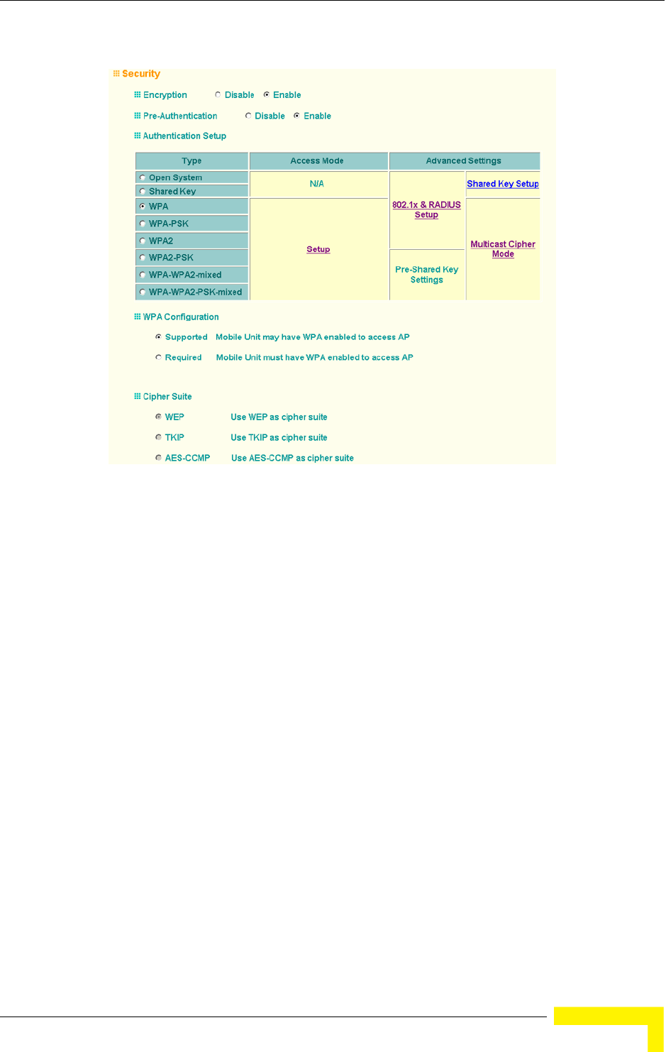
Radio Interface
BreezeMAX Wi² and BreezeACCESS Wi² System Manual 111
The WPA configuration parameters are described below:
Encryption – You must enable data encryption in order to enable all types of
encryption (WEP, TKIP, or AES) in the access point.
Pre-Authentication – When using WPA2 over 802.1X, pre-authentication can be
enabled, which allows clients to roam to a new access point and be quickly
associated without performing full 802.1X authentication. (Default: Disabled)
Authentication Setup – To use WPA or WPA2, set the access point to one of the
following options. If a WPA/WPA2 mode that operates over 802.1X is selected
(WPA, WPA2, or WPA-WPA2-mixed), the 802.1X settings and RADIUS server
details need to be configured. Be sure you have also configured a RADIUS server
on the network before enabling authentication. If a WPA/WPA2 Pre-shared Key
mode is selected (WPA-PSK, WPA2-PSK, or WPA-WPA2 PSK-Mixed), be sure to
specify the key string.
WPA: Clients using WPA over 802.1X are accepted for authentication.
Figure 4-26: Security - WPA Configuration

112 Operation
Chapter 4 - System Configuration
WPA-PSK: Clients using WPA with a Pre-shared Key are accepted for
authentication.
WPA2: Clients using WPA2 over 802.1X are accepted for authentication.
WPA2-PSK: Clients using WPA2 with a Pre-shared Key are accepted for
authentication.
WPA-WPA2-mixed: Clients using WPA or WPA2 over 802.1X are accepted for
authentication.
WPA-WPA2-PSK-mixed: Clients using WPA or WPA2 with a Pre-shared Key are
accepted for authentication.
WPA Configuration – Each VAP interface can be configured to allow only
WPA-enabled clients to access the network (Required), or to allow access to both
WPA and WEP clients (Supported). (Default: Required)
Cipher Suite – Selects an encryption method for the global key used for multicast
and broadcast traffic, which is supported by all wireless clients.
WEP: WEP is used as the multicast encryption cipher. You should select WEP
only when both WPA and WEP clients are supported.
TKIP: TKIP is used as the multicast encryption cipher.
AES-CCMP: AES-CCMP is used as the multicast encryption cipher. AES-CCMP
is the standard encryption cipher required for WPA2.
WPA Pre-Shared Key Type – If the WPA or WPA2 pre-shared-key mode is used, all
wireless clients must be configured with the same key to communicate with the
AP.
Hexadecimal – Enter a key as a string of 64 hexadecimal numbers.
Alphanumeric – Enter a key as an easy-to-remember form of letters and
numbers. The string must be from 8 to 63 characters, which can include
spaces.
The configuration settings for WPA are summarized in Table 4-8:

Radio Interface
BreezeMAX Wi² and BreezeACCESS Wi² System Manual 113
4.4.2.3.1 CLI Commands for WPA Using Pre-shared Key Security
From the VAP interface configuration mode, use the auth wpa-psk required
command to enable WPA Pre-shared Key security. To enter a key value, use the
wpa-pre-shared-key command to specify a hexadecimal or alphanumeric key. To
view the current security settings, use the show interface wireless a [0-3] or
show interface wireless g [0-3] command (not shown in example).
4.4.2.3.2 CLI Commands for WPA Over 802.1X Security
From the VAP interface configuration mode, use the auth wpa required command
to select WPA over 802.1X security. Then set the 802.1X key refresh rates. To view
Table 4-8: WPA Configuration Settings
WPA and WPA2 pre-shared key only WPA and WPA2 over 802.1X
Encryption: Enabled Encryption: Enabled
Authentication Setup: WPA-PSK, WPA2-PSK, or
WPA-WPA2-mixed
Authentication Setup: WPA, WPA2,
WPA-WPA2-mixed
Cipher Suite: WEP/TKIP/AES-CCMP Cipher Suite: WEP/TKIP/AES-CCMP
WPA Pre-shared Key Type: Hex/ASCII (requires RADIUS server to be specified)
1:You must enable data encryption in order to enable all types of encryption in the access point.
2:Select TKIP when any WPA clients do not support AES. Select AES only if all clients support AES.
Enterprise AP(config)#interface wireless g 210
Enter Wireless configuration commands, one per line.
Enterprise AP(if-wireless g)#vap 0
Enterprise AP(if-wireless g: VAP[0])#wpa-pre-shared-key
passphrase-key agoodsecret 235
Enterprise AP(if-wireless g: VAP[0])#auth wpa-psk required
Data Encryption is set to Enabled.
WPA2 Clients Mode is set to Disabled.
WPA Clients Mode is set to Required.
WPA Multicast Cipher is set to TKIP.
WPA Unicast Cipher can accept TKIP only.
WPA Authentication is set to Pre-Shared Key.
Enterprise AP(if-wireless g: VAP[0])#

114 Operation
Chapter 4 - System Configuration
the current security settings, use the show interface wireless a [0-3] or show
interface wireless g [0-3] command (not shown in example).
4.4.2.4 Configuring 802.1X
IEEE 802.1X is a standard framework for network access control that uses a
central RADIUS server for user authentication. This control feature prevents
unauthorized access to the network by requiring an 802.1X client application to
submit user credentials for authentication. The 802.1X standard uses the
Extensible Authentication Protocol (EAP) to pass user credentials (either digital
certificates, user names and passwords, or other) from the client to the RADIUS
server. Client authentication is then verified on the RADIUS server before the
access point grants client access to the network.
The 802.1X EAP packets are also used to pass dynamic unicast session keys and
static broadcast keys to wireless clients. Session keys are unique to each client
and are used to encrypt and correlate traffic passing between a specific client and
the access point. You can also enable broadcast key rotation, so the access point
provides a dynamic broadcast key and changes it at a specified interval.
Open the Security page, and click More for one of the VAP interfaces.
Enterprise AP(config)#interface wireless g 210
Enter Wireless configuration commands, one per line.
Enterprise AP(if-wireless g)#vap 0
Enterprise AP(if-wireless g: VAP[0])#auth wpa required
Data Encryption is set to Enabled.
WPA2 Clients mode is set to Disabled.
WPA Clients Mode is set to Required.
WPA Multicast Cipher is set to TKIP.
WPA Unicast Cipher can accept TKIP only.
WPA Authentication is set to 802.1X Required.
Enterprise AP(if-wireless g: VAP[0])#802.1X broadcast-key-refresh-rate 5
Enterprise AP(if-wireless g: VAP[0])#802.1X
session-key-refresh-rate 5
Enterprise AP(if-wireless g: VAP[0])#802.1X session-timeout 300
Enterprise AP(if-wireless g: VAP[0])#
Figure 4-27: 802.1X Configuration
Radio Interface
BreezeMAX Wi² and BreezeACCESS Wi² System Manual 115
You can enable 802.1X as optionally supported or as required to enhance the
security of the wireless network. (Default: Disable)
Disable: The AP does not support 802.1X authentication for any wireless
client. After successful wireless association with the access point, each client
is allowed to access the network.
Supported: The access point supports 802.1X authentication only for clients
initiating the 802.1X authentication process (i.e., the access point does not
initiate 802.1X authentication). For clients initiating 802.1X, only those
successfully authenticated are allowed to access the network. For those clients
not initiating 802.1X, access to the network is allowed after successful
wireless association with the access point. The 802.1X supported mode allows
access for clients not using WPA or WPA2 security.
Required: The access point enforces 802.1X authentication for all associated
wireless clients. If 802.1X authentication is not initiated by a client, the AP will
initiate authentication. Only those clients successfully authenticated with
802.1X are allowed to access the network.
4.4.2.4.1 CLI Commands for 802.1X Authentication
Use the 802.1X supported command from the VAP interface mode to enable
802.1X authentication. Set the session and broadcast key refresh rate, and the
re-authentication timeout. To display the current settings, use the show
interface wireless command from the Exec mode (not shown in the example).
NOTE
If 802.1X is enabled on the access point, then RADIUS setup must be completed (see “RADIUS”
on page 4-48.).
Enterprise AP(if-wireless g: VAP[0])#802.1X supported 191
Enterprise AP(if-wireless g: VAP[0])#802.1X broadcast-key-refresh-rate 5
Enterprise AP(if-wireless g: VAP[0])#802.1X session-key-refresh-rate 5
Enterprise AP(if-wireless g: VAP[0])#802.1X session-timeout 300
Enterprise AP#
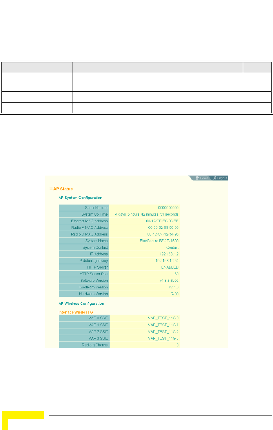
116 Operation
Chapter 4 - System Configuration
4.5 Status Information
The Status page includes information on the following items:
4.5.1 Access Point Status
The AP Status window displays basic system configuration settings, as well as the
settings for the wireless interface.
Table 4-9: Status Page Information
Menu Description Page
AP Status Displays configuration settings for the basic system and the wireless
interface
116
Station Status Shows the wireless clients currently associated with the access point 118
Event Logs Shows log messages stored in memory 120
Figure 4-28: AP Status

Status Information
BreezeMAX Wi² and BreezeACCESS Wi² System Manual 117
AP System Configuration – The AP System Configuration table displays the basic
system configuration settings:
System Up Time: Length of time the management agent has been up.
Ethernet MAC: The physical layer address for the Ethernet port.
Radio G MAC: The physical layer address for the 802.11b/g interface. System
Name: Name assigned to this system.
System Contact: Administrator responsible for the system.
IP Address: IP address of the management interface for this device.
IP Default Gateway: IP address of the gateway router between this device and
management stations that exist on other network segments.
HTTP Server: Shows if management access via HTTP is enabled.
HTTP Server Port: Shows the TCP port used by the HTTP interface.
Software Version: Shows the software version number.
Bootrom Version: Show the bootrom version number.
Hardware Version: Shows the hardware version number.
AP Wireless Configuration – The AP Wireless Configuration tables display the
radio and VAP interface settings listed below.
SSID: The service set identifier for the VAP interface.
Radio Channel: The radio channel through which the access point
communicates with wireless clients.
Encryption: The key size used for data encryption.
Authentication Type: Shows the type of authentication used.
802.1X: Shows if IEEE 802.1X access control for wireless clients is enabled.

118 Operation
Chapter 4 - System Configuration
4.5.1.0.1 CLI Commands for Displaying System Settings
To view the current access point system settings, use the show system command
from the Exec mode. To view the current radio interface settings, use the show
interface wireless a or show interface wireless g command (see page 222).
4.5.2 Station Status
The Station Status window shows the wireless clients currently associated with
the access point.
Enterprise AP#show system 149
System Information
==========================================================
Serial Number : A123456789
System Up time : 0 days, 4 hours, 33 minutes, 29 seconds
System Name : Enterprise wireless gP
System Location :
System Contact :
System Country Code : US - UNITED STATES
MAC Address : 00-30-F1-F0-9A-9C
IP Address : 192.168.1.1
Subnet Mask : 255.255.255.0
Default Gateway : 0.0.0.0
VLAN State : DISABLED
Management VLAN ID(AP): 1
IAPP State : ENABLED
DHCP Client : ENABLED
HTTP Server : ENABLED
HTTP Server Port : 80
HTTPS Server : ENABLED
HTTPS Server Port : 443
Slot Status : 802.11g only
Boot Rom Version : v2.1.6
Software Version : v4.3.3.8b02
SSH Server : ENABLED
SSH Server Port : 22
Telnet Server : ENABLED
WEB Redirect : DISABLED
DHCP Relay : DISABLED
==========================================================
Enterprise AP
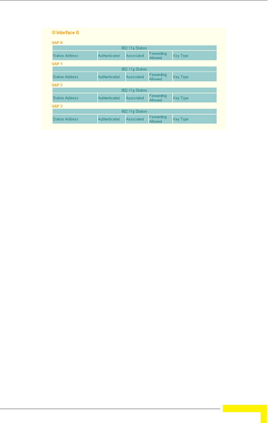
Status Information
BreezeMAX Wi² and BreezeACCESS Wi² System Manual 119
The Station Configuration page displays basic connection information for all
associated stations as described below. This page is automatically refreshed every
five seconds.
Station Address: The MAC address of the wireless client.
Authenticated: Shows if the station has been authenticated. The two basic
methods of authentication supported for 802.11 wireless networks are “open
system” and “shared key.” Open-system authentication accepts any client
attempting to connect to the access point without verifying its identity. The
shared-key approach uses Wired Equivalent Privacy (WEP) to verify client
identity by distributing a shared key to stations before attempting
authentication.
Associated: Shows if the station has been successfully associated with the
access point. Once authentication is completed, stations can associate with
the current access point, or reassociate with a new access point. The
association procedure allows the wireless system to track the location of each
mobile client, and ensure that frames destined for each client are forwarded to
the appropriate access point.
Forwarding Allowed: Shows if the station has passed 802.1X authentication
and is now allowed to forward traffic to the access point.
Key Type – Displays one of the following:
Figure 4-29: Station Status

120 Operation
Chapter 4 - System Configuration
WEP Disabled – The client is not using Wired Equivalent Privacy (WEP)
encryption keys.
Dynamic – The client is using WiFi Protected Access (802.1X or pre-shared
key mode) or using 802.1X authentication with dynamic keying.
Static – The client is using static WEP keys for encryption.
4.5.2.0.1 CLI Commands for Displaying Station Status
To view status of clients currently associated with the access point, use the show
station command from the Exec mode.
4.5.3 Event Logs
The Event Logs window shows the log messages generated by the AP and stored in
memory.
Enterprise AP#show station 224
Station Table Information
===========================================================
if-wireless G VAP [0] :
802.11g Channel : Auto
No 802.11g Channel Stations.
if-wireless G VAP [1] :
802.11g Channel : Auto
No 802.11g Channel Stations.
....
No 802.11g Channel Stations.
if-wireless G VAP [3] :
802.11g Channel : Auto
No 802.11g Channel Stations.
===========================================================
Enterprise AP#

Status Information
BreezeMAX Wi² and BreezeACCESS Wi² System Manual 121
The Event Logs table displays the following information:
Log Time: The time the log message was generated.
Event Level: The logging level associated with this message. For a description
of the various levels, see “logging level” on page 70.
Event Message: The content of the log message.
Error Messages : An example of a logged error message is: “Station Failed to
authenticate (unsupported algorithm).”
This message may be caused by any of the following conditions:
AP was set to Open Authentication, but a client sent an authentication request
frame with a Shared key.
AP was set to Shared Key Authentication, but a client sent an authentication
frame for Open System.
WEP keys do not match: When the AP uses Shared Key Authentication, but the
key used by client and access point are not the same, the frame will be
decrypted incorrectly, using the wrong algorithm and sequence number.
Figure 4-30: Event Log

122 Operation
Chapter 4 - System Configuration
4.5.3.0.1 CLI Commands for Displaying the Logging Status
From the global configuration mode, use the show logging command.
4.5.3.0.2 CLI Commands for Displaying Event Logs
To view the access point log entries, use the show event-log command from the
Exec mode. To clear all log entries from the access point, use the logging clear
command from the Global Configuration mode.
Enterprise AP#show logging 160
Logging Information
============================================
Syslog State : Enabled
Logging Console State : Enabled
Logging Level : Alert
Logging Facility Type : 16
Servers
1: 192.168.1.19, UDP Port: 514, State: Enabled
2: 0.0.0.0, UDP Port: 514, State: Disabled
3: 0.0.0.0, UDP Port: 514, State: Disabled
4: 0.0.0.0, UDP Port: 514, State: Disabled
=============================================
Enterprise AP#
Enterprise AP#show event-log 161
Mar 09 11:57:55 Information: 802.11g:11g Radio Interface Enabled
Mar 09 11:57:55 Information: 802.11g:Radio channel updated to 8
Mar 09 11:57:34 Information: 802.11g:11g Radio Interface Enabled
Mar 09 11:57:18 Information: 802.11g:11g Radio Interface Enabled
Mar 09 11:55:52 Information: SSH task: Set SSH server port to 22
Mar 09 11:55:52 Information: SSH task: Enable SSH server.
Mar 09 11:55:52 Information: Enable Telnet.
Press <n> next. <p> previous. <a> abort. <y> continue to end :
Enterprise AP#configure
Enter configuration commands, one per line. End with CTRL/Z
Enterprise AP(config)#logging clear 160
Enterprise AP#

5
Chapter 5 -
Command Line Interface
In This Chapter:
“Using the Command Line Interface” on page 125
“Entering Commands” on page 127
“Command Groups” on page 132
“General Commands” on page 134
“System Management Commands” on page 139
“System Logging Commands” on page 157
“System Clock Commands” on page 162
“DHCP Relay Commands” on page 166
“SNMP Commands” on page 168
“Flash/File Commands” on page 181
“RADIUS Client” on page 185
“802.1X Authentication” on page 191
“MAC Address Authentication” on page 194
“Filtering Commands” on page 198

124 Operation
Chapter 5 - Command Line Interface
“WDS Bridge Commands” on page 202
“Spanning Tree Commands” on page 203
“Ethernet Interface Commands” on page 204
“Wireless Interface Commands” on page 209
“Rogue AP Detection Commands” on page 226
“Wireless Security Commands” on page 230
“Link Integrity Commands” on page 238
“IAPP Commands” on page 241
“VLAN Commands” on page 242
“WMM Commands” on page 245
Using the Command Line Interface
BreezeMAX Wi² and BreezeACCESS Wi² System Manual 125
5.1 Using the Command Line Interface
5.1.1 Accessing the CLI
When accessing the management interface over a direct connection to the console
port, or via a Telnet connection, the Access Point (AP) unit can be managed by
entering command keywords and parameters at the prompt. Using AP’s
command-line interface (CLI) is very similar to entering commands on a UNIX
system.
5.1.2 Console Connection
1At the console prompt, enter the user name and password. (The default user
name is admin and the default password is smcadmin.) When the user name is
entered, the CLI displays the Enterprise AP# prompt.
2Enter the necessary commands to complete your desired tasks.
3When finished, exit the session with the “exit” command.
After connecting to the system through the console port, the login screen is
displayed:
5.1.3 Telnet Connection
Telnet operates over the IP transport protocol. In this environment, your
management station and any network device you want to manage over the
network must have a valid IP address. Valid IP addresses consist of four numbers,
0 to 255, separated by periods. Each address consists of a network portion and
host portion. For example, if the AP cannot acquire an IP address from a DHCP
server, the default IP address used by the AP, 192.168.1.1, consists of a network
portion (192.168.1) and a host portion (1).
To access the Wi2 through the console port:
Username: admin
Password:
Enterprise AP#
CAUTION
Command examples shown later in this chapter abbreviate the console prompt to “AP” for simplicity.
126 Operation
Chapter 5 - Command Line Interface
To access the AP through a Telnet session, you must first set the IP address for
the AP, and set the default gateway if you are managing the AP from a different IP
subnet. For example:
If your corporate network is connected to another network outside your office or to
the Internet, you need to apply for a registered IP address. However, if you are
attached to an isolated network, then you can use any IP address that matches
the network segment to which you are attached.
After you have configured the AP with an IP address, you can open a Telnet
session.
1From the remote host, enter the Telnet command and the IP address of the
device you want to access.
2At the prompt, enter the user name and system password. The CLI will display
the Enterprise AP# prompt to show that you are using executive access mode
(i.e., Exec).
3Enter the necessary commands to complete your desired tasks.
4When finished, exit the session with the “quit” or “exit” command.
After entering the Telnet command, the login screen is displayed:
Enterprise AP#configure
Enterprise AP(config)#interface ethernet
Enterprise AP(if-ethernet)#ip address 10.1.0.1 255.255.255.0 10.1.0.254
Enterprise AP(if-ethernet)#
To open an Telnet session:
Username: admin
Password:
Enterprise AP#
CAUTION
You can open up to four sessions to the device via Telnet.

Entering Commands
BreezeMAX Wi² and BreezeACCESS Wi² System Manual 127
5.2 Entering Commands
This section describes how to enter CLI commands.
5.2.1 Keywords and Arguments
A CLI command is a series of keywords and arguments. Keywords identify a
command, and arguments specify configuration parameters. For example, in the
command “show interfaces ethernet,” show and interfaces are keywords, and
ethernet is an argument that specifies the interface type.
You can enter commands as follows:
To enter a simple command, enter the command keyword.
To enter commands that require parameters, enter the required parameters
after the command keyword. For example, to set a password for the
administrator, enter:
Enterprise AP(config)#username smith
5.2.2 Minimum Abbreviation
The CLI accepts a minimum number of characters that uniquely identify a
command. For example, the command “configure” can be entered as con. If an
entry is ambiguous, the system will prompt for further input.
5.2.3 Command Completion
If you terminate input with a Tab key, the CLI will print the remaining characters
of a partial keyword up to the point of ambiguity. In the “configure” example,
typing con followed by a tab will result in printing the command up to
“configure.”
5.2.4 Getting Help on Commands
You can display a brief description of the help system by entering the help
command. You can also display command syntax by following a command with
the “?” character to list keywords or parameters.
5.2.4.1 Showing Commands
If you enter a “?” at the command prompt, the system will display the first level of
keywords for the current configuration mode (Exec, Global Configuration, or

128 Operation
Chapter 5 - Command Line Interface
Interface). You can also display a list of valid keywords for a specific command.
For example, the command “show ?” displays a list of possible show commands:
The command “show interface ?” will display the following information:
5.2.5 Partial Keyword Lookup
If you terminate a partial keyword with a question mark, alternatives that match
the initial letters are provided. (Remember not to leave a space between the
command and question mark.) For example “s?” shows all the keywords starting
with “s.”
5.2.6 Negating the Effect of Commands
For many configuration commands you can enter the prefix keyword “no” to
cancel the effect of a command or reset the configuration to the default value. For
example, the logging command will log system messages to a host server. To
disable logging, specify the no logging command. This guide describes the
negation effect for all applicable commands.
Enterprise AP#show ?
APmanagement Show management AP information.
authentication Show Authentication parameters
bootfile Show bootfile name
config System snapshot for tech support
dhcp-relay Show DHCP Relay Configuration
event-log Show event log on console
filters Show filters
hardware Show hardware version
history Display the session history
interface Show interface information
line TTY line information
link-integrity Show link integrity information
logging Show the logging buffers
radius Show radius server
rogue-ap Show Rogue ap Stations
snmp Show snmp configuration
sntp Show sntp configuration
station Show 802.11 station table
system Show system information
version Show system version
Enterprise AP#show
Enterprise AP#show interface ?
ethernet Show Ethernet interface
wireless Show wireless interface
<cr>
Enterprise AP#show interface
Enterprise AP#show s?
snmp sntp station system
Enterprise AP#show s

Entering Commands
BreezeMAX Wi² and BreezeACCESS Wi² System Manual 129
5.2.7 Using Command History
The CLI maintains a history of commands that have been entered. You can scroll
back through the history of commands by pressing the up arrow key. Any
command displayed in the history list can be executed again, or first modified and
then executed.
Using the show history command displays a longer list of recently executed
commands.
5.2.8 Understanding Command Modes
The command set is divided into Exec and Configuration classes. Exec commands
generally display information on system status or clear statistical counters.
Configuration commands, on the other hand, modify interface parameters or
enable certain functions. These classes are further divided into different modes.
Available commands depend on the selected mode. You can always enter a
question mark “?” at the prompt to display a list of the commands available for
the current mode. The command classes and associated modes are displayed in
Table 5-1:
5.2.9 Exec Commands
When you open a new console session on an AP, the system enters Exec command
mode. Only a limited number of the commands are available in this mode. You
can access all other commands only from the configuration mode. To access Exec
mode, open a new console session with the user name admin. The command
prompt displays as Enterprise AP# for Exec mode.
Table 5-1: Command Classes and Associated Modes
Class Mode
Exec Privileged
Configuration Global
Interface-ethernet
Interface-wireless
Interface-wireless-vap
Username: admin
Password: [system login password]
Enterprise AP#

130 Operation
Chapter 5 - Command Line Interface
5.2.10 Configuration Commands
Configuration commands are used to modify AP settings. These commands modify
the running configuration and are saved in memory.
The configuration commands are organized into four different modes:
Global Configuration (GC) - These commands modify the system level
configuration, and include commands such as username and password.
Interface-Ethernet Configuration (IC-E) - These commands modify the
Ethernet port configuration, and include command such as dns and ip.
Interface-Wireless Configuration (IC-W) - These commands modify the wireless
port configuration of global parameters for the radio, and include commands
such as channel and transmit-power.
Interface-Wireless Virtual Access Point Configuration (IC-W-VAP) - These
commands modify the wireless port configuration for each VAP, and include
commands such as ssid and authentication.
To enter the Global Configuration mode, enter the command configure in Exec
mode. The system prompt will change to “Enterprise AP(config)#” which gives you
access privilege to all Global Configuration commands.
To enter Interface mode, you must enter the “interface ethernet,” or “interface
wireless a,” or “interface wireless g” command while in Global Configuration
mode. The system prompt will change to “Enterprise AP(if-ethernet)#,” or
Enterprise AP(if-wireless)” indicating that you have access privileges to the
associated commands. You can use the end command to return to the Exec mode.
5.2.11 Command Line Processing
Commands are not case sensitive. You can abbreviate commands and parameters
as long as they contain enough letters to differentiate them from any other
currently available commands or parameters. You can use the Tab key to
complete partial commands, or enter a partial command followed by the “?”
Enterprise AP#configure
Enterprise AP(config)#
Enterprise AP(config)#interface ethernet
Enterprise AP(if-ethernet)#

Entering Commands
BreezeMAX Wi² and BreezeACCESS Wi² System Manual 131
character to display a list of possible matches. You can also use the following
editing keystrokes for command-line processing:
Table 5-2: Keystroke Commands
Keystroke Function
Ctrl-A Shifts cursor to start of command line.
Ctrl-B Shifts cursor to the left one character.
Ctrl-C Terminates a task and displays the command prompt.
Ctrl-E Shifts cursor to end of command line.
Ctrl-F Shifts cursor to the right one character.
Ctrl-K Deletes from cursor to the end of the command line.
Ctrl-L Repeats current command line on a new line.
Ctrl-N Enters the next command line in the history buffer.
Ctrl-P Shows the last command.
Ctrl-R Repeats current command line on a new line.
Ctrl-U Deletes the entire line.
Ctrl-W Deletes the last word typed.
Esc-B Moves the cursor backward one word.
Esc-D Deletes from the cursor to the end of the word.
Esc-F Moves the cursor forward one word.
Delete key or
backspace key
Erases a mistake when entering a command.

132 Operation
Chapter 5 - Command Line Interface
5.3 Command Groups
The system commands can be broken down into the functional groups shown
below.
The access mode shown in the following tables is indicated by these abbreviations:
Exec (Executive Mode), GC (Global Configuration), IC-E (Interface-Ethernet
Table 5-3: Command Group
Command Group Description Page
General Basic commands for entering configuration mode, restarting the system, or
quitting the CLI
134
System Management Controls user name, password, web browser management options, and a
variety of other system information
139
System Logging Configures system logging parameters 157
System Clock Configures SNTP and system clock settings 162
DHCP Relay Configures the AP to send DHCP requests from clients to specified servers 166
SNMP Configures community access strings and trap managers 168
Flash/File Manages code image or AP configuration files 181
RADIUS Configures the RADIUS client used with 802.1X authentication 184
802.1X Authentication Configures 802.1X authentication 191
MAC Address
Authentication
Configures MAC address authentication 194
Filtering Filters communications between wireless clients, controls access to the
management interface from wireless clients, and filters traffic using specific
Ethernet protocol types
198
WDS Bridge Not applicable for the current release 202
Spanning Tree Not applicable for the current release 203
Ethernet Interface Configures connection parameters for the Ethernet interface 204
Wireless Interface Configures radio interface settings 209
Wireless Security Configures radio interface security and encryption settings 226
Rogue AP Detection Configures settings for the detection of rogue APs in the network 226
Link Integrity Configures a link check to a host device on the wired network 238
IAPP Enables roaming between multi-vendor APs 241
VLANs Configures VLAN membership 242
WMM Configures WMM quality of service parameters 245

Command Groups
BreezeMAX Wi² and BreezeACCESS Wi² System Manual 133
Configuration), IC-W (Interface-Wireless Configuration), and IC-W-VAP
(Interface-Wireless VAP Configuration).

134 Operation
Chapter 5 - Command Line Interface
5.4 General Commands
Table 5-4: General Commands
Command Function Mode Page
configure Activates global configuration mode Exec 135
end Returns to previous configuration mode GC, IC 135
exit Returns to the previous configuration mode, or exits the CLI any 135
ping Sends ICMP echo request packets to another node on the network Exec 136
reset Restarts the system Exec 136
show history Shows the command history buffer Exec 137
show line Shows the configuration settings for the console port Exec 137

General Commands
BreezeMAX Wi² and BreezeACCESS Wi² System Manual 135
5.4.1 configure
This command activates Global Configuration mode. You must enter this mode to
modify most of the settings on the AP. You must also enter Global Configuration
mode prior to enabling the context modes for Interface Configuration. see “Using
the Command Line Interface” on page 5-125.
Default Setting
None
Command Mode
Exec
Example
Related Commands
end (page 135)
5.4.2 end
This command returns to the previous configuration mode.
Default Setting
None
Command Mode
Global Configuration, Interface Configuration
Example
This example shows how to return to the Configuration mode from the Interface
Configuration mode:
5.4.3 exit
This command returns to the Exec mode or exits the configuration program.
Enterprise AP#configure
Enterprise AP(config)#
Enterprise AP(if-ethernet)#end
Enterprise AP(config)#

136 Operation
Chapter 5 - Command Line Interface
Default Setting
None
Command Mode
Any
Example
This example shows how to return to the Exec mode from the Interface
Configuration mode, and then quit the CLI session:
5.4.4 ping
This command sends ICMP echo request packets to another node on the network.
Syntax
ping <host_name | ip_address>
•host_name - Alias of the host.
•ip_address - IP address of the host.
Default Setting
None
Command Mode
Exec
Command Usage
• Use the ping command to see if another site on the network can be reached.
• The following are some results of the ping command:
-Normal response - The normal response occurs in one to ten seconds, depending on network
traffic.
-Destination does not respond - If the host does not respond, a “timeout” appears in ten
seconds.
-Destination unreachable - The gateway for this destination indicates that the destination is
unreachable.
-Network or host unreachable - The gateway found no corresponding entry in the route table.
• Press <Esc> to stop pinging.
Example
5.4.5 reset
This command restarts the system or restores the factory default settings.
Enterprise AP(if-ethernet)#exit
Enterprise AP#exit
CLI session with the Access Point is now closed
Username:
Enterprise AP#ping 10.1.0.19
192.168.1.19 is alive
Enterprise AP#

General Commands
BreezeMAX Wi² and BreezeACCESS Wi² System Manual 137
Syntax
reset <board | configuration>
•board - Reboots the system.
•configuration - Resets the configuration settings to the factory defaults, and then reboots the
system.
Default Setting
None
Command Mode
Exec
Command Usage
When the system is restarted, it will always run the Power-On Self-Test.
Example
This example shows how to reset the system:
5.4.6 show history
This command shows the contents of the command history buffer.
Default Setting
None
Command Mode
Exec
Command Usage
• The history buffer size is fixed at 10 commands.
• Use the up or down arrow keys to scroll through the commands in the history buffer.
Example
In this example, the show history command lists the contents of the command
history buffer:
5.4.7 show line
This command displays the console port’s configuration settings.
Enterprise AP#reset board
Reboot system now? <y/n>: y
Enterprise AP#show history
config
exit
show history
Enterprise AP#

138 Operation
Chapter 5 - Command Line Interface
Command Mode
Exec
Example
The console port settings are fixed at the values shown below.
Enterprise AP#show line
Console Line Information
======================================================
databits : 8
parity : none
speed : 9600
stop bits : 1
======================================================
Enterprise AP#

System Management Commands
BreezeMAX Wi² and BreezeACCESS Wi² System Manual 139
5.5 System Management Commands
These commands are used to configure the user name, password, system logs,
browser management options, clock settings, and a variety of other system
information.
Table 5-5: System Management Commands
Command Function Mode Page
Country Setting
country Sets the AP country code Exec 140
Device Designation
prompt Customizes the command line prompt GC 141
system name Specifies the host name for the AP GC 142
snmp-server contact Sets the system contact string GC 169
snmp-server location Sets the system location string GC 169
Management Access
username Configures the user name for management access GC 142
password Specifies the password for management access GC 143
ip ssh-server enable Enables the Secure Shell server IC-E 143
ip ssh-server port Sets the Secure Shell port IC-E 144
ip telnet-server enable Enables the Telnet server IC-E 144
APmgmtIP Specifies an IP address or range of addresses allowed access to
the management interface
GC 147
APmgmtUI Enables or disables SNMP, Telnet or web management access GC 148
show APmanagement Shows the AP management configuration Exec 148
Web Server
ip http port Specifies the port to be used by the web browser interface GC 144
ip http server Allows the AP to be monitored or configured from a browser GC 145
ip http session-timeout Sets the timeout for the web browser interface GC 145
ip https port Specifies the UDP port number used for a secure HTTP
connection to the AP’s Web interface
GC 146
ip https server Enables the secure HTTP server on the AP GC 146
System Status
show system Displays system information Exec 149
show version Displays version information for the system Exec 150

140 Operation
Chapter 5 - Command Line Interface
5.5.1 country
This command configures the AP’s country code, which identifies the country of
operation and sets the authorized radio channels.
Syntax
country <country_code>
country_code - A two character code that identifies the country of operation. See the following
table for a full list of codes.
show config Displays detailed configuration information for the system Exec 151
show hardware Displays the AP’s hardware version Exec 156
Table 5-6: Country Codes
Country Code Country Code Country Code Country Code
Albania AL Dominican
Republic
DO Kuwait KW Romania RO
Algeria DZ Ecuador EC Latvia LV Russia RU
Argentina AR Egypt EG Lebanon LB Saudi Arabia SA
Armenia AM Estonia EE Liechtenstein LI Singapore SG
Australia AU Finland FI Lithuania LT Slovak Republic SK
Austria AT France FR Macao MO Spain ES
Azerbaijan AZ Georgia GE Macedonia MK Sweden SE
Bahrain BH Germany DE Malaysia MY Switzerland CH
Belarus BY Greece GR Malta MT Syria SY
Belgium BE Guatemala GT Mexico MX Taiwan TW
Honduras HN Monaco MC Thailand TH
Belize BZ Hong Kong HK Morocco MA Trinidad &
Tobago
TT
Bolivia BO Hungary HU Netherlands NL Tunisia TN
Brazil BR Iceland IS New Zealand NZ Turkey TR
Brunei
Darussalam
BN India IN Norway NO Ukraine UA
Bulgaria BG Indonesia ID Qatar QA United Arab
Emirates
AE
Canada CA Iran IR Oman OM United Kingdom GB
Table 5-5: System Management Commands
Command Function Mode Page

System Management Commands
BreezeMAX Wi² and BreezeACCESS Wi² System Manual 141
Default Setting
US - for units sold in the United States
99 (no country set) - for units sold in other countries
Command Mode
Exec
Command Usage
• If you purchased an AP outside of the United States, the country code must be set before radio
functions are enabled.
• The available Country Code settings can be displayed by using the country ? command.
Example
5.5.2 prompt
This command customizes the CLI prompt. Use the no form to restore the default
prompt.
Syntax
prompt <string>
no prompt
string - Any alphanumeric string to use for the CLI prompt. (Maximum length: 32 characters)
Chile CL Ireland IE Pakistan PK United States US
China CN Israel IL Panama PA Uruguay UY
Colombia CO Italy IT Peru PE Uzbekistan UZ
Costa Rica CR Japan JP Philippines PH Yemen YE
Croatia HR Jordan JO Poland PL Venezuela VE
Cyprus CY Kazakhstan KZ Portugal PT Vietnam VN
Czech
Republic
CZ North Korea KP Puerto Rico PR Zimbabwe ZW
Denmark DK Korea
Republic
KR Slovenia SI
Elsalvador SV Luxembourg LU South Africa ZA
Enterprise AP#country tw
Enterprise AP#
Table 5-6: Country Codes

142 Operation
Chapter 5 - Command Line Interface
Default Setting
Enterprise AP
Command Mode
Global Configuration
Example
5.5.3 system name
This command specifies or modifies the system name for this device. Use the no
form to restore the default system name.
Syntax
system name <name>
no system name
name - The name of this host.
(Maximum length: 32 characters)
Default Setting
Enterprise AP
Command Mode
Global Configuration
Example
5.5.4 username
This command configures the user name for management access.
Syntax
username <name>
name - The name of the user.
(Length: 3-16 characters, case sensitive)
Enterprise AP(config)#prompt RD2
RD2(config)#
Enterprise AP(config)#system name AP
Enterprise AP(config)#

System Management Commands
BreezeMAX Wi² and BreezeACCESS Wi² System Manual 143
Default Setting
admin
Command Mode
Global Configuration
Example
5.5.5 password
After initially logging onto the system, you should set the password. Remember to
record it in a safe place. Use the no form to reset the default password.
Syntax
password <password>
no password
password - Password for management access.
(Length: 3-16 characters, case sensitive)
Default Setting
smcadmin
Command Mode
Global Configuration
Example
5.5.6 ip ssh-server enable
This command enables the Secure Shell server. Use the no form to disable the
server.
Syntax
ip ssh-server enable
no ip ssh-server
Default Setting
Interface enabled
Command Mode
Interface Configuration (Ethernet)
Command Usage
The AP supports Secure Shell version 2.0 only.
Enterprise AP(config)#username bob
Enterprise AP(config)#
Enterprise AP(config)#password
Enterprise AP(config)#

144 Operation
Chapter 5 - Command Line Interface
After boot up, the SSH server needs about two minutes to generate host
encryption keys. The SSH server is disabled while the keys are being
generated. The show system command displays the status of the SSH server.
Example
5.5.7 ip ssh-server port
This command sets the Secure Shell server port. Use the no form to disable the
server.
Syntax
ip ssh-server port <port-number>
•port-number - The UDP port used by the SSH server. (Range: 1-65535)
Default Setting
22
Command Mode
Interface Configuration (Ethernet)
Example
5.5.8 ip telnet-server enable
This command enables the Telnet server. Use the no form to disable the server.
Syntax
ip telnet-server enable
no ip telnet-server
Default Setting
Interface enabled
Command Mode
Interface Configuration (Ethernet)
Example
5.5.9 ip http port
This command specifies the TCP port number used by the web browser interface.
Use the no form to use the default port.
Enterprise AP(if-ethernet)#ip ssh-server enable
Enterprise AP(if-ethernet)#
Enterprise AP(if-ethernet)#ip ssh-server port 1124
Enterprise AP(if-ethernet)#
Enterprise AP(if-ethernet)#ip telnet-server enable
Enterprise AP(if-ethernet)#

System Management Commands
BreezeMAX Wi² and BreezeACCESS Wi² System Manual 145
Syntax
ip http port <port-number>
no ip http port
port-number - The TCP port to be used by the browser interface. (Range: 1024-65535)
Default Setting
80
Command Mode
Global Configuration
Example
Related Commands
ip http server (page 145)
5.5.10 ip http server
This command allows this device to be monitored or configured from a browser.
Use the no form to disable this function.
Syntax
ip http server
no ip http server
Default Setting
Enabled
Command Mode
Global Configuration
Example
Related Commands
ip http port (page 144)
5.5.11 ip http session-timeout
This command sets the time limit for an idle web interface session.
Syntax
ip http session-timeout <time>
time - Sets the web interface session timeout.
(Range: 0 - 1800 seconds, 0 means disabled)
Enterprise AP(config)#ip http port 769
Enterprise AP(config)#
Enterprise AP(config)#ip http server
Enterprise AP(config)#

146 Operation
Chapter 5 - Command Line Interface
Default Setting
300 seconds
Command Mode
Global Configuration
Example
Related Commands
ip http port (page 144)
5.5.12 ip https port
Use this command to specify the UDP port number used for HTTPS/SSL
connection to the AP’s Web interface. Use the no form to restore the default port.
Syntax
ip https port <port_number>
no ip https port
port_number – The UDP port used for HTTPS/SSL.
(Range: 80, 1024-65535)
Default Setting
443
Command Mode
Global Configuration
Command Usage
• You cannot configure the HTTP and HTTPS servers to use the same port.
• To avoid using common reserved TCP port numbers below 1024, the configurable range is
restricted to 443 and between 1024 and 65535.
• If you change the HTTPS port number, clients attempting to connect to the HTTPS server must
specify the port number in the URL, in this format:
https://device:port_number
Example
5.5.13 ip https server
Use this command to enable the secure hypertext transfer protocol (HTTPS) over
the Secure Socket Layer (SSL), providing secure access (i.e., an encrypted
connection) to the AP’s Web interface. Use the no form to disable this function.
Enterprise AP(config)#ip http session-timeout 0
Enterprise AP(config)#
Enterprise AP(config)#ip https port 1234
Enterprise AP(config)#
System Management Commands
BreezeMAX Wi² and BreezeACCESS Wi² System Manual 147
Syntax
ip https server
no ip https server
Default Setting
Enabled
Command Mode
Global Configuration
Command Usage
• Both HTTP and HTTPS service can be enabled independently.
• If you enable HTTPS, you must indicate this in the URL:
https://device:port_number]
• When you start HTTPS, the connection is established in this way:
- The client authenticates the server using the server’s digital certificate.
- The client and server negotiate a set of security protocols to use for the connection.
- The client and server generate session keys for encrypting and decrypting data.
• The client and server establish a secure encrypted connection.
A padlock icon should appear in the status bar for Internet Explorer 5.x.
Example
5.5.14 APmgmtIP
This command specifies the client IP addresses that are allowed management
access to the AP through various protocols.
Syntax
APmgmtIP <multiple IP_address subnet_mask | single IP_address | any>
•multiple - Adds IP addresses within a specifiable range to the SNMP, web and Telnet groups.
•single - Adds an IP address to the SNMP, web and Telnet groups.
•any - Allows any IP address access through SNMP, web and Telnet groups.
•IP_address - Adds IP addresses to the SNMP, web and Telnet groups.
•subnet_mask - Specifies a range of IP addresses allowed management access.
Default Setting
All addresses
Command Mode
Global Configuration
Command Usage
• If anyone tries to access a management interface on the AP from an invalid address, the unit will reject
the connection, enter an event message in the system log, and send a trap message to the trap
manager.
Enterprise AP(config)#ip https server
Enterprise AP(config)#
CAUTION
Secure Web (HTTPS) connections are not affected by the UI Management or IP Management
settings.
148 Operation
Chapter 5 - Command Line Interface
• IP address can be configured for SNMP, web and Telnet access respectively. Each of these groups
can include up to five different sets of addresses, either individual addresses or address ranges.
• When entering addresses for the same group (i.e., SNMP, web or Telnet), the AP will not accept
overlapping address ranges. When entering addresses for different groups, the AP will accept
overlapping address ranges.
• You cannot delete an individual address from a specified range. You must delete the entire range, and
reenter the addresses.
• You can delete an address range just by specifying the start address, or by specifying both the start
address and end address.
Example
This example restricts management access to the indicated addresses.
5.5.15 APmgmtUI
This command enables and disables management access to the AP through
SNMP, Telnet and web interfaces.
Syntax
APmgmtUI <[SNMP | Telnet | Web] enable | disable>
•SNMP - Specifies SNMP management access.
•Telnet - Specifies Telnet management access.
•Web - Specifies web based management access.
-enable/disable - Enables or disables the selected management access method.
Default Setting
All enabled
Command Mode
Global Configuration
Example
This example restricts management access to the indicated addresses.
5.5.16 show apmanagement
This command shows the AP management configuration, including the IP
addresses of management stations allowed to access the AP, as well as the
interface protocols which are open to management access.
Enterprise AP(config)#apmgmtip multiple 192.168.1.50 255.255.255.0
Enterprise AP(config)#
CAUTION
Secure Web (HTTPS) connections are not affected by the UI Management or IP Management
settings.
Enterprise AP(config)#apmgmtui SNMP enable
Enterprise AP(config)#

System Management Commands
BreezeMAX Wi² and BreezeACCESS Wi² System Manual 149
Command Mode
Exec
Example
5.5.17 show system
This command displays basic system configuration settings.
Enterprise AP#show apmanagement
Management AP Information
=================================
AP Management IP Mode: Any IP
Telnet UI: Enable
WEB UI : Enable
SNMP UI : Enable
==================================
Enterprise AP#

150 Operation
Chapter 5 - Command Line Interface
Default Setting
None
Command Mode
Exec
Example
5.5.18 show version
This command displays the software version for the system.
Enterprise AP#show system
System Information
==========================================================
Serial Number : A123456789
System Up time : 0 days, 4 hours, 33 minutes, 29 seconds
System Name : Enterprise wireless gP
System Location :
System Contact :
System Country Code : US - UNITED STATES
MAC Address : 00-30-F1-F0-9A-9C
IP Address : 192.168.1.1
Subnet Mask : 255.255.255.0
Default Gateway : 0.0.0.0
VLAN State : DISABLED
Management VLAN ID(AP): 1
IAPP State : ENABLED
DHCP Client : ENABLED
HTTP Server : ENABLED
HTTP Server Port : 80
HTTPS Server : ENABLED
HTTPS Server Port : 443
Slot Status : 802.11g only
Boot Rom Version : v2.1.6
Software Version : v4.3.3.8b02
SSH Server : ENABLED
SSH Server Port : 22
Telnet Server : ENABLED
WEB Redirect : DISABLED
DHCP Relay : DISABLED
Proxy ARP : DISABLED
==========================================================
Enterprise AP#

System Management Commands
BreezeMAX Wi² and BreezeACCESS Wi² System Manual 151
Command Mode
Exec
Example
5.5.19 show config
This command displays detailed configuration information for the system.
Enterprise AP#show version
Version Information
=========================================
Version: v4.3.3.8b02
Date : Dec 20 2005, 18:38:12
=========================================
Enterprise AP#

152 Operation
Chapter 5 - Command Line Interface
Command Mode
Exec
Example
Enterprise AP#show config
Authentication Information
===========================================================
MAC Authentication Server : DISABLED
MAC Auth Session Timeout Value : 0 min
802.1x supplicant : DISABLED
802.1x supplicant user : EMPTY
802.1x supplicant password : EMPTY
Address Filtering : ALLOWED
System Default : ALLOW addresses not found in filter table.
Filter Table
-----------------------------------------------------------
No Filter Entries.
Bootfile Information
===================================
Bootfile : ec-img.bin
===================================
Protocol Filter Information
===========================================================
Local AP :DISABLED
AP Management :ENABLED
Ethernet Type Filter :DISABLED
Enabled Protocol Filters
-----------------------------------------------------------
No protocol filters are enabled
===========================================================

System Management Commands
BreezeMAX Wi² and BreezeACCESS Wi² System Manual 153
Hardware Version Information
===========================================
Hardware version R01A
===========================================
Ethernet Interface Information
========================================
IP Address : 192.168.0.151
Subnet Mask : 255.255.255.0
Default Gateway : 192.168.0.1
Primary DNS : 210.200.211.225
Secondary DNS : 210.200.211.193
Speed-duplex : 100Base-TX Full Duplex
Admin status : Up
Operational status : Up
========================================
Wireless Interface 802.11g Information
===========================================================
----------------Identification-----------------------------
Description : Enterprise 802.11g Access Point
SSID : VAP_TEST_11G 0
Channel : 0 (AUTO)
Status : Disable
----------------802.11 Parameters--------------------------
Transmit Power : 100% (5 dBm)
Data Rate : 54Mbps
Fragmentation Threshold : 2346 bytes
RTS Threshold : 2347 bytes
Beacon Interval : 100 TUs
DTIM Interval : 1 beacon
Maximum Association : 64 stations
Native VLAN ID : 1
----------------Security-----------------------------------
Closed System : DISABLED
Multicast cipher : WEP
Unicast cipher : TKIP and AES
WPA clients : REQUIRED
WPA Key Mgmt Mode : PRE SHARED KEY
WPA PSK Key Type : ALPHANUMERIC
Encryption : DISABLED
Default Transmit Key : 1
Static Keys :
Key 1: EMPTY Key 2: EMPTY Key 3: EMPTY Key 4: EMPTY
Key Length :
Key 1: ZERO Key 2: ZERO Key 3: ZERO Key 4: ZERO
Authentication Type : OPEN
Rogue AP Detection : Disabled
Rogue AP Scan Interval : 720 minutes
Rogue AP Scan Duration : 350 milliseconds
===========================================================
Console Line Information
===========================================================
databits : 8
parity : none
speed : 9600
stop bits : 1
===========================================================

154 Operation
Chapter 5 - Command Line Interface
Logging Information
=====================================================
Syslog State : Disabled
Logging Console State : Disabled
Logging Level : Informational
Logging Facility Type : 16
Servers
1: 0.0.0.0 , UDP Port: 514, State: Disabled
2: 0.0.0.0 , UDP Port: 514, State: Disabled
3: 0.0.0.0 , UDP Port: 514, State: Disabled
4: 0.0.0.0 , UDP Port: 514, State: Disabled
======================================================
Radius Server Information
========================================
IP : 0.0.0.0
Port : 1812
Key : *****
Retransmit : 3
Timeout : 5
Radius MAC format : no-delimiter
Radius VLAN format : HEX
========================================
Radius Secondary Server Information
========================================
IP : 0.0.0.0
Port : 1812
Key : *****
Retransmit : 3
Timeout : 5
Radius MAC format : no-delimiter
Radius VLAN format : HEX
========================================
SNMP Information
==============================================
Service State : Disable
Community (ro) : ********
Community (rw) : ********
Location :
Contact : Contact
EngineId :80:00:07:e5:80:00:00:29:f6:00:00:00:0c
EngineBoots:2
Trap Destinations:
1: 0.0.0.0, Community: *****, State: Disabled
2: 0.0.0.0, Community: *****, State: Disabled
3: 0.0.0.0, Community: *****, State: Disabled
4: 0.0.0.0, Community: *****, State: Disabled

System Management Commands
BreezeMAX Wi² and BreezeACCESS Wi² System Manual 155
dot11InterfaceGFail Enabled dot11InterfaceBFail Enabled
dot11StationAssociation Enabled dot11StationAuthentication Enabled
dot11StationReAssociation Enabled dot11StationRequestFail Enabled
dot1xAuthFail Enabled dot1xAuthNotInitiated Enabled
dot1xAuthSuccess Enabled dot1xMacAddrAuthFail Enabled
dot1xMacAddrAuthSuccess Enabled iappContextDataSent Enabled
iappStationRoamedFrom Enabled iappStationRoamedTo Enabled
localMacAddrAuthFail Enabled localMacAddrAuthSuccess Enabled
pppLogonFail Enabled sntpServerFail Enabled
configFileVersionChanged Enabled radiusServerChanged Enabled
systemDown Enabled systemUp Enabled
=============================================
SNTP Information
===========================================================
Service State : Disabled
SNTP (server 1) IP : 137.92.140.80
SNTP (server 2) IP : 192.43.244.18
Current Time : 00 : 14, Jan 1st, 1970
Time Zone : -5 (BOGOTA, EASTERN, INDIANA)
Daylight Saving : Disabled
===========================================================
Station Table Information
===========================================================
if-wireless G VAP [0] :
802.11g Channel : Auto
No 802.11g Channel Stations.
.
.
.
System Information
==============================================================
Serial Number :
System Up time : 0 days, 0 hours, 16 minutes, 51 seconds
System Name : Enterprise wireless gP
System Location :
System Contact : Contact
System Country Code : 99 - NO_COUNTRY_SET
MAC Address : 00-12-CF-05-B7-84
IP Address : 192.168.0.151
Subnet Mask : 255.255.255.0
Default Gateway : 192.168.0.1
VLAN State : DISABLED
Management VLAN ID(AP): 1
IAPP State : ENABLED
DHCP Client : ENABLED
HTTP Server : ENABLED
HTTP Server Port : 80
HTTPS Server : ENABLED
HTTPS Server Port : 443
Slot Status : Single band
Boot Rom Version : v2.1.6
Software Version : v4.3.3.8b02

156 Operation
Chapter 5 - Command Line Interface
5.5.20 show hardware
This command displays the hardware version of the system.
Command Mode
Exec
Example
SSH Server : ENABLED
SSH Server Port : 22
Telnet Server : ENABLED
WEB Redirect : DISABLED
DHCP Relay : DISABLED
==============================================================
Version Information
=========================================
Software Version : v4.3.3.8b02
Date : Nov 8 2006, 09:50:03
BootRom Version : v2.1.6
Hardware version : R-00
=========================================
Enterprise AP#
Enterprise AP#show hardware
Hardware Version Information
===========================================
Hardware version R01
===========================================
Enterprise AP#

System Logging Commands
BreezeMAX Wi² and BreezeACCESS Wi² System Manual 157
5.6 System Logging Commands
These commands are used to configure system logging on the AP.
5.6.1 logging on
This command controls logging of error messages; i.e., sending debug or error
messages to memory. The no form disables the logging process.
Syntax
[no] logging on
Default Setting
Disabled
Command Mode
Global Configuration
Command Usage
The logging process controls error messages saved to memory. You can use the logging level
command to control the type of error messages that are stored in memory.
Example
5.6.2 logging host
This command specifies syslog servers host that will receive logging messages.
Use the no form to remove syslog server host.
Table 5-7: System Logging Commands
Command Function Mode Page
logging on Controls logging of error messages GC 157
logging host Adds a syslog server host IP address that will receive
logging messages
GC 157
logging console Initiates logging of error messages to the console GC 158
logging level Defines the minimum severity level for event logging GC 158
logging facility-type Sets the facility type for remote logging of syslog messages GC 159
logging clear Clears all log entries in AP memory GC 160
show logging Displays the state of logging Exec 160
show event-log Displays all log entries in AP memory Exec 161
Enterprise AP(config)#logging on
Enterprise AP(config)#

158 Operation
Chapter 5 - Command Line Interface
Syntax
logging host <1 | 2 | 3 | 4> <host_name | host_ip_address> [udp_port]
no logging host <1 | 2 | 3 | 4>
•1 - First syslog server.
•2 - Second syslog server.
•3 - Third syslog server.
•4 - Fourth syslog server.
•host_name - The name of a syslog server. (Range: 1-20 characters)
•host_ip_address - The IP address of a syslog server.
•udp_port - The UDP port used by the syslog server.
Default Setting
None
Command Mode
Global Configuration
Example
5.6.3 logging console
This command initiates logging of error messages to the console. Use the no form
to disable logging to the console.
Syntax
logging console
no logging console
Default Setting
Disabled
Command Mode
Global Configuration
Example
5.6.4 logging level
This command sets the minimum severity level for event logging.
Enterprise AP(config)#logging host 1 10.1.0.3
Enterprise AP(config)#
Enterprise AP(config)#logging console
Enterprise AP(config)#

System Logging Commands
BreezeMAX Wi² and BreezeACCESS Wi² System Manual 159
Syntax
logging level <Emergency | Alert | Critical | Error | Warning | Notice | Informational | Debug>
Default Setting
Informational
Command Mode
Global Configuration
Command Usage
Messages sent include the selected level down to Emergency level.
Example
5.6.5 logging facility-type
This command sets the facility type for remote logging of syslog messages.
Syntax
logging facility-type <type>
type - A number that indicates the facility used by the syslog server to dispatch log messages
to an appropriate service. (Range: 16-23)
Level Argument Description
Emergency System unusable
Alert Immediate action needed
Critical Critical conditions (e.g., memory allocation, or free memory error - resource
exhausted)
Error Error conditions (e.g., invalid input, default used)
Warning Warning conditions (e.g., return false, unexpected return)
Notice Normal but significant condition, such as cold start
Informational Informational messages only
Debug Debugging messages
Enterprise AP(config)#logging level alert
Enterprise AP(config)#

160 Operation
Chapter 5 - Command Line Interface
Default Setting
16
Command Mode
Global Configuration
Command Usage
The command specifies the facility type tag sent in syslog messages. (See RFC 3164.) This type
has no effect on the kind of messages reported by the AP. However, it may be used by the syslog
server to sort messages or to store messages in the corresponding database.
Example
5.6.6 logging clear
This command clears all log messages stored in the AP’s memory.
Syntax
logging clear
Command Mode
Global Configuration
Example
5.6.7 show logging
This command displays the logging configuration.
Enterprise AP(config)#logging facility 19
Enterprise AP(config)#
Enterprise AP(config)#logging clear
Enterprise AP(config)#

System Logging Commands
BreezeMAX Wi² and BreezeACCESS Wi² System Manual 161
Syntax
show logging
Command Mode
Exec
Example
5.6.8 show event-log
This command displays log messages stored in the AP’s memory.
Syntax
show event-log
Command Mode
Exec
Example
Enterprise AP#show logging
Logging Information
============================================
Syslog State : Enabled
Logging Console State : Enabled
Logging Level : Alert
Logging Facility Type : 16
Servers
1: 192.168.1.19, UDP Port: 514, State: Enabled
2: 0.0.0.0, UDP Port: 514, State: Disabled
3: 0.0.0.0, UDP Port: 514, State: Disabled
4: 0.0.0.0, UDP Port: 514, State: Disabled
=============================================
Enterprise AP#
Enterprise AP#show event-log
Mar 09 11:57:55 Information: 802.11g:11g Radio Interface Enabled
Mar 09 11:57:55 Information: 802.11g:Radio channel updated to 8
Mar 09 11:57:34 Information: 802.11g:11g Radio Interface Enabled
Mar 09 11:57:18 Information: 802.11g:11g Radio Interface Enabled
Mar 09 11:55:52 Information: SSH task: Set SSH server port to 22
Mar 09 11:55:52 Information: SSH task: Enable SSH server.
Mar 09 11:55:52 Information: Enable Telnet.
Press <n> next. <p> previous. <a> abort. <y> continue to end :
Enterprise AP#configure
Enter configuration commands, one per line. End with CTRL/Z
Enterprise AP(config)#logging clear

162 Operation
Chapter 5 - Command Line Interface
5.7 System Clock Commands
These commands are used to configure SNTP and system clock settings on the AP.
5.7.1 sntp-server ip
This command sets the IP address of the servers to which SNTP time requests are
issued. Use the this command with no arguments to clear all time servers from
the current list.
Syntax
sntp-server ip <1 | 2> <ip>
•1 - First time server.
•2 - Second time server.
•ip - IP address of an time server (NTP or SNTP).
Table 5-8: System Clock Commands
Command Function Mode Page
sntp-server ip Specifies one or more time servers GC 162
sntp-server enable Accepts time from the specified time servers GC 163
sntp-server date-time Manually sets the system date and time GC 163
sntp-server
daylight-saving
Sets the start and end dates for daylight savings time GC 164
sntp-server timezone Sets the time zone for the AP’s internal clock GC 164
show sntp Shows current SNTP configuration settings Exec 165

System Clock Commands
BreezeMAX Wi² and BreezeACCESS Wi² System Manual 163
Default Setting
137.92.140.80
192.43.244.18
Command Mode
Global Configuration
Command Usage
When SNTP client mode is enabled using the sntp-server enable command, the sntp-server ip
command specifies the time servers from which the AP polls for time updates. The AP will poll the
time servers in the order specified until a response is received.
Example
Related Commands
sntp-server enable (page 163)
show sntp (page 165)
5.7.2 sntp-server enable
This command enables SNTP client requests for time synchronization with NTP or
SNTP time servers specified by the sntp-server ip command. Use the no form to
disable SNTP client requests.
Syntax
sntp-server enable
no sntp-server enable
Default Setting
Enabled
Command Mode
Global Configuration
Command Usage
The time acquired from time servers is used to record accurate dates and times for log events.
Without SNTP, the AP only records the time starting from the factory default set at the last bootup
(i.e., 00:14:00, January 1, 1970).
Example
Related Commands
sntp-server ip (page 162)
show sntp (page 165)
5.7.3 sntp-server date-time
This command sets the system clock.
Enterprise AP(config)#sntp-server ip 10.1.0.19
Enterprise AP#
Enterprise AP(config)#sntp-server enable
Enterprise AP(config)#

164 Operation
Chapter 5 - Command Line Interface
Default Setting
00:14:00, January 1, 1970
Command Mode
Global Configuration
Example
This example sets the system clock to 17:37 June 19, 2003.
Related Commands
sntp-server enable (page 163)
5.7.4 sntp-server daylight-saving
This command sets the start and end dates for daylight savings time. Use the no
form to disable daylight savings time.
Syntax
sntp-server daylight-saving
no sntp-server daylight-saving
Default Setting
Disabled
Command Mode
Global Configuration
Command Usage
The command sets the system clock back one hour during the specified period.
Example
This sets daylight savings time to be used from July 1st to September 1st.
5.7.5 sntp-server timezone
This command sets the time zone for the AP’s internal clock.
Enterprise AP#sntp-server date-time
Enter Year<1970-2100>: 2003
Enter Month<1-12>: 6
Enter Day<1-31>: 19
Enter Hour<0-23>: 17
Enter Min<0-59>: 37
Enterprise AP#
Enterprise AP(config)#sntp-server daylight-saving
Enter Daylight saving from which month<1-12>: 6
and which day<1-31>: 1
Enter Daylight saving end to which month<1-12>: 9
and which day<1-31>: 1
Enterprise AP(config)#

System Clock Commands
BreezeMAX Wi² and BreezeACCESS Wi² System Manual 165
Syntax
sntp-server timezone <hours>
hours - Number of hours before/after UTC.
(Range: -12 to +12 hours)
Default Setting
-5 (BOGOTA, EASTERN, INDIANA)
Command Mode
Global Configuration
Command Usage
This command sets the local time zone relative to the Coordinated Universal Time (UTC, formerly
Greenwich Mean Time or GMT), based on the earth’s prime meridian, zero degrees longitude. To
display a time corresponding to your local time, you must indicate the number of hours and
minutes your time zone is east (before) or west (after) of UTC.
Example
5.7.6 show sntp
This command displays the current time and configuration settings for the SNTP
client.
Command Mode
Exec
Example
Enterprise AP(config)#sntp-server timezone +8
Enterprise AP(config)#
Enterprise AP#show sntp
SNTP Information
=========================================================
Service State : Enabled
SNTP (server 1) IP : 137.92.140.80
SNTP (server 2) IP : 192.43.244.18
Current Time : 08 : 04, Jun 20th, 2003
Time Zone : +8 (TAIPEI, BEIJING)
Daylight Saving : Enabled, from Jun, 1st to Sep, 1st
=========================================================
Enterprise AP#

166 Operation
Chapter 5 - Command Line Interface
5.8 DHCP Relay Commands
Dynamic Host Configuration Protocol (DHCP) can dynamically allocate an IP
address and other configuration information to network clients that broadcast a
request. To receive the broadcast request, the DHCP server would normally have
to be on the same subnet as the client. However, when the AP’s DHCP relay agent
is enabled, received client requests can be forwarded directly by the AP to a known
DHCP server on another subnet. Responses from the DHCP server are returned to
the AP, which then broadcasts them back to clients.
5.8.1 dhcp-relay enable
This command enables the AP’s DHCP relay agent. Use the no form to disable the
agent.
Syntax
[no] dhcp-relay enable
Default Setting
Disabled
Command Mode
Global Configuration
Command Usage
• For the DHCP relay agent to function, the primary DHCP server must be configured using the
dhcp-relay primary command. A secondary DHCP server does not need to be configured, but it is
recommended.
• If there is no response from the primary DHCP server, and a secondary server has been configured,
the agent will then attempt to send DHCP requests to the secondary server.
Example
5.8.2 dhcp-relay
This command configures the primary and secondary DHCP server addresses.
Table 5-9: DHCP Relay Commands
Command Function Mode Page
dhcp-relay enable Enables the DHCP relay agent GC 166
dhcp-relay Sets the primary and secondary DHCP server address GC 166
show dhcp-relay Shows current DHCP relay configuration settings Exec 167
Enterprise AP(config)#dhcp-relay enable
Enterprise AP(config)#
DHCP Relay Commands
BreezeMAX Wi² and BreezeACCESS Wi² System Manual 167
Syntax
dhcp-relay <primary | secondary> <ip_address>
•primary - The primary DHCP server.
•secondary - The secondary DHCP server.
•ip_address - IP address of the server.
Default Setting
Primary and secondary: 0.0.0.0
Command Mode
Global Configuration
Example
5.8.3 show dhcp-relay
This command displays the current DHCP relay configuration.
Command Mode
Exec
Example
Enterprise AP(config)#dhcp-relay primary 192.168.1.10
Enterprise AP(config)#
Enterprise AP#show dhcp-relay
DHCP Relay : ENABLED
Primary DHCP Server : 192.168.1.10
Secondary DHCP Server : 0.0.0.0
Enterprise AP#

168 Operation
Chapter 5 - Command Line Interface
5.9 SNMP Commands
Controls access to this AP from management stations using the Simple Network
Management Protocol (SNMP), as well as the hosts that will receive trap messages.
5.9.1 snmp-server community
This command defines the community access string for the Simple Network
Management Protocol. Use the no form to remove the specified community string.
Syntax
snmp-server community string [ro | rw]
no snmp-server community string
•string - Community string that acts like a password and permits access to the SNMP protocol.
Table 5-10: SNMP Commands
Command Function Mode Page
snmp-server community Sets up the community access string to permit access to
SNMP commands
GC 168
snmp-server contact Sets the system contact string GC 169
snmp-server location Sets the system location string GC 169
snmp-server enable server Enables SNMP service and traps GC 170
snmp-server host Specifies the recipient of an SNMP notification operation GC 170
snmp-server trap Enables specific SNMP notifications GC 171
snmp-server engine id Sets the engine ID for SNMP v3 GC 172
snmp-server user Sets the name of the SNMP v3 user GC 173
snmp-server targets Configures SNMP v3 notification targets GC 174
snmp-server filter Configures SNMP v3 notification filters GC 174
snmp-server
filter-assignments
Assigns SNMP v3 notification filters to targets GC 175
show snmp groups Displays the pre-defined SNMP v3 groups Exec 176
show snmp users Displays SNMP v3 user settings Exec 176
show snmp
group-assignments
Displays the assignment of users to SNMP v3 groups Exec 177
show snmp target Displays the SNMP v3 notification targets Exec 177
show snmp filter Displays the SNMP v3 notification filters Exec 178
show snmp filter-assignments Displays the SNMP v3 notification filter assignments Exec 178
show snmp Displays the status of SNMP communications Exec 179

SNMP Commands
BreezeMAX Wi² and BreezeACCESS Wi² System Manual 169
(Maximum length: 23 characters, case sensitive)
•ro - Specifies read-only access. Authorized management stations are only able to retrieve MIB
objects.
•rw - Specifies read/write access. Authorized management stations are able to both retrieve and
modify MIB objects.
Default Setting
• public - Read-only access. Authorized management stations are only able to retrieve MIB objects.
• private - Read/write access. Authorized management stations are able to both retrieve and
modify MIB objects.
Command Mode
Global Configuration
Command Usage
If you enter a community string without the ro or rw option, the default is read only.
Example
5.9.2 snmp-server contact
This command sets the system contact string. Use the no form to remove the
system contact information.
Syntax
snmp-server contact string
no snmp-server contact
string - String that describes the system contact. (Maximum length: 255 characters)
Default Setting
None
Command Mode
Global Configuration
Example
Related Commands
snmp-server location (page 169)
5.9.3 snmp-server location
This command sets the system location string. Use the no form to remove the
location string.
Syntax
snmp-server location <text>
no snmp-server location
text - String that describes the system location. (Maximum length: 255 characters)
Enterprise AP(config)#snmp-server community alpha rw
Enterprise AP(config)#
Enterprise AP(config)#snmp-server contact Paul
Enterprise AP(config)#

170 Operation
Chapter 5 - Command Line Interface
Default Setting
None
Command Mode
Global Configuration
Example
Related Commands
snmp-server contact (page 169)
5.9.4 snmp-server enable server
This command enables SNMP management access and also enables this device to
send SNMP traps (i.e., notifications). Use the no form to disable SNMP service and
trap messages.
Syntax
snmp-server enable server
no snmp-server enable server
Default Setting
Enabled
Command Mode
Global Configuration
Command Usage
• This command enables both authentication failure notifications and link-up-down notifications.
• The snmp-server host command specifies the host device that will receive SNMP notifications.
Example
Related Commands
snmp-server host (page 170)
5.9.5 snmp-server host
This command specifies the recipient of an SNMP notification. Use the no form to
remove the specified host.
Syntax
snmp-server host <1 | 2 | 3 | 4> <host_ip_address | host_name> <community-string>
no snmp-server host
•1 - First SNMP host.
•2 - Second SNMP host.
•3 - Third SNMP host.
•4 - Fourth SNMP host.
Enterprise AP(config)#snmp-server location WC-19
Enterprise AP(config)#
Enterprise AP(config)#snmp-server enable server
Enterprise AP(config)#

SNMP Commands
BreezeMAX Wi² and BreezeACCESS Wi² System Manual 171
•host_ip_address - IP of the host (the targeted recipient).
•host_name - Name of the host. (Range: 1-63 characters)
•community-string - Password-like community string sent with the notification operation. Although
you can set this string using the snmp-server host command by itself, we recommend that you
define this string using the snmp-server community command prior to using the snmp-server
host command. (Maximum length: 23 characters)
Default Setting
Host Address: None
Community String: public
Command Mode
Global Configuration
Command Usage
The snmp-server host command is used in conjunction with the snmp-server enable server
command to enable SNMP notifications.
Example
Related Commands
snmp-server enable server (page 170)
5.9.6 snmp-server trap
This command enables the AP to send specific SNMP traps (i.e., notifications). Use
the no form to disable specific trap messages.
Syntax
snmp-server trap <trap>
no snmp-server trap <trap>
•trap - One of the following SNMP trap messages:
-dot11InterfaceGFail - The 802.11g interface has failed.
-dot11InterfaceBFail - The 802.11b interface has failed.
-dot11StationAssociation - A client station has successfully associated with the AP.
-dot11StationAuthentication - A client station has been successfully authenticated.
-dot11StationReAssociation - A client station has successfully re-associated with the AP.
-dot11StationRequestFail - A client station has failed association, re-association, or
authentication.
-dot1xAuthFail - A 802.1X client station has failed RADIUS authentication.
-dot1xAuthNotInitiated - A client station did not initiate 802.1X authentication.
-dot1xAuthSuccess - A 802.1X client station has been successfully authenticated by the
RADIUS server.
-dot1xMacAddrAuthFail - A client station has failed MAC address authentication with the
RADIUS server.
-dot1xMacAddrAuthSuccess - A client station has successfully authenticated its MAC
address with the RADIUS server.
-iappContextDataSent - A client station’s Context Data has been sent to another AP with
which the station has associated.
-iappStationRoamedFrom - A client station has roamed from another AP (identified by its IP
address).
-iappStationRoamedTo - A client station has roamed to another AP (identified by its IP
Enterprise AP(config)#snmp-server host 1 10.1.19.23 batman
Enterprise AP(config)#

172 Operation
Chapter 5 - Command Line Interface
address).
-localMacAddrAuthFail - A client station has failed authentication with the local MAC address
database on the AP.
-localMacAddrAuthSuccess - A client station has successfully authenticated its MAC address
with the local database on the AP.
-pppLogonFail - The AP has failed to log onto the PPPoE server using the configured user
name and password.
-sntpServerFail - The AP has failed to set the time from the configured SNTP server.
-sysConfigFileVersionChanged - The AP’s configuration file has been changed.
-sysRadiusServerChanged - The AP has changed from the primary RADIUS server to the
secondary, or from the secondary to the primary.
-sysSystemDown - The AP is about to shutdown and reboot.
-sysSystemUp - The AP is up and running.
Default Setting
All traps enabled
Command Mode
Global Configuration
Command Usage
This command is used in conjunction with the snmp-server host and snmp-server enable
server commands to enable SNMP notifications.
Example
5.9.7 snmp-server engine-id
This command is used for SNMP v3. It is used to uniquely identify the AP among
all APs in the network. Use the no form to delete the engine ID.
Syntax
snmp-server engine-id <engine-id>
no snmp-server engine-id
engine-id - Enter engine-id in hexadecimal (5-32 characters).
Default Setting
Enabled
Command Mode
Global Configuration
Command Usage
• This command is used in conjunction with the snmp-server user command.
• Entering this command invalidates all engine IDs that have been previously configured.
• If the engine ID is deleted or changed, all SNMP users will be cleared. You will need to
reconfigure all existing users
Enterprise AP(config)#no snmp-server trap dot11StationAssociation
Enterprise AP(config)#

SNMP Commands
BreezeMAX Wi² and BreezeACCESS Wi² System Manual 173
Example
5.9.8 snmp-server user
This command configures the SNMP v3 users that are allowed to manage the AP.
Use the no form to delete an SNMP v3 user.
Syntax
snmp-server user <user-name>
user-name - A user-defined string for the SNMP user. (32 characters maximum)
Default Setting
None
Command Mode
Global Configuration
Command Usage
• Up to 10 SNMPv3 users can be configured on the AP.
• The SNMP engine ID is used to compute the authentication/privacy digests from the pass phrase.
You should therefore configure the engine ID with the snmp-server engine-id command before
using this configuration command.
• The AP enables SNMP v3 users to be assigned to three pre-defined groups. Other groups cannot
be defined. The available groups are:
- RO - A read-only group using no authentication and no data encryption. Users in this group
use no security, either authentication or encryption, in SNMP messages they send to the agent.
This is the same as SNMP v1 or SNMP v2c.
- RWAuth - A read/write group using authentication, but no data encryption. Users in this group
send SNMP messages that use an MD5 key/password for authentication, but not a DES
key/password for encryption.
- RWPriv - A read/write group using authentication and data encryption. Users in this group send
SNMP messages that use an MD5 key/password for authentication and a DES key/password
for encryption. Both the MD5 and DES key/passwords must be defined.
• The command prompts for the following information to configure an SNMP v3 user:
-user-name - A user-defined string for the SNMP user. (32 characters maximum)
-group-name - The name of the SNMP group to which the user is assigned (32 characters
maximum). There are three pre-defined groups: RO, RWAuth, or RWPriv.
-auth-proto - The authentication type used for user authentication: md5 or none.
-auth-passphrase - The user password required when authentication is used (8 – 32
characters).
-priv-proto - The encryption type used for SNMP data encryption: des or none.
-priv-passphrase - The user password required when data encryption is used (8 – 32
characters).
• Users must be assigned to groups that have the same security levels. If a user who has “AuthPriv”
security (uses authentication and encryption) is assigned to a read-only (RO) group, the user will
not be able to access the database. An AuthPriv user must be assigned to the RWPriv group with
the AuthPriv security level.
• To configure a user for the RWAuth group, you must include the auth-proto and auth-passphrase
keywords.
• To configure a user for the RWPriv group, you must include the auth-proto, auth-passphrase,
priv-proto, and priv-passphrase keywords.
Enterprise AP(config)#snmp-server engine-id 1a:2b:3c:4d:00:ff
Enterprise AP(config)#

174 Operation
Chapter 5 - Command Line Interface
Example
5.9.9 snmp-server targets
This command configures SNMP v3 notification targets. Use the no form to delete
an SNMP v3 target.
Syntax
snmp-server targets <target-id> <ip-addr> <sec-name>
[version {3}] [udp-port {port-number}] [notification-type
{TRAP}]
no snmp-server targets <target-id>
•target-id - A user-defined name that identifies a receiver of SNMP notifications. (Maximum length:
32 characters)
•ip-addr - Specifies the IP address of the management station to receive notifications.
•sec-name - The defined SNMP v3 user name that is to receive notifications.
•version - The SNMP version of notifications. Currently only version 3 is supported in this
command.
•udp-port - The UDP port that is used on the receiving management station for notifications.
•notification-type - The type of notification that is sent. Currently only TRAP is supported.
Default Setting
None
Command Mode
Global Configuration
Command Usage
• The AP supports up to 10 SNMP v3 target IDs.
• The SNMP v3 user name that is specified in the target must first be configured using the
snmp-server user command.
Example
5.9.10 snmp-server filter
This command configures SNMP v3 notification filters. Use the no form to delete
an SNMP v3 filter or remove a subtree from a filter.
Enterprise AP(config)#snmp-server user
User Name<1-32> :chris
Group Name<1-32> :RWPriv
Authtype(md5,<cr>none):md5
Passphrase<8-32>:a good secret
Privacy(des,<cr>none) :des
Passphrase<8-32>:a very good secret
Enterprise AP(config)#
Enterprise AP(config)#snmp-server targets mytraps 192.168.1.33 chris
Enterprise AP(config)#

SNMP Commands
BreezeMAX Wi² and BreezeACCESS Wi² System Manual 175
Syntax
snmp-server filter <filter-id> <include | exclude> <subtree>
[mask {mask}]
no snmp-server filter <filter-id> [subtree]
•filter-id - A user-defined name that identifies an SNMP v3 notification filter. (Maximum length: 32
characters)
•include - Defines a filter type that includes objects in the MIB subtree.
•exclude - Defines a filter type that excludes objects in the MIB subtree.
•subtree - The part of the MIB subtree that is to be filtered.
•mask - An optional hexadecimal value bit mask to define objects in the MIB subtree.
Default Setting
None
Command Mode
Global Configuration
Command Usage
• The AP allows up to 10 notification filters to be created. Each filter can be defined by up to 20 MIB
subtree ID entries.
• Use the command more than once with the same filter ID to build a filter that includes or excludes
multiple MIB objects. Note that the filter entries are applied in the sequence that they are defined.
• The MIB subtree must be defined in the form “.1.3.6.1” and always start with a “.”.
• The mask is a hexadecimal value with each bit masking the corresponding ID in the MIB subtree.
A “1” in the mask indicates an exact match and a “0” indicates a “wild card.” For example, a mask
value of 0xFFBF provides a bit mask “1111 1111 1011 1111.” If applied to the subtree
1.3.6.1.2.1.2.2.1.1.23, the zero corresponds to the 10th subtree ID. When there are more subtree
IDs than bits in the mask, the mask is padded with ones.
Example
5.9.11 snmp-server filter-assignments
This command assigns SNMP v3 notification filters to targets. Use the no form to
remove an SNMP v3 filter assignment.
Syntax
snmp-server filter-assignments <target-id> <filter-id>
no snmp-server filter-assignments <target-id>
•target-id - A user-defined name that identifies a receiver of SNMP notifications. (Maximum length:
32 characters)
•filter-id - A user-defined name that identifies an SNMP v3 notification filter. (Maximum length: 32
characters)
Enterprise AP(config)#snmp-server filter trapfilter include .1
Enterprise AP(config)#snmp-server filter trapfilter exclude .1.3.6.1.2.1.2.2.1.1.23

176 Operation
Chapter 5 - Command Line Interface
Default Setting
None
Command Mode
Global Configuration
Example
5.9.12 show snmp groups
This command displays the SNMP v3 pre-defined groups.
Syntax
show snmp groups
Command Mode
Exec
Example
5.9.13 show snmp users
This command displays the SNMP v3 users and settings.
Enterprise AP(config)#snmp-server filter-assignments mytraps trapfilter
Enterprise AP(config)#exit
Enterprise AP#show snmp target
Host ID : mytraps
User : chris
IP Address : 192.168.1.33
UDP Port : 162
=============================
Enterprise AP#show snmp filter-assignments
HostID FilterID
mytraps trapfilter
Enterprise AP(config)#
Enterprise AP#show snmp groups
GroupName :RO
SecurityModel :USM
SecurityLevel :NoAuthNoPriv
GroupName :RWAuth
SecurityModel :USM
SecurityLevel :AuthNoPriv
GroupName :RWPriv
SecurityModel :USM
SecurityLevel :AuthPriv
Enterprise AP#

SNMP Commands
BreezeMAX Wi² and BreezeACCESS Wi² System Manual 177
Syntax
show snmp users
Command Mode
Exec
Example
5.9.14 show snmp group-assignments
This command displays the SNMP v3 user group assignments.
Syntax
show snmp group-assignments
Command Mode
Exec
Example
5.9.15 show snmp target
This command displays the SNMP v3 notification target settings.
Enterprise AP#show snmp users
=============================================
UserName :chris
GroupName :RWPriv
AuthType :MD5
Passphrase:****************
PrivType :DES
Passphrase:****************
=============================================
Enterprise AP#
Enterprise AP#show snmp group-assignments
GroupName :RWPriv
UserName :chris
Enterprise AP#
Enterprise AP#

178 Operation
Chapter 5 - Command Line Interface
Syntax
show snmp target
Command Mode
Exec
Example
5.9.16 show snmp filter
This command displays the SNMP v3 notification filter settings.
Syntax
show snmp filter [filter-id]
•filter-id - A user-defined name that identifies an SNMP v3 notification filter. (Maximum length: 32
characters)
Command Mode
Exec
Example
5.9.17 show snmp filter-assignments
This command displays the SNMP v3 notification filter assignments.
Enterprise AP#show snmp target
Host ID : mytraps
User : chris
IP Address : 192.168.1.33
UDP Port : 162
=============================
Enterprise AP#
Enterprise AP#show snmp filter
Filter: trapfilter
Type: include
Subtree: iso.3.6.1.2.1.2.2.1
Type: exclude
Subtree: iso.3.6.1.2.1.2.2.1.1.23
=============================
Enterprise AP#

SNMP Commands
BreezeMAX Wi² and BreezeACCESS Wi² System Manual 179
Syntax
show snmp filter-assignments
Command Mode
Exec
Example
5.9.18 show snmp
This command displays the SNMP configuration settings.
Enterprise AP#show snmp filter-assignments
HostID FilterID
mytraps trapfilter
Enterprise AP#

180 Operation
Chapter 5 - Command Line Interface
Command Mode
Exec
Example
Enterprise AP#show snmp
SNMP Information
==============================================
Service State : Enable
Community (ro) : *****
Community (rw) : *****
Location : WC-19
Contact : Paul
EngineId :80:00:07:e5:80:00:00:2e:62:00:00:00:18
EngineBoots:1
Trap Destinations:
1: 192.168.1.9, Community: *****, State: Enabled
2: 0.0.0.0, Community: *****, State: Disabled
3: 0.0.0.0, Community: *****, State: Disabled
4: 0.0.0.0, Community: *****, State: Disabled
dot11InterfaceGFail Enabled dot11InterfaceBFail Enabled
dot11StationAssociation Enabled dot11StationAuthentication
Enabled
dot11StationReAssociation Enabled dot11StationRequestFail
Enabled
dot1xAuthFail Enabled dot1xAuthNotInitiated Enabled
dot1xAuthSuccess Enabled dot1xMacAddrAuthFail Enabled
dot1xMacAddrAuthSuccess Enabled iappContextDataSent
Enabled
iappStationRoamedFrom Enabled iappStationRoamedTo
Enabled
localMacAddrAuthFail Enabled localMacAddrAuthSuccess Enabled
pppLogonFail Enabled sntpServerFail Enabled
configFileVersionChanged Enabled radiusServerChanged
Enabled
systemDown Enabled systemUp Enabled
=============================================
Enterprise AP#

Flash/File Commands
BreezeMAX Wi² and BreezeACCESS Wi² System Manual 181
5.10 Flash/File Commands
These commands are used to manage the system code or configuration files.
5.10.1 bootfile
This command specifies the image used to start up the system.
Syntax
bootfile <filename>
filename - Name of the image file.
Default Setting
None
Command Mode
Exec
Command Usage
• The file name should not contain slashes (\ or /), the leading letter of the file name should not be
a period (.), and the maximum length for file names is 32 characters. (Valid characters: A-Z, a-z,
0-9, “.”, “-”, “_”)
• If the file contains an error, it cannot be set as the default file.
Example
5.10.2 copy
This command copies a boot file, code image, or configuration file between the
AP’s flash memory and a FTP/TFTP server. When you save the configuration
settings to a file on a FTP/TFTP server, that file can later be downloaded to the AP
to restore system operation. The success of the file transfer depends on the
accessibility of the FTP/TFTP server and the quality of the network connection.
Table 5-11: Flash/File Commands
Command Function Mode Page
bootfile Specifies the file or image used to start up the system GC 181
copy Copies a code image or configuration between flash
memory and a FTP/TFTP server
Exec 181
delete Deletes a file or code image Exec 182
dir Displays a list of files in flash memory Exec 183
show bootfile Displays the name of the current operation code file that
booted the system
Exec 184
Enterprise AP#bootfile -img.bin
Enterprise AP#

182 Operation
Chapter 5 - Command Line Interface
Syntax
copy <ftp | tftp> file
copy config <ftp | tftp>
•ftp - Keyword that allows you to copy to/from an FTP server.
•tftp - Keyword that allows you to copy to/from a TFTP server.
•file - Keyword that allows you to copy to/from a flash memory file.
•config - Keyword that allows you to upload the configuration file from flash memory.
Default Setting
None
Command Mode
Exec
Command Usage
• The system prompts for data required to complete the copy command.
• Only a configuration file can be uploaded to an FTP/TFTP server, but every type of file can be
downloaded to the AP.
•
The destination file name should not contain slashes (\ or /),
the leading letter of the file name
should not be a period (.), and the maximum length for file names on the FTP/TFTP server is 255
characters or 32 characters for files on the AP. (Valid characters: A-Z, a-z, 0-9, “.”, “-”, “_”)
• Due to the size limit of the flash memory, the AP supports only two operation code files.
• The system configuration file must be named “syscfg” in all copy commands.
Example
The following example shows how to upload the configuration settings to a file on
the TFTP server:
The following example shows how to download a configuration file:
5.10.3 delete
This command deletes a file or image.
Syntax
delete <filename>
filename - Name of the configuration file or image name.
Enterprise AP#copy config tftp
TFTP Source file name:syscfg
TFTP Server IP:192.168.1.19
Enterprise AP#
Enterprise AP#copy tftp file
1. Application image
2. Config file
3. Boot block image
Select the type of download<1,2,3>: [1]:2
TFTP Source file name:syscfg
TFTP Server IP:192.168.1.19
Enterprise AP#
Flash/File Commands
BreezeMAX Wi² and BreezeACCESS Wi² System Manual 183
Default Setting
None
Command Mode
Exec
Example
This example shows how to delete the test.cfg configuration file from flash
memory.
Related Commands
bootfile (page 181)
dir (page 183)
5.10.4 dir
This command displays a list of files in flash memory.
CAUTION
Beware of deleting application images from flash memory. At least one application image is required
in order to boot the AP. If there are multiple image files in flash memory, and the one used to boot
the AP is deleted, be sure you first use the bootfile command to update the application image file
booted at startup before you reboot the AP.
Enterprise AP#delete test.cfg
Are you sure you wish to delete this file? <y/n>:
Enterprise AP#

184 Operation
Chapter 5 - Command Line Interface
Command Mode
Exec
Command Usage
File information is shown below:
Example
The following example shows how to display all file information:
5.10.5 show bootfile
This command displays the name of the current operation code file that booted
the system.
Syntax
show snmp filter-assignments
Command Mode
Exec
Example
Column Heading Description
File Name The name of the file.
Type (2) Operation Code and (5) Configuration file
File Size The length of the file in bytes.
Enterprise AP#dir
File Name Type File Size
-------------------------- ---- -----------
dflt-img.bin 2 1044140
syscfg 5 16860
syscfg_bak 5 16860
zz-img.bin 2 1044140
1048576 byte(s) available
Enterprise AP#
Enterprise AP#show bootfile
Bootfile Information
===================================
Bootfile : ec-img.bin
===================================
Enterprise AP#

RADIUS Client
BreezeMAX Wi² and BreezeACCESS Wi² System Manual 185
5.11 RADIUS Client
Remote Authentication Dial-in User Service (RADIUS) is a logon authentication
protocol that uses software running on a central server to control access for
RADIUS-aware devices to the network. An authentication server contains a
database of credentials, such as users names and passwords, for each wireless
client that requires access to the AP.
5.11.1 radius-server address
This command specifies the primary and secondary RADIUS servers.
Syntax
radius-server [secondary] address <host_ip_address | host_name>
•secondary - Secondary server.
•host_ip_address - IP address of server.
•host_name - Host name of server. (Range: 1-20 characters)
Table 5-12: RADIUS Client
Command Function Mode Page
radius-server address Specifies the RADIUS server GC 185
radius-server port Sets the RADIUS server network port GC 186
radius-server key Sets the RADIUS encryption key GC 186
radius-server retransmit Sets the number of retries GC 186
radius-server timeout Sets the interval between sending authentication
requests
GC 187
radius-server port-accounting Sets the RADIUS Accounting server network port GC 187
radius-server timeout-interim Sets the interval between transmitting accounting
updates to the RADIUS server
GC 188
radius-server
radius-mac-format
Sets the format for specifying MAC addresses on the
RADIUS server
GC 188
radius-server vlan-format Sets the format for specifying VLAN IDs on the RADIUS
server
GC 189
show radius Shows the current RADIUS settings Exec 189

186 Operation
Chapter 5 - Command Line Interface
Default Setting
None
Command Mode
Global Configuration
Example
5.11.2 radius-server port
This command sets the RADIUS server network port.
Syntax
radius-server [secondary] port <port_number>
•secondary - Secondary server.
•port_number - RADIUS server UDP port used for authentication messages.
(Range: 1024-65535)
Default Setting
1812
Command Mode
Global Configuration
Example
5.11.3 radius-server key
This command sets the RADIUS encryption key.
Syntax
radius-server [secondary] key <key_string>
•secondary - Secondary server.
•key_string - Encryption key used to authenticate logon access for client. Do not use blank spaces
in the string. (Maximum length: 20 characters)
Default Setting
DEFAULT
Command Mode
Global Configuration
Example
5.11.4 radius-server retransmit
This command sets the number of retries.
Enterprise AP(config)#radius-server address 192.168.1.25
Enterprise AP(config)#
Enterprise AP(config)#radius-server port 181
Enterprise AP(config)#
Enterprise AP(config)#radius-server key green
Enterprise AP(config)#

RADIUS Client
BreezeMAX Wi² and BreezeACCESS Wi² System Manual 187
Syntax
radius-server [secondary] retransmit number_of_retries
•secondary - Secondary server.
•number_of_retries - Number of times the AP will try to authenticate logon access via the RADIUS
server. (Range: 1 - 30)
Default Setting
3
Command Mode
Global Configuration
Example
5.11.5 radius-server timeout
This command sets the interval between transmitting authentication requests to
the RADIUS server.
Syntax
radius-server [secondary] timeout number_of_seconds
•secondary - Secondary server.
•number_of_seconds - Number of seconds the AP waits for a reply before resending a request.
(Range: 1-60)
Default Setting
5
Command Mode
Global Configuration
Example
5.11.6 radius-server port-accounting
This command sets the RADIUS Accounting server network port.
Syntax
radius-server [secondary] port-accounting <port_number>
•secondary - Secondary server. If secondary is not specified, then the AP assumes you are
configuring the primary RADIUS server.
•port_number - RADIUS Accounting server UDP port used for accounting messages.
(Range: 0 or 1024-65535)
Enterprise AP(config)#radius-server retransmit 5
Enterprise AP(config)#
Enterprise AP(config)#radius-server timeout 10
Enterprise AP(config)#

188 Operation
Chapter 5 - Command Line Interface
Default Setting
0 (disabled)
Command Mode
Global Configuration
Command Usage
• When the RADIUS Accounting server UDP port is specified, a RADIUS accounting session is
automatically started for each user that is successfully authenticated to the AP.
Example
5.11.7 radius-server timeout-interim
This command sets the interval between transmitting accounting updates to the
RADIUS server.
Syntax
radius-server [secondary] timeout-interim <number_of_seconds>
•secondary - Secondary server.
•number_of_seconds - Number of seconds the waits between transmitting accounting updates.
(Range: 60-86400)
Default Setting
3600
Command Mode
Global Configuration
Command Usage
• The
• sends periodic accounting updates after every interim period until the user logs off and a “stop”
message is sent.
Example
5.11.8 radius-server radius-mac-format
This command sets the format for specifying MAC addresses on the RADIUS
server.
Syntax
radius-server radius-mac-format <multi-colon | multi-dash | no-delimiter | single-dash>
•multi-colon - Enter MAC addresses in the form xx:xx:xx:xx:xx:xx.
•multi-dash - Enter MAC addresses in the form xx-xx-xx-xx-xx-xx.
•no-delimiter - Enter MAC addresses in the form xxxxxxxxxxxx.
•single-dash - Enter MAC addresses in the form xxxxxx-xxxxxx.
Enterprise AP(config)#radius-server port-accounting 1813
Enterprise AP(config)#
Enterprise AP(config)#radius-server timeout-interim 500
Enterprise AP(config)#

RADIUS Client
BreezeMAX Wi² and BreezeACCESS Wi² System Manual 189
Default Setting
No delimiter
Command Mode
Global Configuration
Example
5.11.9 radius-server vlan-format
This command sets the format for specifying VLAN IDs on the RADIUS server.
Syntax
radius-server vlan-format <hex | ascii>
•hex - Enter VLAN IDs as a hexadecimal number.
•ascii - Enter VLAN IDs as an ASCII string.
Default Setting
Hex
Command Mode
Global Configuration
Example
5.11.10 show radius
This command displays the current settings for the RADIUS server.
Enterprise AP(config)#radius-server radius-mac-format multi-dash
Enterprise AP(config)#
Enterprise AP(config)#radius-server vlan-format ascii
Enterprise AP(config)#

190 Operation
Chapter 5 - Command Line Interface
Default Setting
None
Command Mode
Exec
Example
Enterprise AP#show radius
Radius Server Information
========================================
IP : 0.0.0.0
Port : 1812
Key : *****
Retransmit : 3
Timeout : 5
Radius MAC format : no-delimiter
Radius VLAN format : HEX
========================================
Radius Secondary Server Information
========================================
IP : 0.0.0.0
Port : 1812
Key : *****
Retransmit : 3
Timeout : 5
Radius MAC format : no-delimiter
Radius VLAN format : HEX
========================================
Enterprise AP#

802.1X Authentication
BreezeMAX Wi² and BreezeACCESS Wi² System Manual 191
5.12 802.1X Authentication
The AP supports IEEE 802.1X access control for wireless clients. This control
feature prevents unauthorized access to the network by requiring an 802.1X
client application to submit user credentials for authentication. Client
authentication is then verified by a RADIUS server using EAP (Extensible
Authentication Protocol) before the AP grants client access to the network. The
802.1X EAP packets are also used to pass dynamic unicast session keys and
static broadcast keys to wireless clients.
5.12.1 802.1x
This command configures 802.1X as optionally supported or as required for
wireless clients. Use the no form to disable 802.1X support.
Syntax
802.1x <supported | required>
no 802.1x
•supported - Authenticates clients that initiate the 802.1X authentication process. Uses standard
802.11 authentication for all others.
•required - Requires 802.1X authentication for all clients.
Default Setting
Disabled
Command Mode
Global Configuration
Command Usage
• When 802.1X is disabled, the AP does not support 802.1X authentication for any station. After
Table 5-13: 802.1X Authentication
Command Function Mode Page
802.1x Configures 802.1X as disabled, supported, or required IC-W-VAP 191
802.1x broadcast-key-
refresh-rate
Sets the interval at which the primary broadcast keys are
refreshed for stations using 802.1X dynamic keying
IC-W-VAP
802.1x session-key-
refresh-rate
Sets the interval at which unicast session keys are
refreshed for associated stations using dynamic keying
IC-W-VAP
802.1x session-timeout Sets the timeout after which a connected client must be
re-authenticated
IC-W-VAP
802.1x-supplicant enable Enables the AP to operate as a 802.1X supplicant GC 192
802.1x-supplicant user Sets the supplicant user name and password for the AP GC 192
show authentication Shows all 802.1X authentication settings, as well as the
address filter table
Exec 192

192 Operation
Chapter 5 - Command Line Interface
successful 802.11 association, each client is allowed to access the network.
• When 802.1X is supported, the AP supports 802.1X authentication only for clients initiating the
802.1X authentication process (i.e., the AP does NOT initiate 802.1X authentication). For stations
initiating 802.1X, only those stations successfully authenticated are allowed to access the
network. For those stations not initiating 802.1X, access to the network is allowed after successful
802.11 association.
• When 802.1X is required, the AP enforces 802.1X authentication for all 802.11 associated
stations. If 802.1X authentication is not initiated by the station, the AP will initiate authentication.
Only those stations successfully authenticated with 802.1X are allowed to access the network.
• 802.1X does not apply to the 10/100Base-TX port.
Example
5.12.2 802.1x-supplicant enable
This command enables the AP to operate as an 802.1X supplicant for
authentication. Use the no form to disable 802.1X authentication of the AP.
Syntax
802.1x-supplicant enable
no 802.1x-supplicant
Default
Disabled
Command Mode
Global Configuration
Command Usage
A user name and password must be configured first before the 802.1X supplicant feature can be
enabled.
Example
5.12.3 802.1x-supplicant user
This command sets the user name and password used for authentication of the
AP when operating as a 802.1X supplicant. Use the no form to clear the
supplicant user name and password.
Syntax
802.1x-supplicant user <username> <password>
no 802.1x-supplicant user
•username - The AP name used for authentication to the network. (Range: 1-32 alphanumeric
characters)
•password - The MD5 password used for AP authentication. (Range: 1-32 alphanumeric
characters)
Enterprise AP(config)#802.1x supported
Enterprise AP(config)#
Enterprise AP(config)#802.1x-supplicant enable
Enterprise AP(config)#

802.1X Authentication
BreezeMAX Wi² and BreezeACCESS Wi² System Manual 193
Default
None
Command Mode
Global Configuration
Command Usage
The AP currently only supports EAP-MD5 CHAP for 802.1X supplicant authentication.
Example
5.12.4 show authentication
This command shows all 802.1X authentication settings, as well as the address
filter table.
Command Mode
Exec
Example
Enterprise AP(config)#802.1x-supplicant user WA6102 dot1xpass
Enterprise AP(config)#
Enterprise AP#show authentication
Authentication Information
===========================================================
MAC Authentication Server : DISABLED
MAC Auth Session Timeout Value : 0 min
802.1x supplicant : DISABLED
802.1x supplicant user : EMPTY
802.1x supplicant password : EMPTY
Address Filtering : ALLOWED
System Default : ALLOW addresses not found in filter table.
Filter Table
MAC Address Status
----------------- ----------
00-70-50-cc-99-1a DENIED
00-70-50-cc-99-1b ALLOWED
=========================================================
Enterprise AP(config)#

194 Operation
Chapter 5 - Command Line Interface
5.13 MAC Address Authentication
Use these commands to define MAC authentication on the AP. For local MAC
authentication, first define the default filtering policy using the address filter
default command. Then enter the MAC addresses to be filtered, indicating if they
are allowed or denied. For RADIUS MAC authentication, the MAC addresses and
filtering policy must be configured on the RADIUS server.
5.13.1 address filter default
This command sets filtering to allow or deny listed MAC addresses.
Syntax
address filter default <allowed | denied>
•allowed - Only MAC addresses entered as “denied” in the address filtering table are denied.
•denied - Only MAC addresses entered as “allowed” in the address filtering table are allowed.
Table 5-14: MAC Address Authentication
Command Function Mode Page
address filter default Sets filtering to allow or deny listed addresses GC 194
address filter entry Enters a MAC address in the filter table GC 195
address filter delete Removes a MAC address from the filter table GC 195
mac- authentication server Sets address filtering to be performed with local or remote
options
GC 196
mac- authentication
session-timeout
Sets the interval at which associated clients will be
re-authenticated with the RADIUS server authentication
database
GC 196
show authentication Shows all 802.1X authentication settings, as well as the
address filter table
Exec 192

MAC Address Authentication
BreezeMAX Wi² and BreezeACCESS Wi² System Manual 195
Default
allowed
Command Mode
Global Configuration
Example
Related Commands
address filter entry (page 195)
802.1x-supplicant user (page 192)
5.13.2 address filter entry
This command enters a MAC address in the filter table.
Syntax
address filter entry <mac-address> <allowed | denied>
•mac-address - Physical address of client. (Enter six pairs of hexadecimal digits separated by
hyphens; e.g., 00-90-D1-12-AB-89.)
•allowed - Entry is allowed access.
•denied - Entry is denied access.
Default
None
Command Mode
Global Configuration
Command Mode
• The AP supports up to 1024 MAC addresses.
• An entry in the address table may be allowed or denied access depending on the global setting
configured for the address entry default command.
Example
Related Commands
address filter default (page 194)
802.1x-supplicant user (page 192)
5.13.3 address filter delete
This command deletes a MAC address from the filter table.
Syntax
address filter delete <mac-address>
mac-address - Physical address of client. (Enter six pairs of hexadecimal digits separated by
hyphens.)
Enterprise AP(config)#address filter default denied
Enterprise AP(config)#
Enterprise AP(config)#address filter entry 00-70-50-cc-99-1a allowed
Enterprise AP(config)#

196 Operation
Chapter 5 - Command Line Interface
Default
None
Command Mode
Global Configuration
Example
Related Commands
802.1x-supplicant user (page 192)
5.13.4 mac-authentication server
This command sets address filtering to be performed with local or remote options.
Use the no form to disable MAC address authentication.
Syntax
mac-authentication server [local | remote]
•local - Authenticate the MAC address of wireless clients with the local authentication database
during 802.11 association.
•remote - Authenticate the MAC address of wireless clients with the RADIUS server during 802.1X
authentication.
Default
Disabled
Command Mode
Global Configuration
Example
Related Commands
address filter entry (page 195)
radius-server address (page 185)
802.1x-supplicant user (page 192)
5.13.5 mac-authentication session-timeout
This command sets the interval at which associated clients will be
re-authenticated with the RADIUS server authentication database. Use the no
form to disable reauthentication.
Syntax
mac-authentication session-timeout <minutes>
minutes - Re-authentication interval. (Range: 0-1440)
Enterprise AP(config)#address filter delete 00-70-50-cc-99-1b
Enterprise AP(config)#
Enterprise AP(config)#mac-authentication server remote
Enterprise AP(config)#

MAC Address Authentication
BreezeMAX Wi² and BreezeACCESS Wi² System Manual 197
Default
0 (disabled)
Command Mode
Global Configuration
Example
Enterprise AP(config)#mac-authentication session-timeout 1
Enterprise AP(config)#
198 Operation
Chapter 5 - Command Line Interface
5.14 Filtering Commands
The commands described in this section are used to filter communications
between wireless clients, control access to the management interface from
wireless clients, and filter traffic using specific Ethernet protocol types.
5.14.1 filter ap-manage
This command prevents wireless clients from accessing the management interface
on the AP. Use the no form to disable this filtering.
Syntax
filter ap-manage
no filter ap-manage
Default
Enabled
Command Mode
Global Configuration
Example
5.14.2 filter uplink enable
This command enables filtering of MAC addresses from the Ethernet port.
Table 5-15: Filtering Commands
Command Function Mode Page
filter ap-manage Prevents wireless clients from accessing the management
interface
GC 198
filter uplink enable Ethernet port MAC address filtering GC 198
filter uplink Adds or deletes a MAC address from the filtering table GC 199
filter ethernet-type enable Checks the Ethernet type for all incoming and outgoing
Ethernet packets against the protocol filtering table
GC 199
filter ethernet-type protocol Sets a filter for a specific Ethernet type GC 200
show filters Shows the filter configuration Exec 201
Enterprise AP(config)#filter AP-manage
Enterprise AP(config)#

Filtering Commands
BreezeMAX Wi² and BreezeACCESS Wi² System Manual 199
Syntax
[no] filter uplink enable
Default
Disabled
Command Mode
Global Configuration
Example
5.14.3 filter uplink
This command adds or deletes MAC addresses from the uplink filtering table.
Syntax
filter uplink <add | delete> MAC address
MAC address - Specifies a MAC address in the form xx-xx-xx-xx-xx-xx.
A maximum of four addresses can be added to the filtering table.
Default
Disabled
Command Mode
Global Configuration
Example
5.14.4 filter ethernet-type enable
This command checks the Ethernet type on all incoming and outgoing Ethernet
packets against the protocol filtering table. Use the no form to disable this feature.
Enterprise AP(config)#filter uplink enable
Enterprise AP(config)#
Enterprise AP(config)#filter uplink add 00-12-34-56-78-9a
Enterprise AP(config)#

200 Operation
Chapter 5 - Command Line Interface
Syntax
filter ethernet-type enable
no filter ethernet-type enable
Default
Disabled
Command Mode
Global Configuration
Command Usage
This command is used in conjunction with the filter ethernet-type protocol command to
determine which Ethernet protocol types are to be filtered.
Example
Related Commands
filter ethernet-type protocol (page 200)
5.14.5 filter ethernet-type protocol
This command sets a filter for a specific Ethernet type. Use the no form to disable
filtering for a specific Ethernet type.
Syntax
filter ethernet-type protocol <protocol>
no filter ethernet-type protocol <protocol>
protocol - An Ethernet protocol type. (Options: ARP, RARP, Berkeley-Trailer-Negotiation,
LAN-Test, X25-Level-3, Banyan, CDP, DEC XNS, DEC-MOP-Dump-Load, DEC-MOP,
DEC-LAT, Ethertalk, Appletalk-ARP, Novell-IPX(old), Novell-IPX(new), EAPOL, Telxon-TXP,
Aironet-DDP, Enet-Config-Test, IP, IPv6, NetBEUI, PPPoE_Discovery, PPPoE_PPP_Session)
Enterprise AP(config)#filter ethernet-type enable
Enterprise AP(config)#

Filtering Commands
BreezeMAX Wi² and BreezeACCESS Wi² System Manual 201
Default
None
Command Mode
Global Configuration
Command Usage
Use the filter ethernet-type enable command to enable filtering for Ethernet types specified in the
filtering table, or the no filter ethernet-type enable command to disable all filtering based on the
filtering table.
Example
Related Commands
filter ethernet-type enable (page 199)
5.14.6 show filters
This command shows the filter options and protocol entries in the filter table.
Command Mode
Exec
Example
Enterprise AP(config)#filter ethernet-type protocol ARP
Enterprise AP(config)#
Enterprise AP#show filters
Protocol Filter Information
=======================================================================
Local AP :Traffic among all client STAs blocked
AP Management :ENABLED
Ethernet Type Filter :DISABLED
UPlink Access Table
-----------------------------------------------------------------------
UPlink access control:Enabled
UPlink MAC access control list :
00-12-34-56-78-9a
-----------------------------------------------------------------------
Enabled Protocol Filters
-----------------------------------------------------------------------
No protocol filters are enabled
=======================================================================
Enterprise AP#

202 Operation
Chapter 5 - Command Line Interface
5.15 WDS Bridge Commands
The WDS Bridge commands are not applicable for the current release.

Spanning Tree Commands
BreezeMAX Wi² and BreezeACCESS Wi² System Manual 203
5.16 Spanning Tree Commands
The Spanning Tree commands are not applicable for the current version.

204 Operation
Chapter 5 - Command Line Interface
5.17 Ethernet Interface Commands
The commands described in this section configure connection parameters for the
Ethernet port and wireless interface.
5.17.1 interface ethernet
This command enters Ethernet interface configuration mode.
Default Setting
None
Command Mode
Global Configuration
Example
To specify the 10/100Base-TX network interface, enter the following command:
5.17.2 dns server
This command specifies the address for the primary or secondary domain name
server to be used for name-to-address resolution.
Syntax
dns primary-server <server-address>
dns secondary-server <server-address>
•primary-server - Primary server used for name resolution.
•secondary-server - Secondary server used for name resolution.
•server-address - IP address of domain-name server.
Table 5-16: Ethernet Interface Commands
Command Function Mode Page
interface ethernet Enters Ethernet interface configuration mode GC 204
dns primary- server Specifies the primary name server IC-E 204
dns secondary- server Specifies the secondary name server IC-E 204
ip address Sets the IP address for the Ethernet interface IC-E 205
ip dhcp Submits a DHCP request for an IP address IC-E 206
speed-duplex Configures speed and duplex operation on the Ethernet
interface
IC-E 206
shutdown Disables the Ethernet interface IC-E 207
show interface ethernet Shows the status for the Ethernet interface Exec 207
Enterprise AP(config)#interface ethernet
Enterprise AP(if-ethernet)#

Ethernet Interface Commands
BreezeMAX Wi² and BreezeACCESS Wi² System Manual 205
Default Setting
None
Command Mode
Global Configuration
Command Usage
The primary and secondary name servers are queried in sequence.
Example
This example specifies two domain-name servers.
Related Commands
show interface ethernet (page 207)
5.17.3 ip address
This command sets the IP address for the AP. Use the no form to restore the
default IP address.
Syntax
ip address <ip-address> <netmask> <gateway>
no ip address
•ip-address - IP address
•netmask - Network mask for the associated IP subnet. This mask identifies the host address bits
used for routing to specific subnets.
•gateway - IP address of the default gateway
Default Setting
IP address: 192.168.1.1
Netmask: 255.255.255.0
Command Mode
Interface Configuration (Ethernet)
Command Usage
• DHCP is enabled by default. To manually configure a new IP address, you must first disable the
DHCP client with the no ip dhcp command.
• You must assign an IP address to this device to gain management access over the network or to
connect the AP to existing IP subnets. You can manually configure a specific IP address using
this command, or direct the device to obtain an address from a DHCP server using the ip dhcp
command. Valid IP addresses consist of four numbers, 0 to 255, separated by periods. Anything
outside this format will not be accepted by the configuration program.
Enterprise AP(if-ethernet)#dns primary-server 192.168.1.55
Enterprise AP(if-ethernet)#dns secondary-server 10.1.0.55
Enterprise AP(if-ethernet)#

206 Operation
Chapter 5 - Command Line Interface
Example
Related Commands
ip dhcp (page 206)
5.17.4 ip dhcp
This command enables the AP to obtain an IP address from a DHCP server. Use
the no form to restore the default IP address.
Syntax
ip dhcp
no ip dhcp
Default Setting
Enabled
Command Mode
Interface Configuration (Ethernet)
Command Usage
• You must assign an IP address to this device to gain management access over the network or to
connect the AP to existing IP subnets. You can manually configure a specific IP address using
the ip address command, or direct the device to obtain an address from a DHCP server using
this command.
• When you use this command, the AP will begin broadcasting DHCP client requests. The current
IP address (i.e., default or manually configured address) will continue to be effective until a DHCP
reply is received. Requests will be broadcast periodically by this device in an effort to learn its IP
address. (DHCP values can include the IP address, subnet mask, and default gateway.)
Example
Related Commands
ip address (page 205)
5.17.5 speed-duplex
This command configures the speed and duplex mode of a given interface when
autonegotiation is disabled. Use the no form to restore the default.
Syntax
speed-duplex <auto | 10MH | 10MF | 100MF | 100MH>
•auto - autonegotiate speed and duplex mode
•10MH - Forces 10 Mbps, half-duplex operation
•10MF - Forces 10 Mbps, full-duplex operation
Enterprise AP(config)#interface ethernet
Enter Ethernet configuration commands, one per line.
Enterprise AP(if-ethernet)#ip address 192.168.1.2 255.255.255.0 192.168.1.253
Enterprise AP(if-ethernet)#
Enterprise AP(config)#interface ethernet
Enter Ethernet configuration commands, one per line.
Enterprise AP(if-ethernet)#ip dhcp
Enterprise AP(if-ethernet)#

Ethernet Interface Commands
BreezeMAX Wi² and BreezeACCESS Wi² System Manual 207
•100MH - Forces 100 Mbps, half-duplex operation
•100MF - Forces 100 Mbps, full-duplex operation
Default Setting
Auto-negotiation is enabled by default.
Command Mode
Interface Configuration (Ethernet)
Command Usage
If autonegotiation is disabled, the speed and duplex mode must be configured to match the setting
of the attached device.
Example
The following example configures the Ethernet port to 100 Mbps, full-duplex
operation.
5.17.6 shutdown
This command disables the Ethernet interface. To restart a disabled interface, use
the no form.
Syntax
shutdown
no shutdown
Default Setting
Interface enabled
Command Mode
Interface Configuration (Ethernet)
Command Usage
This command allows you to disable the Ethernet port due to abnormal behavior (e.g., excessive
collisions), and reenable it after the problem has been resolved. You may also want to disable the
Ethernet port for security reasons.
Example
The following example disables the Ethernet port.
5.17.7 show interface ethernet
This command displays the status for the Ethernet interface.
Enterprise AP(if-ethernet)#speed-duplex 100mf
Enterprise AP(if-ethernet)#
Enterprise AP(if-ethernet)#shutdown
Enterprise AP(if-ethernet)#

208 Operation
Chapter 5 - Command Line Interface
Syntax
show interface [ethernet]
Default Setting
Ethernet interface
Command Mode
Exec
Example
Enterprise AP#show interface ethernet
Ethernet Interface Information
========================================
IP Address : 192.168.1.1
Subnet Mask : 255.255.255.0
Default Gateway : 192.168.1.253
Primary DNS : 192.168.1.55
Secondary DNS : 10.1.0.55
Speed-duplex : 100Base-TX Half Duplex
Admin status : Up
Operational status : Up
========================================
Enterprise AP#

Wireless Interface Commands
BreezeMAX Wi² and BreezeACCESS Wi² System Manual 209
5.18 Wireless Interface Commands
The commands described in this section configure connection parameters for the
wireless interfaces.
Table 5-17: Wireless Interface Commands
Command Function Mode Page
interface wireless Enters wireless interface configuration mode GC 210
vap Provides access to the VAP interface configuration mode IC-W 210
speed Configures the maximum data rate at which the AP
transmits unicast packets
IC-W 211
multicast-data-rate Configures the maximum rate for transmitting multicast
packets on the wireless interface
IC-W 211
channel Configures the radio channel IC-W 213
transmit-power Adjusts the power of the radio signals transmitted from
the AP
IC-W 213
radio-mode Forces the operating mode of the 802.11g radio IC-W (b/g) 214
preamble Sets the length of the 802.11g signal preamble IC-W (b/g) 214
antenna control Selects the antenna control method to use for the radio IC-W 215
antenna id Selects the antenna ID to use for the radio IC-W 215
antenna location Selects the location of the antenna IC-W 216
beacon-interval Configures the rate at which beacon signals are
transmitted from the AP
IC-W 216
dtim-period Configures the rate at which stations in sleep mode must
wake up to receive broadcast/multicast transmissions
IC-W 216
fragmentation- length Configures the minimum packet size that can be
fragmented
IC-W 217
rts-threshold Sets the packet size threshold at which an RTS must be
sent to the receiving station prior to the sending station
starting communications
IC-W 218
super-g Enables Atheros proprietary Super G performance
enhancements
IC-W (b/g) 218
description Adds a description to the wireless interface IC-W-VAP 219
ssid Configures the service set identifier IC-W-VAP 219
closed system Opens access to clients without a pre-configured SSID IC-W-VAP 220
max-association Configures the maximum number of clients that can be
associated with the AP at the same time
IC-W-VAP 220

210 Operation
Chapter 5 - Command Line Interface
5.18.1 interface wireless
This command enters wireless interface configuration mode.
Syntax
interface wireless < g>
•g - 802.11g radio interface.
Default Setting
None
Command Mode
Global Configuration
Example
To specify the 802.11g interface, enter the following command:
5.18.2 vap
This command provides access to the VAP (Virtual Access Point) interface
configuration mode.
Syntax
vap <vap-id>
vap-id - The number that identifies the VAP interface. (Options: 0-3)
assoc- timeout-interval Configures the idle time interval (when no frames are
sent) after which a client is disassociated from the VAP
interface
IC-W-VAP 221
auth- timeout-value Configures the time interval after which clients must be
re-authenticated
IC-W-VAP 221
shutdown Disables the wireless interface IC-W-VAP 221
show interface wireless Shows the status for the wireless interface Exec 222
show station Shows the wireless clients associated with the AP Exec 224
Enterprise AP(config)#interface wireless g
Enterprise AP(if-wireless g)#
Table 5-17: Wireless Interface Commands
Command Function Mode Page

Wireless Interface Commands
BreezeMAX Wi² and BreezeACCESS Wi² System Manual 211
Default Setting
None
Command Mode
Interface Configuration (Wireless)
Example
5.18.3 speed
This command configures the maximum data rate at which the transmits unicast
packets.
Syntax
speed <speed>
speed - Maximum access speed allowed for wireless clients. (Options for 802.11b/g: 1, 2, 5.5, 6, 9,
11, 12, 18, 24, 36, 48, 54 Mbps))
Default Setting
54 Mbps
Command Mode
Interface Configuration (Wireless)
Command Usage
• The maximum transmission distance is affected by the data rate. The lower the data rate, the
longer the transmission distance. Please refer to the table for maximum distances .
•When turbo mode is enabled ( page 219), the effective maximum speed specified by this command
is double the entered value (e.g., setting the speed to 54 Mbps limits the effective maximum speed to
108 Mbps).
Example
5.18.4 multicast-data-rate
This command configures the maximum data rate at which the AP transmits
multicast and management packets (excluding beacon packets) on the wireless
interface.
Syntax
multicast-data-rate <speed>
speed - Maximum transmit speed allowed for multicast data.
(Options for 802.11b/g; 1, 2, 5.5, 11 Mbps
Enterprise AP(if-wireless g)#vap 0
Enterprise AP(if-wireless g: VAP[0])#
Enterprise AP(if-wireless g)#speed 6
Enterprise AP(if-wireless g)#

212 Operation
Chapter 5 - Command Line Interface
Default Setting
1 Mbps for 802.11b/g
Command Mode
Interface Configuration (Wireless)
Example
Enterprise AP(if-wireless g)#multicast-data-rate 5.5
Enterprise AP(if-wireless g)#

Wireless Interface Commands
BreezeMAX Wi² and BreezeACCESS Wi² System Manual 213
5.18.5 channel
This command configures the radio channel through which the AP communicates
with wireless clients.
Syntax
channel <channel | auto>
•channel - Manually sets the radio channel used for communications with wireless clients. (Range for
802.11b/g: 1 to 14)
•auto - Automatically selects an unoccupied channel (if available). Otherwise, the lowest channel
is selected.
Default Setting
Automatic channel selection
Command Mode
Interface Configuration (Wireless)
Command Usage
• The available channel settings are limited by local regulations, which determine the number of
channels that are available.
• When multiple APs are deployed in the same area, be sure to choose channels separated by at
least four channels from each other . You can deploy up to three APs in the same area for
802.11b/g (e.g., channels 1, 6, 11).
• When using Turbo Mode (Super G enabled), select channel 6.
•For most wireless adapters, the channel for wireless clients is automatically set to the same as that
used by the AP to which it is linked.
Example
5.18.6 transmit-power
This command adjusts the power of the radio signals transmitted from the AP.
Syntax
transmit-power <signal-strength>
signal-strength - Signal strength transmitted from the AP. (Options: full, half, quarter, eighth,
min)
Default Setting
full
Command Mode
Interface Configuration (Wireless)
Command Usage
• The “min” keyword indicates minimum power.
• The longer the transmission distance, the higher the transmission power required. But to support
the maximum number of users in an area, you must keep the power as low as possible. Power
selection is not just a trade off between coverage area and maximum supported clients. You also
have to ensure that high strength signals do not interfere with the operation of other radio devices
in your area.
Enterprise AP(if-wireless g)#channel 1
Enterprise AP(if-wireless g)#

214 Operation
Chapter 5 - Command Line Interface
Example
5.18.7 radio-mode
This command forces the operating mode for the 802.11g wireless interface.
Syntax
radio-mode <b | g | b+g>
•b - b-only mode: Both 802.11b and 802.11g clients can communicate with the AP, but 802.11g
clients can only transfer data at 802.11b standard rates (up to 11 Mbps).
•g - g-only mode: Only 802.11g clients can communicate with the AP (up to 54 Mbps).
•b+g - b & g mixed mode: Both 802.11b and 802.11g clients can communicate with the AP (up to
54 Mbps).
Default Setting
b+g mode
Command Mode
Interface Configuration (Wireless - 802.11g)
Command Usage
• For Japan, only 13 channels are available when set to g or b+g modes. When set to b mode, 14
channels are available.
• Both the 802.11g and 802.11b standards operate within the 2.4 GHz band. If you are operating
in g mode, any 802.11b devices in the service area will contribute to the radio frequency noise
and affect network performance.
Example
5.18.8 preamble
This command sets the length of the signal preamble that is used at the start of a
802.11b/g data transmission.
Syntax
preamble [long | short-or-long]
•long - Sets the preamble to long (192 microseconds).
•short-or-long - Sets the preamble to short if no 802.11b clients are detected (96 microseconds).
Default Setting
Short-or-Long
Command Mode
Interface Configuration (Wireless - 802.11b/g)
Command Usage
• Using a short preamble instead of a long preamble can increase data throughput on the AP, but
requires that all clients can support a short preamble.
• Set the preamble to long to ensure the AP can support all 802.11b and 802.11g clients.
Enterprise AP(if-wireless g)#transmit-power half
Enterprise AP(if-wireless g)#
Enterprise AP(if-wireless g)#radio-mode g
Enterprise AP(if-wireless g)#

Wireless Interface Commands
BreezeMAX Wi² and BreezeACCESS Wi² System Manual 215
Example
5.18.9 antenna control
This command selects the use of two diversity antennas or a single antenna for
the radio interface.
Syntax
antenna control <diversity | left | right>
•diversity - The radio uses two identical antennas in a diversity mode.
•left - The radio uses a single antenna on the left side.
•right - The radio uses a single antenna on the right side.
Default Setting
Diversity
Command Mode
Interface Configuration (Wireless)
Command Usage
The antenna ID must be selected in conjunction with the antenna control method to configure
proper use of any of the antenna options.
Example
5.18.10 antenna id
This command specifies the antenna type connected to the AP represented by a
four-digit hexadecimal ID number.
Syntax
antenna id <antenna-id>
•antenna-id - Specifies the ID number of an approved antenna that is connected to the AP
(Range: 0x0000 - 0xFFFF)
Default Setting
0x0000 (None). The unit will not transmit until an antenna is defined
Command Mode
Interface Configuration (Wireless)
Command Usage
• The optional external antennas (if any) that are certified for use with the AP are listed by typing
antenna control id ?. Selecting the correct antenna ID ensures that the AP's radio transmissions
are within regulatory power limits for the country of operation.
• The antenna ID must be selected in conjunction with the antenna control method to configure
proper use of any of the antenna options.
• In the current release, select id=0x0108 for the 8dBi omni antenna.
Enterprise AP(if-wireless g)#preamble short
Enterprise AP(if-wireless g)#
Enterprise AP(if-wireless g)#antenna control right
Enterprise AP(if-wireless g)#
216 Operation
Chapter 5 - Command Line Interface
Example
5.18.11 antenna location
This command selects the antenna mounting location for the radio interface.
Syntax
antenna location <outdoor>
•outdoor - The antenna is mounted outdoors.
Default Setting
Outdoor
Command Mode
Interface Configuration (Wireless)
Command Usage
• Selecting the correct location ensures that the AP only uses radio channels that are permitted in
the country of operation.
Example
5.18.12 beacon-interval
This command configures the rate at which beacon signals are transmitted from
the AP.
Syntax
beacon-interval <interval>
interval - The rate for transmitting beacon signals. (Range: 20-1000 milliseconds)
Default Setting
100
Command Mode
Interface Configuration (Wireless)
Command Usage
The beacon signals allow wireless clients to maintain contact with the AP. They may also carry
power-management information.
Example
5.18.13 dtim-period
This command configures the rate at which stations in sleep mode must wake up
to receive broadcast/multicast transmissions.
Enterprise AP(if-wireless g)#antenna id 0000
Enterprise AP(if-wireless g)#
Enterprise AP(if-wireless g)#antenna location outdoor
Enterprise AP(if-wireless g)#
Enterprise AP(if-wireless g)#beacon-interval 150
Enterprise AP(if-wireless g)#

Wireless Interface Commands
BreezeMAX Wi² and BreezeACCESS Wi² System Manual 217
Syntax
dtim-period <interval>
interval - Interval between the beacon frames that transmit broadcast or multicast traffic.
(Range: 1-255 beacon frames)
Default Setting
1
Command Mode
Interface Configuration (Wireless)
Command Usage
• The Delivery Traffic Indication Map (DTIM) packet interval value indicates how often the MAC
layer forwards broadcast/multicast traffic. This parameter is necessary to wake up stations that
are using Power Save mode.
• The DTIM is the interval between two synchronous frames with broadcast/multicast information.
The default value of 2 indicates that the AP will save all broadcast/multicast frames for the Basic
Service Set (BSS) and forward them after every second beacon.
• Using smaller DTIM intervals delivers broadcast/multicast frames in a more timely manner,
causing stations in Power Save mode to wake up more often and drain power faster. Using higher
DTIM values reduces the power used by stations in Power Save mode, but delays the
transmission of broadcast/multicast frames.
Example
5.18.14 fragmentation-length
This command configures the minimum packet size that can be fragmented when
passing through the AP.
Syntax
fragmentation-length <length>
length - Minimum packet size for which fragmentation is allowed. (Range: 256-2346 bytes)
Default Setting
2346
Command Mode
Interface Configuration (Wireless)
Command Usage
• If the packet size is smaller than the preset Fragment size, the packet will not be segmented.
• Fragmentation of the PDUs (Package Data Unit) can increase the reliability of transmissions
because it increases the probability of a successful transmission due to smaller frame size. If
there is significant interference present, or collisions due to high network utilization, try setting the
fragment size to send smaller fragments. This will speed up the retransmission of smaller frames.
However, it is more efficient to set the fragment size larger if very little or no interference is present
because it requires overhead to send multiple frames.
Enterprise AP(if-wireless g)#dtim-period 100
Enterprise AP(if-wireless g)#

218 Operation
Chapter 5 - Command Line Interface
Example
5.18.15 rts-threshold
This command sets the packet size threshold at which a Request to Send (RTS)
signal must be sent to the receiving station prior to the sending station starting
communications.
Syntax
rts-threshold <threshold>
threshold - Threshold packet size for which to send an RTS. (Range: 0-2347 bytes)
Default Setting
2347
Command Mode
Interface Configuration (Wireless)
Command Usage
• If the threshold is set to 0, the AP always sends RTS signals. If set to 2347, the AP never sends
RTS signals. If set to any other value, and the packet size equals or exceeds the RTS threshold,
the RTS/CTS (Request to Send / Clear to Send) mechanism will be enabled.
• The AP sends RTS frames to a receiving station to negotiate the sending of a data frame. After
receiving an RTS frame, the station sends a CTS frame to notify the sending station that it can
start sending data.
• APs contending for the wireless medium may not be aware of each other. The RTS/CTS
mechanism can solve this “Hidden Node” problem.
Example
5.18.16 super-g
This command enables Atheros proprietary Super G performance enhancements.
Use the no form to disable this function.
Enterprise AP(if-wireless g)#fragmentation-length 512
Enterprise AP(if-wireless g)#
Enterprise AP(if-wireless g)#rts-threshold 256
Enterprise AP(if-wireless g)#

Wireless Interface Commands
BreezeMAX Wi² and BreezeACCESS Wi² System Manual 219
Syntax
[no] super-g
Default Setting
Disabled
Command Mode
Interface Configuration (Wireless - 802.11g)
Command Usage
These enhancements include bursting, compression, fast frames and dynamic turbo. Maximum
throughput ranges between 40 to 60 Mbps for connections to Atheros-compatible clients.
Example
5.18.17 description
This command adds a description to a the wireless interface. Use the no form to
remove the description.
Syntax
description <string>
no description
string - Comment or a description for this interface.
(Range: 1-80 characters)
Default Setting
Radio G: Enterprise 802.11g Access Point
Command Mode
Interface Configuration (Wireless-VAP)
Example
5.18.18 ssid
This command configures the service set identifier (SSID).
Syntax
ssid <string>
string - The name of a basic service set supported by the AP. (Range: 0 - 7 characters)
Enterprise AP(if-wireless g)#super g
Enterprise AP(if-wireless g)#
Enterprise AP(if-wireless g: VAP[0])#description RD-AP#3
Enterprise AP(if-wireless g: VAP[0])#

220 Operation
Chapter 5 - Command Line Interface
Default Setting
802.11g Radio: VAP_TEST_11G (0 to 3)
Command Mode
Interface Configuration (Wireless-VAP)
Command Usage
Clients that want to connect to the wireless network via an AP must set their SSIDs to the same as
that of the AP.
Example
5.18.19 closed-system
This command prohibits access to clients without a pre-configured SSID. Use the
no form to disable this feature.
Syntax
closed-system
no closed-system
Default Setting
Disabled
Command Mode
Interface Configuration (Wireless-VAP)
Command Usage
When closed system is enabled, the AP will not include its SSID in beacon messages. Nor will it
respond to probe requests from clients that do not include a fixed SSID.
Example
5.18.20 max-association
This command configures the maximum number of clients that can be associated
with the AP at the same time.
Syntax
max-association <count>
count - Maximum number of associated stations. (Range: 0-64)
Enterprise AP(if-wireless g: VAP[0])#ssid RD-AP#3
Enterprise AP(if-wireless g)#
Enterprise AP(if-wireless g: VAP[0])#closed-system
Enterprise AP(if-wireless g)#

Wireless Interface Commands
BreezeMAX Wi² and BreezeACCESS Wi² System Manual 221
Default Setting
64
Command Mode
Interface Configuration (Wireless-VAP)
Example
5.18.21 assoc-timeout-interval
This command configures the idle time interval (when no frames are sent) after
which the client is disassociated from the VAP interface.
Syntax
assoc-timeout-interval <minutes>
minutes - The number of minutes of inactivity before disassociation. (Range: 5-60)
Default Setting
30
Command Mode
Interface Configuration (Wireless-VAP)
Example
5.18.22 auth-timeout-value
This command configures the time interval within which clients must complete
authentication to the VAP interface.
Syntax
auth-timeout-value <minutes>
minutes - The number of minutes before re-authentication. (Range: 5-60)
Default Setting
60
Command Mode
Interface Configuration (Wireless-VAP)
Example
5.18.23 shutdown
This command disables the wireless interface. Use the no form to restart the
interface.
Enterprise AP(if-wireless g: VAP[0])#max-association 32
Enterprise AP(if-wireless g)#
Enterprise AP(if-wireless g: VAP[0])#association-timeout-interval 20
Enterprise AP(if-wireless g: VAP[0])#
Enterprise AP(if-wireless g: VAP[0])#auth-timeout-value 40
Enterprise AP(if-wireless g: VAP[0])#

222 Operation
Chapter 5 - Command Line Interface
Syntax
shutdown
no shutdown
Default Setting
Interface enabled
Command Mode
Interface Configuration (Wireless-VAP)
Command Usage
You must first enable VAP interface 0 before you can enable VAP interfaces 1, 2, 3, 4, 5, 6, or 7.
Example
5.18.24 show interface wireless
This command displays the status for the wireless interface.
Syntax
show interface wireless < g> vap-id
•g - 802.11g radio interface.
•vap-id - The number that identifies the VAP interface. (Options: 0~3)
Enterprise AP(if-wireless g: VAP[0])#shutdown
Enterprise AP(if-wireless g)#

Wireless Interface Commands
BreezeMAX Wi² and BreezeACCESS Wi² System Manual 223
Command Mode
Exec
Example
Enterprise AP#show interface wireless g 0
Wireless Interface Information
=========================================================================
----------------Identification-------------------------------------------
Description : Enterprise 802.11g Access Point
SSID : VAP_TEST_11G 0
Channel : 1 (AUTO)
Status : ENABLED
MAC Address : 00:03:7f:fe:03:02
----------------802.11 Parameters----------------------------------------
Radio Mode : b & g mixed mode
Protection Method : CTS only
Transmit Power : FULL (16 dBm)
Max Station Data Rate : 54Mbps
Multicast Data Rate : 5.5Mbps
Fragmentation Threshold : 2346 bytes
RTS Threshold : 2347 bytes
Beacon Interval : 100 TUs
Authentication Timeout Interval : 60 Mins
Association Timeout Interval : 30 Mins
DTIM Interval : 1 beacon
Preamble Length : LONG
Maximum Association : 64 stations
MIC Mode : Software
Super G : Disabled
VLAN ID : 1
----------------Security-------------------------------------------------
Closed System : Disabled
Multicast cipher : WEP
Unicast cipher : TKIP and AES
WPA clients : DISABLED
WPA Key Mgmt Mode : PRE SHARED KEY
WPA PSK Key Type : PASSPHRASE
WPA PSK Key : EMPTY
PMKSA Lifetime : 720 minutes
Encryption : ENABLED
Default Transmit Key : 1
Common Static Keys : Key 1: EMPTY Key 2: EMPTY
Key 3: EMPTY Key 4: EMPTY
Pre-Authentication : DISABLED
Authentication Type : SHARED

224 Operation
Chapter 5 - Command Line Interface
5.18.25 show station
This command shows the wireless clients associated with the AP.
----------------802.1x---------------------------------------------------
802.1x : DISABLED
Broadcast Key Refresh Rate : 30 min
Session Key Refresh Rate : 30 min
802.1x Session Timeout Value : 0 min
----------------Antenna--------------------------------------------------
Antenna Control method : Diversity
Antenna ID : 0x0000(Default Antenna)
Antenna Location : Outdoor
----------------Quality of Service---------------------------------------
WMM Mode : SUPPORTED
WMM Acknowledge Policy
AC0(Best Effort) : Acknowledge
AC1(Background) : Acknowledge
AC2(Video) : Acknowledge
AC3(Voice) : Acknowledge
WMM BSS Parameters
AC0(Best Effort) : logCwMin: 4 logCwMax: 10 AIFSN: 3
Admission Control: No
TXOP Limit: 0.000 ms
AC1(Background) : logCwMin: 4 logCwMax: 10 AIFSN: 7
Admission Control: No
TXOP Limit: 0.000 ms
AC2(Video) : logCwMin: 3 logCwMax: 4 AIFSN: 2
Admission Control: No
TXOP Limit: 3.008 ms
AC3(Voice) : logCwMin: 2 logCwMax: 3 AIFSN: 2
Admission Control: No
TXOP Limit: 1.504 ms
WMM AP Parameters
AC0(Best Effort) : logCwMin: 4 logCwMax: 6 AIFSN: 3
Admission Control: No
TXOP Limit: 0.000 ms
AC1(Background) : logCwMin: 4 logCwMax: 10 AIFSN: 7
Admission Control: No
TXOP Limit: 0.000 ms
AC2(Video) : logCwMin: 3 logCwMax: 4 AIFSN: 1
Admission Control: No
TXOP Limit: 3.008 ms
AC3(Voice) : logCwMin: 2 logCwMax: 3 AIFSN: 1
Admission Control: No
TXOP Limit: 1.504 ms
=========================================================================
Enterprise AP#

Wireless Interface Commands
BreezeMAX Wi² and BreezeACCESS Wi² System Manual 225
Command Mode
Exec
Example
Enterprise AP#show station
Station Table Information
========================================================
if-wireless g VAP [0] :
802.11g Channel : 60
No 802.11g Channel Stations.
.
.
.
if-wireless G VAP [0] :
802.11g Channel : 1
802.11g Channel Station Table
Station Address : 00-04-23-94-9A-9C VLAN ID: 0
Authenticated Associated Forwarding KeyType
TRUE FALSE FALSE NONE
Counters:pkts Tx / Rx bytes Tx / Rx
20/ 0 721/ 0
Time:Associated LastAssoc LastDisAssoc LastAuth
0 0 0 0
if-wireless G VAP [1] :
802.11g Channel : 1
No 802.11g Channel Stations.
.
.
.
Enterprise AP#

226 Operation
Chapter 5 - Command Line Interface
5.19 Rogue AP Detection Commands
A “rogue AP” is either an AP that is not authorized to participate in the wireless
network, or an AP that does not have the correct security configuration. Rogue
APs can potentially allow unauthorized users access to the network. Alternatively,
client stations may mistakenly associate to a rogue AP and be prevented from
accessing network resources. Rogue APs may also cause radio interference and
degrade the wireless LAN performance.
The AP can be configured to periodically scan all radio channels and find other
APs within range. A database of nearby APs is maintained where any rogue APs
can be identified.
5.19.1 rogue-ap enable
This command enables the periodic detection of nearby APs. Use the no form to
disable periodic detection.
Syntax
[no] rogue-ap enable
Default Setting
Disabled
Command Mode
Interface Configuration (Wireless)
Command Usage
• While the AP scans a channel for rogue APs, wireless clients will not be able to connect to the
AP. Therefore, avoid frequent scanning or scans of a long duration unless there is a reason to
believe that more intensive scanning is required to find a rogue AP.
• A “rogue AP” is either an AP that is not authorized to participate in the wireless network, or an AP
that does not have the correct security configuration. Rogue APs can be identified by unknown
BSSID (MAC address) or SSID configuration. A database of nearby sh
• s should therefore be maintained on a RADIUS server, allowing any rogue APs to be identified
(see “rogue-ap authenticate” on page 227). The rogue AP database can be viewed using
Table 5-18: Rogue AP Detection Commands
Command Function Mode Page
rogue-ap enable Enables the periodic detection of other nearby APs GC 226
rogue-ap authenticate Enables identification of all APs GC 227
rogue-ap duration Sets the duration that all channels are scanned GC 227
rogue-ap interval Sets the time between each scan GC 228
rogue-ap scan Forces an immediate scan of all radio channels GC 228
show rogue-ap Shows the current database of detected APs Exec 229

Rogue AP Detection Commands
BreezeMAX Wi² and BreezeACCESS Wi² System Manual 227
the show rogue-ap command.
• The AP sends Syslog messages for each detected AP during a rogue AP scan.
Example
5.19.2 rogue-ap authenticate
This command forces the unit to authenticate all APs on the network. Use the no
form to disable this function.
Syntax
[no] rogue-ap authenticate
Default Setting
Disabled
Command Mode
Interface Configuration (Wireless)
Command Usage
Enabling authentication in conjunction with a database of approved APs stored on a RADIUS
server allows the AP to discover rogue APs. With authentication enabled and a configure RADIUS
server, the AP checks the MAC address/Basic Service Set Identifier (BSSID) of each AP that it
finds against a RADIUS server to determine whether the AP is allowed. With authentication
disabled, the AP can identify its neighboring APs only; it cannot identify whether the APs are
allowed or are rogues. If you enable authentication, you should also configure a RADIUS server
for this AP (see “RADIUS” on page 48).
Example
5.19.3 rogue-ap duration
This command sets the scan duration for detecting APs.
Syntax
rogue-ap duration <milliseconds>
milliseconds - The duration of the scan. (Range: 100-1000 milliseconds)
Default Setting
350 milliseconds
Command Mode
Interface Configuration (Wireless)
Command Usage
• During a scan, client access may be disrupted and new clients may not be able to associate to
the AP. If clients experience severe disruption, reduce the scan duration time.
• A long scan duration time will detect more APs in the area, but causes more disruption to client
access.
Enterprise AP(if-wireless g)#rogue-ap enable
configure either syslog or trap or both to receive the rogue APs detected.
Enterprise AP(if-wireless g)#
Enterprise AP(if-wireless g)#rogue-ap authenticate
Enterprise AP(if-wireless g)#

228 Operation
Chapter 5 - Command Line Interface
Example
Related Commands
rogue-ap interval (page 228)
5.19.4 rogue-ap interval
This command sets the interval at which to scan for APs.
Syntax
rogue-ap interval <minutes>
minutes - The interval between consecutive scans. (Range: 30-10080 minutes)
Default Setting
720 minutes
Command Mode
Interface Configuration (Wireless)
Command Usage
This command sets the interval at which scans occur. Frequent scanning will more readily detect
other APs, but will cause more disruption to client access.
Example
Related Commands
rogue-ap duration (page 227)
5.19.5 rogue-ap scan
This command starts an immediate scan for APs on the radio interface.
Enterprise AP(if-wireless g)#rogue-ap duration 200
Enterprise AP(if-wireless g)#
Enterprise AP(if-wireless g)#rogue-ap interval 120
Enterprise AP(if-wireless g)#

Rogue AP Detection Commands
BreezeMAX Wi² and BreezeACCESS Wi² System Manual 229
Default Setting
Disabled
Command Mode
Interface Configuration (Wireless)
Command Usage
While the AP scans a channel for rogue APs, wireless clients will not be able to connect to the AP.
Therefore, avoid frequent scanning or scans of a long duration unless there is a reason to believe
that more intensive scanning is required to find a rogue AP.
Example
5.19.6 show rogue-ap
This command displays the current rogue AP database.
Command Mode
Exec
Example
Enterprise AP(if-wireless g)#rogue-ap scan
Enterprise AP(if-wireless g)#rogueApDetect Completed (Radio G) : 9 APs detected
rogueAPDetect (Radio G): refreshing ap database now
Enterprise AP(if-wireless g)#
Enterprise AP#show rogue-ap
802.11g Channel : Rogue AP Status
AP Address(BSSID) SSID Channel(MHz) RSSI Type Privacy RSN
======================================================================
00-04-e2-2a-37-23 WLAN1AP 11(2462 MHz) 17 ESS 0 0
00-04-e2-2a-37-3d ANY 7(2442 MHz) 42 ESS 0 0
00-04-e2-2a-37-49 WLAN1AP 9(2452 MHz) 42 ESS 0 0
00-90-d1-08-9d-a7 WLAN1AP 1(2412 MHz) 12 ESS 0 0
00-30-f1-fb-31-f4 WLAN 6(2437 MHz) 16 ESS 0 0
Enterprise AP#

230 Operation
Chapter 5 - Command Line Interface
5.20 Wireless Security Commands
The commands described in this section configure parameters for wireless
security on the 802.11g interface.
5.20.1 auth
This command configures authentication for the VAP interface.
Syntax
auth <open-system | shared-key | wpa | wpa-psk | wpa2 | wpa2-psk | wpa-wpa2-mixed |
wpa-wpa2-psk-mixed | > <required | supported>
•open-system - Accepts the client without verifying its identity using a shared key. “Open”
authentication means either there is no encryption (if encryption is disabled) or WEP-only
encryption is used (if encryption is enabled).
•shared-key - Authentication is based on a shared key that has been distributed to all stations.
•wpa - Clients using WPA are accepted for authentication.
•wpa-psk - Clients using WPA with a Pre-shared Key are accepted for authentication.
•wpa2 - Clients using WPA2 are accepted for authentication.
•wpa2-psk - Clients using WPA2 with a Pre-shared Key are accepted for authentication.
•wpa-wpa2-mixed - Clients using WPA or WPA2 are accepted for authentication.
•wpa-wpa2-psk-mixed - Clients using WPA or WPA2 with a Pre-shared Key are accepted for
authentication
•required - Clients are required to use WPA or WPA2.
•supported - Clients may use WPA or WPA2, if supported.
Table 5-19: Wireless Security Commands
Command Function Mode Page
auth Defines the 802.11 authentication type allowed by the AP IC-W-VAP 232
encryption Defines whether or not WEP encryption is used to
provide privacy for wireless communications
IC-W-VAP 232
key Sets the keys used for WEP encryption IC-W 232
transmit-key Sets the index of the key to be used for encrypting data
frames sent between the AP and wireless clients
IC-W-VAP 233
cipher-suite Selects an encryption method for the global key used for
multicast and broadcast traffic
IC-W-VAP 234
mic_mode Specifies how to calculate the Message Integrity Check
(MIC)
IC-W 235
wpa-pre-shared- key Defines a WPA preshared-key value IC-W-VAP 235
pmksa-lifetime Sets the lifetime PMK security associations IC-W-VAP 236
pre-authentication Enables WPA2 pre-authentication for fast roaming IC-W-VAP 236

Wireless Security Commands
BreezeMAX Wi² and BreezeACCESS Wi² System Manual 231
Default Setting
open-system
Command Mode
Interface Configuration (Wireless-VAP)
Command Usage
• The auth command automatically configures settings for each authentication type, including
encryption, 802.1X, and cipher suite. The command auth open-system disables encryption and
802.1X.
• To use WEP shared-key authentication, set the authentication type to “shared-key” and define at
least one static WEP key with the key command. Encryption is automatically enabled by the
command.
• To use WEP encryption only (no authentication), set the authentication type to “open-system.”
Then enable WEP with the encryption command, and define at least one static WEP key with
the key command.
• When any WPA or WPA2 option is selected, clients are authenticated using 802.1X via a RADIUS
server. Each client must be WPA-enabled or support 802.1X client software. The 802.1X settings
(see “802.1X Authentication” on page 191) and RADIUS server details (see “RADIUS
Client” on page 185) must be configured on the AP. A RADIUS server must also be
configured and be available in the wired network.
• If a WPA/WPA2 mode that operates over 802.1X is selected (WPA, WPA2, WPA-WPA2-mixed,
or WPA-WPA2-PSK-mixed), the 802.1X settings (see “802.1X Authentication” on
page 191) and RADIUS server details (see “RADIUS Client” on page 185) must be
configured. Be sure you have also configured a RADIUS server on the network before enabling
authentication. Also, note that each client has to be WPA-enabled or support 802.1X client
software. A RADIUS server must also be configured and be available in the wired network.
• If a WPA/WPA2 Pre-shared Key mode is selected (WPA-PSK, WPA2-PSK or
WPA-WPA2-PSK-mixed), the key must first be generated and distributed to all wireless clients
before they can successfully associate with the AP. Use the wpa-preshared-key command to
configure the key (see “key” on page 232 and “transmit-key” on page 233).
• WPA2 defines a transitional mode of operation for networks moving from WPA security to WPA2.
WPA2 Mixed Mode allows both WPA and WPA2 clients to associate to a common VAP interface.
When the encryption cipher suite is set to TKIP, the unicast encryption cipher (TKIP or
AES-CCMP) is negotiated for each client. The AP advertises it’s supported encryption ciphers in
beacon frames and probe responses. WPA and WPA2 clients select the cipher they support and
return the choice in the association request to the . For mixed-mode operation, the cipher used
for broadcast frames is always TKIP. WEP encryption is not allowed.
• The “required” option places the VAP into TKIP only mode. The “supported” option places the
VAP into TKIP+AES+WEP mode. The “required” mode is used in WPA-only environments.
• The “supported” mode can be used for mixed environments with legacy WPA products,
specifically WEP. (For example, WPA+WEP. The WPA2+WEP environment is not available
because WPA2 does not support WEP). To place the VAP into AES only mode, use “required”
and then select the “cipher-ccmp” option for the cipher-suite command.

232 Operation
Chapter 5 - Command Line Interface
Example
Related Commands
encryption (page 232)
key (page 232)
5.20.2 encryption
This command enables data encryption for wireless communications. Use the no
form to disable data encryption.
Syntax
encryption
no encryption
Default Setting
disabled
Command Mode
Interface Configuration (Wireless-VAP)
Command Usage
• Wired Equivalent Privacy (WEP) is implemented in this device to prevent unauthorized access to
your wireless network. For more secure data transmissions, enable encryption with this
command, and set at least one static WEP key with the key command.
• The WEP settings must be the same on each client in your wireless network.
• Note that WEP protects data transmitted between wireless nodes, but does not protect any
transmissions over your wired network or over the Internet.
• You must enable data encryption in order to enable all types of encryption (WEP, TKIP, and
AES-CCMP) in the AP.
Example
Related Commands
key (page 232)
5.20.3 key
This command sets the keys used for WEP encryption. Use the no form to delete a
configured key.
Syntax
key <index> <size> <type> <value>
no key index
•index - Key index. (Range: 1-4)
•size - Key size. (Options: 64, 128, or 152 bits)
•type - Input format. (Options: ASCII, HEX)
•value - The key string.
- For 64-bit keys, use 5 alphanumeric characters or 10 hexadecimal digits.
Enterprise AP(if-wireless g: VAP[0])#auth shared-key
Enterprise AP(if-wireless g)#
Enterprise AP(if-wireless g: VAP[0])#encryption
Enterprise AP(if-wireless g)#

Wireless Security Commands
BreezeMAX Wi² and BreezeACCESS Wi² System Manual 233
- For 128-bit keys, use 13 alphanumeric characters or 26 hexadecimal digits.
- For 152-bit keys, use 16 alphanumeric characters or 32 hexadecimal digits.
Default Setting
None
Command Mode
Interface Configuration (Wireless)
Command Usage
• To enable Wired Equivalent Privacy (WEP), use the auth shared-key command to select the
“shared key” authentication type, use the key command to configure at least one key, and use
the transmit-key command to assign a key to one of the VAP interfaces.
• If WEP option is enabled, all wireless clients must be configured with the same shared keys to
communicate with the AP.
• The encryption index, length and type configured in the AP must match those configured in the
clients.
Example
Related Commands
key (page 232)
encryption (page 232)
transmit-key (page 233)
5.20.4 transmit-key
This command sets the index of the key to be used for encrypting data frames for
broadcast or multicast traffic transmitted from the VAP to wireless clients.
Syntax
transmit-key <index>
index - Key index. (Range: 1-4)
Default Setting
1
Command Mode
Interface Configuration (Wireless-VAP)
Command Usage
• If you use WEP key encryption option, the AP uses the transmit key to encrypt multicast and
broadcast data signals that it sends to client devices. Other keys can be used for decryption of
data from clients.
• When using IEEE 802.1X, the AP uses a dynamic key to encrypt unicast and broadcast
messages to 802.1X-enabled clients. However, because the AP sends the keys during the
802.1X authentication process, these keys do not have to appear in the client’s key list.
• In a mixed-mode environment with clients using static and dynamic keys, select transmit key
index 2, 3, or 4. The AP uses transmit key index 1 for the generation of dynamic keys.
Enterprise AP(if-wireless g)#key 1 64 hex 1234512345
Enterprise AP(if-wireless g)#key 2 128 ascii asdeipadjsipd
Enterprise AP(if-wireless g)#key 3 64 hex 12345123451234512345123456
Enterprise AP(if-wireless g)#

234 Operation
Chapter 5 - Command Line Interface
Example
5.20.5 cipher-suite
This command defines the cipher algorithm used to encrypt the global key for
broadcast and multicast traffic when using WiFi Protected Access (WPA) security.
Syntax
multicast-cipher <aes-ccmp | tkip | wep>
•aes-ccmp - Use AES-CCMP encryption for the unicast and multicast cipher.
•tkip - Use TKIP encryption for the multicast cipher. TKIP or AES-CCMP can be used for the
unicast cipher depending on the capability of the client.
•wep - Use WEP encryption for the multicast cipher. TKIP or AES-CCMP can be used for the
unicast cipher depending on the capability of the client.
Default Setting
wep
Command Mode
Interface Configuration (Wireless-VAP)
Command Usage
• WPA enables the AP to support different unicast encryption keys for each client. However, the
global encryption key for multicast and broadcast traffic must be the same for all clients.
• If any clients supported by the AP are not WPA enabled, the multicast-cipher algorithm must be
set to WEP.
• WEP is the first generation security protocol used to encrypt data crossing the wireless medium
using a fairly short key. Communicating devices must use the same WEP key to encrypt and
decrypt radio signals. WEP has many security flaws, and is not recommended for transmitting
highly sensitive data.
• TKIP provides data encryption enhancements including per-packet key hashing (i.e., changing
the encryption key on each packet), a message integrity check, an extended initialization vector
with sequencing rules, and a re-keying mechanism. Select TKIP if there are clients in the network
that are not WPA2 compliant.
• TKIP defends against attacks on WEP in which the unencrypted initialization vector in encrypted
packets is used to calculate the WEP key. TKIP changes the encryption key on each packet, and
rotates not just the unicast keys, but the broadcast keys as well. TKIP is a replacement for WEP
that removes the predictability that intruders relied on to determine the WEP key.
• AES-CCMP (Advanced Encryption Standard Counter-Mode/CBCMAC Protocol): WPA2 is
backward compatible with WPA, including the same 802.1X and PSK modes of operation and
support for TKIP encryption. The main enhancement is its use of AES Counter-Mode encryption
with Cipher Block Chaining Message Authentication Code (CBC-MAC) for message integrity. The
AES Counter-Mode/CBCMAC Protocol (AES-CCMP) provides extremely robust data
confidentiality using a 128-bit key. The AES-CCMP encryption cipher is specified as a standard
requirement for WPA2. However, the computational intensive operations of AES-CCMP requires
hardware support on client devices. Therefore to implement WPA2 in the network, wireless
clients must be upgraded to WPA2-compliant hardware.
Enterprise AP(if-wireless g: VAP[0])#transmit-key 2
Enterprise AP(if-wireless g)#

Wireless Security Commands
BreezeMAX Wi² and BreezeACCESS Wi² System Manual 235
Example
5.20.6 mic_mode
This command specifies how to calculate the Message Integrity Check (MIC).
Syntax
mic_mode <hardware | software>
•hardware - Uses hardware to calculate the MIC.
•software - Uses software to calculate the MIC.
Default Setting
software
Command Mode
Interface Configuration (Wireless)
Command Usage
• The Michael Integrity Check (MIC) is part of the Temporal Key Integrity Protocol (TKIP)
encryption used in WiFi Protected Access (WPA) security. The MIC calculation is performed in
the AP for each transmitted packet and this can impact throughput and performance. The AP
supports a choice of hardware or software for MIC calculation. The performance of the AP can
be improved by selecting the best method for the specific deployment.
• Using the “hardware” option provides best performance when the number of supported clients is
less than 27.
• Using the “software” option provides the best performance for a large number of clients on one
radio interface. Throughput may be reduced when the 802.11g interface supports a high number of
clients simultaneously.
Example
5.20.7 wpa-pre-shared-key
This command defines a WiFi Protected Access (WPA/WPA2) Pre-shared-key.
Syntax
wpa-pre-shared-key <hex | passphrase-key> <value>
•hex - Specifies hexadecimal digits as the key input format.
•passphrase-key - Specifies an ASCII pass-phrase string as the key input format.
•value - The key string. For ASCII input, specify a string between 8 and 63 characters. For HEX
input, specify exactly 64 digits.
Command Mode
Interface Configuration (Wireless-VAP)
Command Usage
• To support WPA or WPA2 for client authentication, use the auth command to specify the
authentication type, and use the wpa-preshared-key command to specify one static key.
• If WPA or WPA2 is used with pre-shared-key mode, all wireless clients must be configured with
the same pre-shared key to communicate with the AP’s VAP interface.
Enterprise AP(if-wireless g: VAP[0])#multicast-cipher TKIP
Enterprise AP(if-wireless g)#
Enterprise AP(if-wireless g)#mic_mode hardware
Enterprise AP(if-wireless g)#

236 Operation
Chapter 5 - Command Line Interface
Example
Related Commands
auth (page 230)
5.20.8 pmksa-lifetime
This command sets the time for aging out cached WPA2 Pairwise Master Key
Security Association (PMKSA) information for fast roaming.
Syntax
pmksa-lifetime <minutes>
minutes - The time for aging out PMKSA information. (Range: 0 - 14400 minutes)
Default Setting
720 minutes
Command Mode
Interface Configuration (Wireless-VAP)
Command Usage
• WPA2 provides fast roaming for authenticated clients by retaining keys and other security
information in a cache, so that if a client roams away from an AP and then returns
reauthentication is not required.
• When a WPA2 client is first authenticated, it receives a Pairwise Master Key (PMK) that is used
to generate other keys for unicast data encryption. This key and other client information form a
Security Association that the AP names and holds in a cache. The lifetime of this security
association can be configured with this command. When the lifetime expires, the client security
association and keys are deleted from the cache. If the client returns to the AP, it requires full
reauthentication.
• The AP can store up to 256 entries in the PMKSA cache.
Example
5.20.9 pre-authentication
This command enables WPA2 pre-authentication for fast secure roaming.
Syntax
pre-authentication <enable | disable>
•enable - Enables pre-authentication for the VAP interface.
•disable - Disables pre-authentication for the VAP interface.
Enterprise AP(if-wireless g: VAP[0])#wpa-pre-shared-key ASCII agoodsecret
Enterprise AP(if-wireless g)#
Enterprise AP(if-wireless g: VAP[0])#wpa-pre-shared-key ASCII agoodsecret
Enterprise AP(if-wireless g: VAP[0])#

Wireless Security Commands
BreezeMAX Wi² and BreezeACCESS Wi² System Manual 237
Default Setting
Disabled
Command Mode
Interface Configuration (Wireless-VAP)
Command Usage
• Each time a client roams to another AP it has to be fully re-authenticated. This authentication
process is time consuming and can disrupt applications running over the network. WPA2 includes
a mechanism, known as pre-authentication, that allows clients to roam to a new AP and be
quickly associated. The first time a client is authenticated to a wireless network it has to be fully
authenticated. When the client is about to roam to another AP in the network, the AP sends
pre-authentication messages to the new AP that include the client’s security association
information. Then when the client sends an association request to the new AP, the client is known
to be already authenticated, so it proceeds directly to key exchange and association.
• To support pre-authentication, both clients and APs in the network must be WPA2 enabled.
• Pre-authentication requires all APs in the network to be on the same IP subnet.
Example
Enterprise AP(if-wireless g: VAP[0])#wpa-pre-shared-key ASCII agoodsecret
Enterprise AP(if-wireless g: VAP[0])#

238 Operation
Chapter 5 - Command Line Interface
5.21 Link Integrity Commands
The AP provides a link integrity feature that can be used to ensure that wireless
clients are connected to resources on the wired network. The AP does this by
periodically sending Ping messages to a host device in the wired Ethernet
network. If the AP detects that the connection to the host has failed, it disables
the radio interfaces, forcing clients to find and associate with another AP. When
the connection to the host is restored, the AP re-enables the radio interfaces.
5.21.1 link-integrity ping-detect
This command enables link integrity detection. Use the no form to disable link
integrity detection.
Syntax
[no] link-integrity ping-detect
Default Setting
Disabled
Command Mode
Global Configuration
Command Usage
• When link integrity is enabled, the IP address of a host device in the wired network must be
specified.
• The AP periodically sends an ICMP echo request (Ping) packet to the link host IP address. When
the number of failed responses (either the host does not respond or is unreachable) exceeds the
limit set by the link-integrity ping-fail-retry command, the link is determined as lost.
Table 5-20: Link Integrity Commands
Command Function Mode Page
link-integrity ping-detect Enables link integrity detection GC 238
link-integrity ping-host Specifies the IP address of a host device in the wired
network
GC 239
link-integrity ping-interval Specifies the time between each Ping sent to the link
host
GC 239
link-integrity ping-fail-retry Specifies the number of consecutive failed Ping
counts before the link is determined as lost
GC 239
link-integrity ethernet-detect Enables integrity check for Ethernet link GC 240
show link-integrity Displays the current link integrity configuration Exec 240

Link Integrity Commands
BreezeMAX Wi² and BreezeACCESS Wi² System Manual 239
Example
5.21.2 link-integrity ping-host
This command configures the link host name or IP address. Use the no form to
remove the host setting.
Syntax
link-integrity ping-host <host_name | ip_address>
no link-integrity ping-host
•host_name - Alias of the host.
•ip_address - IP address of the host.
Default Setting
None
Command Mode
Global Configuration
Example
5.21.3 link-integrity ping-interval
This command configures the time between each Ping sent to the link host.
Syntax
link-integrity ping-interval <interval>
interval - The time between Pings. (Range: 5 - 60 seconds)
Default Setting
30 seconds
Command Mode
Global Configuration
Example
5.21.4 link-integrity ping-fail-retry
This command configures the number of consecutive failed Ping counts before the
link is determined as lost.
Syntax
link-integrity ping-fail-retry <counts>
counts - The number of failed Ping counts before the link is determined as lost. (Range: 1 - 10)
Enterprise AP(config)#link-integrity ping-detect
Enterprise AP(config)#
Enterprise AP(config)#link-integrity ping-host 192.168.1.10
Enterprise AP(config)#
Enterprise AP(config)#link-integrity ping-interval 20
Enterprise AP(config)#

240 Operation
Chapter 5 - Command Line Interface
Default Setting
6
Command Mode
Global Configuration
Example
5.21.5 link-integrity ethernet-detect
This command enables an integrity check to determine whether or not the AP is
connected to the wired Ethernet.
Syntax
[no] link-integrity ethernet-detect
Default Setting
Disabled
Command Mode
Global Configuration
Example
5.21.6 show link-integrity
This command displays the current link integrity configuration.
Command Mode
Exec
Example
Enterprise AP(config)#link-integrity ping-fail-retry 10
Enterprise AP(config)#
Enterprise AP(config)#link-integrity ethernet-detect
Notification : Ethernet Link Detect SUCCESS - RADIO(S) ENABLED
Enterprise AP(config)#
Enterprise AP#show link-integrity
Link Integrity Information
===========================================================
Ethernet Detect : Enabled
Ping Detect : Enabled
Target IP/Name : 192.168.0.140
Ping Fail Retry : 6
Ping Interval : 30
===========================================================
Enterprise AP#

IAPP Commands
BreezeMAX Wi² and BreezeACCESS Wi² System Manual 241
5.22 IAPP Commands
The command described in this section enables the protocol signaling required to
ensure the successful handover of wireless clients roaming between different
802.11f-compliant APs. In other words, the 802.11f protocol can ensure
successful roaming between APs in a multi-vendor environment.
5.22.1 iapp
This command enables the protocol signaling required to hand over wireless
clients roaming between different 802.11f-compliant APs. Use the no form to
disable 802.11f signaling.
Syntax
[no] iapp
Default
Enabled
Command Mode
Global Configuration
Command Usage
The current 802.11 standard does not specify the signaling required between APs in order to
support clients roaming from one AP to another. In particular, this can create a problem for clients
roaming between APs from different vendors. This command is used to enable or disable 802.11f
handover signaling between different APs, especially in a multi-vendor environment.
Example
Enterprise AP(config)#iapp
Enterprise AP(config)#
242 Operation
Chapter 5 - Command Line Interface
5.23 VLAN Commands
The AP can enable the support of VLAN-tagged traffic passing between wireless
clients and the wired network. Up to 64 VLAN IDs can be mapped to specific
wireless clients, allowing users to remain within the same VLAN as they move
around a campus site.
When VLAN is enabled on the AP, a VLAN ID (a number between 1 and 4094) can
be assigned to each client after successful authentication using IEEE 802.1X and
a central RADIUS server. The user VLAN IDs must be configured on the RADIUS
server for each user authorized to access the network. If a user does not have a
configured VLAN ID, the AP assigns the user to its own configured native VLAN
ID.
The VLAN commands supported by the AP are listed below.
5.23.1 vlan
This command enables VLANs for all traffic. Use the no form to disable VLANs.
Syntax
[no] vlan enable
Default
Disabled
Command Mode
Global Configuration
Command Description
• When VLANs are enabled, the AP tags frames received from wireless clients with the VLAN ID
configured for each client on the RADIUS server. If the VLAN ID has not been configured for a
client on the RADIUS server, then the frames are tagged with the AP’s native VLAN ID.
CAUTION
When VLANs are enabled, the AP’s Ethernet port drops all received traffic that does not include a
VLAN tag. To maintain network connectivity to the AP and wireless clients, be sure that the AP is
connected to a device port on a wired network that supports IEEE 802.1Q VLAN tags.
Table 5-21: VLAN Commands
Command Function Mode Page
vlan Enables a single VLAN for all traffic GC 242
management-
vlanid
Configures the management VLAN for the AP GC 243
vlan-id Configures the default VLAN for the VAP interface IC-W-VAP 243

VLAN Commands
BreezeMAX Wi² and BreezeACCESS Wi² System Manual 243
• Traffic entering the Ethernet port must be tagged with a VLAN ID that matches the AP’s native
VLAN ID, or with a VLAN tag that matches one of the wireless clients currently associated with
the AP.
Example
Related Commands
management-vlanid (page 243)
5.23.2 management-vlanid
This command configures the management VLAN ID for the AP.
Syntax
management-vlanid <vlan-id>
vlan-id - Management VLAN ID. (Range: 1-4094)
Default Setting
1
Command Mode
Global Configuration
Command Usage
The management VLAN is for managing the AP. For example, the AP allows traffic that is tagged
with the specified VLAN to manage the AP via remote management, SSH, SNMP, Telnet, etc.
Example
Related Commands
vlan (page 242)
5.23.3 vlan-id
This command configures the default VLAN ID for the VAP interface.
Syntax
vlan-id <vlan-id>
vlan-id - Native VLAN ID. (Range: 1-4094)
Default Setting
1
Command Mode
Interface Configuration (Wireless-VAP)
Command Usage
• To implement the default VLAN ID setting for VAP interface, the AP must enable VLAN support
using the vlan command.
• When VLANs are enabled, the AP tags frames received from wireless clients with the default
Enterprise AP(config)#vlan enable
Reboot system now? <y/n>: y
Enterprise AP(config)#management-vlanid 3
Enterprise AP(config)#

244 Operation
Chapter 5 - Command Line Interface
VLAN ID for the VAP interface. If IEEE 802.1X is being used to authenticate wireless clients,
specific VLAN IDs can be configured on the RADIUS server to be assigned to each client. Using
IEEE 802.1X and a central RADIUS server, up to 64 VLAN IDs can be mapped to specific
wireless clients.
• If the VLAN ID has not been configured for a client on the RADIUS server, then the frames are
tagged with the default VLAN ID of the VAP interface.
Example
Enterprise AP(if-wireless g: VAP[0])#vlan-id 3
Enterprise AP(if-wireless g: VAP[0])#

WMM Commands
BreezeMAX Wi² and BreezeACCESS Wi² System Manual 245
5.24 WMM Commands
The AP implements QoS using the WiFi Multimedia (WMM) standard. Using
WMM, the AP is able to prioritize traffic and optimize performance when multiple
applications compete for wireless network bandwidth at the same time. WMM
employs techniques that are a subset of the developing IEEE 802.11e QoS
standard and it enables the AP to inter-operate with both WMM- enabled clients
and other devices that may lack any WMM functionality.
The WMM commands supported by the AP are listed below.
5.24.1 wmm
This command sets the WMM operational mode on the AP. Use the no form to
disable WMM.
Syntax
[no] wmm <supported | required>
•supported - WMM will be used for any associated device that supports this feature. Devices that
do not support this feature may still associate with the AP.
•required - WMM must be supported on any device trying to associated with the AP. Devices that
do not support this feature will not be allowed to associate with the AP.
Default
supported
Command Mode
Interface Configuration (Wireless)
Example
5.24.2 wmm-acknowledge-policy
This command allows the acknowledgement wait time to be enabled or disabled
for each Access Category (AC).
Table 5-22: WMM Commands
Command Function Mode Page
wmm Sets the WMM operational mode on the AP IC-W 245
wmm-acknowledge-
policy
Allows the acknowledgement wait time to be enabled or
disabled for each Access Category (AC)
IC-W 245
wmmparam Configures detailed WMM parameters that apply to the AP
(AP) or the wireless clients (BSS)
IC-W 246
Enterprise AP(if-wireless g)#wmm required
Enterprise AP(if-wireless g)#

246 Operation
Chapter 5 - Command Line Interface
Syntax
wmm-acknowledge-policy <ac_number> <ack | noack>
•ac_number - Access categories. (Range: 0-3)
•ack - Require the sender to wait for an acknowledgement from the receiver.
•noack - Does not require the sender to wait for an acknowledgement from the receiver.
Default
ack
Command Mode
Interface Configuration (Wireless)
Command Usage
• WMM defines four access categories (ACs) – voice, video, best effort, and background. These
categories correspond to traffic priority levels and are mapped to IEEE 802.1D priority tags (see
Table 4-5). The direct mapping of the four ACs to 802.1D priorities is specifically intended to
facilitate interpretability with other wired network QoS policies. While the four ACs are specified
for specific types of traffic, WMM allows the priority levels to be configured to match any
network-wide QoS policy. WMM also specifies a protocol that APs can use to communicate the
configured traffic priority levels to QoS-enabled wireless clients.
• Although turning off the requirement for the sender to wait for an acknowledgement can increases
data throughput, it can also result in a high number of errors when traffic levels are heavy.
Example
5.24.3 wmmparam
This command configures detailed WMM parameters that apply to the AP (AP) or
the wireless clients (BSS).
Syntax
wmmparam <AP | BSS> <ac_number> <LogCwMin> <LogCwMax> <AIFS> <TxOpLimit>
<admission_control>
•AP - Access Point
•BSS - Wireless client
•ac_number - Access categories (ACs) – voice, video, best effort, and background. These
categories correspond to traffic priority levels and are mapped to IEEE 802.1D priority tags as
shown in Table 4-5. (Range: 0-3)
•LogCwMin - Minimum log value of the contention window. This is the initial upper limit of the
random backoff wait time before wireless medium access can be attempted. The initial wait time
is a random value between zero and the LogCwMin value. Specify the LogCwMin value. Note that
the LogCwMin value must be equal or less than the LogCwMax value.
(Range: 1-15 microseconds)
•LogCwMax - Maximum log value of the contention window. This is the maximum upper limit of
the random backoff wait time before wireless medium access can be attempted. The contention
window is doubled after each detected collision up to the LogCwMax value. Note that the CWMax
value must be greater or equal to the LogCwMin value. (Range: 1-15 microseconds)
•AIFS - Arbitrary InterFrame Space specifies the minimum amount of wait time before the next
data transmission attempt. (Range: 1-15 microseconds)
•TXOPLimit - Transmission Opportunity Limit specifies the maximum time an AC transmit queue
has access to the wireless medium. When an AC queue is granted a transmit opportunity, it can
transmit data for a time up to the TxOpLimit. This data bursting greatly improves the efficiency for
Enterprise AP(if-wireless g)#wmm-acknowledge-policy 0 noack
Enterprise AP(if-wireless g)#

WMM Commands
BreezeMAX Wi² and BreezeACCESS Wi² System Manual 247
high data-rate traffic. (Range: 0-65535 microseconds)
•admission_control - The admission control mode for the access category. When enabled, clients
are blocked from using the access category. (Options: 0 to disable, 1 to enable)
Default
Command Mode
Interface Configuration (Wireless)
Example
Table 5-23: AP Parameters
WMM
Parameters AC0 (Best Effort) AC1
(Background) AC2 (Video) AC3 (Voice)
LogCwMin4432
LogCwMax 10 10 4 3
AIFS3722
TXOP Limit 0 0 94 47
Admission Control Disabled Disabled Disabled Disabled
Table 5-24: BSS Parameters
WMM
Parameters AC0 (Best Effort) AC1
(Background) AC2 (Video) AC3 (Voice)
LogCwMin4432
LogCwMax 6 10 4 3
AIFS3711
TXOP Limit 0 0 94 47
Admission Control Disabled Disabled Disabled Disabled
Enterprise AP(if-wireless g)#wmmparams ap 0 4 6 3 1 1
Enterprise AP(if-wireless g)#

248 Operation
Chapter 5 - Command Line Interface

A
Appendix A - Troubleshooting
In This Chapter:
This appendix provides a lists of things to check in case of problems before
contacting local Technical Support.

250 BreezeMAX Wi² and BreezeACCESS Wi² System Manual
Appendix -
Check the following before you contact local Technical Support.
1If wireless clients cannot access the network, check the following:
Be sure the AP and the wireless clients are configured with the same
Service Set ID (SSID).
If authentication or encryption are enabled, ensure that the wireless clients
are properly configured with the appropriate authentication or encryption
keys.
If authentication is being performed through a RADIUS server, ensure that
the clients are properly configured on the RADIUS server.
If authentication is being performed through IEEE 802.1X, be sure the
wireless users have installed and properly configured 802.1X client
software.
If MAC address filtering is enabled, be sure the client’s address is included
in the local filtering database or on the RADIUS server database.
If the wireless clients are roaming between access points, make sure that
all the access points and wireless devices in the Extended Service Set (ESS)
are configured to the same SSID, and authentication method.
2If the AP cannot be configured using the Telnet, a web browser, or SNMP
software:
Be sure that the AP has been configured with a valid IP address, subnet
mask and default gateway.
If VLANs are enabled on the AP, the management station should be
configured to send tagged frames with a VLAN ID that matches the AP’s
management VLAN (default VLAN 1, page 60). However, to manage the AP
from a wireless client, the AP Management Filter should be disabled (page
57).
Check that you have a valid network connection to the AP and that the
Ethernet port or the wireless interface that you are using has not been
disabled.
If you are connecting to the AP through the wired Ethernet interface, check
the network cabling between the management station and the access
point. If you are connecting to AP from a wireless client, ensure that you
have a valid connection to the AP.

BreezeMAX Wi² and BreezeACCESS Wi² System Manual 251
If you cannot connect using Telnet, you may have exceeded the maximum
number of concurrent Telnet sessions permitted (i.e, four sessions). Try
connecting again at a later time.
3If you cannot access the on-board configuration program via a serial port
connection:
Be sure you have set the terminal emulator program to VT100 compatible,
8 data bits, 1 stop bit, no parity and 9600 bps.
4If you forgot or lost the password:
Set the AP to its default configuration by pressing the reset button on the
back panel for 5 seconds or more. Then use the default user name admin
and a null password to access the management interface.
5If all other recovery measure fail, and the AP is still not functioning properly,
take one of the following steps:
Reset the AP’s hardware using the console interface, web interface, or
through a power reset.
Reset the AP to its default configuration by pressing the reset button on the
back panel for 5 seconds or more. Then use the default user name admin
and a null password to access the management interface.

Glossary
100BASE-TX IEEE 802.3u specification for 100 Mbps Fast Ethernet over two
pairs of Category 5 or better UTP cable.
10BASE-T IEEE 802.3 specification for 10 Mbps Ethernet over two pairs
of Category 3 or better UTP cable
AES Advanced Encryption Standard: An encryption algorithm that
implements symmetric key cryptography. AES provides very
strong encryption using a completely different ciphering
algorithm to TKIP and WEP.
AP Access Point: The device that acts as a communication hub,
connecting wireless clients to the network.
Authentication The process to verify the identity of a client requesting network
access. IEEE 802.11 specifies two forms of authentication:
open system and shared key.
Beacon A signal periodically transmitted from the access point that is
used to identify the service set, and to maintain contact with
wireless clients.
Broadcast Key Broadcast keys are sent to stations using 802.1X dynamic
keying. Dynamic broadcast key rotation is often used to allow
the access point to generate a random group key and
periodically update all key-management capable wireless
clients.
BSS Basic Service Set: A set of 802.11-compliant stations and an
access point that operate as a fully-connected wireless
network.
CPE Customer Premise Equipment: Communications equipment
that resides on the customer's premises.
CSMA/CA Carrier Sense Multiple Access with Collision Avoidance

254 BreezeMAX Wi² and BreezeACCESS Wi² System Manual
Glossary
DHCP Dynamic Host Configuration Protocol: Provides a framework for
passing configuration information to hosts on a TCP/IP
network. DHCP is based on the Bootstrap Protocol (BOOTP),
adding the capability of automatic allocation of reusable
network addresses and additional configuration options.
EAP Extensible Authentication Protocol: An authentication protocol
used to authenticate network clients. EAP is combined with
IEEE 802.1X port authentication and a RADIUS
authentication server to provide “mutual authentication”
between a client, the Wi², and a RADIUS server.
ESS Extended Service Set: More than one wireless cell can be
configured with the same Service Set Identifier to allow mobile
users can roam between different cells with the Extended
Service Set.
FTP File Transfer Protocol: A TCP/IP protocol used for file transfer.
HTTP Hypertext Transfer Protocol: HTTP is a standard used to
transmit and receive all data over the World Wide Web.
IAPP Inter Access Point Protocol: A protocol that specifies the
wireless signaling required to ensure the successful handover
of wireless clients roaming between different
802.11f-compliant Wi²s.
IEEE 802.11b A wireless standard that supports wireless communications in
the 2.4 GHz band using Direct Sequence Spread Spectrum
(DSSS). The standard provides for data rates of 1, 2, 5.5, and
11 Mbps.
IEEE 802.11g A wireless standard that supports wireless communications in
the 2.4 GHz band using using Orthogonal Frequency Division
Multiplexing (OFDM). The standard provides for data rates of
6, 9, 11, 12, 18, 24, 36, 48, 54 Mbps. IEEE 802.11g is also
backward compatible with IEEE 802.11b.
IEEE 802.1X Port Authentication controls access to the switch ports by
requiring users to first enter a user ID and password for
authentication.
LAN Local Area Network: A group of interconnected computer and
support devices.

Glossary
BreezeMAX Wi² and BreezeACCESS Wi² System Manual 255
MAC Media Access Control: The lower of the two sub-layers of the
data link layer defined by the IEEE. The MAC sub-layer
handles access to shared media, such as whether token
passing or contention will be used.
MAC Address
Standardized data link layer address that is required for every
port or device that connects to a LAN. Other devices in the
network use these addresses to locate specific ports in the
network and to create and update routing tables and data
structures. MAC addresses are 6bytes long and are controlled
by the IEEE.
NTP Network Time Protocol: NTP provides the mechanisms to
synchronize time across the network. The time servers operate
in a hierarchical-master-slave configuration in order to
synchronize local clocks within the subnet and to national time
standards via wire or radio.
ODFM Orthogonal Frequency Division Multiplexing: OFDM/ allows
multiple users to transmit in an allocated band by dividing the
bandwidth into many narrow bandwidth carriers.
Open System A security option for the AP which broadcasts a beacon signal
including the configured SSID. Wireless clients can read the
SSID from the beacon, and automatically reset their SSID to
allow immediate connection to the nearest AP.
PoE Power over Ethernet: A specification for providing both power
and data to low-power network devices using a single Category
5 Ethernet cable. PoE provides greater flexibility in the locating
of Wi²s and network devices, and significantly decreased
installation costs.
PSK WPA Pre-shared Key: PSK can be used for small office
networks that may not have the resources to configure and
maintain a RADIUS server, WPA provides a simple operating
mode that uses just a pre-shared password for network access.
RADIUS Remote Authentication Dial-In User Service: A logon
authentication protocol that uses software running on a
central server to control access to the network.
Session Key Session keys are unique to each client, and are used to
authenticate a client connection, and correlate traffic passing
between a specific client and the Wi².

256 BreezeMAX Wi² and BreezeACCESS Wi² System Manual
Glossary
Shared Key A shared key can be used to authenticate each client attached
to a wireless network. Shared Key authentication must be used
along with the 802.11 Wireless Equivalent Privacy algorithm.
SNMP Simple Network Management Protocol: The application
protocol in the Internet suite of protocols which offers network
management services.
SNTP Simple Network Time Protocol: SNTP allows a device to set its
internal clock based on periodic updates from a Network Time
Protocol (NTP) server. Updates can be requested from a specific
NTP server, or can be received via broadcasts sent by NTP
servers.
SSID Service Set Identifier: An identifier that is attached to packets
sent over the wireless LAN and functions as a password for
joining a particular radio cell; i.e., Basic Service Set (BSS).
SU-ODU Subscriber Outdoor Unit
TFTP Trivial File Transfer Protocol: A TCP/IP protocol commonly
used for software downloads.
TKIP Temporal Key Integrity Protocol: A data encryption method
designed as a replacement for WEP. TKIP avoids the problems
of WEP static keys by dynamically changing data encryption
keys.
VAP Virtual Access Point: Virtual AP technology multiplies the
number of Access Points present within the RF footprint of a
single physical access device. With Virtual AP technology,
WLAN users within the device’s footprint can associate with
what appears to be different Wi²s and their associated network
services. All the services are delivered using a single radio
channel, enabling Virtual AP technology to optimize the use of
limited WLAN radio spectrum.
VLAN Virtual Local Area Network: A group of devices on one or more
LANs that are configured with the same VLAN ID so that they
can communicate as if they were attached to the same wire,
when in fact they are located on a number of different LAN
segments. Used also to create separation between different
user groups.

Glossary
BreezeMAX Wi² and BreezeACCESS Wi² System Manual 257
.
.
WEP Wired Equivalent Privacy: WEP is based on the use of security
keys and the popular RC4 encryption algorithm. Wireless
devices without a valid WEP key will be excluded from network
traffic.
WPA WiFi Protected Access: WPA employs 802.1X as its basic
framework for user authentication and dynamic key
management to provide an enhanced security solution for
802.11 wireless networks.

258 BreezeMAX Wi² and BreezeACCESS Wi² System Manual
Glossary

Index
Numerics
802.11g 5-210
A
AES 4-109
authentication 4-53
cipher suite 4-112, 5-231
closed system 5-220
configuring 4-53
MAC address 4-54, 5-194, 5-195
type 4-98, 5-220
web redirect 4-55
B
beacon
interval 4-90, 5-216
rate 4-90, 5-216
BOOTP 5-205, 5-206
C
Clear To Send See CTS
CLI 5-125
command modes 5-129
closed system 4-83, 5-220
command line interface See CLI
community name, configuring 4-75, 5-168
community string 4-76, 5-168
configuration settings, saving or restoring 4-68,
5-181
configuration, initial setup 3-33
console port
required settings 3-35
country code
configuring 3-36, 5-140
CTS 4-91, 5-218
D
device status, displaying 5-149
DHCP 4-46, 5-205, 5-206
DNS 4-47, 5-204
Domain Name Server See DNS
downloading software 4-65, 5-181
DTIM 4-90, 5-216
Dynamic Host Configuration Protocol See DHCP
E
EAP 4-108
encryption 4-98, 4-105, 4-108
event logs 4-120, 5-160
Extensible Authentication Protocol See EAP
F
factory defaults
restoring 4-68, 5-136
filter 4-57, 5-194
address 4-53, 5-194
local or remote 4-53, 5-196
management access 4-58, 5-198
protocol types 4-59, 5-199
VLANs 4-83, 5-242
firmware
displaying version 4-67, 5-150
upgrading 4-65, 4-67, 5-181
fragmentation 5-217
G
gateway address 3-36, 4-47, 5-126, 5-205

Index
260 BreezeMAX Wi² and BreezeACCESS VL Wi² System Manual
H
hardware version, displaying 5-150
HTTP, secure server 5-147
HTTPS 5-146
I
IAPP 5-241
IEEE 802.11b 4-81
IEEE 802.11f 5-241
IEEE 802.11g 4-81
configuring interface 4-81, 5-210
IEEE 802.1x 4-108, 5-191, 5-194
configuring 4-114, 5-191
initial setup 3-33
IP address
BOOTP/DHCP 5-205, 5-206
configuring 3-36, 4-45, 5-205, 5-206
L
log
messages 4-71, 4-120, 5-157
server 4-70, 5-157
login
CLI 5-125
logon authentication
RADIUS client 4-55, 5-185
M
MAC address, authentication 4-54, 5-194, 5-195
O
open system 4-98, 5-220
P
password
configuring 4-64, 4-67, 5-143
management 4-64, 4-67, 5-143
PSK 4-108
R
RADIUS 4-48, 4-108, 5-185
RADIUS, logon authentication 4-55, 5-185
Remote Authentication Dial-in User Service See
RADIUS
Request to Send See RTS
reset 4-68, 5-136
reset button 4-68
resetting the access point 4-68, 5-136
restarting the system 4-68, 5-136
RJ-45 port
configuring duplex mode 5-206
configuring speed 5-206
RTS
threshold 4-91, 5-218
S
Secure Socket Layer See SSL
security, options 4-98, 4-99
session key 4-114
shared key 4-106, 5-232
Simple Network Management Protocol See SNMP
Simple Network Time Protocol See SNTP
SNMP 4-75, 5-168
community name 4-75, 5-168
community string 5-168
enabling traps 4-76, 5-170
trap destination 4-76, 5-170
trap manager 4-76, 5-170
SNTP 4-72, 5-162
enabling client 4-72, 5-163
server 4-72, 5-162
software
displaying version 4-65, 4-116, 5-150
downloading 4-67, 5-181
SSH
server Status 4-52
SSID 4-104, 5-219
SSL 5-146
startup files, setting 5-181
station status 4-118, 5-224

Index
BreezeMAX Wi² and BreezeACCESS VL Wi² System Manual 261
status
displaying device status 5-149
displaying station status 4-118, 5-224
system clock, setting 4-72, 5-163
system log
enabling 4-70, 5-157
server 4-70, 5-157
system software, downloading from server 4-65,
5-181
T
Telnet
for managenet access 5-125
Temporal Key Integrity Protocol See TKIP
time zone 4-73, 5-164
TKIP 4-108
transmit power, configuring 5-213
trap destination 4-76, 5-170
trap manager 4-76, 5-170
troubleshooting A-249
U
upgrading software 4-65, 5-181
user name, manager 4-64, 5-142
user password 4-64, 5-142, 5-143
V
VLAN
configuration 4-83, 5-242
native ID 4-83
W
WEP 4-104
configuring 4-105
shared key 4-106, 5-232
Wi-Fi Multimedia See WMM
Wi-Fi Protected Access See WPA
Wired Equivalent Protection See WEP
WPA 4-108
pre-shared key 4-112, 5-235
WPA, pre-shared key See PSK