Accton Technology WA3001B17 EZ Connect 2.4 GHz Wireless Ethernet Adapter User Manual 00
Accton Technology Corp EZ Connect 2.4 GHz Wireless Ethernet Adapter 00
Contents
- 1. User manual part 1
- 2. User manual part 2
User manual part 1


38 Tesla
Irvine, CA 92618
Phone: (949) 679-8000
EZ Connect
TM
2.4 GHz
Wireless Ethernet Adapter
User Guide
From SMC’s EZ line of low-cost workgroup LAN solutions
June 2003

Copyright
Information furnished by SMC Networks, Inc. (SMC) is believed to be accurate and reliable.
However, no responsibility is assumed by SMC for its use, nor for any infringements of patents
or other rights of third parties which may result from its use. No license is granted by
implication or otherwise under any patent or patent rights of SMC. SMC reserves the right to
change specifications at any time without notice.
Copyright © 2003 by
SMC Networks, Inc.
38 Tesla
Irvine, CA 92618
All rights reserved.
Trademarks:
SMC is a registered trademark; and EZ Connect is a trademark of SMC Networks, Inc. Other
product and company names are trademarks or registered trademarks of their respective
holders.

i
L
IMITED
W
ARRANTY
Limited Warranty Statement: SMC Networks, Inc. (“SMC”) warrants its products
to be free from defects in workmanship and materials, under normal use and
service, for the applicable warranty term. All SMC products carry a standard
90-day limited warranty from the date of purchase from SMC or its Authorized
Reseller. SMC may, at its own discretion, repair or replace any product not
operating as warranted with a similar or functionally equivalent product, during the
applicable warranty term. SMC will endeavor to repair or replace any product
returned under warranty within 30 days of receipt of the product.
The standard limited warranty can be upgraded to a Limited Lifetime* warranty by
registering new products within 30 days of purchase from SMC or its Authorized
Reseller. Registration can be accomplished via the enclosed product registration
card or online via the SMC web site. Failure to register will not affect the standard
limited warranty. The Limited Lifetime warranty covers a product during the Life of
that Product, which is defined as the period of time during which the product is an
“Active” SMC product. A product is considered to be “Active” while it is listed on the
current SMC price list. As new technologies emerge, older technologies become
obsolete and SMC will, at its discretion, replace an older product in its product line
with one that incorporates these newer technologies. At that point, the obsolete
product is discontinued and is no longer an “Active” SMC product. A list of
discontinued products with their respective dates of discontinuance can be found at:
http://www.smc.com/index.cfm?action=customer_service_warranty
All products that are replaced become the property of SMC. Replacement
products may be either new or reconditioned. Any replaced or repaired product
carries either a 30-day limited warranty or the remainder of the initial warranty,
whichever
is longer. SMC is not responsible for any custom software or firmware,
configuration
information, or memory data of Customer contained in, stored on, or
integrated with any products returned to SMC pursuant to any warranty. Products
returned to SMC should have any customer-installed accessory or add-on
components, such as expansion modules, removed prior to returning the product
for replacement. SMC is not responsible for these items if they are returned with
the product.
Customers must contact SMC for a Return Material Authorization number prior to
returning any product to SMC. Proof of purchase may be required. Any product
returned to SMC without a valid Return Material Authorization (RMA) number
clearly marked on the outside of the package will be returned to customer at
customer's expense. For warranty claims within North America, please call our
toll-free customer support number at (800) 762-4968. Customers are responsible
for all shipping charges from their facility to SMC. SMC is responsible for return
shipping charges from SMC to customer.

L
IMITED
W
ARRANTY
ii
WARRANTIES EXCLUSIVE: IF AN SMC PRODUCT DOES NOT OPERATE AS
WARRANTED ABOVE, CUSTOMER’S SOLE REMEDY SHALL BE REPAIR OR
REPLACEMENT OF THE PRODUCT IN QUESTION, AT SMC’S OPTION. THE
FOREGOING WARRANTIES AND REMEDIES ARE EXCLUSIVE AND ARE IN
LIEU OF ALL OTHER WARRANTIES OR CONDITIONS, EXPRESS OR
IMPLIED, EITHER IN FACT OR BY OPERATION OF LAW, STATUTORY OR
OTHERWISE, INCLUDING WARRANTIES OR CONDITIONS OF
MERCHANTABILITY AND FITNESS FOR A PARTICULAR PURPOSE. SMC
NEITHER ASSUMES NOR AUTHORIZES ANY OTHER PERSON TO ASSUME
FOR IT ANY OTHER LIABILITY IN CONNECTION WITH THE SALE,
INSTALLATION, MAINTENANCE OR USE OF ITS PRODUCTS. SMC SHALL
NOT BE LIABLE UNDER THIS WARRANTY IF ITS TESTING AND
EXAMINATION DISCLOSE THE ALLEGED DEFECT IN THE PRODUCT DOES
NOT EXIST OR WAS CAUSED BY CUSTOMER'S OR ANY THIRD PERSON'S
MISUSE, NEGLECT, IMPROPER INSTALLATION OR TESTING,
UNAUTHORIZED ATTEMPTS TO REPAIR, OR ANY OTHER CAUSE BEYOND
THE RANGE OF THE INTENDED USE, OR BY ACCIDENT, FIRE, LIGHTNING,
OR OTHER HAZARD.
LIMITATION OF LIABILITY: IN NO EVENT, WHETHER BASED IN CONTRACT
OR TORT (INCLUDING NEGLIGENCE), SHALL SMC BE LIABLE FOR
INCIDENTAL, CONSEQUENTIAL, INDIRECT, SPECIAL, OR PUNITIVE
DAMAGES OF ANY KIND, OR FOR LOSS OF REVENUE, LOSS OF BUSINESS,
OR OTHER FINANCIAL LOSS ARISING OUT OF OR IN CONNECTION WITH
THE SALE, INSTALLATION, MAINTENANCE, USE, PERFORMANCE, FAILURE,
OR INTERRUPTION OF ITS PRODUCTS, EVEN IF SMC OR ITS AUTHORIZED
RESELLER HAS BEEN ADVISED OF THE POSSIBILITY OF SUCH DAMAGES.
SOME STATES DO NOT ALLOW THE EXCLUSION OF IMPLIED WARRANTIES
OR THE LIMITATION OF INCIDENTAL OR CONSEQUENTIAL DAMAGES FOR
CONSUMER PRODUCTS, SO THE ABOVE LIMITATIONS AND EXCLUSIONS
MAY NOT APPLY TO YOU. THIS WARRANTY GIVES YOU SPECIFIC LEGAL
RIGHTS, WHICH MAY VARY FROM STATE TO STATE. NOTHING IN THIS
WARRANTY SHALL BE TAKEN TO AFFECT YOUR STATUTORY RIGHTS.
* SMC will provide warranty service for one year following discontinuance from the
active SMC price list. Under the limited lifetime warranty, internal and external
power supplies, fans, and cables are covered by a standard one-year warranty
from date of purchase.
SMC Networks, Inc.
38 Tesla
Irvine, CA 92618

iii
C
OMPLIANCES
FCC - Class B
This equipment has been tested and found to comply with the limits for a Class B
digital device, pursuant to Part 15 of the FCC Rules. These limits are designed to
provide reasonable protection against harmful interference in a residential
installation. This equipment generates, uses, and can radiate radio frequency
energy and, if not installed and used in accordance with instructions, may cause
harmful interference to radio communications. However, there is no guarantee that
the interference will not occur in a particular installation. If this equipment does
cause harmful interference to radio or television reception, which can be
determined by turning the equipment off and on, the user is encouraged to try to
correct the interference by one or more of the following measures:
•Reorient the receiving antenna
•Increase the separation between the equipment and receiver
•Connect the equipment into an outlet on a circuit different from that to which the
receiver is connected
•Consult the dealer or an experienced radio/TV technician for help
FCC Caution: To assure continued compliance, (example - use only shielded
interface cables when connecting to computer or peripheral devices) any changes
or modifications not expressly approved by the party responsible for compliance
could void the user's authority to operate this equipment.
This device complies with Part 15 of the FCC Rules. Operation is subject to the
following two conditions: (1) This device may not cause harmful interference, and
(2) this device must accept any interference received, including interference that
may cause undesired operation.
IMPORTANT NOTE:
FCC Radiation Exposure Statement
FCC Radiation Exposure Statement: This equipment complies with FCC radiation
exposure limits set forth for an uncontrolled environment. This equipment should
be installed and operated with a minimum distance of 20 centimeters (8 inches)
between the radiator and your body. This transmitter must not be co-located or
operating in conjunction with any other antenna or transmitter.
Industry Canada - Class B
This digital apparatus does not exceed the Class B limits for radio noise emissions
from digital apparatus as set out in the interference-causing equipment standard
entitled “Digital Apparatus,” ICES-003 of the Department of Communications.

C
OMPLIANCES
iv
Cet appareil numérique respecte les limites de bruits radioélectriques applicables
aux appareils numériques de Classe B prescrites dans la norme sur le matériel
brouilleur: “Appareils Numériques,” NMB-003 édictée par le ministère des
Communications.
EC Conformance Declaration - Class B
SMC contact for these products in Europe is:
SMC Networks Europe,
Edificio Conata II,
Calle Fructuós Gelabert 6-8, 2o, 4a,
08970 - Sant Joan Despí,
Barcelona, Spain.
This information technology equipment complies with the requirements of the
Council Directive 89/336/EEC on the Approximation of the laws of the Member
States relating to Electromagnetic Compatibility and 73/23/EEC for electrical
equipment used within certain voltage limits and the Amendment Directive 93/68/
EEC. For the evaluation of the compliance with these Directives, the following
standards were applied:
RFI Emission: * Limit class B according to EN 55022:1998
* Limit class A for harmonic current emission according to
EN 61000-3-2/1995
* Limitation of voltage fluctuation and flicker in low-voltage supply
system according to EN 61000-3-3/1995
Immunity: * Product family standard according to EN 55024:1998
* Electrostatic Discharge according to EN 61000-4-2:1995
(Contact Discharge: ±4 kV, Air Discharge: ±8 kV)
* Radio-frequency electromagnetic field according to EN 61000-4-3:
1996 (80 - 1000MHz with 1kHz AM 80% Modulation: 3V/m)
* Electrical fast transient/burst according to EN 61000-4-4:1995(AC/DC
power supply: ±1 kV, Data/Signal lines: ±0.5 kV)
* Surge immunity test according to EN 61000-4-5:1995 (AC/DC Line to
Line: ±1 kV, AC/DC Line to Earth: ±2 kV )
* Immunity to conducted disturbances, Induced by radio-frequency
fields: EN 61000-4-6:1996 (0.15 - 80 MHz with 1 kHz AM 80%
Modulation: 3 V/m)
* Power frequency magnetic field immunity test according to
EN 61000-4-8:1993 (1 A/m at frequency 50 Hz)
* Voltage dips, short interruptions and voltage variations immunity test
according to EN 61000-4-11:1994 (>95% Reduction @10 ms, 30%
Reduction @500 ms, >95% Reduction @5000 ms)
LVD: * EN 60950 (A1/1992; A2/1993; A3/1993; A4/1995; A11/1997)
C
OMPLIANCES
v
Safety Compliance
Underwriters Laboratories Compliance Statement
Important! Before making connections, make sure you have the correct cord set.
Check it (read the label on the cable) against the following:
The unit automatically matches the connected input voltage. Therefore, no
additional adjustments are necessary when connecting it to any input voltage
within the range marked on the power adapter.
Operating Voltage Cord Set Specifications
120 Volts UL Listed/CSA Certified Cord Set
Minimum 18 AWG
Type SVT or SJT three conductor cord
Maximum length of 15 feet
Parallel blade, grounding type attachment plug
rated 15 A, 125 V
240 Volts (Europe only) Cord Set with H05VV-F cord having three
conductors with minimum diameter of 0.75 mm2
IEC-320 receptacle
Male plug rated 10 A, 250 V

C
OMPLIANCES
vi
Wichtige Sicherheitshinweise (Germany)
1. Bitte lesen Sie diese Hinweise sorgfältig durch.
2. Heben Sie diese Anleitung für den späteren Gebrauch auf.
3. Vor jedem Reinigen ist das Gerät vom Stromnetz zu trennen. Verwenden Sie
keine Flüssigoder Aerosolreiniger. Am besten eignet sich ein angefeuchtetes
Tuch zur Reinigung.
4. Die Netzanschlu ßsteckdose soll nahe dem Gerät angebracht und leicht
zugänglich sein.
5. Das Gerät ist vor Feuchtigkeit zu schützen.
6. Bei der Aufstellung des Gerätes ist auf sicheren Stand zu achten. Ein Kippen
oder Fallen könnte Beschädigungen hervorrufen.
7. Die Belüftungsöffnungen dienen der Luftzirkulation, die das Gerät vor
Überhitzung schützt. Sorgen Sie dafür, daß diese Öffnungen nicht abgedeckt
werden.
8. Beachten Sie beim Anschluß an das Stromnetz die Anschlußwerte.
9. Verlegen Sie die Netzanschlußleitung so, daß niemand darüber fallen kann.
Es sollte auch nichts auf der Leitung abgestellt werden.
10. Alle Hinweise und Warnungen, die sich am Gerät befinden, sind zu beachten.
11. Wird das Gerät über einen längeren Zeitraum nicht benutzt, sollten Sie es
vom Stromnetz trennen. Somit wird im Falle einer Überspannung eine
Beschädigung vermieden.
12. Durch die Lüftungsöffnungen dürfen niemals Gegenstände oder Flüssigkeiten
in das Gerät gelangen. Dies könnte einen Brand bzw. elektrischen Schlag
auslösen.
13. Öffnen sie niemals das Gerät. Das Gerät darf aus Gründen der elektrischen
Sicherheit nur von authorisiertem Servicepersonal geöffnet werden.
14. Wenn folgende Situationen auftreten ist das Gerät vom Stromnetz zu trennen
und von einer qualifizierten Servicestelle zu überprüfen:
a.Netzkabel oder Netzstecker sind beschädigt.
b. Flüssigkeit ist in das Gerät eingedrungen.
c. Das Gerät war Feuchtigkeit ausgesetzt.
d.Wenn das Gerät nicht der Bedienungsanleitung entsprechend funktioniert
oder Sie mit Hilfe dieser Anleitung keine Verbesserung erzielen.
e.Das Gerät ist gefallen und/oder das Gehäuse ist beschädigt.
f. Wenn das Gerät deutliche Anzeichen eines Defektes aufweist.
15. Stellen Sie sicher, daß die Stromversorgung dieses Gerätes nach der EN
60950 geprüft ist. Ausgangswerte der Stromversorgung sollten die Werte von
AC 7,5-8 V, 50-60 Hz nicht über oder unterschreiten sowie den minimalen
Strom von 1 A nicht unterschreiten.
Der arbeitsplatzbezogene Schalldruckpegel nach DIN 45 635 Teil 1000 beträgt
70 dB(A) oder weniger.

vii
T
ABLE
OF
C
ONTENTS
EZ Connect™ 2.4 GHz Wireless Ethernet
Adapter . . . . . . . . . . . . . . . . . . . . . . . . . . . . . . . . . . 1
Introduction . . . . . . . . . . . . . . . . . . . . . . . . . . . . . . . . . . . . . 1
Package Checklist . . . . . . . . . . . . . . . . . . . . . . . . . . . . . . . . 2
Hardware Description . . . . . . . . . . . . . . . . . . . . . . . 3
Applications . . . . . . . . . . . . . . . . . . . . . . . . . . . . . . . . . . . . . 4
LED Indicators . . . . . . . . . . . . . . . . . . . . . . . . . . . . . . . . . . . 5
System Requirements . . . . . . . . . . . . . . . . . . . . . . . . . . . . . 6
Hardware Installation . . . . . . . . . . . . . . . . . . . . . . . 7
System Configuration . . . . . . . . . . . . . . . . . . . . . . . 8
Browser Configuration . . . . . . . . . . . . . . . . . . . . . . . . . . . . . 9
Disable Proxy Connection . . . . . . . . . . . . . . . . . . . . . . . . 9
Internet Explorer (5 or above) in Microsoft Windows . . . . 9
Internet Explorer in Macintosh . . . . . . . . . . . . . . . . . . . . . 9
Navigating the Web Browser Interface . . . . . . . . . . . . . . . . 10
Making Configuration Changes . . . . . . . . . . . . . . . . . . . 10
System . . . . . . . . . . . . . . . . . . . . . . . . . . . . . . . . . . . . . . 12
LAN . . . . . . . . . . . . . . . . . . . . . . . . . . . . . . . . . . . . . . . . . 14
Wireless . . . . . . . . . . . . . . . . . . . . . . . . . . . . . . . . . . . . . 15
Filter . . . . . . . . . . . . . . . . . . . . . . . . . . . . . . . . . . . . . . . . 22
Tools . . . . . . . . . . . . . . . . . . . . . . . . . . . . . . . . . . . . . . . . 23
Status . . . . . . . . . . . . . . . . . . . . . . . . . . . . . . . . . . . . . . . 26
Statistics . . . . . . . . . . . . . . . . . . . . . . . . . . . . . . . . . . . . . 26
Utility Installation (98/Me/NT/2000) . . . . . . . . . . . . . . . . . . 27
Using the AP Management Utility . . . . . . . . . . . . . . . . . . 27
Configure AP . . . . . . . . . . . . . . . . . . . . . . . . . . . . . . . . . 28
Operation Mode . . . . . . . . . . . . . . . . . . . . . . . . . . . . . . . 31
Set MAC Filter . . . . . . . . . . . . . . . . . . . . . . . . . . . . . . . . 32
Change Password . . . . . . . . . . . . . . . . . . . . . . . . . . . . . 33
Reset AP . . . . . . . . . . . . . . . . . . . . . . . . . . . . . . . . . . . . . 33
Reload Default . . . . . . . . . . . . . . . . . . . . . . . . . . . . . . . . 33
Updating Firmware . . . . . . . . . . . . . . . . . . . . . . . . . . . . . 33
Saving Configuration Settings . . . . . . . . . . . . . . . . . . . . 34
Restoring Configuration Settings . . . . . . . . . . . . . . . . . . 34

T
ABLE
OF
C
ONTENTS
viii
Network Configuration and Planning . . . . . . . . .35
Network Topologies . . . . . . . . . . . . . . . . . . . . . . . . . . . . . . 35
Ad Hoc Wireless LAN . . . . . . . . . . . . . . . . . . . . . . . . . . . 35
Infrastructure Wireless LAN . . . . . . . . . . . . . . . . . . . . . . 36
Infrastructure Wireless LAN for Roaming Wireless PCs 37
A Wireless LAN with Internet Access . . . . . . . . . . . . . . . 38
Troubleshooting . . . . . . . . . . . . . . . . . . . . . . . . . .39
802.11b Wireless Products Maximum Distance Table . . . 40
Specifications . . . . . . . . . . . . . . . . . . . . . . . . . . . .41
Terminology . . . . . . . . . . . . . . . . . . . . . . . . . . . . . .43

1
EZ C
ONNECT
™
2.4 GH
Z
W
IRELESS
E
THERNET
A
DAPTER
Introduction
SMC’s EZ Connect 2.4 GHz Wireless Ethernet Adapter
(SMC2671W) can function as:
•an Ethernet converter , providing a wireless connection to an
access point via an RJ-45 connection to devices such as
Microsoft Xbox and Ethernet ready embedded devices
•a standard IEEE 802.11b access point
•a wireless repeater, repeating an access point’s signals to
extend the acess points coverage
This solution offers fast, reliable wireless connectivity with
considerable cost savings over wired LANs (eliminates long-term
maintenance overhead for cabling). Just install enough wireless
access points to cover your network area, plug wireless cards into
your notebooks or install wireless adapters into your desktops,
and start networking.
Use this device in conjunction with SMC’s EZ Connect Wireless
Cards to create an instant network that integrates seamlessly
with Ethernet LANs. Moreover, moving or expanding your network
is as easy as moving or installing additional access points – no
wires!

EZ C
ONNECT
™ 2.4 GH
Z
W
IRELESS
E
THERNET
A
DAPTER
2
Package Checklist
The EZ Connect 2.4 GHz Wireless Ethernet Adapter package
includes:
•One EZ Connect 2.4 GHz Wireless Ethernet Adapter
(SMC2671W)
•One 5 VDC power adapter
•Installation CD containing this User Guide and utility program
•One RJ-45 cable
Please register this product and upgrade the product warranty at
http://www.smc.com.
Inform your dealer if there are any incorrect, missing, or damaged
parts. If possible, retain the carton, including the original packing
materials. Use them again to repack the product in case there is a
need to return it.
3
H
ARDWARE
D
ESCRIPTION
The EZ Connect Wireless Cardbus Adapter supports 1, 2, 5.5
and 11 Mbps half-duplex connections to Ethernet networks. This
device is fully compliant with 2.4 GHz DSSS CSMA/CA wireless
networking as defined in IEEE 802.11b. It can be connected via
an RJ-45 connection to devices such as Nintendo GameCube,
Microsoft Xbox, Sony PlayStation II, and Ethernet ready
embedded devices. It can also function as an IEEE 802.1b
Access Point or as a Repeater (see “Introduction” on page 1).
Support is currently provided for Windows 95/98/Me/2000/XP.
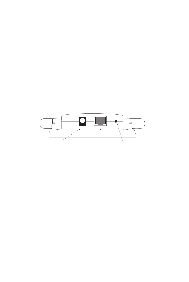
Power Connector
RJ-45 Port
MDI/MDIX Switch
Power LAN
SW

H
ARDWARE
D
ESCRIPTION
4
Applications
EZ Connect wireless products offer a fast, reliable, cost-effective
solution for wireless Ethernet client access to the network in
applications such as:
•Video Game Systems
Provides wireless Internet access for users of video game
systems such as Nintendo GameCube, Microsoft Xbox and
Sony PlayStation II
•Remote access to corporate network information
E-mail, file transfer, and terminal emulation
•Difficult-to-wire environments
Historical or old buildings, asbestos installations, and open
areas where wiring is difficult to employ
•Frequently changing environments
Retailers, manufacturers, and banks which frequently
rearrange the workplace or change locations
•Temporary LANs for special projects or peak periods
Trade shows, exhibitions, and construction sites that need a
temporary setup. Retailers, airline, and shipping companies
that need additional workstations for peak periods. Auditors
who require workgroups at customer sites
•Access to databases for mobile workers
Doctors, nurses, retailers, or white-collar workers who need
access to databases while being mobile in a hospital, retail
store, in an office, or on a campus
•SOHO users
SOHO (Small Office and Home Office) users who need easy
and quick installation of a small computer network
LED I
NDICATORS
5
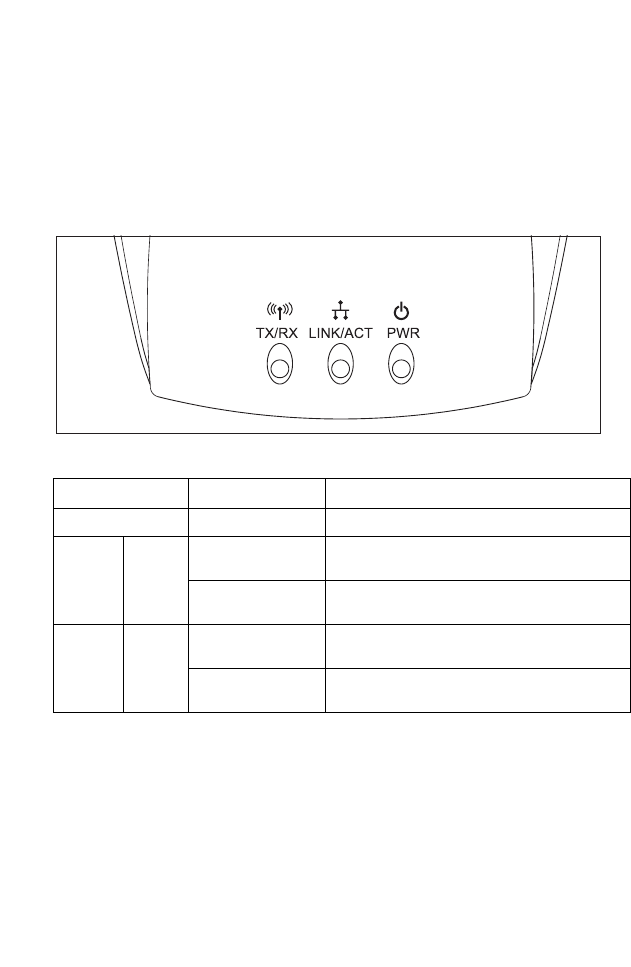
LED Indicators
The EZ Connect 2.4 GHz Wireless Ethernet Adapter includes
three status LED indicators, as described in the following figure
and table.
LED Status Description
Power (PWR) On (Red) Power is being supplied.
Wireless
Link TX/RX Flashing (Green) The device is transmitting data through
wireless links.
Flashing (Green) The device is receiving data through
wireless links.
Ethernet LNK/
ACT On (Yellow) The device has established a valid
Ethernet link.
Flashing (Yellow) The device is transmitting or receiving data
on the Ethernet LAN

H
ARDWARE
D
ESCRIPTION
6
System Requirements
Before you install the EZ Connect 2.4 GHz Wireless Ethernet
Adapter, be sure you have met the following requirements:
•An AC power outlet (100~240 V, 50~60 Hz)
•An available RJ-45 (UTP) port on an Ethernet hub or switch
•802.11b compliant wireless Ethernet adapters with TCP/IP
protocols installed
•TCP/IP network protocol installed on each PC that needs to
access the Internet.
•A Java-enabled web browser, such as Microsoft Internet
Explorer 5.5 or above installed on one PC at your site for
configuring the Wireless Ethernet Adapter.

7
H
ARDWARE
I
NSTALLATION
1. Select the Site – Choose a location for your SMC2671W
Wireless Ethernet Adapter. Usually, the best location is at the
center of your wireless coverage area, if possible within
line-of-sight of all wireless devices.
2. Place the wireless ethernet adapter in a position that gives it
maximum coverage. Normally, the higher you place the
antenna, the better the performance.
3. Position the antennas in the desired positions. For more
effective coverage, position one antenna along the vertical
axis and the other antenna along the horizontal axis (the
antennas emit signals along the toroidal plane - and thus
provide more effective coverage when positioned along
different axis).
4. If used in Ethernet Converter mode, connect the Ethernet
cable to the RJ-45 socket of the device will communicate
wirelessly with an access point.
5. If used in Acces Point, connect the Ethernet cable – The
SMC2671W can be wired to an Ethernet network through an
Ethernet device such as a hub or a switch using category 3, 4,
or 5 UTP Ethernet cable and an RJ-45 connector.
6. Connect the power cable – Connect the power adapter cable
to the 5 VDC power socket on the rear panel.
Warning: Use only the power adapter supplied with the
SMC2671W.

8
S
YSTEM
C
ONFIGURATION
Your SMC2671W is a plug and Play device. This means that, in
most cases, you will not need to configure it.
The SMC2671W Wireless Ethernet Adaptert includes an SNMP
agent that is accessible through an SNMP manager application
(EZ Connect Wireless AP Manager.) The SNMP agent supports
read-write and read-only modes.
The provided CD contains a utility program for the EZ Connect
2.4 GHz Wireless Ethernet Adapter. The latest version may be
downloaded from the download site specified on the back cover
of this manual.
The SMC2671W can be configured by any Java-supported
browser, which is Internet Explorer 5.5 or above. Using the web
management interface, you can configure the Wireless Access
Point and view statistics to monitor network activity.
Before you attempt to log into the SMC2671’s web-based
Administration, please verify the following.
1. Your browser is configured properly (see below).
2. Disable any firewall or security software that may be running.
3. Confirm that you have a good link LED where your computer
is plugged into the Wireless Access Point. If you don’t have a
link light – then try another cable to get a good link.

B
ROWSER
C
ONFIGURATION
9
Browser Configuration
Confirm your browser is configured for a direct connection to the
Internet using the Ethernet cable that is installed in the computer.
This is configured through the options/preference section of your
browser.
Disable Proxy Connection
You will also need to verify that the HTTP Proxy feature of your
web browser is disabled. This is so that your web browser will be
able to view the SMC2671W configuration pages. The following
steps are for Internet Explorer. Determine which browser you use
and follow the appropriate steps.
Internet Explorer (5 or above) in Microsoft Windows
1. Open Internet Explorer. Click Tools, and then select Internet
Options.
2. In the Internet Options window, click the Connections tab.
3. Click the LAN Settings button.
4. Clear all the check boxes and click OK to save these LAN
settings changes.
5. Click OK again to close the Internet Options window.
Internet Explorer in Macintosh
1. Open Internet Explorer. Click Explorer/Preferences.
2. In the Internet Explorer Preferences window, under Network,
select Proxies.
3. Uncheck all check boxes and click OK.

S
YSTEM
C
ONFIGURATION
10
To access the SMC2671W’s
management interface, enter the
Wireless Access Point IP address in
your web browser http://
192.168.2.254 Then click LOGIN.
(By default, there is no password.)
The home page displays the Setup options.
Navigating the Web Browser Interface
The SMC2671W’s management interface features a user-friendly
setup interface. This configuration UI supports advanced
functions like password setting , LAN IP setting, wireless security
configuration and MAC address filtering, SNMP, firmware
upgrade, and other advanced functions.
Making Configuration Changes
Configurable parameters have a dialog box or a drop-down list.
Once a configuration change has been made on a page, be sure
to click the APPLY or REFRESH button at the bottom of the page
to enable the new setting.
Note: To ensure proper screen refresh after a command entry,
ensure that Internet Explorer 5.5 is configured as follows:
Under the menu Tools/Internet Options/General/
Temporary Internet Files/Settings, the setting for “Check
for newer versions of stored pages” should be “Every visit
to the page.”

N
AVIGATING
THE
W
EB
B
ROWSER
I
NTERFACE
11
Use the web management interface to define system parameters,
manage and control the Wireless Access Point and its ports, or
monitor network conditions. The following table outlines the
selections available from this program.
Menu Description
System Sets the password for administrator access, and the IP address
of a PC that will be allowed to manage the Wireless Access Point
remotely
LAN Sets the TCP/IP configuration of the Wireless Access Point’s
LAN interface and all DHCP clients
Wireless Configures the wireless channel, SSID, and encryption for
wireless communications
Filter Configures control access to your network clients based on the
MAC (Media Access Control) Address of the client machine
Tools Contains options to backup & restore the current configuration,
restore all configuration settings to the factory defaults, update
system firmware, or reset the system
Provides WAN connection type and status, firmware and
hardware version numbers, system IP settings, as well as
DHCP, NAT, and Firewall information.
Displays the number of attached clients, the firmware versions,
the physical MAC address for each media interface, and the
hardware version and serial number.
S
YSTEM
C
ONFIGURATION
12
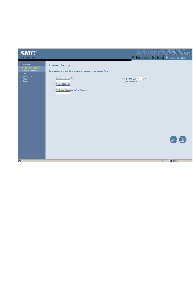
System
Password Settings
Use this menu to restrict access based on a password. By
default, there is no password. For security you should assign one
before exposing the SMC2671W to the Internet.
Passwords can contain from 3–12 alphanumeric characters and
are not case sensitive.
Enter a maximum Idle Time Out (in minutes) to define a
maximum period of time for which the login session is maintained
during inactivity. If the connection is inactive for longer than the
maximum idle time, it will perform system logout, and you have to
login to the web management system again. (Default:
10 minutes)
N
AVIGATING
THE
W
EB
B
ROWSER
I
NTERFACE
13
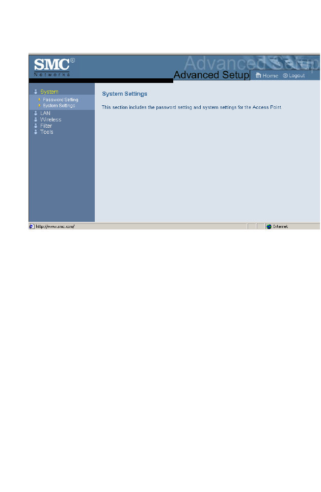
System Settings
System Settings allows a remote PC to configure, manage, and
monitor the SMC2671W using a standard web browser. Check
Enable and enter the IP address of the remote host. Click APPLY.
Note: If you specify 0.0.0.0 as this IP address, any host can
manage the SMC2671W.
S
YSTEM
C
ONFIGURATION
14
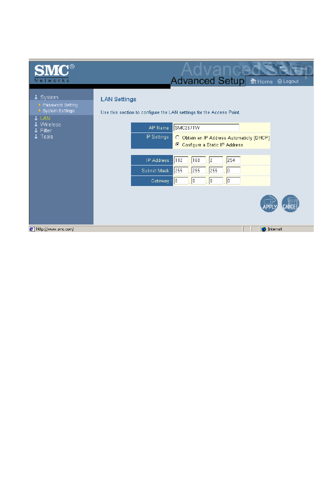
LAN
With Obtain an IP Address Automaticly [DHCP] enabled, the IP
address, subnet mask and default gateway can be dynamically
assigned to the SMC2671W by the network DHCP server.
(Default: Disable)
Note: If there is no DHCP server on your network, then the
SMC2671W will automatically start up with its default IP
address, 192.168.2.254.
By using the SMC2671W’s built-in DHCP (Dynamic Host
Configuration Protocol) server, you are allowing the SMC2671W
to handle all the IP addressing on your Local Area Network (LAN)
(when in Access Point mode). This can save you much of the time
and hassle of setting up your network. If you have a server on
your network that requires a static IP address, you may still use
the “DHCP Server” and manually assign a static IP address to
your server. (Default: Disable)
N
AVIGATING
THE
W
EB
B
ROWSER
I
NTERFACE
15
If your Internet Service Provider has assigned a fixed IP address,
select Configure a Static IP Address. Enter the assigned address
and subnet mask for the SMC2671W then enter the gateway
address of your ISP.
You may need a fixed address if you want to provide Internet
services, such as a web server or FTP server.
Wireless
To configure the SMC2671W as an Ethernet Converter, all you
need to do is define the radio channel, the Service Set identifier
(SSID), and encryption options.
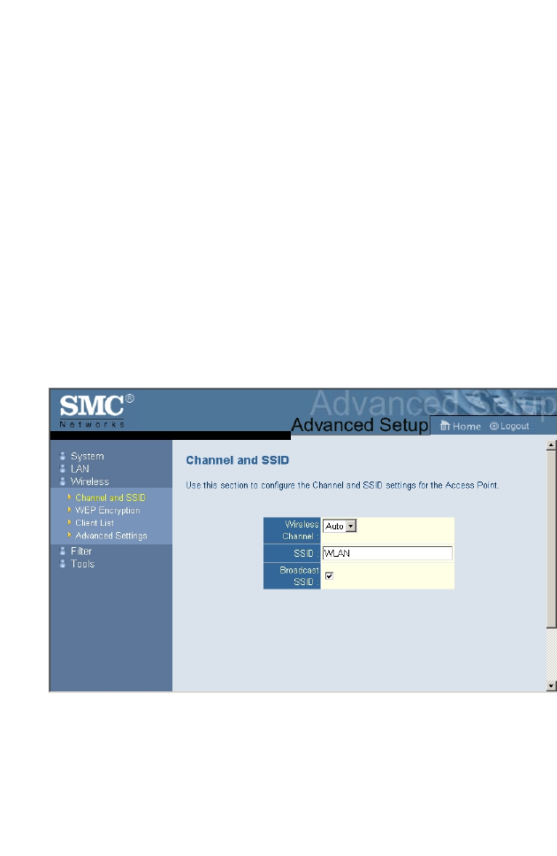
Channel and SSID
If the SMC2671W is in Access Point mode you must specify a
common radio channel and SSID (Service Set ID) to be used by
the Wireless Access Point and all of your wireless clients. Be sure
you configure all of your clients to the same values.
In Ethernet Converter or Repeater mode, the radio channel and
S
YSTEM
C
ONFIGURATION
16
SSID (Service Set ID) of the SMC2671W must be set to the same
values as those of the access point they are associated with.
Wireless Channel: The radio channel through which a wireless
access point communicates with PCs in its BSS. (Default: 7)
Note: The available channel settings are limited by local
regulations.
SSID: The Service Set ID. This should be set to the same value
as other wireless devices in your network. (Default: WLAN.)
Note: The SSID is case sensitive and can consist of up to 32
alphanumeric characters.
Broadcast SSID: In Access Point or Repeater Mode, the
SMC2671W can be enabled to broadcast the SSID on the
wireless network for easy connection with client PCs.
(Default: Enable)
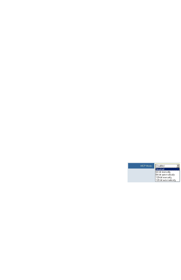
WEP Encryption
If you are transmitting sensitive data
across wireless channels, you should
enable Wired Equivalent Privacy (WEP)
encryption.
Encryption requires you to use the same set of encryption/
decryption keys for a wireless access point and all of its wireless
clients. The SMC2571W supports shared key encryption with key
lengths of the standard 64-bit and industry standard 128-bit. The
bit key must be in hexadecimal numerals.
(0~9, A~F, e.g., D7 0A 9C 7F E5.)
N
AVIGATING
THE
W
EB
B
ROWSER
I
NTERFACE
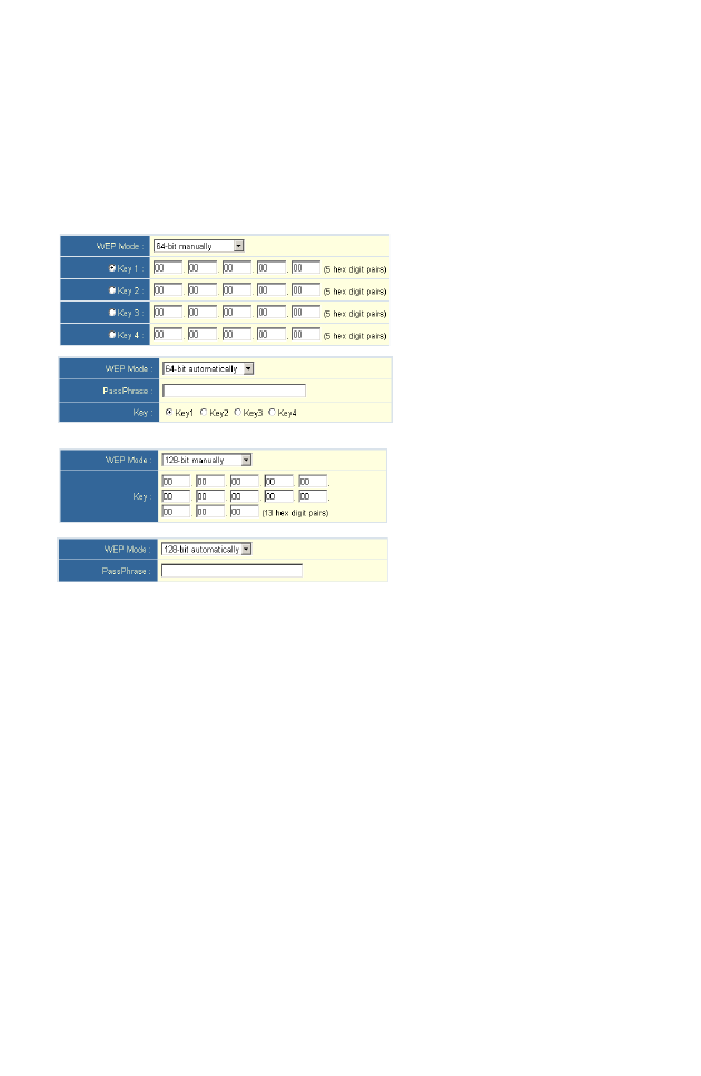
17
64-Bit Manual Entry
Key 1~4 - Each Key ID contains 10 HEX digits.
128-Bit Manual Entry
Key ID contains 26 HEX digits.
You may automatically generate encryption keys or manually
enter the keys. For automatic 64-bit security, enter a passphrase.
Four keys will be generated (as shown above). Choose a key
from the four generated keys. Automatic 128-bit security
generates a single passphrase.
Note that Wired Equivalent Privacy (WEP) protects data
transmitted between wireless nodes, but does not protect any
transmissions over your wired network or over the Internet.
S
YSTEM
C
ONFIGURATION
18
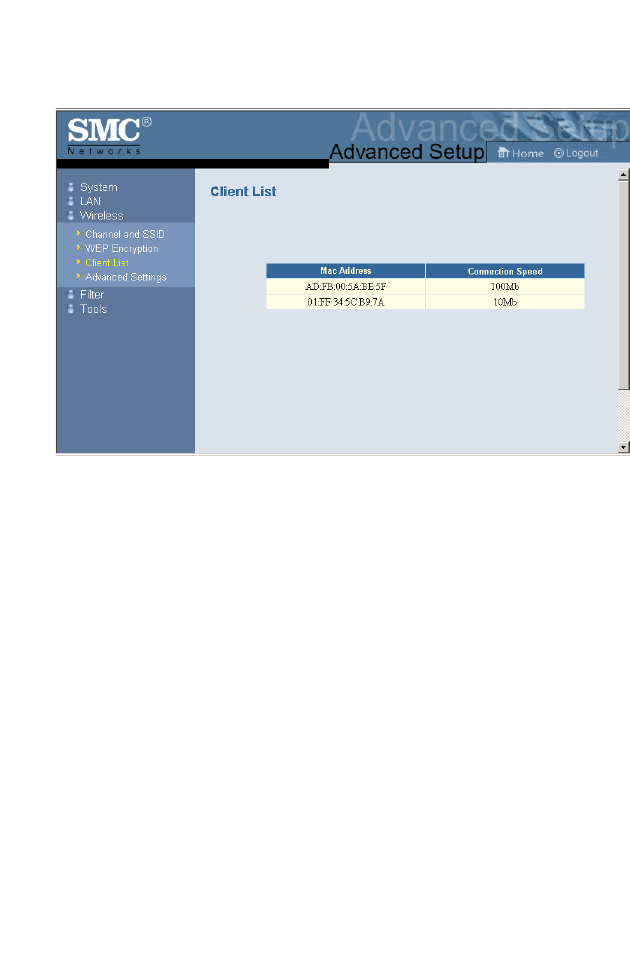
Client List
The Client List screen displays the MAC address and network
speed of the accociated clients. Note that the client list will be
blank if the SMC2671W is in Ethernet Converter mode.