Accton Technology WA3101ACC WLAN Access Point User Manual Part 2
Accton Technology Corp WLAN Access Point Part 2
Contents
- 1. User Manual Part 1
- 2. User Manual Part 2
User Manual Part 2
Setup & Installation 11
Chapter 2
4/3/03 Accton Draft—CONFIDENTIAL
When prompted, log in to the Aruba WLAN Switch as the administrator:
user: admin
password: <administrator password (not displayed)>
This will present you with the Aruba WLAN Switch SOE console prompt (soe>).
Specify the physical Aruba WLAN Switch port to which the new Aruba 50 is con-
nected:
soe> connect <slot number>/<port number>
This will present you with the Aruba 50 console prompt (#). Once connected to the console,
follow the instruction on page 12 to configure Aruba 50.
Direct Terminal Connection
Use this procedure when connecting the Aruba 50 through the LAN or to a non-SPOE net-
work port on the Aruba WLAN Switch. Under these topologies, a direct terminal connection
is required for initial setup.
NOTE—If connecting the Aruba 50 directly to a SPOE network port on the Aruba WLAN
Switch, see the instructions on page 10.
Set up your local terminal.
This procedure requires a terminal or computer running terminal emulation software with the
following settings:
Connect the terminal directly to the Aruba 50.
Use a standard serial cable to connect the Aruba 50 console port to a serial port on your termi-
nal (see Appendix B for port specification).
Establish console communication.
Press <Enter> a few times to establish communication between the terminal and the
Aruba 50. You will be presented the Aruba 50 console prompt (#).
Once connected to the Aruba 50 console, follow the instruction on page 12 to configure the
device.
TABLE 2-1 Console Terminal Settings
Baud Rate Data Bits Parity Stop Bits Flow Control
9600 8 None 1 None
4
5
1
2
3
4/3/03 Accton Draft—CONFIDENTIAL
12 Aruba 50 Part 0500007A
Installation Guide May 2003
Configure the Aruba 50
From the Aruba 50 console, access the boot prompt.
Reboot the Aruba 50 and then immediately (within three seconds as the device is booting)
press any key to interrupt the process:
# boot
<Any key (while booting)>
This will present you with the Aruba 50 boot prompt (apboot>).
Set the intended location for the Aruba 50:
apboot> setenv location <building number>.<floor number>.<device number>
If you performed the recommended site survey using the Aruba WLAN Switch’s built-in
planning tools, the location data for all access points and air monitors can be found on the
tool’s deployment screen (see the Aruba AirOS Software Guide).
If you plan to manually generate the location data, record the following information for each
access point and air monitor. It will be required when configuring the Aruba WLAN Switch.
Building Number A unique number (1-255) is required for each building in your campus.
Floor Number Within any building, a unique number (1-255) is required for each floor.
Device Number Within any floor, a unique number (1-65536) is required for each access
point or air monitor.
Device Description Note the intended function of the device (access point or dedicated air
monitor) and a brief description of its service location.
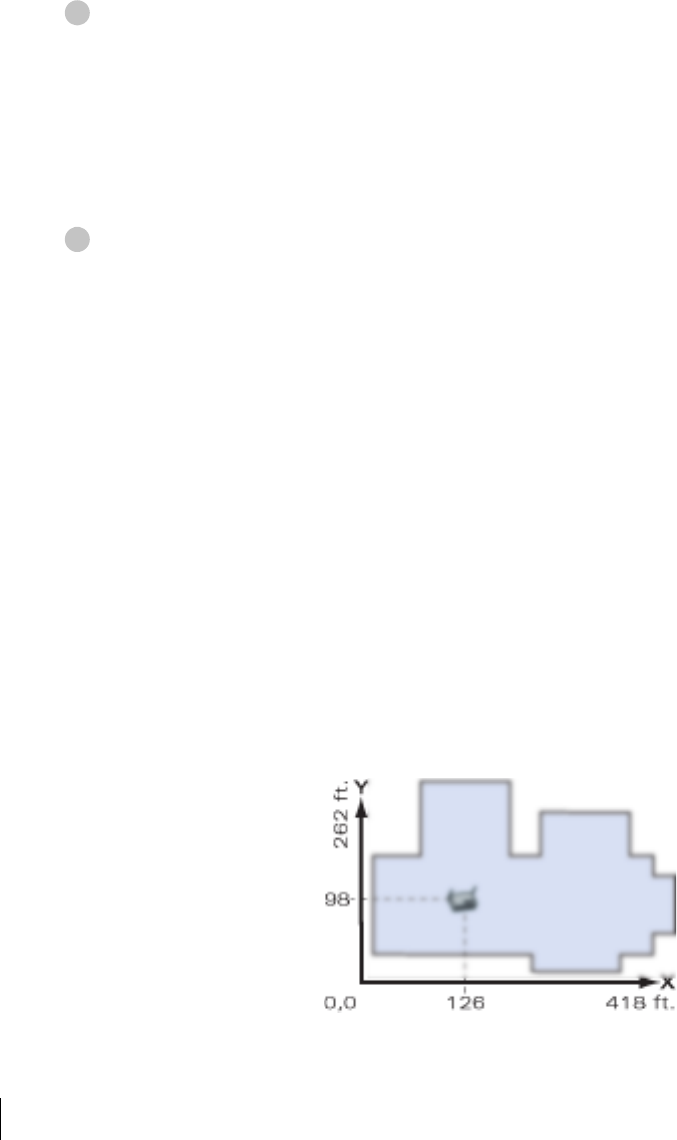
X, Y Coordinates For each access point and air monitor, measure its X and Y position (in
feet) relative to the bottom-left corner of the building plan as seen from
overhead. For example:
Use the same fixed point and orientation for all floors in a building.
1
2

Setup & Installation 13
Chapter 2
4/3/03 Accton Draft—CONFIDENTIAL
Specify host information, if necessary.
The Aruba 50 uses the default host name aruba-master to find the host Aruba WLAN
Switch. This assumes that your DNS has been configured to resolve aruba-master to the
master Aruba WLAN Switch IP address.
zIf you are not using DNS, you must manually configure the Aruba 50 with the IP address
of the master Aruba WLAN Switch:
apboot> setenv serverip <switch IP address>
zIf you are using DNS but wish to specify a different host name, use the following com-
mands:
apboot> setenv master <switch host name>
apboot> setenv serverip <switch host name>
Save the configuration and reboot the Aruba 50.
apboot> save
apboot> boot
Once the Aruba 50 boots, disconnect it and mount it in its intended service location (see
instructions on page 14).
3
4
4/3/03 Accton Draft—CONFIDENTIAL
14 Aruba 50 Part 0500007A
Installation Guide May 2003
Mount the Aruba 50
When initial setup is complete, mount the Aruba 50 in its intended service location.
Select a location as close as possible to the center of the intended coverage area. If necessary,
use the Aruba WLAN Switch’s built-in site survey software to determine the optimum loca-
tions for your access points and air monitors (see your Aruba AirOS Software Guide).
The service location should be free from obstructions or obvious sources of interference. Nor-
mally, the higher you place an access point or air monitor, the better its performance.
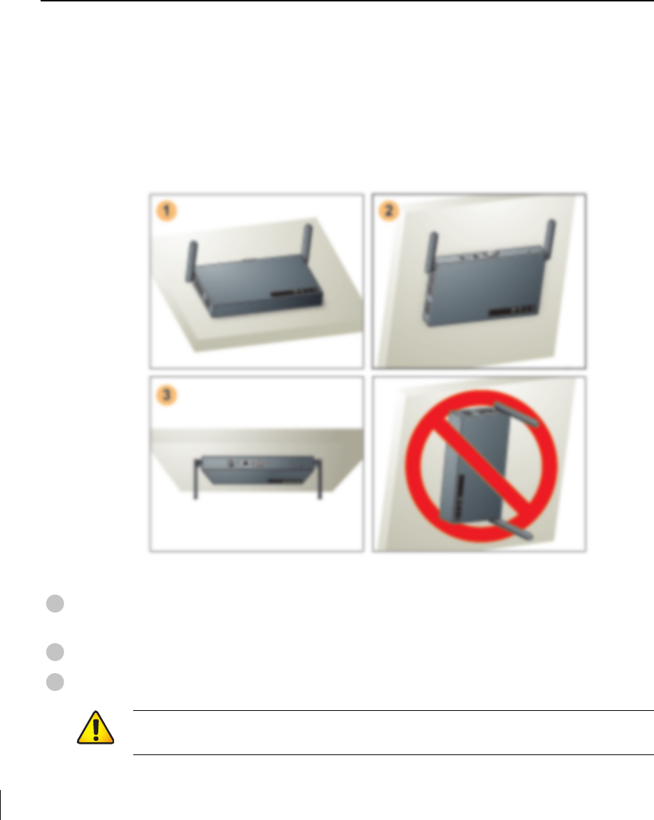
The Aruba 50 can be mounted in the following ways:
FIGURE 2-2 Aruba 50 Mounting Options
Flat on a table or shelf (with the LEDs on top) either free-standing or using the
included mounting kit
Upright on a wall (with the port connectors on top) using the included mounting kit
Suspended from above (with the LEDs on bottom) using the included mounting kit
1
2
3
CAUTION—For safety purposes, do not mount the Aruba 50 sideways (with the air
vents on top and bottom).
Setup & Installation 15
Chapter 2
4/3/03 Accton Draft—CONFIDENTIAL
Free-Standing Placement
To place the Aruba 50 on a flat table or shelf, first attach the included non-skid foot-pads to
the bottom of the chassis.
Using the Mounting Kit
Use the included mounting kit to attach the Aruba 50 to a wall, shelf, or ceiling.
NOTE—Do not attach the rubber foot-pads to the Aruba 50 when using the mounting kit.
Attach the mounting cradle to a solid mounting surface.
Place the flat side of the cradle against the mounting surface. If attaching the cradle to a wall,
orient it so that the cable tie anchors are positioned at the top. If attaching the cradle to a table,
shelf, or ceiling, orient the cable tie anchors toward the cable route.
CAUTION—Do not place the Aruba 50 in any place where it could fall on people or
equipment. For more secure installation, use the included mounting kit.
1
4/3/03 Accton Draft—CONFIDENTIAL
16 Aruba 50 Part 0500007A
Installation Guide May 2003
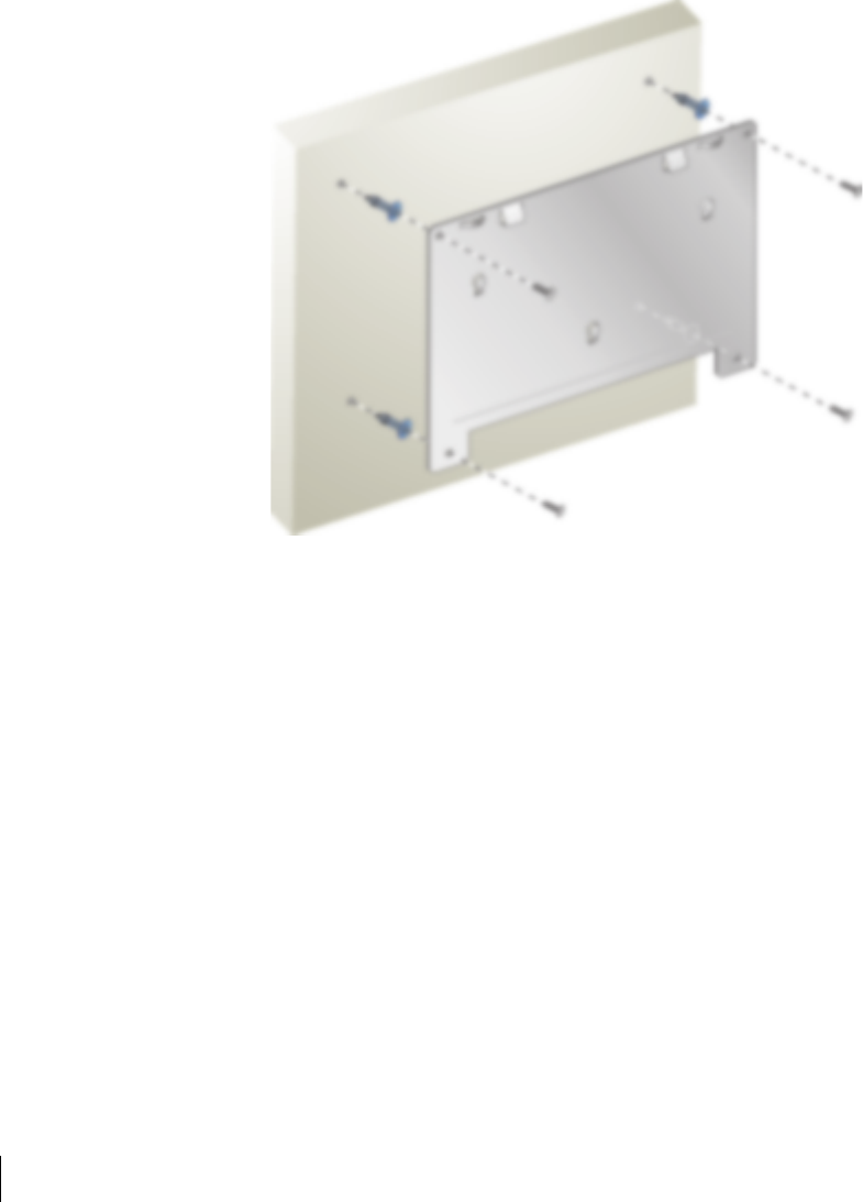
Use the four included #6 screws (or equivalent) to secure the mounting cradle. If attaching the
cradle to drywall, we recommend using appropriate wall anchors (not included) as show in
Figure 2-3:
FIGURE 2-3 Attaching the Mounting Cradle
Setup & Installation 17
Chapter 2
4/3/03 Accton Draft—CONFIDENTIAL
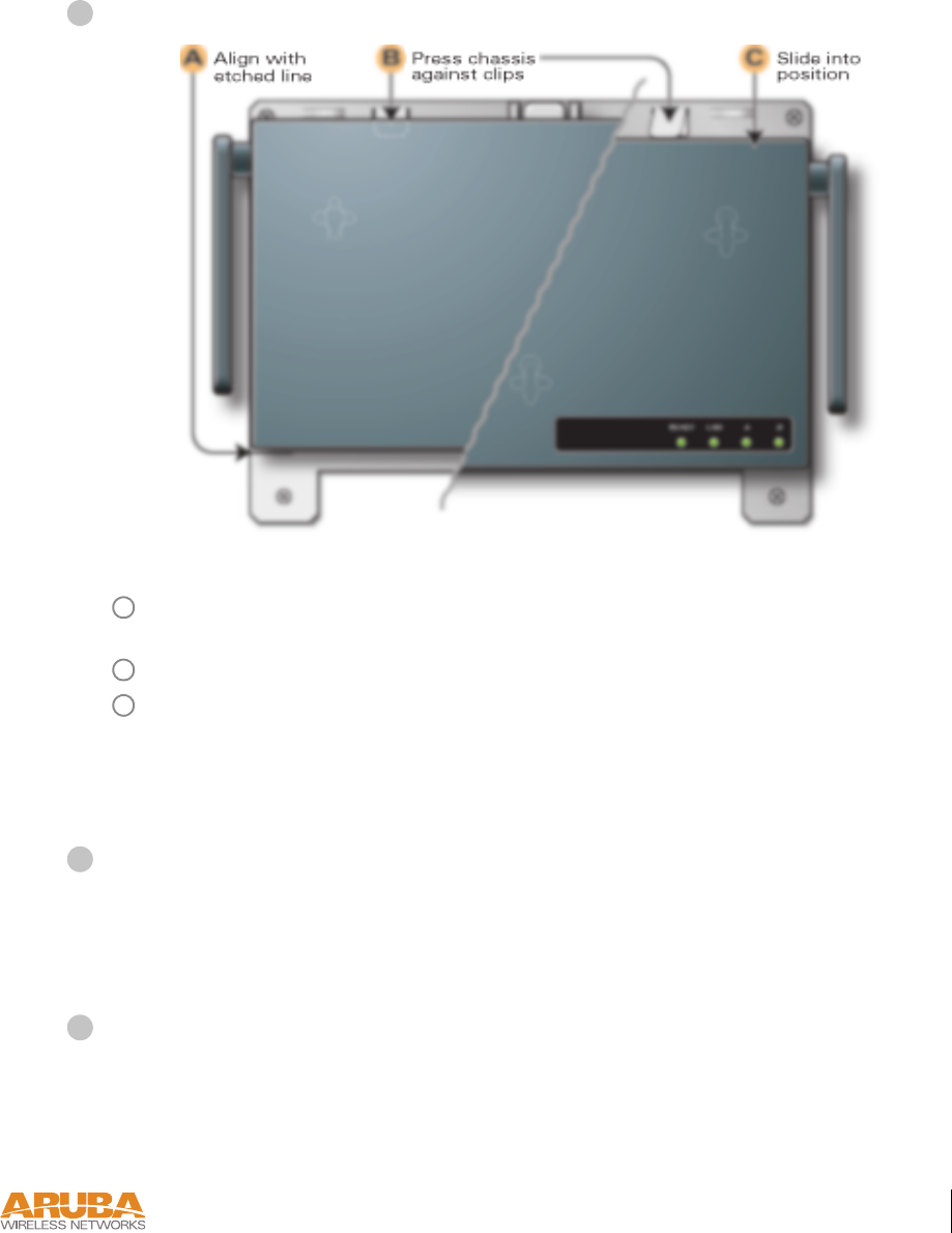
Place the Aruba 50 into the mounting cradle as shown in Figure 2-4.
FIGURE 2-4 Placing the Aruba 50 into the Cradle
Align the front edge of the chassis with the etched line on the mounting cradle. This will
fit the Aruba 50 mounting slots over the matching cradle posts.
Press and hold the Aruba 50 chassis against the retaining clips on the cradle.
Slide the Aruba 50 into place. When properly positioned, the retaining clips will spring
up to hold the chassis firmly in place.
NOTE—To remove the Aruba 50 from the cradle, press down on both retaining clips and
slide the chassis free of the mounting posts.
Secure the Aruba 50, if desired.
To prevent the unauthorized removal of the Aruba 50 from its installed location, use a Kens-
ington MicroSaver Security Cable (not included). Wrap the security cable around an immov-
able object, insert the cable’s lock into the Kensington Security Slot on the back of the
Aruba 50, and turn the key.
Orient the antennas.
For best performance, swivel the antennas so that they are oriented vertically (see Figure 2-2
on page 14).
Once mounting is complete, connect the required cables (see instructions on page 18).
2
A
B
C
3
4

4/3/03 Accton Draft—CONFIDENTIAL
18 Aruba 50 Part 0500007A
Installation Guide May 2003
Connect Required Cables
The cables required for operating the Aruba 50 depend on your intended network topology
(see Figure 2-1 on page 8) and on the physical location.
Direct SPOE to the Aruba WLAN Switch
Use this procedure when connecting the Aruba 50 directly to an SPOE-compatible network
port on the Aruba WLAN Switch (see “Power Over Ethernet” on page 2). SPOE provides
10/100 Mbps Ethernet, serial connection, and power over one cable.
NOTE—If connecting the Aruba 50 through the LAN or to a non-SPOE network port on
the Aruba WLAN Switch, see the instructions on page 19.
Connect the included SPOE adapter to the Aruba 50.
Connect the adapter’s 9-pin serial connector to the Console port on the back of the
Aruba 50.
Connect the adapter’s male RJ-45 plug to the FE port on the back of the Aruba 50.
Connect the Aruba 50 to the Aruba WLAN Switch.
The connection between the Aruba 50 and the Aruba WLAN Switch requires an 8-conduc-
tor, Category 5 UTP, straight-through FE cable with RJ-45 connectors (see Appendix B for
port specifications).
Any FE cable installed in an air-handling space, as described in NEC (2002) Article 300.22(C),
should be suitable under NEC Article 800.50 and marked accordingly for use in plenums and
air-handling spaces with regard to smoke propagation, such as CL2-P, CL3-P, MPP or CMP.
Install cables in accordance with all applicable local regulations and practices.
Connect one end of the FE cable directly to the RJ-45 socket on the SPOE adapter that
was attached to the Aruba 50 in the previous step.
Connect the other end of the FE cable directly to an available SPOE network port on the
Aruba WLAN Switch.
NOTE—The Aruba 50 must be connected to the Aruba WLAN Switch without any inter-
vening hubs, routers, or other networking equipment.
1
A
B
2
A
B
Setup & Installation 19
Chapter 2
4/3/03 Accton Draft—CONFIDENTIAL
LAN or POE Connection
Use this procedure when connecting the Aruba 50 through the LAN or to a non-SPOE net-
work port on theAruba WLAN Switch.
NOTE—If connecting the Aruba 50 directly to a SPOE network port on the Aruba WLAN
Switch, see the instructions on page 18.
Connect the Aruba 50 to the network.
Connect one end of an FE cable to a network hub, router, or switch that has a routable
path to the Aruba WLAN Switch.
zIf the connecting device supports POE (see “Power Over Ethernet” on page 2), use an
8- or 4-conductor, Category 5 UTP, straight-through FE cable.
zIf the connecting device does not support POE, use a 4- or 8-conductor, Category 5
UTP, straight-through or crossover FE cable.
Any FE cable installed in an air-handling space, as described in NEC (2002) Article
300.22(C), should be suitable under NEC Article 800.50 and marked for use in plenums
and air-handling spaces with regard to smoke propagation, such as CL2-P, CL3-P, MPP
or CMP. Install cables in accordance with all applicable local regulations and practices.
For port and cable details, see Appendix B.
Connect the other end of the FE cable to the FE port on the back of the Aruba 50.
Connect power.
The Aruba 50 can receive electrical power using the following options:
zPOE–If connecting the Aruba 50 to a device that supplies IEEE 802.3af compliant POE
(see “Power Over Ethernet” on page 2), no additional power connection is necessary.
zPower Outlet
NOTE—When the Aruba 50 is installed in an air-handling space, as described in NEC
(2002) Article 300.22(C), POE must be used instead of a power outlet.
If local regulations and practices permit, connect the included AC power adapter cable to
the DC power socket on the rear panel of the Aruba 50 and plug it into an appropriate
power outlet.
CAUTION—Use only the AC power adapter supplied with this device. Other-
wise, the product may be damaged.
1
A
B
2

4/3/03 Accton Draft—CONFIDENTIAL
20 Aruba 50 Part 0500007A
Installation Guide May 2003

Troubleshooting 21
Appendix A
4/1/03 Accton Draft—CONFIDENTIAL
APPENDIX A
Troubleshooting
*Information Pending

4/1/03 Accton Draft—CONFIDENTIAL
22 Aruba 50 Part 0500007A
Installation Guide May 2003
Port Specifications 23
Appendix B
4/1/03 Accton Draft—CONFIDENTIAL
APPENDIX B
Port Specifications
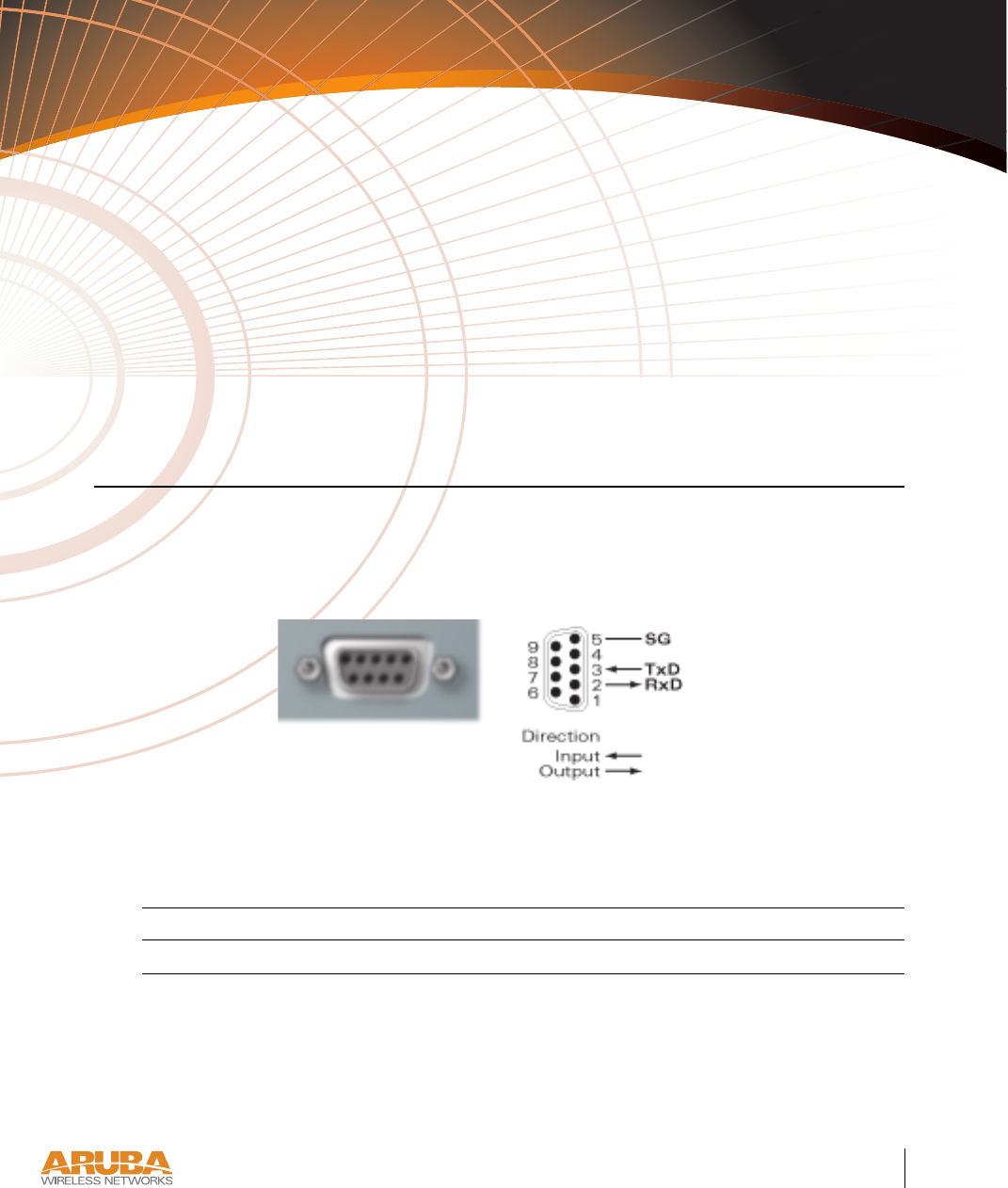
Console Port
The console port is located on the back of the Aruba 50 and has a DB-9 female connector. Port
pin-outs are shown in Figure B-1:
Figure B-1 Aruba 50 Console Port
Communication settings for the console port are specified in Table B-1 :
Tab l e B - 1 Console Terminal Settings
Baud Rate Data Bits Parity Stop Bits Flow Control
9600 8 None 1 None
Aruba 50
Console
DB-9 Female
DCE Pin-Out
4/1/03 Accton Draft—CONFIDENTIAL
24 Aruba 50 Part 0500007A
Installation Guide May 2003
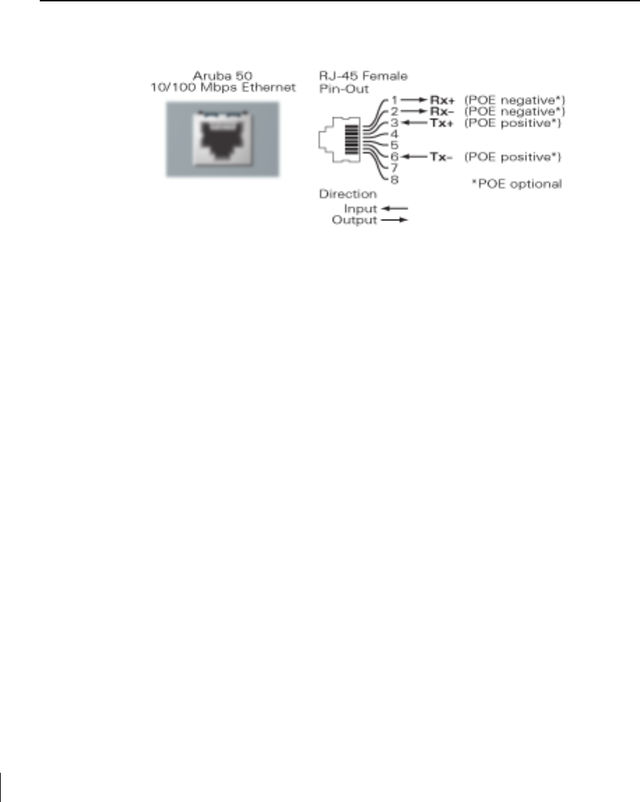
FE Port
The 10/100 Mbps Ethernet (FE) port is located on the back of the Aruba 50 and has an RJ-45
female connector. Port pin-outs are shown in Figure B-2:
Figure B-2 Aruba 50 FE Port
The port accepts a 4- or 8-conductor Category 5 UTP FE cable with an RJ-45 male connector.
The FE port detects MDI/MDX and automatically adjusts for straight-through or crossover
cables. However, if Power Over Ethernet (POE) is used, a straight-through cable is required.
The maximum length for FE cables is 100 meters (325 feet).
When the Aruba 50 is installed in an air-handling space, as described in NEC (2002) Article
300.22(C), POE is required. Also, any FE cable installed in such spaces should be suitable
under NEC Article 800.50 and marked accordingly for use in plenums and air-handling spaces
with regard to smoke propagation, such as CL2-P, CL3-P, MPP or CMP.
Install cables in accordance with all applicable local regulations and practices.
Port Specifications 25
Appendix B
4/1/03 Accton Draft—CONFIDENTIAL
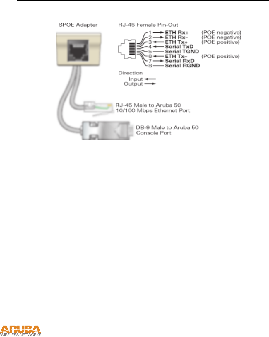
SPOE Adapter
The Serial & Power Over Ethernet (SPOE) adapter pin-outs are shown in Figure B-3:
Figure B-3 Aruba SPOE Adapter
The adapter requires an 8-conductor Category 5 UTP, straight-through FE cable with RJ-45
male connectors. The cable must connect the SPOE adapter to an FE+SPOE port on the
Aruba WLAN Switch, with no intervening hubs, routers, or other network equipment.
The maximum length for FE cables is 100 meters (325 feet).
The Aruba 50 and SPOE adapter are plenum rated. When is installed in an air-handling space,
as described in NEC (2002) Article 300.22(C), the connecting FE cable should be suitable
under NEC Article 800.50 and marked accordingly for use in plenums and air-handling spaces
with regard to smoke propagation, such as CL2-P, CL3-P, MPP or CMP.
Install cables in accordance with all applicable local regulations and practices.

4/1/03 Accton Draft—CONFIDENTIAL
26 Aruba 50 Part 0500007A
Installation Guide May 2003

Product Specifications 27
Appendix C
4/1/03 Accton Draft—CONFIDENTIAL
APPENDIX C
Product Specifications
The following specifications apply to the Aruba 50 Wireless Access Point (model WAP-50).
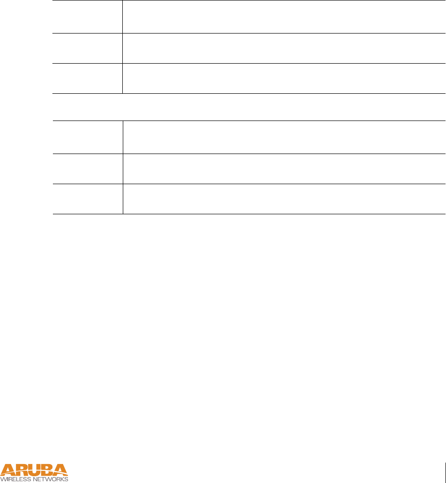
Physical
Environment
TABLE C-1 Physical Specifications
Item Measurement
Size 20.5 x 13.6 x 4 cm
(8.07 x 5.35 x 1.58 in)
Weight 280 gram (9.9 oz.)
TABLE C-2 Environmental Specifications
Item Measurement
Temperature Operating: 0 to 50 ºC (32 to 122 ºF)
Storage: 0 to 70 ºC (32 to 158 ºF)
Humidity 5% to 95% (non-condensing)

4/1/03 Accton Draft—CONFIDENTIAL
28 Aruba 50 Part 0500007A
Installation Guide May 2003
Operation
General
TABLE C-3 Operational Specifications
Item Measurement
Maximum Channels 802.11a—US & Canada: 13, Japan: 5
802.11b—US & Canada: 1-11, Europe: 1-13, France: 10-13,
Japan: 1-14, Spain: 10-11
Maximum Clients 64
Operating Range 802.11a—Up to 503 m (1650 ft.)
802.11b—Up to 396 m (1300 ft.)
Data Rate 802.11a—6, 9, 12, 18, 24, 36, 48, 54 Mbps per channel
802.11b—1, 2, 5.5, 11 Mbps per channel
Operating Frequency 802.11a—
5.15 ~ 5.25 GHz (lower band) US/Canada, Japan
5.25 ~ 5.35 GHz (middle band) US/Canada
5.725 ~ 5.825 GHz (upper band) US/Canada
802.11b—
2.412 ~ 2.452 GHz US/Canada, Japan
2.457 ~ 2.462 GHz US/Canada, Europe, France, Japan, Spain
2.467 ~ 2.472 GHz Europe, France, Japan
2.484 GHz Japan
Output Power 16 dBm minimum
Power Adapter Input—
100-240 AC, 50-60 Hz
Access Point Input—
3.3 VDC, 3 A (AC adapter), or
48 VDC, 150 mA (POE)
LED Indicators Ready (Power), LAN (Ethernet Link/Activity), .A and .B (Access
Point/Air Monitor Mode)
Standards IEEE 802.3 10Base-T, IEEE 802.3u 100Base-TX,
IEEE 802.11a/b, IEEE 802.3af
802.11b—
2.412 ~ 2.452 GHz US/Canada, Japan
2.457 ~ 2.462 GHz US/Canada, Europe, France, Japan, Spain
2.467 ~ 2.472 GHz Europe, France, Japan
2.484 GHz Japan
15
. IEEE 802.3af
Product Specifications 29
Appendix C
4/1/03 Accton Draft—CONFIDENTIAL
Maximum Distance
Maximum distances posted below are the actual tested distance thresholds. However, there are
many variables such as barrier composition and construction and local environmental interfer-
ence that may impact your actual distances and cause you to experience distance thresholds far
lower than those we post below:
An Outdoor Environment is a line-of-sight environment with no interference or obstruction
between the access point and clients.
An Indoor Environment is a typical office or home environment with floor to ceiling obstruc-
tions between the access point and clients.
TABLE C-4 IEEE 802.11a Maximum Distances
Speed (Mbps)
Condition544836241812 9 6
Outdoor
Environment
40 m
(132 ft.)
221 m
(726 ft.)
251 m
(825 ft.)
322 m
(1056 ft.)
350 m
(1155 ft.)
382 m
(1254 ft.)
453 m
(1485 ft.)
503 m
(1650 ft.)
Indoor
Environment
18 m
(60 ft.)
25 m
(82 ft.)
30 m
(99 ft.)
35 m
(115 ft.)
40 m
(132 ft.)
45 m
(149 ft.)
48 m
(157 ft.)
50 m
(165 ft.)
TABLE C-5 IEEE 802.11b Maximum Distances
Speed (Mbps)
Condition 11 5.5 2 1
Outdoor
Environment
152 m
(500 ft.)
233 m
(766 ft.)
315 m
(1033 ft.)
396 m
(1300 ft.)
Indoor
Environment
23 m
(75 ft.)
30 m
(100 ft.)
61 m
(200 ft.)
61 m
(200 ft.)
IEEE 802.11b Maximum Distances
152 m
(500 ft.)
233 m
(766 ft.)
315 m
(1033 ft.)
396 m
(1300 ft.)
Speed (Mbps)
11
5.5
2
1
23 m
(75 ft.)
30 m
(100 ft.)
61 m
(200 ft.)
61 m
(200 ft.)
An Outdoor Environment is a line-of-sight environment with no interference or obstruction
between the access point and clients.
An Indoor Environment is a typical office or home environment with floor to ceiling obstructions
between the access point and clients.

4/1/03 Accton Draft—CONFIDENTIAL
30 Aruba 50 Part 0500007A
Installation Guide May 2003
Sensitivity and Modulation
TABLE C-6 IEEE 802.11a Sensitivity and Modulation
Modulation/Rates Sensitivity
(dBm)
5.15-5.25GHZ
(dBm)
5.25-5.35GHZ
(dBm)
BPSK (6 Mbps) -85 16 20
BPSK (9 Mbps) -84 16 20
QPSK (12 Mbps) -83 16 19
QPSK (18 Mbps) -81 16 19
16 QAM (24 Mbps) -78 16 18
16 QAM (36 Mbps) -74 16 18
64 QAM (48 Mbps) -69 16 16
64 QAM(54 Mbps) -65 14 14
TABLE C-7 IEEE 802.11b Sensitivity and Modulation
Modulation/Rates Sensitivity
(dBm)
2.412-2.484GHZ
(dBm)
DBPSK (1 Mbps) -86 20
DQPSK (2 Mbps) -85 17
PBCC (5.5 Mbps) -85 15
CCK (5.5 Mbps) -81 13
PBCC (11 Mbps) -83 7
CCK (11 Mbps) -81 0
IEEE 802.11b Sensitivity and Modulation
2.412-2.484GHZ
DBPSK (1 Mbps)
-86 20
DQPSK (2 Mbps)
PBCC (5.5 Mbps)
CCK (5.5 Mbps)
PBCC (11 Mbps)
CCK (11 Mbps)
-86
-85
-85
-81
-83
-81
20
17
15
13
7
0
C-5

Product Specifications 31
Appendix C
4/1/03 Accton Draft—CONFIDENTIAL
Certifications
TABLE C-8 Certifications
Item Measurement
Electromagnetic
Compatibility
FCC Part 15 Class B, FCC Part 15 Class C 15.207/15.247,
FCC Part 15 Class E 15.407
ICES-003,
RSS 210 (CAN)
IEC 61000-4-2/3/4/6/11
EN 55022, EN55024 (89/336/EEC),
ETS 300 328 (89/336/EEC), ETS 301 489 (89/336/EEC),
ETS 301 893
AS/NZS 3548,
RFS 29 (NZ)
Safety CSA/NTRL (CSA 22.2 No. 950 & UL 1950)
EN60950 (TÜV/GS), IEC60950 (CB), UL 2043
C-6