Accton Technology WA6101ACC WLAN Access Point 2220 User Manual AccessPointUG
Accton Technology Corp WLAN Access Point 2220 AccessPointUG
UserManual.wiki
>
Accton Technology
>
WA6101ACC User Manual
Manual
Navigation menu
Upload a User Manual
Namespaces
Wiki Guide
HTML
PDF
Info
Views
User Manual
Discussion / Help
Navigation
![[Final Draft—Nortel Confidential]Part No. 214853-AApril 20034655 Great America ParkwaySanta Clara, CA 95054Using the Nortel NetworksWireless LAN Access Point2220AccessPointUG.book Page 1 Thursday, February 27, 2003 12:22 PM](https://usermanual.wiki/Accton-Technology/WA6101ACC/User-Guide-312417-Page-1.png)
![2214853-A[Final Draft—Nortel Confidential]Copyright StatementNo part of this publication may be reproduced, stored in a retrieval system, or transmitted in any form or by any means,whether electronic, mechanical, photocopying, recording or otherwise without the prior writing of the publisher.Windows 98SE/2000/ME/XP are trademarks of Microsoft Corp.Pentium is trademark of Intel.Nortel Networks and the Nortel Networks logo are trademarks of Nortel Networks, Inc.All copyright reserved.CompliancesFederal Communication Commission Interference StatementThis equipment has been tested and found to comply with the limits for a Class B digital device, pursuant to Part 15 ofthe FCC Rules. These limits are designed to provide reasonable protection against harmful interference in a residentialinstallation. This equipment generates, uses and can radiate radio frequency energy and, if not installed and used inaccordance with instructions, may cause harmful and, if not installed and used in accordance with instructions, maycause harmful interference to radio communications. However, there is no guarantee that the interference will not occurin a particular installation. If this equipment does cause harmful interference to radio or television reception, which canbe determined by turning the equipment off and on, the user is encouraged to try to correct the interference by one ormore of the following measures:• Reorient the receiving antenna• Increase the separation between the equipment and receiver• Connect the equipment into an outlet on a circuit different from that to which the receiver is connected• Consult the dealer or an experienced radio/TV technician for helpFCC Caution: To assure continued compliance, (example - use only shielded interface cables when connecting tocomputer or peripheral devices). Any changes or modifications not expressly approved by the party responsible forcompliance could void the user’s authority to operate this equipment.This device complies with Part 15 of the FCC Rules. Operation is subject to the following two conditions: (1) Thisdevice may not cause harmful interference, and (2) this device must accept any interference received, includinginterference that may cause undesired operation.CAUTION STATEMENT:FCC Radiation Exposure StatementFCC RF Radiation Exposure StatementThis equipment complies with FCC RF radiation exposure limits set forth for an uncontrolled environment. Thisequipment should be installed and operated with a minimum distance of 20 centimeters (8 inches) between the radiatorand your body. This transmitter must not be co-located or operating in conjunction with any other antenna or transmitter.Industry Canada - Class BThis digital apparatus does not exceed the Class B limits for radio noise emissions from digital apparatus as set out in theinterference-causing equipment standard entitled “Digital Apparatus,” ICES-003 of the Department of Communications.AccessPointUG.book Page 2 Thursday, February 27, 2003 12:22 PM this device is going to be operated in 5.15 ~5.25GHz frequency range, it is restricted in indoor environment only.](https://usermanual.wiki/Accton-Technology/WA6101ACC/User-Guide-312417-Page-2.png)
![3Using the Nortel Networks Wireless LAN Access Point 2220[Final Draft—Nortel Confidential]Cet appareil numérique respecte les limites de bruits radioélectriques applicables aux appareils numériques de Classe Bprescrites dans la norme sur le matériel brouilleur: “Appareils Numériques,” NMB-003 édictée par le ministère desCommunications.AccessPointUG.book Page 3 Thursday, February 27, 2003 12:22 PM](https://usermanual.wiki/Accton-Technology/WA6101ACC/User-Guide-312417-Page-3.png)
![4214853-A[Final Draft—Nortel Confidential]AccessPointUG.book Page 4 Thursday, February 27, 2003 12:22 PM](https://usermanual.wiki/Accton-Technology/WA6101ACC/User-Guide-312417-Page-4.png)
![5Using the Nortel Networks Wireless LAN Access Point 2220[Final Draft—Nortel Confidential]ContentsPreface ......................................................13Introduction .........................................................13PackageChecklist .................................................13HardwareDescription ..............................................13EthernetCompatibility...........................................13RadioCharacteristics ...........................................14PoweroverEthernet ............................................14LEDIndicators.................................................14SystemRequirements ..............................................16Chapter 1HardwareInstallation...........................................17Chapter 2SystemConfiguration..........................................19SetupWizard ........................................................20Channel .........................................................22IPConfiguration...................................................23Security .........................................................2464-Bit Manual Entry ............................................25128-Bit Manual Entry . . . ........................................25AdvancedSetup ..................................................26System .............................................................26Identification .....................................................26TCP/IPSettings ..................................................27Radius ..........................................................28PPPoESettings ...................................................30Authentication ....................................................31802.1x Setup .....................................................32AccessPointUG.book Page 5 Thursday, February 27, 2003 12:22 PM](https://usermanual.wiki/Accton-Technology/WA6101ACC/User-Guide-312417-Page-5.png)
![6Contents214853-A[Final Draft—Nortel Confidential]Local MAC Authentication . . . ........................................32FilterControl .....................................................33SNMP ..........................................................34Administration ....................................................36Change Password .............................................36FirmwareUpgrade.............................................36RestoreFactorySettings .......................................37Reset Access Point ............................................37SystemLog ......................................................37RadioInterfaceB .....................................................39RadioSettings ....................................................39Radio Channel . . ..............................................39MaximumStationDataRate ......................................39Beacon Interval (20-1000) ........................................40DTIM Period (1-16384) . . ........................................40Fragment Length (256-2347) .....................................40RTS Threshold (0-2347) . ........................................40PreambleSetting...............................................41Security .........................................................41WEP(WiredEquivalentPrivacy)...................................41Authentication Type Setup ........................................42DataEncryption ...............................................42Standard Key Setup (WEP Default: 128) . ...........................42RadioInterfaceA .....................................................43RadioSettings ....................................................43TurboMode ...................................................44Radio Channel . . ..............................................44Auto Channel Select ............................................44TransmitPower ................................................44MaximumStationDataRate ......................................45Beacon Interval (20-1000) ........................................45DTIM Period (1-16384) . . ........................................45RTS Threshold (0-2347) . ........................................45Security .........................................................46WEP(WiredEquivalentPrivacy)...................................46AccessPointUG.book Page 6 Thursday, February 27, 2003 12:22 PM](https://usermanual.wiki/Accton-Technology/WA6101ACC/User-Guide-312417-Page-6.png)
![Contents 7Using the Nortel Networks Wireless LAN Access Point 2220[Final Draft—Nortel Confidential]Authentication Type Setup ........................................46DataEncryption ...............................................47Standard Key Setup (WEP Default: 128) . ...........................47Status..............................................................48AccessPointStatus................................................49StationStatus ....................................................50Event Logs . . .....................................................50FindingtheMACaddressofaNetworkCard................................51Windows98/ME...................................................51Windows 2000/XP . . . ..............................................51Chapter 3NetworkConfigurationandPlanning..............................53Network Topologies ...................................................53Ad Hoc Wireless LAN(noAPorBridge) ................................................53InfrastructureWirelessLAN..........................................54InfrastructureWirelessLANforRoamingWirelessPCs ....................54Chapter 4Troubleshooting. . . . . . . . . . . . . . . . . . . . . . . . . . . . . . . . . . . . . . . . . . . . . . . 57Appendix ASpecifications.................................................59MaximumChannels ..................................................59MaximumClients ....................................................59OperatingRange ....................................................59DataRate...........................................................59OperatingFrequency.................................................60Powersupply .......................................................60OutputPower .......................................................60PhysicalSize .......................................................60Weight .............................................................60LEDIndicators ......................................................60Management ........................................................60Temperature ........................................................61AccessPointUG.book Page 7 Thursday, February 27, 2003 12:22 PM](https://usermanual.wiki/Accton-Technology/WA6101ACC/User-Guide-312417-Page-7.png)
![8Contents214853-A[Final Draft—Nortel Confidential]Humidity ...........................................................61Compliances........................................................61Emissions ..........................................................61Safety .............................................................61Standards ..........................................................61Warranty ...........................................................61Appendix BTemplateforplacingtheAccessPoint2220........................63AccessPointUG.book Page 8 Thursday, February 27, 2003 12:22 PM](https://usermanual.wiki/Accton-Technology/WA6101ACC/User-Guide-312417-Page-8.png)
![9Using the Nortel Networks Wireless LAN Access Point 2220[Final Draft—Nortel Confidential]FiguresFigure1 LEDindicators .............................................15Figure 2 Rear Panel . . ..............................................17Figure 3 Login screen . ..............................................20Figure4 MainMenu ................................................20Figure5 SetupWizardscreen ........................................21Figure6 SSIDscreen ...............................................22Figure 7 Channel screen ............................................23Figure8 TCP/IPSettingsscreen ......................................24Figure9 Securityscreen.............................................25Figure10 AdvancedSetupscreen ......................................26Figure11 Identificationscreen .........................................27Figure12 TCP/IPSettingsscreen ......................................27Figure13 Radiusscreen..............................................28Figure14 PPPoESetupscreen ........................................30Figure 15 Authentication screen ........................................31Figure16 FilterControlscreen .........................................33Figure17 SNMPscreen ..............................................34Figure18 Administrationscreen ........................................36Figure19 SystemLogscreen..........................................38Figure20 RadioSettingsscreen .......................................39Figure21 Securityscreen.............................................41Figure22 RadioSettingsscreen .......................................43Figure23 Securityscreen.............................................46Figure24 Statusscreen ..............................................48Figure25 APStatusscreen ...........................................49Figure26 StationStatusscreen ........................................50Figure 27 Event Logs screen . . ........................................50AccessPointUG.book Page 9 Thursday, February 27, 2003 12:22 PM](https://usermanual.wiki/Accton-Technology/WA6101ACC/User-Guide-312417-Page-9.png)
![10 Figures214853-A[Final Draft—Nortel Confidential]AccessPointUG.book Page 10 Thursday, February 27, 2003 12:22 PM](https://usermanual.wiki/Accton-Technology/WA6101ACC/User-Guide-312417-Page-10.png)
![11Using the Nortel Networks Wireless LAN Access Point 2220[Final Draft—Nortel Confidential]TablesTable1 LEDIndicators .............................................15Table 2 802.1x Setup ..............................................32Table 3 Local MAC Authentication .....................................32AccessPointUG.book Page 11 Thursday, February 27, 2003 12:22 PM](https://usermanual.wiki/Accton-Technology/WA6101ACC/User-Guide-312417-Page-11.png)
![12 Tables214853-A[Final Draft—Nortel Confidential]AccessPointUG.book Page 12 Thursday, February 27, 2003 12:22 PM](https://usermanual.wiki/Accton-Technology/WA6101ACC/User-Guide-312417-Page-12.png)
![13Using the Nortel Networks Wireless LAN Access Point 2220[Final Draft—Nortel Confidential]PrefaceIntroductionThe Nortel Networks Wireless LAN Access Point 2220 (Access Point 2220) is anaccess point that provides transparent, wireless high-speed data communicationsbetween the wired LAN and fixed, portable or mobile devices equipped with an802.11a/802.11b (or A only card or B only card) wireless adapter employing thesame radio modulation.This solution offers fast, reliable wireless connectivity with considerable costsavings over wired LANs (which include long-term maintenance overhead forcabling). Using 802.11a,11b technology, the Access Point 2220 can easily replacea 10 Mbps Ethernet connection or seamlessly integrate into a 10/100 EthernetLAN.Package ChecklistThe Access Point 2220 package includes:• One Access Point 2220• Driver & Utility CD• Documentation CDHardware DescriptionEthernet CompatibilityThe Access Point 2220 can attach directly to 10BASE-T/100BASE-TX(twisted-pair) Ethernet LAN segments. These segments must conform to the IEEE802.3 specification.AccessPointUG.book Page 13 Thursday, February 27, 2003 12:22 PM](https://usermanual.wiki/Accton-Technology/WA6101ACC/User-Guide-312417-Page-13.png)
![14 Preface214853-A[Final Draft—Nortel Confidential]The access point appears as an Ethernet node and performs a routing function bymoving packets from the wired LAN to remote workstations on the wirelessinfrastructure.Radio CharacteristicsFor the A radio, the Access Point 2220 uses a radio modulation technique knownas Orthogonal Frequency Division Multiplexing (OFDM), and a shared collisiondomain (CSMA/CA). It operates at the 5GHz Unlicensed National InformationInfrastructure (UNII) band with turbo mode. Data is transmitted over ahalf-duplex radio channel operating at up to 108 Megabits per second (Mbps) inturbo mode. The default mode is 54 Mbps.Power over EthernetThe Access Point 2220 supports Power over Ethernet (PoE). You need notconfigure anything to access power from a IEEE 802.3af-draft-compliant switch.To use PoE to power your Access Point 2220, plug in a cable to the RJ-45 port onthe back of the Access Point 2220 and connect the other end of the RJ-45 cable toa switch that delivers IEEE 802.3af-draft-compliant power.When you are using PoE, you do not require separate AC power. The Access Point2220 draws 8.5 W.The Access Point 2220 uses both spare and signal RJ-45 power pairs.LED IndicatorsThe Access Point 2220 includes four status LED indicators, as described in thefollowing figure and table.AccessPointUG.book Page 14 Thursday, February 27, 2003 12:22 PM](https://usermanual.wiki/Accton-Technology/WA6101ACC/User-Guide-312417-Page-14.png)
![Preface 15Using the Nortel Networks Wireless LAN Access Point 2220[Final Draft—Nortel Confidential]Figure 1 LED indicatorsTable 1 LED IndicatorsLED Status DescriptionReady On Indicates that power is being supplied.Flashing Indicates -•running a self-test•loading software programsystem errors (refer to Chapter 4, “Troubleshooting”fordetails)LAN On Indicates a valid 10/100 Mbps Ethernet cable link.Flashing Indicates that the access point is transmitting orreceivingdataona10/100 Mbps Ethernet LAN. Flashing rate isproportional to your network activity.WLANa On Indicates a valid 802.11a wireless link.Very SlowFlashing Searching for network association.SlowFlashing Associated with network but no activity.FastFlashing Indicates that the access point is transmitting orreceiving data through wireless links. Flashing rate isproportional to network activity.WLANb On Indicates a valid 802.11b wireless link.Very SlowFlashing Searching for network association.SlowFlashing Associated with network but no activity.FastFlashing Indicates that the access point is transmitting orreceiving data through wireless links. Flashing rate isproportional to network activity.Power 802.11aWirelessLink/ActivityEthernetLink/Activity 802.11bWirelessLink/ActivityAccessPointUG.book Page 15 Thursday, February 27, 2003 12:22 PM](https://usermanual.wiki/Accton-Technology/WA6101ACC/User-Guide-312417-Page-15.png)
![16 Preface214853-A[Final Draft—Nortel Confidential]System RequirementsBefore you install the Access Point 2220, be sure you can meet the followingrequirements:• An A/C power outlet (100~240 V, 50~60 Hz) which will supply power for theaccess point (Alternatively, you can plug into a switch that delivers Powerover Ethernet to power the Access Point 2220.)• 802.11a or 802.11b compliant (or dual-compliant) wireless Ethernet adapterswith TCP/IP compatible protocol installed• Web browser for configurationAlternatively, you can connect an RS-232 cable to the console port and use thecommand line interface (CLI). For more information on the CLI, refer to RunTime Console Specifications.Optivity* NMS also works with the Access Point 2220.AccessPointUG.book Page 16 Thursday, February 27, 2003 12:22 PM](https://usermanual.wiki/Accton-Technology/WA6101ACC/User-Guide-312417-Page-16.png)
![17Using the Nortel Networks Wireless LAN Access Point 2220[Final Draft—Nortel Confidential]Chapter 1Hardware Installation1Placement of the Access Point 2220 – Choose a proper place for your AccessPoint 2220. In general, the best location is at the center of your wirelesscoverage area, within line of sight of all wireless devices. Try to place theaccess point in a position that can best cover its BSS. Normally, the higheryou place the access point, the better the performance. (Refer to Appendix B,“Template for placing the Access Point 2220,” for information on mountingthe Access Point 2220.)Figure 2 Rear Panel2Connect the Console Port – Connect the console cable to the RS-232 consoleport for accessing the command-line interface. (Refer to “Run Time ConsoleSpecifications“ for complete information on the CLI.) You can manage theaccess point through this console connection, or the Web managementinterface (refer to “System Configuration” on page 19.)3Connect the Ethernet Cable – The Access Point 2220 can be wired to a 10/100Mbps Ethernet through a network device such as a hub or a switch. Connect tothe RJ-45 connector socket on the back panel with category 3, 4, or 5 UTPEthernet cable and an RJ-45 connector.5VDCPower SocketRJ-45Connector(PoE)ConsolePortAccessPointUG.book Page 17 Thursday, February 27, 2003 12:22 PM](https://usermanual.wiki/Accton-Technology/WA6101ACC/User-Guide-312417-Page-17.png)
![18 Chapter 1 Hardware Installation214853-A[Final Draft—Nortel Confidential]4If you are not using PoE, use the separately orderable power adapter –Connect the power adapter cable to the 5 VDC power socket on the rear panel.Warning: Use ONLY the power adapter supplied by Nortel Networks forthis product. Otherwise, the product may be damaged. Contact yourNortel Networks representative to order the power adapter.AccessPointUG.book Page 18 Thursday, February 27, 2003 12:22 PM](https://usermanual.wiki/Accton-Technology/WA6101ACC/User-Guide-312417-Page-18.png)
![Chapter 2 System Configuration 19Using the Nortel Networks Wireless LAN Access Point 2220[Final Draft—Nortel Confidential]Chapter 2System ConfigurationThe Access Point 2220 can be configured by any Java-supported Web browserincluding Internet Explorer 4.0 or above, or NetScape Navigator 4.0 or above.Using the Web management interface, you may configure the Access Point 2220.You can also use the command line interface (CLI) to manage the Access Point2220. (Refer to “Run Time Console Specifications“ for complete information onthe CLI.)To initially manage the Access Point 2220, you must configure the networksettings of the computers on your wireless LAN to use the same IP subnet as theAccess Point 2220. The default network settings assuming there is no externalDHCP server for this device are:Access Point IP Address: 192.168.168.10Gateway IP Address: 192.168.168.254Subnet Mask: 255.255.255.0The IP address of the connected client PC from which system configuration is tobe performed should be 192.168.168.x (where x means 1–9, 11–253).If DHCP is enabled, (default setting is “Enable,” page 41) and a DHCP server islocated on the network, then the access point will automatically be assigned an IPaddress when booted.To access the Access Point 2220’s management interface, enter the IP address ofthe device in your Web browser:http://192.168.168.10The Web management window will appear.AccessPointUG.book Page 19 Thursday, February 27, 2003 12:22 PM](https://usermanual.wiki/Accton-Technology/WA6101ACC/User-Guide-312417-Page-19.png)
![20 Chapter 2 System Configuration214853-A[Final Draft—Nortel Confidential]Setup Wizard1To access the management interface, enter the username “nortel” and click“LOGIN.”Figure 3 Login screen2The home page displays the Main Menu.Figure 4 Main MenuNote:AccessPointUG.book Page 20 Thursday, February 27, 2003 12:22 PM](https://usermanual.wiki/Accton-Technology/WA6101ACC/User-Guide-312417-Page-20.png)
![Chapter 2 System Configuration 21Using the Nortel Networks Wireless LAN Access Point 2220[Final Draft—Nortel Confidential]3Click “Setup Wizard” to open the “1-2-3” Setup Wizard.Figure 5 Setup Wizard screen4Click the “Next” button to start basic configuration.SSID – The Service Set ID. This should be set to the same value as otherwireless devices in your network.(Default: Nortel)Note: The SSID is case sensitive and can consist of up to 32alphanumeric characters.AccessPointUG.book Page 21 Thursday, February 27, 2003 12:22 PM](https://usermanual.wiki/Accton-Technology/WA6101ACC/User-Guide-312417-Page-21.png)
![22 Chapter 2 System Configuration214853-A[Final Draft—Nortel Confidential]Figure 6 SSID screenChannel802.11a: – If you select “Enable” the access point will operate in Turbo modewith a data rate of up to 108 Mbps. By default, the Access Point 2220 operates at54 Mbps. If you enable Turbo mode, the Access Point 2220 operates up to 108Mbps. (Turbo mode default: Disable)Auto Channel Select: Selecting “Enable” allows for automatic radio channeldetection. (Default: “Enable”)802.11b: – Set the operating radio channel number (Default: 11)Note: Available channel settings are limited by local regulations whichdetermine which channels are available. (Refer to “Radio Channel” onpage 39.)AccessPointUG.book Page 22 Thursday, February 27, 2003 12:22 PM](https://usermanual.wiki/Accton-Technology/WA6101ACC/User-Guide-312417-Page-22.png)
![Chapter 2 System Configuration 23Using the Nortel Networks Wireless LAN Access Point 2220[Final Draft—Nortel Confidential]Figure 7 Channel screenIP ConfigurationDHCP Client: With DHCP (Dynamic Host Configuration Protocol) Clientenabled, the IP address, subnet mask and default gateway can be dynamicallyassigned to the access point by an external network DHCP server on the network.This device implements a DHCP client but not a DHCP server.(Default: Enable)DNS (Domain Name Servers) map domain name (e.g.,nortel.com) to theequivalent numerical IP addresses. Your network administrator should provide theIP address of one or more domain name servers. Enter those addresses on thefollowing screen.Note: If there is no DHCP server on your network, then the access pointwill automatically start up with its default IP address, 192.168.168.10.AccessPointUG.book Page 23 Thursday, February 27, 2003 12:22 PM](https://usermanual.wiki/Accton-Technology/WA6101ACC/User-Guide-312417-Page-23.png)
![24 Chapter 2 System Configuration214853-A[Final Draft—Nortel Confidential]Figure 8 TCP/IP Settings screenSecurityWEP – Wired Equivalent Privacy (WEP) is implemented in this device to preventunauthorized access to your wireless network.Authentication Type: Click on the “Shared Key” radio button to start filtering theframes with the addresses defined in the “Shared Key Setup” field. (Default: OpenSystem)Shared Key Setup: For more secure data transmission, check the “Enable” radiobutton in the “Data Encryption” field. Then select one shared key size and the keynumber. (WEP Default: Disable)AccessPointUG.book Page 24 Thursday, February 27, 2003 12:22 PM](https://usermanual.wiki/Accton-Technology/WA6101ACC/User-Guide-312417-Page-24.png)
![Chapter 2 System Configuration 25Using the Nortel Networks Wireless LAN Access Point 2220[Final Draft—Nortel Confidential]Figure 9 Security screenThe Access Point 2220 supports “Shared Key” encryption with key lengths of thestandard 64-bit and industry standard 128-bit. The bit key can be in alphanumericcharacters, or hexadecimal numerals (0~9, A~F, e.g., D7 0A 9C 7F E5.) Allwireless devices must have the same Key ID values to communicate.64-Bit Manual EntryKey 1~4 - Each Key ID contains 10 HEX digits, or 5 alphanumeric characters.128-Bit Manual EntryKey ID contains 26 HEX digits, or 13 alphanumeric characters.1Click “Finish.”2Click the “OK” button to restart the access point.AccessPointUG.book Page 25 Thursday, February 27, 2003 12:22 PM](https://usermanual.wiki/Accton-Technology/WA6101ACC/User-Guide-312417-Page-25.png)
![26 Chapter 2 System Configuration214853-A[Final Draft—Nortel Confidential]Advanced SetupClick “Advanced Setup” on the Home page to open the Advanced Setup page.(See the screen on page 20.)Figure 10 Advanced Setup screenSystemIdentificationSystem Name: You can easily identify the access point by providing a descriptivename. Enter a maximum of 32 characters in the System Name field.Note: The “Advanced Setup” screen allows you to view and change thecurrent configuration of the access point. After modifying theconfiguration parameters, you must click on the “Apply” button to savethe changes.AccessPointUG.book Page 26 Thursday, February 27, 2003 12:22 PM](https://usermanual.wiki/Accton-Technology/WA6101ACC/User-Guide-312417-Page-26.png)
![Chapter 2 System Configuration 27Using the Nortel Networks Wireless LAN Access Point 2220[Final Draft—Nortel Confidential]SSID: The SSID (Service Set Identification) is the name of a basic service setprovided by an access point. Clients that want to connect to the wireless networkvia an access point must set their SSIDs to the same as that of the access point.(SSID Default: Nortel). (The default system location is the MAC address.)Figure 11 Identification screenTCP / IP SettingsFigure 12 TCP/IP Settings screenAccessPointUG.book Page 27 Thursday, February 27, 2003 12:22 PM](https://usermanual.wiki/Accton-Technology/WA6101ACC/User-Guide-312417-Page-27.png)
![28 Chapter 2 System Configuration214853-A[Final Draft—Nortel Confidential]DHCP Client: With DHCP (Dynamic Host Configuration Protocol) Clientenabled, the IP address, subnet mask and default gateway can be dynamicallyassigned to the access point by the network DHCP server. (Default: Enable)DNS (Domain Name Servers) map numerical IP addresses to the equivalentdomain name (e.g., www.nortelnetworks.com). Your network administratorshould provide the IP address of one or more domain name servers. Enter thoseaddresses on this screen.RadiusFigure 13 Radius screenNote: You must turn off DHCP for the manual TCP/IP to be accepted.Note: If there is no DHCP server on your network, then the access pointwill automatically start up with its default IP address, 192.168.168.10.AccessPointUG.book Page 28 Thursday, February 27, 2003 12:22 PM](https://usermanual.wiki/Accton-Technology/WA6101ACC/User-Guide-312417-Page-28.png)
![Chapter 2 System Configuration 29Using the Nortel Networks Wireless LAN Access Point 2220[Final Draft—Nortel Confidential]Remote Authentication Dial-in User Service (RADIUS) is a logon authenticationprotocol that uses software running on a central server to control access toRADIUS-compliant devices on the network. It allows a wireless access point tosend the connection parameters to a RADIUS server. Enter the requiredparameters as shown on the screen, which includes the RADIUS server IPaddress, controlled port number, per-client unicast session key, timeout value (inseconds), and retransmit attempts number.The following RADIUS servers are supported by the Access Point 2220:• Microsoft IAS: Windows 2000 Server Build 2195 Service Pack 2: TLS, MacRadius• Funk Odyssey Server (Version 1.0): TTLS, TLSIP Address – Address of authentication server. (Default: 0.0.0.0)Port – Network (UDP) port of authentication server used for authenticationmessages (Range: 1-65535; Default: 1812)Key – Encryption key used to authenticate logon access for client. Do not useblank spaces in the string. (Maximum length: 255 characters)Timeout – The number of seconds the access point waits for a reply from theRADIUS server before it resends the request. (Range: 1-60; Default: 5)Retransmit attempts – Number of times the access point will try to authenticatelogon access via the authentication server. (Range: 1-30; Default: 3)AccessPointUG.book Page 29 Thursday, February 27, 2003 12:22 PM](https://usermanual.wiki/Accton-Technology/WA6101ACC/User-Guide-312417-Page-29.png)
![30 Chapter 2 System Configuration214853-A[Final Draft—Nortel Confidential]PPPoE SettingsFigure 14 PPPoE Setup screenEnter the PPPoE user name and password assigned by your Service Provider. TheService Name is normally optional, but may be required by some serviceproviders.Some xDSL Internet Service Providers may assign a fixed (static) IP address. Ifyou have been provided with this information, click on the “Static assigned” forthe “IP Allocation Mode,” and enter the assigned “Local IP Address” and“Remote IP addresses.”AccessPointUG.book Page 30 Thursday, February 27, 2003 12:22 PM](https://usermanual.wiki/Accton-Technology/WA6101ACC/User-Guide-312417-Page-30.png)
![Chapter 2 System Configuration 31Using the Nortel Networks Wireless LAN Access Point 2220[Final Draft—Nortel Confidential]AuthenticationFigure 15 Authentication screenManagement access will be checked against the authentication database stored onthe access point. If a remote authentication server is used, you must specify theauthentication sequence and the corresponding parameters (see “Radius” on page28) for the remote authentication protocol.MAC Authentication (Default: Local MAC)Selecting the MAC authentication allows you to define access permission andprecedence. For Local MAC Authentication go to page 32. For Radius MACAuthentication see the following page.Note: Be sure to set up the Radius MAC authentication for the client onthe Radius server before using the Radius MAC service.AccessPointUG.book Page 31 Thursday, February 27, 2003 12:22 PM](https://usermanual.wiki/Accton-Technology/WA6101ACC/User-Guide-312417-Page-31.png)
![32 Chapter 2 System Configuration214853-A[Final Draft—Nortel Confidential]802.1x SetupClick the “Supported” or “Required” radio button on the 802.1x Setup field whenusing the Radius MAC authentication.Local MAC AuthenticationClient computers can be filtered using the unique MAC address of their IEEE802.11 network card. To secure an access point using local MAC address filtering,you must enter a list of allowed/denied client MAC addresses into the filteringtable. (See “Finding the MAC address of a Network Card” on page 51.)Table 2 802.1x SetupField Defaults DescriptionBroadcast KeyRefresh Rate 0(inminutes) Defines how long the radius server willrefresh the primary broadcast keySession KeyRefresh Rate 0(inminutes) Defines how long the radius server willdynamically re-assign a session key to aconnected client station.802.1xReauthenticationRefresh Rate0(inseconds) Defines how long the radius server willdynamically re-assign session keys tothe all connected client stations.Table 3 Local MAC AuthenticationParameter DescriptionSystem Default Define the default filtering setting as “Deny”or “Allow.”MAC Address Manually type in the MAC address of aclient for the access controlPermissions Allows/Denies access of devices matchinga specified source IP address in the list toconnect to the access point.Update Click the “Update”button to refresh thesettings.AccessPointUG.book Page 32 Thursday, February 27, 2003 12:22 PM](https://usermanual.wiki/Accton-Technology/WA6101ACC/User-Guide-312417-Page-32.png)
![Chapter 2 System Configuration 33Using the Nortel Networks Wireless LAN Access Point 2220[Final Draft—Nortel Confidential]Filter ControlFigure 16 Filter Control screenLocal Bridge FilterUsing this filter function prevents direct node-to-node connection for more securewireless network. (Default: Disable)Note: The current screen displays “Deny” rather than “ON,” and “allow”rather than “OFF.”AccessPointUG.book Page 33 Thursday, February 27, 2003 12:22 PM](https://usermanual.wiki/Accton-Technology/WA6101ACC/User-Guide-312417-Page-33.png)
![34 Chapter 2 System Configuration214853-A[Final Draft—Nortel Confidential]AP Management FilterThe administration management can be protected with AP Management Filter.(Default: Enable)Ethernet Type FilterUse the “Ethernet Type Filter” table to filter out Ethernet packet frames matchingEthernet protocol type. (Default: Disable)SNMPFigure 17 SNMP screenUse this screen to display and enter a community string for the Simple NetworkManagement Protocol (SNMP). To communicate with the access point, the SNMPagent must first be enabled, and the Network Management Station must submit avalid community string for authentication.Location - Specifies the access point locationContact - Set the system location string, that describes the system location.(Maximum length: 255 characters)AccessPointUG.book Page 34 Thursday, February 27, 2003 12:22 PM](https://usermanual.wiki/Accton-Technology/WA6101ACC/User-Guide-312417-Page-34.png)
![Chapter 2 System Configuration 35Using the Nortel Networks Wireless LAN Access Point 2220[Final Draft—Nortel Confidential]Community Name (Read Only) - Specifies a community string with read-onlyaccess. Authorized management stations are only able to retrieve MIB objects.(Maximum length: 23 characters)Community Name (Read/Write) - Specifies a community string with read-writeaccess. Authorized management stations are able to both retrieve and modify MIBobjects. (Maximum length: 23 characters)Trap Destination IP Address - Fill in the IP address box for a trap manager thatwill receive these messages.Trap Destination Community Name - Fill in the community string box for a trapmanager that will receive these messages. (Maximum length: 23 characters)AccessPointUG.book Page 35 Thursday, February 27, 2003 12:22 PM](https://usermanual.wiki/Accton-Technology/WA6101ACC/User-Guide-312417-Page-35.png)
![36 Chapter 2 System Configuration214853-A[Final Draft—Nortel Confidential]AdministrationFigure 18 Administration screenChange PasswordUse this section to change the password on the access point.Firmware UpgradeLocal - Click “Browse” to locate the downloaded firmware file and click “StartUpgrade” to start the upgrade process.AccessPointUG.book Page 36 Thursday, February 27, 2003 12:22 PM](https://usermanual.wiki/Accton-Technology/WA6101ACC/User-Guide-312417-Page-36.png)
![Chapter 2 System Configuration 37Using the Nortel Networks Wireless LAN Access Point 2220[Final Draft—Nortel Confidential]Remote - Select FTP or TFTP, and enter firmware file name, the host IP address,user name, and password. Click “Start Upgrade” to start the upgrade process.For latest firmware version information, visit Nortel’s Web site at:www.nortelnetworks.com and click Software Downloads under the Supportheading.Restore Factory SettingsClick the “Restore” button to load the factory default configuration and reboot thisdevice. Note that all user configured information will be lost. You will also have tore-enter the default user name (nortel) to regain management access to this device.Reset Access PointClicking on the “Reset” button to perform a hardware reset of the access point.System LogNew screen coming with SNTP enhancements.Note: Current configurations will not be changed.AccessPointUG.book Page 37 Thursday, February 27, 2003 12:22 PM](https://usermanual.wiki/Accton-Technology/WA6101ACC/User-Guide-312417-Page-37.png)
![38 Chapter 2 System Configuration214853-A[Final Draft—Nortel Confidential]Figure 19 System Log screenThe System Log allows you to setup a log server with various logging level (asshown on the above screen). (Default: Disable)AccessPointUG.book Page 38 Thursday, February 27, 2003 12:22 PM](https://usermanual.wiki/Accton-Technology/WA6101ACC/User-Guide-312417-Page-38.png)
![Chapter 2 System Configuration 39Using the Nortel Networks Wireless LAN Access Point 2220[Final Draft—Nortel Confidential]Radio Interface BRadio SettingsFigure 20 Radio Settings screenRadio ChannelThe radio channel through which the access point communicates to PCs in itsBSS. (Default: “11”) Note that the client channel for wireless users isautomatically set to the same as that used by the access point to which it is linked.Maximum Station Data RateSelect the appropriate data rate from the drop-down list for the data transfer speedrunning on your network. (Default: 11 Mbps)Note: The available channel settings are limited by local regulations,which determine the number of channels that are available.- FCC: 11 channels- MKK: 14 channelsAccessPointUG.book Page 39 Thursday, February 27, 2003 12:22 PM](https://usermanual.wiki/Accton-Technology/WA6101ACC/User-Guide-312417-Page-39.png)
![40 Chapter 2 System Configuration214853-A[Final Draft—Nortel Confidential]Beacon Interval (20-1000)Sets the beacon signal interval. The beacon signals allow the wireless devices tomaintain contact with each other. They may also carry power-managementinformation. (Default: 100 TU)DTIM Period (1-16384)Sets the Delivery Traffic Indication Map (DTIM) packet interval value. The DTIMindicates how often the MAC layer forwards multicast traffic. This parameter isnecessary to wake up stations that are using Power Save mode.The DTIM is the interval between two synchronous frames with broadcastinformation. If you set the value to 2, the access point will save all multicastframes for the BSS and forward them after every second beacon. Having smallerDTIM intervals delivers multicast frames in a more timely manner, causingstations in Power Save mode to wake up more often and drain power faster.Having higher DTIM values reduces the power used by stations in Power Savemode, but delays the transmission of multicast frames. (Default: 5 Beacons)Fragment Length (256-2347)The “Fragment Length” can be set between 256 and 2,346. If the packet size issmaller than the preset Fragment size, the packet will not be segmented.Fragmentation of the PDUs (Package Data Unit) can increase the reliability oftransmissions because it increases the probability of a successful transmission dueto smaller frame size. If there is significant interference present, or collisions dueto high network utilization, try setting the fragment size to send smallerfragments. This will speed up the retransmission of smaller frames. However, it ismore efficient to set the fragment size larger if very little or no interference ispresent because it requires overhead to send multiple frames. (Default: 2347)RTS Threshold (0-2347)Set the RTS (Request to Send) frame length. You may configure the access pointto initiate an RTS frame sequence always, never, or only on frames longer than aspecified length. If the packet size is smaller than the preset RTS threshold size,the RTS/CTS mechanism will NOT be enabledAccessPointUG.book Page 40 Thursday, February 27, 2003 12:22 PM](https://usermanual.wiki/Accton-Technology/WA6101ACC/User-Guide-312417-Page-40.png)
![Chapter 2 System Configuration 41Using the Nortel Networks Wireless LAN Access Point 2220[Final Draft—Nortel Confidential]The access point sends Request to Send (RTS) frames to a particular receivingstation to negotiate the sending of a data frame. After receiving an RTS frame, thestation sends a CTS (Clear to Send) frame to acknowledge the right of the sendingstation to send data frames. The access points contending for the medium may notbe aware of each other. The RTS/CTS mechanism can solve this “Hidden NodeProblem.” (Default: 2347)Preamble SettingThe access points and client card drivers have a radio setting for RF Preamble. Setit to short for better throughput; although this setting may cause interoperabilityissues with the NIC. (Default: Long)SecurityWEP (Wired Equivalent Privacy)Figure 21 Security screenAccessPointUG.book Page 41 Thursday, February 27, 2003 12:22 PM](https://usermanual.wiki/Accton-Technology/WA6101ACC/User-Guide-312417-Page-41.png)
![42 Chapter 2 System Configuration214853-A[Final Draft—Nortel Confidential]WEP is implemented in this device to prevent unauthorized access to yourwireless network. The WEP setting must be the same on each client in yourwireless network.Authentication Type SetupYou may choose either “Open System” or “Shared Key.”(Default: Open System)If Shared Key is enabled, WEP should be enabled and at least one shared keyshould be defined.Data EncryptionYou may choose “Enable” to enhance your network security with WEP dataencryption(Default: Disable)If Shared Key is enabled, WEP should be enabled and at least one shared keyshould be defined.Standard Key Setup (WEP Default: 128)Default Shared Key – Choose the Shared Key that has the encryption string youprefer (Key 1~3).The access point supports “Shared Key” encryption with key lengths of thestandard 64-bit and industry standard 128-bit. The bit key can be in alphanumericcharacters, or hexadecimal numerals (0~9, A~F, e.g., D7 0A 9C 7F E5.)64-Bit Manual EntryKey 1~3 - Each Key ID contains 10 HEX digits, or 5 alphanumeric characters.AccessPointUG.book Page 42 Thursday, February 27, 2003 12:22 PM](https://usermanual.wiki/Accton-Technology/WA6101ACC/User-Guide-312417-Page-42.png)
![Chapter 2 System Configuration 43Using the Nortel Networks Wireless LAN Access Point 2220[Final Draft—Nortel Confidential]128-Bit Manual EntryKey ID contains 26 HEX digits, or 13 alphanumeric characters.1Select a unique key (1~3)2Enter the encryption key and select the key size.3Be sure to click the “Apply” button on the bottom of the page to make thesettings take effect.Radio Interface ARadio SettingsFigure 22 Radio Settings screenNote: All wireless devices must have the same Key ID values tocommunicate.AccessPointUG.book Page 43 Thursday, February 27, 2003 12:22 PM](https://usermanual.wiki/Accton-Technology/WA6101ACC/User-Guide-312417-Page-43.png)
![44 Chapter 2 System Configuration214853-A[Final Draft—Nortel Confidential]Turbo ModeYou may either “Enable” or “Disable” the “Turbo Mode.”(Default: Disable)“Turbo Mode” is the enhanced wireless LAN operating mode (not regulated in thestandard IEEE 802.11a) that can provide a higher data rate. The “Normal Mode”of the 802.11a access point provides connections up to 54 Mbps. Enabling “TurboMode” on the 802.11a access point allows the access point to provide connectionsup to 108 Mbps.In “Normal Mode,” the channel bandwidth is 20MHz. In “Turbo Mode,” thechannel bandwidth is increased to 40MHz. However, there will only be threechannels available when “Turbo Mode” is enabled (only 1 channel in Japan).Radio ChannelThe radio channel through which the access point communicates to PCs in itsBSS. Note that the client channel for wireless users is automatically set to thesame as that used by the access point to which it is linked.Auto Channel SelectSelecting “Enable” allows for automatic radio channel detection.(Default: “Enable”)Transmit PowerSet the signal strength transmitted from the access point. The longer thetransmission distance, the higher the transmission power required. (Default:100%)Note: The available channel settings are limited by local regulations,which determine the number of channels that are available.- FCC: 12 channels- MKK: 5 channelsAccessPointUG.book Page 44 Thursday, February 27, 2003 12:22 PM](https://usermanual.wiki/Accton-Technology/WA6101ACC/User-Guide-312417-Page-44.png)
![Chapter 2 System Configuration 45Using the Nortel Networks Wireless LAN Access Point 2220[Final Draft—Nortel Confidential]Maximum Station Data RateSelect the appropriate data rate from the drop-down list for the data transfer speedrunning on your network. (Default: 54 Mbps)Beacon Interval (20-1000)Sets the beacon signal interval. The beacon signals allow the wireless devices tomaintain contact with each other. They may also carry power-managementinformation. (Default: 100 TU)DTIM Period (1-16384)Sets the Delivery Traffic Indication Map (DTIM) packet interval value. The DTIMindicates how often the MAC layer forwards multicast traffic. This parameter isnecessary to wake up stations that are using Power Save mode.The DTIM is the interval between two synchronous frames with broadcastinformation. If you set the value to 2, the access point will save all multicastframes for the BSS and forward them after every second beacon. Having smallerDTIM intervals delivers multicast frames in a more timely manner, causingstations in Power Save mode to wake up more often and drain power faster.Having higher DTIM values reduces the power used by stations in Power Savemode, but delays the transmission of multicast frames. (Default: 5 Beacons)RTS Threshold (0-2347)Set the RTS (Request to Send) frame length. You may configure the access pointto initiate an RTS frame sequence always, never, or only on frames longer than aspecified length. If the packet size is smaller than the preset RTS threshold size,the RTS/CTS mechanism will NOT be enabledThe access point sends Request to Send (RTS) frames to a particular receivingstation to negotiate the sending of a data frame. After receiving an RTS frame, thestation sends a CTS (Clear to Send) frame to acknowledge the right of the sendingstation to send data frames. The access points contending for the medium may notbe aware of each other. The RTS/CTS mechanism can solve this “Hidden NodeProblem.” (Default: 2347)AccessPointUG.book Page 45 Thursday, February 27, 2003 12:22 PM](https://usermanual.wiki/Accton-Technology/WA6101ACC/User-Guide-312417-Page-45.png)
![46 Chapter 2 System Configuration214853-A[Final Draft—Nortel Confidential]SecurityWEP (Wired Equivalent Privacy)Figure 23 Security screenAuthentication Type SetupYou may choose either “Open System” or “Shared Key.”(Default: Open System)If Shared Key is enabled, WEP should be enabled and at least one shared keyshould be defined.AccessPointUG.book Page 46 Thursday, February 27, 2003 12:22 PM](https://usermanual.wiki/Accton-Technology/WA6101ACC/User-Guide-312417-Page-46.png)
![Chapter 2 System Configuration 47Using the Nortel Networks Wireless LAN Access Point 2220[Final Draft—Nortel Confidential]Data EncryptionYou may choose “Enable” to enhance your network security with WEP dataencryption(Default: Disable)If Shared Key is enabled, WEP should be enabled and at least one shared keyshould be defined.Standard Key Setup (WEP Default: 128)Default Shared Key – Choose the Shared Key that has the encryption string youprefer (Key 1~3).The access point supports “Shared Key” encryption with key lengths from thestandard 64-bit, industry standard 128-bit, to the extended 152-bit. The bit key canbe in alphanumeric characters, or hexadecimal numerals (0~9, A~F, e.g., D7 0A9C 7F E5.)64-Bit Manual EntryKey 1~3 - Each Key ID contains 10 HEX digits, or 5 alphanumeric characters.128-Bit Manual EntryKey ID contains 26 HEX digits, or 13 alphanumeric characters.152-Bit Manual EntryKey ID contains 32 HEX digits, or 16 alphanumeric characters.1Select a unique key (1~3)2Enter the encryption key and select the key size.3Be sure to click the “Apply” button on the bottom of the page to make thesettings take effect.Note: All wireless devices must have the same Key ID values tocommunicate.AccessPointUG.book Page 47 Thursday, February 27, 2003 12:22 PM](https://usermanual.wiki/Accton-Technology/WA6101ACC/User-Guide-312417-Page-47.png)
![48 Chapter 2 System Configuration214853-A[Final Draft—Nortel Confidential]StatusFigure 24 Status screenClicking on the “Status” radio button on the home page displays additionalinformation about the access point status and station status as shown in thefollowing section.AccessPointUG.book Page 48 Thursday, February 27, 2003 12:22 PM](https://usermanual.wiki/Accton-Technology/WA6101ACC/User-Guide-312417-Page-48.png)
![Chapter 2 System Configuration 49Using the Nortel Networks Wireless LAN Access Point 2220[Final Draft—Nortel Confidential]Access Point StatusFigure 25 AP Status screenOn the Status page, click “AP Status” to view the access point systemconfiguration and access point wireless configuration.AccessPointUG.book Page 49 Thursday, February 27, 2003 12:22 PM](https://usermanual.wiki/Accton-Technology/WA6101ACC/User-Guide-312417-Page-49.png)
![50 Chapter 2 System Configuration214853-A[Final Draft—Nortel Confidential]Station StatusFigure 26 Station Status screenClick “Station Status” to view connected station configuration. The “StationStatistics” page displays basic connection information for all associated stations.The page is automatically refreshed every five seconds.Event LogsFigure 27 Event Logs screenAccessPointUG.book Page 50 Thursday, February 27, 2003 12:22 PM](https://usermanual.wiki/Accton-Technology/WA6101ACC/User-Guide-312417-Page-50.png)
![Chapter 2 System Configuration 51Using the Nortel Networks Wireless LAN Access Point 2220[Final Draft—Nortel Confidential]Click “Event Logs” to display the activity logs of the access point.Finding the MAC address of a Network CardWindows 98/MEClick “Start/Run”. Type “winipcfg” and press ENTER.The MAC address is in the “Adapter Address” section.Windows 2000/XPAt the command prompt, type “ipconfig /all” and press ENTER.The MAC address is listed as the “Physical Address.”AccessPointUG.book Page 51 Thursday, February 27, 2003 12:22 PM](https://usermanual.wiki/Accton-Technology/WA6101ACC/User-Guide-312417-Page-51.png)
![52 Chapter 2 System Configuration214853-A[Final Draft—Nortel Confidential]AccessPointUG.book Page 52 Thursday, February 27, 2003 12:22 PM](https://usermanual.wiki/Accton-Technology/WA6101ACC/User-Guide-312417-Page-52.png)
![Chapter 3 Network Configuration and Planning 53Using the Nortel Networks Wireless LAN Access Point 2220[Final Draft—Nortel Confidential]Chapter 3Network Configuration and PlanningThe wireless solution supports a stand-alone wireless network configuration aswell as an integrated configuration with 10/100 Mbps Ethernet LANs.The wireless network cards, adapters, access points and wireless access point canbe configured as:• Ad hoc for departmental or SOHO LANs• Infrastructure for wireless LANs• Infrastructure wireless LAN for roaming wireless PCsNetwork TopologiesAd Hoc Wireless LAN(no AP or Bridge)An ad hoc wireless LAN consists of a groupof computers, each equipped with a wirelessadapter, connected via radio signals as anindependent wireless LAN. Computers in aspecific ad hoc wireless LAN must thereforebe configured to the same radio channel. Anad hoc wireless LAN can be used for abranch office or SOHO operation.Ad Hoc Wireless LANNotebook withWireless USB AdapterNotebook withWireless PC CardPC with WirelessPCI AdapterAccessPointUG.book Page 53 Thursday, February 27, 2003 12:22 PM](https://usermanual.wiki/Accton-Technology/WA6101ACC/User-Guide-312417-Page-53.png)
![54 Chapter 3 Network Configuration and Planning214853-A[Final Draft—Nortel Confidential]Infrastructure Wireless LANThe access point can also provide access to a wired LAN for wirelessworkstations. An integrated wired/wireless LAN is called an Infrastructureconfiguration. A Basic Service Set (BSS) consists of a group of wireless PC users,and an access point that is directly connected to the wired LAN. Each wireless PCin this BSS can talk to any computer in its wireless group via a radio link, oraccess other computers or network resources in the wired LAN infrastructure viathe access point.The infrastructure configuration not only extends the accessibility of wireless PCsto the wired LAN, but also increases the effective wireless transmission range forwireless PCs by passing their signal through one or more access points.A wireless infrastructure can be used for access to a central database, or forconnection between mobile workers, as shown in the following figure.Infrastructure Wireless LAN for Roaming Wireless PCsThe Basic Service Set (BSS) is the communications domain for each wirelessaccess point. For wireless PCs that do not need to support roaming, set the domainidentifier (SSID) for the wireless card to the SSID of the access point to whichyou want to connect. Check with your administrator for the SSID of the accesspoint or bridge to which he wants you to connect.FileServerSwitchDesktop PCAccess PointWired LAN Extensionto Wireless AdaptersPC with WirelessPCI AdapterNotebook with WirelessPC Card AdapterAccessPointUG.book Page 54 Thursday, February 27, 2003 12:22 PM](https://usermanual.wiki/Accton-Technology/WA6101ACC/User-Guide-312417-Page-54.png)
![Chapter 3 Network Configuration and Planning 55Using the Nortel Networks Wireless LAN Access Point 2220[Final Draft—Nortel Confidential]A wireless infrastructure can also support roaming for mobile workers. More thanone access point can be configured to create an Extended Service Set (ESS). Byplacing the access points so that a continuous coverage area is created, wirelessusers within this ESS can roam freely. All Nortel Networks Wireless LAN--Series2200 wireless network cards and adapters and Access Point 2220 wireless accesspoints within a specific ESS must be configured with the same SSID.FileServerSwitchDesktop PCAccess Point<BSS2>Notebook with WirelessPC Card AdapterSeamless Roaming<ESS>SwitchAccess Point<BSS1>PC with WirelessPCI AdapterNotebook with WirelessPC Card AdapterAccessPointUG.book Page 55 Thursday, February 27, 2003 12:22 PM](https://usermanual.wiki/Accton-Technology/WA6101ACC/User-Guide-312417-Page-55.png)
![56 Chapter 3 Network Configuration and Planning214853-A[Final Draft—Nortel Confidential]AccessPointUG.book Page 56 Thursday, February 27, 2003 12:22 PM](https://usermanual.wiki/Accton-Technology/WA6101ACC/User-Guide-312417-Page-56.png)
![Chapter 4 Troubleshooting 57Using the Nortel Networks Wireless LAN Access Point 2220[Final Draft—Nortel Confidential]Chapter 4TroubleshootingCheck the following items before you contact Nortel Technical Support.1If mobile users do not have roaming access to the Access Point 2220, checkthe following:Make sure that all the access points and wireless devices in the ESS in whichthe WLAN mobile users can roam are configured to the same WEP setting,SSID, and authentication algorithm.2If the access point cannot be configured using the Web browser:• Turn off power to the access point.• Pushintheresetbuttonlocatedonthebackoftheaccesspointtorestorethe factory default settings.• Reconnect the power to the access point.AccessPointUG.book Page 57 Thursday, February 27, 2003 12:22 PM](https://usermanual.wiki/Accton-Technology/WA6101ACC/User-Guide-312417-Page-57.png)
![58 Chapter 4 Troubleshooting214853-A[Final Draft—Nortel Confidential]AccessPointUG.book Page 58 Thursday, February 27, 2003 12:22 PM](https://usermanual.wiki/Accton-Technology/WA6101ACC/User-Guide-312417-Page-58.png)
![59Using the Nortel Networks Wireless LAN Access Point 2220[Final Draft—Nortel Confidential]Appendix ASpecificationsReviewers: This material is being double-checked.This appendix provides technical specifications for the Access Point 2220.Maximum Channels802.11aUS & Canada: 12 (normal mode), 5 (turbo mode)Japan: 5 (normal mode), 1 (turbo mode)802.11bFCC/IC: 1-11, ETSI: 1-13, France: 10-13, Spain: 10-11, MKK: 1-14Maximum Clients64(Default: 64) (Range 0 - 2007)Operating RangeUp to 500 m (1640 ft)Data RateNormal Mode: 6, 9, 12, 18, 24, 36, 48, 54 Mbps per channelTurbo Mode: 12, 18, 24, 36, 48, 72, 96, 108 Mbps per channelAccessPointUG.book Page 59 Thursday, February 27, 2003 12:22 PM](https://usermanual.wiki/Accton-Technology/WA6101ACC/User-Guide-312417-Page-59.png)
![60 Appendix A Specifications214853-A[Final Draft—Nortel Confidential]Operating Frequency5.15 ~ 5.25 GHz (lower band) US/Canada, Japan5.25 ~ 5.35 GHz (middle band) US/Canada5.725 ~ 5.825 GHz (upper band) US/CanadaPower supplyInput: 100-240 AC, 50-60 Hz;Output: 5 VDC, 3 AOutput Power16 dBm minimumPhysical Size20.5 x 13.6 x 4 cm, (8.07 x 5.35 x 1.58 in)Weight700 grams (1.5 lbs.)LED IndicatorsReady (Power), LAN (Ethernet Link/Activity), WLANa and WLANb (Wireless Link/Activity)ManagementHTML Web-browser interface,AccessPointUG.book Page 60 Thursday, February 27, 2003 12:22 PM](https://usermanual.wiki/Accton-Technology/WA6101ACC/User-Guide-312417-Page-60.png)
![Appendix A Specifications 61Using the Nortel Networks Wireless LAN Access Point 2220[Final Draft—Nortel Confidential]TemperatureOperating: 0 to 50 ºC (32 to 122 ºF)Storage: 0 to 70 ºC(32to158ºF)Humidity5% to 95% (non-condensing)CompliancesIEC 61000-4-2/3/4/6/11EmissionsFCC Class BRCR STD-33ASafetyUL/CUL (UL60950 & CSA 22.2 NO. 60950-00)EN60950, IEC60950 (CB)StandardsIEEE 802.3 10BASE-T, IEEE 802.3u 100BASE-TX, IEEE 802.11a/bWarrantyLimited LifetimeAccessPointUG.book Page 61 Thursday, February 27, 2003 12:22 PM](https://usermanual.wiki/Accton-Technology/WA6101ACC/User-Guide-312417-Page-61.png)
![62 Appendix A Specifications214853-A[Final Draft—Nortel Confidential]AccessPointUG.book Page 62 Thursday, February 27, 2003 12:22 PM](https://usermanual.wiki/Accton-Technology/WA6101ACC/User-Guide-312417-Page-62.png)
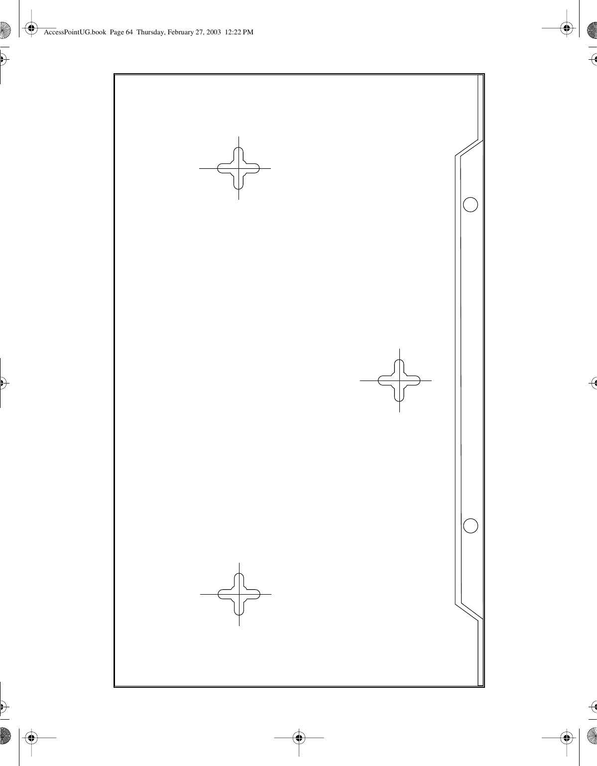
![63Using the Nortel Networks Wireless LAN Access Point 2220[Final Draft—Nortel Confidential]Appendix BTemplate for placing the Access Point 2220The template on the next page can be used to assist in positioning the Access Point2220. Mark where the wall-mount screws should go.AccessPointUG.book Page 63 Thursday, February 27, 2003 12:22 PM](https://usermanual.wiki/Accton-Technology/WA6101ACC/User-Guide-312417-Page-63.png)