Accton Technology WA6101ACC WLAN Access Point 2220 User Manual AccessPointUG
Accton Technology Corp WLAN Access Point 2220 AccessPointUG
Manual

[Final Draft—Nortel Confidential]
Part No. 214853-A
April 2003
4655 Great America Parkway
Santa Clara, CA 95054
Using the Nortel Networks
Wireless LAN Access Point
2220
AccessPointUG.book Page 1 Thursday, February 27, 2003 12:22 PM

2
214853-A
[Final Draft—Nortel Confidential]
Copyright Statement
No part of this publication may be reproduced, stored in a retrieval system, or transmitted in any form or by any means,
whether electronic, mechanical, photocopying, recording or otherwise without the prior writing of the publisher.
Windows 98SE/2000/ME/XP are trademarks of Microsoft Corp.
Pentium is trademark of Intel.
Nortel Networks and the Nortel Networks logo are trademarks of Nortel Networks, Inc.
All copyright reserved.
Compliances
Federal Communication Commission Interference Statement
This equipment has been tested and found to comply with the limits for a Class B digital device, pursuant to Part 15 of
the FCC Rules. These limits are designed to provide reasonable protection against harmful interference in a residential
installation. This equipment generates, uses and can radiate radio frequency energy and, if not installed and used in
accordance with instructions, may cause harmful and, if not installed and used in accordance with instructions, may
cause harmful interference to radio communications. However, there is no guarantee that the interference will not occur
in a particular installation. If this equipment does cause harmful interference to radio or television reception, which can
be determined by turning the equipment off and on, the user is encouraged to try to correct the interference by one or
more of the following measures:
• Reorient the receiving antenna
• Increase the separation between the equipment and receiver
• Connect the equipment into an outlet on a circuit different from that to which the receiver is connected
• Consult the dealer or an experienced radio/TV technician for help
FCC Caution: To assure continued compliance, (example - use only shielded interface cables when connecting to
computer or peripheral devices). Any changes or modifications not expressly approved by the party responsible for
compliance could void the user’s authority to operate this equipment.
This device complies with Part 15 of the FCC Rules. Operation is subject to the following two conditions: (1) This
device may not cause harmful interference, and (2) this device must accept any interference received, including
interference that may cause undesired operation.
CAUTION STATEMENT:
FCC Radiation Exposure Statement
FCC RF Radiation Exposure Statement
This equipment complies with FCC RF radiation exposure limits set forth for an uncontrolled environment. This
equipment should be installed and operated with a minimum distance of 20 centimeters (8 inches) between the radiator
and your body. This transmitter must not be co-located or operating in conjunction with any other antenna or transmitter.
Industry Canada - Class B
This digital apparatus does not exceed the Class B limits for radio noise emissions from digital apparatus as set out in the
interference-causing equipment standard entitled “Digital Apparatus,” ICES-003 of the Department of Communications.
AccessPointUG.book Page 2 Thursday, February 27, 2003 12:22 PM
this device is going to be operated in 5.15 ~5.25GHz frequency range, it is restricted in indoor environment only.

3
Using the Nortel Networks Wireless LAN Access Point 2220
[Final Draft—Nortel Confidential]
Cet appareil numérique respecte les limites de bruits radioélectriques applicables aux appareils numériques de Classe B
prescrites dans la norme sur le matériel brouilleur: “Appareils Numériques,” NMB-003 édictée par le ministère des
Communications.
AccessPointUG.book Page 3 Thursday, February 27, 2003 12:22 PM

4
214853-A
[Final Draft—Nortel Confidential]
AccessPointUG.book Page 4 Thursday, February 27, 2003 12:22 PM

5
Using the Nortel Networks Wireless LAN Access Point 2220
[Final Draft—Nortel Confidential]
Contents
Preface ......................................................13
Introduction .........................................................13
PackageChecklist .................................................13
HardwareDescription ..............................................13
EthernetCompatibility...........................................13
RadioCharacteristics ...........................................14
PoweroverEthernet ............................................14
LEDIndicators.................................................14
SystemRequirements ..............................................16
Chapter 1
HardwareInstallation...........................................17
Chapter 2
SystemConfiguration..........................................19
SetupWizard ........................................................20
Channel .........................................................22
IPConfiguration...................................................23
Security .........................................................24
64-Bit Manual Entry ............................................25
128-Bit Manual Entry . . . ........................................25
AdvancedSetup ..................................................26
System .............................................................26
Identification .....................................................26
TCP/IPSettings ..................................................27
Radius ..........................................................28
PPPoESettings ...................................................30
Authentication ....................................................31
802.1x Setup .....................................................32
AccessPointUG.book Page 5 Thursday, February 27, 2003 12:22 PM

6Contents
214853-A
[Final Draft—Nortel Confidential]
Local MAC Authentication . . . ........................................32
FilterControl .....................................................33
SNMP ..........................................................34
Administration ....................................................36
Change Password .............................................36
FirmwareUpgrade.............................................36
RestoreFactorySettings .......................................37
Reset Access Point ............................................37
SystemLog ......................................................37
RadioInterfaceB .....................................................39
RadioSettings ....................................................39
Radio Channel . . ..............................................39
MaximumStationDataRate ......................................39
Beacon Interval (20-1000) ........................................40
DTIM Period (1-16384) . . ........................................40
Fragment Length (256-2347) .....................................40
RTS Threshold (0-2347) . ........................................40
PreambleSetting...............................................41
Security .........................................................41
WEP(WiredEquivalentPrivacy)...................................41
Authentication Type Setup ........................................42
DataEncryption ...............................................42
Standard Key Setup (WEP Default: 128) . ...........................42
RadioInterfaceA .....................................................43
RadioSettings ....................................................43
TurboMode ...................................................44
Radio Channel . . ..............................................44
Auto Channel Select ............................................44
TransmitPower ................................................44
MaximumStationDataRate ......................................45
Beacon Interval (20-1000) ........................................45
DTIM Period (1-16384) . . ........................................45
RTS Threshold (0-2347) . ........................................45
Security .........................................................46
WEP(WiredEquivalentPrivacy)...................................46
AccessPointUG.book Page 6 Thursday, February 27, 2003 12:22 PM

Contents 7
Using the Nortel Networks Wireless LAN Access Point 2220
[Final Draft—Nortel Confidential]
Authentication Type Setup ........................................46
DataEncryption ...............................................47
Standard Key Setup (WEP Default: 128) . ...........................47
Status..............................................................48
AccessPointStatus................................................49
StationStatus ....................................................50
Event Logs . . .....................................................50
FindingtheMACaddressofaNetworkCard................................51
Windows98/ME...................................................51
Windows 2000/XP . . . ..............................................51
Chapter 3
NetworkConfigurationandPlanning..............................53
Network Topologies ...................................................53
Ad Hoc Wireless LAN
(noAPorBridge) ................................................53
InfrastructureWirelessLAN..........................................54
InfrastructureWirelessLANforRoamingWirelessPCs ....................54
Chapter 4
Troubleshooting. . . . . . . . . . . . . . . . . . . . . . . . . . . . . . . . . . . . . . . . . . . . . . . 57
Appendix A
Specifications.................................................59
MaximumChannels ..................................................59
MaximumClients ....................................................59
OperatingRange ....................................................59
DataRate...........................................................59
OperatingFrequency.................................................60
Powersupply .......................................................60
OutputPower .......................................................60
PhysicalSize .......................................................60
Weight .............................................................60
LEDIndicators ......................................................60
Management ........................................................60
Temperature ........................................................61
AccessPointUG.book Page 7 Thursday, February 27, 2003 12:22 PM

8Contents
214853-A
[Final Draft—Nortel Confidential]
Humidity ...........................................................61
Compliances........................................................61
Emissions ..........................................................61
Safety .............................................................61
Standards ..........................................................61
Warranty ...........................................................61
Appendix B
TemplateforplacingtheAccessPoint2220........................63
AccessPointUG.book Page 8 Thursday, February 27, 2003 12:22 PM

9
Using the Nortel Networks Wireless LAN Access Point 2220
[Final Draft—Nortel Confidential]
Figures
Figure1 LEDindicators .............................................15
Figure 2 Rear Panel . . ..............................................17
Figure 3 Login screen . ..............................................20
Figure4 MainMenu ................................................20
Figure5 SetupWizardscreen ........................................21
Figure6 SSIDscreen ...............................................22
Figure 7 Channel screen ............................................23
Figure8 TCP/IPSettingsscreen ......................................24
Figure9 Securityscreen.............................................25
Figure10 AdvancedSetupscreen ......................................26
Figure11 Identificationscreen .........................................27
Figure12 TCP/IPSettingsscreen ......................................27
Figure13 Radiusscreen..............................................28
Figure14 PPPoESetupscreen ........................................30
Figure 15 Authentication screen ........................................31
Figure16 FilterControlscreen .........................................33
Figure17 SNMPscreen ..............................................34
Figure18 Administrationscreen ........................................36
Figure19 SystemLogscreen..........................................38
Figure20 RadioSettingsscreen .......................................39
Figure21 Securityscreen.............................................41
Figure22 RadioSettingsscreen .......................................43
Figure23 Securityscreen.............................................46
Figure24 Statusscreen ..............................................48
Figure25 APStatusscreen ...........................................49
Figure26 StationStatusscreen ........................................50
Figure 27 Event Logs screen . . ........................................50
AccessPointUG.book Page 9 Thursday, February 27, 2003 12:22 PM

10 Figures
214853-A
[Final Draft—Nortel Confidential]
AccessPointUG.book Page 10 Thursday, February 27, 2003 12:22 PM

11
Using the Nortel Networks Wireless LAN Access Point 2220
[Final Draft—Nortel Confidential]
Tables
Table1 LEDIndicators .............................................15
Table 2 802.1x Setup ..............................................32
Table 3 Local MAC Authentication .....................................32
AccessPointUG.book Page 11 Thursday, February 27, 2003 12:22 PM

12 Tables
214853-A
[Final Draft—Nortel Confidential]
AccessPointUG.book Page 12 Thursday, February 27, 2003 12:22 PM

13
Using the Nortel Networks Wireless LAN Access Point 2220
[Final Draft—Nortel Confidential]
Preface
Introduction
The Nortel Networks Wireless LAN Access Point 2220 (Access Point 2220) is an
access point that provides transparent, wireless high-speed data communications
between the wired LAN and fixed, portable or mobile devices equipped with an
802.11a/802.11b (or A only card or B only card) wireless adapter employing the
same radio modulation.
This solution offers fast, reliable wireless connectivity with considerable cost
savings over wired LANs (which include long-term maintenance overhead for
cabling). Using 802.11a,11b technology, the Access Point 2220 can easily replace
a 10 Mbps Ethernet connection or seamlessly integrate into a 10/100 Ethernet
LAN.
Package Checklist
The Access Point 2220 package includes:
• One Access Point 2220
• Driver & Utility CD
• Documentation CD
Hardware Description
Ethernet Compatibility
The Access Point 2220 can attach directly to 10BASE-T/100BASE-TX
(twisted-pair) Ethernet LAN segments. These segments must conform to the IEEE
802.3 specification.
AccessPointUG.book Page 13 Thursday, February 27, 2003 12:22 PM

14 Preface
214853-A
[Final Draft—Nortel Confidential]
The access point appears as an Ethernet node and performs a routing function by
moving packets from the wired LAN to remote workstations on the wireless
infrastructure.
Radio Characteristics
For the A radio, the Access Point 2220 uses a radio modulation technique known
as Orthogonal Frequency Division Multiplexing (OFDM), and a shared collision
domain (CSMA/CA). It operates at the 5GHz Unlicensed National Information
Infrastructure (UNII) band with turbo mode. Data is transmitted over a
half-duplex radio channel operating at up to 108 Megabits per second (Mbps) in
turbo mode. The default mode is 54 Mbps.
Power over Ethernet
The Access Point 2220 supports Power over Ethernet (PoE). You need not
configure anything to access power from a IEEE 802.3af-draft-compliant switch.
To use PoE to power your Access Point 2220, plug in a cable to the RJ-45 port on
the back of the Access Point 2220 and connect the other end of the RJ-45 cable to
a switch that delivers IEEE 802.3af-draft-compliant power.
When you are using PoE, you do not require separate AC power. The Access Point
2220 draws 8.5 W.
The Access Point 2220 uses both spare and signal RJ-45 power pairs.
LED Indicators
The Access Point 2220 includes four status LED indicators, as described in the
following figure and table.
AccessPointUG.book Page 14 Thursday, February 27, 2003 12:22 PM

Preface 15
Using the Nortel Networks Wireless LAN Access Point 2220
[Final Draft—Nortel Confidential]
Figure 1 LED indicators
Table 1 LED Indicators
LED Status Description
Ready On Indicates that power is being supplied.
Flashing Indicates -
•running a self-test
•loading software program
system errors (refer to Chapter 4, “Troubleshooting”for
details)
LAN On Indicates a valid 10/100 Mbps Ethernet cable link.
Flashing Indicates that the access point is transmitting or
receivingdataona
10/100 Mbps Ethernet LAN. Flashing rate is
proportional to your network activity.
WLANa On Indicates a valid 802.11a wireless link.
Very Slow
Flashing Searching for network association.
Slow
Flashing Associated with network but no activity.
Fast
Flashing Indicates that the access point is transmitting or
receiving data through wireless links. Flashing rate is
proportional to network activity.
WLANb On Indicates a valid 802.11b wireless link.
Very Slow
Flashing Searching for network association.
Slow
Flashing Associated with network but no activity.
Fast
Flashing Indicates that the access point is transmitting or
receiving data through wireless links. Flashing rate is
proportional to network activity.
Power 802.11a
Wireless
Link/Activity
Ethernet
Link/Activity 802.11b
Wireless
Link/Activity
AccessPointUG.book Page 15 Thursday, February 27, 2003 12:22 PM

16 Preface
214853-A
[Final Draft—Nortel Confidential]
System Requirements
Before you install the Access Point 2220, be sure you can meet the following
requirements:
• An A/C power outlet (100~240 V, 50~60 Hz) which will supply power for the
access point (Alternatively, you can plug into a switch that delivers Power
over Ethernet to power the Access Point 2220.)
• 802.11a or 802.11b compliant (or dual-compliant) wireless Ethernet adapters
with TCP/IP compatible protocol installed
• Web browser for configuration
Alternatively, you can connect an RS-232 cable to the console port and use the
command line interface (CLI). For more information on the CLI, refer to Run
Time Console Specifications.
Optivity* NMS also works with the Access Point 2220.
AccessPointUG.book Page 16 Thursday, February 27, 2003 12:22 PM
17
Using the Nortel Networks Wireless LAN Access Point 2220
[Final Draft—Nortel Confidential]
Chapter 1
Hardware Installation
1Placement of the Access Point 2220 – Choose a proper place for your Access
Point 2220. In general, the best location is at the center of your wireless
coverage area, within line of sight of all wireless devices. Try to place the
access point in a position that can best cover its BSS. Normally, the higher
you place the access point, the better the performance. (Refer to Appendix B,
“Template for placing the Access Point 2220,” for information on mounting
the Access Point 2220.)
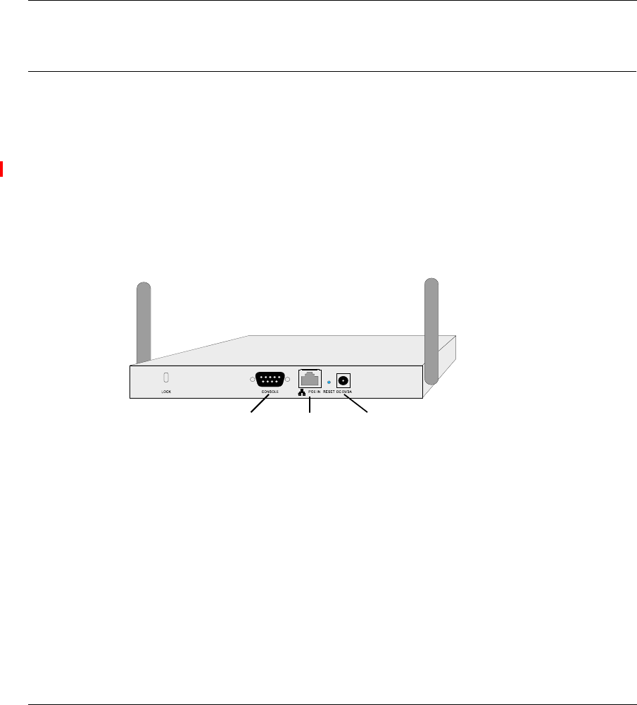
Figure 2 Rear Panel
2Connect the Console Port – Connect the console cable to the RS-232 console
port for accessing the command-line interface. (Refer to “Run Time Console
Specifications“ for complete information on the CLI.) You can manage the
access point through this console connection, or the Web management
interface (refer to “System Configuration” on page 19.)
3Connect the Ethernet Cable – The Access Point 2220 can be wired to a 10/100
Mbps Ethernet through a network device such as a hub or a switch. Connect to
the RJ-45 connector socket on the back panel with category 3, 4, or 5 UTP
Ethernet cable and an RJ-45 connector.
5VDC
Power Socket
RJ-45
Connector
(PoE)
Console
Port
AccessPointUG.book Page 17 Thursday, February 27, 2003 12:22 PM

18 Chapter 1 Hardware Installation
214853-A
[Final Draft—Nortel Confidential]
4If you are not using PoE, use the separately orderable power adapter –
Connect the power adapter cable to the 5 VDC power socket on the rear panel.
Warning: Use ONLY the power adapter supplied by Nortel Networks for
this product. Otherwise, the product may be damaged. Contact your
Nortel Networks representative to order the power adapter.
AccessPointUG.book Page 18 Thursday, February 27, 2003 12:22 PM

Chapter 2 System Configuration 19
Using the Nortel Networks Wireless LAN Access Point 2220
[Final Draft—Nortel Confidential]
Chapter 2
System Configuration
The Access Point 2220 can be configured by any Java-supported Web browser
including Internet Explorer 4.0 or above, or NetScape Navigator 4.0 or above.
Using the Web management interface, you may configure the Access Point 2220.
You can also use the command line interface (CLI) to manage the Access Point
2220. (Refer to “Run Time Console Specifications“ for complete information on
the CLI.)
To initially manage the Access Point 2220, you must configure the network
settings of the computers on your wireless LAN to use the same IP subnet as the
Access Point 2220. The default network settings assuming there is no external
DHCP server for this device are:
Access Point IP Address: 192.168.168.10
Gateway IP Address: 192.168.168.254
Subnet Mask: 255.255.255.0
The IP address of the connected client PC from which system configuration is to
be performed should be 192.168.168.x (where x means 1–9, 11–253).
If DHCP is enabled, (default setting is “Enable,” page 41) and a DHCP server is
located on the network, then the access point will automatically be assigned an IP
address when booted.
To access the Access Point 2220’s management interface, enter the IP address of
the device in your Web browser:
http://192.168.168.10
The Web management window will appear.
AccessPointUG.book Page 19 Thursday, February 27, 2003 12:22 PM
20 Chapter 2 System Configuration
214853-A
[Final Draft—Nortel Confidential]
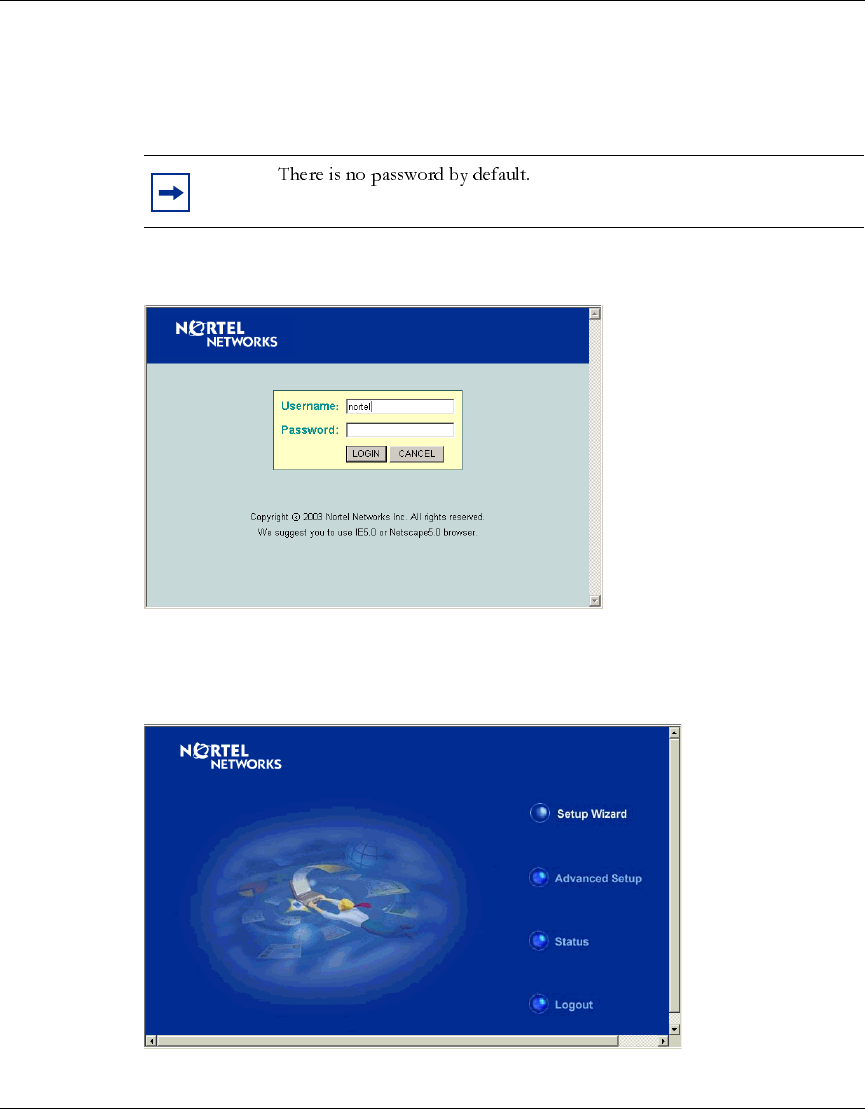
Setup Wizard
1To access the management interface, enter the username “nortel” and click
“LOGIN.”
Figure 3 Login screen
2The home page displays the Main Menu.
Figure 4 Main Menu
Note:
AccessPointUG.book Page 20 Thursday, February 27, 2003 12:22 PM
Chapter 2 System Configuration 21
Using the Nortel Networks Wireless LAN Access Point 2220
[Final Draft—Nortel Confidential]
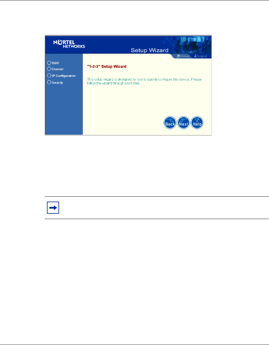
3Click “Setup Wizard” to open the “1-2-3” Setup Wizard.
Figure 5 Setup Wizard screen
4Click the “Next” button to start basic configuration.
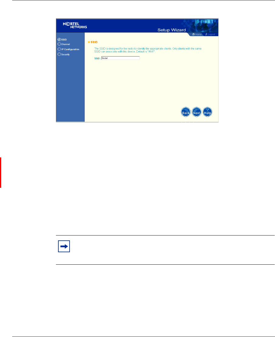
SSID – The Service Set ID. This should be set to the same value as other
wireless devices in your network.
(Default: Nortel)
Note: The SSID is case sensitive and can consist of up to 32
alphanumeric characters.
AccessPointUG.book Page 21 Thursday, February 27, 2003 12:22 PM
22 Chapter 2 System Configuration
214853-A
[Final Draft—Nortel Confidential]
Figure 6 SSID screen
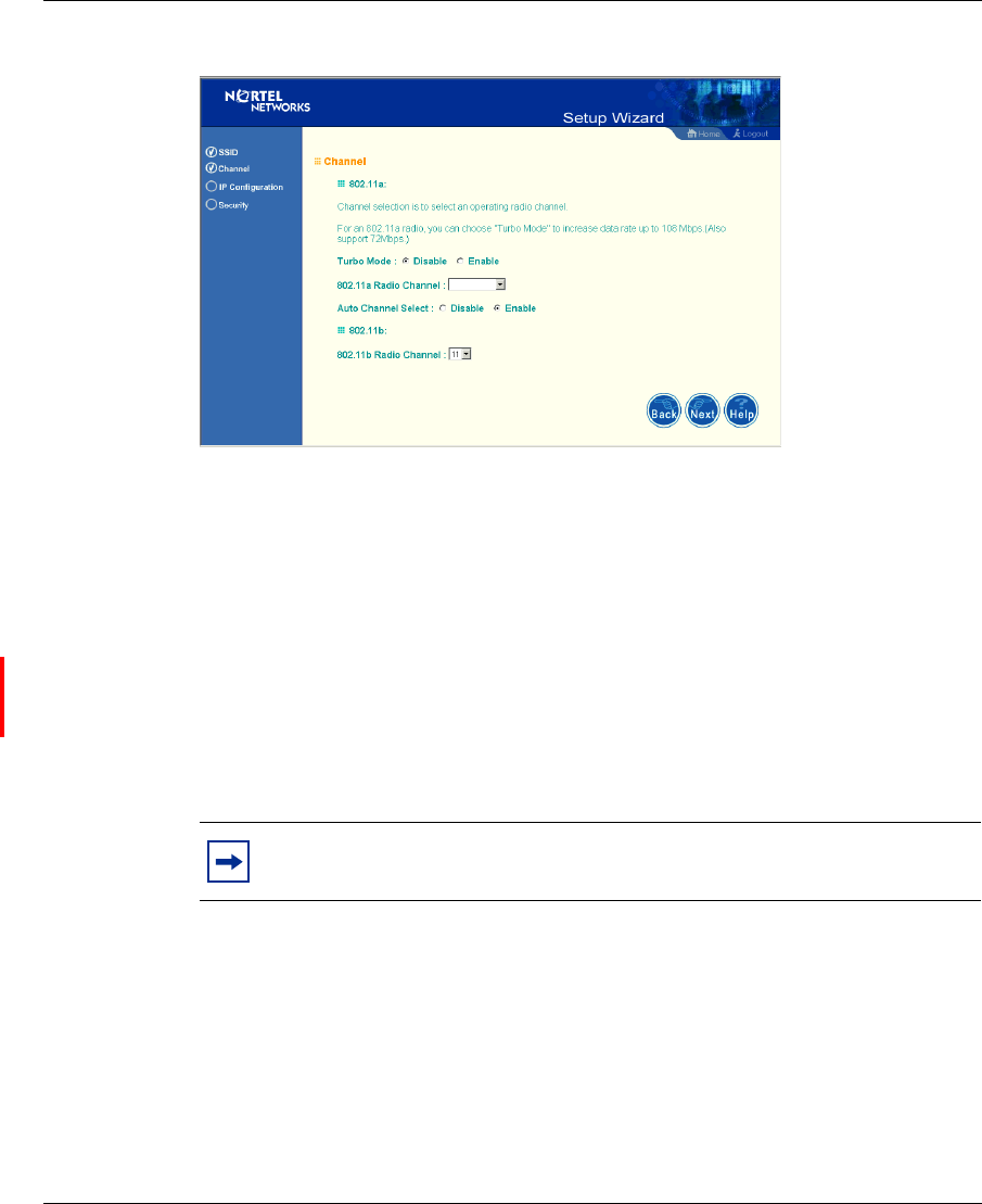
Channel
802.11a: – If you select “Enable” the access point will operate in Turbo mode
with a data rate of up to 108 Mbps. By default, the Access Point 2220 operates at
54 Mbps. If you enable Turbo mode, the Access Point 2220 operates up to 108
Mbps. (Turbo mode default: Disable)
Auto Channel Select: Selecting “Enable” allows for automatic radio channel
detection. (Default: “Enable”)
802.11b: – Set the operating radio channel number (Default: 11)
Note: Available channel settings are limited by local regulations which
determine which channels are available. (Refer to “Radio Channel” on
page 39.)
AccessPointUG.book Page 22 Thursday, February 27, 2003 12:22 PM
Chapter 2 System Configuration 23
Using the Nortel Networks Wireless LAN Access Point 2220
[Final Draft—Nortel Confidential]
Figure 7 Channel screen
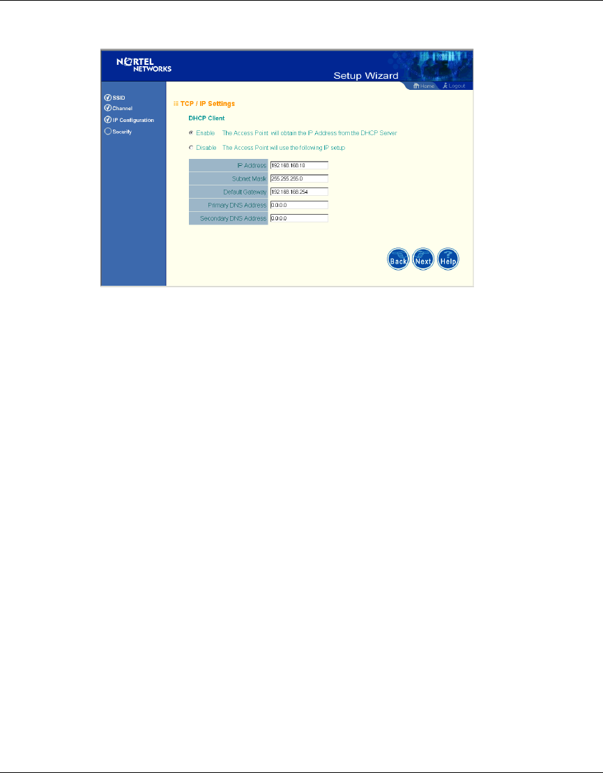
IP Configuration
DHCP Client: With DHCP (Dynamic Host Configuration Protocol) Client
enabled, the IP address, subnet mask and default gateway can be dynamically
assigned to the access point by an external network DHCP server on the network.
This device implements a DHCP client but not a DHCP server.
(Default: Enable)
DNS (Domain Name Servers) map domain name (e.g.,nortel.com) to the
equivalent numerical IP addresses. Your network administrator should provide the
IP address of one or more domain name servers. Enter those addresses on the
following screen.
Note: If there is no DHCP server on your network, then the access point
will automatically start up with its default IP address, 192.168.168.10.
AccessPointUG.book Page 23 Thursday, February 27, 2003 12:22 PM
24 Chapter 2 System Configuration
214853-A
[Final Draft—Nortel Confidential]
Figure 8 TCP/IP Settings screen
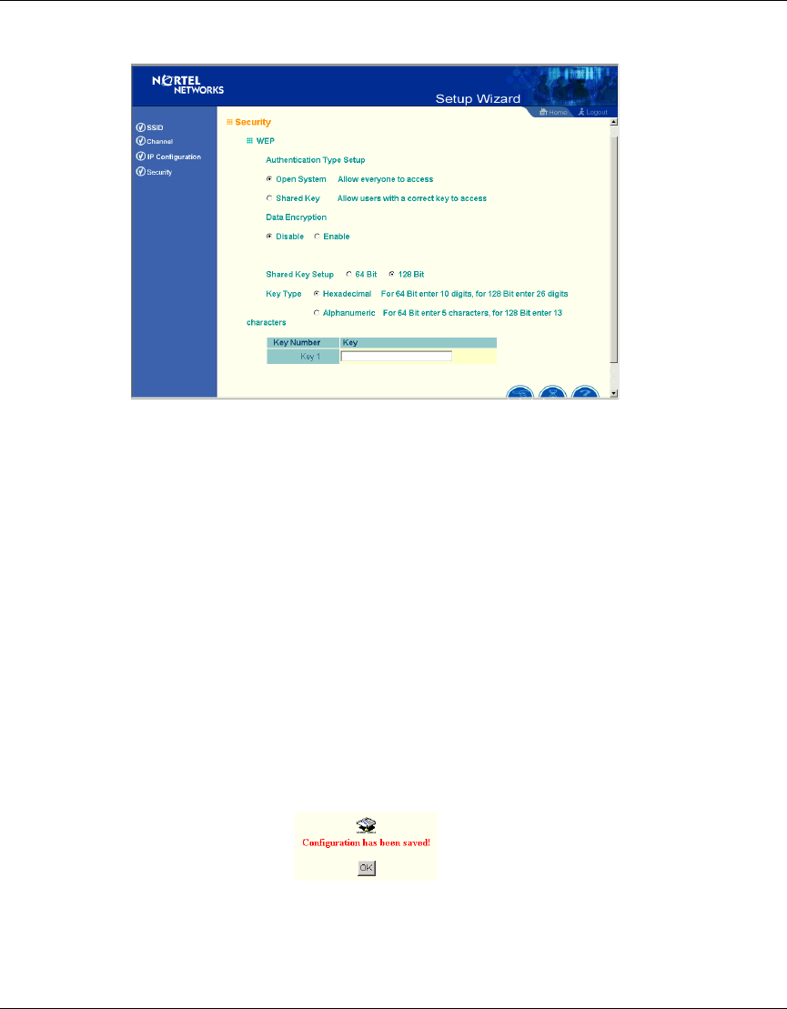
Security
WEP – Wired Equivalent Privacy (WEP) is implemented in this device to prevent
unauthorized access to your wireless network.
Authentication Type: Click on the “Shared Key” radio button to start filtering the
frames with the addresses defined in the “Shared Key Setup” field. (Default: Open
System)
Shared Key Setup: For more secure data transmission, check the “Enable” radio
button in the “Data Encryption” field. Then select one shared key size and the key
number. (WEP Default: Disable)
AccessPointUG.book Page 24 Thursday, February 27, 2003 12:22 PM
Chapter 2 System Configuration 25
Using the Nortel Networks Wireless LAN Access Point 2220
[Final Draft—Nortel Confidential]
Figure 9 Security screen
The Access Point 2220 supports “Shared Key” encryption with key lengths of the
standard 64-bit and industry standard 128-bit. The bit key can be in alphanumeric
characters, or hexadecimal numerals (0~9, A~F, e.g., D7 0A 9C 7F E5.) All
wireless devices must have the same Key ID values to communicate.
64-Bit Manual Entry
Key 1~4 - Each Key ID contains 10 HEX digits, or 5 alphanumeric characters.
128-Bit Manual Entry
Key ID contains 26 HEX digits, or 13 alphanumeric characters.
1Click “Finish.”
2Click the “OK” button to restart the access point.
AccessPointUG.book Page 25 Thursday, February 27, 2003 12:22 PM
26 Chapter 2 System Configuration
214853-A
[Final Draft—Nortel Confidential]
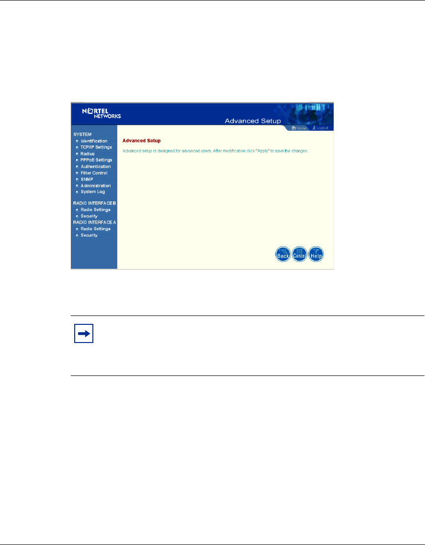
Advanced Setup
Click “Advanced Setup” on the Home page to open the Advanced Setup page.
(See the screen on page 20.)
Figure 10 Advanced Setup screen
System
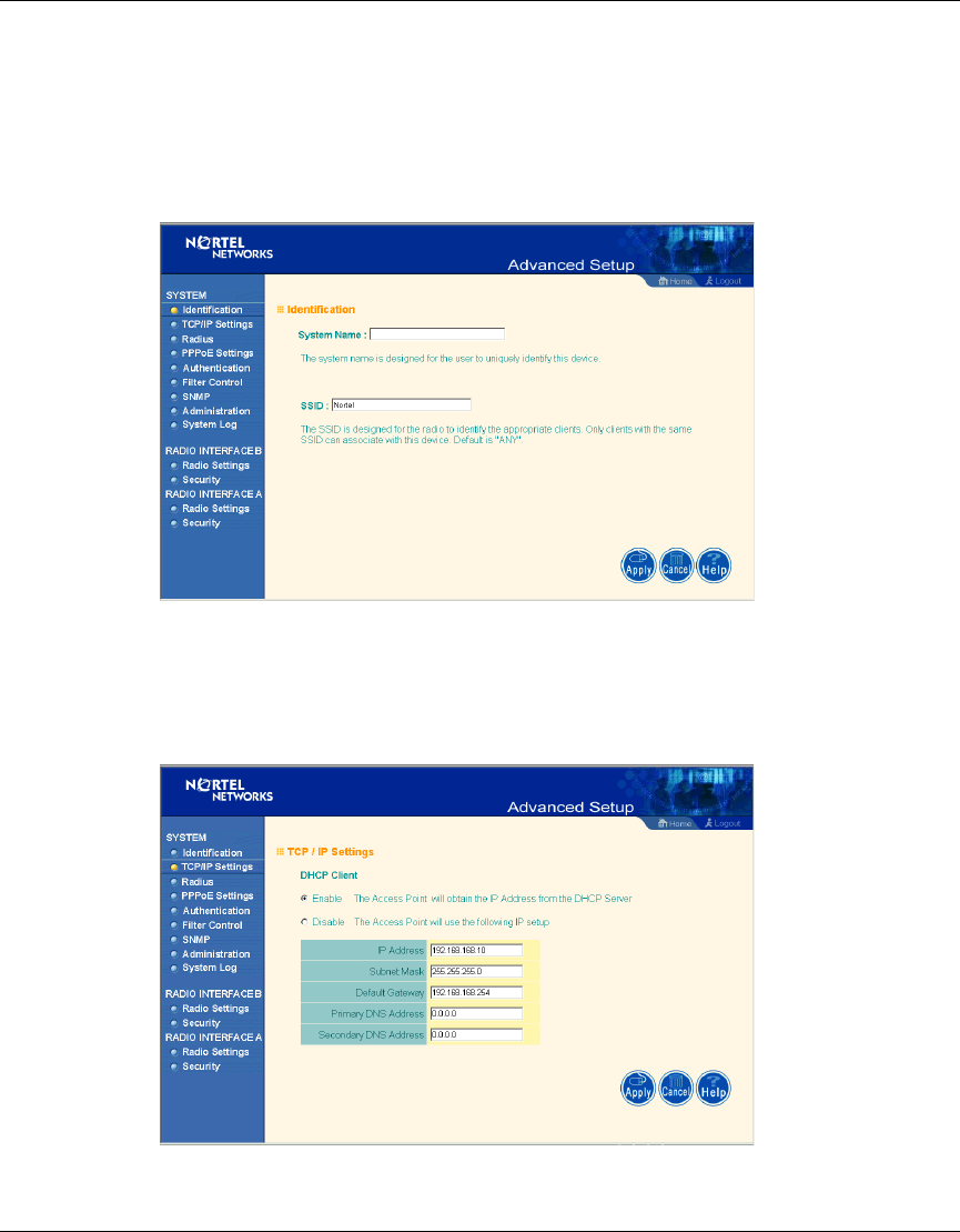
Identification
System Name: You can easily identify the access point by providing a descriptive
name. Enter a maximum of 32 characters in the System Name field.
Note: The “Advanced Setup” screen allows you to view and change the
current configuration of the access point. After modifying the
configuration parameters, you must click on the “Apply” button to save
the changes.
AccessPointUG.book Page 26 Thursday, February 27, 2003 12:22 PM
Chapter 2 System Configuration 27
Using the Nortel Networks Wireless LAN Access Point 2220
[Final Draft—Nortel Confidential]
SSID: The SSID (Service Set Identification) is the name of a basic service set
provided by an access point. Clients that want to connect to the wireless network
via an access point must set their SSIDs to the same as that of the access point.
(SSID Default: Nortel). (The default system location is the MAC address.)
Figure 11 Identification screen
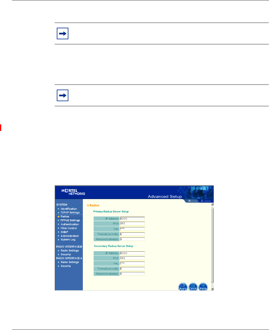
TCP / IP Settings
Figure 12 TCP/IP Settings screen
AccessPointUG.book Page 27 Thursday, February 27, 2003 12:22 PM
28 Chapter 2 System Configuration
214853-A
[Final Draft—Nortel Confidential]
DHCP Client: With DHCP (Dynamic Host Configuration Protocol) Client
enabled, the IP address, subnet mask and default gateway can be dynamically
assigned to the access point by the network DHCP server. (Default: Enable)
DNS (Domain Name Servers) map numerical IP addresses to the equivalent
domain name (e.g., www.nortelnetworks.com). Your network administrator
should provide the IP address of one or more domain name servers. Enter those
addresses on this screen.
Radius
Figure 13 Radius screen
Note: You must turn off DHCP for the manual TCP/IP to be accepted.
Note: If there is no DHCP server on your network, then the access point
will automatically start up with its default IP address, 192.168.168.10.
AccessPointUG.book Page 28 Thursday, February 27, 2003 12:22 PM

Chapter 2 System Configuration 29
Using the Nortel Networks Wireless LAN Access Point 2220
[Final Draft—Nortel Confidential]
Remote Authentication Dial-in User Service (RADIUS) is a logon authentication
protocol that uses software running on a central server to control access to
RADIUS-compliant devices on the network. It allows a wireless access point to
send the connection parameters to a RADIUS server. Enter the required
parameters as shown on the screen, which includes the RADIUS server IP
address, controlled port number, per-client unicast session key, timeout value (in
seconds), and retransmit attempts number.
The following RADIUS servers are supported by the Access Point 2220:
• Microsoft IAS: Windows 2000 Server Build 2195 Service Pack 2: TLS, Mac
Radius
• Funk Odyssey Server (Version 1.0): TTLS, TLS
IP Address – Address of authentication server. (Default: 0.0.0.0)
Port – Network (UDP) port of authentication server used for authentication
messages (Range: 1-65535; Default: 1812)
Key – Encryption key used to authenticate logon access for client. Do not use
blank spaces in the string. (Maximum length: 255 characters)
Timeout – The number of seconds the access point waits for a reply from the
RADIUS server before it resends the request. (Range: 1-60; Default: 5)
Retransmit attempts – Number of times the access point will try to authenticate
logon access via the authentication server. (Range: 1-30; Default: 3)
AccessPointUG.book Page 29 Thursday, February 27, 2003 12:22 PM
30 Chapter 2 System Configuration
214853-A
[Final Draft—Nortel Confidential]
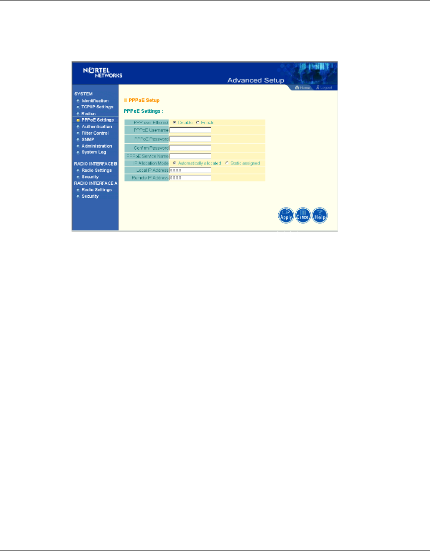
PPPoE Settings
Figure 14 PPPoE Setup screen
Enter the PPPoE user name and password assigned by your Service Provider. The
Service Name is normally optional, but may be required by some service
providers.
Some xDSL Internet Service Providers may assign a fixed (static) IP address. If
you have been provided with this information, click on the “Static assigned” for
the “IP Allocation Mode,” and enter the assigned “Local IP Address” and
“Remote IP addresses.”
AccessPointUG.book Page 30 Thursday, February 27, 2003 12:22 PM
Chapter 2 System Configuration 31
Using the Nortel Networks Wireless LAN Access Point 2220
[Final Draft—Nortel Confidential]
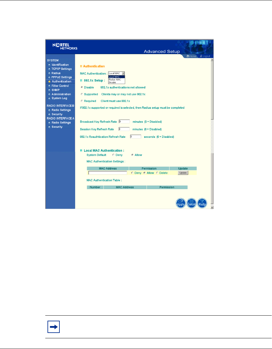
Authentication
Figure 15 Authentication screen
Management access will be checked against the authentication database stored on
the access point. If a remote authentication server is used, you must specify the
authentication sequence and the corresponding parameters (see “Radius” on page
28) for the remote authentication protocol.
MAC Authentication (Default: Local MAC)
Selecting the MAC authentication allows you to define access permission and
precedence. For Local MAC Authentication go to page 32. For Radius MAC
Authentication see the following page.
Note: Be sure to set up the Radius MAC authentication for the client on
the Radius server before using the Radius MAC service.
AccessPointUG.book Page 31 Thursday, February 27, 2003 12:22 PM

32 Chapter 2 System Configuration
214853-A
[Final Draft—Nortel Confidential]
802.1x Setup
Click the “Supported” or “Required” radio button on the 802.1x Setup field when
using the Radius MAC authentication.
Local MAC Authentication
Client computers can be filtered using the unique MAC address of their IEEE
802.11 network card. To secure an access point using local MAC address filtering,
you must enter a list of allowed/denied client MAC addresses into the filtering
table. (See “Finding the MAC address of a Network Card” on page 51.)
Table 2 802.1x Setup
Field Defaults Description
Broadcast Key
Refresh Rate 0(in
minutes) Defines how long the radius server will
refresh the primary broadcast key
Session Key
Refresh Rate 0(in
minutes) Defines how long the radius server will
dynamically re-assign a session key to a
connected client station.
802.1x
Reauthentication
Refresh Rate
0(in
seconds) Defines how long the radius server will
dynamically re-assign session keys to
the all connected client stations.
Table 3 Local MAC Authentication
Parameter Description
System Default Define the default filtering setting as “Deny”
or “Allow.”
MAC Address Manually type in the MAC address of a
client for the access control
Permissions Allows/Denies access of devices matching
a specified source IP address in the list to
connect to the access point.
Update Click the “Update”button to refresh the
settings.
AccessPointUG.book Page 32 Thursday, February 27, 2003 12:22 PM
Chapter 2 System Configuration 33
Using the Nortel Networks Wireless LAN Access Point 2220
[Final Draft—Nortel Confidential]
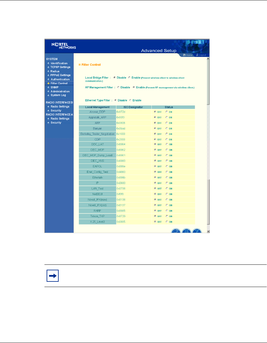
Filter Control
Figure 16 Filter Control screen
Local Bridge Filter
Using this filter function prevents direct node-to-node connection for more secure
wireless network. (Default: Disable)
Note: The current screen displays “Deny” rather than “ON,” and “allow”
rather than “OFF.”
AccessPointUG.book Page 33 Thursday, February 27, 2003 12:22 PM
34 Chapter 2 System Configuration
214853-A
[Final Draft—Nortel Confidential]
AP Management Filter
The administration management can be protected with AP Management Filter.
(Default: Enable)
Ethernet Type Filter
Use the “Ethernet Type Filter” table to filter out Ethernet packet frames matching
Ethernet protocol type. (Default: Disable)
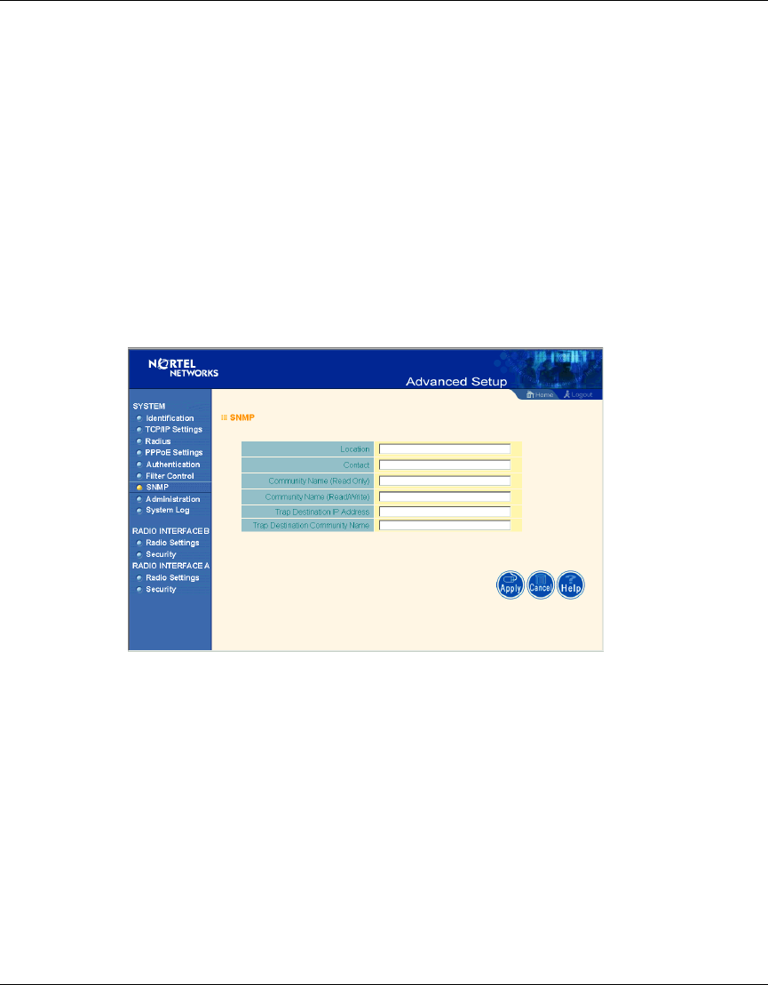
SNMP
Figure 17 SNMP screen
Use this screen to display and enter a community string for the Simple Network
Management Protocol (SNMP). To communicate with the access point, the SNMP
agent must first be enabled, and the Network Management Station must submit a
valid community string for authentication.
Location - Specifies the access point location
Contact - Set the system location string, that describes the system location.
(Maximum length: 255 characters)
AccessPointUG.book Page 34 Thursday, February 27, 2003 12:22 PM

Chapter 2 System Configuration 35
Using the Nortel Networks Wireless LAN Access Point 2220
[Final Draft—Nortel Confidential]
Community Name (Read Only) - Specifies a community string with read-only
access. Authorized management stations are only able to retrieve MIB objects.
(Maximum length: 23 characters)
Community Name (Read/Write) - Specifies a community string with read-write
access. Authorized management stations are able to both retrieve and modify MIB
objects. (Maximum length: 23 characters)
Trap Destination IP Address - Fill in the IP address box for a trap manager that
will receive these messages.
Trap Destination Community Name - Fill in the community string box for a trap
manager that will receive these messages. (Maximum length: 23 characters)
AccessPointUG.book Page 35 Thursday, February 27, 2003 12:22 PM
36 Chapter 2 System Configuration
214853-A
[Final Draft—Nortel Confidential]
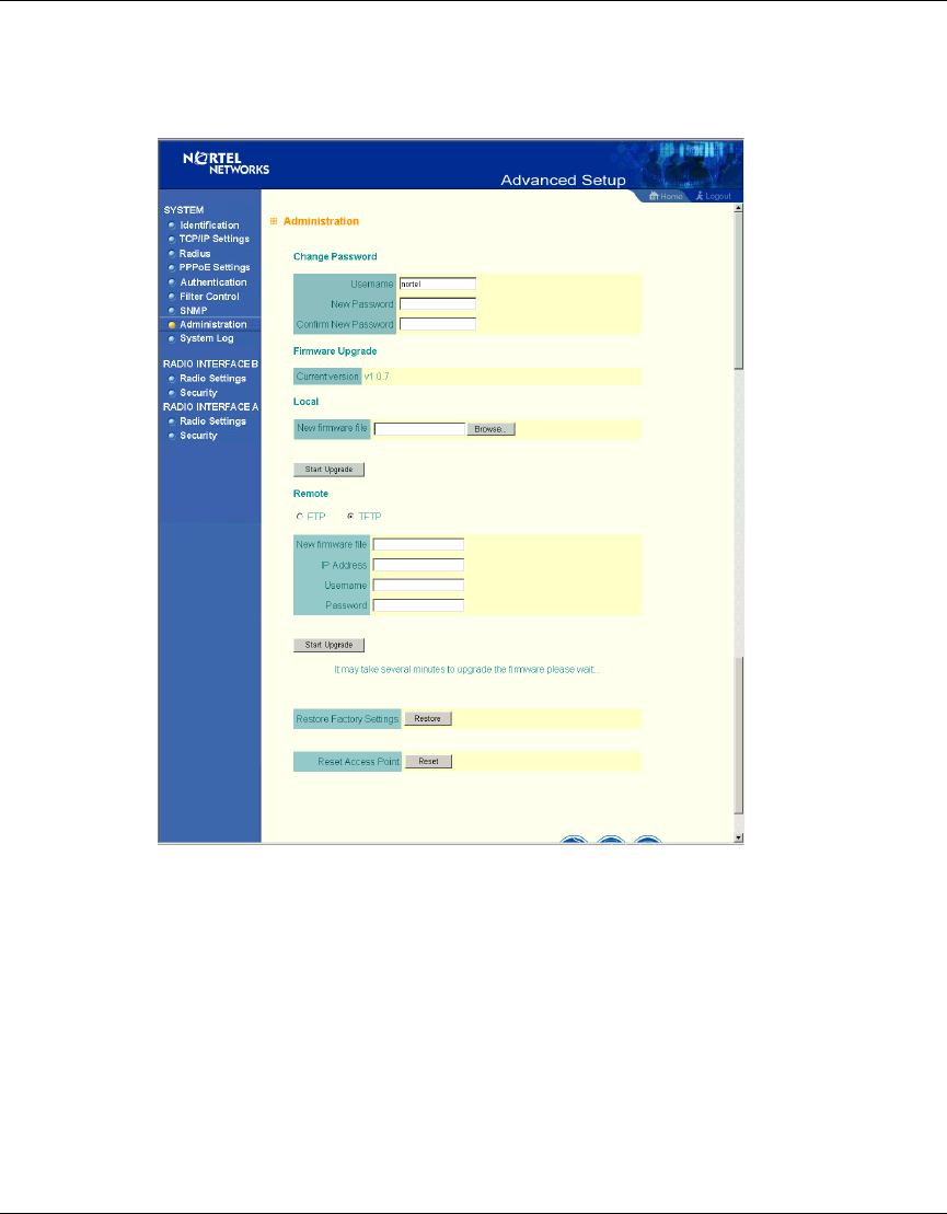
Administration
Figure 18 Administration screen
Change Password
Use this section to change the password on the access point.
Firmware Upgrade
Local - Click “Browse” to locate the downloaded firmware file and click “Start
Upgrade” to start the upgrade process.
AccessPointUG.book Page 36 Thursday, February 27, 2003 12:22 PM
Chapter 2 System Configuration 37
Using the Nortel Networks Wireless LAN Access Point 2220
[Final Draft—Nortel Confidential]
Remote - Select FTP or TFTP, and enter firmware file name, the host IP address,
user name, and password. Click “Start Upgrade” to start the upgrade process.
For latest firmware version information, visit Nortel’s Web site at:
www.nortelnetworks.com and click Software Downloads under the Support
heading.
Restore Factory Settings
Click the “Restore” button to load the factory default configuration and reboot this
device. Note that all user configured information will be lost. You will also have to
re-enter the default user name (nortel) to regain management access to this device.
Reset Access Point
Clicking on the “Reset” button to perform a hardware reset of the access point.
System Log
New screen coming with SNTP enhancements.
Note: Current configurations will not be changed.
AccessPointUG.book Page 37 Thursday, February 27, 2003 12:22 PM
38 Chapter 2 System Configuration
214853-A
[Final Draft—Nortel Confidential]
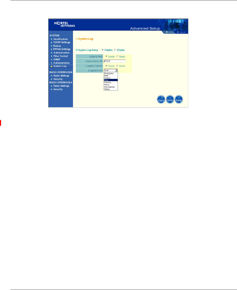
Figure 19 System Log screen
The System Log allows you to setup a log server with various logging level (as
shown on the above screen). (Default: Disable)
AccessPointUG.book Page 38 Thursday, February 27, 2003 12:22 PM
Chapter 2 System Configuration 39
Using the Nortel Networks Wireless LAN Access Point 2220
[Final Draft—Nortel Confidential]
Radio Interface B
Radio Settings
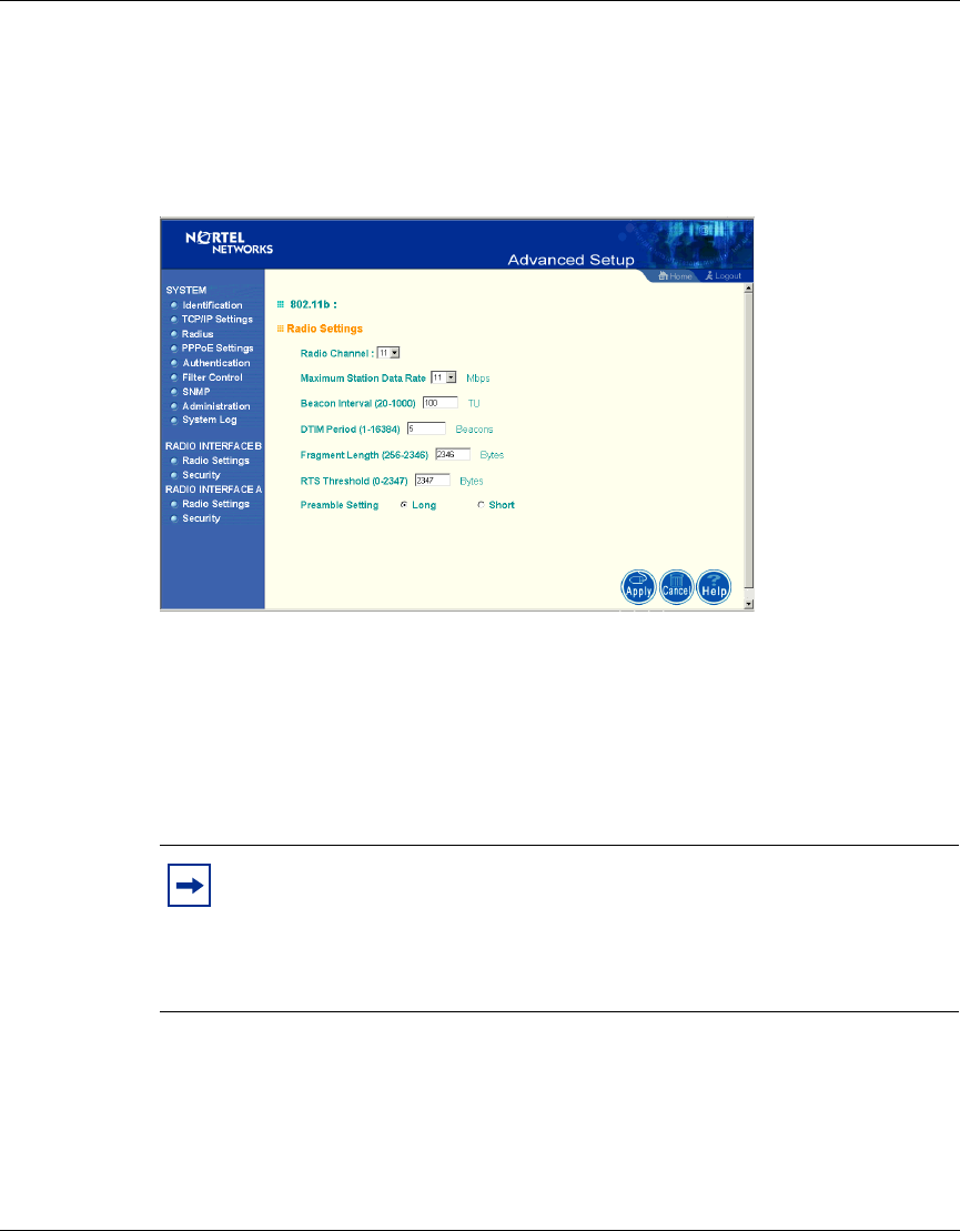
Figure 20 Radio Settings screen
Radio Channel
The radio channel through which the access point communicates to PCs in its
BSS. (Default: “11”) Note that the client channel for wireless users is
automatically set to the same as that used by the access point to which it is linked.
Maximum Station Data Rate
Select the appropriate data rate from the drop-down list for the data transfer speed
running on your network. (Default: 11 Mbps)
Note: The available channel settings are limited by local regulations,
which determine the number of channels that are available.
- FCC: 11 channels
- MKK: 14 channels
AccessPointUG.book Page 39 Thursday, February 27, 2003 12:22 PM

40 Chapter 2 System Configuration
214853-A
[Final Draft—Nortel Confidential]
Beacon Interval (20-1000)
Sets the beacon signal interval. The beacon signals allow the wireless devices to
maintain contact with each other. They may also carry power-management
information. (Default: 100 TU)
DTIM Period (1-16384)
Sets the Delivery Traffic Indication Map (DTIM) packet interval value. The DTIM
indicates how often the MAC layer forwards multicast traffic. This parameter is
necessary to wake up stations that are using Power Save mode.
The DTIM is the interval between two synchronous frames with broadcast
information. If you set the value to 2, the access point will save all multicast
frames for the BSS and forward them after every second beacon. Having smaller
DTIM intervals delivers multicast frames in a more timely manner, causing
stations in Power Save mode to wake up more often and drain power faster.
Having higher DTIM values reduces the power used by stations in Power Save
mode, but delays the transmission of multicast frames. (Default: 5 Beacons)
Fragment Length (256-2347)
The “Fragment Length” can be set between 256 and 2,346. If the packet size is
smaller than the preset Fragment size, the packet will not be segmented.
Fragmentation of the PDUs (Package Data Unit) can increase the reliability of
transmissions because it increases the probability of a successful transmission due
to smaller frame size. If there is significant interference present, or collisions due
to high network utilization, try setting the fragment size to send smaller
fragments. This will speed up the retransmission of smaller frames. However, it is
more efficient to set the fragment size larger if very little or no interference is
present because it requires overhead to send multiple frames. (Default: 2347)
RTS Threshold (0-2347)
Set the RTS (Request to Send) frame length. You may configure the access point
to initiate an RTS frame sequence always, never, or only on frames longer than a
specified length. If the packet size is smaller than the preset RTS threshold size,
the RTS/CTS mechanism will NOT be enabled
AccessPointUG.book Page 40 Thursday, February 27, 2003 12:22 PM
Chapter 2 System Configuration 41
Using the Nortel Networks Wireless LAN Access Point 2220
[Final Draft—Nortel Confidential]
The access point sends Request to Send (RTS) frames to a particular receiving
station to negotiate the sending of a data frame. After receiving an RTS frame, the
station sends a CTS (Clear to Send) frame to acknowledge the right of the sending
station to send data frames. The access points contending for the medium may not
be aware of each other. The RTS/CTS mechanism can solve this “Hidden Node
Problem.” (Default: 2347)
Preamble Setting
The access points and client card drivers have a radio setting for RF Preamble. Set
it to short for better throughput; although this setting may cause interoperability
issues with the NIC. (Default: Long)
Security
WEP (Wired Equivalent Privacy)
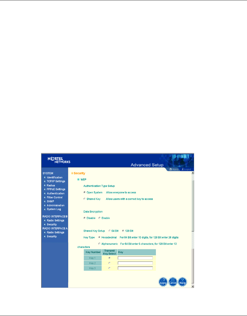
Figure 21 Security screen
AccessPointUG.book Page 41 Thursday, February 27, 2003 12:22 PM

42 Chapter 2 System Configuration
214853-A
[Final Draft—Nortel Confidential]
WEP is implemented in this device to prevent unauthorized access to your
wireless network. The WEP setting must be the same on each client in your
wireless network.
Authentication Type Setup
You may choose either “Open System” or “Shared Key.”
(Default: Open System)
If Shared Key is enabled, WEP should be enabled and at least one shared key
should be defined.
Data Encryption
You may choose “Enable” to enhance your network security with WEP data
encryption
(Default: Disable)
If Shared Key is enabled, WEP should be enabled and at least one shared key
should be defined.
Standard Key Setup (WEP Default: 128)
Default Shared Key – Choose the Shared Key that has the encryption string you
prefer (Key 1~3).
The access point supports “Shared Key” encryption with key lengths of the
standard 64-bit and industry standard 128-bit. The bit key can be in alphanumeric
characters, or hexadecimal numerals (0~9, A~F, e.g., D7 0A 9C 7F E5.)
64-Bit Manual Entry
Key 1~3 - Each Key ID contains 10 HEX digits, or 5 alphanumeric characters.
AccessPointUG.book Page 42 Thursday, February 27, 2003 12:22 PM
Chapter 2 System Configuration 43
Using the Nortel Networks Wireless LAN Access Point 2220
[Final Draft—Nortel Confidential]
128-Bit Manual Entry
Key ID contains 26 HEX digits, or 13 alphanumeric characters.
1Select a unique key (1~3)
2Enter the encryption key and select the key size.
3Be sure to click the “Apply” button on the bottom of the page to make the
settings take effect.
Radio Interface A
Radio Settings
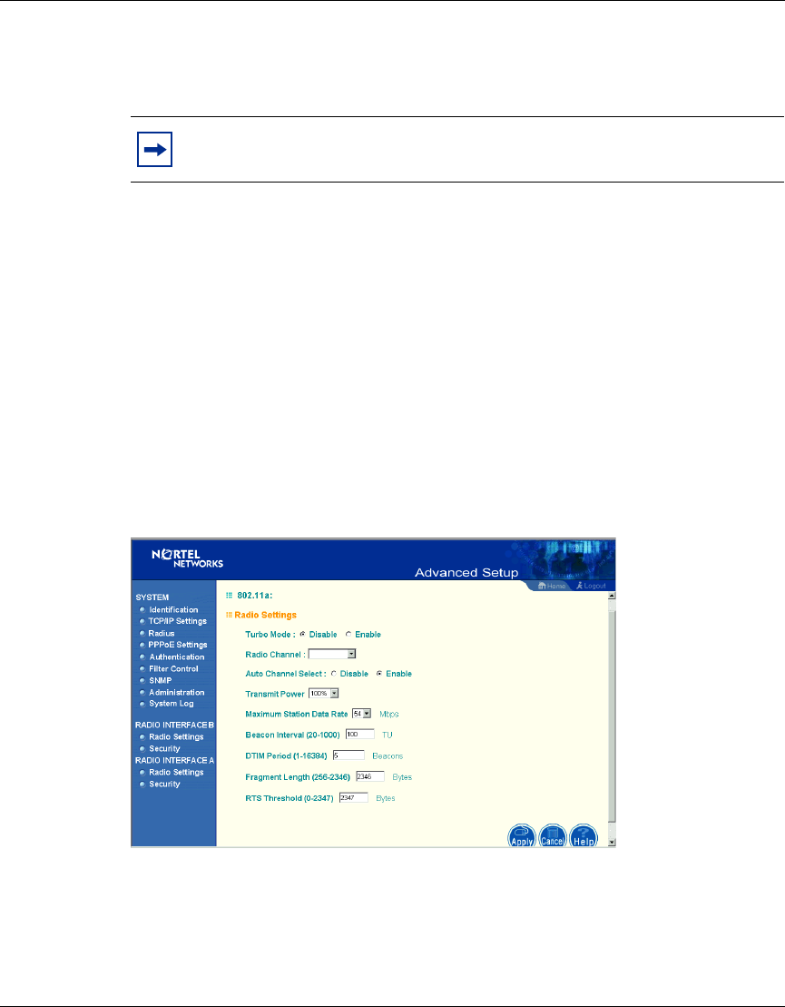
Figure 22 Radio Settings screen
Note: All wireless devices must have the same Key ID values to
communicate.
AccessPointUG.book Page 43 Thursday, February 27, 2003 12:22 PM

44 Chapter 2 System Configuration
214853-A
[Final Draft—Nortel Confidential]
Turbo Mode
You may either “Enable” or “Disable” the “Turbo Mode.”
(Default: Disable)
“Turbo Mode” is the enhanced wireless LAN operating mode (not regulated in the
standard IEEE 802.11a) that can provide a higher data rate. The “Normal Mode”
of the 802.11a access point provides connections up to 54 Mbps. Enabling “Turbo
Mode” on the 802.11a access point allows the access point to provide connections
up to 108 Mbps.
In “Normal Mode,” the channel bandwidth is 20MHz. In “Turbo Mode,” the
channel bandwidth is increased to 40MHz. However, there will only be three
channels available when “Turbo Mode” is enabled (only 1 channel in Japan).
Radio Channel
The radio channel through which the access point communicates to PCs in its
BSS. Note that the client channel for wireless users is automatically set to the
same as that used by the access point to which it is linked.
Auto Channel Select
Selecting “Enable” allows for automatic radio channel detection.
(Default: “Enable”)
Transmit Power
Set the signal strength transmitted from the access point. The longer the
transmission distance, the higher the transmission power required. (Default:
100%)
Note: The available channel settings are limited by local regulations,
which determine the number of channels that are available.
- FCC: 12 channels
- MKK: 5 channels
AccessPointUG.book Page 44 Thursday, February 27, 2003 12:22 PM

Chapter 2 System Configuration 45
Using the Nortel Networks Wireless LAN Access Point 2220
[Final Draft—Nortel Confidential]
Maximum Station Data Rate
Select the appropriate data rate from the drop-down list for the data transfer speed
running on your network. (Default: 54 Mbps)
Beacon Interval (20-1000)
Sets the beacon signal interval. The beacon signals allow the wireless devices to
maintain contact with each other. They may also carry power-management
information. (Default: 100 TU)
DTIM Period (1-16384)
Sets the Delivery Traffic Indication Map (DTIM) packet interval value. The DTIM
indicates how often the MAC layer forwards multicast traffic. This parameter is
necessary to wake up stations that are using Power Save mode.
The DTIM is the interval between two synchronous frames with broadcast
information. If you set the value to 2, the access point will save all multicast
frames for the BSS and forward them after every second beacon. Having smaller
DTIM intervals delivers multicast frames in a more timely manner, causing
stations in Power Save mode to wake up more often and drain power faster.
Having higher DTIM values reduces the power used by stations in Power Save
mode, but delays the transmission of multicast frames. (Default: 5 Beacons)
RTS Threshold (0-2347)
Set the RTS (Request to Send) frame length. You may configure the access point
to initiate an RTS frame sequence always, never, or only on frames longer than a
specified length. If the packet size is smaller than the preset RTS threshold size,
the RTS/CTS mechanism will NOT be enabled
The access point sends Request to Send (RTS) frames to a particular receiving
station to negotiate the sending of a data frame. After receiving an RTS frame, the
station sends a CTS (Clear to Send) frame to acknowledge the right of the sending
station to send data frames. The access points contending for the medium may not
be aware of each other. The RTS/CTS mechanism can solve this “Hidden Node
Problem.” (Default: 2347)
AccessPointUG.book Page 45 Thursday, February 27, 2003 12:22 PM
46 Chapter 2 System Configuration
214853-A
[Final Draft—Nortel Confidential]
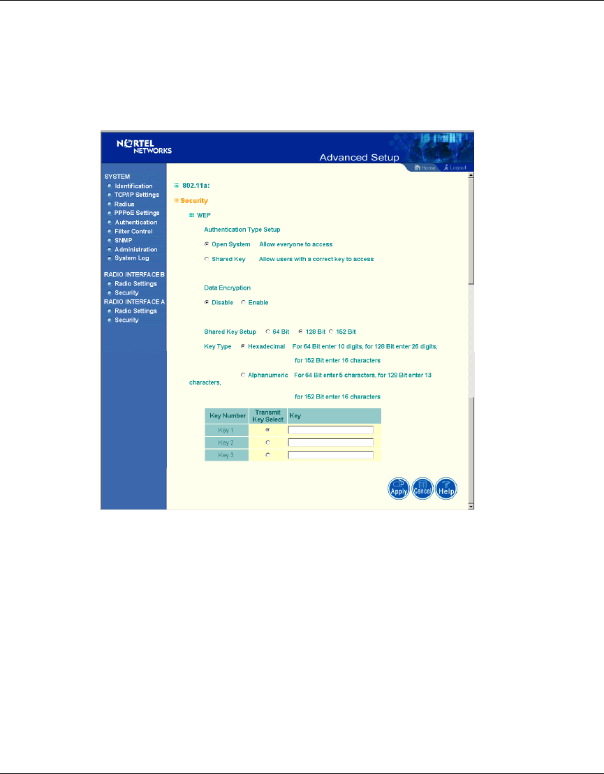
Security
WEP (Wired Equivalent Privacy)
Figure 23 Security screen
Authentication Type Setup
You may choose either “Open System” or “Shared Key.”
(Default: Open System)
If Shared Key is enabled, WEP should be enabled and at least one shared key
should be defined.
AccessPointUG.book Page 46 Thursday, February 27, 2003 12:22 PM

Chapter 2 System Configuration 47
Using the Nortel Networks Wireless LAN Access Point 2220
[Final Draft—Nortel Confidential]
Data Encryption
You may choose “Enable” to enhance your network security with WEP data
encryption
(Default: Disable)
If Shared Key is enabled, WEP should be enabled and at least one shared key
should be defined.
Standard Key Setup (WEP Default: 128)
Default Shared Key – Choose the Shared Key that has the encryption string you
prefer (Key 1~3).
The access point supports “Shared Key” encryption with key lengths from the
standard 64-bit, industry standard 128-bit, to the extended 152-bit. The bit key can
be in alphanumeric characters, or hexadecimal numerals (0~9, A~F, e.g., D7 0A
9C 7F E5.)
64-Bit Manual Entry
Key 1~3 - Each Key ID contains 10 HEX digits, or 5 alphanumeric characters.
128-Bit Manual Entry
Key ID contains 26 HEX digits, or 13 alphanumeric characters.
152-Bit Manual Entry
Key ID contains 32 HEX digits, or 16 alphanumeric characters.
1Select a unique key (1~3)
2Enter the encryption key and select the key size.
3Be sure to click the “Apply” button on the bottom of the page to make the
settings take effect.
Note: All wireless devices must have the same Key ID values to
communicate.
AccessPointUG.book Page 47 Thursday, February 27, 2003 12:22 PM
48 Chapter 2 System Configuration
214853-A
[Final Draft—Nortel Confidential]
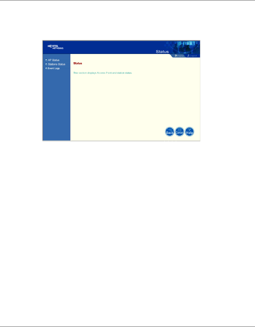
Status
Figure 24 Status screen
Clicking on the “Status” radio button on the home page displays additional
information about the access point status and station status as shown in the
following section.
AccessPointUG.book Page 48 Thursday, February 27, 2003 12:22 PM
Chapter 2 System Configuration 49
Using the Nortel Networks Wireless LAN Access Point 2220
[Final Draft—Nortel Confidential]
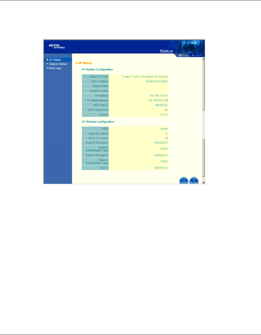
Access Point Status
Figure 25 AP Status screen
On the Status page, click “AP Status” to view the access point system
configuration and access point wireless configuration.
AccessPointUG.book Page 49 Thursday, February 27, 2003 12:22 PM
50 Chapter 2 System Configuration
214853-A
[Final Draft—Nortel Confidential]
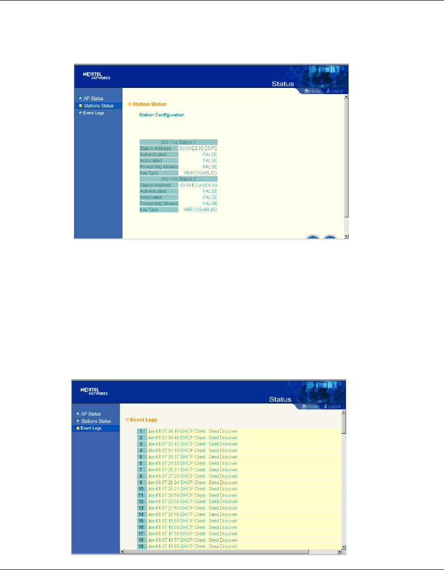
Station Status
Figure 26 Station Status screen
Click “Station Status” to view connected station configuration. The “Station
Statistics” page displays basic connection information for all associated stations.
The page is automatically refreshed every five seconds.
Event Logs
Figure 27 Event Logs screen
AccessPointUG.book Page 50 Thursday, February 27, 2003 12:22 PM

Chapter 2 System Configuration 51
Using the Nortel Networks Wireless LAN Access Point 2220
[Final Draft—Nortel Confidential]
Click “Event Logs” to display the activity logs of the access point.
Finding the MAC address of a Network Card
Windows 98/ME
Click “Start/Run”. Type “winipcfg” and press ENTER.
The MAC address is in the “Adapter Address” section.
Windows 2000/XP
At the command prompt, type “ipconfig /all” and press ENTER.
The MAC address is listed as the “Physical Address.”
AccessPointUG.book Page 51 Thursday, February 27, 2003 12:22 PM

52 Chapter 2 System Configuration
214853-A
[Final Draft—Nortel Confidential]
AccessPointUG.book Page 52 Thursday, February 27, 2003 12:22 PM
Chapter 3 Network Configuration and Planning 53
Using the Nortel Networks Wireless LAN Access Point 2220
[Final Draft—Nortel Confidential]
Chapter 3
Network Configuration and Planning
The wireless solution supports a stand-alone wireless network configuration as
well as an integrated configuration with 10/100 Mbps Ethernet LANs.
The wireless network cards, adapters, access points and wireless access point can
be configured as:
• Ad hoc for departmental or SOHO LANs
• Infrastructure for wireless LANs
• Infrastructure wireless LAN for roaming wireless PCs
Network Topologies
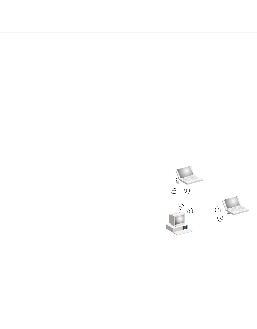
Ad Hoc Wireless LAN
(no AP or Bridge)
An ad hoc wireless LAN consists of a group
of computers, each equipped with a wireless
adapter, connected via radio signals as an
independent wireless LAN. Computers in a
specific ad hoc wireless LAN must therefore
be configured to the same radio channel. An
ad hoc wireless LAN can be used for a
branch office or SOHO operation.
Ad Hoc Wireless LAN
Notebook with
Wireless USB Adapter
Notebook with
Wireless PC Card
PC with Wireless
PCI Adapter
AccessPointUG.book Page 53 Thursday, February 27, 2003 12:22 PM
54 Chapter 3 Network Configuration and Planning
214853-A
[Final Draft—Nortel Confidential]
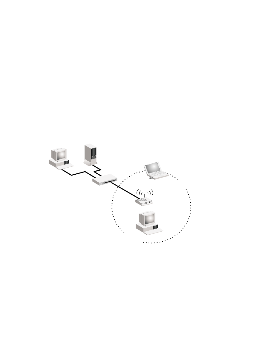
Infrastructure Wireless LAN
The access point can also provide access to a wired LAN for wireless
workstations. An integrated wired/wireless LAN is called an Infrastructure
configuration. A Basic Service Set (BSS) consists of a group of wireless PC users,
and an access point that is directly connected to the wired LAN. Each wireless PC
in this BSS can talk to any computer in its wireless group via a radio link, or
access other computers or network resources in the wired LAN infrastructure via
the access point.
The infrastructure configuration not only extends the accessibility of wireless PCs
to the wired LAN, but also increases the effective wireless transmission range for
wireless PCs by passing their signal through one or more access points.
A wireless infrastructure can be used for access to a central database, or for
connection between mobile workers, as shown in the following figure.
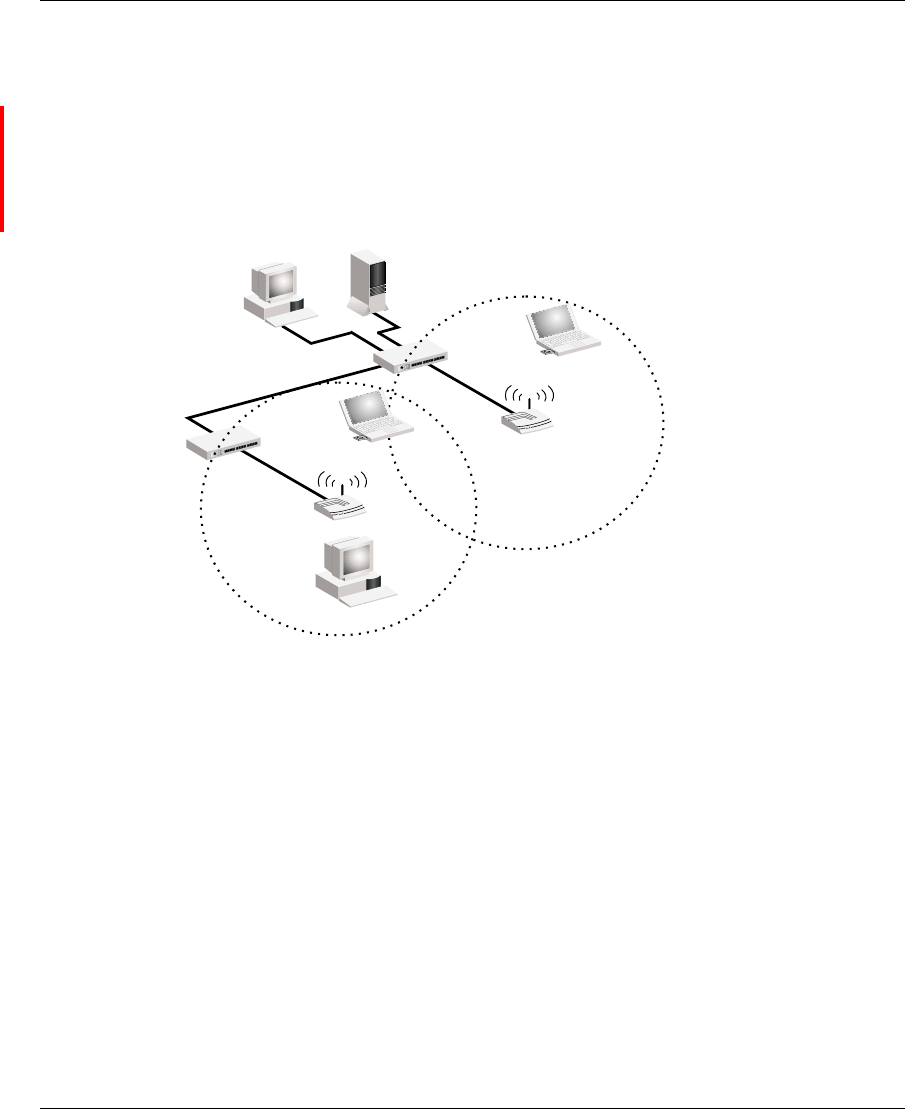
Infrastructure Wireless LAN for Roaming Wireless PCs
The Basic Service Set (BSS) is the communications domain for each wireless
access point. For wireless PCs that do not need to support roaming, set the domain
identifier (SSID) for the wireless card to the SSID of the access point to which
you want to connect. Check with your administrator for the SSID of the access
point or bridge to which he wants you to connect.
File
Server
Switch
Desktop PC
Access Point
Wired LAN Extension
to Wireless Adapters
PC with Wireless
PCI Adapter
Notebook with Wireless
PC Card Adapter
AccessPointUG.book Page 54 Thursday, February 27, 2003 12:22 PM
Chapter 3 Network Configuration and Planning 55
Using the Nortel Networks Wireless LAN Access Point 2220
[Final Draft—Nortel Confidential]
A wireless infrastructure can also support roaming for mobile workers. More than
one access point can be configured to create an Extended Service Set (ESS). By
placing the access points so that a continuous coverage area is created, wireless
users within this ESS can roam freely. All Nortel Networks Wireless LAN--Series
2200 wireless network cards and adapters and Access Point 2220 wireless access
points within a specific ESS must be configured with the same SSID
.
File
Server
Switch
Desktop PC
Access Point
<BSS2>
Notebook with Wireless
PC Card Adapter
Seamless Roaming
<ESS>
Switch
Access Point
<BSS1>
PC with Wireless
PCI Adapter
Notebook with Wireless
PC Card Adapter
AccessPointUG.book Page 55 Thursday, February 27, 2003 12:22 PM

56 Chapter 3 Network Configuration and Planning
214853-A
[Final Draft—Nortel Confidential]
AccessPointUG.book Page 56 Thursday, February 27, 2003 12:22 PM

Chapter 4 Troubleshooting 57
Using the Nortel Networks Wireless LAN Access Point 2220
[Final Draft—Nortel Confidential]
Chapter 4
Troubleshooting
Check the following items before you contact Nortel Technical Support.
1If mobile users do not have roaming access to the Access Point 2220, check
the following:
Make sure that all the access points and wireless devices in the ESS in which
the WLAN mobile users can roam are configured to the same WEP setting,
SSID, and authentication algorithm.
2If the access point cannot be configured using the Web browser:
• Turn off power to the access point.
• Pushintheresetbuttonlocatedonthebackoftheaccesspointtorestore
the factory default settings.
• Reconnect the power to the access point.
AccessPointUG.book Page 57 Thursday, February 27, 2003 12:22 PM

58 Chapter 4 Troubleshooting
214853-A
[Final Draft—Nortel Confidential]
AccessPointUG.book Page 58 Thursday, February 27, 2003 12:22 PM

59
Using the Nortel Networks Wireless LAN Access Point 2220
[Final Draft—Nortel Confidential]
Appendix A
Specifications
Reviewers: This material is being double-checked.
This appendix provides technical specifications for the Access Point 2220.
Maximum Channels
802.11a
US & Canada: 12 (normal mode), 5 (turbo mode)
Japan: 5 (normal mode), 1 (turbo mode)
802.11b
FCC/IC: 1-11, ETSI: 1-13, France: 10-13, Spain: 10-11, MKK: 1-14
Maximum Clients
64
(Default: 64) (Range 0 - 2007)
Operating Range
Up to 500 m (1640 ft)
Data Rate
Normal Mode: 6, 9, 12, 18, 24, 36, 48, 54 Mbps per channel
Turbo Mode: 12, 18, 24, 36, 48, 72, 96, 108 Mbps per channel
AccessPointUG.book Page 59 Thursday, February 27, 2003 12:22 PM

60 Appendix A Specifications
214853-A
[Final Draft—Nortel Confidential]
Operating Frequency
5.15 ~ 5.25 GHz (lower band) US/Canada, Japan
5.25 ~ 5.35 GHz (middle band) US/Canada
5.725 ~ 5.825 GHz (upper band) US/Canada
Power supply
Input: 100-240 AC, 50-60 Hz;
Output: 5 VDC, 3 A
Output Power
16 dBm minimum
Physical Size
20.5 x 13.6 x 4 cm, (8.07 x 5.35 x 1.58 in)
Weight
700 grams (1.5 lbs.)
LED Indicators
Ready (Power), LAN (Ethernet Link/Activity), WLANa and WLANb (Wireless Link/Activity)
Management
HTML Web-browser interface,
AccessPointUG.book Page 60 Thursday, February 27, 2003 12:22 PM

Appendix A Specifications 61
Using the Nortel Networks Wireless LAN Access Point 2220
[Final Draft—Nortel Confidential]
Temperature
Operating: 0 to 50 ºC (32 to 122 ºF)
Storage: 0 to 70 ºC(32to158ºF)
Humidity
5% to 95% (non-condensing)
Compliances
IEC 61000-4-2/3/4/6/11
Emissions
FCC Class B
RCR STD-33A
Safety
UL/CUL (UL60950 & CSA 22.2 NO. 60950-00)
EN60950, IEC60950 (CB)
Standards
IEEE 802.3 10BASE-T, IEEE 802.3u 100BASE-TX, IEEE 802.11a/b
Warranty
Limited Lifetime
AccessPointUG.book Page 61 Thursday, February 27, 2003 12:22 PM

62 Appendix A Specifications
214853-A
[Final Draft—Nortel Confidential]
AccessPointUG.book Page 62 Thursday, February 27, 2003 12:22 PM

63
Using the Nortel Networks Wireless LAN Access Point 2220
[Final Draft—Nortel Confidential]
Appendix B
Template for placing the Access Point 2220
The template on the next page can be used to assist in positioning the Access Point
2220. Mark where the wall-mount screws should go.
AccessPointUG.book Page 63 Thursday, February 27, 2003 12:22 PM

AccessPointUG.book Page 64 Thursday, February 27, 2003 12:22 PM